Embed Size (px)
Citation preview
Development of heterogenized catalyst systems forthe synthesis of acrylic acid derivatives from
carbon dioxide and ethylene
Von der Fakultät Energie-, Verfahrens- und Biotechnik der Universität Stuttgart
zur Erlangung der Würde eines
Doktors der Ingenieurwissenschaften (Dr.-Ing.) genehmigte Abhandlung
Vorgelegt von
Dipl.-Ing. Eko Prasetyo
aus Malang, Indonesia
Hauptberichter: Prof. Dr.-Ing. Elias KlemmMitberichter : Prof. Dr.-Ing. Ulrich Nieken
Tag der mündlichen Prüfung: 20. April 2015
Institut für Technische Chemie der Universität Stuttgart
2015

ii
Abstract
Use of CO2 as chemical feedstock represents one of the most sus-tainable ways for carbon recycling, generating high value products.Current industrial practices include the manufacture of urea, organic(poly)carbonates, and salicylic acid. CO2 can also be used to produceCO-rich syngas, which can be further processed to olefins, aldehydes,alcohols, or synthetic fuel via the Fischer-Tropsch process.Direct carboxylation with CO2 yielding carbonates, carbamates, car-boxylates, or lactones is of great importance from the industrial point ofview. The route has a high atom efficiency and avoids a complex processwith significant amounts of waste, which is common in multi-step con-ventional processes [1]. The synthesis of sodium acrylate from ethyleneand CO2 represents one of the most attractive carboxylations. Contraryto the current acrylate production process via propene oxidation, theprocess utilizing ethylene and CO2 discussed in this work utilizes thecheap and abundantly available CO2 as C1 building block.Current state of the art of sodium acrylate catalytic reaction from ethy-lene and CO2 utilizes a molecular nickel complex to form a nickel-alactone intermediate and a non-nucleophilic base to cleave nickel-alactone, yielding sodium acrylate product. This reaction requires acomplex process, with separate nickelalactone formation and cleavagewith subsequent sophisticated product separation and base recyclingprocesses. In addition, the alkoxide base may form inactive semi-carbonate with CO2 as well as form conjugate acid which deactivatesthe nickel complex catalyst. In this work, three different metal catalyst- base combinations are proposed to overcome these limitations.A combination of molecular nickel complex with CO2-stable tertiaryamine - NaH base system allows the one-pot process reaction with allreactants present during catalytic reaction. The tertiary amine is not
iii
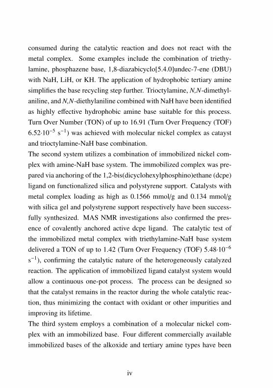
consumed during the catalytic reaction and does not react with themetal complex. Some examples include the combination of triethy-lamine, phosphazene base, 1,8-diazabicyclo[5.4.0]undec-7-ene (DBU)with NaH, LiH, or KH. The application of hydrophobic tertiary aminesimplifies the base recycling step further. Trioctylamine, N,N-dimethyl-aniline, and N,N-diethylaniline combined with NaH have been identifiedas highly effective hydrophobic amine base suitable for this process.Turn Over Number (TON) of up to 16.91 (Turn Over Frequency (TOF)6.52⋅10−5 s−1) was achieved with molecular nickel complex as cataystand trioctylamine-NaH base combination.The second system utilizes a combination of immobilized nickel com-plex with amine-NaH base system. The immobilized complex was pre-pared via anchoring of the 1,2-bis(dicyclohexylphosphino)ethane (dcpe)ligand on functionalized silica and polystyrene support. Catalysts withmetal complex loading as high as 0.1566 mmol/g and 0.134 mmol/gwith silica gel and polystyrene support respectively have been success-fully synthesized. MAS NMR investigations also confirmed the pres-ence of covalently anchored active dcpe ligand. The catalytic test ofthe immobilized metal complex with triethylamine-NaH base systemdelivered a TON of up to 1.42 (Turn Over Frequency (TOF) 5.48⋅10−6
s−1), confirming the catalytic nature of the heterogeneously catalyzedreaction. The application of immobilized ligand catalyst system wouldallow a continuous one-pot process. The process can be designed sothat the catalyst remains in the reactor during the whole catalytic reac-tion, thus minimizing the contact with oxidant or other impurities andimproving its lifetime.The third system employs a combination of a molecular nickel com-plex with an immobilized base. Four different commercially availableimmobilized bases of the alkoxide and tertiary amine types have been
iv

identified as effective in the one-pot sodium acrylate reaction. Further-more, two CO2-atmosphere tolerant immobilized bases were preparedvia direct anchoring on polystyrene support and via copolymerizationreaction. A high TON of up to 30.94 (TOF 4.30⋅10−4 s−1) could beachieved with the combination of (dcpe)-nickelalactone catalyst and im-mobilized sodium 2-fluorophenolate. In addition, successful recyclingexperiments of the immobilized base confirmed the versatility and suit-ability of the immobilized base for the catalytic reaction. A continuousprocess with two steps-filtration to recycle the immobilized base andisolate the sodium acrylate product is proposed as the most promisingconcept for an industrial application.
v
Zusammenfassung
Die Nutzung von CO2 als chemischer Rohstoff ist eine der nachhaltig-sten Wege zur Kohlenstoffwiederverwertung. Dadurch werden Pro-dukte mit hoher Wertschöpfung zugänglich. Die aktuellen industriellenProzesse sind z. B. die Herstellung von Harnstoff, organische (Poly)Carbonateund Salicylsäure. Des Weiteren kann CO2 auch in CO-reiches Synthe-segas verwandelt werden, das zu Olefinen, Aldehyden, Alkoholen odersynthetischen Kraftstoff (Fischer-Tropsch) verarbeitet werden kann.Außerdem, direkte Carboxylierung mit CO2 zu Carbonate, Carbamate,Carbonsäureester oder Lactone ist für die industrielle Anwendung sehrinteressant. Die Reaktion hat eine hohe Atomeffizienz, der Prozess wirdeinfacher, effizienter und es entstehen weniger Abfälle [1]. Die Syn-these von Natriumacrylat aus Ethylen und CO2 ist eine der attraktivstenCarboxylierungsreaktionen. Derzeit wird Natriumacrylat in einer zwei-stufigen Reaktion aus Propen hergestellt. Der potenzielle Neuprozessunter Verwendung von Ethylen und CO2 nutzt das billige, in großenMengen verfügbaren C1-Kohlenstoffquelle, CO2.Aktueller Stand der Technik von der katalytischen Reaktion von Na-triumacrylat aus Ethylen und CO2 verwendet ein Nickelkomplex, dasein Nickelalacton-Intermediat bildet, und eine nicht-nukleophile Base,die das Nickelalacton spaltet. Die Reaktion ist sehr komplex, mit einerseparaten Bildung und Spaltung von Nickelalacton mit anschließen-der anspruchsvoller Produkttrennung und Wiederverwertung von Base.Dabei kann die Alkoxide (Base) ein inaktives Semicarbonat und kon-jugierte Säure bildet, die der Nickelkomplex-Katalysator deaktivieren.In dieser Arbeit werden drei verschiedene Kombinationen von demKatalysator und der Base untersucht, um die Limitierungen zu über-windenEine Kombination von homogenem Nickelkomplex mit CO2-stabilem
vi

tertiärem Amin – NaH Basesystem ermöglicht den Eintopf-Prozessmit allen Reaktanten anwesend während der katalytischen Reaktion.Während der katalytischen Reaktion wird das tertiäre Amin weder ver-braucht noch mit dem Metallkomplex reagiert. Einige Beispiele fürBasesystemen sind jede Kombination aus Triethylamin, Phosphazen,1,8-diazabicyclo[5.4.0]undec-7-ene (DBU) mit NaH, LiH oder KH.Außerdem, der Einsatz von hydrophobem tertiärem Amin vereinfachtdie Wiederverwertung von Base. Die Kombinationen aus Triocty-lamin, N,N-dimethylanilin oder N,N-diethylanilin mit NaH waren hoch-effektives Basesystem für den Prozess. Turn Over Number (TON) vonbis zu 16,91 (Turn Over Frequency (TOF) 6,52⋅10−5 s−1) wurde erreichtmit molekularem Nickelkomplex als Katalysator und eine Kombinationvon Trioctylamin mit NaH als Base.Das zweite System ist die Kombination von immobilisiertem Nick-elkomplex mit Amin-NaH. Der immobilisierte Komplex wurde durchVerankerung des 1,2-bis(dicyclohexylphosphino)ethane (dcpe) auf funk-tionalisierte Silica und Polystyrrol Support vorbereitet. Katalysator mitMetallkomplex Beladung von bis zu 0,1566 mmol/g mit Silica Sup-port und 0,134 mmol/g mit Polystyrol Support wurden erfolgreich syn-thetisiert. MAS-NMR-Untersuchungen bestätigen die Anwesenheit vonkovalent-gebundenen dcpe Liganden. Katalytische Untersuchung vondiesem System lieferte eine TON von bis zu 1,42 (Turn Over Frequency(TOF) 5,48⋅10−6 s−1). Der Einsatz von immobilisiertem Komplex würdeeinen kontinuierlichen Eintopf-Prozess ermöglichen. Der Prozess kannso gestaltet werden, dass während der gesamten katalytischen Reaktionder Katalysator im Reaktor bleibt. Dadurch kann der Kontakt mit Ox-idationsmittel oder anderen Verunreinigungen vermeidet werden, waszur Verbesserung der Lebensdauer des Katalysators führen kann.
vii

Im dritten System wurden Kombinationen aus Nickelkomplex und im-mobilisierten Basen verwendet. Vier verschiedene kommerzielle immo-bilisierte Basen (Alkoxid und tertiäres Amin) waren effektiv in Eintopf-Reaktion von Natriumacrylat. Ferner wurden zwei CO2 stabile immo-bilisierte Basen sowohl durch direkte Verankerung auf Polystyrol Sup-port als auch durch Copolymerisationsreaktion vorbereitet. Eine hoheTON von bis zu 30,94 (TOF 4,30⋅10−4 s−1) konnte mit der Kombi-nation von molekularem (dcpe)-Nickelalacton-Katalysator und immo-bilisiertem Natrium-2-fluorophenolat erreicht werden. Zusätzlich, er-folgreiche Recyclingsversuche von immobilisierten Basen bestätigt dieVielseitigkeit und die Eignung dieser immobilisierten Basen in einekatalytische Reaktion. Ein kontinuierliches Verfahren mit zweistufigeFiltration zum Trennen der immobilisierten Base und zur Gewinnungvon Natriumacrylat wird als das vielversprechendste Konzept für eineindustrielle Anwendung vorgeschlagen.
viii

Acknowledgments
This work would not have been possible without the encouragement andthe assistance of others.I would like to thank my supervisor at hte GmbH, Dr. Stephan A.Schunk, for giving me a chance to work on a very interesting themeand teaching me to push myself, aim high, and never settle for less thanmy very best.I thank my supervisor at University of Stuttgart, Prof. Dr.-Ing. EliasKlemm, for his scientific support and fruitful discussions. I wouldalso like to express my gratitude to Prof. Dr.-Ing. Ulrich Nieken forexamining my dissertation.I would like to thank Dr. Michael Lejkowski for sharing his strong sci-entific experiences and providing ideas and insights into organometallicand organic chemistry. He is always enthusiastic to answer my endlessquestions.I am also grateful to Dr. Alvaro Gordillo for his scientific advice,knowledge, and suggestions. I have learned a lot about organometallicchemistry especially hydrosilylation from him.I owe a particular debt of gratitude to apl. Prof. Dr. Michael Hunger forhis assistance and friendly discussion with MAS-NMR measurement.To the members of liquid phase lab, past and present, especially JörgRother, Angelo Brau, Mathias Boesing, Adrien Schmidt, and DanielWendt, I would like to express my gratitude for the strong support andhelp on the screening experiments.I am very grateful for the great team work at hte GmbH and wouldlike to especially acknowledge synthesis laboratory members, AndreasStrasser, Simon Holz, Michael Bartz, and Robert Müller for their assis-tance and support during my first half PhD working on heterogeneouscatalysis and the members of analytical laboratory, particularly Tamara
ix

Gabriel, Stefanie Wagner and Oliver Laus for their support with GC-MS, X-ray diffraction, BET, DSC, STA-TG, and FTIR measurements.I thank:
• CaRLa’s team: Dr. Michael Limbach, Dr. Nuria Huguet, Dr.Ivana Jevtovikj, and Dr. Ronald Lindner for their assistance andhelp with my chemistry questions.
• Sandra Weber from University of Stuttgart for her help with NMRmeasurement.
I would like to thank my friends, especially Thomas Roussiere, LuisTojil Alvarado Rupflin, and Timo Emmert for the interesting scientificdiscussion and for the great time during my PhD work.The financial support from the German Federal Ministry of Educa-tion and Research (Chemische Prozesse und stoffliche Nutzung vonCO2: Technologien für Nachhaltigkeit und Klimaschutz) is gratefullyacknowledged.Finally, I would like to thank my dad, my grandma, and my sistersfor their support. They always encourage me and help me pursue mydreams. I thank them from the bottom of my heart. This dissertation isdedicated to them.
x

Eigenständigkeitserklärung
Hiermit erkläre ich, dass ich die Dissertation, abgesehen von den aus-drücklich bezeichneten Hilfsmittel, selbständig verfasst habe.
Stuttgart, den 30.10.2014
Eko Prasetyo
xi

xii

Contents
Abstract iii
Zusammenfassung vi
Acknowledgments ix
Contents xiii
List of Figures xvii
List of Tables xxv
1 Introduction 11.1 State of the Art Production of Acrylates . . . . . . . . . 3
1.2 Alternative Routes to Sodium Acrylate . . . . . . . . . . 6
1.3 CO2 as Chemical Feedstock . . . . . . . . . . . . . . . . 8
1.3.1 Bonding of CO2 to Metal Centers . . . . . . . . 18
1.3.2 Reactivity of Activated CO2 . . . . . . . . . . . 18
1.4 Catalysis . . . . . . . . . . . . . . . . . . . . . . . . . . . 21
1.5 State of the Art . . . . . . . . . . . . . . . . . . . . . . . 42
1.6 Process Design . . . . . . . . . . . . . . . . . . . . . . . 48
xiii

2 Homogeneous Process 552.1 Liquid Base - NaH System . . . . . . . . . . . . . . . . . 55
2.1.1 Process Design Options . . . . . . . . . . . . . . 58
2.1.2 Types of Bases . . . . . . . . . . . . . . . . . . . 62
2.1.3 Effect of the Reaction Temperature . . . . . . . 70
2.1.4 Effect of the Cation Sources . . . . . . . . . . . 72
2.1.5 Improvement in Process Design . . . . . . . . . 78
2.2 Nickelalactone . . . . . . . . . . . . . . . . . . . . . . . 82
2.3 Conclusion . . . . . . . . . . . . . . . . . . . . . . . . . 89
3 Heterogeneous Process 913.1 Theory . . . . . . . . . . . . . . . . . . . . . . . . . . . . 91
3.2 Process Design Options . . . . . . . . . . . . . . . . . . 95
3.3 Catalyst Design via Anchoring . . . . . . . . . . . . . . 98
3.3.1 Route 1: In situ sequential assembly of activeligand . . . . . . . . . . . . . . . . . . . . . . . . 110
3.3.2 Route 2: Direct anchoring of active ligand . . . 118
3.4 Catalytic Performance Results . . . . . . . . . . . . . . . 139
3.5 Conclusion . . . . . . . . . . . . . . . . . . . . . . . . . 146
4 Heterogeneous Process 1494.1 Theory: Cleavage of Ni-Lactone . . . . . . . . . . . . . 149
4.2 Process Design Options . . . . . . . . . . . . . . . . . . 151
4.3 Application of the Immobilized Bases . . . . . . . . . . 153
4.3.1 Design of the Immobilized Base . . . . . . . . . 158
4.3.2 Recycling of the Immobilized Base System . . 165
4.4 Conclusion . . . . . . . . . . . . . . . . . . . . . . . . . 167
5 Conclusions 171
xiv

A Experimental Section 179A.1 High Throughput Experimentation . . . . . . . . . . . . 179A.2 Catalytic reaction . . . . . . . . . . . . . . . . . . . . . . 183A.3 Ligand immobilization . . . . . . . . . . . . . . . . . . . 188
A.3.1 Route 1: In situ sequential assembly of activeligand . . . . . . . . . . . . . . . . . . . . . . . . 188
A.3.2 Route 2: Direct anchoring of active ligand . . . 191A.4 Base . . . . . . . . . . . . . . . . . . . . . . . . . . . . . 195
A.4.1 Synthesis of immobilized base via direct an-choring . . . . . . . . . . . . . . . . . . . . . . . 195
A.4.2 Synthesis of immobilized base via copolymer-ization . . . . . . . . . . . . . . . . . . . . . . . 197
B List of Chemicals 201
xv

xvi

List of Figures
1-1 Acrylic acid synthesis via cyanohydrin route. . . . . . . 3
1-2 Acrylic acid synthesis via acrylonitrile hydrolysis route. 4
1-3 Reppe’s carbonylation of acetylene. . . . . . . . . . . . 4
1-4 Acrylic acid synthesis via two steps oxidation of propene. 5
1-5 Four steps PSA process. . . . . . . . . . . . . . . . . . . 10
1-6 Chemical utilization of CO2 [35]. . . . . . . . . . . . . . 11
1-7 Industrial chemical utilization of CO2. . . . . . . . . . . 12
1-8 Coordination modes of CO2 to metal centers [36, 86]. . 18
1-9 Activation modes of CO2 leading to chemical transfor-mation [35]. . . . . . . . . . . . . . . . . . . . . . . . . . 19
1-10 Catalyst opens up new reaction pathways with loweractivation energies. . . . . . . . . . . . . . . . . . . . . . 21
1-11 Fundamental reaction in organometallic catalysis: As-sociation and Dissociation [190]. . . . . . . . . . . . . . 29
1-12 Fundamental reaction in organometallic catalysis: Ox-idative Addition and Reductive Elimination [190]. . . . 30
1-13 Fundamental reaction in organometallic catalysis: In-sertion and De-insertion [190]. . . . . . . . . . . . . . . 30
1-14 Fundamental reaction in organometallic catalysis: Ox-idative Coupling and Reductive Cleavage [190]. . . . . 31
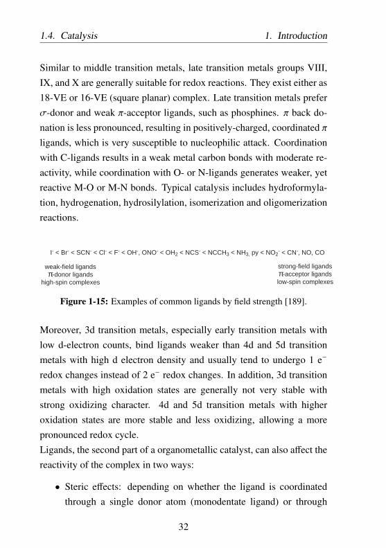
1-15 Examples of common ligands by field strength [189]. . 32
xvii

1-16 Some phosphine ligands with increasing nucleophilicityfrom left to right. . . . . . . . . . . . . . . . . . . . . . . 33
1-17 Seven steps of heterogeneously catalyzed reaction. . . . 38
1-18 Effective reaction rate as a function of reaction temper-ature. . . . . . . . . . . . . . . . . . . . . . . . . . . . . . 39
1-19 Langmuir-Hinshelwood mechanism (left) and Eley-Ridealmechanism (right). . . . . . . . . . . . . . . . . . . . . . 40
1-20 Hypothetical catalytic cycle leading to acrylic acid fromCO2 and ethylene according to Walther et al [200]. . . . 43
1-21 Hypothetical catalytic cycle leading to acrylates fromCO2 and ethylene with 1,2-bis(di-tert-butylphosphino)-ethane (dtbpe) ligand [203]. . . . . . . . . . . . . . . . . 44
1-22 List of ligands investigated by Limbach et al. for nickel-alactone formation [203]. dppm: 1,1-bis(diphenylphosphino)methane,dppe:1,2-bis(diphenylphosphino)ethane, dppp:1,3-bis(diphenylphosphino)propane,dtbpm:1,1-bis(di-tert-butylphosphino)methane, dtbpe:1,2-bis(di-tert-butylphosphino)ethane, dtbpp:1,3-bis(di-tert-butylphosphino)propane . . . . . . . . . . . . . . . . . . 45
1-23 Process 1.1: Use of a molecular catalyst nickel complexand CO2-sensitive alkoxide base in catalytic acrylatereaction. . . . . . . . . . . . . . . . . . . . . . . . . . . . 50
1-23 (cont.) . . . . . . . . . . . . . . . . . . . . . . . . . . . . 51
2-1 Hypothetical catalytic cycle leading to acrylates fromCO2 and ethylene with 1,2-bis(dicyclohexylphosphino)-ethane (dcpe) ligand and amine-NaH base system. . . . 56
xviii
2-2 Active bases investigated in this work. pKA values inacetonitrile in parentheses. Exception: N,N-dimethylanilineand N,N-diethylamine pKA values in water [207–209].P1:tert-butyl-tris(dimethylamino)phosphorane, P2:1-tert-butyl-2,2,4,4,4-pentakis(dimethylamino)-2λ5,4λ5
−catenadi(phosphazene),P4 ∶1 − tert − butyl − 4,4,4 − tris(dimethylamino) − 2,2 −bis[tris(dimethylamino) − phosphoranylidenamino] −2λ5,4λ5
− catenadi(phosphazene),BEMP ∶ 2 − tert −butylimino−2−diethylamino−1,3−dimethylperhydro−1,3,2−diazaphosphorine,DBU ∶ 1,8−diazabicyclo[5.4.0]undec−7 − ene,T EA ∶ triethylamine. . . . . . . . . . . . . . . . 57
2-3 Process 1.2: Use of a molecular catalyst nickel complexand CO2-stable amine-NaH base in catalytic acrylatereaction. . . . . . . . . . . . . . . . . . . . . . . . . . . . 60
2-3 (cont.) . . . . . . . . . . . . . . . . . . . . . . . . . . . . 61
2-4 Effectivity of different liquid bases during catalytic re-action. Parameters: 0.2 mmol Ni(COD)2, 0.22 mmoldcpe, 2.5 mmol base (except for P4: 1 mmol), 10 mmolNaH, 5 bar ethylene, 10 bar CO2, 45 mL THF, T = 80○C, t = 18 or 72 hours. See also Figure 2-6 for reactionswith trioctylamine at optimized reaction parameters. . . 63
2-5 Side reaction of triazabicyclo[4.4.0]dec-5-ene (secondaryamine) with CO2 [211]. . . . . . . . . . . . . . . . . . . 64
2-6 Effectivity of different liquid bases during catalytic re-action. Parameters: 0.2 mmol Ni(COD)2, 0.22 mmoldcpe, 10 mmol base, 10 mmol NaH, 10 bar ethylene, 20bar CO2, 45 mL THF, T = 100 ○C, t = 18 or 72 hours. . 64
xix

2-7 Effectivity of different liquid bases during catalytic re-action. Parameters: 0.2 mmol Ni(COD)2, 0.22 mmoldcpe, 2.5 mmol base (except for P4: 1 mmol), 10 mmolNaH, 5 bar ethylene, 10 bar CO2, 45 mL THF, T = 80○C, t = 18 or 72 hours. . . . . . . . . . . . . . . . . . . . 65
2-8 Dependency of base amount to catalytic activity. Param-eters: 0.2 mmol Ni(COD)2, 0.22 mmol dcpe, P1 base,10 mmol NaH, 5 bar ethylene, 10 bar CO2, 45 mL THF,T = 80 ○C, t = 18 or 100 hours. . . . . . . . . . . . . . . 69
2-9 Decomposition of (dcpe)-nickelalactone yielding dcpemonooxide, dcpe dioxide, and Ni(0). . . . . . . . . . . . 70
2-10 Temperature dependency of acrylate catalytic reaction.Parameters: 0.2 mmol Ni(COD)2, 0.22 mmol dcpe, 2.5mmol P1, 50 mmol NaH, 5 bar ethylene, 10 bar CO2,45 mL THF, t = 18 hours (Table 2.1 Entry 3-9). . . . . . 71
2-11 Hypothetical hydrolysis of (dcpe)-nickelalactone withwater during extraction to give propionic acid. . . . . . 72
2-12 Hypothetical cleavage of (dcpe)-nickelalactone with amine-NaH base system to give sodium acrylate. . . . . . . . . 73
2-13 Effectivity of different liquid base - additive systemsduring catalytic reaction. Parameters: 0.2 mmol Ni(COD)2,0.22 mmol dcpe, 2.5 mmol base, 50 mmol additive, 5bar ethylene, 10 bar CO2, 45 mL THF, T = 80 ○C, t =
18 or 72 hours. . . . . . . . . . . . . . . . . . . . . . . . 74
2-14 Process 1.3: Use of a molecular catalyst nickel complexand water-insoluble base in catalytic acrylate reaction. . 80
2-14 (cont.) . . . . . . . . . . . . . . . . . . . . . . . . . . . . 81
2-15 Preparation of (dcpe)-nickelalactone species via ligandexchange. . . . . . . . . . . . . . . . . . . . . . . . . . . 83
xx
2-16 Nickelalactone as precursor for the catalytic cycle. Pa-rameters: 0.2 mmol Ni(COD)2 and 0.22 mmol dcpe or0.2 mmol (dcpe)-nickelalactone, 100 eq. NaH, 10 barethylene, 20 bar CO2, 45 mL THF, T = 100 ○C, t = 20or 72 hours. . . . . . . . . . . . . . . . . . . . . . . . . . 84
2-17 Nickelalactone as precursor for the catalytic cycle. Pa-rameters: 0.2 mmol Ni(COD)2 and 0.22 mmol dcpe or0.2 mmol (dcpe)-nickelalactone, 100 eq. NaH, 10 barethylene, 20 bar CO2, 45 mL THF, T = 100 ○C, t = 20or 72 hours. . . . . . . . . . . . . . . . . . . . . . . . . . 85
2-18 Dependency of base amount to catalytic activity. Param-eters: (dcpe)-nickelalactone precursor, triethylamine base,NaH cation source, 45 mL THF, 10 bar ethylene, 20 barCO2, T = 100 ○C, t = 20 hours. . . . . . . . . . . . . . . 87
3-1 Hypothetical catalytic cycle leading to acrylates fromCO2 and ethylene with immobilized 1,2-bis(dicyclohexyl-phosphino)-ethane (dcpe) ligand and amine-NaH basesystem. . . . . . . . . . . . . . . . . . . . . . . . . . . . . 94
3-2 Process 2: Use of immobilized molecular catalyst andwater-insoluble base in catalytic acrylate reaction. . . . 96
3-3 Long, flexible linker resulting in a strong interactionbetween metal complex and the solid matrix. . . . . . . 99
3-4 Simplified schema of two synthetic approaches for lig-and immobilization. Top: Sequential assembly of activeligand, bottom: Direct anchoring of active ligand. . . . 101
3-5 Functionalization of silica surface with silanes in anhy-drous conditions [248]. . . . . . . . . . . . . . . . . . . . 105
3-6 Functionalization of silica surface with silanes underaqueous conditions [248]. . . . . . . . . . . . . . . . . . 108
xxi

3-7 Activated position of a phosphorous compound uponcomplexation with BH3 [250]. . . . . . . . . . . . . . . 109
3-8 Simplified anchoring mechanism via SN2 reaction be-tween a linker-functionalized support and a ligand. . . . 110
3-9 Preparation of 4-oxa-6,7-dichloro-1-heptyltrimethoxysilanelinker. . . . . . . . . . . . . . . . . . . . . . . . . . . . . 111
3-10 Chalk-Harrod mechanism for hydrosilylation of olefinsby late transition metal complexes [266]. . . . . . . . . 113
3-11 Assembling the building blocks of 1,2-bis(dicyclohexyl-phosphino)-ethane (dcpe) on support. . . . . . . . . . . 117
3-12 Supports used for dcpe immobilization via direct an-choring route. Loading of Cl and Br moiety was de-termined by elemental analysis department of BASF. . . 119
3-13 Direct anchoring of 1,2-bis(dicyclohexylphosphino)-ethane(dcpe). . . . . . . . . . . . . . . . . . . . . . . . . . . . . 124
3-14 Common solvents for lithiation [271]. . . . . . . . . . . 126
3-15 31P MAS NMR for immobilized dcpe⋅2 BH3 on silicasupport S1 (A4, see also Table 3.6). . . . . . . . . . . . 131
3-16 31P MAS NMR for immobilized dcpe⋅2 BH3 on polystyrenesupport PS03 (A8.8, see also Table 3.6). . . . . . . . . . 131
3-17 31P MAS NMR for dcpe⋅2 BH3 immobilized on silicasupport S1 (A4, see also Table 3.6) after treatment with20 eq. dabco with THF as solvent at 100 ○C for 24 hours. 135
3-18 31P MAS NMR for dcpe immobilized on silica supportS1 (A4, see also Table 3.6) after treatment with excessmorpholin (10 mL for 1 g catalyst) at 110 ○C for 3 hours. 136
xxii

3-19 31P MAS NMR for dcpe immobilized on polystyrenesupport PS03 (A8.8, see also Table 3.6) after treatmentwith excess morpholin (10 mL for 1 g catalyst) at 110○C for 3 hours. . . . . . . . . . . . . . . . . . . . . . . . 137
3-20 31P MAS NMR for immobilized dcpe anchored on SBA-15 after ligand exchange with (tmeda)-nickelalactone.Deprotection conditions: excess morpholin at 110 ○Cfor 3 hours. . . . . . . . . . . . . . . . . . . . . . . . . . 139
3-21 31P MAS NMR for immobilized dcpe anchored on silicagel Cariact Q-20C after ligand exchange with (tmeda)-nickelalactone. Deprotection conditions: excess mor-pholin at 110 ○C for 3 hours. . . . . . . . . . . . . . . . 139
3-22 Overview of immobilized ligand investigated. . . . . . . 141
4-1 Hypothetical catalytic cycle leading to acrylates fromCO2 and ethylene with 1,2-bis(dicyclohexylphosphino)-ethane (dcpe) ligand and immobilized base system. . . . 150
4-2 Process 3: Use of a molecular catalyst nickel complexand immobilized base in catalytic acrylate reaction. . . 152
4-3 Overview of immobilized base investigated. . . . . . . . 154
4-4 Kolbe-Schmitt reaction: aromatic electrophilic substitu-tion of sodium phenoxide with CO2 [50–53]. . . . . . . 159
4-5 Activated position for aromatic electrophilic substitu-tion. Red dot: activation due to ONa moiety. Blue dot:activation due to F moiety. . . . . . . . . . . . . . . . . . 159
4-6 Support used for base immobilization via direct anchor-ing route. . . . . . . . . . . . . . . . . . . . . . . . . . . . 160
4-7 Anchoring of 2-fluorophenol onto polystyrene support. 161
4-8 Immobilization of 2-fluorophenol via copolymerization. 163
xxiii

4-9 Recyclability of immobilized sodium phenoxide in thecatalytic acrylate reaction. . . . . . . . . . . . . . . . . . 168
5-1 Process profitability of different metal catalyst - basecombinations for sodium acrylate reaction from ethy-lene and CO2. Values were calculated from the experi-ments with the highest yield in sodium acrylate. . . . . 176
A-1 Schematic drawing of a single autoclave unit. . . . . . . 181A-2 Schematic representation of a multi-fold autoclave sys-
tem (only two autoclaves are shown). . . . . . . . . . . . 182
B-1 PS01 - PS05 were purchased from Sigma Aldrich. S1and S2 supports were prepared from Cariact Q-20C.BrSBA-15 was prepared from SBA-15. For preparationmethod see also Appendix A.3.2. . . . . . . . . . . . . . 203
B-2 Commercial immobilized base. . . . . . . . . . . . . . . 204
xxiv

List of Tables
1.1 Emerging Alternative Route to Acrylic Acid [3, 15] . . 7
1.2 Industrial chemical processes with CO2 as feedstock. . 12
1.3 Direct carboxylation of organic compounds with CO2. . 20
1.4 Differences between molecular and solid catalysts [168,169]. . . . . . . . . . . . . . . . . . . . . . . . . . . . . . 23
1.5 Industrial processes with molecular transition metal cat-alysts [170]. . . . . . . . . . . . . . . . . . . . . . . . . . 24
1.6 Ligand types in molecular transition metal catalysts [189]. 28
1.7 Industrial processes with solid catalysts [170]. . . . . . 34
1.8 Nickelalactone formation with various ligands investi-gated by Limbach et al. [203]. Solvent: THF, 2 barethylene, 6 bar CO2, 50 ○C, 72 hours. . . . . . . . . . . 46
1.9 List of bases investigated by Limbach et al. for (dtbpe)-nickelalactone cleavage [203]. Solvent: Chlorobenzene,0.025 mmol (dtbpe)-nickelalactone, 0.1 mmol base, op-tionally 0.05 mol NaBArF , 30 bar ethylene. . . . . . . . 47
2.1 Effectivity of different liquid bases during catalytic re-action. Parameters: 0.2 mmol Ni(COD)2, 0.22 mmoldcpe, 45 mL THF, cation source: NaH. Entries illus-trated in Figure 2-4 and Figure 2-6 are marked in blue . 67
xxv

2.2 Effectivity of different cation sources during catalyticreaction. Parameters: 0.2 mmol Ni(COD)2, 0.22 mmoldcpe, 45 mL THF, base: P1, P2, or triethylamine (NEt3). 76
2.3 List of active bases and their solubility in water and THF. 78
2.4 Use of (dcpe)-nickelalactone as catalyst precursor. Pa-rameters: 10 bar ethylene, 20 bar CO2, 45 mL THF,temperature = 100 ○C, base: P1, triethylamine (NEt3),or trioctylammine (TOA). . . . . . . . . . . . . . . . . . 88
3.1 Leaving groups ordered approximately in decreasingability to leave [249] . . . . . . . . . . . . . . . . . . . . 106
3.2 Silica support used for functionalization via Route 1: Insitu sequential assembly of active ligand. . . . . . . . . 111
3.3 Hydrosilylation of 4-oxa-6,7-dichloro-1-heptene with 1.1eq. trimethoxysilane to give 4-oxa-6,7-dichloro-1-heptyl-trimethoxysilane. The conversion values are calculatedfrom the ratio of hydrosilylated product to educt withdouble bond 1H NMR spectra. ⋆byproduct: 4-oxa-6,7-dichloro-1-heptyltriisopropoxysilane. Note that all re-actions are carried out in a small vial with minimumamount of substances, thus inhomogenity is to be ex-pected, which is caused primarily due to improper stirring.114
3.4 Silica supports used for functionalization. . . . . . . . . 120
3.5 Grafting of silica support with 3-bromopropyltrimethoxysilane(BrSi). Synthetic details can be found in Appendix A.3.2. 122
xxvi

3.6 Direct anchoring of dcpe on the support material vianucleophilic substitution. Values of dcpe loading werederived from elemental analysis results. X = linker load-ing on the support material. Degree of anchoring = ratioof anchored dcpe to dcpe starting material. Conditions:⋆A: 2h at -40 ○C, 72h at 25 ○C. ⋆B: 24h at 0 ○C. ⋆C:72h at 0 ○C. ⋆D: 6h at -75 ○C, 16h at 0 ○C. ⋆E: 6h at -75○C, 8h at 0 ○C. ⋆F: 6h at -75 ○C, 90h at 0 ○C. ⋆G: 72hat 0 ○C. Remarks: ⋆1: support pre-dried in vacuum at50 ○C overnight. ⋆2: support pre-dried in vacuum at 25○C overnight, addition of 20 eq. LiH during anchoring.⋆3: support pre-dried in vacuum at 25 ○C overnight. ⋆4:support pre-dried in vacuum at 0 ○C overnight. . . . . . 128
3.7 Deprotection of non-immobilized dcpe⋅2 BH3. NMRSelectivity and conversion were determined from theintegral of each compound in 31P NMR spectra. . . . . 133
3.8 Catalytic activity of deprotected dcpe. Parameters: 0.2mmol Ni(COD)2, 0.22 mmol ligand, Base: 2.5 mmolP1, 10 mmol NaH, 5 bar ethylene, 10 bar CO2, 45 mLTHF, T = 80 ○C. Values in parenthesis represent hypo-thetical TON for 0.2 mmol molecular catalyst (100 %ligand is active). . . . . . . . . . . . . . . . . . . . . . . . 134
3.9 Reference data 31P NMR. . . . . . . . . . . . . . . . . . 136
xxvii

3.10 Activity of immobilized ligand in the catalytic acrylatereaction. Solvent: 45 mL THF. Temperature = 100 ○C,Cation source: NaH, Base: Triethylamine (NEt3) orN,N-dimethylaniline (DMA). Assumption: all immobi-lized ligands are successfully complexated with Nickeland are active. TON is refered to the amount of immo-bilized ligand measured via elemental analysis. . . . . . 142
4.1 Effectivity of immobilized base in the catalytic acrylatereaction. Parameters: 0.2 mmol Ni(COD)2, 0.22 mmoldcpe, 45 mL THF, NaH as cation (Na+) source. Excep-tion: Entry 9 with 0.1 mmol (dcpe)-nickelalactone. . . . 157
4.2 Anchoring of 2-fluorophenol on the polystyrene supportPS05. Base loading values were derived from elementalanalysis results. X = Br moiety on the catalyst support.Base:X ratio = 0.5 mmol/mmol. Degree of anchoring =
ratio of anchored base to base starting material. . . . . . 161
4.3 Recyclability of immobilized sodium phenoxide in thecatalytic acrylate reaction. Parameters: 0.2 mmol (dcpe)-nickelalactone, Base loading = 3.5 mmol/g, 45 mL THF,10 bar ethylene, 20 bar CO2, 100 ○C, and 20 hoursreaction. Cation source: 10 mmol NaH. . . . . . . . . . 167
5.1 Comparison of different metal catalyst - base combina-tions for sodium acrylate reaction from ethylene and CO2.177
5.1 (cont.) . . . . . . . . . . . . . . . . . . . . . . . . . . . . 178
A.1 Types of autoclave used for the screening purpose. . . . 181
A.2 Relevant chemical shift of sodium acrylate and internalstandards in 1H NMR for quantification. Solvent: D2O. 185
xxviii

B.1 List of Solvents. . . . . . . . . . . . . . . . . . . . . . . . 202B.2 Silica supports used for functionalization. . . . . . . . . 203B.3 List of Chemicals. . . . . . . . . . . . . . . . . . . . . . 205
xxix

xxx

Nomenclature
Abbreviations
Symbol Description
AIBN 2,2-Azobis(2-methylpropionitrile)
BEMP 2-tert-butylimino-2-diethylamino-1,3-dimethylperhydro-1,3,2-diaza-phosphorane
BTPP tert-butylimino-tri(pyrrolidino)phosphorane
COD cyclooctadiene
DBU 1,8-diazabicyclo[5.4.0]undec-7-ene
dcpe 1,2-bis(dicyclohexylphosphino)ethane
DMF dimethylformamide
dppe 1,2-bis(diphenylphosphino)ethane
dppm 1,1-bis(diphenylphosphino)methane
dppp 1,3-bis(diphenylphosphino)propane
dtbpe 1,2-bis(di-tert-butylphosphino)ethane
xxxi

dtbpm 1,1-bis(di-tert-butylphosphino)methane
dtbpp 1,3-bis(di-tert-butylphosphino)propane
HOMO highest occupied molecular orbital
LUMO lowest unoccupied molecular orbital
MAS-NMR Magic Angle Spinning Nuclear Magnetic Reso-nance
NA Normalized Area
NCS N-chlorosuccinimide
NMR Nuclear Magnetic Resonance
P1 tert-butyl-tris(dimethylamino)phosphorane
P2 1-tert-butyl-2,2,4,4,4-pentakis(dimethylamino)-2λ5,4λ5
− catenadi(phosphazene)
P4 1-tert-butyl-4,4,4-tris(dimethylamino)-2,2-bis[tris(dimethylamino)-phosphoranylidenamino]-2λ5,4λ5
− catenadi(phosphazene)
ppm parts per million
PS polystyrene
PTA 1,3,5-triaza-7-phosphaadamantane
SBA-15 Santa Barbara mesoporous silica material
STY Space Time Yield
TBAF Tetrabutylammonium flouride
TBD 1,5,7-triazabicyclo[4.4.0]dec-5-ene
xxxii

TEA triethylamine
THF tetrahydrofuran
TLC Thin Liquid Chromatography
tmeda N,N,N’,N’-tetramethylethylenediamine
TMS trimethylsilyl
TOA trioctylamine
Greek Symbols
Symbol Description Dimensions Units
ρ Density ML−3 kg m−3
Roman Symbols
Symbol Description Dimensions Units
c Molar concentration NL−3 M (mol ⋅ L−1)
m Mass M kg
n Amount of substance N mol
p Pressure ML−1T−2 bar
TOF Turn Over Frequency T−1 s−1
TON Turn Over Number dimensionsless 1
T Temperature Θ ○C
t Time T s
V Volume L3 m3 or L
xxxiii

xxxiv

Chapter 1
Introduction
Acrylic acid and its ester derivates are one of the most important prod-ucts of the C3-value-chain of the chemical industry. Currently acrylicesters are the largest application of acrylic acid, which in 2010 con-sumed about 57% of total crude acrylic acid produced. The esterificationproducts are used mainly in the production of polymers for coatings,paints, adhesives, and binder for leather, paper, and textiles [2]. Theother 43% of total crude acrylic acid produced was upgraded to glacialacrylic acid used to produce super absorbent polymers and polyacrylicacid homo-, co- and terpolymers, which find applications in dispersants,flocculants, and thickeners [3].Super absorbent polymer is the most important product derived fromglacial acrylic acid. Currently it consumes about 75% of total glacialacrylic acid production via cross-linking radical co-polymerization ofacrylic acid or its salt. Super absorbent polymer has unique ability toabsorb up to 1000 times their mass of water through hydrogen bond-ing with water molecules. When super absorbent polymer comes intocontact with water, the sodium ions of the super absorbent polymerinteract with water. As sodium ions bind with more water molecules,
1
1. Introduction
the polymer chains with carboxyl moiety become negatively chargedand repel each other, making room for more water, which is subse-quently absorbed into the molecular structure, causing the polymer toswell. The difference in osmotic pressure between the polymer and thewater accelerates the absorption process. Because each polymer chainsare connected with each other or crosslinked, the thermodynamicallyfavored expansion of the polymer chains is limited, thus the polymersdo not dissolve and retain its solid form during water absorption. Thecrosslinker plays an important role in determining the swelling prop-erty and mechanical stability of the polymers. Due to strong hydrogenbonding and the difference in osmotic pressure between the polymerand water, once absorbed, water remains physically entrapped in thepolymer network and can only be released by drying or by impeding thepolymer’s ability to bond with water molecule (e.g. by adding watersoluble salts). Additional cations in the liquid counter the negativecharge of the polymer chains, reducing the repulsion force between thepolymer chains, and thus limiting the extent of swelling of the polymerand its ability to absorb water [4, 5]. Due to this phenomenon, superabsorbent polymer can only absorb up to 100 times their mass of a 0.9% NaCl solution, which is 10 times less than in case of pure water.Owing to a very high absorption capacity and strong irreversible absorp-tion, super absorbent polymers have revolutionized the baby diaper andadult incontinence industries since the 1970s and has quickly replacedtraditional cellulosic or fiber-based absorbent materials. Recently, superabsorbent polymers also find their application in agriculture where theyare used to improve water retention in a water-efficient agriculture.In 2010 super absorbent polymers consumed about 32% of total crudeacrylic acid production, which equates to about 2.08 million metric tonsglobal super absorbents capacity. With an estimated annual growth of
2

1. Introduction 1.1. State of the Art Production of Acrylates
about 5.6 % p.a during 2010-2015, super absorbent polymers is thestrongest growing application of acrylic acid [3]. The majority of superabsorbents is currently produced by Evonik Stockhausen (23.8%), Nip-pon Shokubai (22.6%), and BASF (19.2%). Together they accountedfor 65.7% of global super absorbents capacity [3, 4].
1.1 State of the Art Production of Acrylates
Industrial acrylic acid manufacture was started by Röhm & Haas in 1901via cyanohydrin process. The starting materials, ethylene oxide andhydrogen cyanide, were reacted in the presence of base to form ethylenecyanohydrin, which was then reacted with alcohol in the presence ofdiluted sulfuric acid to give the acrylate ester [2, 3, 6]:
O HCN++ROH
+H2SO4
NOH
OR
O
NH4HSO4+
Figure 1-1: Acrylic acid synthesis via cyanohydrin route.
The ethylene cyanohydrin route was abandoned in the early 1970s due toits safety related issues and challenging NH4HSO4 waste management.Alternatively, acrylates can also be produced via alcoholysis of acryloni-trile in the presence of sulphuric acid. The process uses two equivalentsof sulphuric acid to hydrolyze acrylonitrile at 200 - 300 ○C, producingacrylate and acrylamide as byproduct. In 1960s, as the price of acry-lonitrile fell, Ciba Specialty Chemicals, Asahi Chemical, and CelaneseMexicana practiced the process. The process was inefficient in thatit generates a high amount of waste and requires extensive workup torecycle the excess sulphuric acid contaminated with the byproduct. Theprocess was discontinued in the 1990s with the development of the new
3

1.1. State of the Art Production of Acrylates 1. Introduction
oxidation process [2, 3].
N+ H2O
H2SO4 NH2
O
+ROH
+H2SO4
O
ONH4HSO4+R
Figure 1-2: Acrylic acid synthesis via acrylonitrile hydrolysis route.
In 1939, Reppe discovered the catalytic carbonylation of acetylene withCO and H2O using Ni(CO)4 catalyst to give acrylic acid. The reactiontakes place at 220-230 ○C and 100 bar. Three different modifications ex-ist with different type of catalyst precursor and the quantity of Ni(CO)4:
• process with stoichiometric amount of Ni(CO)4.
• catalytic process with catalytic amount of Ni(CO)4.
• catalytic process with NiBr2 as catalyst and non-carbonyl-formingCuI as cocatalyst.
+ CO ROH+Ni(CO)4 O
RO
Figure 1-3: Reppe’s carbonylation of acetylene.
Due to high selectivities to acrylic acid (up to 90%, based on acetylene)with small amount of catalyst required, the Reppe process became thefavored process in the 1960s and was practiced by BASF until 1990s[2, 6–8].By the late 1970s, the increasing cost and limiting availability of acety-lene prompt the development of a more economic and environmen-tally friendly process. Selective oxidation of propene to acrylic acidquickly gained prominence due to high availability of relatively lowcost propene from steam reforming. The acetylene-based process wasphased out and currently the acrylic acid production relies on gas-phase
4

1. Introduction 1.1. State of the Art Production of Acrylates
catalytic oxidation of propene with solid catalyst and acrolein as in-termediate. The process can be carried out either in single-step directoxidation or two-steps oxidation in multitubular fixed-bed reactor, withthe latter one being the most favored process to maximize the acrylicacid selectivity.
H
O
OH
O
O2
cat.
O2
cat.
Figure 1-4: Acrylic acid synthesis via two steps oxidation of propene.
In the first step, propene is converted to acrolein in the presence of airat 330 - 380 ○C at a pressure of 1 - 2 bar with Mo and Bi based mixedoxides catalyst containing one or more of other elements such as Fe, Co,Ni, Tl, W, Al, Zr, Ti, Te, K, P, Sb, Sn, or Si as promoter to improve theoutcome of the reaction [9–12]. In the second step, acrolein is furtheroxidized to acrylic acid at 250 - 300 ○C with Mo and V based mixedoxides containing one or more of W, Cu, Co, Ni, Fe, Pb, Bi, Sn, Sb,or Si [10–12]. Contact time is kept to a minimum, at a few seconds, toavoid over-oxidation. Acrylic acid is isolated from the effluent gas of thesecond-stage oxidation by contact with water in an absorber column togive an aqueous solution of 20 to 70 wt% [13,14]. After extraction withan organic solvent, such as ethyl acetate, butyl acetate, ethyl acrylate,2-butanone or aromatic hydrocarbons, the acrylic acid can be furtherpurified by distillation or re-crystallization before polymerization. Toprevent unintentional polymerization of the acrylic acid monomer, dis-tillation is carried out in the presence of polymerization inhibitor, suchas hydroquinone or hydroquinone monomethyl ether, at low temperatureand reduced pressure [2].Propene oxidation is currently the most economical process with world-wide production capacity of 5.2⋅106 metric tons in 2010 [3]. However,
5

1.2. Alternative Routes to Sodium Acrylate 1. Introduction
since the process is petroleum dependent, volatility and continual in-creases in propene price are unavoidable and affect the economy ofacrylic acid. Thus, it is of great economic interest to secure acrylic acidproduction and its price stability with an alternative route, e.g. with aprocess based on renewable resources.
1.2 Alternative Routes to Sodium Acrylate
In the past several years, the development of alternative routes to acrylicacid has been of high economic and academic interest. Several pro-duction technologies based on alternative feed stocks are being devel-oped. Bio-based compounds and cheap, abundantly available ethyleneare among the feed-stocks of choice. Indeed, acrylic acid producersutilizing both bio-based and petro-based feed stocks would be in betterposition, to hedge the price volatility of one feed stock with broad spec-trum of feed stocks.
This work is a part of BMBF funded project to develop a green novelprocess for the sodium acrylate production from ethylene and CO2. Thesynthesis of acrylates from ethylene and CO2 would not only utilizethe cheap and abundantly available CO2 as C1 building block but also,due to its atomic efficiency, it would avoid waste formation. In addition,further utilization of renewable ethylene, e.g. derived from de-hydrationof bio-ethanol [16], would further highlight its positive environmentalimpact.Contrary to the current acrylate production process via propene oxi-dation, a process utilizing ethylene and CO2 discussed in this work
6

1. Introduction 1.2. Alternative Routes to Sodium Acrylate
Table 1.1: Emerging Alternative Route to Acrylic Acid [3, 15]
Company Process
Cargill /
Novozymes /
BASF
catalytic dehydration of 3-hydroxypropionicacid (microbic fermentation of sugar)
OPXBiotechnologies /
DOW Chemical
catalytic dehydration of 3-hydroxypropionicacid (microbic fermentation of dextrose or
sucrose)
Arkemaoxidation of acrolein, which is obtained from
dehydration of glycerol (byproduct in biodiesel manufacture from rapeseed)
Nippon Shokubaioxidation of acrolein, obtained from
dehydration of glycerol
MitsubishiChemical /
Genomatica
catalytic cross-metathesis of ethylene andfumaric acid (microbic fermentation of lactic
acid)
Novomeroxidative carbonylation of ethylene oxide to
form propiolactone, which is then converted toacrylic acid
Union Oiloxidative carbonylation of ethylene in the
presence of PdCl2 - CuCl2
Röhm & Haas(DOW Chemical),several research
institutions
one-step partial oxidation of propane to acrylicacid on vanadium phosphorous oxides,
heteropolycompounds, and mixed metal oxide
7

1.3. CO2 as Chemical Feedstock 1. Introduction
proceeds in liquid phase and may allow significantly lower capital in-vestment as well as a very flexible and easily scalable plant capacity.Moreover, coupling the new process with a solid catalyst instead ofmolecular catalyst would allow simpler separation and recycling. Thestructure and activity of a solid catalyst system containing an active im-mobilized molecular catalyst capable of facilitating oxidative couplingbetween ethylene and CO2 yielding acrylate as well as an alternativesystem utilizing a combination of molecular catalyst and immobilizedbase system are investigated in this work.
1.3 CO2 as Chemical Feedstock
Industrial revolution beginning in the 1800s has contributed to signif-icant increase of greenhouse gases emission, especially CO2, in theatmosphere. Anthropogenic CO2 emissions come mainly from exten-sive use of fossil fuels and irresponsible deforestation. The growingconcern about elevated greenhouse gas levels, resulting in global warm-ing, sea level rise or extreme weather events among others, demandsimproved energy-efficient processes and reduction in CO2 emissions.Managing and reducing greenhouse gas emissions is becoming moreand more relevant today, with several regulations came into force inthe last decade. Several climate friendly technologies, such as electricvehicles or energy- and resource-efficient production processes havebeen investigated and developed in recent years. Moreover, the potentialapplication of the greenhouse gas CO2 as raw material in the chemicalindustry is much more advantageous and is becoming increasingly im-portant in academic and industrial research [17, 18].
8

1. Introduction 1.3. CO2 as Chemical Feedstock
Generally, CO2 can be captured either from the atmosphere or moreefficiently directly from industrial sources. Although CO2 is one of themost abundant greenhouse gases, the low concentration in the atmo-sphere, which is about 400 ppm [19], is far too low for viable indus-trial application. Until an efficient CO2 capture technology from theatmosphere is well established, it is more feasible to focus on industrialprocess streams, capturing CO2 before it reaches the atmosphere. CO2
is generated in high concentration in NH3 production, power plants,steel production plants, cement, and fermentation industries. The purityof the CO2 stream can be further increased either via absorption, ad-sorption, membranes application or cryogenic processes [20–23]. Cur-rently, most of CO2 removal processes are dominated with physicalor chemical absorption technologies, for example amine-based scrub-bing process, and energy efficient adsorption technologies, for examplepressure swing adsorption (PSA) with titanosilicate, activated carbonor aluminosilicate zeolite adsorbents [24–32], which is increasingly im-plemented in new plants in the recent years. Typically, a PSA processconsists of several fixed bed units, sometimes as many as 16 beds [33],which undergo successive pressurization (adsorption) and depressuriza-tion (regeneration) steps. When a gas mixture of nitrogen and carbondioxide is passed under high pressure through an adsorbent bed thatbinds CO2 more strongly than nitrogen, part or the entire CO2 will stayin the bed unit and the gas coming out of the bed will be enrichedin nitrogen. After the bed reaches full adsorption capacity, it can beregenerated by reducing the pressure, thus releasing adsorbed CO2 inhigh purity. Finally, the bed is ready for the next cycle after purgingwith nitrogen.
Utilization of CO2 as chemical feedstock is regarded as the most elegant
9

1.3. CO2 as Chemical Feedstock 1. Introduction
Feed gas
(85 % N2, 15 % CO2)CO2
N2 Purge gas (N2)
Pressurization Adsorption Depressurization Regeneration
CO2
Figure 1-5: Four steps PSA process.
sustainable way for carbon recycling, generating products with highadded value. The biggest challenge in chemical utilization of CO2 is,however, the high thermodynamic energy barrier as the molecule is al-most inert (free energy formation of CO2 ∆ G f
○= -393.52 kJ/mol [34]).Thus, energy is necessary to activate stable CO2. Often the processes re-quiring CO2 activation are carried out at elevated temperature and pres-sure, thus limiting the feasibility of their industrial application. Somepossible chemical utilization options of CO2 are listed in the Figure 1-6.In the chemical industry, CO2 has been used mainly in the production ofurea, methanol, (in)organic (poly)carbonates, or salicylic acid (Figure 1-7 and Table 1.2) [17, 35, 36].
The synthesis of urea is the biggest single industrial application of CO2,with a production volume of about 150⋅106 t/a in 2010 [37]. The overall
10

1. Introduction 1.3. CO2 as Chemical Feedstock
CO2
RO O
RO
ROH
O
OO
O
R'NH2, RXR'
NH
OR
O
R N C ORNH2
POCl3
HN
NHO
O
HN
HN O
O n
RCO2HRMgX
R-CO2-PdXL2RPdXL2
O O
H2HCO2H
H2, R2NHHCONR2
R OHRH2
Me2Zn
R TMSCO2H
TMSR
CH4CH3CO2H
CO2H
H2CR
Rn
OO
RR
CH2n
m
R3
R3
R1
R2O
R1
R2
R3
R3
O
Ts N
Ts N
HO2C
R
Figure 1-6: Chemical utilization of CO2 [35].
11

1.3. CO2 as Chemical Feedstock 1. Introduction
H2
ONa
OH
COONa
NH3H2N NH2
O
CH3OH
O
OO
O
O
R O OR
O n
CO2
Figure 1-7: Industrial chemical utilization of CO2.
Table 1.2: Industrial chemical processes with CO2 as feedstock.
Product Process
Urea thermal, 150 - 250 bar, 150 - 200 ○C [37]
Methanolsolid catalyst (Cu/ZnO/Al2O3), 50 - 100 bar,
250 ○C [38, 39]
Organic(poly)carbonates
solid catalyst (5 - 200 bar, 100 - 200 ○C) andmolecular catalyst (1 - 300 bar, 25 - 150
○C) [40–49]
Salicylic acid Kolbe - Schmitt reaction, 5 bar, 150 - 160○C [50–53]
Syngas (CO/H2mixture)
Mixed-Reforming (Eq. 1.3 - 1.4 combinedwith Eq. 1.9), solid catalyst (Ni, Fe, Cu, Al,Mg [54–64], 20 - 40 bar, 500 - 950 ○C [65]
12

1. Introduction 1.3. CO2 as Chemical Feedstock
reaction is highly exothermic [37]: in the first step (Equation 1.1) am-monia and CO2 are converted to ammonium carbamate; in the second(Equation 1.2), endothermic step, the ammonium carbamate dehydratesto yield urea and water.
2NH3(l) +CO2(l)⇌ NH2COONH4 ∆H0298 = −117kJ/mol
(1.1)
NH2COONH4 ⇌ NH2CONH2 + H2O ∆H0298 = +15.5kJ/mol
(1.2)
The process does not require a catalyst and takes place at 150 - 200○C and 150 - 250 bar. Several industrial processes are known, such asStamicarbon, Avancore, Snamprogetti, ACES, isobaric double recycle,each with different recycling mechanism of nonconverted ammonia andCO2. Urea is mainly used in the manufacture of fertilizers and as rawmaterial in the chemical industry (e.g. urea formaldehyde resins).
Methanol is the second largest industrial application of CO2, withworldwide production of about 42⋅106 t/a in 2008 [38]. Methanolis mainly used in chemical synthesis of formaldehyde, methyl tert-butyl ether, acetic acid, methyl methacrylate, and dimethyl terephthalateamong others. With increasing fuel price, methanol is also becom-ing more important for energy production, especially in the methanolto olefins (MTO) or methanol to gasoline (MTG) process. Industri-ally, methanol is produced from synthesis gas and CO2 mixture withCu/ZnO/Al2O3 catalyst at 50 - 100 bar, 250 ○C [38, 39]. Several studieshave shown that the reaction may proceed either from carbon monoxideor carbon dioxide [66–69].
13

1.3. CO2 as Chemical Feedstock 1. Introduction
Syngas can be produced via numerous processes from liquid and gaseoushydrocarbons, alcohols, carbohydrates [70–72], and even solid feedstocks such as coal [73] or biomass [74]. Depending on the feedstockand process conditions (feed steam/carbon ratio, reaction temperature,or pressure), reforming generates syngas with various H2/CO ratio. Onthe technical scale, the syngas production is represented by the follow-ing reactions [70]:
• Steam reforming takes place at high temperature around 500 - 900○C and a pressure of about 20 - 40 bar with a steam/carbon ratio ofaround 2.5 - 3 to ensure coke-free operation, generating a syngaswith H2/CO ratio in the range of about 2.2 to 4.8 [65, 70]. Steamreforming often uses widely available and cheap natural gas asfeed stock [75–77]. Part of the hydrocarbon feed is burnt with airto provide the heat necessary for the endothermic steam reformingreaction. The heat at the reformer outlet can be reclaimed forsteam production or to preheat the feed stock.
CH4 + H2O⇌ CO + 3H2 ∆H0298 = 206kJ/mol (1.3)
CmHn +mH2O⇌ mCO + (m +n2)H2 (1.4)
• Partial oxidation. Contrary to the endothermic steam reforming,(catalytic) partial oxidation is an exothermic process. Industrialnon-catalyzed reforming takes place over a temperature range of1150 - 1500 ○C and a pressure range of 25 - 80 bar [78]. Thereare three main process types, which represent more than 320plants worldwide [79]: Texaco process, which uses gaseous andliquid hydrocarbons feed stocks, Shell process, which uses heavy
14

1. Introduction 1.3. CO2 as Chemical Feedstock
oils, and Lurgi process, which uses a broad range of feed stockincluding gasification of tars, oils, and slurries formed as by-products from fixed bed gasification. Partial oxidation generatesa syngas with H2/CO ratio close to 2, which is highly attractivefor direct methanol synthesis [80] or Fischer Tropsch synthesis[81, 82].
CH4 +12
O2 ⇌ CO + 2H2 ∆H0298 = −36kJ/mol (1.5)
CmHn +m2
O2 ⇌ mCO +n2
H2 (1.6)
• Autothermal reforming (ATR) or oxidative steam reforming com-bines steam reforming and partial oxidation, resulting in a netreaction enthalpy close to zero. The autothermal reforming istypically performed between 900 - 1500 ○C and a pressure in therange of 1 - 80 bar [78]. Depending on the amount of steam,oxygen, and fuel used in the process, ATR generates a syngaswith variable H2/CO ratio [83].
CH4 +14
O2 +12
H2O⇌ CO +52
H2 (1.7)
CmHn +m4
O2 +m2
H2O⇌ mCO + (m2+
n2)H2 (1.8)
• Carbon dioxide reforming. In recent years, there is an increasedinterest to replace steam commonly used in steam reforming withCO2. CO2 can be used either as substitute of steam (dry reform-ing) or as an additional complement in mixed reforming. CO2
reforming of methane (Eq. 1.9 yields a syngas with lower residual
15

1.3. CO2 as Chemical Feedstock 1. Introduction
CH4 and H2/CO ratio lower than 1.7, which is suitable for higherhydrocarbons or alcohols synthesis. CO2 reforming may be usedto convert CO2 rich natural gas streams into liquid fuels (gas toliquid fuels) or to upgrade the flue gas from fossil-fuel powerstations.
CO2 +CH4 ⇌ 2CO + 2H2 ∆H0298 = 247kJ/mol (1.9)
• Coal or biomass gasification. Gasification of solid feedstock isa complex process involving the pyrolysis of coal and the sub-sequent gas phase reactions and heterogeneous reactions of charwith gaseous compounds [84]. Gasification is typically carriedout in a moving fixed bed, fluidized bed, entrained flow, or moltenbath reactor with air, oxygen, steam, or their combinations asgasifying medium.
C + H2O⇌ CO + H2 ∆H0298 = 131kJ/mol (1.10)
C +O2 ⇌ CO2 (1.11)
C +12
O2 ⇌ CO (1.12)
C +CO2 ⇌ 2CO (1.13)
16

1. Introduction 1.3. CO2 as Chemical Feedstock
• Water Gas Shift (WGS) or Reverse Water Gas Shift (RWGS)equilibrium is always involved in the reforming processes.
CO + H2O⇌ CO2 + H2 ∆H0298 = −41kJ/mol (1.14)
Syngas is one of the most important gas mixtures in the energy andchemical industry. It is used in the production of aldehydes, alcohols, orsynthetic fuel (Fischer-Tropsch process) [80–82, 85].
Carboxylation processes with CO2 yielding carbonates, carbamates, car-boxylates, or lactones are also of great importance from the industrialpoint of view. The process has a high atom efficiency and can reduceas well as prevent significant amount of waste, which are usually gen-erated from multi-step conventional processes [1]. Direct carboxylationof olefins or other organic compounds would represent a sustainableprocess with a huge market potential. Currently, the synthesis of sali-cylic acid and its derivatives is the only industrial application of directcarboxylation with CO2. The process starts with dry sodium phenoxidewhich is carboxylated in the presence of 5 bar CO2 at 150 - 160 ○C. Theprocess is typically carried out in an autoclave with subsequent work upand acid treatment with H2SO4 [53].Several new concepts for carboxylation reactions with CO2 have beendeveloped and intensively investigated in the academia. The reactionstypically utilize catalysis to bypass the energy barrier of the chemicallyinert CO2. Current concepts for CO2 activation and its carboxylationare further discussed in the following section.
17

1.3. CO2 as Chemical Feedstock 1. Introduction
1.3.1 Bonding of CO2 to Metal Centers
The coordination of CO2 on metal centers reduces the activation energy,allowing CO2 to react with other molecules. CO2 is a linear, nonpolarmolecule with two sets of orthogonal π orbitals and 16 electrons in itsground state. The LUMO (lowest unoccupied molecular orbital) andHOMO (highest occupied molecular orbital) orbitals of the carbon andoxygens atoms respectively are responsible for the Lewis acid and Lewisbase character of the CO2, resulting in various coordination modes atdifferent metal centers (Figure1-8). Coordination with metal centerresults in an activated state with increased CO bond distances and abent OCO moiety. Successful activation can be monitored either withinfrared spectroscopy (lower frequency vibration modes) or 13C NMRspectroscopy (low field shifts).
M O C O
M CO
O
MO
CO
M1 M2C O
O
M1 CO
OM2
M O C O M2
M1 CO
O
M2
M3
η1O
η1C
η2C,O
µ2-η3
µ2-η2O,O
µ3-η3
µ3-η4 M1 CO
OM2
M3
M1 CO
O
M2
M3
M4
µ4-η4
CO
OMπ
M1 CO
O
M2
M3
M4µ4-η5MO
OCη2
O,O
Figure 1-8: Coordination modes of CO2 to metal centers [36, 86].
1.3.2 Reactivity of Activated CO2
Generally, the chemically inert CO2 can be activated via:
18

1. Introduction 1.3. CO2 as Chemical Feedstock
• coordination with metal centers (Lewis acid or Lewis base) fol-lowed by subsequent reaction with a second substrate to producecarboxylates, carbamates, or carbonates.
• insertion reaction into M-X bonds (X = C, H, O, N) to formcarboxylato, formato, carbonato, or carbaminato complexes.
• simultaneous coordination of CO2 and a substrate by low valentmetal complexes, such as Ni(0) or Pd(0), followed with oxidativecycloaddition to afford metalalactones.
LnM OO
O R
OC
OLA
LnMO
BA
O
OCO
X-YO
CO
XY
OC
O
XYO
CO
LBX-Y
nucleophilicattack
oxidativecycloaddition
insertionreaction
A=B: alkene, alkyne,diene, allene, O2, etc.
X-Y: H2O, RNH2, R2NHRMgX, alkoxides, etc.
LA: Al, Zr, Mg, Zn complexes
M: Cu, Sn, Zn, Co, Ni, Cr La, Y, Dy, Lu, Mn
lewis acidactivation
M: Nb, Sn, Zr, Fe, Cu, Pd, Al, Cr Al, Co, Zn, Ni, Ru, Rh
LB: Et2N, DBU, Cu, Pd complexes
X-Y: alkane, alkene, arene, etc.
Figure 1-9: Activation modes of CO2 leading to chemicaltransformation [35].
The binding of CO2 and substrate molecules at the metal center is acrucial step in catalytic transformation of CO2 into organic products.Some examples of direct carboxylation of organic compounds are listedin Table1.3. Despite recent academic achievements, a lot of issues havestill to be addressed before catalytic carboxylation reactions with CO2
is applicable at the industrial level, for example: the activity, life time,
19

1.3. CO2 as Chemical Feedstock 1. Introduction
Table 1.3: Direct carboxylation of organic compounds with CO2.
Process Catalyst
benzoylacetone tobenzoylacetic acid
1,3-dialkylimidazolium-2-carboxylates [87]
ethylene to acrylicacid
Ni [88–91], Ti [92], Fe [93], Mo [94], andRh [95] complexes
alkyne to pyrones Ni complex [96–106]
diene to pyrones,lactones, or linear
estersPd [107–117] and Rh [118–120] complexes
R2NH to carbamicacid (R = n-butyl,
isopropyl,cyclohexyl)
alkyl halides [121], Co [122] complex, organicbases [123–126], titanosilicate molecular
sieves [127], β -zeolites [128, 129],Ti-SBA-15 [130, 131]
RNH3 toalkylammonium
N-alkylcarbamates(R = benzyl, allyl,
t-butyl,cyclohexyl)
crown ethers [132]
epoxide topolycarbonates
Al-phorphyrin complexes [133] orZn-compounds [133–137]
epoxide to cycliccarbonates
ionic liquid [138–141], organic bases [142],main group meal halides [143], metal
complexes [9], ammonium salts [144, 145],supported bases [146], phosphines [146],metal oxides [147–149], transition metal
systems [137, 150, 151]
epoxide to linearcarbonates
Sn [152–156] and Nb [157, 158] complexes,ZrO2 [159–164], CeO2−ZrO2 [165–167]
20

1. Introduction 1.4. Catalysis
stability, and cost of the transition metal catalyst and cocatalyst.
1.4 Catalysis
Catalysis is an important topic in the chemical industry. Catalyst lowersthe activation energy of a chemical reaction, which paves new reactionpathways and thus changes the reaction kinetic. Nowadays, more than
Po
ten
tia
l e
ne
rgy
Reaction coordinate
Reactant
Product
catalyzed reaction
non-catalyzed reaction
Figure 1-10: Catalyst opens up new reaction pathways with lower activationenergies.
75% of all industrial chemical transformation use catalysts to increaseprocess efficiency [168]. Generally, the catalysts can be classified intotwo groups: molecular catalysts (acid/base catalysts, organocatalysts,biocatalysts, and transition metal complexes) and solid catalysts (bulk orsupported catalysts). Of increasing importance are also hybrid catalysts
21
1.4. Catalysis 1. Introduction
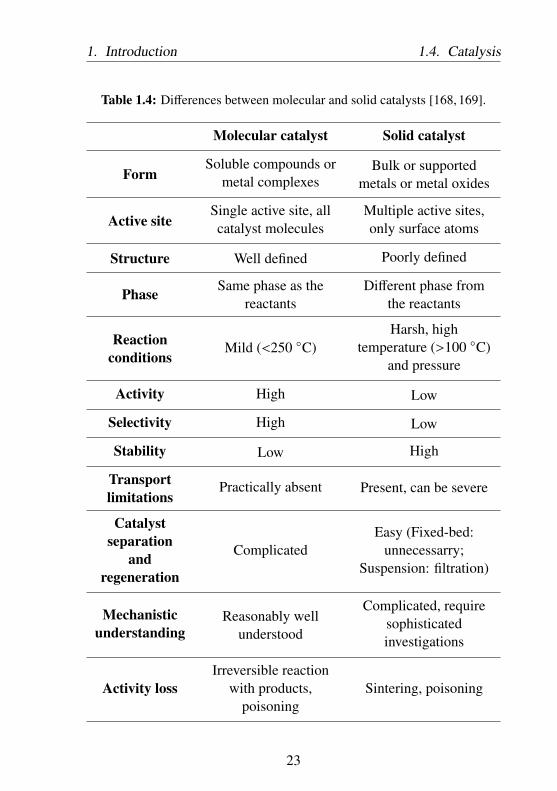
(immobilized molecular catalysts), which will be further discussed inChapter 3.There are some major differences between molecular and solid catalysisas illustrated in Table 1.4.
Process with Molecular Catalyst
In homogeneously catalyzed reactions, the catalysts, the starting mate-rials, and the products are present in the same phase. Each individualcatalyst molecule is a catalytically active species. When coupled witha high degree of dispersion or mixing, a molecular catalyst displays avery high activity. Molecular catalysts also allow for high selectivities atmild reaction conditions and low catalyst concentrations. High mobilityof each molecule, including the catalyst, during reaction ensures morecollisions with substrate molecules. However, due to the low stabilityof metal complexes, the reactions can only be performed up to tem-peratures below 250 ○C. In addition, laborious catalyst separation fromthe products, which sometimes demands complex processes such as dis-tillation or liquid-liquid extraction, hinders their industrial application.There are four main types of molecular catalysts:
• Acid and base catalysts
• Organocatalysts
• Biocatalysts (Enzymes, Cells, etc.)
• Transition metal catalysts, i.e. a transition metal atom as thecatalytic active centers surrounded by coordinating ligands.
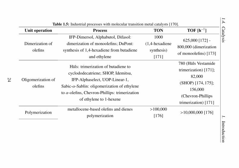
The classical transition metal catalysts (organometallic catalysts) areone of the most important type of molecular catalysts. Some large-scaleindustrial processes with molecular catalyst are listed in Table 1.5.
22
1. Introduction 1.4. Catalysis
Table 1.4: Differences between molecular and solid catalysts [168, 169].
Molecular catalyst Solid catalyst
FormSoluble compounds or
metal complexesBulk or supported
metals or metal oxides
Active siteSingle active site, allcatalyst molecules
Multiple active sites,only surface atoms
Structure Well defined Poorly defined
Phase Same phase as thereactants
Different phase fromthe reactants
Reactionconditions
Mild (<250 ○C)Harsh, high
temperature (>100 ○C)and pressure
Activity High Low
Selectivity High Low
Stability Low High
Transportlimitations
Practically absent Present, can be severe
Catalystseparation
andregeneration
ComplicatedEasy (Fixed-bed:
unnecessarry;Suspension: filtration)
Mechanisticunderstanding
Reasonably wellunderstood
Complicated, requiresophisticatedinvestigations
Activity lossIrreversible reaction
with products,poisoning
Sintering, poisoning
23
1.4.C
atalysis1.
Introduction
Table 1.5: Industrial processes with molecular transition metal catalysts [170].
Unit operation Process TON TOF [h−1]
Dimerization ofolefins
IFP-Dimersol, Alphabutol, Difasol:dimerization of monoolefins; DuPont:
synthesis of 1,4-hexadiene from butadieneand ethylene
1000(1,4-hexadiene
synthesis)[171]
625,000 [172] -800,000 (dimerizationof monoolefins) [173]
Oligomerization ofolefins
Hüls: trimerization of butadiene tocyclododecatriene; SHOP, Idemitsu,
IFP-Alphaselect, UOP-Linear-1,Sabic-α-Sablin: oligomerization of ethyleneto α-olefins, Chevron-Phillips: trimerization
of ethylene to 1-hexene
780 (Hüls Vestamidetrimerization) [171];
82,000(SHOP) [174, 175];
156,000(Chevron-Phillips
trimerization) [171]
Polymerizationmetallocene-based olefins and dienes
polymerization>100,000
[176]>10,000,000 [176]
24

1.Introduction
1.4.C
atalysis
Carbonylation
Reppe reactions; Monsanto: carbonylation ofmethanol to acetic acid;
Ruhrchemie/Rhone-Poulenc: propene to1-butanol and 2-ethylhexanol
1,400(methanol
carbonylation)[177]
400 (methanolcarbonylation) [177];
10,000 (propenehydroformylation)
[178]
HydrocyanationDuPont: adiponitrile from butadiene and
HCN644 [179, 180] 215 [179, 180]
Oxidation
cyclohexane oxidation; production ofcarboxylic acids (adipic and terephthalic
acid); Halcon: propylene oxide production;Wacker-Hoechst: selective ethylene
oxidation to acetaldehyde
95,000(cyclohexane
oxidation)[181, 182]
18,000 (cyclohexaneoxidation) [182]; 20
(ethyleneepoxidation) [183];
3,600 - 350,000(Wacker ethyleneoxidation) [184]
IsomerizationDuPont: Conversion of1,4-dichloro-2-butene to
3,4-dichloro-1-butene
450 (iron oxidenanoparticle)
[185, 186]
25

1.4.C
atalysis1.
Introduction
MetathesisDegussa-Hüls: octenenamer from
cyclooctene500 - 700 [187]
HydrogenationMonsanto L-Dopa process: asymmetrichydrogenation; Procatalyse: benzene to
cyclohexane; Takasago: L-menthol
20,000(L-dopa) [188];
400,000 (L-menthol) [170]
1,000 (L-dopa) [188];25,000
(L-menthol) [170,188]
26

1. Introduction 1.4. Catalysis
The reactivity of molecular transition metal catalysts depends on thecharacteristics of the central metal atoms (oxidation state, number ofd-electrons, coordination number and availability of free coordinationsites on the metal) and the attached ligands (steric and electronic proper-ties). The transition metal is usually in low oxidation state with partiallyfilled d and/or f orbitals. Nucleophilic ligands with available electronlone pairs (HOMO) donate electrons to the electrophilic metal (LUMO),forming a σ-bond to the metal center. In addition, the HOMO of tran-sition metal can also donate electrons into an empty π* antibondingorbital of the ligands (LUMO), a concept called π-backbonding. Someimportant ligands types in molecular transition metal catalysis are listedin Table 1.6The total amount of electron in the valence shells of transition metals(both the valence electrons of the metals and electron contribution ofthe ligands) dictates the stability or reactivity of the complexes, whichis described by the 18 valence electron (18-VE) rule. A metal complexthat has 18 valence electrons are typically stable, while a complex withfewer than 18 valence electrons, also called coordinatively unsaturatedcomplexes, tend to show enhanced reactivity. There are however somecases in which the 18-VE rule is violated:
• 16 e− complexes: low spin d8 metal ions such as Fe(0), Ru(0),Os(0), Co(I), Rh(I), Ir(I), Ni(II), Pd(II), Pt(II), Cu(III) and Au(III).
• complexes with bulky ligands: Ti(neopentyl)4 (8-VE), Cp2Ti(C2H4)(16-VE), V(CO)6 (17-VE), CpCr(CO)3 (17-VE), Pt(PtBu3)2 (14-VE), Co(norbornyl)4 (13-VE), [FeCp2]+ (17-VE)
• High spin complexes: CrCl3(THF)3 (15-VE), [Mn(H2O)6]+2 (17-
VE), [Cu(H2O)6]+2 (21-VE), [CrO4]–
2 (16-VE), Mo(−−NR)2Cl2 (12-VE)
27

1.4. Catalysis 1. Introduction
Table 1.6: Ligand types in molecular transition metal catalysts [189].
Ligand types Examples Electroncontribution
Hydride H– 1
Halogenides Cl–, Br–, I–, F– 1
Oxygen containingligands water, alcohols, ethers 2
Sulfur containingligands
mercaptans, thioethers 2
Nitrogen containingligands
amines, nitriles 2
NO1 (bent NO) or3 (linear NO)
Phosphorouscontaining ligands
phosphines PR3,phosphites P(OR)3
2
Carbon containingligands
alkyls, aryls 1
CO, alkenes, carbenes 2
allyls1 (η 1-allyls) or
3 (η 3-allyls)
carbynes, alkynes 3
dienes 4
cyclopentadienyls 5
aromatics 6
28

1. Introduction 1.4. Catalysis
• high VE complexes: Cobaltocene (19-VE), Nickelocene (20-VE),[Cu(H2O)6]+
2 (21-VE)
In addition to its ability to coordinate and/or activate a molecule, thetransition metal is also able to change the oxidation states and thecoordination numbers easily. These three distinctive features allowthe transition metal complex to undergo four fundamental reactions inorganometallic catalysis:
1.) Association and DissociationThe metal center can associate or coordinate a ligand or a sub-strate that enters a certain coordination distance. The ligand orsubstrate occupies a free coordination site of the metal and formsa coordination bond with the metal. Reversibly, the ligand canleave the coordination site, which is called dissociation. Thevalence electrons and the coordination number of the metal in-crease during association and decrease during dissociation. Inboth cases, the oxidation number of the metal remains constant.A special case of consecutive dissociation of one ligand and asso-ciation of another is called ligand exchange.
Ni(CO)4 Ni(CO)3
dissociation
association+ CO
VE=16CN=3ON=0
VE=18CN=4ON=0
Figure 1-11: Fundamental reaction in organometallic catalysis: Associationand Dissociation [190].
2.) Oxidative Addition and Reductive EliminationContrary to association and dissociation reactions, oxidative addi-tion and reductive elimination involve a change in oxidation state
29

1.4. Catalysis 1. Introduction
of the metal. During oxidative addition, the metal adds atoms ormolecules and at the same time undergoes formal oxidation. Onthe other hand, during reductive elimination, the metal is formallyreduced by eliminating ligands. Oxidative addition and reductiveelimination are both important steps in the initial and final phaseof a catalytic reaction.
Ir
ClPh3P
OC PPh3
H H+
oxidative addition
reductive elimination
Ir
HPh3P
OC PPh3Cl
H
VE=16CN=4ON=I
VE=18CN=6ON=III
Figure 1-12: Fundamental reaction in organometallic catalysis: OxidativeAddition and Reductive Elimination [190].
3.) Insertion and De-insertionInsertion is a crucial step to incorporate a certain substrate intoanother. Insertion demands substrates to be coordinated in cisposition. On the other hand, de-insertion or extrusion happenswhen a substrate split off into two molecules. In both cases, theoxidation state of the metal remains constant.
Mn(CO)5
CO insertion
CO deinsertion
Me Mn(CO)4
O
Me
Figure 1-13: Fundamental reaction in organometallic catalysis: Insertion andDe-insertion [190].
4.) Oxidative Coupling and Reductive CleavageIn oxidative coupling, the metal center merges two molecules with
30

1. Introduction 1.4. Catalysis
each other, forming a metallacycle, and as a result the oxidationstate of the metal increases. The reverse reaction, the reductivecleavage, split off the metallacycle into two molecules while theoxidation state decreases.
oxidative coupling
reductive cleavage
LnM LnM
Figure 1-14: Fundamental reaction in organometallic catalysis: OxidativeCoupling and Reductive Cleavage [190].
Different metal-ligand combinations have different preference to facil-itate a certain reaction with different selectivities. The electronegativ-ity of transition metals affects their preference to coordinate a certainmolecule [189, 191].Early transition metals groups III and IV are often found in a very highoxidation state, for example Zr(IV) or Ta(V). Due to low amount ofd-electrons, early transition metals in their highest oxidation state preferhardσ-donors (N, O, or F ligands) and will tend to coordinate π acceptorligands (for example CO, C6H6, or C2H4) weakly. On the other hand,early transition metals with lower oxidation states, such as d2 Zr(II) orTa(III), are very π basic and bind such ligands very strongly. With theexception being Ti, early transition metals display a very limited redoxcapability. Early transition metal complexes usually show a remarkableactivity in polymerization reactions.Transition metals of the groups V, VI, and VII, bind ligand strongly withnot very reactive metal carbon bonds. They prefer ligands with σ-donorand π-acceptor backbonding capabilities, for example CO. Due to manyaccessible oxidation states, they are especially suitable for redox reac-tions. Mid transition metal complexes are usually used in the oxidationas well as alkene and alkyne metathesis reactions.
31
1.4. Catalysis 1. Introduction
Similar to middle transition metals, late transition metals groups VIII,IX, and X are generally suitable for redox reactions. They exist either as18-VE or 16-VE (square planar) complex. Late transition metals preferσ-donor and weak π-acceptor ligands, such as phosphines. π back do-nation is less pronounced, resulting in positively-charged, coordinated πligands, which is very susceptible to nucleophilic attack. Coordinationwith C-ligands results in a weak metal carbon bonds with moderate re-activity, while coordination with O- or N-ligands generates weaker, yetreactive M-O or M-N bonds. Typical catalysis includes hydroformyla-tion, hydrogenation, hydrosilylation, isomerization and oligomerizationreactions.
I- < Br- < SCN- < Cl- < F- < OH-, ONO- < OH2 < NCS- < NCCH3 < NH3, py < NO2- < CN-, NO, CO
weak-field ligandsπ-donor ligands
high-spin complexes
strong-field ligandsπ-acceptor ligandslow-spin complexes
Figure 1-15: Examples of common ligands by field strength [189].
Moreover, 3d transition metals, especially early transition metals withlow d-electron counts, bind ligands weaker than 4d and 5d transitionmetals with high d electron density and usually tend to undergo 1 e−
redox changes instead of 2 e− redox changes. In addition, 3d transitionmetals with high oxidation states are generally not very stable withstrong oxidizing character. 4d and 5d transition metals with higheroxidation states are more stable and less oxidizing, allowing a morepronounced redox cycle.Ligands, the second part of a organometallic catalyst, can also affect thereactivity of the complex in two ways:
• Steric effects: depending on whether the ligand is coordinatedthrough a single donor atom (monodentate ligand) or through
32

1. Introduction 1.4. Catalysis
multiple donor atoms (chelating ligands), the accessibility of freecoordination site for a substrate and its stability can be influencedand thus affecting the metal site to favor a certain reaction. Thesteric demand of a ligand can be quantified and is known as theTolman cone angle Θ, for monodentate ligands, or ligand biteangle, for chelating ligands.
• Electronic effects: the nucleophilicity of the ligand affects theability of the metal to bind substrates. Strong σ-donor ligandsincrease the electron density of the metal atom, allowing strong πback donation to ligands and vice versa.
PF3 - P(OPh)3 - P(OMe)3 - PMe3 - PEt3 - PCy3 - P(tBu)3
electrophilic ligand
weak σ-donor ligands
strong π-donor ligands
nucleophilic ligand
strong σ-donor ligands
weak π-donor ligands
Figure 1-16: Some phosphine ligands with increasing nucleophilicity fromleft to right.
The combination of metal and ligand results in unique properties oforganometallic catalysts in binding and activating the substrates. Thevalence electrons of the organometallic complex define the strength andmode of bonding of the molecules while the ligand provides the sterichindrance neccessary to direct the selectivity of a reaction.
Process with Solid Catalyst
The most important features of solid catalysts are the stability, easyproduct separation and catalyst regeneration, which makes their indus-trial application attractive (Figure 1.7).
33
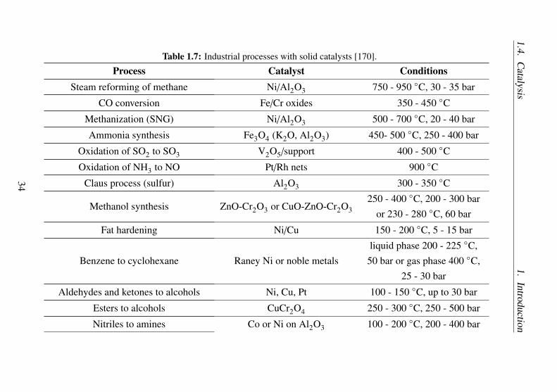
1.4.C
atalysis1.
Introduction
Table 1.7: Industrial processes with solid catalysts [170].
Process Catalyst ConditionsSteam reforming of methane Ni/Al2O3 750 - 950 ○C, 30 - 35 bar
CO conversion Fe/Cr oxides 350 - 450 ○CMethanization (SNG) Ni/Al2O3 500 - 700 ○C, 20 - 40 bar
Ammonia synthesis Fe3O4 (K2O, Al2O3) 450- 500 ○C, 250 - 400 bar
Oxidation of SO2 to SO3 V2O5/support 400 - 500 ○COxidation of NH3 to NO Pt/Rh nets 900 ○C
Claus process (sulfur) Al2O3 300 - 350 ○C
Methanol synthesis ZnO-Cr2O3 or CuO-ZnO-Cr2O3250 - 400 ○C, 200 - 300 bar
or 230 - 280 ○C, 60 bar
Fat hardening Ni/Cu 150 - 200 ○C, 5 - 15 bar
Benzene to cyclohexane Raney Ni or noble metalsliquid phase 200 - 225 ○C,
50 bar or gas phase 400 ○C,25 - 30 bar
Aldehydes and ketones to alcohols Ni, Cu, Pt 100 - 150 ○C, up to 30 bar
Esters to alcohols CuCr2O4 250 - 300 ○C, 250 - 500 bar
Nitriles to amines Co or Ni on Al2O3 100 - 200 ○C, 200 - 400 bar
34
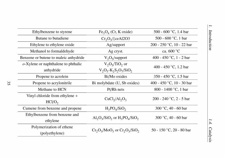
1.Introduction
1.4.C
atalysis
Ethylbenzene to styrene Fe3O4 (Cr, K oxide) 500 - 600 ○C, 1.4 bar
Butane to butadiene Cr2O3/{ceAl2O3 500 - 600 ○C, 1 bar
Ethylene to ethylene oxide Ag/support 200 - 250 ○C, 10 - 22 bar
Methanol to formaldehyde Ag cryst. ca. 600 ○CBenzene or butene to maleic anhydride V2O5/support 400 - 450 ○C, 1 - 2 bar
o-Xylene or naphthalene to phthalicanhydride
V2O5/TiO2 orV2O5-K2S2O7/SiO2
400 - 450 ○C, 1.2 bar
Propene to acrolein Bi/Mo oxides 350 - 450 ○C, 1.5 bar
Propene to acrylonitrile Bi molybdate (U, Sb oxides) 400 - 450 ○C, 10 - 30 bar
Methane to HCN Pt/Rh nets 800 - 1400 ○C, 1 bar
Vinyl chloride from ethylene +
HCl/O2CuCl2/Al2O3 200 - 240 ○C, 2 - 5 bar
Cumene from benzene and propene H3PO4/SiO2 300 ○C, 40 - 60 bar
Ethylbenzene from benzene andethylene
Al2O3/SiO2 or H3PO4/SiO2 300 ○C, 40 - 60 bar
Polymerization of ethene(polyethylene)
Cr2O3/MoO3 or Cr2O3/SiO2 50 - 150 ○C, 20 - 80 bar
35

1.4.C
atalysis1.
Introduction
Cracking of kerosene and residues ofatmospheric crude oil distillation to
produce gasolineAl2O3/SiO2 or zeolites 500 - 550 ○C, 1 - 20 bar
Hydrocracking of vacuum distillates toproduce gasoline and other fuels
MoO3/CoO/Al2O3 orNi/SiO2-Al2O3 or Pd zeolites
320 - 420 ○C, 100 - 200 bar
Hydrodesulfurization of crude oilfractions
NiS/WS2/Al2O3 orCoS/MoS2/Al2O3
300 - 450 ○C, 100 bar H2
Catalytic reforming of naphtha(high-octane gasoline, aromatics,
LPG)Pt/Al2O3 or bimetal/Al2O3 470 - 530 ○C, 13 - 40 bar H2
Isomerization of light gasoline(alkanes) and of m-xylene to
o/p-xylenePt/Al2O3 or Pt/Al2O3/SiO2 400 - 500 ○C, 20 - 40 bar
Demethylation of toluene to benzene MoO3/Al2O3 500 - 600 ○C, 20 - 40 bar
Disproportionation of toluene tobenzene and xylenes
Pt/Al2O3/SiO2 420 - 550 ○C, 5 - 30 bar
Oligomerization of olefins to producegasoline
H3PO4/kieselguhr orH3PO4/activated carbon
200 - 240 ○C, 20 - 60 bar
36

1. Introduction 1.4. Catalysis
Currently, solid catalysts still dominate 90% of all industrial processes[192]. Solid catalysts are divided into two main types:
• Bulk catalysts, in which the active sites are part of the catalyststructure (e.g. zeolites)
• Supported solid catalysts, in which the active sites are not part ofthe catalyst structure (e.g. transition metal catalyst supported onsilica)
Only surface atoms of a solid catalyst are accessible to the reactants andthus are catalytically active. In general, solid catalyzed reactions consistof several chemical and physical reaction steps (Figure 1-17):
1.) Diffusion of the educts through film diffusion layer to the catalystsurface.
2.) Diffusion of the educts into the pores.
3.) Adsorption of the educts on the inner surface of the pores.
4.) Chemical reaction on the active site.
5.) Desorption of the products from the catalyst surface.
6.) Diffusion of the products out of the pores.
7.) Diffusion of the products away from the catalyst through filmdiffusion layer and into the fluid phase.
Therefore, in heterogeneously catalyzed reactions, the effective reactionrate is influenced by many parameters, such as the thickness of the filmdiffusion layer, the bulk density of the catalyst, the pore structure, andthe mass transport rate of the reactants in the diffusion layer. Depend-ing on which parameter has the dominating influence on the effectivereaction rate, three different cases can be distinguished:
37

1.4. Catalysis 1. Introduction
12
3,4,5 6 7
Catalyst
Film diffusion
layer
Figure 1-17: Seven steps of heterogeneously catalyzed reaction.
• Film diffusion limitation: the diffusion rate in the fluid film is theslowest and the rate determining step for the reaction rate.
• Pore diffusion limitation: the diffusion rate in the pore is theslowest and rate determining step.
• Kinetic limitation: the chemical reaction rate is the slowest andrate determining step.
Heterogeneously catalyzed processes often require several process im-provements to enhance the effective reaction rate. For example, filmdiffusion limitation can be suppressed by increasing the velocity of thefluid in the reactor. In case of pore diffusion limitation, the ratio of theouter to the inner surface area can be improved by reducing the particlesize, thus shortens the pore diffusion path. In addition, all mass transportand kinetic limitation regimes can also be influenced by temperature ofthe reactions, obeying the Arrhenius law (Figure 1-18).
38

1. Introduction 1.4. Catalysis
ln r
eff
1/T
Film diffusion limitation
Pore diffusion limitation
Kinetic limitation
EA,eff ≤ 5 kJ/mol EA,eff = 𝐸𝐴
2 EA,eff = 𝐸𝐴
Figure 1-18: Effective reaction rate as a function of reaction temperature.
Heterogeneously catalyzed reactions proceed via chemisorption of theparticipating molecules at the active sites. There are two important"classical" reaction mechanisms in solid catalysis:
1.) Langmuir-Hinshelwood mechanismReactant A and B are adsorbed at different active sites of thecatalyst surface. The neighboring chemisorbed reactants A andB react with each other to give product C, which is then desorbedfrom the catalyst surface.
2.) Eley-Rideal mechanismOnly reactant A is chemisorbed at the catalyst surface. The reac-tant A reacts directly with B in the fluid phase to give product C,which is then desorbed from the catalyst surface.
39

1.4. Catalysis 1. Introduction
A B
B
AA B
Langmuir-Hinshelwood Eley-Rideal
AA BB
C
C
Figure 1-19: Langmuir-Hinshelwood mechanism (left) and Eley-Ridealmechanism (right).
40

1. Introduction 1.4. Catalysis
Despite several fundamental differences between molecular and solidcatalysis, reactions at solid catalysts can be related to those with organometal-lic catalystsThe activity of solid catalysts depends on the characteristicof the catalyst surface. Catalyst atoms with low coordination numbers,for example those at crystalline defects, may provide free accessiblecoordination sites for substrates resulting in enhanced reactivity duringcatalytic reaction [193]. Moreover, defects generate dangling bondswith different specific electron energy levels, which may affect the co-ordination and modes of bonding of molecules. A complex synergybetween structural and electronic properties of the catalyst surface re-sults in different types of defects (steps or kinks) to favor different reac-tions to take place. In addition, the electronic property of the catalystsis also determined by long range valence electron sharing over manysuccessive adjacent atoms. The surface of a solid catalyst can donate (n-semiconductors) or accept electrons (p-semiconductors) from adsorbedspecies, leading to anionic and cationic chemisorption respectively. Thedonor and acceptor levels of the catalyst can be tailored by introducingdopant. The ability to accept and donate electron allows the catalyst toundergo redox cycle. Lastly, the crystallographic plane of the catalystinfluences the geometry and surface density among others, which influ-ence the nature and strength of the interactions with the environmentand thus the chemistry of the atoms and molecules forming on thesurface. A correctly spaced group of atoms on surface may better ac-commodate a certain reactant molecules, and thus direct the selectivityof the reaction. While the fundamentals of the solid catalyst and themolecular transition metal catalyst may be similar, direct translation ofa homogeneous process with molecular catalyst to heterogeneous onewith solid catalyst is not trivial. Finding a solid catalyst system withsimilar steric and electronic properties of a molecular catalyst transition
41
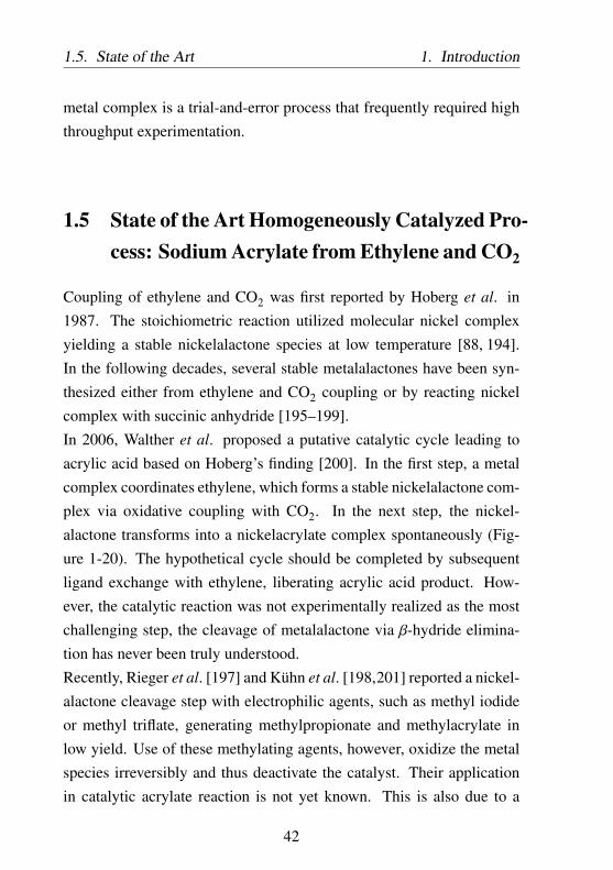
1.5. State of the Art 1. Introduction
metal complex is a trial-and-error process that frequently required highthroughput experimentation.
1.5 State of the Art Homogeneously Catalyzed Pro-cess: Sodium Acrylate from Ethylene and CO2
Coupling of ethylene and CO2 was first reported by Hoberg et al. in1987. The stoichiometric reaction utilized molecular nickel complexyielding a stable nickelalactone species at low temperature [88, 194].In the following decades, several stable metalalactones have been syn-thesized either from ethylene and CO2 coupling or by reacting nickelcomplex with succinic anhydride [195–199].In 2006, Walther et al. proposed a putative catalytic cycle leading toacrylic acid based on Hoberg’s finding [200]. In the first step, a metalcomplex coordinates ethylene, which forms a stable nickelalactone com-plex via oxidative coupling with CO2. In the next step, the nickel-alactone transforms into a nickelacrylate complex spontaneously (Fig-ure 1-20). The hypothetical cycle should be completed by subsequentligand exchange with ethylene, liberating acrylic acid product. How-ever, the catalytic reaction was not experimentally realized as the mostchallenging step, the cleavage of metalalactone via β-hydride elimina-tion has never been truly understood.Recently, Rieger et al. [197] and Kühn et al. [198,201] reported a nickel-alactone cleavage step with electrophilic agents, such as methyl iodideor methyl triflate, generating methylpropionate and methylacrylate inlow yield. Use of these methylating agents, however, oxidize the metalspecies irreversibly and thus deactivate the catalyst. Their applicationin catalytic acrylate reaction is not yet known. This is also due to a
42

1. Introduction 1.5. State of the Art
CO2
OH
O
Ni OH
O
Ni
NiO O
Ni
O
H
O
Ln
Ln
Ln
Ln
Figure 1-20: Hypothetical catalytic cycle leading to acrylic acid from CO2and ethylene according to Walther et al [200].
very challenging ethylene mediated liberation of the esters of acrylicacid [197].In addition, Bernskoetter et al. reported nickelalactone cleavage witha combination of Lewis acid and nitrogen-containing base [202]. TheLewis acid promotes ring opening through β-hydride elimination in thenickelalactone species, which readily forms an nickel acrylate complexupon contact with a base, such as tert-butylimino-tri(pyrrolidino)phos-phorane (BTPP). The application of the finding in catalytic reaction is,however, not yet realized. It can also be expected that a combinationof Lewis acid and Lewis base is only possible for a few very uniquesystems reported as frustrated Lewis pair, which further complicate thedevelopment of the catalytic cycle.Homogeneously catalyzed acrylate synthesis from CO2 and ethylene
43

1.5. State of the Art 1. Introduction
referred in this work will be based on the finding reported by Lim-bach et al. (Figure 1-21) [203, 204]. Ni(COD)2 forms nickel ethylenecomplex in the presence of a phosphine ligand and ethylene. Under
CO2
ONa
O
base-H
Ni(COD)2
PtBu2tBu2P
dtbpe
PNi
PONa
O
PNi
P
tBu2
tBu2
tBu2
tBu2
PNi
PtBu2
tBu2
O O
base
PNi
PtBu2
tBu2
O O
base Na
Na
Figure 1-21: Hypothetical catalytic cycle leading to acrylates from CO2 andethylene with 1,2-bis(di-tert-butylphosphino)-ethane (dtbpe)ligand [203].
CO2 pressure at high temperature, the ethylene complex forms a stablenickelalactone. The optimum pressure and temperature required fornickelalactone formation are greatly influenced by the phosphine ligand(Figure 1-22 and Table 1.8). The following cleavage of nickelalactoneto its corresponding acrylate complex is the most challenging step. Con-trary to the putative catalytic cycle of Walther et al., the nickelalactonecleavage can be achieved by introducing non-nucleophilic base to give
44

1. Introduction 1.5. State of the Art
P
P
PhPh
PhPh
PPh
Ph
PPh
Ph
P
P
PhPh
PhPh
dppm
dppe
dppp
P
P
tButBu
tButBu
PtBu
tBu
PtBu
tBu
P
P
tButBu
tButBu
dtbpm
dtbpe
dtbpp
Figure 1-22: List of ligands investigated by Limbach et al. for nickelalactoneformation [203]. dppm: 1,1-bis(diphenylphosphino)methane,dppe:1,2-bis(diphenylphosphino)ethane,dppp:1,3-bis(diphenylphosphino)propane,dtbpm:1,1-bis(di-tert-butylphosphino)methane,dtbpe:1,2-bis(di-tert-butylphosphino)ethane,dtbpp:1,3-bis(di-tert-butylphosphino)propane
45

1.5. State of the Art 1. Introduction
Table 1.8: Nickelalactone formation with various ligands investigated byLimbach et al. [203]. Solvent: THF, 2 bar ethylene, 6 bar CO2, 50○C, 72 hours.
6 bar CO2
Ni(COD)2 NiO O
Ln Ln
2 bar C2H4
THF-d8
Entry Ligand R Yield Nickelalactone [%]
1 dppm Ph 0
2 dppe Ph 0
3 dppp Ph 0
4 dtbpm tBu60 (only under ethylene and CO2
pressure, decomposes uponpressure release)
5 dtbpe tBu 35
6 dtbpp tBu 0
46
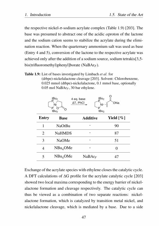
1. Introduction 1.5. State of the Art
the respective nickel-π-sodium acrylate complex (Table 1.9) [203]. Thebase was presumed to abstract one of the acidic αproton of the lactoneand the sodium cation seems to stabilize the acrylate during the elimi-nation reaction. When the quarternary ammonium salt was used as base(Entry 4 and 5), conversion of the lactone to the respective acrylate wasachieved only after the addition of a sodium source, sodium tetrakis[3,5-bis(trifluoromethyl)phenyl]borate (NaBArF).
Table 1.9: List of bases investigated by Limbach et al. for(dtbpe)-nickelalactone cleavage [203]. Solvent: Chlorobenzene,0.025 mmol (dtbpe)-nickelalactone, 0.1 mmol base, optionally0.05 mol NaBArF , 30 bar ethylene.
PNi
PONa
OtBu2
tBu2
PNi
PtBu2
tBu2
O O
4 eq. base∆T, PhCl
Entry Base Additive Yield [%]
1 NaOtBu - 90
2 NaHMDS - 87
3 NaOMe - 51
4 NBu4OMe - 0
5 NBu4OMe NaBArF 47
Exchange of the acrylate species with ethylene closes the catalytic cycle.A DFT calculations of ∆G profile for the acrylate catalytic cycle [203]showed two local maxima corresponding to the energy barrier of nickel-alactone formation and cleavage respectively. The catalytic cycle canthus be viewed as a combination of two separate reactions: nickel-alactone formation, which is catalyzed by transition metal nickel, andnickelalactone cleavage, which is mediated by a base. Due to a side
47
1.6. Process Design 1. Introduction
reaction of the alkoxide base with CO2 forming inactive semi-carbonate,Limbach et al. proposed a process divided into two separate steps.Nickelalactone is formed in the first step under ethylene and CO2 richatmosphere while nickelalactone cleavage step is conducted under CO2
free atmosphere.
1.6 The Alkoxide Base System - Process Design
The catalytic cycle described by Limbach et al. [203] utilized a molecu-lar catalyst, the nickel complex, and an alkoxide as base. A hypotheticalprocess with two separate steps has to be designed to prevent the alkox-ide base from forming inactive complexes with CO2.
Process 1.1 (two steps system according to Limbach et al. [203]):
Catalytic reaction
A solution of (dtbpe) and Ni(COD)2 (0.025 M) in organic solvent, suchas chlorobenzene or THF, is preheated and mixed with gas (ethylene :CO2 = 1:4) before entering the reactor. The autoclave reactor is fur-ther pressurized and heated to reach certain operating pressure (50 bar)and temperature (60 ○C). The reactor is run in three different operationmodes. In the first mode, the nickel complex forms a nickelalactonecomplex in the presence of ethylene and CO2.Since the formation of nickelalactone from ethylene and CO2 is stronglyaffected by the reaction equlibrium, full conversion can hardly be achieved.To maximize the space time yield, after reaching approximately 55 %conversion (2 hours), the reactor is switched to the second operatingmode: the reactor is depressurized for the subsequent nickelalactonecleavage. During depressurization, it is important to maintain sufficient
48

1. Introduction 1.6. Process Design
stirring to ensure complete removal of dissolved CO2 from the solvent.The ethylene-CO2 gas mixture can be further used to pressurize a sec-ond, parallel reactor. The alkoxide base NaOtBu (0.2 eq.) is addedinto the reactor, which is then immediately pressurized with 20 barof ethylene, heated at 45 ○C, and stirred for 1 hour, during which thebase mediated cleavage of the nickelalactone takes place. The operatingmodes 1 and 2 are repeated up to 18 times, after which, the reactor iscompletely depressurized (operating mode 3) and the reaction mixtureis fed into an extraction module, where the acrylate product is isolatedfrom the reaction mixture via water extraction. To increase efficiency,the heat from the product stream can be recuperated and used to preheatthe feed stream. Three different heat exchangers are proposed for theprocess: two heat exchangers to preheat the feed stream and one heatexchanger to preheat the recycled nickel complex stream.
Product isolation and reactants recycling
The sodium acrylate product is extracted from water with diethyl etherto improve the miscibility gap between the organic and aqueous phases.The liquid-liquid extraction process takes place at 25 ○C. The organicphase containing diethyl ether and the nickel complex solution in chloro-benzene is further vacuum distilled to separate the diethyl ether from thenickel complex solution, which can be recycled into the reactor. Diethylether is recovered and can be fed into the extraction column. The waterphase containing sodium acrylate product and tert-butanol, a conjugateacid of the NaOtBu, is further reprocessed by solvent stripping to isolatethe sodium acrylate as solid. The conjugate acid of alkoxide base,which forms an azeotrope with water, can be reclaimed, for example
49

1.6. Process Design 1. Introduction
Nickel complexSolvent
Water
Base+ NaOH or NaH
CO2Ethylene
Reactor3 operation modes
Extraction:Product separation
Nickel complexSolvent
Diethylether
Sodium acrylate
SolventStripping
100 °C, 0.3 bar
Pretreatmentwith NaOH or NaH
Alcohol/waterSeparation
CO2 Ethylene
35 °C
30 °C
Diethylether Separation:
Vacuum distillation
40 °C
45 °C
25 °C
25 °C
25 °C
25 °C
25 °C
TOF: 5.14 ·10-5 s-1
Figure 1-23: Process 1.1: Use of a molecular catalyst nickel complex andCO2-sensitive alkoxide base in catalytic acrylate reaction.
50

1. Introduction 1.6. Process Design
Mode 1: lactone formation (CO2 rich)
Mode 2: lactone cleavage(CO2 poor)
Ethylene CO2
Base
Mode 3: depressurization
Ethylene
20 bar ethylene
60 °C, 2 h
45 °C, 1 h
10 bar ethylene40 bar CO2
Figure 1-23: (cont.)
51

1.6. Process Design 1. Introduction
via heterogeneous azeotropic batch distillation with cyclohexane as anentrainer [205]. The alkoxide base can be regenerated by reacting itsconjugate acid with NaH or NaOH.The sophisticated process with alternating operation modes and a chal-lenging recycling of the alkoxide base may not be suitable for industrialapplication. Multi-reactors system operating alternately can be usedto maximize the space time yield of the product while recycling thereactants as well as the ethylene and CO2 gases. Due to the instabilityof the nickel complex, the process described above has to be carried outstrictly oxygen free with low-temperature extraction and recycling steps.All solvents, including water and diethyl ether for product extraction,have to be degassed before use to remove dissolved oxygen.While the system utilizing a homogeneous nickel complex and an alkox-ide base was reported as the only working catalytic reaction of ethyleneand CO2 leading to sodium acrylate [203], the system was limited byseveral factors:
1.) Side reactions of the alkoxide base with CO2 yielding the sodiumcarbonate derivates.
2.) The formation of conjugate acid byproduct of the alkoxide base,which deactivates the Ni catalytic species and can contaminate thesodium acrylate product.
3.) Two-pot process: the formation of nickelalactone with the subse-quent, separate nickelalactone cleavage step.
4.) Sophisticated product separation and base recycling processes.
In this work, three different system concepts are proposed to addressthe limitations of the state-of-the-art process reported by Limbach etal [203]:
52

1. Introduction 1.6. Process Design
• Homogeneous process with a molecular nickel complex as cata-lyst and amine-NaH base systems (Chapter 2).
• Heterogeneous process with an immobilized nickel complex ascatalyst and amine-NaH base systems (Chapter 3).
• Heterogeneous process with a molecular nickel complex as cata-lyst and an immobilized base (Chapter 4).
53

1.6. Process Design 1. Introduction
54

Chapter 2
Homogeneous Process
2.1 Liquid Base - NaH System
Catalytic acrylate synthesis from CO2 and ethylene requires an addi-tional electrophilic agent or non-nucleophilic base which can cleave thestable nickelalactone intermediate. Homogeneous process utilizing non-nucleophilic bases have reported a working catalytic cycle. However,most active alkoxide base reported by Limbach et al. [203] are limitedby their low solubility in reaction solvent and their side reactions withCO2 yielding their respective sodium carbonate derivates [206]. Addi-tionally, they form conjugate acid byproduct (alcohols), which deacti-vates the Ni catalyst species and can contaminate the sodium acrylateproduct. Moreover, due to the high degree of solubility of the alco-hols in water, a sophisticated recycling of the base is required after theextraction process. Liquid or readily-soluble non-nucleophilic bases,which do not react with CO2 or other reactants, are of huge interestand would benefit the catalytic process. Furthermore, high mobility ofliquid bases would improve the collision probability of the base withthe nickelalactone intermediate, which will be important especially in
55

2.1. Liquid Base - NaH System 2. Homogeneous Process
processes utilizing solid catalyst. In the preliminary experiments, thecombination of a liquid, non-nucleophilic base namely a phosphazenewith NaH as cation (Na+) source were tested and displayed activity innickelalactone cleavage. It was also found that tertiary amine baseswork in combination with NaH. Interestingly this base system work alsoin the presence of CO2 pressure, which paves a way to a much betterprocess described in the following subchapter. Some bases with aminefunctionality investigated in this work are illustrated in Figure 2-2.
CO2
ONa
O
amine
Ni(COD)2
PCy2PCy2
dcpe
PNi
PONa
O
PNi
P
Cy2
Cy2
Cy2
Cy2
PNi
PCy2
Cy2
O O
amine
PNi
PCy2
Cy2
O O
amine Na
Na
Figure 2-1: Hypothetical catalytic cycle leading to acrylates from CO2 andethylene with 1,2-bis(dicyclohexylphosphino)-ethane (dcpe)ligand and amine-NaH base system.
In this work, 1,2-bis(dicyclohexylphosphino)-ethane (dcpe) will be themain ligand investigated (Figure 2-1). The commercially available dcpe,
56

2. Homogeneous Process 2.1. Liquid Base - NaH System
EtN
Et
EtN
N
TEA(18.83)
DBU(24.34)
Me2N P NMe2
N
NMe2
P NN
Me2N P NN
NMe2
N
N
tBu tBu
tBu
P1(26.98)
BEMP(27.63)
P2(33.49)
P NMe2
NMe2
NMe2
N P NN
N
tBu
P NMe2
NMe2
NMe2
PNMe2
Me2NNMe2
P4(42.7)
P NMe2
NMe2
Me2N
N
N,N-diethylaniline(6.57)
N
N,N-dimethylaniline(5.1)
N
N
4-(dimethylamino)pyridine(17.95)
C8H17 NC8H17
C8H17
Trioctylamine
Figure 2-2: Active bases investigated in this work. pKA values in acetonitrilein parentheses. Exception: N,N-dimethylaniline andN,N-diethylamine pKA values in water [207–209].P1:tert-butyl-tris(dimethylamino)phosphorane,P2:1-tert-butyl-2,2,4,4,4-pentakis(dimethylamino)-2λ5,4λ5
− catenadi(phosphazene),P4:1-tert-butyl-4,4,4-tris(dimethylamino)-2,2-bis[tris(dimethylamino)-phosphoranylidenamino]-2λ5,4λ5
− catenadi(phosphazene),BEMP:2-tert-butylimino-2-diethylamino-1,3-dimethylperhydro-1,3,2-diazaphosphorine,DBU:1,8-diazabicyclo[5.4.0]undec-7-ene, TEA:triethylamine.
57

2.1. Liquid Base - NaH System 2. Homogeneous Process
which was reported to readily form a stable (dcpe)-nickelalactone fromethylene and CO2 [91, 203], is currently the most cost-efficient ligand.Control experiments with dcpe ligand and alkoxide base confirmed theformation of sodium acrylate, justifying its application as a model ligandfor the catalytic investigations.
2.1.1 Process Design Options
A process with amine-NaH base system would simplify the process 1.1described before (Figure 1-23).Process 1.2 (the lactone formation and cleavage in one reaction stepFigure 2-3): Use of an amine-NaH base system, which is active underCO2, allows both the formation and cleavage of the nickelalactone tobe carried out in one-pot process. The process design is based on theexperimental data discussed in the next section (Subchapter 2.1.2), with0.2 mmol Ni(COD)2, 0.2 mmol dcpe ligand, 50 eq. triethylamine asbase, 500 eq. NaH as cation (Na+) source, and 50 mL THF as solvent at100 ○C and 5 bar ethylene and 10 bar CO2, yielding 101.75 mg sodiumacrylate (TON = 5.41, Entry 21 Table 2.1). Contrary to process 1.1(based on the publication of Limbach et al. [203]) described before, theprocess with amine-NaH base system was run with ethylene : CO2 ratioof 1:2 and THF as solvent. These parameters was obtained from thereaction optimization carried out at CaRLa with several ligands [210]and are used in this work for easy comparison between project partners.
Catalytic reaction
Dissolved nickel complex in organic solvent THF is preheated andmixed with gas (ethylene : CO2 = 1:2), triethylamine and NaH beforeentering the reactor. The autoclave reactor is further pressurized andheated to reach certain operating pressure (15 bar) and temperature (100
58

2. Homogeneous Process 2.1. Liquid Base - NaH System
○C). Contrary to the process described before (Figure 1-23), the reactorwith amine-NaH system is run with all components present in the one-pot reaction. The nickel complex forms a nickelalactone complex in thepresence of ethylene and CO2, which is subsequently cleaved with theamine-NaH combination. The amine-NaH base system is stable duringthe catalytic reaction, without any side reaction with CO2. The catalyticcycle proceeds until the process is stopped. The reactor is depressurized,after which, the mixture is fed into an extraction module, where theacrylate product is isolated via water extraction. To increase efficiency,the heat from the product stream can be recuperated and used to preheatthe feed stream. Three different heat exchangers are proposed for theprocess: two heat exchangers to preheat the feed stream and one heatexchanger to preheat the recycled nickel complex stream.
Product isolation and reactants recycling
The sodium acrylate product is extracted from water with diethyl etherto improve the miscibility gap. The liquid-liquid extraction processtakes place at 25 ○C. The organic phase containing diethyl ether andnickel complex solution is further vacuum distilled to separate the di-ethyl ether from the nickel complex solution in THF, which can berecycled into the reactor. The diethyl ether is recovered and can befed into the extraction column. The water phase containing sodiumacrylate product and triethylamine, is further reprocessed by evaporatingthe solvent to isolate the sodium acrylate as solid. Triethylamine can bereclaimed via distillation. Compared to the process described before, theprocess with amine-NaH system significantly reduces several steps andmakes base recycling more efficient. Multi-reactors system operatingalternately can be used to maximize the space time yield of the productwhile recycling the reactants as well as the ethylene and CO2 gases.
59

2.1. Liquid Base - NaH System 2. Homogeneous Process
Nickel complexSolvent
Water
Base+ NaOH or NaH
CO2Ethylene
Reactor2 operation modes
Extraction:Product separation
Nickel complexSolvent
Diethylether
Sodium acrylate
SolventStripping
100 °C, 0.3 bar
Pretreatmentwith NaOH or NaH
Base/waterSeparation
CO2 Ethylene
60 °C
50 °C
Diethylether Separation:
Vacuum distillation
90 °C
100 °C
25 °C
25 °C
25 °C
25 °C
25 °C
TOF: 7.51 ·10-5 s-1
Figure 2-3: Process 1.2: Use of a molecular catalyst nickel complex andCO2-stable amine-NaH base in catalytic acrylate reaction.
60

2. Homogeneous Process 2.1. Liquid Base - NaH System
Mode 1: lactone formation and cleavage
Base
Mode 2: depressurization
CO2Ethylene
100 °C, 20 h
Figure 2-3: (cont.)
61

2.1. Liquid Base - NaH System 2. Homogeneous Process
Due to the instability of the nickel complex, the process described abovehas also to be carried out strictly under oxygen-free conditions with low-temperature extraction and recycling steps. All solvents, including waterand diethyl ether for product extraction, have to be degassed before useto remove oxygen.
2.1.2 Types of Bases
The effectivity of the bases during catalytic reaction was studied withthe same process parameters for the sake of comparison using THFas solvent, 5 bar ethylene and 10 bar CO2 at 80 ○C (Figure 2-4 andTable 2.1). All bases with tertiary amine function investigated in thiswork displayed a very promising activity. During catalytic reaction,the tertiary amine function may facilitate sodium attacking the lactoneforming the respective acrylate complex.
62

2.H
omogeneous
Process2.1.
Liquid
Base
-NaH
System
0.94
0.35
1.25
0.84
0.63
1.18
1.41
2.65
3.93
0.88
2.03
2.99
2.35
1.57
2.12
3.28
N,N-diethylaniline
N,N-dimethylaniline
4-(dimethylamino)pyridine
Triethylamine
TBD
DBU
BEMP
P4
P2
P1
0.0 0.5 1.0 1.5 2.0 2.5 3.0 3.5 4.0
TON [-]
TON [-] 72 h TON [-] 18 h
Figure 2-4: Effectivity of different liquid bases during catalytic reaction. Parameters: 0.2 mmol Ni(COD)2, 0.22 mmoldcpe, 2.5 mmol base (except for P4: 1 mmol), 10 mmol NaH, 5 bar ethylene, 10 bar CO2, 45 mL THF, T =
80 ○C, t = 18 or 72 hours. See also Figure 2-6 for reactions with trioctylamine at optimized reactionparameters.
63

2.1. Liquid Base - NaH System 2. Homogeneous Process
On the other hand, secondary or primary amines are supposed to be in-active due to their side reaction with CO2 (Figure 2-5, forming insoluble,catalytic-inactive carbamate (for example 1,5,7-Triazabicyclo[4.4.0]dec-5-ene (TBD) yielded TON = 0).
N
N
NH
N
N
N
OHO
CO2
Figure 2-5: Side reaction of triazabicyclo[4.4.0]dec-5-ene (secondary amine)with CO2 [211].
Of huge importance is the high activity of trioctylamine (Figure 2-6 Ta-ble 2.1 Entry 23) as well as N,N-dimethylaniline and N,N-diethylaniline(Table 2.1 Entry 24-25), which are hardly soluble in water (Solubilityin water 0.0001 g/L, 1.2 g/L, and 0.13 g/L respectively) [212]. Theapplication of such bases would not only improve the recyclability of thebase itself, but also would simplify the process significantly. Conceptualprocess design utilizing such bases is further discussed in Subchapter2.1.5.
1 1 . 8 54 . 4 7
5 . 3 4
T r i o c t y l a m i n e
T r i e t h y l a m i n e
0 1 2 3 4 5 6 7 8 9 1 0 1 1 1 2T O N [ - ]
Figure 2-6: Effectivity of different liquid bases during catalytic reaction.Parameters: 0.2 mmol Ni(COD)2, 0.22 mmol dcpe, 10 mmolbase, 10 mmol NaH, 10 bar ethylene, 20 bar CO2, 45 mL THF, T= 100 ○C, t = 18 or 72 hours.
64
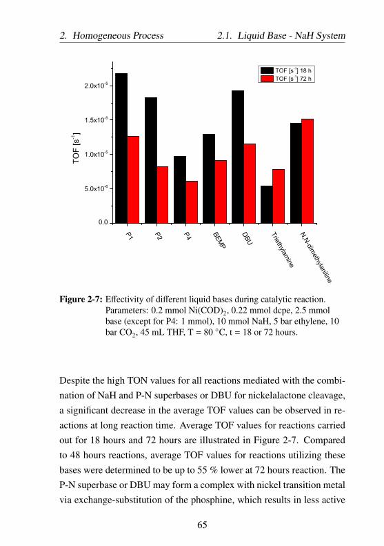
2. Homogeneous Process 2.1. Liquid Base - NaH System
P1 P2 P4 BEMP
DBU
Triethylamine
N,N-dimethylaniline
0.0
5.0x10⁻⁶
1.0x10⁻⁵
1.5x10⁻⁵
2.0x10⁻⁵TO
F [s
-1]
A
TOF [s-1] 18 h TOF [s-1] 72 h
Figure 2-7: Effectivity of different liquid bases during catalytic reaction.Parameters: 0.2 mmol Ni(COD)2, 0.22 mmol dcpe, 2.5 mmolbase (except for P4: 1 mmol), 10 mmol NaH, 5 bar ethylene, 10bar CO2, 45 mL THF, T = 80 ○C, t = 18 or 72 hours.
Despite the high TON values for all reactions mediated with the combi-nation of NaH and P-N superbases or DBU for nickelalactone cleavage,a significant decrease in the average TOF values can be observed in re-actions at long reaction time. Average TOF values for reactions carriedout for 18 hours and 72 hours are illustrated in Figure 2-7. Comparedto 48 hours reactions, average TOF values for reactions utilizing thesebases were determined to be up to 55 % lower at 72 hours reaction. TheP-N superbase or DBU may form a complex with nickel transition metalvia exchange-substitution of the phosphine, which results in less active
65

2.1. Liquid Base - NaH System 2. Homogeneous Process
nickel-amine complex formation. The resulting nickel-amine complexhas the difficulty to undergo reaction with CO2, which leads to loweramount of nickelalactone available for the catalytic reaction. In addition,less active base would be available for the nickelalactone cleavage. Onthe other hand, nickel transition metal with phosphine ligand is barelyable to be substituted with triethylamine or dialkylaniline base, resultingin a constant average TOF observed for this system, even at long reac-tion time. The application of triethylamine or dialkylaniline can thusimprove the catalyst lifetime compared to superbases investigated at theinitial phase of this project. Further investigations with in situ NMR willallow to elucidate the side reactions postulated here.
66

2.H
omogeneous
Process2.1.
Liquid
Base
-NaH
System
Table 2.1: Effectivity of different liquid bases during catalytic reaction. Parameters: 0.2 mmol Ni(COD)2, 0.22 mmoldcpe, 45 mL THF, cation source: NaH. Entries illustrated in Figure 2-4 and Figure 2-6 are marked in blue
Entry BasenBase nCation T pC2H4
pCO2TON [-]
[mmol] [mmol] [○C] [bar] [bar] t = 18h t = 72h t = 100h1 P1 2.5 0 80 5 10 0 0 0
2 P1 0 10 80 5 10 0 0 0
3 P1 2.5 10 40 5 10 0 0 0
4 P1 2.5 10 60 5 10 0.3
5 P1 2.5 10 70 5 10 0.41
6 P1 2.5 10 80 5 10 1.41 3.28 3.11
7 P1 2.5 10 90 5 10 1.57
8 P1 2.5 10 100 5 10 2.09 3.98
9 P1 2.5 10 120 5 10 0.91
10 P1 0.2 10 80 5 10 1 2.63
11 P1 1 10 80 5 10 0.66 2.8
12 P1 2.5 100 80 5 10 1.07
13 P1 5 10 80 5 10 1.5 3.39
14 P2 2.5 10 80 5 10 1.18 2.12
67

2.1.L
iquidB
ase-N
aHSystem
2.H
omogeneous
Process
15 BEMP 2.5 10 80 5 10 0.84 2.35
16 P4 1 10 80 5 10 0.63 1.57
17 DBU 2.5 10 80 5 10 1.25 2.99
18 triethylamine 2.5 10 80 5 10 0.35 2.03
19 triethylamine 100 100 80 5 10 0.94 5.99
20 triethylamine 2.5 10 100 5 10 3.56
21 triethylamine 10 10 100 5 10 5.41 4.06
22 triethylamine 10 10 100 10 20 5.34
23 trioctylamine 10 10 100 10 20 4.47 11.85
24 N,N-dimethylaniline 2.5 10 80 5 10 0.94 3.93
25 N,N-diethylaniline 2.5 10 80 5 10 2.65
26 4-(dimethylamino)pyridine 2.5 10 80 5 10 0.88
27 TBD 2.5 10 80 5 10 0 0 0
68
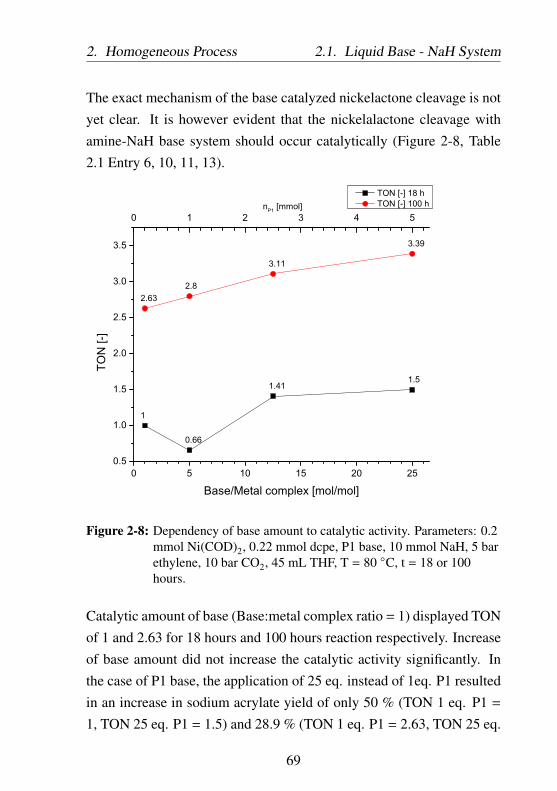
2. Homogeneous Process 2.1. Liquid Base - NaH System
The exact mechanism of the base catalyzed nickelactone cleavage is notyet clear. It is however evident that the nickelalactone cleavage withamine-NaH base system should occur catalytically (Figure 2-8, Table2.1 Entry 6, 10, 11, 13).
0 5 10 15 20 250.5
1.0
1.5
2.0
2.5
3.0
3.5
0 1 2 3 4 5
1
0.66
1.411.5
2.632.8
3.11
3.39
nP1 [mmol]
TON
[-]
Base/Metal complex [mol/mol]
TON [-] 18 h TON [-] 100 h
Figure 2-8: Dependency of base amount to catalytic activity. Parameters: 0.2mmol Ni(COD)2, 0.22 mmol dcpe, P1 base, 10 mmol NaH, 5 barethylene, 10 bar CO2, 45 mL THF, T = 80 ○C, t = 18 or 100hours.
Catalytic amount of base (Base:metal complex ratio = 1) displayed TONof 1 and 2.63 for 18 hours and 100 hours reaction respectively. Increaseof base amount did not increase the catalytic activity significantly. Inthe case of P1 base, the application of 25 eq. instead of 1eq. P1 resultedin an increase in sodium acrylate yield of only 50 % (TON 1 eq. P1 =
1, TON 25 eq. P1 = 1.5) and 28.9 % (TON 1 eq. P1 = 2.63, TON 25 eq.
69

2.1. Liquid Base - NaH System 2. Homogeneous Process
P1 = 3.39) for 18 hours and 100 hours reaction time respectively (Table2.1 Entry 10 and 13).
2.1.3 Effect of the Reaction Temperature
The nickelalactone formation is highly temperature dependent and fa-vored at mild temperature of about 50 ○C for the dtbpe ligand [203]. Atlower temperature, the nickelalactone formation is thermodynamicallylimited, while at higher temperature the nickel complex decomposesforming the corresponding ligand dioxide or monooxide of biphos-phines (Figure 2-9).
PNi
PCy2
Cy2
O O PNi
PCy2
Cy2
P
PCy2
Cy2
O
P
PCy2
Cy2
OO
Ni(0)+ +
Figure 2-9: Decomposition of (dcpe)-nickelalactone yielding dcpemonooxide, dcpe dioxide, and Ni(0).
The catalytic acrylate formation can be considered as two separate re-action steps with nickel catalyzed lactone formation in the first step andbase mediated lactone cleavage in the second step. As consequences,three different operating temperature regions can thus be derived (Figure2-10):
• Reaction temperature below 60 ○C: no sodium acrylate formationcan be detected in reactions performed at 40 ○C and below. At aslightly higher temperature, the yield of sodium acrylate begins toincrease with the temperature.
• Reaction temperature between 60 and 100 ○C: linear dependencybetween the sodium acrylate yield and the reaction temperature.
70

2. Homogeneous Process 2.1. Liquid Base - NaH System
In this region, the rates of formation and cleavage of the nickel-alactone increase with the temperature.
• Reaction temperature above 100 ○C: nickelalactone begins todecompose (nickelalactone decomposition is faster than nickel-alactone formation and cleavage). The decomposition is irre-versible and lead to discontinuation of the catalytic cycle.
0
0.5
1
1.5
2
2.5
0 20 40 60 80 100 120 140
TO
N 1
8h
[-]
Temperature [°C]
Sodium Acrylate
Propionic acid
Sodium Formate
Region I Region II Region III
Figure 2-10: Temperature dependency of acrylate catalytic reaction.Parameters: 0.2 mmol Ni(COD)2, 0.22 mmol dcpe, 2.5 mmolP1, 50 mmol NaH, 5 bar ethylene, 10 bar CO2, 45 mL THF, t =
18 hours (Table 2.1 Entry 3-9).
The amounts of the byproducts, the propionic acid and sodium formate,are constant at around TON 0.5 and 0.03 respectively and are not in-fluenced by reaction temperature. The detected propionic acid can be
71

2.1. Liquid Base - NaH System 2. Homogeneous Process
formed via the hydrolysis of a fraction of (dcpe)-nickelalactone duringthe work-up (extraction with water) (Figure 2-11). These findings areconsistent with the stability of the nickelalactone itself. The nickel-alactone is formed already at low temperature of 40 ○C and decomposesat high temperature. At reaction temperature of 120 ○C, the amount ofpropionic acid in the reaction mixture was below the detection limit ofthe NMR measurement, which can be related to the scarce availabilityof the nickelalactone. The highest selectivity in sodium acrylate at 79% can thus be achieved in catalytic reaction performed at 100 ○C. Ahigher selectivity in sodium acrylate could be reached by preventing thehydrolysis of the nickelalactone. This can be realized for example byseparating the molecular catalyst and the nickelalactone intermediatebefore contacting the reaction mixture with water. A representativeprocess concept will be discussed in Chapter 4.
PNi
PCy2
Cy2
O O PNi
PCy2
Cy2
H2O OHOH
O
OH+
Figure 2-11: Hypothetical hydrolysis of (dcpe)-nickelalactone with waterduring extraction to give propionic acid.
2.1.4 Effect of the Cation Sources
In addition to the amine base, cation sources such as NaH are crucialfor the catalytic cycle as they provide the Na cations and form an ac-tive species with amine basic system for the nickelalactone cleavage.Control experiments which only use base or only NaH did not yieldany sodium acrylate (Table 2.1 Entry 2). The interaction between theamine base and the Na+ cation (resulting in ammonium like compound)
72

2. Homogeneous Process 2.1. Liquid Base - NaH System
may improve the availability of Na+ cation, thus increasing the collisionprobability between nickelalactone intermediate and Na+ during thenickelalactone cleavage. During the cleavage, Na+ is stoichiometricallyconsumed while the amine base is not (Figure 2-12). Further in-situstudy is necessary to confirm these findings. NaH was the most active
PNi
PONa
OCy2
Cy2
PNi
PCy2
Cy2
O O PNi
PCy2
Cy2
O O amine
NaH
Na
H
H-
amine
H2
amine
Figure 2-12: Hypothetical cleavage of (dcpe)-nickelalactone with amine-NaHbase system to give sodium acrylate.
cation provider as substitution of NaH with LiH (Table 2.2 Entry 8:TON 1.13), KH (Table 2.2 Entry 10: TON 1.49), or NaHMDS (Table2.2 Entry 6: TON 0.45) resulted in only 35%, 50%, and 14% of themaximum yield of acrylate derivatives observed for NaH (Table 2.2Entry 1: TON 3.28 for 72 hours reaction time). Utilization of othercation sources, such as CaH2 (Table 2.2 Entry 9), alkali carbonates(Table 2.2 Entry 3, 4, 12 - 14, and 16), alkali salts (Table 2.2 Entry 3 - 5,11, and 16), or highly insoluble NaNH2 (Table 2.2 Entry 15), combinedwith amine base did not deliver acrylate derivative product. Catalyticactivity was achieved only with monovalent cations, Li+, Na+, and K+.The effectivity of the cation source can be related to the Lewis acidstrength and the size of the cation. Weak Lewis acid sodium cation isreported to be able to lower the energy barrier of β-hydride eliminationfrom a nickelalactone [213]. Among alkali cations investigated in thiswork, Na+ is the most effective cation for the nickelalactone cleavage.While K+ is weaker Lewis acid than sodium, its bulky cationic radius(138 pm) may hinder coordination with lactone species during β-hydride
73

2.1. Liquid Base - NaH System 2. Homogeneous Process
elimination, resulting in its lower activity. On the other hand, utilizationof LiH instead of NaH yielded 50 % less acrylate product. This is due tothe lattice energies of alkali hydrides which decreases progressively asthe size of the metal cation increases, and as consequences, the stabilityof these hydrides decreases from LiH to KH [214]. The higher thestability of a cation source, the lower the amount of free cation availableduring the cleavage of the nickelalactone. Further investigation assistedwith DFT calculations is required to elucidate the exact mechanism, inwhich the Lewis acid promotes β-hydride elimination. The addition of
0.51
0.47
0.35
1.18
1.41
0.45
1.1
1.13
1.12
1.49
2.03
2.12
3.28
0.0 0.5 1.0 1.5 2.0 2.5 3.0 3.5
P1 only
P1/LiCl
P1/NaHMDS
P1/Cs2CO3
P1/Na2CO3
P1/Li2CO3
P1/CaH2
NEt3/KH
P1/NaH
NEt3/NaH
P1/KH
P2/NaH
TON [-]
TON [-] 72 h TON [-] 18 h
P1/LiH
P2/LiH
Figure 2-13: Effectivity of different liquid base - additive systems duringcatalytic reaction. Parameters: 0.2 mmol Ni(COD)2, 0.22 mmoldcpe, 2.5 mmol base, 50 mmol additive, 5 bar ethylene, 10 barCO2, 45 mL THF, T = 80 ○C, t = 18 or 72 hours.
74
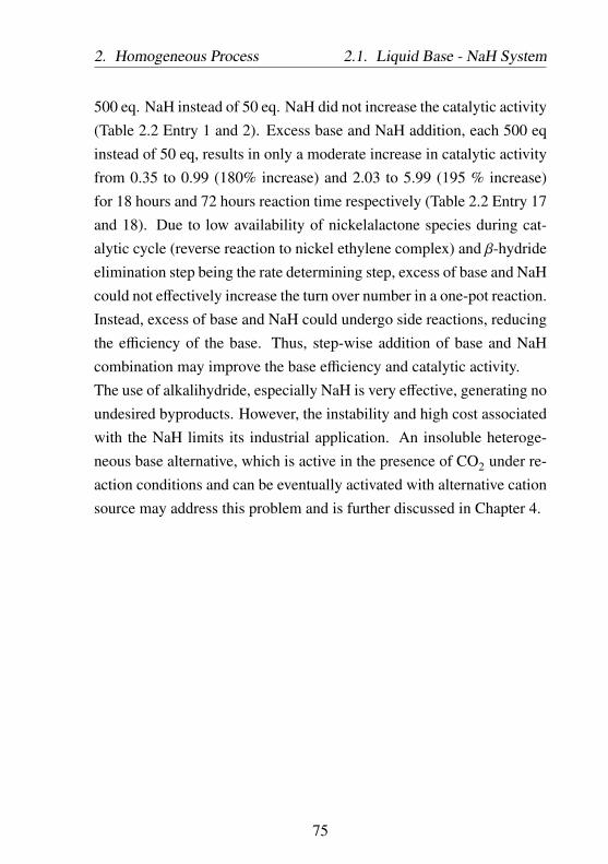
2. Homogeneous Process 2.1. Liquid Base - NaH System
500 eq. NaH instead of 50 eq. NaH did not increase the catalytic activity(Table 2.2 Entry 1 and 2). Excess base and NaH addition, each 500 eqinstead of 50 eq, results in only a moderate increase in catalytic activityfrom 0.35 to 0.99 (180% increase) and 2.03 to 5.99 (195 % increase)for 18 hours and 72 hours reaction time respectively (Table 2.2 Entry 17and 18). Due to low availability of nickelalactone species during cat-alytic cycle (reverse reaction to nickel ethylene complex) and β-hydrideelimination step being the rate determining step, excess of base and NaHcould not effectively increase the turn over number in a one-pot reaction.Instead, excess of base and NaH could undergo side reactions, reducingthe efficiency of the base. Thus, step-wise addition of base and NaHcombination may improve the base efficiency and catalytic activity.The use of alkalihydride, especially NaH is very effective, generating noundesired byproducts. However, the instability and high cost associatedwith the NaH limits its industrial application. An insoluble heteroge-neous base alternative, which is active in the presence of CO2 under re-action conditions and can be eventually activated with alternative cationsource may address this problem and is further discussed in Chapter 4.
75

2.1.L
iquidB
ase-N
aHSystem
2.H
omogeneous
Process
Table 2.2: Effectivity of different cation sources during catalytic reaction. Parameters: 0.2 mmol Ni(COD)2, 0.22 mmoldcpe, 45 mL THF, base: P1, P2, or triethylamine (NEt3).
Entry BasenBase Cation
nCation T pC2H4pCO2
TON [-][mmol] [mmol] [○C] [bar] [bar] t = 18h t = 72h t = 100h
1 P1 2.5 NaH 10 80 5 10 1.41 3.28 3.11
2 P1 2.5 NaH 100 80 5 10 1.07
3 P1 5 NaBArF+Na2CO3 0.11+10 80 5 10 0 0 0
4 P1 2.5 NaBArF+Na2CO3 1+10 80 5 10 0 0 0
5 P1 2.5 NaBArF+NaH 0.2+10 80 5 10 0 0 1.16
6 P1 2.5 NaHMDS 10 80 5 10 0.45
7 P1 2.5 NaHMDS+NaH 10+10 80 5 10 0.46
8 P1 2.5 LiH 10 80 5 10 1.13
9 P1 2.5 CaH2 10 80 5 10 0 0 0
10 P1 2.5 KH 10 80 5 10 0.47 1.49 0
11 P1 2.5 LiCl 10 80 5 10 0 0 0
12 P1 2.5 LiOH 5 80 5 10 0 0 0
13 P1 2.5 Li2CO3 5 80 5 10 0 0 0
14 P1 2.5 Cs2CO3 2 80 5 10 0 0 0
76

2.H
omogeneous
Process2.1.
Liquid
Base
-NaH
System
15 P1 2.5 NaNH2 10 80 5 10 0 0 0
16 P2 2.5 NaBArF+Na2CO3 0.11+10 80 5 10 0 0 0
17 P2 2.5 LiH 10 80 5 10 1.1
18 NEt3 10 NaH 10 80 5 10 0.35 2.03
19 NEt3 100 NaH 100 80 5 10 0.94 5.99
20 NEt3 10 NaH 10 100 10 20 5.34
21 NEt3 10 KH 10 100 10 20 0.51 1.12
77

2.1. Liquid Base - NaH System 2. Homogeneous Process
2.1.5 Improvement in Process Design
Table 2.3: List of active bases and their solubility in water and THF.
BaseSolubility in water
[M] [212]Solubility in THF
[M]
tert-butanol miscible 3.53
Phenol 0.89 0
Triethylamine 1.31 2.35
DBU 3.23 ⋅ 10−2 0
N,N-dimethylaniline 9.9 ⋅ 10−3 1.79
N,N-diethylaniline 8.71 ⋅ 10−4 1.15
Trioctylamine 2.83 ⋅ 10−7 0
Base recyclability during the extraction process can be improved byutilizing hardly water-soluble amines: aliphatic amines with long chainor aromatic amines. After complete water removal, organic phase isseparated during extraction containing nickel complex and base and canbe directly used for the next catalytic cycle. Contrary to process 1.1 andprocess 1.2 described before, the process utilizing water-insoluble liquidbase would only require a simple extraction process to separate theproduct and recycle the base from the reaction mixture, thus reducingthe investment and operational costs.Process 1.3: Similar to process 1.2, the process design is based on theexperimental data with 0.2 mmol (dcpe)-nickelalactone catalyst precur-sor, 50 eq. trioctylamine as base, 50 eq. NaH as cation (Na+) source, and50 mL THF as solvent at 100 ○C and 10 bar ethylene and 20 bar CO2,yielding 155.54 mg sodium acrylate (TON = 8.27, Entry 10 Table 2.4).
78

2. Homogeneous Process 2.1. Liquid Base - NaH System
Catalytic reaction
Dissolved nickel complex in organic solvent is preheated and mixedwith gas (ethylene : CO2 = 1:2), trioctylamine, and NaH base beforeentering the reactor. The autoclave reactor is further pressurized andheated to reach certain operating pressure (15 bar) and temperature (100○C). In a one-pot reaction, the nickel complex forms a nickelalactonecomplex in the presence of ethylene and CO2, which is subsequentlycleaved with the trioctylamine-NaH combination. The catalytic cycleproceeds until the process is stopped. After the reactor is depressurized,the mixture is subsequently fed into an extraction module, where theacrylate is separated from the reaction mixture via water extraction.Similar to previous processes, the heat from the product stream can berecuperated and used to preheat the feed stream.
Product isolation and base recycling
The sodium acrylate product is extracted from water with diethyl etherto improve the miscibility gap. The liquid-liquid extraction processtakes place at 25 ○C. The organic phase containing diethyl ether, tri-octylamine, and nickel complex solution is further vacuum distilled toseparate the diethyl ether from the nickel complex solution, which canbe recycled into the reactor. The diethyl ether is recovered and canbe fed into the extraction column. The water phase containing sodiumacrylate product is further reprocessed by solvent stripping to isolate thesodium acrylate as solid. The trioctylamine remains in the organic phasecan be directly transferred, along with nickel complex, to the reactor.Compared to the two processes 1.1 and 1.2 (Figure 1-23 and 2-3) de-scribed before, the process with trioctylamine-NaH system does not re-quire a specific base recycling process. Multi-reactor systems operatingalternately can be used to maximize the space time yield of the product.
79

2.1. Liquid Base - NaH System 2. Homogeneous Process
Nickel complexSolvent
Water
BaseNaH
CO2Ethylene
7
Reactor2 operation modes
Extraction:Product separation
Nickel complexSolvent
Base
Diethylether
Sodium acrylate
CO2 Ethylene
60 °C
50 °C 90 °C
100 °C
25 °C
25 °C
25 °C
25 °C
Diethylether Separation:
Vacuum distillation
SolventStripping
100 °C, 0.3 bar
TOF: 1.15 ·10-4 s-1
Figure 2-14: Process 1.3: Use of a molecular catalyst nickel complex andwater-insoluble base in catalytic acrylate reaction.
80

2. Homogeneous Process 2.1. Liquid Base - NaH System
Mode 1: lactone formation and cleavage
Mode 2: depressurization
CO2Ethylene
100 °C, 20 h
Figure 2-14: (cont.)
81

2.2. Nickelalactone 2. Homogeneous Process
Due to the instability of the nickel complex, the process described hasto be carried out strictly oxygen free with low-temperature extractionand recycling steps. All solvents, including water and diethyl ether forproduct extraction, have to be degassed before use to remove dissolvedoxygen, which would complicate industrial application.
2.2 Nickelalactone as Starting Point in the Cat-alytic Cycle
The acrylate reaction comprises the formation of nickelalactone inter-mediate, which is catalyzed by a transition metal complex, and thecleavage of this intermediate, which is mediated by a base. In the caseof one-pot reaction, such as Process 1.2 (Figure 2-3) and 1.3 (2-14)described before, the presence of both catalyst Ni(COD)2, biphosphineligand, amine base, and NaH at the beginning of the reaction could beproblematic. Since Ni(COD)2-ligand in situ complexation is a slow pro-cess, readily oxidizable phosphine ligand as well as unstable Ni(COD)2
and its side reaction with other reactants are to be expected leading toa reduction of the amount of active species for the catalytic reaction.NaH may form NaOH with trace water, which coordinates to the tran-sition metal nickel complex. This can be avoided by introducing analternative nickel complex precursor, the nickelalactone complex, whichis also an intermediate of the catalytic process. The nickelalactone canbe separately prepared, for example via ligand exchange of (tmeda)-nickelalactone with biphosphine ligand (Figure 2-15) [200,215]. Ligandexchange with (tmeda)-nickelalactone is currently the most convenientroute to obtain (dcpe)-nickelalactone in high yield (74.8 %, compared topreparation via oxidative coupling of CO2 and ethylene, which is only
82

2. Homogeneous Process 2.2. Nickelalactone
around 15 %). Since only catalytic amounts of (dcpe)-nickelalactoneis needed, its preparation via more costly ligand exchange route (1gram (dcpe)-nickelalactone = ca. 110 €, price calculated from theprice of each chemicals needed Sigma Aldrich catalog in March 2014)instead of via oxidative coupling of CO2 and ethylene (1 gram (dcpe)-nickelalactone = ca. 50 €) can be justified and will represent only afraction of the final price of the sodium acrylate product in hypotheti-cal industrial process with several thousands TON. The application of
N
NNi
OO P
Cy2
Cy2P
NiO
OPCy2
PCy2
+
N
N+
Figure 2-15: Preparation of (dcpe)-nickelalactone species via ligandexchange.
stable nickelalactone species as catalyst precursor improves the overallefficiency of the one-pot process. The use of nickelalactone as precursorsignificantly increased the TON of the catalytic cycle by approximatelyup to six times for triethylamine-NaH base systems (Figure 2-16). Theimprovement in catalytic activity is especially pronounced in 72 h re-actions, underlining the amount of active nickel species in the longterm. In case of catalytic reactions with triethylamine-NaH system,substitution of Ni(COD)2-dcpe catalyst system with pre-formed (dcpe)-nickelalactone resulted in an increase of the catalytic activity from 0.94to 5.53 (588 %) and from 4.06 to 18.84 (464 %) for 20 hours and 72hours reaction time respectively. Constant TOF values for both reactionsmediated with triethylamine-NaH with either 20 hours or 72 hours reac-tion time can be observed: in case of (dcpe)-nickelalactone at around7.5⋅10−5 s−1 and for Ni(COD)2-dcpe precursors 1.5⋅10−5s−1 (Figure2-17). This indicates that both the nickel complex catalyst and the
83

2.2. Nickelalactone 2. Homogeneous Process
8.27
5.53
16.91
18.84
12.88
4.47
0.94
2.09
11.85
4.06 3.98
0
5
10
15
20
TON 20h [-] TON 72h [-]
TON
[-]
(dcpe)-Nickelalactone Ni(COD)2 + dcpe
0
5
10
15
20
50 eq.trioctylamine
50 eq.triethylamine
100 eq. P1 50 eq.trioctylamine
50 eq.triethylamine
12.5 eq. P1
Figure 2-16: Nickelalactone as precursor for the catalytic cycle. Parameters:0.2 mmol Ni(COD)2 and 0.22 mmol dcpe or 0.2 mmol(dcpe)-nickelalactone, 100 eq. NaH, 10 bar ethylene, 20 barCO2, 45 mL THF, T = 100 ○C, t = 20 or 72 hours.
84

2. Homogeneous Process 2.2. Nickelalactone
0.0
2.0x10⁻⁵
4.0x10⁻⁵
6.0x10⁻⁵
8.0x10⁻⁵
1.0x10⁻⁴
1.2x10⁻⁴
TOF [s-1] 20 h TOF [s-1] 72 h
TOF
[s-1]
(dcpe)-Nickelalactone Ni(COD)2 + dcpe
0.0
2.0x10⁻⁵
4.0x10⁻⁵
6.0x10⁻⁵
8.0x10⁻⁵
1.0x10⁻⁴
1.2x10⁻⁴
50 eq.trioctylamine
50 eq.triethylamine
50 eq.trioctylamine
50 eq.triethylamine
Figure 2-17: Nickelalactone as precursor for the catalytic cycle. Parameters:0.2 mmol Ni(COD)2 and 0.22 mmol dcpe or 0.2 mmol(dcpe)-nickelalactone, 100 eq. NaH, 10 bar ethylene, 20 barCO2, 45 mL THF, T = 100 ○C, t = 20 or 72 hours.
85

2.2. Nickelalactone 2. Homogeneous Process
triethylamine-NaH system retain their original activities, even at longreaction time. Both the formation and cleavage of the nickelalactoneoccured at similar constant rate. The TOF for (dcpe)-nickelalactone cat-alyzed reaction is six times higher than that for reaction with Ni(COD)2-dcpe precursors.On the other hand, in the reactions with trioctylamine, a decrease inTOF at long reaction time can be observed. In reactions with (dcpe)-nickelalactone as catalyst precursor, TOF value declines from 1.15⋅10−4
s−1 for 20 hours catalytic reaction to about 6.52⋅10−5 s−1 in 72 hourscatalytic reaction. Possible explanation may be the high effectivity ofthe trioctylamine itself (TON for 20 hours reaction is 8.27 while TONfor 72 hours reaction is 16.91, Table 2.4 Entry 10). Thus, the overallreaction is limited by the amount of nickelalactone during catalytic reac-tion. Trioctylamine-NaH system cleaves the nickelalactone intermediateas soon as it is formed. Since the catalytic reaction was started withnickelalactone intermediate, short reaction time would result in higheraverage TOF value. At long reaction time, however, the nickelalactoneformation is the rate determining step, limiting the overall reaction,which leads to lower average TOF value. In reactions with Ni(COD)2-dcpe as catalyst precursor, TOF value declines from 6.2⋅10−5 s−1 for20 hours catalytic reaction to about 4.6⋅10−5 s−1 in 72 hours catalyticreaction. Further investigations with in situ NMR may confirm andelucidate the exact reaction limitation.Similar to catalytic reactions utilizing a combination of Ni(COD)2 anddcpe precursor, the base amount present during catalytic reaction didnot significantly improve the catalytic activity (Figure 2-18 and Table2.4 Entry 3 - 7). An increase in triethylamine amount from 0.5 eq. to25 eq., 100 eq., or 200 eq. only yield TON of 5.38 (Entry 6), 5.53(Entry 3), and 6.04 (Entry 7) respectively. It is also confirmed that
86

2. Homogeneous Process 2.2. Nickelalactone
the nickelalactone cleavage with amine-NaH base system is catalytic inhomogeneous base. Catalytic reaction with only 0.5 eq. of triethylaminebase provided sodium acrylate with a TON of 4.7 (Table 2.4 Entry 5).On the other hand, in reactions with KH as cation (K+) source, anincrease in triethylamine amount results in a decrease in the yield ofsodium acrylate (Entry 8 and 9). Catalytic reactions with 25 eq. and50 eq. triethylamine-KH base system yielded sodium acrylate withTON of 2.2 and 0.73 respectively. The results also affirmed previousfinding that weak Lewis acid NaH is the most suitable cation sourcesfor nickelalactone cleavage (Subchapter 2.1.4).
0 50 100 150 2000
1
2
3
4
5
6
4.7
5.38 5.53
6.04
TON
[-]
Amine/Metal complex [mmol/mmol]
TON [-] 20 h
Figure 2-18: Dependency of base amount to catalytic activity. Parameters:(dcpe)-nickelalactone precursor, triethylamine base, NaH cationsource, 45 mL THF, 10 bar ethylene, 20 bar CO2, T = 100 ○C, t= 20 hours.
87

2.2.N
ickelalactone2.
Hom
ogeneousProcess
Table 2.4: Use of (dcpe)-nickelalactone as catalyst precursor. Parameters: 10 bar ethylene, 20 bar CO2, 45 mL THF,temperature = 100 ○C, base: P1, triethylamine (NEt3), or trioctylammine (TOA).
Entryn(dcpe)−nickelalactone Base
nBase Base/Metal complexCation
nCation TON [-][mmol] [mmol] [mmol/mmol] [mmol] t = 20h t = 72h
1 0.1 P1 10 100 NaH 10 15.06
2 0.1 P1 10 100 NaH 10 12.88
3 0.1 NEt3 10 100 NaH 10 5.53 18.84
4 0.1 NEt3 10 100 NaH 10 4.44
5 0.2 NEt3 0.1 0.5 NaH 10 4.7
6 0.2 NEt3 5 25 NaH 5 5.38
7 0.1 NEt3 20 200 NaH 20 6.04
8 0.2 NEt3 10 50 KH 10 0.73
9 0.2 NEt3 5 25 KH 5 2.2
10 0.2 TOA 10 50 NaH 10 8.27 16.91
88
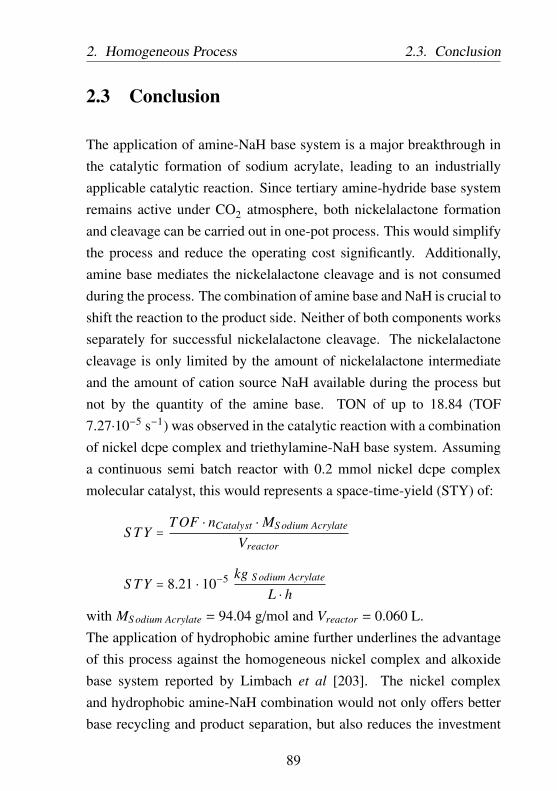
2. Homogeneous Process 2.3. Conclusion
2.3 Conclusion
The application of amine-NaH base system is a major breakthrough inthe catalytic formation of sodium acrylate, leading to an industriallyapplicable catalytic reaction. Since tertiary amine-hydride base systemremains active under CO2 atmosphere, both nickelalactone formationand cleavage can be carried out in one-pot process. This would simplifythe process and reduce the operating cost significantly. Additionally,amine base mediates the nickelalactone cleavage and is not consumedduring the process. The combination of amine base and NaH is crucial toshift the reaction to the product side. Neither of both components worksseparately for successful nickelalactone cleavage. The nickelalactonecleavage is only limited by the amount of nickelalactone intermediateand the amount of cation source NaH available during the process butnot by the quantity of the amine base. TON of up to 18.84 (TOF7.27⋅10−5 s−1) was observed in the catalytic reaction with a combinationof nickel dcpe complex and triethylamine-NaH base system. Assuminga continuous semi batch reactor with 0.2 mmol nickel dcpe complexmolecular catalyst, this would represents a space-time-yield (STY) of:
S TY =TOF ⋅ nCatalyst ⋅ MS odium Acrylate
Vreactor
S TY = 8.21 ⋅ 10−5 kg S odium Acrylate
L ⋅ hwith MS odium Acrylate = 94.04 g/mol and Vreactor = 0.060 L.The application of hydrophobic amine further underlines the advantageof this process against the homogeneous nickel complex and alkoxidebase system reported by Limbach et al [203]. The nickel complexand hydrophobic amine-NaH combination would not only offers betterbase recycling and product separation, but also reduces the investment
89

2.3. Conclusion 2. Homogeneous Process
costs greatly. TON of up to 16.91 (TOF 6.52⋅10−5 s−1) was observedin the catalytic reaction with a combination of nickel dcpe complexand trioctylamine-NaH base system. While the space-time-yield in thereaction utilizing hydrophobic amine is slighly lower than that withtriethylamine-NaH base combination, the process profitability of thatwith hydrophobic amine is enhanced by the lower separation and recyclecosts.
90

Chapter 3
Heterogeneous Process withImmobilized Complex
3.1 Theory
Over the past few decades, huge number of ligands and their transitionmetal complexes have been developed with far higher selectivity andactivity compared to their heterogeneous counterparts. Despite thisremarkable success, solid catalysts still dominate 90% of all chemicalprocesses in the chemical and petrochemical industries [192]. Highercost of metal-ligand system, cost- and energy-extensive separation, andthe crucial catalyst recovery required in processes utilizing molecularcatalysts are the main concern for their application in industrial largescale production. One prominent example is the hydroformylation oflower alkenes with cobalt catalyst. The separation of the cobalt metalfrom the low-boiling aldehydes can be achieved via simple distillation[216].
91

3.1. Theory 3. Heterogeneous Process
This sparks a growing interest in both academia and industry, to de-velop immobilized molecular catalysts, which combine the fast ratesand high selectivity of molecular catalysts with the easy recovery ofsolid catalysts. There are several concepts to immobilized molecularcatalysts [217–222]:
• Steric hindrance in porous systems ("ship in bottle" concept):Steric constraint can be introduced by assembling a catalyticallyactive complex inside the cages of porous support or by buildingthe framework surrounding the complex. The size of the metalcomplex relative to the dimension of the cages is the decisivefactor in the stability of the catalyst and may also contribute toselectivity, activity and kinetics of the reaction. In addition, thedimension of the cages and the pore opening can also induceshape selectivity phenomenon in (micro-)porous catalyst.
• Non-covalent interactions due to physisorption (van der Waalsinteraction) and Ion Exchange (Electrostatic interactions): Non-covalent interactions offer a relatively easy preparation strategy,for example via a simple impregnation procedure. Due to weakinteractions between ligand and support, the prepared catalystsoften suffer from extensive leaching, especially during catalyticreactions, when solvents and/or substrates tend to be competi-tively adsorbed and replace the immobilized catalyst.
• Grafting: In grafting, one or more groups of the support surfaceare chemically bonded to a metal center. The covalent bond in-creases the stability of the catalyst, but also results in electronsharing between the metal center and the surface, which modifies
92

3. Heterogeneous Process 3.1. Theory
the whole metal complex properties (coordination number, oxida-tion state, or symmetry).
• Anchoring (tethering): Alternatively, metal complex can be cova-lently anchored by connecting to the support surface with a seriesof covalent bonds. Long linker between the metal complex andsupport ensures no electron sharing between the metal center andthe surface group, thus the metal complex may retain its proper-ties.
Both covalent immobilization concepts, grafting and anchoring, are themost synthetically demanding strategies, yet offering the strongest bondbetween the complex and support. For successful immobilization, theyoften require synthetic functionalization of the support. In case of an-choring, the immobilized molecular catalyst can retain its properties,thus similar high catalytic activity to the not-immobilized molecularcatalyst.In the development of such hybrid catalysts, disadvantages observed inboth solid and molecular catalysis can not be neglected: limited contactbetween the reactants in the liquid phase and the active sites at the sur-face of the catalyst, generally observed in solid catalysis, and leachingof the metal component. Parallel adjustment of the catalytic processfrom the perspective of engineering as well as the process parametersthemselves, is vital and should not be overlooked.The study of ligand immobilization in this work will be strictly focusedon anchoring metal complex with 1,2-bis(dicyclohexylphosphino)-ethane(dcpe) ligand, specifically at either the carbon atom position at thebridge or the cyclohexyl substituents (Figure 3-1). The commerciallyavailable bidentate dcpe ligand was reported to yield nickelalactone witha good solubility in common solvents [91]. In the experiments withamine-NaH base system, dcpe also showed a decent activity with TON
93

3.1. Theory 3. Heterogeneous Process
CO2
ONa
O
amine
Ni(COD)2
PCy2PCy2
dcpe
PNi
PONa
O
PNi
P
Cy2
Cy2
Cy2
Cy2
PNi
PCy2
Cy2
O O
amine
PNi
PCy2
Cy2
O O
amine Na
Na
Figure 3-1: Hypothetical catalytic cycle leading to acrylates from CO2 andethylene with immobilized1,2-bis(dicyclohexylphosphino)-ethane (dcpe) ligand andamine-NaH base system.
94

3. Heterogeneous Process 3.2. Process Design Options
of up to 18.84 with triethylamine-NaH base combination and Ni as metalcenter (Table 2.4 Entry 3).
3.2 Process Design Options
From the process engineering point of view, homogeneously catalyzedprocess for acrylate production is very challenging. It requires a sophis-ticated and energy-intensive product separation step, during which thereadily oxidizable catalyst may be deactivated upon contact with waterused for extraction. In stark contrast, the heterogeneously catalyzedprocess offers several advantages. The application of solid catalystallows continuous operation of the catalytic reaction. The process canbe designed so that the catalyst remains catalytically active in the re-actor while allowing the reaction solvent containing dissolved sodiumacrylate product to be continuously isolated. This would avoid anyunintentional oxidation of the air-sensitive nickel complex as well asincrease the space time yield and reduce the operational cost.Process 2 (immobilized catalyst): The process design is based on theexperimental data discussed in the next section 3.4 (Table 3.10 Entry8): an immobilized (dcpe)-nickel complex with polystyrene support(loading: 0.075 mmol dcpe for each gram immobilized catalyst), 260eq. triethylamine or trioctylamine, 260 eq. NaH as cation (Na+) source,and 50 mL THF as solvent with operating temperature of 100 ○C and10 bar ethylene and 20 bar CO2. The preparation of immobilized ligandwill be further discussed in the next section. The immobilized catalystcan be introduced into the reactor in two ways:
• introduction of immobilized ligand and Ni(COD)2 into the reactoror
95

3.2. Process Design Options 3. Heterogeneous Process
Immobilized Nickel complex
Solvent
Water
CO2Ethylene
Reactorcontinuous mode
100 °C
Extraction:Product separation
SolventBase
Diethylether
Sodium acrylate
Sodium acrylateSolvent
Base
BaseNaOH or NaH
Pretreatmentwith NaOH or NaH
CO2 Ethylene
60 °C
50 °C 80 °C
100 °C
25 °C
25 °C
25 °C
25 °C
SolventStripping
100 °C, 0.3 bar
Diethylether Separation:
Vacuum distillation
TOF: 5.48 ·10-6 s-1
Figure 3-2: Process 2: Use of immobilized molecular catalyst andwater-insoluble base in catalytic acrylate reaction.
96

3. Heterogeneous Process 3.2. Process Design Options
• introduction as the stable key intermediate, the lactone species,analog to description in section 2.2.
In the latter approach, the lactone species can be prepared via ligand ex-change with (tmeda)-nickelalactone either separately before the reactionor directly in situ. The exact approach will be discussed in the followingsection.
Catalytic reaction
The immobilized catalyst along with base is suspended in the reactionsolvent THF, preheated, and mixed with amine and NaH before enteringthe reactor. Ethylene and CO2 pressures are each 10 bar and 20 barrespectively. During the catalytic reaction, the operating pressure andtemperature of the autoclave reactor are kept at 30 bar with ethylene toCO2 ratio of 1:2 and temperature of 100 ○C. Stirring with 2000 rpm isimportant to ensure sufficient contact probability between the reactantsin the fluid phase and the catalytic active site on the solid material.
Product isolation and recycling of the reactants
A part of the liquid is continuously fed into an extraction module, wherethe acrylate product is isolated via water extraction. Similar to theprevious processes described before, the sodium acrylate product is ex-tracted from water with diethyl ether to improve the miscibility gap. Theliquid-liquid extraction process is conducted at 25 ○C. The organic phasecontaining diethyl ether, trioctylamine, and nickel complex solution isfurther vacuum distilled to separate the diethyl ether from the nickelcomplex solution, which can be recycled into the reactor. The diethylether is recovered and can be fed into the extraction column. The water
97

3.3. Catalyst Design via Anchoring 3. Heterogeneous Process
phase containing sodium acrylate product is further reprocessed by sol-vent stripping to isolate the sodium acrylate as solid. The trioctylamineremaining in the organic phase can be directly transferred, along withthe nickel complex, to the reactor. Multi-reactors system operating inparallel can be used to further maximize the space time yield of theproduct.
3.3 Catalyst Design via Anchoring
Covalent immobilization of molecular catalysts to (in)organic materialsvia anchoring is one of the most popular concept for catalyst immo-bilization, especially in the fine chemical synthesis. Ideally, anchoredcatalysts should offer high stability and re-usability without leachingwhile at the same time display the same catalytic activities as theirhomogeneous counterparts. The character of immobilized catalyst de-pends on the linker, which connects the metal complex and the support.With increasing length of the linker, any unintentional interactions ofthe immobilized complex with the support can be minimized and theimmobilized catalyst will become more mobile and more similar inactivity to its homogeneous counterpart. This would affect the catalyticactivity and product selectivity during the reaction. Use of a short linkermay lower the catalytic activity or even lead to catalyst deactivation dueto steric constraints of the support materials, leading to low accessibilityof the active site. However, a very long flexible linker can lead to ahigher risk of the metal complex interacting with solid matrix and beingchemisorbed (Figure 3-3).In addition, the support material and the linker should display sufficient
98
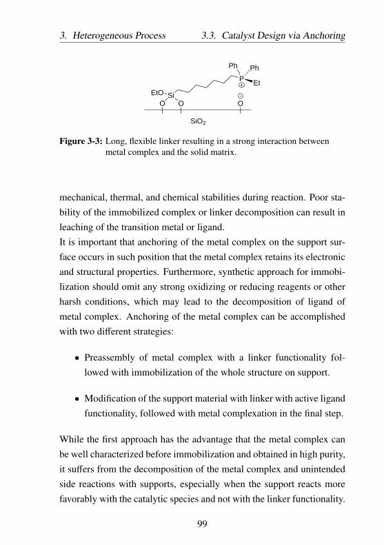
3. Heterogeneous Process 3.3. Catalyst Design via Anchoring
O O
SiO2
OSiEtO
P
Ph
Et
Ph
Figure 3-3: Long, flexible linker resulting in a strong interaction betweenmetal complex and the solid matrix.
mechanical, thermal, and chemical stabilities during reaction. Poor sta-bility of the immobilized complex or linker decomposition can result inleaching of the transition metal or ligand.It is important that anchoring of the metal complex on the support sur-face occurs in such position that the metal complex retains its electronicand structural properties. Furthermore, synthetic approach for immobi-lization should omit any strong oxidizing or reducing reagents or otherharsh conditions, which may lead to the decomposition of ligand ofmetal complex. Anchoring of the metal complex can be accomplishedwith two different strategies:
• Preassembly of metal complex with a linker functionality fol-lowed with immobilization of the whole structure on support.
• Modification of the support material with linker with active ligandfunctionality, followed with metal complexation in the final step.
While the first approach has the advantage that the metal complex canbe well characterized before immobilization and obtained in high purity,it suffers from the decomposition of the metal complex and unintendedside reactions with supports, especially when the support reacts morefavorably with the catalytic species and not with the linker functionality.
99

3.3. Catalyst Design via Anchoring 3. Heterogeneous Process
In the second strategy, the step-wise functionalization, the linker-func-tionalized support can be prepared in large quantity, a part of whichcan be separately anchored with different metal complexes, easily re-sulting in a potentially large and diverse catalyst library. The step-wisefunctionalization also avoids decomposition of the unstable metal com-plex, commonly observed when preformed metal complex is directlyanchored. Contrary to the first strategy, the step-wise functionalizationmay generate several side products on the surface of the support. Thisresults in several structures on the surface, thus preventing the construc-tion of a single-sited solid catalyst. Nevertheless, due to the addedstability and versatility, the second approach, the step-wise function-alization, is widely employed to prepare immobilized catalyst and willbe further discussed in this chapter.Depending on how the active ligand component is formed, the secondapproach can be further differentiated into two synthetic strategies (Fig-ure 3-4:
• Sequential assembly of active ligand.The support is incrementally functionalized with several buildingblocks to form a linker with ligand functionality at the other end,followed with metal complexation in the final step.
• Direct anchoring of pre-formed ligand on support.An active ligand is separately prepared and then directly reactedwith reactive functional group of the support.
In both synthetic strategies, the linker is firstly anchored at the support,followed by immobilization of the ligand. The first synthetic strategy,while much more complicated and comprising several steps, offers theadvantage that each synthetic steps during ligand immobilization can becontrolled, thus minimizing the amount of side products and increasing
100
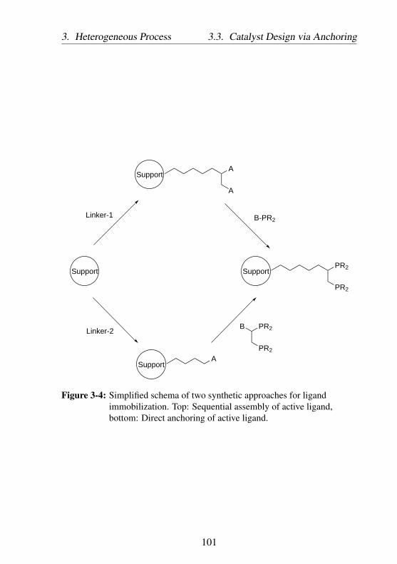
3. Heterogeneous Process 3.3. Catalyst Design via Anchoring
PR2
PR2
SupportSupport
ASupport
PR2
PR2
B
Linker-1
Support
Linker-2
A
A
B-PR2
Figure 3-4: Simplified schema of two synthetic approaches for ligandimmobilization. Top: Sequential assembly of active ligand,bottom: Direct anchoring of active ligand.
101

3.3. Catalyst Design via Anchoring 3. Heterogeneous Process
the ligand loading. On the other hand, the second strategy has the ad-vantage that the ligand can be well characterized before immobilization.An additional advantage of the second synthetic strategy is the fact, thatthe catalytic activity of the metal complexes in homogeneous catalyticreaction can be directly compared with their activity in heterogeneousone after immobilization. However, contrary to the first strategy, theligand can react with the reactive surface and not with the intendedfunctional group, resulting in inactive or non-accessible ligand. It istherefore essential to protect the catalytic active site of the ligand witha certain protecting group to avoid any unintended reaction betweensupport and the ligand.In general, there are two types of support which are frequently used forimmobilization purpose:
• Insoluble polymer supportsUse of polymer support was introduced by Merrifield in the solidphase peptide synthesis [223]. The synthesis method is frequentlyused in combinatorial chemistry, which has the highest impact inthe pharmaceutical industry and material science. The solid phasepeptide synthesis utilizes a cross-linked polystyrene resin withreactive functionality, for example Cl or Br. The insoluble, yet inorganic solvent swellable polymeric material is inert to commonsynthesis conditions during immobilization. Typically, it is pre-pared via radical suspension polymerization of styrene, function-alized styrene, and a cross-linker such as divinylbenzene. Poly-meric supports are however not suitable for reaction with hightemperature over 130 ○C or when highly electrophilic reagentsare used as it is no longer inert under those conditions.
102

3. Heterogeneous Process 3.3. Catalyst Design via Anchoring
• Oxide supportsOxides are cheap and abundantly available support materials. Ox-ides are one of the most frequently used types of supports in solidcatalysis. Contrary to polymer supports, oxides are chemicallyand thermally more stable in organic solvents. Moreover, theydisplay better thermal conductivity than polymer supports, so thatlocal hot-spot effects during reaction can be avoided.
The anchoring of the ligand is accomplished via the functionality ofthe solid support. The choose of suitable support is therefore crucial toensure facile substitution and high loading of the linker and/or ligand.In general, there are two different approaches, how the support can befunctionalized with a meaningful linker:
• Simultaneous support synthesis and functionalization.
• Post-synthetic functionalization.
In the first approach, the linker with appropriate reactive moiety is addedas the support synthesis takes place, whereas in the latter case the linkeris added in a second step after the synthesis of the support is completed.The first approach can be achieved, for example via co-condensation[224–227] of various organosilanes in case of organosilica support orcopolymerization of monomers with a certain functional group. Thisone-pot synthesis affords a material with homogeneous distribution ofthe linker. It also provides better control over the amount or loading ofthe linker in the support materials. This synthetic approach, however,is limited in that the linker, with their specific molecular sizes, hy-drophobic/hydrophilic properties, and concentrations, may compromisethe meso- or micro-structure of the resulting material [228]. Additionaldrawback is that a part of linker is sterically inaccessible for the reaction.The second synthetic approach can be accomplished, for example by
103
3.3. Catalyst Design via Anchoring 3. Heterogeneous Process
grafting a silica material with organosilanes [224, 227]. Post-syntheticmodification of a support is advantageous in that the pore size is betterdefined and the exterior surface of support material can be selectivelyfunctionalized. The fraction of accessible linker is therefore muchhigher in material prepared with the second approach. The disadvantageof this method is, however, that the linker tend to be anchored in theopening of the pore, blocking the internal catalyst pore. In addition, dueto mass transport phenomenon (film and pore diffusion), the reaction ofa linker with the surface is limited, thus repeated grafting with longerreaction time is necessary to achieve high loading.The immobilization effort discussed in this work will be based on twodifferent support classes: commercial polymer support with linker func-tionality prepared via copolymerization of the respective monomer (Si-multaneous support synthesis and functionalization) and silica materi-als, which was firstly grafted with organosilanes linker before furtherfunctionalization. The latter support material was prepared via post-synthetic modification via condensation of the organosilanes with thehydroxyl groups at the surface of the silica. The resulting Si-O-Sibond is strong such that it requires extreme conditions and strong acidsor bases to detach the grafted linker [229]. Grafting is significantlyaffected by several factors: solvent used for the reaction [230–232],temperature [233–236], type of organosilanes precursor [233], reactionduration [234,236,237], and post-treatment [231,237–241]. In addition,silanization carried out in solution also greatly depends on the concen-tration of organosilane [233, 242, 243] precursor and the presence oftrace water [237,242–244]. Generally, solvent with the presence of tracewater is desirable to prepare a smooth grafted silane layer. However,excess water results in uncontrolled polymerization of the silane bothon the surface of the support material as well as in solution, leading
104

3. Heterogeneous Process 3.3. Catalyst Design via Anchoring
to structural irregularities. Moreover, high silane concentration mayaccelerate the formation of oligomers and polymers in solution, whichwill reduce the amount of strongly grafted linker on the support material.It is also known that low reaction temperature promotes weakly bondedsilane linker, which is readily displaced upon washing with toluene,ethanol, or water. Post-treatment drying ensures that covalent bondformation proceeds through condensation of hydrogen bonded silanolgroups, and can be carried out either under vacuum [236] or under inertgas stream [245]. Among the organosilanes, ethoxysilanes are the mostpopular ones, yielding a well-defined functionalized surface withoutharmful acidic reaction byproducts and undesirable cross-linking [246].While Chlorosilanes are more reactive than alkoxysilanes, the resultingHCl during the reaction with silanol surface groups may affect the sta-bility of the anchored linker. Generally, grafting of organosilanes to thesilica surface can be carried out in two ways:
• under anhydrous condition (Figure 3-5).Organosilane react with the silanol groups of the silica directly,resulting in grafted silane molecules. Anhydrous grafting wasreported to afford equal and stable, monolayer functionalized sur-face [244, 247].
RO Si OROR
X
RO Si ORO
X
RO Si
X
OH
SiO2
O
OH OHOH OH
SiO2
OR
OH
Figure 3-5: Functionalization of silica surface with silanes in anhydrousconditions [248].
105

3.3. Catalyst Design via Anchoring 3. Heterogeneous Process
• in acid-aqueous solution (Figure 3-6).Organosilane is firstly hydrolyzed through the presence of wa-ter. The organosilanes with three hydroxyl groups can eitherreact with the silanol groups of the silica leading to grafting ofthe silane molecules or first react with each other leading to theformation of oligomers with subsequent grafting.
Further reaction of the linker on the catalyst surface to afford an ac-tive immobilized ligand can be achieved via several classical reactions,for example: nucleophilic substitution, metathesis, or click chemistrybased on the azide-alkyne Huisgen cycloaddition. Depending on thecomplexity of the metal complex or ligand, the synthetic effort can bechallenging and significantly determines the quality of the immobilizedcatalyst. In this work anchoring will be carried out via nucleophilicsubstitution. A support with reactive leaving group moiety is crucialfor successful ligand anchoring. A list of possible leaving groups X fornucleophilic substitution is listed in Table 3.1.
Table 3.1: Leaving groups ordered approximately in decreasing ability toleave [249]
Substrate RX Leaving groupR−N+
2 dinitrogen
R−OR’+2 dialkyl ether
R−OSO2RF perfluoroalkylsulfonates (e.g. triflate)
R−OTs, R−OMs, etc. tosylates, mesylates, and similar
R−I iodide
R−Br bromide
R−OH+2 water, conjugate acid of alcohol
R−Cl chloride, acyl halides
R−ORH+ conjugate acid of ether
106

3. Heterogeneous Process 3.3. Catalyst Design via Anchoring
R−ONO2, R−OPO(OH)2,R−OB(OH)2
nitrate, phosphate, and other inorganicesters
R−SR’+2 thiolate
R−NR’+3 amines
R−F fluoride
R−OCOR carboxylate, anhydrides
R−NH3 ammonia
R−OAr phenoxides, aryl esters
R−OH, R−OR hydroxide, alkoxides
R−H
R−NR2 amides
R−Ar aryl
R−R alkyl
The greater the ability of the leaving groups to leave, the higher theprobability of successful immobilization. However, the preparation ofthe support with very reactive leaving groups is challenging. In caseof Br functionalized supports, the balance between efforts necessary forsupport preparation and the reactivity during immobilization purpose isoptimal.Before the ligand is anchored, it is sometimes necessary to protect otherreactive nucleophilic moiety of the immobilized molecule before an-choring. This is especially relevant for strongly nucleophilic phosphineligand. One elegant way to overcome this problem is to protect thenucleophilic phosphorous with BH3. This approach has been used tosynthesize various complex phosphine ligands, leading to significantprogress in organophosphorous chemistry [250–253]. P-borane com-plexes can be prepared by reacting trivalent phosphorous compoundswith BH3-THF in ether as solvent or with BH3-SMe2 in benzene or
107

3.3. Catalyst Design via Anchoring 3. Heterogeneous Process
RO Si OROR
X
H2O
HydrolysisHO Si OH
OH
X
HO Si OHOH
X
HO Si OOH
X
Si OHOH
X
OH OHOH OH
SiO2
HO Si OHO
X
HO Si OO
X
Si OHO
X
O OOH O
SiO2
HH H H H H
HO Si OHO
X
HO Si O
X
Si OH
X
OH
SiO2
O O
-H2O
Dehydrationcondensation
O Si OO
X
O Si O
X
Si O
X
O
SiO2
O O
TMSCl
TMS
TMSTMS
TMSTMS
∆T
Figure 3-6: Functionalization of silica surface with silanes under aqueousconditions [248].
108
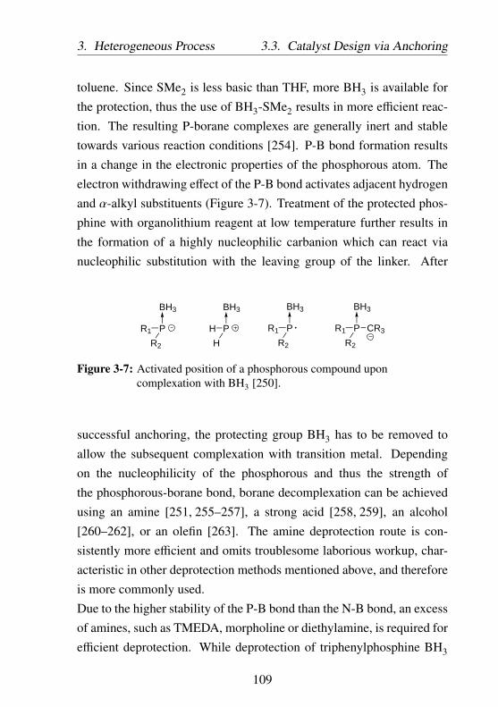
3. Heterogeneous Process 3.3. Catalyst Design via Anchoring
toluene. Since SMe2 is less basic than THF, more BH3 is available forthe protection, thus the use of BH3-SMe2 results in more efficient reac-tion. The resulting P-borane complexes are generally inert and stabletowards various reaction conditions [254]. P-B bond formation resultsin a change in the electronic properties of the phosphorous atom. Theelectron withdrawing effect of the P-B bond activates adjacent hydrogenand α-alkyl substituents (Figure 3-7). Treatment of the protected phos-phine with organolithium reagent at low temperature further results inthe formation of a highly nucleophilic carbanion which can react vianucleophilic substitution with the leaving group of the linker. After
P
BH3
R1
R2
P
BH3
H
H
P
BH3
R1
R2
P
BH3
R1
R2
CR3
Figure 3-7: Activated position of a phosphorous compound uponcomplexation with BH3 [250].
successful anchoring, the protecting group BH3 has to be removed toallow the subsequent complexation with transition metal. Dependingon the nucleophilicity of the phosphorous and thus the strength ofthe phosphorous-borane bond, borane decomplexation can be achievedusing an amine [251, 255–257], a strong acid [258, 259], an alcohol[260–262], or an olefin [263]. The amine deprotection route is con-sistently more efficient and omits troublesome laborious workup, char-acteristic in other deprotection methods mentioned above, and thereforeis more commonly used.Due to the higher stability of the P-B bond than the N-B bond, an excessof amines, such as TMEDA, morpholine or diethylamine, is required forefficient deprotection. While deprotection of triphenylphosphine BH3
109

3.3. Catalyst Design via Anchoring 3. Heterogeneous Process
complex into free phosphine can be reached in reaction with diethy-lamine for a few hours at 50 ○C, the liberation of BH3 from very basicphosphines may require more extreme conditions [257].In this work, the strategy to immobilize bidentate dcpe ligand will be fo-cused on anchoring at the bridge or on the cyclohexyl substituents of theligand to minimize modification of the electronic and steric propertiesof the ligand. The dcpe ligand can be deprotonated with organolithiumreagent, for example with tert-BuLi, generating the corresponding car-banion of the ligand. The carbanion reacts with brominated supportmaterial, resulting in a carbon-carbon bond formation, thus covalentlyanchoring the ligand (Figure 3-8).
PCy2
PCy2H
HLi-tBu
PCy2
PCy2H
SupportBr
SupportPCy2
PCy2
Figure 3-8: Simplified anchoring mechanism via SN2 reaction between alinker-functionalized support and a ligand.
3.3.1 Route 1: In situ sequential assembly of active ligand
Anchored dcpe was prepared by firstly grafting a silica support withan appropriate linker followed with the generation of chelate phosphinefunctionality. The silica support used in this route is specified in Table3.2. A linker with halogen functionality was prepared, so that its sub-sequent reaction with nucleophilic phosphine carbanion on the supportsurface may afford a dcpe ligand. Efficient synthesis and purificationof each product at each step is the key factor to obtain highly uniformimmobilized ligand. In this work, 1-allyloxy-2,3-epoxypropane waschosen as the linker backbone. Both the presence of oxygen atom and
110

3. Heterogeneous Process 3.3. Catalyst Design via Anchoring
Table 3.2: Silica support used for functionalization via Route 1: In situsequential assembly of active ligand.
Properties Cariact Q-20C
Average pore diameter [nm] 20
Specific surface area [m2/g] 140
Pore volume [mL/g] 0.8
O ClCl
OO
ClPPh2/NCS
O Si HO
O
O SiO
OO Cl
Cl
H2PtCl6/PTA
Figure 3-9: Preparation of 4-oxa-6,7-dichloro-1-heptyltrimethoxysilanelinker.
the length of the linker ensure high flexibility and sufficient distancebetween metal complex and the support. 1-allyloxy-2,3-epoxypropanewas first transformed into 4-oxa-6,7-dichloro-1-heptene with two re-active Cl moieties using chlorodiphenylphosphine (ClPPh2) to regios-electively open the epoxide ring and N-chlorosuccinimide (NCS) as theelectrophilic chlorine source [264, 265]. The product was then hydrosi-lylated to 4-oxa-6,7-dichloro-1-heptyltrimethoxysilane in the presenceof H2PtCl6 catalyst and 1,3,5-triaza-7-phosphaadamantane (PTA) ligand
111

3.3. Catalyst Design via Anchoring 3. Heterogeneous Process
at 80 ○C for 16 hours (Figure 3-9). The hydrosilylation conditions wereoptimized during preliminary experiments (Table 3.3).Hydrosilylation preliminary experiments were carried out with twoof the most popular industrial catalysts, the Speier’s catalyst H2PtCl6and Karstedt’s (alkene-stabilized platinum(0): Platinum(0)-1,3-divinyl-1,1,3,3-tetramethyldisiloxane complex) catalyst. The hydrosilylation ofthe 4-oxa-6,7-dichloro-1-heptene is favored at temperature of 80 ○C(Entry 6: yield = 45 %, Entry 7: yield = 54 %). H2PtCl6 catalyst displayhigher activity than the Karstedt’s catalyst. In reactions without solvent,Karstedt’s catalyst and H2PtCl6 provided product yield of 25 % (Entry3) and 54 % (Entry 7) yield respectively. In reactions with deuteratedtoluene as solvent (Entry 4 and Entry 10 as well 11), Karstedt’s catalystafforded product in 15 % yield while H2PtCl6 yielded 85 - 92 % prod-uct. Although the application of isopropanol as solvent resulted in highconversion of the starting material (over 90 %), 4-oxa-6,7-dichloro-1-heptyltriisopropoxysilane was obtained as byproduct, presumably due totransesterification of the intended product with the solvent, isopropanol.H2PtCl6 catalyzed hydrosilylation can be improved with the addition of1,3,5-triaza-7-phosphaadamantane (PTA) ligand to increase the stabilityand the solubility of the catalyst. This results in product formation with62 % yield. Contrary to previous experiments with Karstedt’s catalystor previous H2PtCl6 catalyst, the reaction with H2PtCl6 and PTA ligandafforded 4-oxa-6,7-dichloro-1-heptyltrimethoxysilane with high selec-tivity (82 %).In summary, hydrosilylation is a versatile tool to prepare a organosiliconcompounds. The reaction mechanism and product distribution of the hy-drosilylation reaction depend on the metal and the electronic and stericproperties of the ligands. The hydrosilylation reaction by late transition
112

3. Heterogeneous Process 3.3. Catalyst Design via Anchoring
metal complexes involves an oxidative addition of silanes and coordina-tion of alkene to a metal complex, followed by the subsequent migratoryinsertion of alkene into the M-H bond. Finally the resulting metal silylalkyl complex undergoes reductive elimination, releasing an organosi-lane product with Si-C bond (Figure 3-10). Possible side reactions dur-
Pt
PtH
SiR3
PtH
SiR3
R'R'
HSiR3
PtH
R'
R'
R3Si
Figure 3-10: Chalk-Harrod mechanism for hydrosilylation of olefins by latetransition metal complexes [266].
ing hydrosilylation may include isomerization, oligomerization, poly-merization and hydrogenation of alkenes as well as redistribution anddehydrogenation of silicon hydrides. Moreover, the transition metal canalso coordinate and form complex with the olefin or trimethoxysilanereactants, rendering the catalyst inactive. A coordinating ligand suchas PTA would not only increase the stability of the catalyst but alsoimprove the selectivity of the reaction [267].
113

3.3.C
atalystDesign
viaA
nchoring3.
Heterogeneous
Process
Table 3.3: Hydrosilylation of 4-oxa-6,7-dichloro-1-heptene with 1.1 eq. trimethoxysilane to give4-oxa-6,7-dichloro-1-heptyltrimethoxysilane. The conversion values are calculated from the ratio ofhydrosilylated product to educt with double bond 1H NMR spectra.⋆byproduct: 4-oxa-6,7-dichloro-1-heptyltriisopropoxysilane.Note that all reactions are carried out in a small vial with minimum amount of substances, thus inhomogenityis to be expected, which is caused primarily due to improper stirring.
Entry Catalyst Solvent T [°C] t [h] Yield [%] Remarks1 1 mol % Karstedt’s catalyst no solvent 40 4 0
2 1 mol % Karstedt’s catalyst THF 40 1 0
3 5 mol % Karstedt’s catalyst no solvent 80 20 25 inhomogenity
4 5 mol % Karstedt’s catalyst toluene-d8 80 20 15 several products
5 5 mol % H2PtCl6 no solvent 60 4 40 inhomogenity
6 5 mol % H2PtCl6 no solvent 60 20 45 inhomogenity
7 5 mol % H2PtCl6 no solvent 80 20 54 inhomogenity
8 5 mol % H2PtCl6 isopropanol 60 4 92⋆ ⋆byproduct
9 5 mol % H2PtCl6 isopropanol 60 20 93⋆ ⋆byproduct
10 5 mol % H2PtCl6 toluene-d8 80 20 85 two products
11 5 mol % H2PtCl6 toluene-d8 80 20 92 two products
12 5 mol % H2PtCl6 with 2eq. PTA ligand toluene-d8 80 20 43
114

3.H
eterogeneousProcess
3.3.C
atalystDesign
viaA
nchoring
13 5 mol % H2PtCl6 with 1.2eq. PTA ligand toluene-d8 80 20 62
115

3.3. Catalyst Design via Anchoring 3. Heterogeneous Process
The grafting of the prepared vic-chlorides silane linker was carried outin anhydrous conditions with toluene as solvent at reflux temperaturefor 48 hours. Methoxysilanes can be successfully grafted at the surfacewithout the need for any catalyst. To ensure complete silanes immobi-lization, trace amount of water was added to the reaction mixture andthe reaction mixture was further stirred at reflux temperature for 24hours. After washing and drying, the remaining hydroxyl groups ofthe silica was converted into silanes. Endcapping after silanization wasnecessary to eliminate all unreacted and accessible silanols on the silicasurface. Endcapping was carried out with excess chlorotrimethylsilane(Me3SiCl), starting at low temperature of about -40 ○C with slow warm-ing until reaching reflux temperature, at which the suspension is stirredfor 15 hours. After slow cooling to 25 ○C, the solid product was washedthree times with each 50 mL toluene, ether, and THF. Finally, the graftedsilica was dried in vacuum at 50 ○C for 18 hours.Each surface modification was accompanied with proper washing toprevent unintended side products in the following reaction. In ad-dition, the drying temperature has to be carefully chosen to avoidthe decomposition of the organic linker on the catalyst surface. Theconcentration of the vic-chlorides silane linker (4-oxa-6,7-dichloro-1-heptyltrimethoxysilane) on the surface was determined by elementalanalysis at 0.045 mmol/g (0.09 mmol/g Cl). The low concentrationof the grafting can be associated with limited collision probability ofthe silane in the liquid phase with the surface of the solid material.Multiple-steps grafting may be necessary to improve the loading of thelinker on the catalyst support. After the silica support was successfullyfunctionalized with 4-oxa-6,7-dichloro-1-heptene linker, LiPCy2 wasadded to allow nucleophilic substitution with the chlorine moieties ofthe linker. Complete substitution generates anchored dcpe ligand. After
116

3. Heterogeneous Process 3.3. Catalyst Design via Anchoring
P
P
LiPCy2
Support
Support
Support
P
PNi
OO
Support
Nickelalactoneformation
O SiO
OO Cl
Cl
O SiO
OO Cl
Cl
OH
Figure 3-11: Assembling the building blocks of1,2-bis(dicyclohexylphosphino)-ethane (dcpe) on support.
thorough washing and vacuum drying, the catalyst was subjected to lig-and exchange reaction with (tmeda)-Nickelalactone, yielding anchored(dcpe)-nickelalactone. The concentration of phosphorous on the cata-lyst surface was determined with elemental analysis (0.056 mmol/g).However, the low concentration of the phosphorous on the catalystsurface prevents a thorough characterization by MAS-NMR. Therefore,the immobilized nickel complex catalyst prepared with this route wasdirectly tested for its activity without previously confirming the presenceof nickel complex on the surface of the material.The catalyst was subjected to ligand exchange with (tmeda)-nickelalactoneto give an immobilized (dcpe)-nickelalactone catalyst. The methodalready applied in Subchapter 2.2 was utilized for this purpose. The
117
3.3. Catalyst Design via Anchoring 3. Heterogeneous Process
immobilized catalyst and 2 eq. of (tmeda)-nickelalactone were sus-pended in THF and stirred at 25 ○C for 18 hours. The reaction mix-ture is then filtrated, washed with N,N-dimethylformamide and THFto completely remove unreacted (tmeda)-nickelalactone, and dried invacuum. Catalytic reaction was carried out in one pot process with10 eq. triethylamine and 10 eq. NaH base system in the presence of10 bar ethylene and 20 bar CO2 at 100 ○C for 72 hours with THF asreaction solvent. The sodium acrylate was extracted from the reactionmixture with D2O and measured with 1H NMR. The reaction yieldedno detectable sodium acrylate product. This, however, is not a solidproof that the catalytic reaction with immobilized nickel complex didnot work. The concentration of sodium acrylate generated from thecatalytic reaction may be well below the detection limit of NMR. Fur-ther experiments with immobilized catalyst prepared with this route arenecessary to confirm this hypothesis.
3.3.2 Route 2: Direct anchoring of active ligand
Alternatively, an active ligand can also be directly anchored onto supportmaterials. For this purpose, a suitable support with appropriate reactivemoiety to facilitate anchoring has to be prepared.
Support Materials
In this work, silica modified with 3-bromopropyltrimethoxysilane andcommercially available halogenated crosslinked polystyrene were usedas supports for ligand anchoring. The commercially available polystyrenesupport is typically prepared via copolymerization of the styrene monomer,divinylbenzene as crosslinker, and styrene with desired functionality[268,269]. Several polystyrene supports used in this work are illustratedin Figure 3-12. The brominated silica supports were prepared via con-
118

3. Heterogeneous Process 3.3. Catalyst Design via Anchoring
PSBr
SiO2 O SiO
OBr
OTMS
OTMS
PSO
Cl
PSO
Br
PSCl
PS01
PS02
PS03
PS04
S1: Br loading = 0.5632 mmol/gS2: Br loading = 1.1889 mmol/gBrSBA-15: Br loading = 0.6007 mmol/g
Cl loading = 6.05 mmol/g
Cl loading = 1.27 mmol/g Br loading = 0.91 mmol/g
Br loading = 0.9 mmol/g
Figure 3-12: Supports used for dcpe immobilization via direct anchoringroute. Loading of Cl and Br moiety was determined byelemental analysis department of BASF.
densation of 3-bromopropyltrimethoxysilane with the surface hydroxylgroups of Cariact Q-20C and SBA-15 (hydroxyl content: 2.8 mmol/gvia quantitative 1H MAS NMR, see also product specification in Table3.4) [270] silica materials.The grafting was carried out in the presence of a trace of water (0.3mL water for each gram support) and HCl as catalyst at toluene refluxtemperature.High Br loading of the functionalized supports depends on the concen-tration of the surface hydroxyl group of the silica and the amount of3-bromopropyltrimethoxysilane precursor added during the functional-ization.
119

3.3. Catalyst Design via Anchoring 3. Heterogeneous Process
Table 3.4: Silica supports used for functionalization.
Properties Cariact Q-20C SBA-15 [270]
Average pore diameter [nm] 20 6
Specific surface area [m2/g] 140 1164
Pore volume [mL/g] 0.8 1.25
-OH content [mmol/g] no data 2.8
Supplier Fuji Silysia University of
Chemical Stuttgart
During grafting targeting the surface hydroxyl groups, the silane linkerprecursor may also react with each other. This would reduce the amountof the silane linker available for surface functionalization. From theamount of Br detected in the grafted silica, side reaction during func-tionalization was estimated to be about four times faster. Only about 20% of starting material (3-bromopropyltrimethoxysilane) used could bedetected in the modified silica after grafting (Table 3.5). Thus, multiple-steps functionalization reactions were carried out to increase the Brloading.As comparison, two-steps functionalization yielded Br silica productwith Br concentration as high as 1.1889 mmol/g (Entry 2: yield grafting20.81 %) while one-step functionalization only yielded product with Brconcentration of 0.5632 mmol/g (Entry 1: yield grafting 19.71 %). Thepercentage of starting material grafted at the support material, however,remains constant at around 20 %. This means that the grafting of thesilane linker is strongly limited by the contact probability between thelinker in the liquid phase and the silanol groups on the surface of thecatalyst. After successful immobilization of the linker, the silica productwas treated with excess chlorotrimethylsilane to eliminate all unreacted
120

3. Heterogeneous Process 3.3. Catalyst Design via Anchoring
and accessible silanols on the surface of the support material. Endcap-ping was carried out with excess chlorotrimethylsilane, starting at lowtemperature of about -40 ○C with slow warming until reaching refluxtemperature, at which the suspension is stirred for further 15 hours. Thereaction mixture was slowly cooled down to 25 ○C and the solid prod-uct was washed three times with toluene, ether, and THF. Finally, thegrafted silica was dried in vacuum at 50 ○C for 18 hours to remove tracesof solvents. Each surface modification was accompanied with thoroughwashing to prevent unintended side products in the following reaction.In addition, the drying temperature has to be carefully considered toprevent the decomposition of the organic linker on the catalyst surface.
121

3.3.C
atalystDesign
viaA
nchoring3.
Heterogeneous
Process2
Table 3.5: Grafting of silica support with 3-bromopropyltrimethoxysilane (BrSi). Synthetic details can be found inAppendix A.3.2.
Sample nameSupport
BrSi educt Br loading Yield GraftingRemarks
name [mmol/g Support] [mmol/g] [%]S1 Cariact Q-20C 2.857 0.5632 19.71 one-step grafting
S2 Cariact Q-20C 2 x 2.857 1.1889 20.81 two-steps grafting
BrSBA-15 SBA-15 2.800 0.6007 21.45 one-step grafting
122

3. Heterogeneous Process 3.3. Catalyst Design via Anchoring
Ligand anchoring
The active ligand can be anchored onto support material by forminga covalent carbon-carbon bond via nucleophilic substitution of the nu-cleophilic carbanion ligand with the electrophilic linker on the surfaceof the support material. Before anchoring the ligand at the supportmaterial, it is necessary to ensure that the ligand does not display anyactive moiety which may disturb or react during the process. In case ofdcpe ligand, one has to take care about the nucleophilic phosphorous,which may prone to side reactions, for example: oxidation, lithiation, orreaction with other reactive functional groups of the support. To preventthese unintended side reactions, the dcpe ligand was treated with BH3-SMe2 in THF as solvent. The reaction was carried out at 25 ○C for24 hours. After THF removal in vacuum, the dcpe⋅2 BH3 complex wasrecrystallized from toluene. 31P NMR confirmed a successful protectionof the dcpe ligand, as indicated by a doublet at 28.37 ppm (solvent:CDCl3, 202.55 MHz 31P NMR, 1JPB = 64.4 Hz). Upon protection withBH3, the electron withdrawing effect of the P-B bond activates adjacentα-carbon atom. Treatment with organolithium reagent at 0 ○C for 2hours further increases the nucleophilicity of the α-carbon, resulting ina highly nucleophilic dcpe carbanion which can attack the electrophiliccarbon of the linker grafted on the catalyst support.Support material bearing Br moiety, strong nucleophilic dcpe carban-ion and polar aprotic solvent THF used during anchoring facilitate SN2type reaction. Successful anchoring of the ligand can be quantified byintroducing the following equaton:
Degree o f Anchoring =Amount o f dcpe anchored at support
Amount o f dcpe educt at start(3.1)
123

3.3. Catalyst Design via Anchoring 3. Heterogeneous Process
P
P BH3
BH3P
P 2BH3.DMS
P
P BH3
BH3
tBuLi Li
P
P BH3
BH3
X
P
PNi
O
Support
P
P
deprotection
O
Support
Support
Support
Nickelalactoneformation
Figure 3-13: Direct anchoring of 1,2-bis(dicyclohexylphosphino)-ethane(dcpe).
124

3. Heterogeneous Process 3.3. Catalyst Design via Anchoring
The success of an anchoring of dcpe depends on several factor such as(Table 3.6):
• Solvent, which assists the coordination of organolithium reagent,thus increasing its reactivity and affect the amount of dcpe carban-ion (Figure 3-14). It is important to keep the amount of solventto minimum during lithiation as the solvent reduce the half timeof the organolithium reagents. In this work, THF was chosen aslithiation solvent due to its relatively strong coordinating powerand the high solubility of dcpe ligand in this solvent.
• Trace water and other impurities during the reaction, which mayresult in side reactions with the dcpe carbanion.The pre-treatment of the support determines the final dcpe loadinggreatly. This could be affected by the presence of trace waterduring the reaction. Polystyrene support PS03, which is pre-driedin vacuum at 25 ○C overnight, yielded dcpe loading of 0.134mmol/g (Table 3.6 Entry 8, degree of anchoring 29.13 %), whilesupport, which is pre-dried in vacuum at 0 ○C overnight yieldeda constant dcpe loading of 0.065 mmol/g (degree of anchoring14.44 %), 0.0775 mmol/g (degree of anchoring 16.85 %), and0.0759 mmol/g (degree of anchoring 16.5 %). Support pre-driedat higher temperature should contain less trace water. This wouldprevent undesired hydrolysis of the dcpe carbanion. As a result,higher amount of dcpe carbanion would be available during the re-action, leading to a higher degree of anchoring. Support pre-driedat high temperature of 50 ○C (Table 3.6 Entry 4) also displayeda moderate dcpe loading, 0.063 mmol/g (degree of anchoring13.99 %). Although the anchoring conditions are not identical(-75 ○C for 6 hours followed with 0 ○C for 16 hours instead of
125

3.3. Catalyst Design via Anchoring 3. Heterogeneous Process
PO
Me2N NMe2NMe2 HMPA
Me2N
MeN
NMe2
N N
O
DMPU
OO 1,2-dimethoxyethane
Me2NNMe2
O
TMEDA
THF
O t-butyl methyl ether
O diethyl ether
PMDTA
incr
ease
d st
abili
ty o
f tB
uLi
decr
ease
d co
ordi
natin
g po
wer
half life of tBuLi at -20 °C: 8h
half life of tBuLi at -20 °C: 45min
Figure 3-14: Common solvents for lithiation [271].
0 ○C for 72 hours), this should serve as a proof that the primarybrominated linker is also stable at high temperature and resistantto elimination reaction.
• The amount of dcpe carbanion starting material which is addedinto the reaction.
126

3. Heterogeneous Process 3.3. Catalyst Design via Anchoring
The amount of dcpe starting material reflects the final dcpe load-ing of the support, until a certain concentration, where the in-crease in dcpe starting material is no longer proportional to thedcpe loading of the support. This is demonstrated in Table 3.6Entry 14 and 15. Reaction with dcpe starting material of 0.323mmol/mmol Br moiety at the support yielded a material with dcpeloading of 0.0743 mmol/g (degree of anchoring 19.39 %). Fourfold increase of the dcpe starting material to 1.2 mmol/mmol Brmoiety at the support yielded material with dcpe loading of only0.1566 mmol/g (degree of anchoring 11.08 %). After reachinga certain dcpe loading, the support becomes overcrowded andthe resulting steric prevents any further anchoring of dcpe at thesupport.
• Temperature and duration of the anchoring.The best result for direct ligand anchoring was performed at 0 ○Cfor 72 hours (Table 3.6 Entry 8 - 15). All anchoring reactionsconducted under these conditions delivered high dcpe loading onthe support with anchoring degree of over 10 %. Low temperatureinhibits the decomposition of dcpe carbanion while long reactionduration favors the slow anchoring reaction of the ligand at thesupport.
127

3.3.C
atalystDesign
viaA
nchoring3.
Heterogeneous
Process
Table 3.6: Direct anchoring of dcpe on the support material via nucleophilic substitution. Values of dcpe loading werederived from elemental analysis results. X = linker loading on the support material.Degree of anchoring = ratio of anchored dcpe to dcpe starting material.Conditions: ⋆A: 2h at -40 ○C, 72h at 25 ○C. ⋆B: 24h at 0 ○C. ⋆C: 72h at 0 ○C. ⋆D: 6h at -75 ○C, 16h at 0 ○C.⋆E: 6h at -75 ○C, 8h at 0 ○C. ⋆F: 6h at -75 ○C, 90h at 0 ○C. ⋆G: 72h at 0 ○C. Remarks: ⋆1: support pre-driedin vacuum at 50 ○C overnight. ⋆2: support pre-dried in vacuum at 25 ○C overnight, addition of 20 eq. LiHduring anchoring. ⋆3: support pre-dried in vacuum at 25 ○C overnight. ⋆4: support pre-dried in vacuum at 0○C overnight.
EntrySample
Support Conditionsdcpe:X ratio dcpe loading on Degree of
Remarksname [mmol/mmol] support [mmol/g] anchoring [%]
1 A5 PS01 ⋆A 2.00 0.0200 0.16 ⋆1
2 A6 PS02 ⋆B 1.95 0.0180 0.72 ⋆1
3 A7 PS04 ⋆C 0.50 0.0280 6.14 ⋆1
4 A8.1 PS03 ⋆D 0.50 0.0630 13.99 ⋆1
5 A8.2 PS03 ⋆E 0.50 0.0095 2.12 ⋆1
6 A8.3 PS03 ⋆E 0.50 0.0274 6.10 ⋆2
7 A8.4 PS03 ⋆F 0.50 0.0194 4.31 ⋆2
8 A8.5 PS03 ⋆G 0.51 0.1340 29.13 ⋆3
9 A8.6 PS03 ⋆G 0.50 0.0650 14.44 ⋆4
10 A8.7 PS03 ⋆G 0.50 0.0775 16.85 ⋆4
128

3.H
eterogeneousProcess
3.3.C
atalystDesign
viaA
nchoring
11 A8.8 PS03 ⋆G 0.50 0.0759 16.50 ⋆4
12 A4 S1 ⋆G 0.68 0.0678 17.69 ⋆1
12 A9.1 BrSBA-15 ⋆G 1.48 0.1388 15.64 ⋆1
13 A9.2 BrSBA-15 ⋆G 1.48 0.1518 17.09 ⋆1
14 A10.1 S2 ⋆G 0.32 0.0743 19.39 ⋆1
15 A10.2 S2 ⋆G 1.20 0.1566 11.08 ⋆1
129

3.3. Catalyst Design via Anchoring 3. Heterogeneous Process
The dcpe direct anchoring approach is readily reproducible. Anchoringon BrSBA-15 with the exact synthetic conditions yielded degree of an-choring of 15.64 % and 17.09 % (Entry 12 and 13). Another exampleare the immobilizations on PS03 support (Entry 9-11) with a degree ofanchoring of each 14.44 %, 16.85 %, and 16.5 %.The fraction of dcpe anchored on support materials may reach up to 29% of the total dcpe starting material. This undermines the difficulty ofsurface solid-fluid reaction involving nucleophilic substitution. Higheravailability of Br functional group did not result in an increased degreeof anchoring. For example in Entry 12, S1 support with Br loading of0.5632 mmol/g, which after treated with 0.68 eq. dcpe anion resultsin a catalyst with dcpe loading of 0.0678 mmol/g (degree of anchoring17.69 %), while in Entry 15: S2 support with Br loading of 1.1889mmol/g only yielded a catalyst with dcpe loading of 0.1566 mmol/g(degree of anchoring 11.08 %) after treated with 1.2 eq. dcpe anion.In addition, the dcpe loading on the support materials depends greatlyon the physical properties of the support itself: the surface area, thepore size (see also Table 3.4), and the linker loading (see also Table3.5 and Figure 3-12) of the support material. After reaching a certaindcpe loading, the support becomes overcrowded and the resulting stericbarrier prevents any further anchoring of dcpe on the support.Successful immobilization of dcpe⋅2 BH3 on the silica surface was con-firmed with 31P MAS NMR (Figure 3-15) with characteristic chemicalshift at around 24 ppm (as comparison: 202.55 MHz 31P NMR δ = 28.37ppm, solvent NMR: CDCl3). The P-B coupling observed in solventNMR at 64.4 Hz can hardly be distinguished in solid state NMR. Thedifference in chemical shift between solvent NMR and solid state NMRis solely due to the solvent effect. Similar 31P MAS NMR pattern was
130

3. Heterogeneous Process 3.3. Catalyst Design via Anchoring
Figure 3-15: 31P MAS NMR for immobilized dcpe⋅2 BH3 on silica supportS1 (A4, see also Table 3.6).
also observed for signals corresponding to the phosphorous atom of thedcpe⋅2 BH3 immobilized at polystyrene surface (Figure 3-16).
Figure 3-16: 31P MAS NMR for immobilized dcpe⋅2 BH3 on polystyrenesupport PS03 (A8.8, see also Table 3.6).
131

3.3. Catalyst Design via Anchoring 3. Heterogeneous Process
Activation: Deprotection of BH3
After adequate filtration and washing to remove non-immobilized lig-and, the catalyst was dried and subjected to treatment with nucleophilicamine base, such as dabco or morpholine, to deprotect the borane moi-ety. However, deprotection of BH3 from the nucleophilic dcpe is nottrivial. In preliminary deprotection experiments with non-immobilizeddcpe (Table 3.7), several deprotection approaches were investigated:with amine base (Entry 1 - 3, and 5), with an alcohol (Entry 4), andwith an acid (Entry 6). In deprotection experiments with excess diethy-lamine base, BH3 removal is best achieved at long reaction time. Whiledeprotection at 50 ○C for 8 hours resulted in a conversion of just 64.5% with dcpe selectivity of about 29 % (Entry 1), deprotection at 50○C after 48 hours resulted in a conversion of 70.6 %, with higher dcpeselectivity of 49.5% (Entry 2). Temperature increase to 100 ○C withshorter reaction time (24 hours), however, yielded less conversion ofabout 33 %, with dcpe selectivity of 34.2 % (Entry 3). Deprotection withmethanol seems to be unsuitable for biphosphine with alkyl substituents:deprotection with this approach converted only about 11 % dcpe⋅2 BH3,which transformed into an oxide of dcpe directly (Entry 4). On theother hand, deprotection with dabco (Entry 6) at 100 ○C afforded a highconversion of 86.4 %, 32.2 % of which gave an active dcpe product.While deprotection with acidic HBF4 (Entry 7) successfully converted100 % of all dcpe⋅2 BH3 with 94.8 % selectivity in dcpe, the subsequentwork up associated with this approach is not well suited for immobilizedligand catalyst. The presence of acid may promote the decompositionof the linker connecting the active ligand with the support. Deprotectionwith morpholin at harsh condition, 110 ○C for 3 hours, converted 89 %of all dcpe⋅2 BH3 with 78.4 % selectivity in dcpe.
132

3.H
eterogeneousProcess
3.3.C
atalystDesign
viaA
nchoring
Table 3.7: Deprotection of non-immobilized dcpe⋅2 BH3. NMR Selectivity and conversion were determined from theintegral of each compound in 31P NMR spectra.
EntryDeprotection
SolventT t NMR Selectivity NMR Conversion
agent [○C] [h] dcpe [%] dcpe⋅2 BH3 [%]1 200 eq. diethylamine - 50 8 28.99 64.5
2 200 eq. diethylamine - 50 48 49.5 70.6
3 200 eq. diethylamine - 100 24 34.2 33
4 molsieve - methanol dioxane 115 100 0 11
5 12.5 eq. dabco THF 100 96 32.2 86.4
6 20 eq. HBF4 DCM -10 12 94.8 100
7 1.5 eq. morpholin - 110 3 78.4 89
133

3.3. Catalyst Design via Anchoring 3. Heterogeneous Process
The activity of some deprotected dcpe was tested in one-pot catalyticreaction with P1-NaH base system to validate the activity of the molec-ular catalyst after deprotection (Table 3.8). All deprotected ligandsdisplayed catalytic activity similar to benchmark reaction with freshdcpe. Both ligands deprotected with diethylamine (Entry 2) or dabco(Entry 3) yielded a normalized TON (hypothetical TON if 100 % ligandis active for the reaction) of 2.93 and 3.04 respectively for 72 hoursreaction time. On the other hand, a catalytic reaction with dcpe ligandtreated with HBF4 yielded a TON of 0.62 for 18 hours reaction time.This may be caused by the presence of trace amount of acid, which canreact with the base, reducing the amount of active base for the cleavageof the nickelalactone during the catalytic reaction. This phenomenonwas not observed in ligand deprotected with amine base. Deprotection
Table 3.8: Catalytic activity of deprotected dcpe. Parameters: 0.2 mmolNi(COD)2, 0.22 mmol ligand, Base: 2.5 mmol P1, 10 mmol NaH,5 bar ethylene, 10 bar CO2, 45 mL THF, T = 80 ○C. Values inparenthesis represent hypothetical TON for 0.2 mmol molecularcatalyst (100 % ligand is active).
Entry LigandFraction of
active ligandTON [-]
[%] t = 18h t = 72h
1 dcpe 100 1.41 3.28
2 Table 3.7Entry 2
49.5 - 1.45 (2.93)
3 Table 3.7Entry 5
32.2 - 0.98 (3.04)
4 Table 3.7Entry 6
94.8 0.62 (0.65) -
approaches with diethylamine and dabco were therefore directly applied
134

3. Heterogeneous Process 3.3. Catalyst Design via Anchoring
in immobilized catalysts. The immobilized catalyst was suspended ineither neat diethylamine or THF with dissolved dabco and reacted atthe same conditions as those in Table 3.7. However, 31P MAS NMRinvestigation of the catalysts did not confirm any successful deprotection(Figure 3-17). Deprotection with morpholin at harsh conditions (110 ○C
Figure 3-17: 31P MAS NMR for dcpe⋅2 BH3 immobilized on silica supportS1 (A4, see also Table 3.6) after treatment with 20 eq. dabcowith THF as solvent at 100 ○C for 24 hours.
for 3 hours) successfully removed BH3 from immobilized catalyst asmonitored with 31P MAS NMR (Figure 3-18 and Figure 3-19). Thechemical shift at -7.45 ppm (silica support, Figure 3-18) or -4.99 ppm(polystyrene support, Figure 3-19) correspond to an active immobilizeddcpe (as comparison, the corresponding non-immobilized dcpe ligandprovided δ = 2.1 ppm in the 31P NMR spectra with CDCl3 as solvent),while that at 51.33 ppm corresponds to a dcpe oxide, which is formedwhen a dcpe ligand is exposed to oxidant. After a successful deprotec-tion, the peak intensity at 23.75 ppm, which represents dcpe⋅2 BH3, de-creased significantly. The active catalyst can finally be used in catalyticreaction by introducing Ni(COD)2 or (tmeda)-Nickelalactone, resultingin immobilized dcpe-Ni complex or immobilized (dcpe)-Nickelalactone
135

3.3. Catalyst Design via Anchoring 3. Heterogeneous Process
Figure 3-18: 31P MAS NMR for dcpe immobilized on silica support S1 (A4,see also Table 3.6) after treatment with excess morpholin (10mL for 1 g catalyst) at 110 ○C for 3 hours.
Table 3.9: Reference data 31P NMR.
Entry Compounds δ solvent NMR[ppm]
δ MAS NMR[ppm]
1 dcpe 2.1 (CDCl3) -7.45
2 dcpe⋅2 BH3 28.7 (CDCl3) 24.53
3 dcpe oxide 50 (CDCl3) 51.3
4(dcpe)-
nickelalactone
61.98, 69.36(CD2Cl2); 66.66,72.89 (THF-d8)
expected 60 - 80
complex as a catalytic species in the catalytic reaction respectively. Inthis work, three different pre-treatments were carried out to achievethese catalytic species:
136

3. Heterogeneous Process 3.3. Catalyst Design via Anchoring
Figure 3-19: 31P MAS NMR for dcpe immobilized on polystyrene supportPS03 (A8.8, see also Table 3.6) after treatment with excessmorpholin (10 mL for 1 g catalyst) at 110 ○C for 3 hours.
• Pre-treatment A: introduction of Ni(COD)2 and activated immo-bilized dcpe into the reactor. The immobilized nickel complexwas formed in situ, which started the catalytic reaction in thepresence of ethylene, CO2, and amine-NaH base system.
• Pre-treatment B: in situ formation of immobilized (dcpe)-nickel-alactone via ligand exchange with (tmeda)-nickelalactone. Theligand exchange was carried out at 25 ○C for 3 hours, after whichother reactants were added and the catalytic reaction was started.
• Pre-treatment C: separate formation of immobilized (dcpe)-nickelalactone via ligand exchange with (tmeda)-nickelalactone
137

3.3. Catalyst Design via Anchoring 3. Heterogeneous Process
under inert conditions. The ligand exchange was carried out in ar-gon at 25 ○C for 18 hours. The catalyst was subsequently washedto remove any byproducts and introduced into the reactor alongwith other reactants.
In the latter approach, the catalyst was also characterized with 31PMAS NMR before catalytic reaction. The stability of immobilized(dcpe)-nickelalactone is however very limited and thus can hardly beconfirmed via offline MAS NMR. As comparison, non-immobilized(dcpe)-nickelalactone decomposes readily in the presence of oxidant at25 ○C or at temperature above 60 ○C in argon atmosphere to give dcpeoxide. In 31P MAS NMR of immobilized catalyst on silica, strong dcpeoxide signal can be observed at around 52.19 ppm. The characteristicsignal of free dcpe (at around -7 ppm) in catalyst after ligand exchangewith (tmeda)-nickelalactone (Figure 3-20 and Figure 3-21) is not aspronounced as the signal in catalyst before ligand exchange (Figure 3-18). This indicates that the immobilized dcpe reacted with (tmeda)-nickelalactone, forming immobilized (dcpe)-nickelalactone complex,which decomposed to give immobilized dcpe oxide during or before theoffline MAS NMR characterization took place. The chemical shift ofimmobilized (dcpe)-nickelalactone complex is expected at around 60 -80 ○C. The difference in chemical shift between solvent NMR and solidstate NMR is solely due to the solvent effect. It is also interesting toobserve a signal at 44 ppm in Figure 3-21, which may be related to dcpeinteraction with silanol surface moiety. The signals at around 100 ppmare the spinning sidebands and should not be viewed as relevant.
138

3. Heterogeneous Process 3.4. Catalytic Performance Results
Figure 3-20: 31P MAS NMR for immobilized dcpe anchored on SBA-15 afterligand exchange with (tmeda)-nickelalactone. Deprotectionconditions: excess morpholin at 110 ○C for 3 hours.
Figure 3-21: 31P MAS NMR for immobilized dcpe anchored on silica gelCariact Q-20C after ligand exchange with(tmeda)-nickelalactone. Deprotection conditions: excessmorpholin at 110 ○C for 3 hours.
3.4 Catalytic Performance Results
The prepared immobilized catalytic species was injected into autoclavevia a charger system along with solvent, base, and sodium hydride.Liquid base was used to allow one-pot process and to improve thecollision probability between the immobilized catalyst and the base.
139

3.4. Catalytic Performance Results 3. Heterogeneous Process
All immobilized ligands tested in this work are depicted in Figure 3-22. Preliminary experiments with immobilized monophosphine withphenyl substituents (catalyst A1, A2, and A3) did not yield any catalyticactivity. These results are in accordance to the preliminary experimentsthat most phosphines are inactive in the catalytic formation of sodiumacrylate. Immobilized catalysts A4, A5, A6, A7, and A8.1 - A8.3 wereprepared rather for proof-of-concept purposes and were not tested incatalytic reaction due to their low dcpe loading.
140

3. Heterogeneous Process 3.4. Catalytic Performance Results
SiO2
P
PS P
PS
P
loading = 0.7 mmol/g
loading = 3.2 mmol/g
loading = 2.5 mmol/g
A1
A2
A3
SiOO
O
S1
O
TMS
OTMS
P
P
Cy Cy
CyCyA4
loading = 0.0678 mmol/g
PSPCy2
PCy2
A5
loading = 0.02 mmol/g
PSA6
loading = 0.018 mmol/g
OPCy2
PCy2
PSA7
loading = 0.028 mmol/g
OPCy2
PCy2
PSA8 PCy2
PCy2
A8.1: loading = 0.063 mmol/gA8.2: loading = 0.0095 mmol/gA8.3: loading = 0.0274 mmol/gA8.4: loading = 0.0194 mmol/gA8.5: loading = 0.1340 mmol/gA8.6: loading = 0.065 mmol/gA8.7: loading = 0.0775 mmol/gA8.8: loading = 0.0759 mmol/g
SiOO
O
SBA-15
O
TMS
OTMS
P
P
Cy Cy
CyCyA9
A9.1: loading = 0.1388 mmol/gA9.2: loading = 0.1518 mmol/g
SiOO
O
S2
O
TMS
OTMS
P
P
Cy Cy
CyCyA10
A10.1: loading = 0.0743 mmol/gA10.2: loading = 0.1566 mmol/g
SiOO
OO PCy2
PCy2
SiO2
O
TMS
OTMS
A11
loading = 0.028 mmol/g
Figure 3-22: Overview of immobilized ligand investigated.141

3.4.C
atalyticPerform
anceR
esults3.
Heterogeneous
Process
Table 3.10: Activity of immobilized ligand in the catalytic acrylate reaction. Solvent: 45 mL THF. Temperature = 100○C, Cation source: NaH, Base: Triethylamine (NEt3) or N,N-dimethylaniline (DMA). Assumption: allimmobilized ligands are successfully complexated with Nickel and are active. TON is refered to the amountof immobilized ligand measured via elemental analysis.
Entry CatalystPre- ncatalyst Base
nbase ncation t pC2H4pCO2
TON [-]treatment [mmol] [mmol] [mmol] [h] [bar] [bar]
1 A8.4 A 0.0291 NEt3 10 5 72 5 10 0.9622
2 A8.5 A 0.0938 NEt3 5 10 72 5 10 0
3 A8.6 A 0.0130 NEt3 5 5 72 5 10 0
4 A9.1 C 0.1388 NEt3 10 5 48 5 10 0
5 A11 A 0.0297 NEt3 10 5 48 5 10 0
6 A10.1 C 0.0371 NEt3 10 5 92 5 10 0
7 A8.7 B 0.0886 NEt3 10 5 92 5 10 0.6769
8 A8.8 C 0.0380 NEt3 10 5 72 10 20 1.4198
9 A10.2 C 0.0371 DMA 5 5 72 10 20 0
10 A9.2 C 0.0371 DMA 5 5 72 10 20 0
11A8.8
C 0.0380 NEt3 10 5 72 10 20 0after 1 week
142

3. Heterogeneous Process 3.4. Catalytic Performance Results
In general, catalytic activity was only observed for catalysts preparedfrom ligands immobilized on polystyrene support (A8 class catalysts).For this immobilized ligand class, three different pre-treatments werecarried out to prepare the relevant catalytic species. In Table 3.10 Entry1 - 3 (Pre-treatment A), the catalyst was introduced as activated im-mobilized dcpe ligand along with Ni(COD)2, triethylamine-NaH basesystem, and ethylene and CO2. Catalyst A8.4 (Entry 1) displayed asub-catalytic activity with TON of 0.9622, while the other catalyst A8.5(Entry 2) and A8.6 (Entry 3) did not yield any sodium acrylate prod-uct. In case of catalyst A8.4 (Entry 1), two times as much triethy-lamine base was used, in order to increase the probability of immobi-lized nickel catalyst to come in contact with base, thus facilitating thecleavage of nickelalactone intermediate present at the catalyst surface.The exact reaction conditions were repeated with catalyst A8.7 (Table3.10 Entry 7), which delivered sodium acrylate with TON of 0.6769.The catalytic species in Table 3.10 Entry 7 was prepared with pre-treatment B, where the activated immobilized dcpe was brought intocontact with (tmeda)-nickelalactone in the autoclave at 25 ○C. After 3hours, other reactants were added and the catalytic reaction was started.Although catalyst A8.7 has higher dcpe loading, the in situ ligandexchange with (tmeda)-nickelalactone was estimated to deliver loweramount of active catalytic species. Table 3.10 Entry 7 highlights thepossibility of convenient one-pot catalytic reaction where the unstable(dcpe)-nickelalactone species was prepared in situ just before reaction.The presence of (tmeda)-nickelalactone should not interfere with thecatalytic reaction itself. The blank reaction with (tmeda)-nickelalactoneand the combination of triethylamine-NaH base did not provide sodium
143

3.4. Catalytic Performance Results 3. Heterogeneous Process
acrylate, which eliminates the possibility of (tmeda)-nickelalactone in-fluencing the TON value. The catalytic reaction in Table 3.10 En-try 7 worked by firstly forming an immobilized (dcpe)-nickelalactonespecies, which was cleaved by triethylamine-NaH base to give sodiumacrylate.Catalyst A8.8, which is dcpe ligand immobilized at polystyrene as sup-port material, also showed a high catalytic activity with TON of 1.4198(Table 3.10 Entry 8). Contrary to previous catalytic reactions (Table3.10 Entry 1 - 3 and 7), the reaction was carried out with higher ethylene(10 bar) and CO2 pressure (20 bar). In addition, the catalytic speciesof A8.8 was prepared via a separate ligand exchange with (tmeda)-nickelalactone at 25 ○C for 18 hours under argon atmosphere (Pre-treatment C). This probably allowed for the formation of high con-centration of immobilized (dcpe)-nickelalactone at the surface of thesupport. After proper wash to remove unreacted (tmeda)-nickelalactone,the catalytic species was introduced into the autoclave along with tri-ethylamine, NaH, THF solvent. Pressurization of the autoclave with 10bar ethylene and 20 bar CO2 started the catalytic reaction.The immobilized (dcpe)-nickelalactone is unstable and should alwaysbe freshly prepared before reaction. Catalytic reaction with the samecatalyst, after it had been stored under argon atmosphere at 25 ○C forone week, did not display any detectable catalytic activity (Table 3.10Entry 11). This can be attributed to the decomposition of the (dcpe)-nickelalactone itself.On the other hand, all catalyst with silica support did not deliver anysodium acrylate product. Three different catalysts with silica as sup-port were tested in catalytic reaction. Catalyst A9.1 and A9.2, whichare dcpe anchored on SBA-15, were introduced into the reactor withpre-treatment method C. The catalyst was brought into contact with
144

3. Heterogeneous Process 3.4. Catalytic Performance Results
(tmeda)-nickelalactone and stirred under argon atmosphere at 25 ○C for18 hours. The catalytic species was then introduced into the reactor withtriethylamine for A9.1 (Table 3.10 Entry 4) or N,N-dimethylaniline forA9.2 (Table 3.10 Entry 10). In catalytic reaction with A9.1 catalyst, theethylene and CO2 pressure were 5 and 10 bar respectively. On the otherhand, catalyst A9.2 used 10 bar ethylene and 20 bar CO2. After 48 hours(Table 3.10 Entry 4: Catalyst A9.1) or 72 hours reaction (Table 3.10Entry 10: Catalyst A9.2), no sodium acrylate product can be observed in1H NMR. Catalyst A10 with Cariact Q-20C as support were also testedunder the same reaction conditions: After pre-treatment with method C,catalyst A10.1 (Table 3.10 Entry 6) and A10.2 (Table 3.10 Entry 9) weretested with triethylamine and N,N-dimethylaniline respectively. Whilecatalyst A10.1 used 5 bar ethylene and 10 bar CO2 during catalyticreaction, the reactor with catalyst A10.2 was pressurized with 10 barethylene and 20 bar CO2. After 92 hours (Table 3.10 Entry 6: catalystA10.1) or 72 hours (Table 3.10 Entry 9: catalyst A10.2), no sodiumacrylate product can be observed in 1H NMR. Finally, catalyst A11(Table 3.10 Entry 5 Pre-treatment A) was introduced into the reactoralong with Ni(COD)2, triethylamine, NaH, 5 bar ethylene and 10 barCO2. After 48 hours reaction, no sodium acrylate could be observed.The inability of silica supported immobilized catalysts to facilitateone-pot reaction can be related to the properties of the support used.Contrary to polystyrene support, silica support possesses a very reac-tive silanol moiety, which may disturb and influence the immobilizedmetal complex. It is also possible that the anchored metal complex ischemisorbed on the catalyst support (Figure 3-3). The ability of thepolystyrene to swell in THF also plays a decisive role, resulting in arapid, less restricted access of reactants to the catalytic sites on the sup-port. The absence of any reactive moiety in polystyrene support, along
145
3.5. Conclusion 3. Heterogeneous Process
with shorter linker used (2 flexible carbon atoms for A8 class catalyst)and the ability of polystyrene support to swell allow the formation andcleavage of the nickelalactone with immobilized catalyst. The catalyticactivity in immobilized metal complex with polystyrene support shouldrepresent a proof-of-concept requiring further optimization. Variation ofthe linker rigidity, length, and the degree of cross-linking of the supportitself (thus swell-ability) are proposed for further investigation.
3.5 Conclusion
A process utilizing immobilized nickel complex combined with amine-NaH base system presents an alternative to its molecular catalyst coun-terpart. The process has the advantage that the immobilized nickel com-plex catalyst can be separated before liquid-liquid extraction, which canharm the molecular metal catalyst. This would increase the lifetime ofthe catalyst and reduce the number of components in the post-processingstep. In addition, the application of hydrophobic amine base, such asN,N-dimethylaniline, N,N-diethylaniline, or trioctylamine, improves thebase recycling and simplify the product isolation.Immobilized dcpe on commercially available polystyrene and function-alized silica was achieved by modifying the support material with ac-tive ligand functionality, followed with metal complexation or ligandexchage with (tmeda)-nickelalactone to afford immobilized catalyticspecies. Two synthetic routes for the preparation of immobilized ligandwere explored. Sequential assembly route offers a controlled function-alization of the support, which may result in higher loading of activeimmobilized catalytic species. On the other hand, direct anchoring routepresents a simple and direct approach, yet demands ligand activationbefore complexation with metal and the subsequent catalytic reaction.
146

3. Heterogeneous Process 3.5. Conclusion
This will result in several unintended side products and the deactivationof the catalytic species. MAS NMR investigation clearly indicated thepresence of ligand immobilized on the surface of the support material.Immobilized dcpe⋅2 BH3 can be observed at around 24 ppm, whileimmobilized dcpe and dcpe oxide can be observed at around -7 ppmand 51 ppm respectively. Efforts to isolate and characterize immo-bilized (dcpe)-nickelalactone complex are hindered by the stability ofthe intermediate itself. Catalytic reaction with immobilized ligand andtriethylamine-NaH base system provided sodium acrylate with TON ofup to 1.42. Assuming a continuous semi batch reactor with 0.2 mmolnickel dcpe complex molecular catalyst, this would represents a space-time-yield (STY) of:
S TY =TOF ⋅ nCatalyst ⋅ MS odium Acrylate
Vreactor
S TY = 6.19 ⋅ 10−6 kg S odium Acrylate
L ⋅ hwith MS odium Acrylate = 94.04 g/mol and Vreactor = 0.060 L.The low activity of the immobilized catalyst can be related to the limitedmobility of the catalyst itself, leading to decreased contact probabil-ity between the catalytic site on the surface of the solid and the reac-tants in the liquid phase. In addition, only metal complex anchored atpolystyrene support displayed catalytic activity, while those anchoredat silica support did not. This may be due to the presence of silanolgroup as well as the adsorbed oxygen impurities in the cavity of thesilica support. These active impurities can affect and interact with theimmobilized metal complex, resulting in catalyst decomposition and/orchemisorption, rendering the catalyst inactive. Since TON is referred tothe amount of all immobilized ligand assuming they can be complexatedand are active during reaction, the actual TON value may be higher.
147

3.5. Conclusion 3. Heterogeneous Process
Quantification of the actual active molecular catalyst during reaction isnot trivial demanding sophisticated in situ measurements.While the process utilizing immobilized molecular catalyst yielded lesssodium acrylate product than the previous process utilizing molecularcatalyst nickel complex and amine-NaH base combination, the formerbenefits from the long lifetime of the catalyst significantly. Duringthe catalytic reaction, the immobilized molecular catalyst remains inthe reactor and does not take part in the product separation step, thusminimizing any contact with harmful compounds.
148

Chapter 4
Heterogeneous Process withImmobilized Base
4.1 Theory: Cleavage of Ni-Lactone
Productive cleavage of metalalactone resulting in the formation of thecorresponding metal acrylate complex is the most challenging step inthe catalytic cycle of acrylate from ethylene and CO2. DFT calcula-tions suggest a high energy barrier associated with the metalalactoneβ-hydride elimination [200, 272]. Recently, Rieger et al. [197] andKühn et al. [198, 201] reported a nickelalactone cleavage step withelectrophilic agents, such as methyl iodide or methyl triflate, generatingmethylpropionate and methylacrylate in low yield. In addition, Bern-skoetter et al. reported nickelalactone cleavage with a combination ofLewis acid and nitrogen-containing base [202]. Lewis acid promotesring opening β-hydride elimination in the nickelalactone species, whichreadily forms an nickel acrylate complex upon contact with a base, suchas tert-butylimino-tri(pyrrolidino)phosphorane (BTPP). The application
149
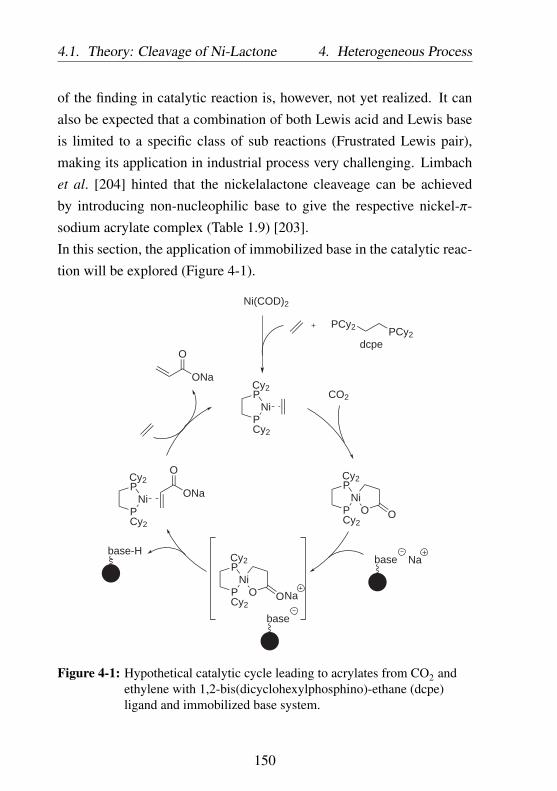
4.1. Theory: Cleavage of Ni-Lactone 4. Heterogeneous Process
of the finding in catalytic reaction is, however, not yet realized. It canalso be expected that a combination of both Lewis acid and Lewis baseis limited to a specific class of sub reactions (Frustrated Lewis pair),making its application in industrial process very challenging. Limbachet al. [204] hinted that the nickelalactone cleaveage can be achievedby introducing non-nucleophilic base to give the respective nickel-π-sodium acrylate complex (Table 1.9) [203].In this section, the application of immobilized base in the catalytic reac-tion will be explored (Figure 4-1).
CO2
ONa
O
Ni(COD)2
PCy2PCy2
dcpe
PNi
PONa
O
PNi
P
Cy2
Cy2
Cy2
Cy2
PNi
PCy2
Cy2
O O
PNi
PCy2
Cy2
O O
Nabase
base
base-H
Na
Figure 4-1: Hypothetical catalytic cycle leading to acrylates from CO2 andethylene with 1,2-bis(dicyclohexylphosphino)-ethane (dcpe)ligand and immobilized base system.
150

4. Heterogeneous Process 4.2. Process Design Options
4.2 Process Design Options
Use of immobilized base would significantly simplify the process. Thecatalytic acrylate formation can be carried out continuously while at thesame time the sodium acrylate product can be isolated and the immo-bilized base can be recycled or regenerated. Contrary to the previousprocesses (Process 1.1, 1.2, 1.3, and 2), the application of immobilizedbase results in a significant process simplification. Process 3 illustratedin Figure 4-2 is based on experimental data discussed in the next section4.3 (Table 4.1 Entry 9): 0.1 mmol (dcpe)-nickelalactone complex tofacilitate nickelalactone formation combined with immobilized sodium2-fluorophenoxide, 100 eq. NaH as cation (Na+) source, and 50 mLTHF as solvent with operating temperature of 100 ○C and 10 bar ethy-lene and 20 bar CO2. The preparation of immobilized base will befurther discussed in section 4.3.1. The process can be carried out in one-pot reaction: the catalytic species (dcpe)-nickelalactone is dissolved inTHF and mixed with immobilized base and NaH. After the suspensionis transferred into the reactor, the autoclave is stirred and pressurizedwith 10 bar ethylene and 20 bar CO2 and heated to 100 ○C. Two stepsfiltration is applied in the post-processing. In the first filtration step,a part of the suspension from the reactor is continuously filtrated toseparate the filtrate containing active metal complex solution and thesolid consisting of immobilized base and sodium acrylate product. Thefiltrate with the metal complex solution can be mixed with immobilizedbase and NaH and directly reintroduced into the reactor, without anycontact with other harmful oxidizing agent. The solid mixture of immo-bilized base and sodium acrylate can be separated by firstly dissolvingthe sodium acrylate product in water followed with a second filtration toseparate the immobilized base, which is insoluble in water. The sodiumacrylate solution can be dried or directly polymerized. The immobilized
151

4.2. Process Design Options 4. Heterogeneous Process
Nickel complexSolvent
Immobilized BaseNaOH or NaH
CO2Ethylene
Filtration:Product separation
Sodium acrylate
Sodium acrylateImmobilized base
Water
Pretreatmentwith NaOH or NaH
CO2 Ethylene
100 °C
Reactorcontinuous mode
100 °C
50 °C
30 °C
25 °C
80 °C
30 °CSolvent
Stripping100 °C, 0.3 bar
TOF: 4.3 ·10-4 s-1
Figure 4-2: Process 3: Use of a molecular catalyst nickel complex andimmobilized base in catalytic acrylate reaction.
152

4. Heterogeneous Process 4.3. Application of the Immobilized Bases
base is reclaimed and dried to remove water. Due to the high stabilityof immobilized base, conventional drying in air or in vacuum at 100 ○Ccan be carried out in this step. The immobilized base is reactivated withNaH-THF suspension or NaOH before reuse in catalytic reaction. Incase of reactivation with NaOH aqueous solution, the immobilized basehas to be completely dried from water.Process 3 offers not only high activity of classical homogeneous metalcomplex, but also facile and efficient product isolation and base re-cycling. In addition, the contact between metal complex catalyst andharmful oxidizing agent can be minimized, thus improving the lifetimeof the catalyst greatly. The use of filtration to separate the metal com-plex, immobilized base, and sodium acrylate product simplifies the pro-cess and reduces the operational and the overall investment cost. Fromthe engineering point of view, process 3 is the most industrially relevantcompared to process 1 and 2 discussed before. Improvement of thecatalytic activity would make sodium acrylate production from ethyleneand CO2 industrially attractive. This can be achieved by increasing theactivity of either the metal complex or the base used for the catalyticreaction.
4.3 Application of the Immobilized Bases
In this work, several immobilized bases based on the findings in Chapter2.1 (tertiary amine base) and the publication of Limbach et al [203].(alkoxide base) were investigated and are illustrated in Figure 4-3. Im-mobilized bases B1 - B4 are commercially available and were used incatalytic reaction in combination with NaH as a cation source. Im-mobilized bases B5 and B6 were prepared via anchoring and copoly-merization respectively (Subchapter 4.3.1). Immobilized bases BR7 -
153
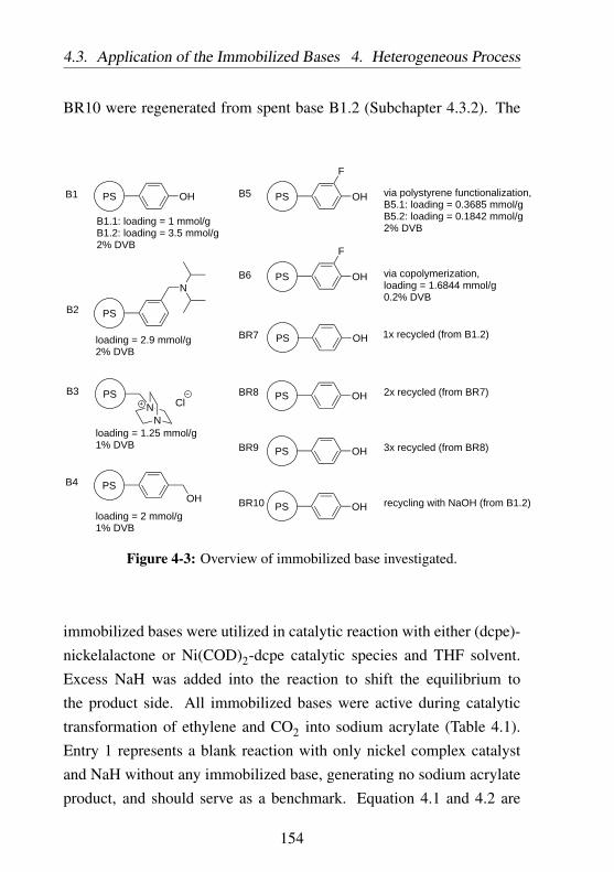
4.3. Application of the Immobilized Bases 4. Heterogeneous Process
BR10 were regenerated from spent base B1.2 (Subchapter 4.3.2). The
OHPS
PS
N
PS
NN Cl
PSOH
OHPS
F
B1
B2
B3
B4
B5
B6
BR7
BR8
OHPS
F
OHPS
OHPS
1x recycled (from B1.2)
2x recycled (from BR7)
via copolymerization,loading = 1.6844 mmol/g0.2% DVB
via polystyrene functionalization,B5.1: loading = 0.3685 mmol/gB5.2: loading = 0.1842 mmol/g2% DVB
BR9 OHPS 3x recycled (from BR8)
BR10 OHPS recycling with NaOH (from B1.2)
B1.1: loading = 1 mmol/gB1.2: loading = 3.5 mmol/g2% DVB
loading = 2.9 mmol/g2% DVB
loading = 1.25 mmol/g1% DVB
loading = 2 mmol/g1% DVB
Figure 4-3: Overview of immobilized base investigated.
immobilized bases were utilized in catalytic reaction with either (dcpe)-nickelalactone or Ni(COD)2-dcpe catalytic species and THF solvent.Excess NaH was added into the reaction to shift the equilibrium tothe product side. All immobilized bases were active during catalytictransformation of ethylene and CO2 into sodium acrylate (Table 4.1).Entry 1 represents a blank reaction with only nickel complex catalystand NaH without any immobilized base, generating no sodium acrylateproduct, and should serve as a benchmark. Equation 4.1 and 4.2 are
154

4. Heterogeneous Process 4.3. Application of the Immobilized Bases
introduced to better evaluate the effectivity of immobilized base duringcatalytic reaction:
TONBase =TONnBase
(4.1)
TOFBase =TOFnBase
(4.2)
Immobilized phenol on polystyrene B1 (Entry 2 - 4) afforded an averageTOF of around 6 - 7⋅10−6 s−1. The catalytic activity is not influenced bythe loading or amount of the immobilized base. Entry 4 shows thatimmobilized base with higher loading yielded a similar TOF value at6.17⋅10−6 s−1. The reaction with immobilized base seems to be limitedby the collisions probability of (dcpe)-nickelalactone and the surfaceof the immobilized base. This phenomenon should occur only withimmobilized base anchored on polystyrene support with low degree ofswelling. Immobilized base anchored on polystyrene support with highdegree of swelling would behave more similar to homogeneous base,thus increasing the mobility of the base and providing an unhinderedaccess of nickelalactone species to the base moiety.Immobilized tertiary amine base B2 and B3 displayed slightly betteractivity. Higher average TOF of about 9⋅10−6 s−1 can be achieved.Normalized TOFBase values shows a 85 % increase in base effectivitycompared to immobilized phenol base B1. Immobilized benzyl alcoholB4 showed the highest TOF of all commercial bases investigated inthis work (Entry 7). In term of base effectivity, TOFBase of 4.22⋅10−6
mmol−1 s−1 can be achieved, which is at least two times more effectivethan immobilized phenol base B1 (TOFBase 2.18⋅10−6 mmol−1 s−1) and
155

4.3. Application of the Immobilized Bases 4. Heterogeneous Process
17 % more active than tertiary amine immobilized at polystyrene sup-port B2 and B3 (TOFBase 3.72⋅10−6 mmol−1 s−1 and 3.61⋅10−6 mmol−1
s−1 respectively). Benzyl alcohol may offer less steric hindered hy-droxyl moiety, thus increasing the probability of contacting the nickel-alactone species.
156
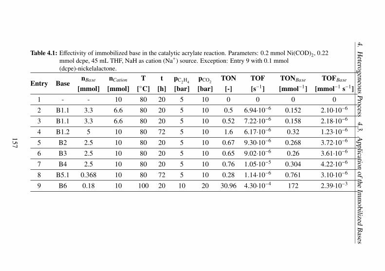
4.H
eterogeneousProcess
4.3.A
pplicationofthe
Imm
obilizedB
ases
Table 4.1: Effectivity of immobilized base in the catalytic acrylate reaction. Parameters: 0.2 mmol Ni(COD)2, 0.22mmol dcpe, 45 mL THF, NaH as cation (Na+) source. Exception: Entry 9 with 0.1 mmol(dcpe)-nickelalactone.
Entry BasenBase nCation T t pC2H4
pCO2TON TOF TONBase TOFBase
[mmol] [mmol] [○C] [h] [bar] [bar] [-] [s−1] [mmol−1] [mmol−1 s−1]1 - - 10 80 20 5 10 0 0 0 0
2 B1.1 3.3 6.6 80 20 5 10 0.5 6.94⋅10−6 0.152 2.10⋅10−6
3 B1.1 3.3 6.6 80 20 5 10 0.52 7.22⋅10−6 0.158 2.18⋅10−6
4 B1.2 5 10 80 72 5 10 1.6 6.17⋅10−6 0.32 1.23⋅10−6
5 B2 2.5 10 80 20 5 10 0.67 9.30⋅10−6 0.268 3.72⋅10−6
6 B3 2.5 10 80 20 5 10 0.65 9.02⋅10−6 0.26 3.61⋅10−6
7 B4 2.5 10 80 20 5 10 0.76 1.05⋅10−5 0.304 4.22⋅10−6
8 B5.1 0.368 10 80 72 5 10 0.28 1.14⋅10−6 0.761 3.10⋅10−6
9 B6 0.18 10 100 20 10 20 30.96 4.30⋅10−4 172 2.39⋅10−3
157
4.3. Application of the Immobilized Bases 4. Heterogeneous Process
4.3.1 Design of the Immobilized Base
Developing an immobilized base, which is active in one-pot ethyleneand CO2 coupling to sodium acrylate, is of huge interest to furtheroptimize the catalytic process. It is also important that the immobilizedbase can be cost-efficiently regenerated. From the results in the previousSubchapter 4.3, two different classes of active immobilized bases canbe identified: immobilized alkoxides and immobilized tertiary aminebases. This chapter addresses the development of immobilized alkoxidebase system, which can be utilized in one-pot catalytic acrylate reaction.There are two limitations, which make the application of commerciallyavailable immobilized bases difficult:
• Side reactions with CO2.
• High divinylbenzene content in the polymer resulting in lowswelling degree. The swelling degree affects the mobility of theimmobilized base and accessibility of the base moiety and thusthe effectivity of the base in catalytic reaction.
As already described in the previous Subchapter 4.3, it has been discov-ered that immobilized sodium phenoxide are active bases for the synthe-sis of sodium acrylate in a one-pot reaction. However, it is known thatsodium phenoxide reacts with CO2 in a Kolbe-Schmitt reaction (Figure4-4) [50–53]. Reducing the base reactivity toward CO2 can be achieved,for example by introducing an electron withdrawing group at the ortho-or para- position to improve the distribution of the electron density (Fig-ure 4-5). Phenol is strongly activated at the ortho- and para- position,while 2-fluorophenol and 4-fluorophenol display an evenly distributedelectron density. The fluorine atom is the most electronegative elementwith relatively small atom radius, resulting in a very close proximityto the carbon atom. Fluorine atom is therefore capable of removing
158

4. Heterogeneous Process 4.3. Application of the Immobilized Bases
O ONa
Na
OCO
+
O
O
ONa
OO
O
H
OH
O
OOH
O
OH
H+
Figure 4-4: Kolbe-Schmitt reaction: aromatic electrophilic substitution ofsodium phenoxide with CO2 [50–53].
electron density from the benzene ring, thus preventing the electrophilicaromatic substitution at the phenol ring.
ONa ONaF
ONa
F
Figure 4-5: Activated position for aromatic electrophilic substitution. Reddot: activation due to ONa moiety. Blue dot: activation due to Fmoiety.
For immobilized bases, it is important to ensure high accessibility of theactive moiety, which is in this case the -ONa group. The anchoring istherefore performed at the para position while F atom is attached at theortho position. In this work, the immobilized 2-fluorophenol analogueswere prepared using two different synthetic routes:
159

4.3. Application of the Immobilized Bases 4. Heterogeneous Process
Direct anchoring of 2-fluorophenol onto polystyrene support withBr functionality
The anchoring was achieved via Grignard reaction to form C-C bondbetween the linker of polystyrene support PS05 and the 2-fluoro-4-bromo-phenol. To prevent side reaction, the hydroxyl moiety of 2-
PSBr
PS05
Br loading = 2.8 mmol/g
Figure 4-6: Support used for base immobilization via direct anchoring route.
fluoro-4-bromo-phenol was first protected with tert-butyldimethylsilyl(TBDMS) group. tert-butyldimethylsilyl ethers are stable toward ba-sic reagents and can be removed with tetrabutylammonium flouride(TBAF). Introduction of silyl protecting group was carried out with tert-butyldimethylsilyl chloride and 2 eq. imidazole in N,N-dimethylformamideat 25 ○C for 18 hours. After liquid-liquid extraction with hexane/water,drying (MgSO4), and vacuum evaporation, pure tert-butyldimethylsilyl-2-fluoro-4-bromo-phenolate (yield = 85.4 %) was obtained. The pro-tected phenol was then reacted with magnesium metal in THF at 50○C to form the Grignard reagent. After cooling to 0 ○C, the Grignardreagent was reacted with the electrophilic linker of polystyrene supportfor 24 hours. The solid product was filtrated, washed, and treated with1 M TBAF in THF at 0 ○C for 30 minutes to remove the silyl protectinggroup. Since the anchoring route involves a slow reaction between asolid and fluid, the long time stability of the Grignard reagent affectsthe final base loading on the support significantly. The stability ofthe Grignard reagents depends on the temperature, at which the an-choring takes place. While anchoring at 0 ○C for 24 hours yielded 2-fluorophenol loading of 0.3685 mmol/g (Table 4.2 Entry 1), anchoring
160

4. Heterogeneous Process 4.3. Application of the Immobilized Bases
PSBr
OHF
Br
OTBDMSF
Br
TBDMSClImidazol
DMF
25 °C, 18 h
OTBDMSF
MgBr
Mg/I2THF
50 °C, 1h
0 °C, 20 h
PS
OTBDMS
F
1 M TBAF/THF
0 °C, 30 min
PS
OH
F
B5
Figure 4-7: Anchoring of 2-fluorophenol onto polystyrene support.
at the same conditions but at 25 ○C resulting in much lower base loadingat 0.1842 mmol/g (Entry 2). Due to low contact probability between the
Table 4.2: Anchoring of 2-fluorophenol on the polystyrene support PS05.Base loading values were derived from elemental analysis results.X = Br moiety on the catalyst support.Base:X ratio = 0.5 mmol/mmol. Degree of anchoring = ratio ofanchored base to base starting material.
Entry Samplename Conditions
Base loadingon support[mmol/g]
Degree ofanchoring
[%]
1 B5.1 24h at 0 ○C 0.3685 26.32
2 B5.2 24h at 25 ○C 0.1842 13.16
161

4.3. Application of the Immobilized Bases 4. Heterogeneous Process
elctrophile attached to the solid material and the nucleophilic phenolatein the liquid phase, the anchoring approach results in low loading ofthe base. Similar to the preparation of immobilized ligand discussedin Subchapter 3.3.2, the final base loading on the support material isgreatly influenced by the physical properties of the support itself: thesurface area, the pore size, and the linker loading. After reaching a cer-tain dcpe loading, the support becomes overcrowded and the resultingsteric prevents any further anchoring of the base at the support. Anyunreacted base remaining in the solution was removed during washing.The direct anchoring strategy is thus ineffective; only a small fraction ofthe 2-fluorophenol educts could be anchored. In addition, since directanchoring approach used a commercially available polystyrene supportwith 2 % divinylbenzene crosslinker (PS05, Figure 4-6), the secondlimitation associated with commercial immobilized base concerning thedegree of swelling can not be addressed. Alternative preparation route toimmobilized 2-fluorophenol via copolymerization is therefore exploredin the next section.
Copolymerization of 2-fluoro-4-vinylphenol, styrene, and 1,4-divinyl-benzene
The copolymerization approach allows a full control of the propertiesof the immobilized base. Materials with a high loading of the activemoiety and a specific degree of swelling can be precisely tailored.Copolymerization can be performed by firstly preparing the necessarymonomer. In this work, 2-fluoro-4-vinylphenol monomer was preparedby introducing a vinyl side chain to 2-fluoro-4-bromophenol. This wasachieved via cross-coupling reaction of 2-fluoro-4-bromophenol withvinyl Grignard reagent, which took place in the presence of 1 mol%
162

4. Heterogeneous Process 4.3. Application of the Immobilized Bases
OHF
Br
MgBr+
1mol% PdCl2dppfTHF
-78°C/10minreflux at 80°C/2h
2
OHF
0.5 mol% AIBNChlorobenzene60°C/12h/Argon
OHF
nm
Figure 4-8: Immobilization of 2-fluorophenol via copolymerization.
[1,1-bis(diphenylphosphino)ferrocene]dichloropalladium (PdCl2dppf) cat-alyst at 80 ○C for 2 hours. Two eq. of Grignard reagent are requiredto protect the hydroxy groups, which can interfere during the reaction.After 2 hours, the reaction mixture was cooled, quenched with 1 M HClsolution and extracted with diethylether. The product was recrystal-lized to achieve pure 2-fluoro-4-vinylphenol monomer. The productwas copolymerized with styrene and 1,4-divinylbenzene in the pres-ence of 2,2-azobis(2-methylpropionitrile) (AIBN) as radical initiator at60 ○C for 12 hours. The ratio of 2-fluoro-4-vinylphenol:styrene:1,4-divinylbenzene was 3:7:0.2. After purification, the polymer product wascharacterized with elemental analysis to give an immobilized base withan active moiety loading of about 1.6844 mmol/g.
163

4.3. Application of the Immobilized Bases 4. Heterogeneous Process
Both immobilized 2-fluorophenol prepared via anchoring (B5) and copoly-merization (B6) routes displayed remarkable catalytic activities. Cat-alytic experiment with immobilized 2-fluorophenol base B5.1 affordeda TOFBase value of about 4.22⋅10−6 mmol−1 s−1 (Table 4.1 Entry 8). Theimmobilized base B5.1 was prepared by anchoring 2-fluorophenol moi-ety onto a commercially available polystyrene support PS05, which isprepared via copolymerization with 2 % divinylbenzene as crosslinker.The high amount of crosslinker increases the polymer strength, hard-ness, and stability toward solvent and heat. When polymer chains areconnected with each other or crosslinked, they lose some of their abilityto expand or move as individual polymer strain. In polymers with lowdegree of crosslinking, organic solvent may separate the polymer chainswhich are not covalently linked. The polymer chains may expand, re-sulting in the swelling phenomenon of the polymer. As little as 0.5 %divinylbenzene in a styrene polymerization makes the polymer insolu-ble, yet still swellable. This may have an important consequence in theeffectivity of the base: immobilized base B6, which was copolymerizedwith only 0.2 % divinylbenzene, thus low degree of crosslinking andhigh degree of swelling, yielded a significantly higher TOF, at 4.3⋅10−4
s−1 (Table 4.1 Entry 9). In term of base effectivity, this would translateto a TOFBase of 2.39⋅10−3 mmol−1 s−1. Low degree of crosslinking ofthe immobilized base B6 allows the solvent to partially "dissolve" thepolymer. Immobilized base would behave more similar to homogeneousbase, thus increasing the mobility of the base and providing an unhin-dered access of nickelalactone species to the base moiety.
164

4. Heterogeneous Process 4.3. Application of the Immobilized Bases
4.3.2 Recycling of the Immobilized Base System
Recyclability of immobilized base is one of the most important factors inthe process 3. Highly recyclable material will contribute to efficient con-tinuous process. The recyclability of immobilized base was investigatedwith commercial B1.2 as a representative model. The catalytic reactionwas carried out with (dcpe)-nickelalactone catalyst and THF solventwith 10 bar ethylene and 20 bar CO2 at 100 ○C for 20 hours (Table4.3). Reference reaction with fresh immobilized base B1.2 delivered aTON of 1.57 (Entry 1). After catalytic reaction, the spent base B1.2 wasregenerated by five-times washing with:
• 1 M aqueous HCl solution to liberate all hydroxyl groups and
• ethanol to remove any chemisorbed nickel complex species.
The regenerated immobilized bases were dried at 50 ○C in vacuumovernight to remove all volatile impurities to give immobilized phenolbase. The base was suspended in THF and activated by the addition ofNaH. BR7, BR8, and BR9 denote recycled immobilized base after one,two, and three catalytic reactions respectively.Alternatively, the spent immobilized base from Entry 1 can also be re-generated with 1 M aqueous NaOH solution instead of HCl. Contrary toacidic regeneration with HCl, the base recycling with NaOH was endedwith NaOH wash to afford immobilized sodium phenolate base. Afterregeneration, the immobilized base BR10 was dried at 50 ○C in vacuumovernight to remove all volatile impurities.The immobilized bases BR7 - BR10 were tested in the catalytic reactionunder the same condition as Entry 1. The amount of recycled immobi-lized base in the catalytic reaction was not constant due to significantloss during recycling step. However, as already mentioned in the pre-vious section 4.3, the catalytic activity is not influenced by the amount
165

4.3. Application of the Immobilized Bases 4. Heterogeneous Process
of the immobilized base B1 present during the catalytic reaction butis limited by the collisions probability of (dcpe)-nickelalactone and thesurface of the solid immobilized base B1. The immobilized base canthus be assumed to be available in excess during the reaction and isnot rate limiting. The effectivity of base recycling can be quantified byintroducing a dimensionless quantity, which normalizes the TON of therecycled base with the value in the previous catalytic reaction:
Activity recovery =TON a f ter recycling
TON be f ore recycling(4.3)
In general, all recycled immobilized bases displayed the ability to fa-cilitate the nickelalactone cleavage (Figure 4-9). Reaction with immo-bilized base after one time recycling (Table 4.3 Entry 2: TON 1.18)produced 25 % less sodium acrylate compared to the reaction with freshimmobilized phenol B1.2 (Entry 1: TON 1.57). On the other hand,immobilized base after two times recycling regained its full effectivity(Entry 3: TON 1.29), which is 109 % TON value of immobilized baseafter one time recycling. Similarly, the effectivity of immobilized baseafter three times recycling (Entry 4: TON 1.16) is comparable to thatafter two times recycling. Further investigations are necessary to eluci-date the limitation of recycled base.On the other hand, the application of BR10 base, which is regeneratedwith NaOH, resulted in significantly lower activity (Entry 5). Catalyticreaction with BR10 yielded sodium acrylate with TON of 0.54, whichrepresents only 47 % activity of fresh immobilized base. The limited ac-tivity of BR10 base can be related with trace water in the recovered ma-terial. While acidic regeneration with HCl was completed with washingwith ethanol to remove traces water followed with vacuum drying, waterremoval in NaOH regenerated immobilized base was limited to vacuum
166

4. Heterogeneous Process 4.4. Conclusion
drying, which may result in higher water content in the recovered BR10base.
Table 4.3: Recyclability of immobilized sodium phenoxide in the catalyticacrylate reaction. Parameters: 0.2 mmol (dcpe)-nickelalactone,Base loading = 3.5 mmol/g, 45 mL THF, 10 bar ethylene, 20 barCO2, 100 ○C, and 20 hours reaction. Cation source: 10 mmol NaH.
Entry Base nBase [mmol] TON [-] Activity recovery[%]
1 B1.2 5 1.57 100
2 BR7 5 1.18 75
3 BR8 4.255 1.29 109
4 BR9 2.882 1.16 90
5 BR10 5 0.54 47
4.4 Conclusion
A process utilizing homogeneous nickel complex combined with immo-bilized base system can be considered as the most industrially feasibleone from all four process concepts previously discussed. In addition tomore superior catalytic activity comparable to its molecular catalyst -alkoxide and amine-NaH base system (Process 1.1, 1.2, and 1.3), theprocess with immobilized base offers excellent product separation andbase recycling. The post reaction process requires a simple two stepsfiltration to separate the sodium acrylate product and to recover the im-mobilized base. Immobilized base can be regenerated with either NaHor cost-efficient NaOH as alternative. This would significantly reducethe energy consumption and the investment cost for a complex extrac-tion process required in other concepts described before. In addition,
167

4.4. Conclusion 4. Heterogeneous Process
1.57
1.181.29
1.16
fresh base first recycling second recycling third recycling0.0
0.2
0.4
0.6
0.8
1.0
1.2
1.4
1.6
TON
Na
Acr
ylat
e [-]
Immobilized Base B1.2
Figure 4-9: Recyclability of immobilized sodium phenoxide in the catalyticacrylate reaction.
168

4. Heterogeneous Process 4.4. Conclusion
the process can also be carried out continuously, which would reducethe labor cost and increase the overall efficiency. The catalytic nickelcomplex species remains during the whole process in the reactor underinert atmosphere and thus retains its catalytic activity during the wholeprocess.The improvement in the catalytic activity of the metal complex as wellas the effectivity of the immobilized base would translate to a highlyefficient chemical process. Effectiveness of the immobilized base canbe achieved by decreasing the reactivity of the base towards CO2 andincreasing the swell-ability of the material. The latter factor wouldincrease the mobility of the active base moiety during catalytic reac-tion. These two factors are key points in designing a highly effec-tive immobilized base. Immobilized 2-fluorophenol base prepared viacopolymerization of the monomer with 0.2 % divinylbenzene provided apromising candidate, enabling a TON of 30.94 in catalytic reaction with(dcpe)-nickelactone (TOF 4.30⋅10−4 s−1). Assuming a continuous semibatch reactor (process concept 3) with 0.2 mmol nickel dcpe complexmolecular catalyst, the highest TOF achievable in this work of about4.30⋅10−4 s−1 represents a space-time-yield (STY) of:
S TY =TOF ⋅ nCatalyst ⋅ MS odium Acrylate
Vreactor
S TY = 4.86 ⋅ 10−4 kg S odium Acrylate
L ⋅ hwith MS odium Acrylate = 94.04 g/mol and Vreactor = 0.060 L.The recyclability of the catalyst is another important aspect required inthis process. It is noteworthy that successful recycling of the base wasdemonstrated. Base regeneration could be achieved either with acidicHCl solution or basic NaOH solution. Acidic HCl regeneration resultedin high base activity, comparable to that of the fresh immobilized base.
169

4.4. Conclusion 4. Heterogeneous Process
Basic regeneration with NaOH resulted in a material which activity(TON 0.54) was much lower than that of the fresh immobilized base(TON 1.57).In addition to the high catalytic activity of the reaction utilizing molec-ular catalyst and immobilized base, this process concept also benefitsfrom the significantly lower separation and recycle costs. Moreover,the separation of the molecular catalyst from the product - immobilizedbase mixture can be achieved with a filtration step, which minimizes thecontact of the active molecular catalyst with any harmful compounds.
170
Chapter 5
Conclusions
The molecular nickel complex in combination with alkoxide base wasreported as the only working catalytic reaction of ethylene and CO2
leading to sodium acrylate [203]. The system is constrained to two-pot process with nickelalactone formation in the first step and nickel-alactone cleavage in the second step. The two-pot process preventsthe unintended side reaction of the alkoxide base with CO2 forming aninactive semi-carbonate. Unfortunately, the formation of a conjugateacid of the alkoxide base during reaction is unavoidable. The resultingconjugate acid reacts with and deactivates the nickel complex catalyst.Moreover, liquid-liquid extraction is required to separate the water sol-uble sodium acrylate product from the nickel complex solution. In thisstep, traces of oxygen or other impurities may oxidize and deactivatethe nickel complex catalyst, which complicates the recyclability of thecatalyst. Limbach et al [203]. reported a catalytic reaction with TONof up to 10 with a combination of (dtbpe)-nickel complex and NaOtBubase. Limitations of the state-of-the-art process reported by Limbach etal [203]. are successfully addressed in this work. Three different systemconcepts are proposed:
171

5. Conclusions
• Homogeneous process with a molecular nickel complex catalystand amine-NaH base systems (Chapter 2).
• Heterogeneous process with an immobilized nickel complex cat-alyst and amine-NaH base systems (Chapter 3).
• Heterogeneous process with a molecular nickel complex catalystand an immobilized base (Chapter 4).
The application of CO2-stable amine-NaH base system allows one-potprocess, which reduces the complexity of the process greatly. Sev-eral tertiary amine alkali hydride combinations have been successfullyidentified as an effective system for the nickelalactone cleavage. Acombinaton of (dcpe)-nickelalactone catalyst with triethylamine-NaHdelivered a TON of 18.84 (TOF 7.27⋅10−5 s−1). In addition, the ap-plication of hydrophobic amines further improves the recyclability ofthe base and simplifies the post-treatment greatly. Liquid-liquid extrac-tion separates the organic base containing hydrophobic base and nickelcomplex catalyst from the sodium acrylate in the aqueous phase. Aftersimple pre-treatment of the organic phase to remove remaining water,the base along with the nickel complex catalyst can be directly reused.The combination of nickel dcpe complex with N,N-dimethylaniline,N,N-diethylaniline, trioctylamine and NaH yielded sodium acrylate withTON of up to 3.93, 2.65, and 16.91 respectively.Heterogenization of the nickel complex catalyst or base allows the pro-cess to be run continuously. The sensitive nickel complex remains inthe reactor without contact with other impurities, thus increasing thelifetime of the catalyst during the catalytic reaction.Heterogenization of the nickel complex was achieved via anchoring onsilica and polystyrene support materials. Metal complex loading of upto 0.1566 mmol/g and 0.134 mmol/g can be achieve with silica gel and
172

5. Conclusions
polystyrene support respectively. MAS NMR investigations confirmedthe presence of active dcpe immobilized on the surface of the supportmaterials. Immobilized (dcpe)-nickelalactone intermediate species isinstable and decomposes readily. The immobilized nickel complexon polystyrene support delivered catalytic activity with TON of up to1.42 with triethylamine-NaH base combination. On the other hand,immobilized nickel complex on silica support did not display observablesodium acrylate product. This might be due to strong interaction of theactive nickel complex with either the silanol moiety or the chemisorbedoxygen, which may preset on the inner and outer surface of the support.A combination of homogeneous nickel complex and immobilized baseshowed high activity, especially in case of immobilized sodium 2-fluorophenolate. Immobilized sodium 2-fluorophenolate was preparedeither via direct anchoring on linker-functionalized polystyrene supportor via copolymerization of the 2-fluoro-4-vinylphenol monomer withstyrene and 1,4-divinylbenzene in the presence of radical initiator. Acombination of (dcpe)-nickelalactone catalyst with immobilized sodium2-fluorophenolate delivered a TON of up to 30.94 (TOF 4.30⋅10−4 s−1).The immobilized sodium 2-fluorophenolate was prepared via copoly-merization with 0.2 % divinylbenzene, resulting in highly swellablematerial with exceptional accessibility of the base moiety.Recycling of the immobilized base was successfully represented withcommercially available immobilized phenol on polystyrene. The re-cyclability of the immobilized base is crucial and can be applied in ahighly efficient continuous process. The solid immobilized base andsodium acrylate can be continuously separated from the reactor withsimple filtration step. The molecular nickel complex catalyst dissolvedin organic solvent can be directly mixed with regenerated immobilizedbase and reintroduced into the reactor. The immobilized base can be
173
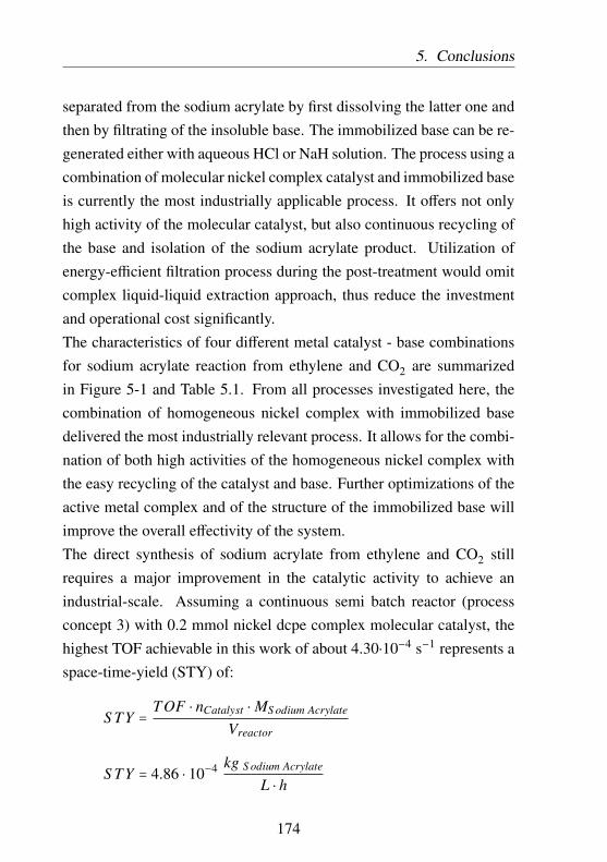
5. Conclusions
separated from the sodium acrylate by first dissolving the latter one andthen by filtrating of the insoluble base. The immobilized base can be re-generated either with aqueous HCl or NaH solution. The process using acombination of molecular nickel complex catalyst and immobilized baseis currently the most industrially applicable process. It offers not onlyhigh activity of the molecular catalyst, but also continuous recycling ofthe base and isolation of the sodium acrylate product. Utilization ofenergy-efficient filtration process during the post-treatment would omitcomplex liquid-liquid extraction approach, thus reduce the investmentand operational cost significantly.The characteristics of four different metal catalyst - base combinationsfor sodium acrylate reaction from ethylene and CO2 are summarizedin Figure 5-1 and Table 5.1. From all processes investigated here, thecombination of homogeneous nickel complex with immobilized basedelivered the most industrially relevant process. It allows for the combi-nation of both high activities of the homogeneous nickel complex withthe easy recycling of the catalyst and base. Further optimizations of theactive metal complex and of the structure of the immobilized base willimprove the overall effectivity of the system.The direct synthesis of sodium acrylate from ethylene and CO2 stillrequires a major improvement in the catalytic activity to achieve anindustrial-scale. Assuming a continuous semi batch reactor (processconcept 3) with 0.2 mmol nickel dcpe complex molecular catalyst, thehighest TOF achievable in this work of about 4.30⋅10−4 s−1 represents aspace-time-yield (STY) of:
S TY =TOF ⋅ nCatalyst ⋅ MS odium Acrylate
Vreactor
S TY = 4.86 ⋅ 10−4 kg S odium Acrylate
L ⋅ h
174

5. Conclusions
with MS odium Acrylate = 94.04 g/mol and Vreactor = 0.060 L. An ideal STYvalue [273] between 0.01 - 1 kg
L⋅h for an industrial process would requirea TOF of about 8.86⋅10−3 - 0.886 s−1, which is achievable with a moreactive nickel complex and an improved base system.
175

5.C
onclusions
Figure 5-1: Process profitability of different metal catalyst - base combinations for sodium acrylate reaction fromethylene and CO2. Values were calculated from the experiments with the highest yield in sodium acrylate.
176

5.C
onclusions
Table 5.1: Comparison of different metal catalyst - base combinations for sodium acrylate reaction from ethylene andCO2.
Molecular nickel complex catalyst -alkoxide [203]
Molecular nickel complex catalyst -amine-NaH
Catalytic activityHigh, however catalyst deactivates due toreaction with the conjugate acid of thebase
High
Catalyst lifetime
Low, may be oxidized during productseparation (liquid - liquid extraction) andside reaction with conjugate acid of thebase
Low, may be oxidized during productseparation
Product separation Difficult, liquid-liquid extraction fromreaction mixture
Moderate
Base recycling Difficult, conjugate acid of the baseforms azeotrope with water
Good, especially for hydrophobic amine
Process (Product sep-aration and base recy-cling)
Energy intensiveModerate (hydrophilic amine) - Good(hydrophobic amine)
177

5.C
onclusions
Table 5.1: (cont.)
Immobilized nickel complex catalyst -amine-NaH
Molecular nickel complex catalyst -immobilized base
Catalytic activity
Low, due to low mobility of the immobi-lized catalyst, thus lower contact proba-bility between nickelalactone species onthe catalyst surface and base in the liquidphase
High, especially when highly swellablepolymer support is used to immobilizebase
Catalyst lifetime Good, catalyst can be separated beforeliquid - liquid extraction
Good, catalyst can be separated and di-rectly used for the catalytic reaction be-fore contact with other compounds
Product separation Easy Excellent (energy efficient filtration)
Base recycling Good, especially for hydrophobic amine Excellent, only requires simple filtration
Process (Product sep-aration and base recy-cling)
Moderate (hydrophilic amine) - Good(hydrophobic amine)
Excellent (energy efficient filtration)
178

Appendix A
Experimental Section
Unless otherwise stated in this section, all commercially available chem-icals were directly used. For reactions where oxygen and water contentsare crucial, the solvents were degassed (e.g. Freeze-Pump-Thaw) and/ordried with activated molecular sieves or elementary sodium.1H, 13C, and 31P NMR spectra were recorded on Bruker Avance 50,125, 200 or 500 MHz spectrometers and were referenced to the residualproton (1H) or carbon (13C) resonance peaks of the solvent. Chemicalshifts (δ) are reported in ppm. Elemental analysis were recorded bythe analytical service of BASF. MAS NMR spectra were recorded on aBruker MSL-400 spectrometer by apl. Prof. Dr. Michael Hunger at theUniversity of Stuttgart.
A.1 High Throughput Experimentation
The close connection between the catalyst and the reaction conditionshas always led to a multidimensional effort with extensive resources.
179

A.1. High Throughput Experimentation A. Experimental Section
The introduction of high throughput experimentation with the empha-sis on miniaturization, parallelization, and automation of experimentsallows for increased experimental load without additional time and per-sonal resources, thus accelerating the research and development process.Over the past years, high throughput experimentation has facilitatedsignificant advances in the discovery and optimization of chemical pro-cesses. High throughput experimentation can be applied in the synthesisof new or optimized catalyst as well as the subsequent catalyst screen-ing.In this work, high throughput experimentation was carried out for thetesting of the catalysts and the base systems in a 4-fold 160 mL titaniumautoclave system and 6-fold 60 mL steel autoclave system. The reac-tion conditions in each autoclave can be individually adjusted, offeringa broad possibility of performing several experiments in parallel. Asimplified schematic drawing of a single autoclave unit is illustratedin Figure A-2 below. Each autoclave is equipped with a charger port,allowing the introduction of chemicals under inert condition. Argonwas used to pressurize and facilitate inert transfer of the chemicals intothe autoclave. Ethylene, CO2, and optionally nitrogen as well as argoncan be introduced into the reactor via gas inlet 1 and 2. A fourth portline was used as a gas release mechanism. Each autoclave was alsoequipped with a rupture disk to protect the vessel from any unintendedoverpressurization. The temperature and pressure inside each autoclavewere individually controlled and recorded. Two autoclave types wereused for the screening purpose (Table A.1).
180

A. Experimental Section A.1. High Throughput Experimentation
Exhaust/ Vacuum
Charger port
Gas 2
Gas 1
PI
TIC
Ch
arge
r
Figure A-1: Schematic drawing of a single autoclave unit.
Table A.1: Types of autoclave used for the screening purpose.
Titanium autoclave Steel autoclave
Max volume [mL] 160 60
Max operating80 180
pressure [bar]
Max operating120 200
temperature [○C]
Chemical resistance Very good No corrosive chemicals
181

A.1.
High
ThroughputE
xperimentation
A.
Experim
entalSection
N2
Argon
C2H4
CO2
PI
TIC
Exhaust
PI
TIC
Charger
Charger
Vacuum
Figure A-2: Schematic representation of a multi-fold autoclave system (only two autoclaves are shown).
182

A. Experimental Section A.2. Catalytic reaction
The high throughput experimentation is particularly useful in the earlyresearch of a chemical process, where several reaction parameters haveto be identified. The iterative improvement in the catalysis research aswell as in the reaction and process engineering parts will effectively leadto shorter time-to-market.
A.2 Catalytic reaction
One-pot catalytic reaction was performed in a 4-fold 160 mL titaniumautoclave system and 6-fold 60 mL steel autoclave system. All reactantswere prepared under inert conditions in a glovebox and transferred intothe autoclave via a charger. After all required components were success-fully introduced, the autoclave was mechanically stirred (2000 rpm) andpressurized with ethylene until the solvent was saturated (15 minutes).The autoclave was then further pressurized with CO2 until saturation (15minutes). After reaching a constant pressure, the autoclave was heatedup to a certain temperature within five minutes. After the indicatedreaction duration, the autoclave was cooled to room temperature anddepressurized. Unless otherwise stated, the autoclave was opened in airand standard work up procedure was carried out to isolate the sodiumacrylate product.
Work up: Product isolation
A mixture of 10 mL D2O and 10 mL THF was added dropwise into thereaction mixture. Additional 15 mL D2O was added and the mixture
183

A.2. Catalytic reaction A. Experimental Section
was extracted twice with 2 times 20 mL diethylether. Tetramethy-lammonium iodide (NMe4I 0.125 mmol, 25.1 mg) and 2,2,3,3-d4-3-(trimethylsilyl)propionic acid (0.167 mmol, 28.7 mg) were added to theaqueous phase as internal standard.
NMR Quantification
The amount of sodium acrylate product was determined by 1H NMRspectroscopy with two internal standards for quantification. The internalstandards were chosen with the following requirements:
• chemically inert.
• low volatile.
• highly soluble in aqueous phase (D2O).
• simple NMR spectra, with chemical shift in 1H NMR preferablyin the range 0 - 1 ppm or 3 - 3.5 ppm.
The integrated intensity of a resonance due to the analyte nuclei isdirectly proportional to its molar concentration and to the number ofnuclei that gives rise to that resonance:
Concentration ∼Integral Area
Number o f nuclei(A.1)
thus the amount of dissolved sodium acrylate product can be calculatedby comparing the integral of sodium acrylate to that of a standard com-pound of known concentration:
cS odium Acrylate =NAS odium Acrylate ⋅ cS tandard
NAS tandard(A.2)
184

A. Experimental Section A.2. Catalytic reaction
or
nTotal S odium Acrylate produced =NAS odium Acrylate ⋅ nS tandard
NAS tandard(A.3)
with
NA =Integral Area
Number o f nuclei(A.4)
Table A.2: Relevant chemical shift of sodium acrylate and internal standardsin 1H NMR for quantification. Solvent: D2O.
Compound δ [ppm] Number ofproton
Sodium Acrylate 5.65 (dd) 1
2,2,3,3-d4-3-(trimethylsilyl)propionicacid
0 (s) 9
Tetramethylammonium iodide 3.19 (s) 12
Finally TON can be calculated from the amount of sodium acrylaterelative to the amount of (immobilized) catalyst:
TON =nS odium Acrylate
nCatalyst(A.5)
TOF =TON
t(A.6)
Preparation of catalytic species
185

A.2. Catalytic reaction A. Experimental Section
N
NNi
OO
Synthesis of (tmeda)-Nickelalactone [199]: Bis(1,5-cyclooctadiene)nickel(0) (10 g, 36.356 mmol), succinicanhydride (3.032 g, 30.296 mmol) were suspended intmeda (32 mL). The mixture was stirred under Argon at
room temperature for 9 h. The light green complex was filtered, washedthree times with 20 mL diethyl ether and dried in vacuum to give 5.48g light green (tmeda)-Nickelalactone (Yield = 73.24%). 200.15-MHz1H NMR (DMF-d7): δ 0.17 (2H, triplet), 1.58 (2H, triplet), 2.19 (6H,singlet), 2.23 (4H, singlet), 2.35 (6H, singlet). 50.3-MHz 13C NMR(DMF-d7): δ -1.71, 46.32, 48.42, 56.03, 60.87.
PCy2
Cy2P
NiO
O
Synthesis of (dcpe)-Nickelalactone method 1: tmeda-Nickelalactone (4.5 g, 18.22 mmol) and 1.1 eq dcpe(8.470 g, 20.042 mol) were suspended in 100 mL THF.The mixture was stirred under Argon for 16 h at roomtemperature. The yellow product was filtered, washed
with three times 30 mL hexane to remove tmeda and unreacted dcpe.The yellow solid was recrystallized from hexane/THF and dried in vac-uum to give 7.65 g yellow-orange (dcpe)-Nickelalactone powder (Yield= 75.7%). 500.36-MHz 1H NMR (CD2Cl2): δ 0.77 (2H, multiplet), 1.2- 1.5 (22H, multiplet), 1.65 - 1.95 (22H, multiplet), 2.13 (4H, multiplet),2.21 (2H, multiplet). 125.82-MHz 13C NMR (CD2Cl2): δ 0.14, 12.37,17.85, 24.91, 26.71, 27.64, 29.4, 29.87, 30.24, 34.14, 35.92, 37.66.202.55-MHz 31P NMR (CD2Cl2): δ 61.98, 69.36.
PCy2
Cy2P
NiO
O
Synthesis of (dcpe)-Nickelalactone method 2: Bis(1,5-cyclooctadiene)nickel(0) (110 mg, 0.4 mmol) and 1.1 eqdcpe (185.9 mg, 0.44 mmol) were dissolved in 50 mLTHF. The solution was charged into titan autoclave and
186

A. Experimental Section A.2. Catalytic reaction
stirred. The autoclave was pressurized with 5 bars ethy-lene and the mixture was stirred further at 25 ○C for 15 min. Afterthe pressure in autoclave reach equilibrium at 5 bars, the autoclavewas pressurized with 20 bars CO2 and stirred for further 15 min un-til reach equilibrium. The reaction took place at 50 ○C for 3 days.The autoclave was depressurized and the yellow product solution wastaken with syringe. THF was removed in vacuum and the solid wasredissolved in THF and precipitated with hexane to give 44 mg yellow-orange (dcpe)-Nickelalactone powder (Yield = 20 %). 500.36-MHz1H NMR (CD2Cl2): δ 0.77 (2H, multiplet), 1.2 - 1.5 (22H, multiplet),1.65 - 1.95 (22H, multiplet), 2.13 (4H, multiplet), 2.21 (2H, multiplet).125.82-MHz 13C NMR (CD2Cl2): δ 0.14, 12.37, 17.85, 24.91, 26.71,27.64, 29.4, 29.87, 30.24, 34.14, 35.92, 37.66. 202.55-MHz 31P NMR(CD2Cl2): δ 61.98, 69.36.
P
PNi
OO
Synthesis of (BenzP)-Nickelalactone: tmeda-Nickelalactone (87.4 mg, 0.354 mmol) and 1 eq(S,S)-(-)-1,2-bis(t-butylmethylphosphino)benzene (BenzP)(100 mg, 0.354 mmol) were suspended in 2.5 mLTHF. The mixture was stirred under Argon for 16hours at room temperature. The reaction mixture
was filtered, washed with three times 5 mL THF. The filtrate was driedin vacuum and recrystallized from hexane/THF and dried in vacuum togive 17.5 mg orange (BenzP)-Nickelalactone powder (Yield = 12%).500.36-MHz 1H NMR (CD2Cl2): δ 0.99 (1H, multiplet), 1.05 - 1.4(18H, multiplet), 1.57 (6H, multiplet), 2.05 - 2.45 (3H, multiplet), 7.55- 7.75 (4H, multiplet). 125.82-MHz 13C NMR (CD2Cl2): δ 0.09, 4.83,16.65, 27.37, 27.8, 33.1, 34.56, 37.32, 131.03, 132.1, 140.04, 142.33.
187
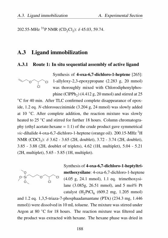
A.3. Ligand immobilization A. Experimental Section
202.55-MHz 31P NMR (CD2Cl2): δ 45.03, 59.74.
A.3 Ligand immobilization
A.3.1 Route 1: In situ sequential assembly of active ligand
O ClCl
Synthesis of 4-oxa-6,7-dichloro-1-heptene [265]:1-allyloxy-2,3-epoxypropane (2.283 g, 20 mmol)was thoroughly mixed with Chlorodiphenylphos-phine (ClPPh2) (4.412 g, 20 mmol) and stirred at 25
○C for 40 min. After TLC confirmed complete disappearance of epox-ide, 1.2 eq. N-chlorosuccinimide (3.204 g, 24 mmol) was slowly addedat 10 ○C. After complete addition, the reaction mixture was slowlyheated to 25 ○C and stirred for further 18 hours. Column chromatogra-phy (ethyl acetate:hexane = 1:1) of the crude product gave symmetricalvic-dihalide 4-oxa-6,7-dichloro-1-heptene (orange oil). 200.15-MHz 1HNMR (CDCl3): δ 3.62 - 3.65 (2H, doublet), 3.72 - 3.74 (2H, doublet),3.85 - 3.88 (2H, doublet of triplets), 4.62 (1H, multiplet), 5.04 - 5.21(2H, multiplet), 5.65 - 5.85 (1H, multiplet).
SiOO
OO Cl
Cl
Synthesis of 4-oxa-6,7-dichloro-1-heptyltri-methoxysilane: 4-oxa-6,7-dichloro-1-heptene(4.05 g, 24.1 mmol), 1.1 eq. trimethoxysi-lane (3.085g, 26.51 mmol), and 5 mol% Ptcatalyst (H2PtCl6 (609.2 mg, 1.205 mmol)
and 1.2 eq. 1,3,5-triaza-7-phosphaadamantane (PTA) (234.3 mg, 1.446mmol)) were dissolved in 10 mL toluene. The mixture was stirred underArgon at 80 ○C for 18 hours. The reaction mixture was filtered andthe product was extracted with hexane. The hexane phase was dried in
188

A. Experimental Section A.3. Ligand immobilization
vacuum and distilled (125 ○C, 67 Pa) to give 5 g colorless 4-oxa-6,7-dichloro-1-heptyltrimethoxysilane oil (Yield = 71.4%). 500.36-MHz1H NMR (toluene−d8): δ 0.87 (2H, multiplet), 1.47 (2H, multiplet),3.51 (9H, singlet), 3.45 (2H, multiplet), 3.5 - 3.7 (4H, multiplet).
SiOO
OO Cl
Cl
SiO2
O
TMS
OTMS
Preparation of vic-chlorides func-tionalized silica [274–276]: SilicaCariact Q-20 was dried in vacuumat 100 ○C for 24 hours. 7 g ofpretreated silica was suspended in100 mL toluene. 3.4 g 4-oxa-6,7-dichloro-1-heptyltrimethoxysilane oilwas added and the suspension was
stirred under reflux for 72 hours. 10 mL distilled water was addedand the condensation was further continued for 48 hours. The mixturewas cooled to room temperature, filtered, washed three times with 50mL distilled water and dried at 200 ○C in vacuum for 4 hours. Thewhite powder was washed three times with 50 mL dry acetone anddried in vacuum at 50 ○C to give g linker functionalized silica. Pro-tection of remaining surface hydroxyl group: at -40 ○C, an excess oftrimethylchlorosilane (TMSCl) was added to the silica product. Themixture was slowly warmed up to 25 ○C and refluxed for 16 hours. Thesolid is filtered off, washed three times with each 50 mL toluene, etherand THF and dried in vacuum at 50 ○C for 24 hours to give 7.425 g silicaproduct. Elemental analysis: 3.9 wt% C 0.9 wt% H 0.32 wt% Cl.
PLi
Synthesis of Lithium dicyclohexyl phosphide: 3.26mL tert-Butyllithium solution(1.7 M in pentane, 5.55
189

A.3. Ligand immobilization A. Experimental Section
mmol)was slowly added into a solution of dicyclo-hexylphosphine (1g, 5.05 mmol) in 20 mL diethyl etherat 25 ○C. The mixture was stirred under Argon for 1
hour at 25 ○C. The solid yellow precipitate was filtered off, washed twotimes with 2 mL diethyl ether, and dried. Lithium dicyclohexyl phos-phide emits a strong yellow-green chemo luminescence upon contactwith air.
SiOO
OO PCy2
PCy2
SiO2
O
TMS
OTMS
Preparation of dcpe functional-ized silica Route 1: A solutionof LiPCy2 (204.22 mg, 1 mmol)in 30 mL THF was slowly addedinto g of the vic-chlorides func-tionalized silica product at -20 ○C.The mixture was slowly warmedup to 25 ○C and stirred for 72
hours. The mixture was filtered, washed three times with THF and driedin vacuum to give g dcpe functionalized silica.
190

A. Experimental Section A.3. Ligand immobilization
A.3.2 Route 2: Direct anchoring of active ligand
P
P
BH3
BH3
Synthesis of dcpe⋅2 BH3 complex: Borane dimethyl-sulfide complex (26 mL, 2 M solution in THF, 1.1eq.) was added dropwise under argon to a solu-tion of 1,2-bis(dicyclohexylphosphino)ethane (10 g,23.66 mmol) in 150 mL anhydrous THF at 25 ○C.The solution was stirred at 25 ○C overnight. Excessof borane dimethylsulfide complex was removed bybubbling argon. The solvent was removed in vacuum
and the white solid was recrystallized from toluene and dried in vacuumto give 9.24 g dcpe⋅2 BH3 complex (Yield = 86.7%). 500.36-MHz 1HNMR (CDCl3): δ 0 - 0.5 (6H, multiplet), 1.1 - 1.4 (22H, multiplet), 1.6- 1.9 (26H, multiplet). 125.82-MHz 13C NMR (CDCl3): δ 13.17 - 13.41(2C, doublet), 25.88 (4C, singlet), 26.59 (4C, singlet), 26.7 - 26.8 (8C,triplet), 26.92 (4C, singlet), 31.5 - 31.76 (4C, doublet). 202.55-MHz 31PNMR (CDCl3): δ 28.42 (JP,B = 64.4 Hz)
SiOO
OBrSiO2
O
TMS
OTMS
Preparation of Bromopropyl functionalizedsilica [117]: A suspension of 6 g silica (pre-dried at 120 ○C in vacuum for 24 hours) and3.09 mL (3-Bromopropyl)trimethoxysilane(16 mmol) in 100 mL toluene was stirred at25 ○C for 1 hour. A solution of 4.3 mLethanol, 2 mL H2O, and 80 µL HCl was addedand the mixture was refluxed for 5 hours. Af-
ter further stirring for 18 hours at 25 ○C, the solid was filtered off,washed three times with each 50 mL methanol, pentane, and THF.The solid was dried in vacuum overnight at 50 ○C. The Bromopropylfunctionalization can be repeated to achieve high Br loading. Elemental
191

A.3. Ligand immobilization A. Experimental Section
analysis after 1 functionalization step: 3.8 wt% C 1 wt% H 4.8 wt% Br.Elemental analysis after 2 functionalization steps: 8.8 wt% C 2 wt% H9.5 wt% Br. See also Table 3.5.
SiOO
O
SiO2
O
TMS
OTMS
P
P BH3
BH3Cy Cy
CyCy
Preparation of dcpe functionalizedsilica Route 2: A solution ofdcpe⋅2 BH3 (1.667 g, 3.83 mmol) in14 mL THF was cooled to 0 ○C.tBuLi solution (1.7 M in n-pentane,5.6 mL) was slowly added and the re-action was stirred at 0 ○C for 2 hours.The solution was then added into a
suspension of bromopropyl functionalized silica prepared before (10 gin 40 mL n-pentane, Br loading = 1.189 mmol Br/g silica). The reactionmixture was further stirred at 0 ○C for 72 hours. The light yellowproduct was filtered off, washed three times with 50 mL THF, and driedin vacuum at 40 ○C for 24 hours. Loading of dcpe see also Table 3.6.
192

A. Experimental Section A.3. Ligand immobilization
SiOO
O
SiO2
O
TMS
OTMS
P
P
Cy Cy
CyCy
Deprotection of dcpe functionalized sil-ica with morpholine: One gram of dcpefunctionalized silica prepared in the pre-vious step was suspended in 40 mL mor-pholin and stirred at 110 ○C for 3 hours.The product was filtered off in argon,washed four times with 20 mL THF, and
dried in vacuum for 16 hours.Deprotection of dcpe functionalized silica with dabco/toluene: Onegram of dcpe functionalized silica (dcpe loading = 0.1388 mmol/g sup-port) prepared in the previous step was suspended in 20 mL toluene. 40eq. dabco (622.7 mg, 5.552 mmol) and stirred at 100 ○C for 96 hours.The product was filtered off in argon, washed four times with 20 mLTHF, and dried in vacuum for 16 hours.
SiOO
O
SiO2
O
TMS
OTMS
P
P
Cy Cy
CyCy
NiO
O
Synthesis of (dcpe)-Nickelalactonefunctionalized silica: One gramof deprotected dcpe functional-ized silica prepared in the previ-ous step was suspended in 5 mLTHF. 1 eq. (tmeda)-nickelalactone(0.1388 mmol, 34.3 mg) wasadded into the suspension and the
mixture was stirred at 25 ○C for 24 hours. The light yellow product wasfiltered off in argon, washed three times with 10 mL THF, and dried invacuum for 16 hours.
PS Cy2P
Cy2P
BH3
BH3
Preparation of dcpe functionalizedpolystyrene Route 2: A solution of
193
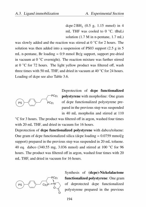
A.3. Ligand immobilization A. Experimental Section
dcpe⋅2 BH3 (0.5 g, 1.15 mmol) in 4mL THF was cooled to 0 ○C. tBuLisolution (1.7 M in n-pentane, 1.7 mL)
was slowly added and the reaction was stirred at 0 ○C for 2 hours. Thesolution was then added into a suspension of PS03 support (2.5 g in 5mL n-pentane, Br loading = 0.9 mmol Br/g support, support pre-driedin vacuum at 0 ○C overnight). The reaction mixture was further stirredat 0 ○C for 72 hours. The light yellow product was filtered off, washthree times with 50 mL THF, and dried in vacuum at 40 ○C for 24 hours.Loading of dcpe see also Table 3.6.
PS PCy2
PCy2
Deprotection of dcpe functionalizedpolystyrene with morpholine: One gramof dcpe functionalized polystyrene pre-pared in the previous step was suspendedin 40 mL morpholin and stirred at 110
○C for 3 hours. The product was filtered off in argon, washed four timeswith 20 mL THF, and dried in vacuum for 16 hours.Deprotection of dcpe functionalized polystyrene with dabco/toluene:One gram of dcpe functionalized silica (dcpe loading = 0.0759 mmol/gsupport) prepared in the previous step was suspended in 20 mL toluene.40 eq. dabco (340.55 mg, 3.036 mmol) and stirred at 100 ○C for 96hours. The product was filtered off in argon, washed four times with 20mL THF, and dried in vacuum for 16 hours.
PS Cy2P
PCy2
NiO
O
Synthesis of (dcpe)-Nickelalactonefunctionalized polystyrene: One gramof deprotected dcpe functionalizedpolystyrene prepared in the previous
194
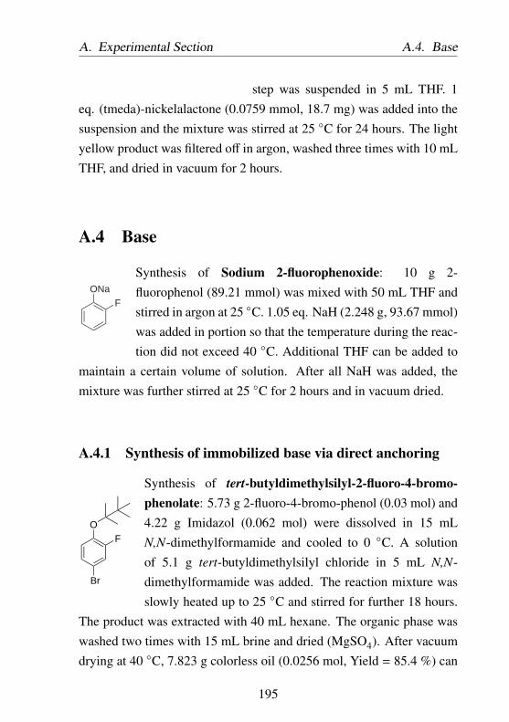
A. Experimental Section A.4. Base
step was suspended in 5 mL THF. 1eq. (tmeda)-nickelalactone (0.0759 mmol, 18.7 mg) was added into thesuspension and the mixture was stirred at 25 ○C for 24 hours. The lightyellow product was filtered off in argon, washed three times with 10 mLTHF, and dried in vacuum for 2 hours.
A.4 Base
FONa
Synthesis of Sodium 2-fluorophenoxide: 10 g 2-fluorophenol (89.21 mmol) was mixed with 50 mL THF andstirred in argon at 25 ○C. 1.05 eq. NaH (2.248 g, 93.67 mmol)was added in portion so that the temperature during the reac-tion did not exceed 40 ○C. Additional THF can be added to
maintain a certain volume of solution. After all NaH was added, themixture was further stirred at 25 ○C for 2 hours and in vacuum dried.
A.4.1 Synthesis of immobilized base via direct anchoring
OF
Br
Synthesis of tert-butyldimethylsilyl-2-fluoro-4-bromo-phenolate: 5.73 g 2-fluoro-4-bromo-phenol (0.03 mol) and4.22 g Imidazol (0.062 mol) were dissolved in 15 mLN,N-dimethylformamide and cooled to 0 ○C. A solutionof 5.1 g tert-butyldimethylsilyl chloride in 5 mL N,N-dimethylformamide was added. The reaction mixture wasslowly heated up to 25 ○C and stirred for further 18 hours.
The product was extracted with 40 mL hexane. The organic phase waswashed two times with 15 mL brine and dried (MgSO4). After vacuumdrying at 40 ○C, 7.823 g colorless oil (0.0256 mol, Yield = 85.4 %) can
195

A.4. Base A. Experimental Section
be isolated.
PS
OTBDMS
F
Preparation of polystyrene immobi-lized tert-butyldimethylsilyl-2-floro-phenolate via direct anchoring: 87.6mg Magnesium turnings was suspendedin 5 mL THF. A small piece of iodinewas added at 0 ○C and the suspension
was stirred for 10 minutes. A solution of 1 g tert-butyldimethylsilyl-2-fluoro-4-bromo-phenolate (3.276 mmol) in 5 mL THF was added andthe reaction mixture was stirred at 50 ○C for 60 minutes. The Grignardreagent was cooled to 0 ○C. 2.34 g PS05 (Br loading: 2.8 mmol/g)was added to the Grignard reagent and the reaction mixture was furtherstirred at 0 ○C for 20 hours. The solid was filtered off, washed threetimes with 30 mL THF, and dried in vacuum.
PS
OH
F
Deprotection of polystyrene immobilizedtert-butyldimethylsilyl-2-florophenolate B5with TBAF: 1 g of immobilized tert-butyldimethylsilyl-2-florophenolate was sus-pended 5 mL THF. A solution of 1 M TBAFin THF (403 mg in 1.5 mL THF) was added
and the reaction mixture was stirred at 0 ○C for 30 minutes. The reactionmixture was slowly heated up to 25 ○C and diluted with 10 mL ethylacetate. 10 mL 1 M aqueous HCl solution was added and the reactionmixture was stirred for 30 minutes. The solid was filtered off, washedfour times with 10 mL ethyl acetate, and dried in vacuum. Elementalanalysis B5.1: 61.7 wt% C, 5.9 wt% H, 0.7 wt% F. Elemental analysis
196

A. Experimental Section A.4. Base
B5.2: 63.9 wt% C, 6.0 wt% H, 0.35 wt% F.
A.4.2 Synthesis of immobilized base via copolymerization
FOH
Synthesis of 2-fluoro-4-vinyl-phenol [277]: 3.82 g 4-bromo-2-fluorophenol (20 mmol) was mixed with 20mL THF. 1 mol% [1,1-bis(diphenylphosphino)ferrocene]-dichloropalladium(II) (PdCl2dppf) (146.2 mg, 0.2 mmol)was added into the solution and the mixture was stirred at-78 ○C for 10 min. 2 eq. of vinylmagnesiumbromide solution
(0.7 M in THF, 57.1 mL) was slowly added and the reaction mixture wasfurther stirred at -78 ○C for 10 min. The mixture was slowly warmed to25 ○C and refluxed for two hours. After cooling to room temperature,the reaction was slowly quenched with 40 mL 1 M HCl solution. Themixture was further stirred at 25 ○C for 30 min. The product wasextracted from diethylether and dried followed with recrystallizationfrom hexane/diethylether to give 1.86 g yellow oil (13.45 mmol, yield =
67%). 200.15-MHz 1H NMR (CDCl3): δ 5.0 - 5.05 (1H, doublet), 5.43- 5.52 (1H, doublet), 6.4 - 6.55 (1H, doublet of doublets), 6.6 - 7.2 (3H,multiplet), 8.12 (1H, singlet).
OHF
nm
Copolymerization of 2-fluoro-4-vinyl-phenoland styrene B6: 729.05 mg styrene (7 mmol),414.42 mg 2-fluoro-4-vinyl-phenol (3 mmol),2.6 mg 1,4-divinylbenzene (0.02 mmol), and0.05 mmol 2,2-Azobis(2-methylpropionitrile)solution in toluene (0.25 mL, 0.2 M) weremixed with 1 mL chlorobenzene. The mixture
was heated up to 60 ○C and stirred for 12 hours in Argon. The mixture
197

A.4. Base A. Experimental Section
was cooled to 25 ○C and the polymer was precipitated into methanol.The precipitated methanol was dissolved in THF and reprecipitated intomethanol. The purification procedure was repeated twice and the solidpolymer product was dried in vacuum to give 300 mg light yellow poly-mer. Elemental analysis: 85.7 wt% C, 7.2 wt% H, 3.2 wt% F.
PS ONa
F
Preparation of immobilized sodium 2-fluoro-phenolate: 1g of immobilized 2-fluorophenolprepared in the previous step (OH loading:1.6844 mmol/g) was suspended in 10 mL THFin argon at 25 ○C. 40.42 mg NaH (1.684 mmol)
was slowly added into the suspension mixture and stirred for further 15minutes. The resulting immobilized sodium 2-fluoro-phenolate can bedirectly used in the catalytic reaction.
Recycling of immobilized phenol with aqueous HCl solution: spentbase after the acrylate catalytic reaction was suspended in 1 M aqueousHCl solution and stirred for 30 minutes at 25 ○C to liberate all hydroxylgroups. The solid was filtrated and washed with ethanol to remove anyphysisorbed and chemisorbed nickel complex species. The regenera-tion procedure was repeated five times until the color of spent base issimilar to fresh immobilized base (pale yellow beads). The regeneratedimmobilized base was dried at 50 ○C in vacuum overnight to removeall volatile impurities to give immobilized phenol base. The recycledbase can finally be reactivated with the same procedure as immobilizedsodium 2-fluoro-phenolate described above.
198
A. Experimental Section A.4. Base
Recycling of immobilized phenol with aqueous NaOH solution: spentbase after the acrylate catalytic reaction was suspended in 1 M aque-ous NaOH solution and stirred for 30 minutes at 25 ○C to liberate allhydroxyl groups. The solid was filtrated and washed with ethanol toremove any physisorbed and chemisorbed nickel complex species. Theregeneration procedure was repeated five times until the color of spentbase is similar to fresh immobilized base (pale yellow beads). At thefinal step, the immobilized base was suspended again in 1 M aqueousNaOH solution and subsequently dried at 50 ○C in vacuum overnightto remove all volatile impurities to give immobilized sodium phenolatebase.
199

A.4. Base A. Experimental Section
200
Appendix B
List of Chemicals
201

B. List of Chemicals
Table B.1: List of Solvents.
Name Specification Supplier
1,4-Dioxane 99.8 %, H2O < 0.003 % Sigma Aldrich
Chlorobenzene 99.8 %, H2O < 0.005 % Sigma Aldrich
D2O 99.8 atom % D Sigma Aldrich
Dichloromethane99.8 %, H2O < 0.001 % with
50-150 ppm amylene asstabilizer
Sigma Aldrich
Diethyl ether 99.9 %, H2O < 0.03 % Sigma Aldrich
Ethanol 99.8 %, absolute Sigma Aldrich
Ethyl Acetate 99.8 % Sigma Aldrich
Hexane 95 %, H2O < 0.001 % Sigma Aldrich
Methanol 99.8 %, H2O < 0.002 % Sigma Aldrich
N,N-dimethylformamide
99.8 %, H2O < 0.005 % Sigma Aldrich
Pentane 99 %, H2O < 0.002 % Sigma Aldrich
Tetrahydrofuran
99.5 %, absolute overmolecular sieve with 0.025 %
2,6-di-tert-butyl-4-methylphenol as stabilizer,
H2O < 0.005 %
Sigma Aldrich
Toluene 99.8 %, H2O < 0.001 % Sigma Aldrich
202

B. List of Chemicals
Table B.2: Silica supports used for functionalization.
Properties Cariact Q-20C SBA-15 [270]
Average pore diameter [nm] 20 6
Specific surface area [m2/g] 140 1164
Pore volume [mL/g] 0.8 1.25
-OH content [mmol/g] no data 2.8
Supplier Fuji Silysia University of
Chemical Stuttgart
PSBr
SiO2 O SiO
OBr
OTMS
OTMS
PSO
Cl
PSO
Br
PSCl
PS01
PS02
PS03
PS04
S1: Br loading = 0.5632 mmol/gS2: Br loading = 1.1889 mmol/gBrSBA-15: Br loading = 0.6007 mmol/g
Cl loading = 6.05 mmol/g
Cl loading = 1.27 mmol/g Br loading = 0.91 mmol/g
Br loading = 0.9 mmol/g
PSBr
PS05
Br loading = 2.8 mmol/g
Figure B-1: PS01 - PS05 were purchased from Sigma Aldrich. S1 and S2supports were prepared from Cariact Q-20C. BrSBA-15 wasprepared from SBA-15. For preparation method see alsoAppendix A.3.2.
203

B. List of Chemicals
OHPS
PS
N
PS
NN Cl
PSOH
B1
B2
B3
B4
B1.1: loading = 1 mmol/g, Sigma AldrichB1.2: loading = 3.5 mmol/g2% DVB, Alfa Aesar
loading = 2.9 mmol/g2% DVB, Sigma Aldrich
loading = 1.25 mmol/g1% DVB, Sigma Aldrich
loading = 2 mmol/g1% DVB, Sigma Aldrich
Figure B-2: Commercial immobilized base.
204
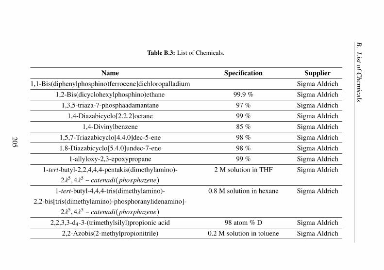
B.
ListofC
hemicals
Table B.3: List of Chemicals.
Name Specification Supplier1,1-Bis(diphenylphosphino)ferrocene]dichloropalladium Sigma Aldrich
1,2-Bis(dicyclohexylphosphino)ethane 99.9 % Sigma Aldrich
1,3,5-triaza-7-phosphaadamantane 97 % Sigma Aldrich
1,4-Diazabicyclo[2.2.2]octane 99 % Sigma Aldrich
1,4-Divinylbenzene 85 % Sigma Aldrich
1,5,7-Triazabicyclo[4.4.0]dec-5-ene 98 % Sigma Aldrich
1,8-Diazabicyclo[5.4.0]undec-7-ene 98 % Sigma Aldrich
1-allyloxy-2,3-epoxypropane 99 % Sigma Aldrich
1-tert-butyl-2,2,4,4,4-pentakis(dimethylamino)- 2 M solution in THF Sigma Aldrich2λ5,4λ5
− catenadi(phosphazene)
1-tert-butyl-4,4,4-tris(dimethylamino)- 0.8 M solution in hexane Sigma Aldrich2,2-bis[tris(dimethylamino)-phosphoranylidenamino]-
2λ5,4λ5− catenadi(phosphazene)
2,2,3,3-d4-3-(trimethylsilyl)propionic acid 98 atom % D Sigma Aldrich
2,2-Azobis(2-methylpropionitrile) 0.2 M solution in toluene Sigma Aldrich
205

B.
ListofC
hemicals
2-fluorophenol 98 % Sigma Aldrich
2-tert-Butylimino-2-diethylamino-1,3- 98 % Sigma Aldrichdimethylperhydro-1,3,2-diazaphosphorine
(3-Bromopropyl)trimethoxysilane 97 % Sigma Aldrich
4-(Dimethylamino)pyridine 99 % Sigma Aldrich
Bis(1,5-cyclooctadiene)nickel(0) 99.9 % Acros
Borane dimethylsulfide complex 2 M solution in THF Sigma Aldrich
Calcium hydride 99 % Sigma Aldrich
Cesium carbonate 99.9 % Sigma Aldrich
Chlorodiphenylphosphine 96 % Sigma Aldrich
Chloroplatinic acid hydrate 99.9 % Sigma Aldrich
Dicyclohexylphosphine 97 % Sigma Aldrich
Diethylamine 99.5 % Sigma Aldrich
Hydrochloric acid, 37 %, Sigma Aldrich
Imidazole 99 % Sigma Aldrich
Iodine 99.9 % Sigma Aldrich
Lithium carbonate 99 % Sigma Aldrich
Lithium chloride 99 % Sigma Aldrich
206

B.
ListofC
hemicals
Lithium hydride 95 % Sigma Aldrich
Magnesium 99.95 %, turnings Sigma Aldrich
Magnesium sulfate 99.5 %, anhydrous Sigma Aldrich
Morpholin 99.5 % Sigma Aldrich
N-chlorosuccinimide 98 % Sigma Aldrich
N,N-diethylaniline 99.5 % Sigma Aldrich
N,N-dimethylaniline 99.5 % Sigma Aldrich
N,N,N,N-Tetramethylethylenediamine 99.5 % Sigma Aldrich
Potassium hydride 30 wt% in mineral oil Sigma Aldrich
Platinum(0)-1,3-divinyl-1,1,3,3-tetramethyldisiloxane 0.1 M in poly(dimethylsiloxane) Sigma Aldrich
(S,S)-(-)-1,2-Bis(t-butylmethylphosphino)benzene 99.9 % ABCR
Sodium acrylate 97 % Sigma Aldrich
Sodium bis(trimethylsilyl)amide 1 M solution in THF Sigma Aldrich
Sodium carbonate 99 % Sigma Aldrich
Sodium hydride 95 % Sigma Aldrich
Sodium hydroxide 98 % Sigma Aldrich
Sodium tetrakis[3,5-bis(trifluoromethyl)phenyl]borate Sigma Aldrich
Succinic anhydride 99 % Sigma Aldrich
207

B.
ListofC
hemicals
tert-Butyldimethylsilyl chloride 97 % Sigma Aldrich
tert-Butyllithium 1.7 M solution in pentane Sigma Aldrich
tert-butyl-tris(dimethylamino)phosphorane 97 % Sigma Aldrich
Tetrabutylammonium fluoride hydrate 98 % Sigma Aldrich
Tetrafluoroboric acid 50 % Sigma Aldrich
Tetramethylammonium iodide 99 % Alfa Aesar
Triethylamine 99 % Sigma Aldrich
Triocthylamine 98 % Sigma Aldrich
Trimethylchlorosilane 99 % Sigma Aldrich
Trimethoxysilane 95 % Sigma Aldrich
Vinylmagnesium bromide 0.7 M solution in THF Acros
208

Bibliography
[1] M. Aresta, A. Dibenedetto, Key Issues in Carbon Dioxide Uti-lization as a Building Block for Molecular Organic Compoundsin the Chemical Industry, chapter 5, pp. 54–70.
[2] T. Ohara, T. Sato, N. Shimizu, G. Prescher, H. Schwind,O. Weiberg, K. Marten, H. Greim, Acrylic Acid and Derivativesin Ullmann’s Encyclopedia of Industrial Chemistry, Wiley-VCHVerlag GmbH & Co. KGaA, 2000.
[3] J. Glauser, M. Blagoev, T. Kumamoto, Acrylic Acid, AcrylateEsters and Superabsorbent Polymers, SRI Consulting, 2011.
[4] M. Frank, Superabsorbents in Ullmann’s Encyclopedia of Indus-trial Chemistry, Wiley-VCH Verlag GmbH & Co. KGaA, 2000.
[5] F. L. Buchholz, Superabsorbent Polymers in Encyclopedia ofPolymer Science and Technology, John Wiley & Sons, Inc., 2002.
[6] K. Weissermel, H.-J. Arpe, Propene Conversion Products in In-dustrial Organic Chemistry, Wiley-VCH Verlag GmbH, 2007,pp. 265–310.
[7] W. Reppe, Neue Entwicklungen auf dem Gebiet der Chemie desAcetylen und Kohlenoxyds, Springer, 1949.
[8] W. Bertleff, M. Roeper, X. Sava, Carbonylation, Wiley-VCHVerlag GmbH & Co. KGaA, 2000.
209

BIBLIOGRAPHY BIBLIOGRAPHY
[9] S. Masato, S. Takeshi, K. Chiyoji, Production of carbonate com-pound, 1999.
[10] M. Tanimoto, N. Hakozaki, Process for producing acroleinand/or acrylic acid, 2013, US Patent 8,415,498. https://www.google.com/patents/US8415498.
[11] N. Fukumoto, T. Nishiguchi, Catalyst for producing of acrylicacid, method for producing acrylic acid using the catalyst andmethod for producing water-absorbent resin using the acrylicacid, 2013, US Patent 8,507,626. https://www.google.com/patents/US8507626.
[12] J. Macht, A. Karpov, C. Dobner, F. Rosowski, U. Hammon,K. Mueller-Engel, Mo-, bi- and fe-comprising multimetal ox-ide compositions, 2013, US Patent App. 13/546,546. https://www.google.com/patents/US20130023699.
[13] K. Gehrmann, A. Hauser, W. Lork, K. Sennewald, K. Steil, Pro-cess for isolating acrylic acid from the reaction gases obtainedby the oxidation of propylene or a acrolein, 1973, US Patent3,717,675. https://www.google.com/patents/US3717675.
[14] G. Fisher, T. Horlenko, Acrylic acid purification, 1979, US Patent4,156,633. https://www.google.com/patents/US4156633.
[15] C. Boswell. Acrylate prices drive new manufacturing routes. ICISChemical Business 2011.
[16] A. Lundgren, T. Hjertberg, Ethylene from Renewable Resourcesin Surfactants from Renewable Resources, M. Kjellin, I. Johans-son (Eds.), John Wiley & Sons, Ltd, 2010, pp. 109–126.
[17] M. Aresta, Carbon Dioxide: Utilization Options to Reduce itsAccumulation in the Atmosphere, Wiley-VCH Verlag GmbH &Co. KGaA, 2010, pp. 1–13.
[18] M. R. Kember, A. Buchard, C. K. Williams. Catalysts forCO2/epoxide copolymerisation. Chem. Commun. 2011, 47, 141–163.
210

BIBLIOGRAPHY BIBLIOGRAPHY
[19] P. Tans, R. Keeling, Trends in Atmospheric Carbon Dioxide,2014. http://www.esrl.noaa.gov/gmd/ccgg/trends/.
[20] M. T. Ho, G. W. Allinson, D. E. Wiley. Reducing the Cost ofCO2 Capture from Flue Gases Using Membrane Technology.Industrial & Engineering Chemistry Research 2008, 47, 1562–1568.
[21] M. T. Ho, G. W. Allinson, D. E. Wiley. Reducing the Cost ofCO2 Capture from Flue Gases Using Pressure Swing Adsorption.Industrial & Engineering Chemistry Research 2008, 47, 4883–4890.
[22] M. Tuinier, M. van Sint Annaland, G. Kramer, J. Kuipers. Cryo-genic capture using dynamically operated packed beds. Chemi-cal Engineering Science 2010, 65, 114 – 119, 20th InternationalSymposium in Chemical Reaction Engineering—Green Chem-ical Reaction Engineering for a Sustainable Future.
[23] D. Singh, E. Croiset, P. Douglas, M. Douglas. Techno-economicstudy of {CO2} capture from an existing coal-fired power plant:{MEA} scrubbing vs. O2/CO2 recycle combustion. Energy Con-version and Management 2003, 44, 3073 – 3091.
[24] Z. Liu, C. A. Grande, P. Li, J. Yu, A. E. Rodrigues. Multi-bedVacuum Pressure Swing Adsorption for carbon dioxide capturefrom flue gas. Separation and Purification Technology 2011, 81,307 – 317.
[25] E. S. Kikkinides, R. T. Yang, S. H. Cho. Concentration and recov-ery of carbon dioxide from flue gas by pressure swing adsorption.Industrial & Engineering Chemistry Research 1993, 32, 2714–2720.
[26] B.-K. Na, H. Lee, K.-K. Koo, H. K. Song. Effect of Rinse and Re-cycle Methods on the Pressure Swing Adsorption Process To Re-cover CO2 from Power Plant Flue Gas Using Activated Carbon.Industrial & Engineering Chemistry Research 2002, 41, 5498–5503.
211

BIBLIOGRAPHY BIBLIOGRAPHY
[27] K. T. Chue, J. N. Kim, Y. J. Yoo, S. H. Cho, R. T. Yang. Com-parison of Activated Carbon and Zeolite 13X for CO2 Recoveryfrom Flue Gas by Pressure Swing Adsorption. Industrial & Engi-neering Chemistry Research 1995, 34, 591–598.
[28] J.-H. Park, H.-T. Beum, J.-N. Kim, S.-H. Cho. Numerical Anal-ysis on the Power Consumption of the PSA Process for Recov-ering CO2 from Flue Gas. Industrial & Engineering ChemistryResearch 2002, 41, 4122–4131.
[29] A. D. Ebner, J. A. Ritter. State-of-the-art Adsorption and Mem-brane Separation Processes for Carbon Dioxide Production fromCarbon Dioxide Emitting Industries. Separation Science andTechnology 2009, 44, 1273–1421.
[30] D. Ko, R. Siriwardane, L. T. Biegler. Optimization of a Pressure-Swing Adsorption Process Using Zeolite 13X for CO2 Seques-tration. Industrial & Engineering Chemistry Research 2003, 42,339–348.
[31] P. Xiao, J. Zhang, P. Webley, G. Li, R. Singh, R. Todd. Capture ofCO2 from flue gas streams with zeolite 13X byvacuum-pressureswing adsorption. Adsorption 2008, 14, 575–582.
[32] J. A. McIntyre, A. D. Ebner, J. A. Ritter. Experimental Studyof a Dual Reflux Enriching Pressure Swing Adsorption Processfor Concentrating Dilute Feed Streams. Industrial & EngineeringChemistry Research 2010, 49, 1848–1858.
[33] M. Whysall, L. Wagemans, Very large-scale pressure swing ad-sorption processes, 2001, US Patent 6,210,466. http://www.google.nl/patents/US6210466.
[34] J. Chase, M.W., NIST-JANAF Themochemical Tables, FourthEdition, Vol. 9 of J. Phys. Chem. Ref. Data, Monograph, 1998.
[35] T. Sakakura, J.-C. Choi, H. Yasuda. Transformation of CarbonDioxide. Chemical Reviews 2007, 107, 2365–2387.
212

BIBLIOGRAPHY BIBLIOGRAPHY
[36] M. Aresta, A. Dibenedetto. Utilisation of CO2 as a chemical feed-stock: opportunities and challenges. Dalton Trans. 2007, 2975–2992.
[37] J. H. Meessen, Urea, Wiley-VCH Verlag GmbH & Co. KGaA,2000.
[38] E. Fiedler, G. Grossmann, D. B. Kersebohm, G. Weiss, C. Witte,Methanol, Wiley-VCH Verlag GmbH & Co. KGaA, 2000.
[39] T. Askgaard, J. Norskov, C. Ovesen, P. Stoltze. A Kinetic Modelof Methanol Synthesis. Journal of Catalysis 1995, 156, 229 –242.
[40] W.-L. Wong, K.-C. Cheung, P.-H. Chan, Z.-Y. Zhou, K.-H. Lee,K.-Y. Wong. A tricarbonyl rhenium(I) complex with a pendantpyrrolidinium moiety as a robust and recyclable catalyst forchemical fixation of carbon dioxide in ionic liquid. Chem. Com-mun. 2007, 2175–2177.
[41] J. Wang, J. Wu, N. Tang. Synthesis, characterization of a newbicobalt complex [Co2L2(C2H5OH)2Cl2] and application incyclic carbonate synthesis. Inorganic Chemistry Communica-tions 2007, 10, 1493 – 1495.
[42] J. Melendez, M. North, R. Pasquale. Synthesis of Cyclic Carbon-ates from Atmospheric Pressure Carbon Dioxide Using Excep-tionally Active Aluminium(salen) Complexes as Catalysts. Euro-pean Journal of Inorganic Chemistry 2007, 2007, 3323–3326.
[43] X.-Y. Dou, J.-Q. Wang, Y. Du, E. Wang, L.-N. He. GuanidiniumSalt Functionalized PEG: An Effective and Recyclable Homoge-neous Catalyst for the Synthesis of Cyclic Carbonates from CO2and Epoxides under Solvent-Free Conditions. Synlett 2007, 2007,3058–3062.
[44] E.-H. Lee, J.-Y. Ahn, M. M. Dharman, D.-W. Park, S.-W. Park,I. Kim. Synthesis of cyclic carbonate from vinyl cyclohexene
213

BIBLIOGRAPHY BIBLIOGRAPHY
oxide and {CO2} using ionic liquids as catalysts. Catalysis Today2008, 131, 130 – 134, Recent advances in catalysis - selectedpapers from {APCAT} 4 (Singapore, 6-8 December 2006).
[45] T. Sakai, Y. Tsutsumi, T. Ema. Highly active and robust organic-inorganic hybrid catalyst for the synthesis of cyclic carbonatesfrom carbon dioxide and epoxides. Green Chem. 2008, 10, 337–341.
[46] B. Fan, J. Zhang, R. Li, W. Fan. InSitu Preparation of FunctionalHeterogeneous Organotin Catalyst Tethered on SBA-15. Cataly-sis Letters 2008, 121, 297–302.
[47] Y. Du, L.-N. He, D.-L. Kong. Magnesium-catalyzed synthesisof organic carbonate from 1,2-diol/alcohol and carbon dioxide.Catalysis Communications 2008, 9, 1754 – 1758.
[48] F. Jutz, J.-D. Grunwaldt, A. Baiker. Mn(III)(salen)-catalyzed syn-thesis of cyclic organic carbonates from propylene and styreneoxide in supercritical {CO2}. Journal of Molecular Catalysis A:Chemical 2008, 279, 94 – 103.
[49] T. Sakakura, K. Kohno. The synthesis of organic carbonates fromcarbon dioxide. Chem. Commun. 2009, 1312–1330.
[50] H. Kolbe. Ueber Synthese der Salicylsäure. Justus Liebigs An-nalen der Chemie 1860, 113, 125–127.
[51] R. Schmitt. Beitrag zur Kenntniss der Kolbe’schen SalicylsäureSynthese. Journal für Praktische Chemie 1885, 31, 397–411.
[52] A. S. Lindsey, H. Jeskey. The Kolbe-Schmitt Reaction. ChemicalReviews 1957, 57, 583–620.
[53] O. Boullard, H. Leblanc, B. Besson, Salicylic Acid, Wiley-VCHVerlag GmbH & Co. KGaA, 2000.
[54] C. Song, W. Pan. Tri-reforming of methane: a novel conceptfor catalytic production of industrially useful synthesis gas withdesired H2/CO ratios. Catalysis Today 2004, 98, 463 – 484.
214

BIBLIOGRAPHY BIBLIOGRAPHY
[55] A. Slagtern, U. Olsbye, R. Blom, I. M. Dahl, H. Fjellvag. In situ{XRD} characterization of LaNiAlO model catalysts for {CO2}reforming of methane. Applied Catalysis A: General 1996, 145,375 – 388.
[56] G. Valderrama, M. R. Goldwasser, C. U. de Navarro, J. M.Tatibouët, J. Barrault, C. Batiot-Dupeyrat, F. Martinez. Dry re-forming of methane over Ni perovskite type oxides. CatalysisToday 2005, 107–108, 785 – 791, Selected Contributions ofthe {XIX} Ibero American Catalysis Symposium Selected Con-tributions of the {XIX} Ibero American Catalysis Symposium.
[57] Y. Hu, E. Ruckenstein. An optimum NiO content in the CO2reforming of CH4 with NiO/MgO solid solution catalysts. Catal-ysis Letters 1996, 36, 145–149.
[58] S. Tsang, J. Claridge, M. Green. Recent advances in the conver-sion of methane to synthesis gas. Catalysis Today 1995, 23, 3 –15, Recent Advances in {C1} Chemistry.
[59] F. Pompeo, N. N. Nichio, M. M. Souza, D. V. Cesar, O. A.Ferretti, M. Schmal. Study of Ni and Pt catalysts supported ona-Al2O3 and ZrO2 applied in methane reforming with {CO2}.Applied Catalysis A: General 2007, 316, 175 – 183.
[60] C. Gigola, M. Moreno, I. Costilla, M. Sanchez. Characterizationof Pd-CeOx interaction on a-Al2O3 support. Applied Surface Sci-ence 2007, 254, 325 – 329, Proceedings of the 13th InternationalConference on Solid Films and Surfaces {ICSFS} 13.
[61] J. F. Munera, S. Irusta, L. M. Cornaglia, E. A. Lombardo, D. V.Cesar, M. Schmal. Kinetics and reaction pathway of the {CO2}reforming of methane on Rh supported on lanthanum-based solid.Journal of Catalysis 2007, 245, 25 – 34.
[62] K. Nagaoka, K. Seshan, K.-i. Aika, J. A Lercher. Carbon Deposi-tion during Carbon Dioxide Reforming of Methane-Comparisonbetween Pt/Al2O3 and Pt/ZrO2. Journal of Catalysis 2001, 197,34 – 42.
215

BIBLIOGRAPHY BIBLIOGRAPHY
[63] M. M. Barroso Quiroga, A. E. Castro Luna. Kinetic Analysis ofRate Data for Dry Reforming of Methane. Industrial & Engineer-ing Chemistry Research 2007, 46, 5265–5270.
[64] M. C. J. Bradford, M. A. Vannice. CO2 Reforming of CH4.Catalysis Reviews 1999, 41, 1–42.
[65] J. R. Rostrup-Nielsen, J. Sehested, Hydrogen and synthesis gasby steam- and {C02} reforming, Vol. 47 of Advances in Catalysis,Academic Press, 2002, pp. 65 – 139.
[66] K. Klier, Methanol Synthesis, Vol. 31 of Advances in Catalysis,H. P. D.D. Eley, P. B. Weisz (Eds.), Academic Press, 1982, pp.243 – 313.
[67] J. Bart, R. Sneeden. Copper-zinc oxide-alumina methanol cata-lysts revisited. Catalysis Today 1987, 2, 1 – 124.
[68] M. Bowker, R. Hadden, H. Houghton, J. Hyland, K. Waugh. Themechanism of methanol synthesis on copper/zinc oxide/aluminacatalysts. Journal of Catalysis 1988, 109, 263 – 273.
[69] M. A. McNeil, C. J. Schack, R. G. Rinker. Methanol synthe-sis from hydrogen, carbon monoxide and carbon dioxide over aCuO/ZnO/Al2O3 catalyst: II. Development of a phenomenologi-cal rate expression. Applied Catalysis 1989, 50, 265 – 285.
[70] C. Song, Introduction to Hydrogen and Syngas Production andPurification Technologies, John Wiley & Sons, Inc., 2009, pp.1–13.
[71] K. Weissermel, H.-J. Arpe, Basic Products of Industrial Synthe-ses in Industrial Organic Chemistry, Wiley-VCH Verlag GmbH,2007, pp. 13–58.
[72] K. H. Büchel, H.-H. Moretto, P. Woditsch, Primary InorganicMaterials in Industrial Inorganic Chemistry, Wiley-VCH VerlagGmbH, 2007, pp. 1–185.
216

BIBLIOGRAPHY BIBLIOGRAPHY
[73] N. M. Laurendeau. Heterogeneous kinetics of coal char gasifica-tion and combustion. Progress in Energy and Combustion Sci-ence 1978, 4, 221 – 270.
[74] X. Li, J. Grace, C. Lim, A. Watkinson, H. Chen, J. Kim. Biomassgasification in a circulating fluidized bed. Biomass and Bioenergy2004, 26, 171 – 193.
[75] D. Möst, H. Perlwitz. Prospects of gas supply until 2020 in Eu-rope and its relevance for the power sector in the context of emis-sion trading. Energy 2009, 34, 1510 – 1522, 11th Conferenceon Process Integration, Modelling and Optimisation for EnergySaving and Pollution Reduction.
[76] H.-H. Rogner. An Assessment of World Hydrocarbon Resources.Annual Review of Energy and the Environment 1997, 22, 217–262.
[77] R. F. Aguilera. The future of the European natural gas market: Aquantitative assessment. Energy 2010, 35, 3332 – 3339.
[78] K. Liu, G. D. Deluga, A. Bitsch-Larsen, L. D. Schmidt, L. Zhang,Catalytic Partial Oxidation and Autothermal Reforming, JohnWiley & Sons, Inc., 2009, pp. 127–155.
[79] R. Reimert, F. Marschner, H.-J. Renner, W. Boll, E. Supp,M. Brejc, W. Liebner, G. Schaub, Gas Production, 2. Processes,Wiley-VCH Verlag GmbH & Co. KGaA, 2000.
[80] W. Boll, G. Hochgesand, C. Higman, E. Supp, P. Kalteier, W.-D.Müller, M. Kriebel, H. Schlichting, H. Tanz, Gas Production, 3.Gas Treating, Wiley-VCH Verlag GmbH & Co. KGaA, 2000.
[81] I. Wender. Reactions of synthesis gas. Fuel Processing Technol-ogy 1996, 48, 189 – 297, Reactions of synthesis gas.
[82] A. P. E. York, T.-c. Xiao, M. L. H. Green, J. B. Claridge. MethaneOxyforming for Synthesis Gas Production. Catalysis Reviews2007, 49, 511–560.
217

BIBLIOGRAPHY BIBLIOGRAPHY
[83] V. Subramani, P. Sharma, L. Zhang, K. Liu, Catalytic Steam Re-forming Technology for the Production of Hydrogen and Syngas,John Wiley & Sons, Inc., 2009, pp. 14–126.
[84] K. Liu, Z. Cui, T. H. Fletcher, Coal Gasification, John Wiley &Sons, Inc., 2009, pp. 156–218.
[85] X. D. Peng, A. W. Wang, B. A. Toseland, P. J. A. Tijm. Single-Step Syngas-to-Dimethyl Ether Processes for Optimal Productiv-ity, Minimal Emissions, and Natural Gas-Derived Syngas. Indus-trial & Engineering Chemistry Research 1999, 38, 4381–4388.
[86] D. H. Gibson. Carbon dioxide coordination chemistry: metalcomplexes and surface-bound species. What relationships? Co-ordination Chemistry Reviews 1999, 185-186, 335 – 355.
[87] I. Tommasi, F. Sorrentino. Utilisation of 1,3-dialkylimidazolium-2-carboxylates as CO2-carriers in the presence of Na+ and K+:application in the synthesis of carboxylates, monomethylcarbon-ate anions and halogen-free ionic liquids. Tetrahedron Letters2005, 46, 2141 – 2145.
[88] H. Hoberg, Y. Peres, C. Krüger, Y.-H. Tsay. A 1-Oxa-2-nickela-5-cyclopentanone from Ethene and Carbon Dioxide: Preparation,Structure, and Reactivity. Angew. Chem., Int. Ed. Engl. 1987, 26,771–773.
[89] H. Hoberg, K. Sümmermann, A. Milchereit. CC-Verknüpfungvon Alkenen mit Isocyanaten an Ni0-Komplexen - eine neue Syn-these von Acrylsäureamiden. Angew. Chem. 1985, 97, 321–321.
[90] D. Walther, E. Dinjus, J. Sieler, L. Andersen, O. Lindqvist.Aktivierung von kohlendioxid an Übergangsmetallzentren:Metallaringschluss mit dicyclopentadien am elektronenreichennickel(0)-komplexrumpf als topo- und stereoselektive reaktion.Journal of Organometallic Chemistry 1984, 276, 99 – 107.
218

BIBLIOGRAPHY BIBLIOGRAPHY
[91] H. Hoberg, D. Schaefer. Nickel(0)-induzierte C - C-verknüpfungzwischen kohlendioxid und ethylen sowie mono- oder di-substituierten alkenen. J. Organomet. Chem. 1983, 251, C51 –C53.
[92] S. A. Cohen, J. E. Bercaw. Titanacycles derived form reductivecoupling of nitriles, alkynes, acetaldehyde, and carbon dioxidewith bis(pentamethylcyclopentadienyl)(ethylene)titanium(II).Organometallics 1985, 4, 1006–1014.
[93] H. Hoberg, K. Jenni, K. Angermund, C. Krüger. CC-Linkages ofEthene with CO2 on an Iron(0) Complex-Synthesis and CrystalStructure Analysis of [(PEt3)2Fe(C2H4)2]. Angewandte ChemieInternational Edition in English 1987, 26, 153–155.
[94] R. Alvarez, E. Carmona, D. J. Cole-Hamilton, A. Galindo,E. Gutierrez-Puebla, A. Monge, M. L. Poveda, C. Ruiz. Forma-tion of acrylic acid derivatives from the reaction of carbon dioxidewith ethylene complexes of molybdenum and tungsten. Journalof the American Chemical Society 1985, 107, 5529–5531.
[95] M. Aresta, E. Quaranta. Synthesis, characterization and reactiv-ity of [Rh(bpy)(C2H4)Cl]. A study on the reaction with {C1}molecules (CH2O, CO2) and NaBPh4. Journal of Organometal-lic Chemistry 1993, 463, 215 – 221.
[96] Y. Inoue, Y. Itoh, H. Kazama, H. Hashimoto. Reaction of Dialkyl-substituted Alkynes with Carbon Dioxide Catalyzed by Nickel(0)Complexes. Incorporation of Carbon Dioxide in Alkyne Dimersand Novel Cyclotrimerization of the Alkynes. Bulletin of theChemical Society of Japan 1980, 53, 3329–3333.
[97] G. Burkhart, H. Hoberg. Oxanickelacyclopentene Derivativesfrom Nickel(0), Carbon Dioxide, and Alkynes. AngewandteChemie International Edition in English 1982, 21, 76–76.
[98] D. Walther, E. Dinjus. Aktivierung von Kohlendioxid an Über-gangsmetallzentren; Die Metallaringschlussreaktion zwischen
219

BIBLIOGRAPHY BIBLIOGRAPHY
Kohlendioxid und 1,3-Dienen am elektronenreichen Nickel (0)-Komplexrumpf. Zeitschrift f ür Chemie 1982, 22, 228–229.
[99] H. Hoberg, B. Oster. Nickel(0)-induzierte C-C-verknüpfungzwischen 1,2-dienen und kohlendioxid. Journal of Organometal-lic Chemistry 1984, 266, 321 – 326.
[100] D. Walther, H. Schönberg, E. Dinjus, J. Sieler. Ak-tivierung von Kohlendioxid an Übergangsmetallzentren: Selek-tive Cooligomerisation mit Hexin(-3) durch das Katalysatorsys-tem Acetonitril/Trialkylphosphan/Nickel(0) und Struktur einesNickel(0)-Komplexes mit side-on gebundenem Acetonitril. Jour-nal of Organometallic Chemistry 1987, 334, 377 – 388.
[101] Y. Kishimoto, I. Mitani. Solvent-Free Synthesis of 2-Pyronesfrom Alkynes and Carbon Dioxide Catalyzed by Ni(1,5-cyclooctadiene)2/Trialkylphosphine Catalysts. Synlett 2005,2005, 2141–2146.
[102] T. Tsuda, H. Yasukawa, K. Komori. Nickel(0)-Catalyzed Cy-cloaddition Copolymerization of Ether Diynes with CarbonDioxide to Poly(2-pyrone)s. Macromolecules 1995, 28, 1356–1359.
[103] T. Tsuda, H. Yasukawa, H. Hokazono, Y. Kitaike. Nickel(0)-Catalyzed Cycloaddition Copolymerization of Cyclic Diyneswith Carbon Dioxide to Ladder Poly(2-pyrone)s. Macro-molecules 1995, 28, 1312–1315.
[104] T. Tsuda, O. Ooi, K. Maruta. Nickel(0)-catalyzed cycloadditioncopolymerization involving two diynes and carbon dioxide topoly(2-pyrone). Macromolecules 1993, 26, 4840–4844.
[105] T. Tsuda, K. Maruta. Nickel(0)-catalyzed alternating copolymer-ization of 2,6-octadiyne with carbon dioxide to poly(2-pyrone).Macromolecules 1992, 25, 6102–6105.
[106] T. Tsuda, Y. Kitaike, O. Ooi. Nickel(0)-catalyzed 1:1 cycload-dition copolymerization of 1,3- and 1,4-di(2-hexynyl)benzenes
220
BIBLIOGRAPHY BIBLIOGRAPHY
with carbon dioxide to poly(2-pyrones). Macromolecules 1993,26, 4956–4960.
[107] A. Döhring, P. Jolly. The palladium catalyzed reaction of carbondioxide with allene. Tetrahedron Letters 1980, 21, 3021 – 3024.
[108] Y. Sasaki, Y. Inoue, H. Hashimoto. Reaction of carbon dioxidewith butadiene catalysed by palladium complexes. Synthesis of2-ethylidenehept-5-en-4-olide. J. Chem. Soc., Chem. Commun.1976, 605–606.
[109] A. Musco, C. Perego, V. Tartiari. Telomerization reactionsof butadiene and {CO2} catalyzed by phosphine Pd(0) com-plexes: (E)-2-ethylidenehept-6-en-5-olide and octadienyl estersof 2-ethylidenehepta-4,6-dienoic acid. Inorganica Chimica Acta1978, 28, L147 – L148.
[110] A. Behr, K.-D. Juszak, W. Keim. Synthese von 2-Ethyliden-6-hepten-5-olid. Synthesis 1983, 1983, 574–574.
[111] P. Braunstein, D. Matt, D. Nobel. Carbon dioxide activation andcatalytic lactone synthesis by telomerization of butadiene andcarbon dioxide. Journal of the American Chemical Society 1988,110, 3207–3212.
[112] P. Braunstein, D. Matt, D. Nobel. Reactions of carbon dioxidewith carbon-carbon bond formation catalyzed by transition-metalcomplexes. Chemical Reviews 1988, 88, 747–764.
[113] A. Behr, K.-D. Juszak. Palladium-catalyzed reaction of butadieneand carbon dioxide. Journal of Organometallic Chemistry 1983,255, 263 – 268.
[114] A. Musco. Co-oligomerization of butadiene and carbon dioxidecatalysed by tertiary phosphine-palladium complexes. J. Chem.Soc., Perkin Trans. 1 1980, 693–698.
[115] A. Behr, M. Heite. Telomerization of Carbon Dioxide and 1,3-Butadiene: Process Development in a Miniplant. Chemical Engi-neering & Technology 2000, 23, 952–955.
221

BIBLIOGRAPHY BIBLIOGRAPHY
[116] N. Holzhey, S. Pitter, E. Dinjus. Die heterogen katalysierteCo-oligomerisation von 1,3-Butadien und {CO2} mit immobil-isierten Palladiumkomplexen. Journal of Organometallic Chem-istry 1997, 541, 243 – 248.
[117] N. Holzhey, S. Pitter. Selective co-oligomerization of 1,3-butadiene and carbon dioxide with immobilzed catalysts. Journalof Molecular Catalysis A: Chemical 1999, 146, 25 – 36.
[118] P. Albano, M. Aresta. Some catalytic properties of Rh(diphos)(n-BPh4). Journal of Organometallic Chemistry 1980, 190, 243 –246.
[119] A. Behr, E. Herdtweck, W. A. Herrmann, W. Keim, W. Kipsha-gen. C-C coupling of activated alkanes with carbon dioxide byiridium and rhodium complexes: synthesis and crystallographiccharacterization of [H2Ir(PMe3)4]+[O2CCH(CN2]-. J. Chem.Soc., Chem. Commun. 1986, 1262–1263.
[120] M. Aresta, A. Dibenedetto, I. Papai, G. Schubert. Unprece-dented formal "2+2" addition of allene to {CO2} promotedby [RhCl(C2H4)(PiPr3)]2: direct synthesis of the four mem-bered lactone a-methylene-b-oxiethanone. The intermediacy of[RhH2Cl(PiPr3)]2: theoretical aspects and experiments. Inorgan-ica Chimica Acta 2002, 334, 294 – 300, Protagonists in Chem-istry: Andrew A. Wojcicki.
[121] Y. Yoshida, S. Ishii, M. Watanabe, T. Yamashita. Novel Synthesisof Carbamate Ester from Carbon Dioxide, Amines, and AlkylHalides. Bulletin of the Chemical Society of Japan 1989, 62,1534–1538.
[122] M. Aresta, D. Ballivet-Tkatchenko, D. B. Dell’Amico, M. C.Bonnet, D. Boschi, F. Calderazzo, R. Faure, L. Labella,F. Marchetti. Isolation and structural determination of two deriva-tives of the elusive carbamic acid. Chem. Commun. 2000, 1099–1100.
222

BIBLIOGRAPHY BIBLIOGRAPHY
[123] W. McGhee, D. Riley, K. Christ, Y. Pan, B. Parnas. CarbonDioxide as a Phosgene Replacement: Synthesis and MechanisticStudies of Urethanes from Amines, CO2, and Alkyl Chlorides.The Journal of Organic Chemistry 1995, 60, 2820–2830.
[124] W. D. McGhee, Y. Pan, D. P. Riley. Highly selective generationof urethanes from amines, carbon dioxide and alkyl chlorides. J.Chem. Soc., Chem. Commun. 1994, 699–700.
[125] M. Shi, Y.-M. Shen. The Reaction of Amines with BenzylHalides under CO2 Atmosphere. Helvetica Chimica Acta 2001,84, 3357–3365.
[126] E. R. Perez, M. Odnicki da Silva, V. C. Costa, U. P. Rodrigues-Filho, D. W. Franco. Efficient and clean synthesis of N-alkylcarbamates by transcarboxylation and O-alkylation coupled reac-tions using a DBU-CO2 zwitterionic carbamic complex in aproticpolar media. Tetrahedron Letters 2002, 43, 4091 – 4093.
[127] R. Srivastava, M. Manju, D. Srinivas, P. Ratnasamy. Phosgene-Free Synthesis of Carbamates over Zeolite-Based Catalysts.Catalysis Letters 2004, 97, 41–47.
[128] R. Srivastava, D. Srinivas, P. Ratnasamy. Zeolite-based organic-inorganic hybrid catalysts for phosgene-free and solvent-free syn-thesis of cyclic carbonates and carbamates at mild conditionsutilizing {CO2}. Applied Catalysis A: General 2005, 289, 128– 134.
[129] R. Srivastava, D. Srinivas, P. Ratnasamy. Syntheses of polycar-bonate and polyurethane precursors utilizing {CO2} over highlyefficient, solid as-synthesized MCM-41 catalyst. TetrahedronLetters 2006, 47, 4213 – 4217.
[130] R. Srivastava, D. Srinivas, P. Ratnasamy. {CO2} activation andsynthesis of cyclic carbonates and alkyl/aryl carbamates overadenine-modified Ti-SBA-15 solid catalysts. Journal of Catalysis2005, 233, 1 – 15.
223
BIBLIOGRAPHY BIBLIOGRAPHY
[131] R. Srivastava, D. Srinivas, P. Ratnasamy. Sites for {CO2} ac-tivation over amine-functionalized mesoporous Ti(Al)-SBA-15catalysts. Microporous and Mesoporous Materials 2006, 90, 314– 326, Dedicated to the late Denise Barthomeuf, George Koko-tailo and Sergey P. Zhdanov in appreciation of their outstandingcontributions to zeolite science.
[132] M. Aresta, E. Quaranta. Role of the macrocyclic polyether inthe synthesis of N-alkylcarbamate esters from primary amines,{CO2} and alkyl halides in the presence of crown-ethers. Tetra-hedron 1992, 48, 1515 – 1530.
[133] H. Sugimoto, S. Inoue. Copolymerization of carbon dioxide andepoxide. Journal of Polymer Science Part A: Polymer Chemistry2004, 42, 5561–5573.
[134] H. Sugimoto, H. Ohtsuka, S. Inoue, Alternating Copolymeriza-tion of Carbon Dioxide and Epoxide [1]. Aluminum Schiff BaseComplex - Quartenary Ammonium Salt Systems as Novel Initia-tors. in Carbon Dioxide Utilization for Global Sustainability Pro-ceedings of 7ththe International Conference on Carbon DioxideUtilization, Vol. 153 of Studies in Surface Science and Catalysis,J.-S. C. Sang-Eon Park, K.-W. Lee (Eds.), Elsevier, 2004, pp. 243– 246.
[135] M. Super, E. Berluche, C. Costello, E. Beckman. Copolymeriza-tion of 1,2-Epoxycyclohexane and Carbon Dioxide Using CarbonDioxide as Both Reactant and Solvent. Macromolecules 1997, 30,368–372.
[136] D. J. Darensbourg, M. W. Holtcamp. Catalysts for the reactionsof epoxides and carbon dioxide. Coordination Chemistry Reviews1996, 153, 155 – 174.
[137] D. J. Darensbourg, M. S. Zimmer. Copolymerization and Ter-polymerization of CO2 and Epoxides Using a Soluble Zinc Cro-tonate Catalyst Precursor. Macromolecules 1999, 32, 2137–2140.
224

BIBLIOGRAPHY BIBLIOGRAPHY
[138] W.-L. Dai, B. Jin, S.-L. Luo, S.-F. Yin, X.-B. Luo, C.-T. Au.Cross-linked polymer grafted with functionalized ionic liquid asreusable and efficient catalyst for the cycloaddition of carbondioxide to epoxides. Journal of {CO2} Utilization 2013, 3-4, 7– 13.
[139] W.-L. Dai, B. Jin, S.-L. Luo, X.-B. Luo, X.-M. Tu, C.-T. Au.Functionalized phosphonium-based ionic liquids as efficient cat-alysts for the synthesis of cyclic carbonate from expoxides andcarbon dioxide. Applied Catalysis A: General 2014, 470, 183 –188.
[140] D. Wei-Li, J. Bi, L. Sheng-Lian, L. Xu-Biao, T. Xin-Man,A. Chak-Tong. Polymers anchored with carboxyl-functionalizeddi-cation ionic liquids as efficient catalysts for the fixation of CO2into cyclic carbonates. Catal. Sci. Technol. 2014, 4, 556–562.
[141] J. Sun, S.-i. Fujita, M. Arai. Development in the green synthesisof cyclic carbonate from carbon dioxide using ionic liquids. Jour-nal of Organometallic Chemistry 2005, 690, 3490 – 3497, IonicLiquids Organometallic Chemistry in Ionic Liquids.
[142] Y. N. Lim, C. Lee, H.-Y. Jang. Metal-Free Synthesis of Cyclic andAcyclic Carbonates from CO2 and Alcohols. European Journalof Organic Chemistry 2014.
[143] T. Sakai, N. Kihara, T. Endo. Polymer Reaction of Epoxide andCarbon Dioxide. Incorporation of Carbon Dioxide into EpoxidePolymers. Macromolecules 1995, 28, 4701–4706.
[144] H. Yasuda, L.-N. He, T. Sakakura, C. Hu. Efficient synthesis ofcyclic carbonate from carbon dioxide catalyzed by polyoxomet-alate: the remarkable effects of metal substitution. Journal ofCatalysis 2005, 233, 119 – 122.
[145] Y. Du, F. Cai, D.-L. Kong, L.-N. He. Organic solvent-free processfor the synthesis of propylene carbonate from supercritical carbondioxide and propylene oxide catalyzed by insoluble ion exchangeresins. Green Chem. 2005, 7, 518–523.
225

BIBLIOGRAPHY BIBLIOGRAPHY
[146] Y. Li, X.-q. Zhao, Y.-j. Wang. Synthesis of dimethyl carbon-ate from methanol, propylene oxide and carbon dioxide overKOH/4A molecular sieve catalyst. Applied Catalysis A: General2005, 279, 205 – 208.
[147] T. Yano, H. Matsui, T. Koike, H. Ishiguro, H. Fujihara, M. Yoshi-hara, T. Maeshima. Magnesium oxide-catalysed reaction of car-bon dioxide with an epoxide with retention of stereochemistry.Chem. Commun. 1997, 1129–1130.
[148] M. Aresta, A. Dibenedetto, L. Gianfrate, C. Pastore. Nb(V) com-pounds as epoxides carboxylation catalysts: the role of the sol-vent. Journal of Molecular Catalysis A: Chemical 2003, 204-205,245 – 252, In honour of Prof. R. Ugo on the occasion of his 65th.Birthday.
[149] K. Yamaguchi, K. Ebitani, T. Yoshida, H. Yoshida, K. Kaneda.Mg-Al Mixed Oxides as Highly Active Acid-Base Catalysts forCycloaddition of Carbon Dioxide to Epoxides. Journal of theAmerican Chemical Society 1999, 121, 4526–4527.
[150] G. Gattow, W. Behrendt. Methyl Hydrogen Carbonate. Ange-wandte Chemie International Edition in English 1972, 11, 534–535.
[151] A. Dibenedetto, M. Aresta, P. Giannoccaro, C. Pastore, I. Pápai,G. Schubert. On the Existence of the Elusive Monomethyl Esterof Carbonic Acid [CH3OC(O)OH] at 300 K: 1H- and 13C NMRMeasurements and DFT Calculations. European Journal of Inor-ganic Chemistry 2006, 2006, 908–913.
[152] T. Sakakura, Y. Saito, M. Okano, J.-C. Choi, T. Sako. Selec-tive Conversion of Carbon Dioxide to Dimethyl Carbonate byMolecular Catalysis. The Journal of Organic Chemistry 1998, 63,7095–7096.
[153] D. Ballivet-Tkatchenko, S. Chambrey, R. Keiski, R. Ligabue,L. Plasseraud, P. Richard, H. Turunen. Direct synthesis of
226

BIBLIOGRAPHY BIBLIOGRAPHY
dimethyl carbonate with supercritical carbon dioxide: Charac-terization of a key organotin oxide intermediate. Catalysis Today2006, 115, 80 – 87, Proceedings of the 8th International Con-ference on Carbon Dioxide Utilization Dedicated to ProfessorMichele Aresta.
[154] D. Ballivet-Tkatchenko, T. Jerphagnon, R. Ligabue, L. Plasser-aud, D. Poinsot. The role of distannoxanes in the synthesis ofdimethyl carbonate from carbon dioxide. Applied Catalysis A:General 2003, 255, 93 – 99, Catalytic Conversion of CarbonDioxide.
[155] D. Chaturvedi, A. Kumar, S. Ray. An Efficient One Pot Synthe-sis of Carbamate Esters through Alcoholic Tosylates. SyntheticCommunications 2002, 32, 2651–2655.
[156] D. Chaturvedi, S. Ray. An Efficient, One-Pot, Basic Resin Cat-alyzed Novel Synthesis of Carbamate Esters Through AlcoholicTosylates. Letters in Organic Chemistry 2005, 2, 742–744.
[157] M. Aresta, A. Dibenedetto, C. Pastore. Synthesis and Character-ization of Nb(OR)4[OC(O)OR] (R = Me, Et, Allyl) and TheirReaction with the Parent Alcohol To Afford Organic Carbonates.Inorganic Chemistry 2003, 42, 3256–3261.
[158] M. Aresta, A. Dibenedetto, C. Pastore, I. Papai, G. Schubert.Reaction mechanism of the direct carboxylation of methanol todimethylcarbonate: experimental and theoretical studies. Topicsin Catalysis 2006, 40, 71–81.
[159] Y. Ikeda, M. Asadullah, K. Fujimoto, K. Tomishige. Structure ofthe Active Sites on H3PO4/ZrO2 Catalysts for Dimethyl Carbon-ate Synthesis from Methanol and Carbon Dioxide. The Journalof Physical Chemistry B 2001, 105, 10653–10658.
[160] B. M. Bhanage, S.-i. Fujita, Y. Ikushima, M. Arai. Synthesis ofdimethyl carbonate and glycols from carbon dioxide, epoxides,and methanol using heterogeneous basic metal oxide catalysts
227

BIBLIOGRAPHY BIBLIOGRAPHY
with high activity and selectivity. Applied Catalysis A: General2001, 219, 259 – 266.
[161] V. Eta, P. Maeki-Arvela, E. Salminen, T. Salmi, D. Y. Murzin,J.-P. Mikkola. The Effect of Alkoxide Ionic Liquids on the Syn-thesis of Dimethyl Carbonate from CO2 and Methanol overZrO2–MgO. Catalysis Letters 2011, 141, 1254–1261.
[162] H. Wang, S. Shi, Y. Wang, C.-s. Li, J. Sun. CaF2-doped ZrO2:A base catalyst for synthesis of dimethyl carbonate. Journal ofShanghai University (English Edition) 2010, 14, 281–285.
[163] C. Jiang, Y. Guo, C. Wang, C. Hu, Y. Wu, E. Wang. Synthe-sis of dimethyl carbonate from methanol and carbon dioxide inthe presence of polyoxometalates under mild conditions. AppliedCatalysis A: General 2003, 256, 203 – 212, Heteropoly AcidsSpecial Issue.
[164] K. T. Jung, A. T. Bell. An in Situ Infrared Study of DimethylCarbonate Synthesis from Carbon Dioxide and Methanol overZirconia. Journal of Catalysis 2001, 204, 339 – 347.
[165] K. Tomishige, Y. Furusawa, Y. Ikeda, M. Asadullah, K. Fujimoto.CeO2-ZrO2 Solid Solution Catalyst for Selective Synthesis ofDimethyl Carbonate from Methanol and Carbon Dioxide. Catal-ysis Letters 2001, 76, 71–74.
[166] Y. Yoshida, Y. Arai, S. Kado, K. Kunimori, K. Tomishige. Directsynthesis of organic carbonates from the reaction of {CO2} withmethanol and ethanol over CeO2 catalysts. Catalysis Today 2006,115, 95 – 101, Proceedings of the 8th International Conferenceon Carbon Dioxide Utilization Dedicated to Professor MicheleAresta.
[167] K. Tomishige, K. Kunimori. Catalytic and direct synthesis ofdimethyl carbonate starting from carbon dioxide using CeO2-ZrO2 solid solution heterogeneous catalyst: effect of {H2O} re-moval from the reaction system. Applied Catalysis A: General2002, 237, 103 – 109.
228
BIBLIOGRAPHY BIBLIOGRAPHY
[168] J. Hagen, Introduction, Wiley-VCH Verlag GmbH & Co. KGaA,2006, pp. 1–14.
[169] B. Cornils, W. A. Herrmann, Introduction, Wiley-VCH VerlagGmbH, 2008, pp. 1–27.
[170] J. Hagen, Homogeneously Catalyzed Industrial Processes,Wiley-VCH Verlag GmbH & Co. KGaA, 2006, pp. 59–82.
[171] F. Calderazzo, D. Carmona, M. Catellani, H. Brintzinger, M. G.Clerici, C. Dwyer, G. Fink, J. Fraile, A. Haynes, P. Howard,G. Morris, L. A. Oro, M. Ricci, G. Strukul, G. Sunley, Metal-catalysis in Industrial Organic Processes, G. P. Chiusoli, P. M.Maitlis (Eds.), The Royal Society of Chemistry, 2007.
[172] T. V. RajanBabu, N. Nomura, J. Jin, B. Radetich, H. Park,M. Nandi. Hydrovinylation and Related Reactions: New Proto-cols and Control Elements in Search of Greater Synthetic Effi-ciency and Selectivity. Chemistry - A European Journal 1999, 5,1963 –1968.
[173] Dimerisation-Polymerisation in Metal Catalysed Reactions inIonic Liquids, Vol. 29 of Catalysis by Metal Complexes, SpringerNetherlands, 2005, pp. 167–186.
[174] R. Mason, 1972.
[175] R. Mason, 1972.
[176] A. Shamiri, M. H. Chakrabarti, S. Jahan, M. A. Hussain,W. Kaminsky, P. V. Aravind, W. A. Yehye. The Influence ofZiegler-Natta and Metallocene Catalysts on Polyolefin Structure,Properties, and Processing Ability. Materials 2014, 7, 5069–5108.
[177] C. M. Thomas, G. Suss-Fink. Ligand effects in the rhodium-catalyzed carbonylation of methanol. Coordination ChemistryReviews 2003, 243, 125 – 142.
229

BIBLIOGRAPHY BIBLIOGRAPHY
[178] P. W. Leeuwen, Rhodium Catalysed Hydroformylation in Homo-geneous Catalysis, Springer Netherlands, 2004, pp. 139–174.
[179] T. V. B. Rajanbabu, Hydrocyanation of Alkenes and Alkynes, JohnWiley & Sons, Inc., 2004.
[180] A. P. V. Gothlich, M. Tensfeldt, H. Rothfuss, M. E. Tauchert,D. Haap, F. Rominger, P. Hofmann. Novel Chelating PhosphoniteLigands: Syntheses, Structures, and Nickel-Catalyzed Hydrocya-nation of Olefins. Organometallics 2008, 27, 2189–2200.
[181] S.-I. Murahashi, N. Komiya, Oxidation Reactions, Wiley-VCHVerlag GmbH & Co. KGaA, 2005, pp. 53–93.
[182] W. Zhou, B. Hu, Z. Liu. Metallo-deuteroporphyrin complexesderived from heme: A homogeneous catalyst for cyclohexaneoxidation. Applied Catalysis A: General 2009, 358, 136 – 140.
[183] M. Ghanta, B. Subramaniam, H.-J. Lee, D. H. Busch. Highlyselective homogeneous ethylene epoxidation in gas (ethylene)-expanded liquid: Transport and kinetic studies. AIChE Journal2013, 59, 180–187.
[184] J. H. Grate, D. R. Hamm, S. Mahajan. Palladium and phospho-molybdovanadate catalyzed olefin oxidation to carbonyls. Molec-ular Engineering 1993, 3, 205–229.
[185] J. Reimers, Process for production of 3,4-dichlorobutene-1, 2011.
[186] T. Rostovshchikova, M. Korobov, D. Pankratov, G. Yurkov,S. Gubin. Catalytic conversions of chloroolefins over iron ox-ide nanoparticles 2. Isomerization of dichlorobutenes over ironoxide nanoparticles stabilized on the surface of ultradispersedpoly(tetrafluoroethylene). Russian Chemical Bulletin 2005, 54,1425–1432.
[187] K. Weiss, M. Thuering, ROMP and ADMET Polymerisation withCarbyne Complexes as Catalysts in Ring Opening Metathesis
230
BIBLIOGRAPHY BIBLIOGRAPHY
Polymerisation and Related Chemistry, Vol. 56 of NATO Sci-ence Series, E. Khosravi, T. Szymanska-Buzar (Eds.), SpringerNetherlands, 2002, pp. 321–330.
[188] H.-U. Blaser, A. Indolese, A. Schnyder. Applied homogeneouscataysis by organometallic complexes. Current Science 2000, 78,1336.
[189] R. H. Crabtree, General Properties of Organometallic Com-plexes, John Wiley & Sons, Inc., 2005, pp. 29–52.
[190] A. Behr, Catalysis, Homogeneous, Wiley-VCH Verlag GmbH &Co. KGaA, 2000.
[191] S. Bhaduri, D. Mukesh, Basic Chemical Concepts, John Wiley &Sons, Inc., 2002, pp. 13–36.
[192] J. A. Dumesic, G. W. Huber, M. Boudart, Principles of Het-erogeneous Catalysis in Handbook of Heterogeneous Catalysis,G. Ertl, H. Knözinger, F. Schüth, J. Weitkamp (Eds.), Wiley-VCHVerlag GmbH & Co. KGaA, 2008.
[193] H. S. Taylor. A Theory of the Catalytic Surface. Proceedings ofthe Royal Society of London. Series A 1925, 108, 105–111.
[194] H. Hoberg, Y. Peres, C. Krüger, Y.-H. Tsay. Ein 1-Oxa-2-nickela-5-cyclopentanon aus Ethen und Kohlendioxid; Herstel-lung, Struktur und Reaktivitä. Angew. Chem. 1987, 99, 799–800.
[195] R. Fischer, D. Walther, G. Braunlich, B. Undeutsch, W. Lud-wig, H. Bandmann. Nickelalactone als Synthesebausteine: Sono-chemische und Bimetallaktivierung der Kreuzkopplungsreaktionmit Alkyl-halogeniden. J. Organomet. Chem. 1992, 427, 395 –407.
[196] C. M. Williams, J. B. Johnson, T. Rovis. Nickel-Catalyzed Re-ductive Carboxylation of Styrenes Using CO2. J. Am. Chem. Soc.2008, 130, 14936–14937.
231

BIBLIOGRAPHY BIBLIOGRAPHY
[197] C. Bruckmeier, M. W. Lehenmeier, R. Reichardt, S. Vagin,B. Rieger. Formation of Methyl Acrylate from CO2 and Ethylenevia Methylation of Nickelalactones. Organometallics 2010, 29,2199–2202.
[198] S. Y. T. Lee, M. Cokoja, M. Drees, Y. Li, J. Mink, W. A. Her-rmann, F. E. Kühn. Transformation of Nickelalactones to MethylAcrylate: On the Way to a Catalytic Conversion of Carbon Diox-ide. ChemSusChem 2011, 4, 1275–1279.
[199] R. Fischer, B. Nestler, H. Schütz. Zur Synthese undCharakterisierung von N,N’-Tetramethylethylendiamin-nickelacyclopropionat. Zeitschrift für anorganische undallgemeine Chemie 1989, 577, 111–114.
[200] R. Fischer, J. Langer, A. Malassa, D. Walther, H. Gorls,G. Vaughan. A key step in the formation of acrylic acid fromCO2 and ethylene: the transformation of a nickelalactone into anickel-acrylate complex. Chem. Commun. 2006, 0, 2510–2512.
[201] S. Y. T. Lee, A. A. Ghani, V. D’Elia, M. Cokoja, W. A. Herrmann,J.-M. Basset, F. E. Kuhn. Liberation of methyl acrylate frommetallalactone complexes via M-O ring opening (M = Ni, Pd)with methylation agents. New J. Chem. 2013, 37, 3512–3517.
[202] D. Jin, T. J. Schmeier, P. G. Williard, N. Hazari, W. H. Bernskoet-ter. Lewis Acid Induced ß-Elimination from a Nickelalactone:Efforts toward Acrylate Production from CO2 and Ethylene.Organometallics 2013, 32, 2152–2159.
[203] M. L. Lejkowski, R. Lindner, T. Kageyama, G. Bódizs, P. N.Plessow, I. B. Müller, A. Schäfer, F. Rominger, P. Hofmann,C. Futter, S. A. Schunk, M. Limbach. The First Catalytic Syn-thesis of an Acrylate from CO2 and an Alkene - A RationalApproach. Chem.–Eur. J. 2012, 18, 14017–14025.
[204] M. Limbach, J. Miller, S. Schunk, Preparation of ethyleni-cally unsaturated carboxylic salts by carboxylation of alkenes,
232
BIBLIOGRAPHY BIBLIOGRAPHY
2011, US Patent App. 13/040,043. http://www.google.com/patents/US20110218359.
[205] W. Huiyuan, X. Songlin. Separation of tert-Butyl Alcohol-WaterMixtures by a Heterogeneous Azeotropic Batch Distillation Pro-cess. Chemical Engineering & Technology 2006, 29, 113–118.
[206] W. Behrendt, G. Gattow, M. Dräger. Über Chalkogenolate. LXI.Untersuchungen über Halbester der Kohlensäure. 1. Darstellungund Eigenschaften von Monomethyl- und Monoäthylcarbonaten.Zeitschrift für anorganische und allgemeine Chemie 1973, 397,237–246.
[207] E. F. V. Scriven, R. Murugan, Pyridine and Pyridine Derivatives,John Wiley & Sons, Inc., 2000.
[208] M. B. Smith, Chapter 2 - Acids, Bases and Functional GroupExchange Reactions in Organic Synthesis (Third Edition) thirdedition ed., M. B. Smith (Ed.), Academic Press, Oxford, 2010,pp. 77 – 217.
[209] Y. Kondo, Phosphazene: Preparation, Reaction and CatalyticRole, John Wiley & Sons, Ltd, 2009, pp. 145–185.
[210] N. Huguet, I. Jevtovikj, A. Gordillo, M. L. Lejkowski, R. Lindner,M. Bru, A. Y. Khalimon, F. Rominger, S. A. Schunk, P. Hofmann,M. Limbach. Nickel catalyzed carboxylation of olefins with CO2:one-pot synthesis of a,b-unsaturated carboxylic acid salts. Ange-wandte Communications 2014.
[211] C. Villiers, J.-P. Dognon, R. Pollet, P. Thuery, M. Ephritikhine.An Isolated CO2 Adduct of a Nitrogen Base: Crystal andElectronic Structures. Angewandte Chemie International Edition2010, 49, 3465–3468.
[212] http://www.dguv.de/ifa/Gefahrstoffdatenbanken/GESTIS-Stoffdatenbank/index-2.jsp.
233

BIBLIOGRAPHY BIBLIOGRAPHY
[213] D. Jin, P. G. Williard, N. Hazari, W. H. Bernskoetter. Effect ofSodium Cation on Metallacycle b-Hydride Elimination in CO2-Ethylene Coupling to Acrylates. Chemistry - A European Journal2014, n/a–n/a.
[214] A. Ganguly, Fundamentals of Inorganic Chemistry for competi-tive examinations, S. Sharma, K. S. Khosa (Eds.), Pearson, 2012.
[215] J. Langer, R. Fischer, H. Görls, D. Walther. A new set of nick-elacyclic carboxylates ("nickelalactones") containing pyridine assupporting ligand: synthesis, structures and application in C-C-and C-S- linkage reactions. Journal of Organometallic Chemistry2004, 689, 2952 – 2962.
[216] G. Dümbgen, D. Neubauer. Grosstechnische Herstellung vonOxo-Alkoholen aus Propylen in der BASF. Chemie IngenieurTechnik 1969, 41, 974–980.
[217] G. V. Smith, F. Notheisz, Chapter 7 - Immobilized Homoge-neous Catalysts in Heterogeneous Catalysis in Organic Chem-istry, Academic Press, San Diego, 1999, pp. 247 – 289.
[218] A. P. Wight, M. E. Davis. Design and Preparation of Organic -Inorganic Hybrid Catalysts. Chemical Reviews 2002, 102, 3589–3614, PMID: 12371895.
[219] P. McMorn, G. J. Hutchings. Heterogeneous enantioselective cat-alysts: strategies for the immobilisation of homogeneous cata-lysts. Chem. Soc. Rev. 2004, 33, 108–122.
[220] Z. Wang, K. Ding, Y. Uozumi, An Overview of HeterogeneousAsymmetric Catalysis in Handbook of Asymmetric Heteroge-neous Catalysis, K. Ding, Y. Uozumi (Eds.), Wiley-VCH VerlagGmbH & Co. KGaA, 2008, pp. 1–24.
[221] R. Anwander, Immobilization of Molecular Catalysts in Hand-book of Heterogeneous Catalysis, G. Ertl, H. Knözinger,F. Schüth, J. Weitkamp (Eds.), Wiley-VCH Verlag GmbH & Co.KGaA, 2008.
234

BIBLIOGRAPHY BIBLIOGRAPHY
[222] F. Averseng, M. Vennat, M. Che, Grafting and Anchoring ofTransition Metal Complexes to Inorganic Oxides in Handbookof Heterogeneous Catalysis, G. Ertl, H. Knözinger, F. Schüth,J. Weitkamp (Eds.), Wiley-VCH Verlag GmbH & Co. KGaA,2008.
[223] R. B. Merrifield. Solid Phase Peptide Synthesis. I. The Synthe-sis of a Tetrapeptide. Journal of the American Chemical Society1963, 85, 2149–2154.
[224] L. Nicole, C. Boissiere, D. Grosso, A. Quach, C. Sanchez.Mesostructured hybrid organic-inorganic thin films. J. Mater.Chem. 2005, 15, 3598–3627.
[225] P. C. Angelome, G. J. d. A. A. Soler-Illia. Ordered mesoporoushybrid thin films with double organic functionality and mixedoxide framework. J. Mater. Chem. 2005, 15, 3903–3912.
[226] N. Liu, R. A. Assink, B. Smarsly, C. J. Brinker. Synthesis andcharacterization of highly ordered functional mesoporous silicathin films with positively chargeable -NH2 groups. Chem. Com-mun. 2003, 1146–1147.
[227] C. Sanchez, C. Boissiere, D. Grosso, C. Laberty, L. Nicole. De-sign, Synthesis, and Properties of Inorganic and Hybrid ThinFilms Having Periodically Organized Nanoporosityâ€. Chem-istry of Materials 2008, 20, 682–737.
[228] A. Vinu, K. Z. Hossain, K. Ariga. Recent Advances in Func-tionalization of Mesoporous Silica. Journal of Nanoscience andNanotechnology 2005, 5, 347–371.
[229] C. Merckle, J. Blümel. Bifunctional Phosphines Immobilized onInorganic Oxides. Chemistry of Materials 2001, 13, 3617–3623.
[230] M. E. McGovern, K. M. R. Kallury, M. Thompson. Role of Sol-vent on the Silanization of Glass with Octadecyltrichlorosilane.Langmuir 1994, 10, 3607–3614.
235

BIBLIOGRAPHY BIBLIOGRAPHY
[231] E. T. Vandenberg, L. Bertilsson, B. Liedberg, K. Uvdal, R. Er-landsson, H. Elwing, I. Lundstrom. Structure of 3-aminopropyltriethoxy silane on silicon oxide. Journal of Colloid and InterfaceScience 1991, 147, 103 – 118.
[232] K. K. Sharma, A. Anan, R. P. Buckley, W. Ouellette, T. Asefa. To-ward Efficient Nanoporous Catalysts: Controlling Site-Isolationand Concentration of Grafted Catalytic Sites on Nanoporous Ma-terials with Solvents and Colorimetric Elucidation of Their Site-Isolation. Journal of the American Chemical Society 2008, 130,218–228.
[233] S. L. Brandow, M.-S. Chen, R. Aggarwal, C. S. Dulcey, J. M.Calvert, W. J. Dressick. Fabrication of Patterned Amine Re-activity Templates Using 4-Chloromethylphenylsiloxane Self-Assembled Monolayer Films. Langmuir 1999, 15, 5429–5432.
[234] E. Asenath Smith, W. Chen. How To Prevent the Loss of SurfaceFunctionality Derived from Aminosilanes. Langmuir 2008, 24,12405–12409.
[235] R. M. Pasternack, S. Rivillon Amy, Y. J. Chabal. Attachment of3-(Aminopropyl)triethoxysilane on Silicon Oxide Surfaces: De-pendence on Solution Temperature. Langmuir 2008, 24, 12963–12971.
[236] J. A. Howarter, J. P. Youngblood. Optimization of SilicaSilanization by 3-Aminopropyltriethoxysilane. Langmuir 2006,22, 11142–11147.
[237] F. Zhang, M. P. Srinivasan. Self-Assembled Molecular Films ofAminosilanes and Their Immobilization Capacities. Langmuir2004, 20, 2309–2314.
[238] J. Kim, G. J. Holinga, G. A. Somorjai. Curing Induced StructuralReorganization and Enhanced Reactivity of Amino-TerminatedOrganic Thin Films on Solid Substrates: Observations of TwoTypes of Chemically and Structurally Unique Amino Groups onthe Surface. Langmuir 2011, 27, 5171–5175.
236

BIBLIOGRAPHY BIBLIOGRAPHY
[239] E. Metwalli, D. Haines, O. Becker, S. Conzone, C. Pantano. Sur-face characterizations of mono-, di-, and tri-aminosilane treatedglass substrates. Journal of Colloid and Interface Science 2006,298, 825 – 831.
[240] J. H. Moon, J. W. Shin, S. Y. Kim, J. W. Park. Formation of Uni-form Aminosilane Thin Layers: An Imine Formation To MeasureRelative Surface Density of the Amine Group. Langmuir 1996,12, 4621–4624.
[241] T. G. Waddell, D. E. Leyden, M. T. DeBello. The nature oforganosilane to silica-surface bonding. Journal of the AmericanChemical Society 1981, 103, 5303–5307.
[242] M. Zhu, M. Z. Lerum, W. Chen. How To Prepare Reproducible,Homogeneous, and Hydrolytically Stable Aminosilane-DerivedLayers on Silica. Langmuir 2012, 28, 416–423.
[243] J. Blümel. Linkers and catalysts immobilized on oxide supports:New insights by solid-state {NMR} spectroscopy. CoordinationChemistry Reviews 2008, 252, 2410 – 2423, Applications of{NMR} to Inorganic and Organometallic Chemistry.
[244] S. Gauthier, J. P. Aime, T. Bouhacina, A. J. Attias, B. Desbat.Study of Grafted Silane Molecules on Silica Surface with anAtomic Force Microscope. Langmuir 1996, 12, 5126–5137.
[245] D. F. Siqueira Petri, G. Wenz, P. Schunk, T. Schimmel. An Im-proved Method for the Assembly of Amino-Terminated Mono-layers on SiO2 and the Vapor Deposition of Gold Layers. Lang-muir 1999, 15, 4520–4523.
[246] J. Blümel. Reactions of Ethoxysilanes with Silica: A Solid-StateNMR Study. Journal of the American Chemical Society 1995,117, 2112–2113.
237

BIBLIOGRAPHY BIBLIOGRAPHY
[247] A. Simon, T. Cohen-Bouhacina, M. Porte, J. P. Aime,C. Baquey. Study of Two Grafting Methods for Obtaining a 3-Aminopropyltriethoxysilane Monolayer on Silica Surface. Jour-nal of Colloid and Interface Science 2002, 251, 278 – 283.
[248] J. Goodwin, R. Harbron, P. Reynolds. Functionalization of col-loidal silica and silica surfaces via silylation reactions. Colloidand Polymer Science 1990, 268, 766–777.
[249] M. B. Smith, J. March, March’s Advanced Organic Chemistry:Reactions, Mechanisms, and Structure, John Wiley & Sons, Inc.,2007.
[250] M. Ohff, J. Holz, M. Quirmbach, A. Börner. Borane Complexesof Trivalent Organophosphorus Compounds. Versatile Precursorsfor the Synthesis of Chiral Phosphine Ligands for AsymmetricCatalysis. Synthesis 1998, 1998, 1391–1415.
[251] T. Imamoto, T. Kusumoto, N. Suzuki, K. Sato. Phosphine oxidesand lithium aluminum hydride-sodium borohydride-cerium(III)chloride: synthesis and reactions of phosphine-boranes. Journalof the American Chemical Society 1985, 107, 5301–5303.
[252] J. M. Brunel, B. Faure, M. Maffei. Phosphane-boranes: synthesis,characterization and synthetic applications. Coordination Chem-istry Reviews 1998, 178-180, 665 – 698.
[253] B. Carboni, L. Monnier. Recent developments in the chemistryof amine- and phosphine-boranes. Tetrahedron 1999, 55, 1197 –1248.
[254] A. H. Cowley, M. C. Damasco. Donor-acceptor bond inphosphine-borane complexes. Journal of the American ChemicalSociety 1971, 93, 6815–6821.
[255] H. Brisset, Y. Gourdel, P. Pellon, M. Le Corre. Phosphine-boranecomplexes; direct use in asymmetric catalysis. Tetrahedron Let-ters 1993, 34, 4523 – 4526, The International Journal for theRapid Publication of Preliminary.
238
BIBLIOGRAPHY BIBLIOGRAPHY
[256] H. Yang, N. Lugan, R. Mathieu. Study of the Bonding Prop-erties of the New Ligands C5H3N(2-R’)(6-CH2PPhR) towardRhodium(I). Evidence for a Dynamic Competition for Bondingbetween O- and N-Donor Centers When R = o-Anisyl, R’ = Me.Organometallics 1997, 16, 2089–2095.
[257] B. Mohr, D. M. Lynn, R. H. Grubbs. Synthesis of Water-Soluble,Aliphatic Phosphines and Their Application to Well-DefinedRuthenium Olefin Metathesis Catalysts. Organometallics 1996,15, 4317–4325.
[258] G. Knuhl, P. Sennhenn, G. Helmchen. New chiral [small beta]-phosphinocarboxylic acids and their application in palladium-catalysed asymmetric allylic alkylations. J. Chem. Soc., Chem.Commun. 1995, 1845–1846.
[259] L. McKinstry, J. J. Overberg, C. Soubra-Ghaoui, D. S. Walsh,K. A. Robins, T. T. Toto, J. L. Toto. Acid Mediated Phosphine-Borane Decomplexation:A Model for Characterizing Short-LivedIntermediates with Experimental and ab Initio NMR Data. TheJournal of Organic Chemistry 2000, 65, 2261–2263.
[260] D. Moulin, S. Bago, C. Bauduin, C. Darcel, S. Juge. Asymmetricsynthesis of P-stereogenic o-hydroxyaryl-phosphine (borane) andphosphine-phosphinite ligands. Tetrahedron: Asymmetry 2000,11, 3939 – 3956.
[261] M. Schröder, K. Nozaki, T. Hiyama. A Novel Mild DeprotectionMethod for Phosphine-Boranes. Bulletin of the Chemical Societyof Japan 2004, 77, 1931–1932.
[262] M. Van Overschelde, E. Vervecken, S. G. Modha, S. Cogen,E. Van der Eycken, J. Van der Eycken. Catalyst-free alcoholysisof phosphane-boranes: a smooth, cheap, and efficient deprotec-tion procedure. Tetrahedron 2009, 65, 6410 – 6415.
[263] A. Pelter, R. Rosser, S. Mills. New uses for old complexes. Hy-droborations involving nitrogen and phosphorus complexes ofborane. J. Chem. Soc., Chem. Commun. 1981, 1014–1015.
239

BIBLIOGRAPHY BIBLIOGRAPHY
[264] N. Iranpoor, H. Firouzabadi, R. Azadi, F. Ebrahimzadeh. Re-gioselective synthesis of vic-halo alcohols and symmetrical orunsymmetrical vic-dihalides from epoxides using triphenylphos-phine – N-halo imides. Canadian Journal of Chemistry 2006,84, 69–75.
[265] G. Aghapour, A. Afzali. Solvent-Free, Efficient, and High Re-gioselective Conversion of Epoxides to Symmetrical and Unsym-metrical vic-Dihalides Using Chlorodiphenylphosphine and N-Halosuccinimides. Phosphorus, Sulfur, and Silicon and the Re-lated Elements 2011, 186, 598–605.
[266] A. J. Chalk, J. F. Harrod. Homogeneous Catalysis. II. The Mech-anism of the Hydrosilation of Olefins Catalyzed by Group VIIIMetal Complexes1. Journal of the American Chemical Society1965, 87, 16–21.
[267] S. Acharya, Synthesis and Catalytic Applications of Platinum(II)and Palladium(II)-PTA and DAPTA Complexes, Ph.D. thesis,University of Missouri - Saint Louis, 2012.
[268] F. Guillier, D. Orain, M. Bradley. Linkers and Cleavage Strategiesin Solid-Phase Organic Synthesis and Combinatorial Chemistry.Chemical Reviews 2000, 100, 2091–2158, PMID: 11749285.
[269] A. J. Wills, S. Balasubramanian. Recent developments in linkerdesign and application. Current Opinion in Chemical Biology2003, 7, 346 – 352.
[270] J. Frey, Y. S. Ooi, B. Thomas, V. R. R. Marthala, A. Bressel,T. Schölkopf, T. Schleid, M. Hunger. Vanadium phosphates onmesoporous supports: model catalysts for solid-state {NMR}studies of the selective oxidation of n-butane. Solid State NuclearMagnetic Resonance 2009, 35, 130 – 137, <ce:title>Solid State{NMR} in Catalysis</ce:title> <ce:subtitle>NMR in Cataly-sis</ce:subtitle>.
[271] F. J. Fananas, R. Sanz, Intramolecular Carbolithiation Reactions,John Wiley & Sons, Ltd, 2006, pp. 295–379.
240

BIBLIOGRAPHY BIBLIOGRAPHY
[272] D. C. Graham, C. Mitchell, M. I. Bruce, G. F. Metha, J. H.Bowie, M. A. Buntine. Production of Acrylic Acid throughNickel-Mediated Coupling of Ethylene and Carbon Dioxide ADFT Study. Organometallics 2007, 26, 6784–6792.
[273] E. Klemm, Heterogeneous Catalysis Engineering in WorkshopCatalysis Stuttgart 2011.
[274] G. Liu, B. Huang, M. Cai. Synthesis of a novel fumed silica-supported poly-4-oxa-6,7-bis(diphenylarsino)heptylsiloxaneplatinum complex and its catalytic behavior in the hydrosilylationof olefins with triethoxysilane. Reactive and Functional Polymers2007, 67, 294 – 298.
[275] M. Cai, Y. Huang, H. Zhao, C. Song. Silica-supported biden-tate arsine palladium(0) complex: a highly active and stereos-elective catalyst for arylation of conjugated alkenes. Journal ofOrganometallic Chemistry 2003, 682, 20 – 25.
[276] X. Lu, Z. Zhong, Y. Chen. Synthesis of Poly-4-oxa-6,7-bis(diphenylphosphino) heptyl Siloxanc Rhodium Complex andIts Catalytic Hydrosilylation Behavior. Chemical Journal of Chi-nese Universities 1990, 11, 561 (3 pages).
[277] N. A. Bumagin, E. V. Luzikova. Palladium catalyzed cross-coupling reaction of Grignard reagents with halobenzoic acids,halophenols and haloanilines. Journal of Organometallic Chem-istry 1997, 532, 271 – 273.
241