Embed Size (px)
Citation preview

Development of High-Efficiency ThermoelectricPower Generation System
2003 w VOL. 49 NO.152
— 1 —
1. Status of development of thermoelectric elementmaterialsWith the growing public interest in environmental
problems in recent years, the importance of thermoelectricpower generation — an energy conversion technology — isbeing re-recognized. In 2002, the “development of a high-efficiency thermoelectric power generation system” was startedunder the leadership of the Ministry of Economy, Trade andIndustry. Since then, the project has been carried on with anunprecedented scale of budget and research organization 1).This project calls for applying thermoelectric power generationto an actual system in the near future.
Thermoelectric materials are evaluated by (figure of merit)Z (=α2ρκ), which is determined by three physical values —Seebeck coefficient (α), electrical resistivity (ρ), and thermalconductivity (κ). The larger the value of Z, the better is thethermoelectric material. On the other hand, Z is a function oftemperature. Namely, the value of Z of a specific thermoelectricmaterial becomes the maximum at a certain temperature.
The national project mentioned above aims at conversionefficiency η of 12% to 15% over a wide temperature range, fromroom temperature to around 600°C. To that end, the temperaturerange shall be divided into a “high temperature region” (300°Cto 580°C) and a “low temperature region” (30°C to 280°C), anda ‘cascade-type’ module in which thermoelectric modules(hereinafter simply referred to as modules), the material of whichhas a large value of Z in the respective temperature region, arestacked one on another according to the temperature gradientshall be adopted. The overall conversion efficiency, η, of thiscascade-type module roughly becomes the sum of the values of ηof the individual modules.
Development of High-Efficiency ThermoelectricPower Generation System
Seijiro Sano
Hiroyuki Mizukami
Hiromasa Kaibe
As a measure against global warming, recovering waste heat and converting it into electrical energyis very ef fective. While there are various methods of recovering waste heat, much expectation is beingentertained of the thermoelectric module that has no moving parts and that is capable of converting wasteheat directly into electrical energy. Since discovery of the Seebeck ef fect, thermoelectric modules have beenstudied for more than 180 years.
Nevertheless, the thermoelectric module has not become widespread yet. The major reason for this isthe low ef ficiencies of conventional thermoelectric modules. In recent years, however, the characteristics ofthermoelectric modules have improved so much that the prospect of thermoelectric power generation hasrapidly become very bright. This paper describes the current status of development and the economics ofthermoelectric modules for power generation.
Key Words: Thermoelectric Power Generation, Bi-Te, Mn-Si, Mg-Si, Cascading, Waste Heat Utilization,Thermal Stress, Generation Ef ficiency, Energy Recovery Years
Concerning thermoelectric materials, it is important notonly to select materials having a large value of Z but also toexamine carefully their thermal stability and impact on theenvironment, the optimum electrode construction, and thecoating technology and other technologies required formodularization. Table 1 lists the thermoelectric materials thatare considered promising from the above standpoint 2). It isunquestionable that for the low-temperature module, Bi2Te3-based materials whose performance has been fully demon-strated by the Peltier modules are the most suitable. For thehigh-temperature module, on the other hand, there are manychoices both for the n-type and the p-type. They include, forexample, TAGS- and PbTe-based materials 3), skutterudite-basedcompounds which have been energetically studied mainly byJPL (U.S.A.) and a group of researchers of Tokyo Universityof Science, Yamaguchi since 1990 4), and oxide-based materialswhich have been derived from the high-temperaturesuperconductor recently developed in Japan 5). Our companyhas employed Mg2Si and MnSi1.73 which are silicide-basedmaterials. The reason is that we attached special importanceto the fact that the extensive knowledge and rich experienceof Iof fe Physico-Technical Institute (Russia) 6), NationalResearch Institute for Metals of the former Science andTechnology Agency, and Dr. Isao Nishida et al. in this particularfield are available to us7) and that the materials are friendly tothe environment.

Development of High-Efficiency ThermoelectricPower Generation System
2003 w VOL. 49 NO.152
— 2 —
2. Improvement of performance of thermoelectricelements2.1 Improving performance of Bi-Te-based thermo-
electric elementsThermoelectric elements have been used mainly as Peltier
modules for cooling and temperature control. The represen-tative products that apply thermoelectric elements are roomtemperature controls, communication laser coolers, and refrig-erators. Because of their major applications, thermoelectricelements have been so designed that their characteristics be-come optimum at or near room temperature.
However, when a thermoelectric module is used for powergeneration, the optimum temperature becomes higher than roomtemperature. Therefore, a thermoelectric element/modulesuitable for power generation is such that the value of Z is largeand that the optimum temperature is on the higher side.
In the present study, we made an attempt to improve theperformance of a thermoelectric element/module for powergeneration by taking the following two approaches.q Improving the basic characteristic (Z) of thermoelectric
element(Improve the characteristics of the element at room tem-perature and thereby improve them at higher temperatures.)
w Shifting the peak of Z toward the high temperature side(Even if the value of Z in the low temperature regiondecreases, the overall efficiency of the element improvesas the value of Z in the high temperature region increases.)With the aim of improving the figure of merit, Z, of a
thermoelectric element, we applied plasma treatment to the rawmaterial powder as described below. Concerning the shift ofthe peak of Z toward the high temperature side, theexperimental results obtained by our company and theUniversity of Cardiff (U.K.) shall be introduced 8).
2.1.1 Surface treatment of powderFig. 1 shows the possible effects of applying various types
of coating to the raw material powder. It has been predicted
Table 1 Characteristics of various thermoelectric materials for power generation
Material
Silicides
Si-Ge-based
Oxide-based
PbTe-basedTAGS-based
LaTefilled-
SkutteruditesBi-Sb-Te-Se
Zn4Sb3-based
Composition
Mn-Si
Mg-Si
Si0.8Ge0.2
Si0.8Ge0.2
NaCo2O4(Ca,Sr,Bi)2Co2O5(ZnO)5(In0.97Y0.03)2O3Zn0.98Al0.02OPbTeGeTe-AgSbTe2LaTe~1.4YbCo0.9(ptPd)0.1Sb3Ce0.12Fe0.7Co3.29Sb12Bi-Sb-Te-SeZn4(Sb0.97Sn0.03)3Zn4Sb3
Conductiontype
p
n
n
p
ppnnnpnnp
n, ppp
Optimumtemperature
(°C)
300 – 600
380 – 600
730
730
30 – 500330 – 730430 – 800430 – 700230 – 577
430 –730
330 – 630330 – 630
-180 – 250230 – 480230 – 480
Production process
Melting & refining
Melting & refining
Hot press
Hot press
FluxGlass annealing
RTGGSolid phase reaction
Hot press
Plasma sinteringPlasma sintering
Hot pressPlasma sinteringPlasma sintering
ZT
0.80
1.07
1.00
0.70
1.20
0.310.420.701.40
1.17 – 1.431.120.93
0.3 – 1.011.001.22
Mechanical properties
Young’s modulus:12,000MPa
Poisson’s ratio:0.34
–Compressive strength:
653 MPaCompressive strength:
473 MPa–––––––
–
–––
Thermal stability
�
Unstable without coating.
Stable for over 10 years.
�
�
�
�
Subject to heat history.�
–
–
Sufficient data available.
Somewhat unstable.
Environmentalimpact
�
�
�
�
�
�
×––––––––
Fig. 1 Concept of sur face treatment of powderPotential control, etc.
Powder
Hydrogen plasma
Argon plasma
Oxygen plasma
Reduction taking place at and inside powder
Decrease in oxygen concentration
Removal of natural oxide film
Decrease in oxygen concentration
Formation of compound film near surface
at intergranular surfaces
Phonon scattering,
Photo 1 Equipment for plasma treatment of powder

Development of High-Efficiency ThermoelectricPower Generation System
2003 w VOL. 49 NO.152
— 3 —
that reducing powder by hydrogen will improve the powdercharacteristics because its oxygen concentration decreases.Actually, however, the reduction of a powder in a hydrogenfurnace had not produced any marked effect. We considerthat it was due to the failure to secure sufficient reducing powerbecause of the difficulty involved in keeping the raw materialpowder (Bi-Te) at a high temperature.
With the aim of obtaining higher reducing power, we madean attempt to reduce the powder by hydrogen plasma. Theequipment used to treat the powder is shown in Photo 1. Itwas designed and fabricated by our company.
Photo 2 shows examples of the results of powdertreatment by hydrogen plasma and oxygen plasma, respectively.As a result of the plasma treatment, the powder surfacechanged. It can be seen that the plasma treatment removedmany of micro-deposits from the powder surface. In particular,the hydrogen plasma cleaned the powder surface noticeably.It can also be seen that the hydrogen plasma decreased theoxide film on the powder surface, whereas the oxygen plasmapromoted the oxidation of the powder surface.
Photo 2 Examples of results of surface treatment by plasma10µm 10µm 10µm
Surface treatment byoxygen plasma
Without surfacetreatment
Surface treatment byhydrogen plasma
Fig. 2 shows the relationship between oxygen concentra-tion and figure of merit, Z, obtained with a p-type, Bi-Te-basedthermoelectric material. It can be seen that the figure of meritimproves as the oxygen concentration decreases. In thepresent study, we shut out the open air as far as possible inthe process from the plasma treatment to the sintering ofpowder. Actually, however, it is considered that natural oxidefilm was formed on the powder surface as the powder wasexposed to the open air. In order to further reduce the oxygenconcentration, it might be necessary to isolate the entireprocess from oxygen.
0
3.3
Oxygen concentration (ppm)
P-type
3.2
3.1
3.0
2.9
2.8
2.7
2.6100 200 300 400 500 600
Figu
re o
f mer
it (1
000/
K)
Fig. 2 Relationship between oxygen concentration andperformance index
2.1.2 Peak of shift of Z toward high temperature sideIt is necessary that the thermoelectric element should have
high figure of merit Z in its working temperature range. Asmentioned earlier, many of thermoelectric elements are usedat or near room temperature. Therefore, thermoelectricelements which display high performance at room temperaturehave been called for. Fig. 3 schematically shows the shiftingof the peak value of Z of a thermoelectric element toward thehigh temperature side. Although the figure of merit at roomtemperature decreases, the average performance index on thehigh temperature side increases.
As the methods for shifting the peak value of Z of athermoelectric element toward the high temperature side, thefollowing two are considered.
200
3.0
2.0
1.0
300 400 500T (K)
Bi-Te
600 700 800 900
• Increasing energy band gap• Decreasing α (increasing amount of dopant)
Zp-n
(10
-3/K
)
Shifting peak of Z toward high temperature side
Fig. 3 Scheme of shifting peak of Z toward hightemperature side
q Adjusting the carrier concentration to improve the high-temperature characteristic
w Changing the composition to control the energy band gap.
In the present study, the following two methods wereapplied to the n-type Bi-Te-based thermoelectric element.q Improvement of the high-temperature characteristic by
adjusting the carrier concentration(adjustment of amounts of Sb-I and other dopants)
w Widening of the band gap by changing the composition(reduction of Bi=Te bond distance; replacement of Te withhomologous element having smaller atomic radius).
For the p-type, Bi-Te-based thermoelectric element, thefollowing method was used.q Improvement of the high-temperature characteristic by
adjusting the carrier concentration(addition of an element of the IV group, etc.).The material characteristic of a thermoelectric module
prepared by applying the above methods is shown in Fig. 4.It can be seen that the n-type maintains an improved
characteristic in the high-temperature region without causingthe low-temperature characteristic to decrease significantly.
The figure of merit of the p type at low temperaturesdecreased markedly. However, the average performance indexin the entire working temperature range improved.

Development of High-Efficiency ThermoelectricPower Generation System
2003 w VOL. 49 NO.152
— 4 —
2.2 Silicide-based thermoelectric elements2.2.1 Mn-Si-based thermoelectric elementAt present, we are developing MnSi1.74 as an Mn-Si-based
material. By optimizing the production process, it has becomepossible to obtain single crystals of MnSi1.74. Photo 3 showsan image of MnSi1.74 under a TEM and it displays the periodicstructure with monosilicide (MnSi) striation. In order toimprove the performance of MnSi1.74, it is important to controlthe monosilicide. A TEM image of the cross section of theinterface between MnSi1.74 and MnSi is shown at the center inPhoto 3. The right-hand part is MnSi1.74, and the left-handpart is MnSi. A marked contrast can be observed in theresolution of atomic scale, suggesting a super-lattice structure.If the layer interval and composition grading of the periodicstructure of these two layers can be controlled, it might becomepossible to obtain so-called phonon glass electron crystal(PGEC).
Conventional moduleModule with peak value of Z shifted to high temperature side
0
8.0%
7.0%
6.0%
5.0%
4.0%
3.0%
2.0%
1.0%
0.0%100
TH(°C)200 300 400
Transformation efficiency when TC = 30°C
Con
vers
ion
effic
ienc
y (%
)
Fig. 4 Transformation efficiency of module whose Z wasshifted to high temperature side
5nmPhoto 3 TEM image of cross section of MnSi1.74-/MnSi
interface
Photo 4 shows the structure of MnSi1.74 etched byHF : HNO3 : H2O2 = 1 : 6 :13 solution, observed under SEM.The striation observed in the figure is MnSi which has similarcharacteristics to a p-type degenerate semiconductor. Namely,it has a high electric conductivity and a low Seebeck coefficient.Because of this, the content of MnSi influences thethermoelectric characteristics of MnSi1.74 significantly.
By optimizing the amount of dopant addition, the processconditions, etc., we could obtain the figure of merit of MnSi1.74as shown in Fig. 5. It should be noted, however, that the Zshown is an estimate based on a thermal conductivity obtainedby the Widemann-Franz law. The average dimensionless figureof merit, ZeT, in the temperature range 300°C to 580°C, obtainedfrom the figure, was 0.71.
Photo 4 Lanella structure of MnSi
0
1.2
1.0
0.8
0.6
0.4
0.2
0.0100 200 300 400 500 600 700 800
Temperature (°C)
Figu
re o
f mer
it (1
/100
0K)
Fig. 5 Performance index of MnSi
2.2.2 Mg-Si-based thermoelectric elementsAt present, we are developing Mg2SixSn1-x as n-type
thermoelectric elements. This system has a pseudo-dual systemphase diagram. Because of a large temperature dif ferencebetween the solid phase line and the liquid phase line, the phasescan hardly be made homogeneous. Therefore, it is difficult toobtain a homogeneous phase merely by quenching andsolidification. An X-ray diffraction pattern of a quenched andsolidified sample shows two dif fraction peaks — one for Mg2Siand one for Mg2Sn. Besides, there are broad diffraction linesbetween the peaks, suggesting the presence of various differentphases. By subjecting the sample to a suitable heat treatment,we could obtain a fairly homogeneous phase.
The results of figure of merit Z measurement are shownin Fig. 6. The maximum value of Z was approximately1.5 × 10-3K-1. The calculated conversion efficiency in thetemperature range 300°C to 580°C was 5.5%. We consider it
Development of High-Efficiency ThermoelectricPower Generation System
2003 w VOL. 49 NO.152
— 5 —
possible to further improve the Z-value by optimizing andhomogenizing the material composition and optimizing thecarrier density.
200
Z, 1
0-3 K
-1
1.6
1.4
1.2
1.0
0.8
0.6
0.4
0.2
0.0300 400 500 600 700 800 900 1000
T, KFig. 6 Performance index of Mg-Si
As a problem with Mg-Si-based thermoelectric elements, theunstable thermoelectric characteristic at high temperatures canbe cited. We, therefore, subjected a sample to a test in which itwas left in a 600°C vacuum for 15 hours. As a result, it wasfound that both the Seebeck coef ficient (α) and electric resistivity(ρ) of the sample had changed markedly. This change incharacteristics is considered ascribable to an insufficient solidphase reaction of Mg2SixSn1-x, which caused the segregation ofMg in part of the sample and the volatilization of the segregatedMg. In order to avoid this phenomenon, it is necessary tohomogenize the phase and form a protective coating film.
Fig. 7 shows the power factors (at 580°C) of MgSi withand without coating, as a function of time. When the coatingis effective, the power factor remains almost the same for about15 hours and the thermal stability of MgSi with coating ishigher than that of MgSi without coating. However, the testtime was not long enough and the thermal stability is stillinsufficient for practical use of MgSi. Since the test was carriedout in a vacuum atmosphere, it is important to study thethermal stability of MgSi in the open air and in an actualenvironment in the future.
MgSi without coatingMgSi with coating
0 10 20
60
50
40
30
20
10
0
Annealing time h
P.F.
×10
-4 W
/m •
K2
Fig. 7 Time-serial change in power factor of MgSi at 580°C
3. Economics3.1 Energy recoveryIn the effort to save energy by using a thermoelectric
module, it is important that the amount of energy produced bythe thermoelectric module during its life time should be largerthan the amount of energy required to fabricate it.
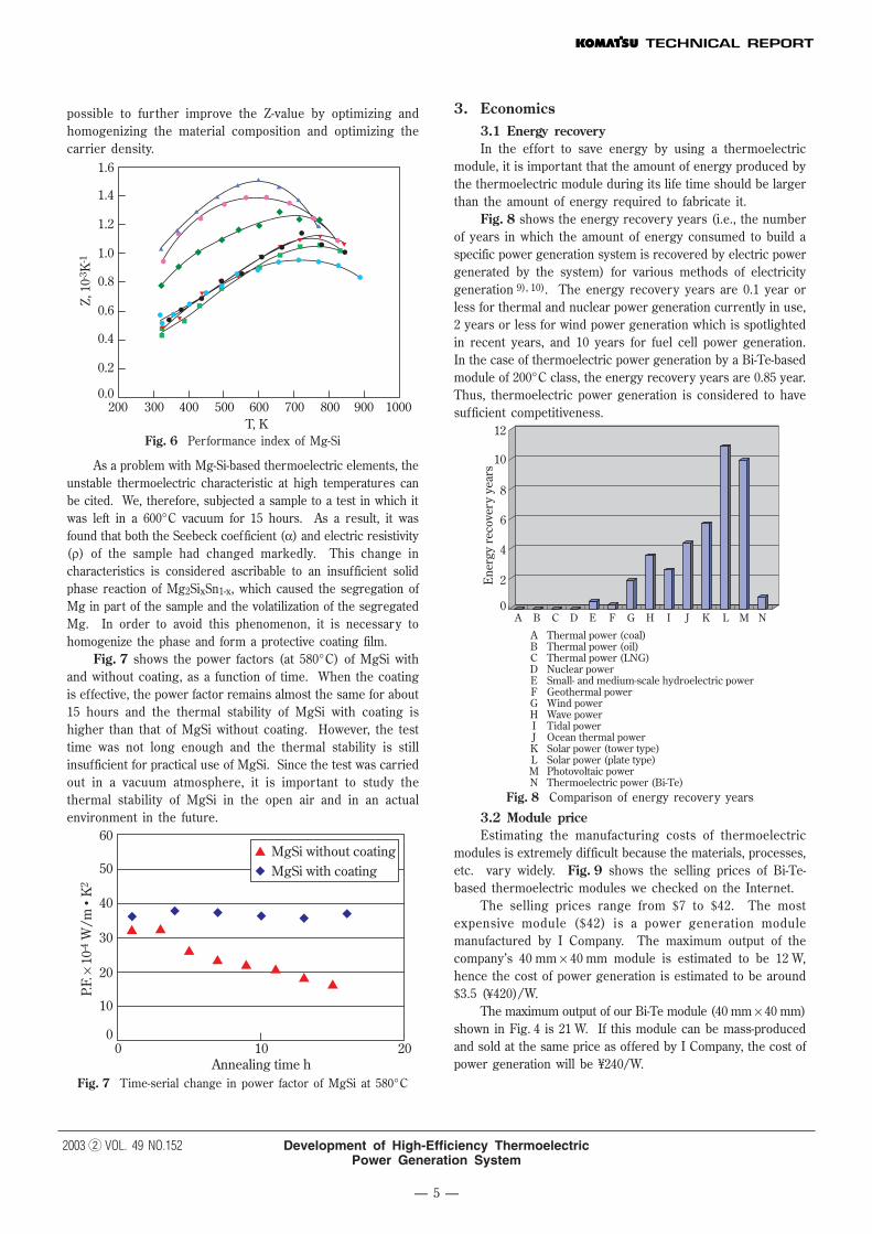
Fig. 8 shows the energy recovery years (i.e., the numberof years in which the amount of energy consumed to build aspecific power generation system is recovered by electric powergenerated by the system) for various methods of electricitygeneration 9), 10). The energy recovery years are 0.1 year orless for thermal and nuclear power generation currently in use,2 years or less for wind power generation which is spotlightedin recent years, and 10 years for fuel cell power generation.In the case of thermoelectric power generation by a Bi-Te-basedmodule of 200°C class, the energy recovery years are 0.85 year.Thus, thermoelectric power generation is considered to havesufficient competitiveness.
12
10
8
6
4
2
0
A Thermal power (coal) B Thermal power (oil) C Thermal power (LNG) D Nuclear power E Small- and medium-scale hydroelectric power F Geothermal power G Wind power H Wave power I Tidal power J Ocean thermal power K Solar power (tower type) L Solar power (plate type) M Photovoltaic power N Thermoelectric power (Bi-Te)
Ene
rgy
reco
very
yea
rs
A B C D E F G H I J K L M N
Fig. 8 Comparison of energy recovery years
3.2 Module priceEstimating the manufacturing costs of thermoelectric
modules is extremely difficult because the materials, processes,etc. vary widely. Fig. 9 shows the selling prices of Bi-Te-based thermoelectric modules we checked on the Internet.
The selling prices range from $7 to $42. The mostexpensive module ($42) is a power generation modulemanufactured by I Company. The maximum output of thecompany’s 40 mm × 40 mm module is estimated to be 12 W,hence the cost of power generation is estimated to be around$3.5 (¥420)/W.
The maximum output of our Bi-Te module (40 mm × 40 mm)shown in Fig. 4 is 21 W. If this module can be mass-producedand sold at the same price as offered by I Company, the cost ofpower generation will be ¥240/W.

Development of High-Efficiency ThermoelectricPower Generation System
2003 w VOL. 49 NO.152
— 6 —
3.3 System priceTable 2 shows the cost of a 3kW solar cell system for
general home (2001) 11). The major peripheral device is theinverter, which is considered necessary for a thermoelectricpower generation system too. Assuming the cost of thethermoelectric module as ¥240/W (shown above), the cost ofthe inverter and other peripheral devices as ¥155/W, and thecost of the heat exchanger as ¥110,000/kW, the system pricecomes to approximately ¥505/W. This level is consideredattainable without so much difficulty.
45.0040.0035.0030.0025.0020.0015.0010.005.000.00
0
Prices of 40 mm × 40 mm general-purpose modules;unit price when 100 units are purchased (surveyed by our company)
Com
pany
Com
pany
Com
pany
Com
pany
Com
pany
Com
pany
Com
pany
Com
pany
Com
pany
A B C D E F G H I
$
Fig. 9 Selling prices of various modules
Table 2 Cost of solar cell system
Solar cell
Module price ¥520/W
Peripheral devices ¥155/W
Standard installation work ¥110/W
Total ¥785/W
The economics of the system can be roughly calculatedas follows.
Yearly operating hours = 365 days year × 24 hours × 0.65(the rate of operation)
= 5,694 hours/yearElectric energy generated = 5,694 (hours/year) × 1 W
= 5.7kWh/yearSaving of energy = 5.7kWh/year × ¥10/kWh
= ¥57/year · WRecovery years = ¥505/W ÷ ¥57/year = 8.9 yearsCost of power generation = ¥505/W ÷ 5.7kWh/year ÷ 10 years
= ¥8.9/kWhTable 3 lists the costs of electric power for various
generation methods (2001) 12), 13).The cost of thermoelectric power generation is ¥8.9/kWh as
calculated above, and hence thermoelectric power generation isquite competitive. The above calculations assume that there issufficient heat source. If this condition is satisfied, we considerthat the possibility of power generation by a BiTe thermoelectricmodule being put into practical use is ver y strong. When acascade-type module which allows for more effective utilization ofthe high temperature side is developed, the economics of athermoelectric power generation system will be improved still better.
Table 3 Comparison of cost of electric power generation
Cost per kWh Service life
Hydropower ¥13.6
LNG ¥6.4 40 years
Oil ¥10.2 40 years
Nuclear power ¥5.9 40 years
Wind power ¥10 – ¥24
Photovoltaic power ¥66 20 years
Thermoelectric power 10 years
3.4 MarketWe aim at an energy conversion efficiency of 12% by
improving the performances of Bi-Te-based and silicide-basedthermoelectric modules and by cascading modules. Then, byintroducing them into a thermoelectric conversion systemproperly, it should become possible to obtain a thermoelectricconversion system ef ficiency of 6%. This is a significantprogress in view of the thermoelectric conversion efficiency of3.6% of conventional waste incinerators. Therefore, the waytoward practical application of thermoelectric power generationwill open wide.
Concerning the energy-saving effect of thermoelectric powergeneration, we shall study the application of a high-efficiencythermoelectric system to a diesel engine for cogeneration.
We estimate the overall effect in Japan as follows. It isexpected that diesel engine-based cogeneration will reach2,848MW by the end of 2010. The quantity of waste heat is nearlyequal to the electric power generated. Therefore, whenthermoelectric power generation is applied to all the cogenerationsystems, the energy recovered will be 2,848MW × 6% = 171MW.It is also expected that 120MW of cogeneration will be addedannually. Assuming that thermoelectric power generation isintroduced to all the new cogeneration systems in 2010, it will beapplied to 720MW, resulting the 25% of coverage.
The market will be ¥36,400 million by 2010, with ¥6,000million in 2010 alone.
The energy-saving effect will be 43MW/h, or 167GWhassuming the yearly operating hours as 3,900 hours. Thiscorresponds to the saving of 40,600 k¶ of crude oil per yearand the reduction of approximately 20,200 tons of CO2 per year.
5. AcknowledgementsThe present research and development were carried out
with the 2002 subsidy for the development of technologies forrationalizing the use of energy (development of innovative newtechnologies for coping with global warming: high-efficiencythermoelectric transformation system development project).
Development of High-Efficiency ThermoelectricPower Generation System
2003 w VOL. 49 NO.152
— 7 —
Introduction of the writersSeijiro SanoEntered Komatsu in 1971. Currentlyworking in Research Division, Komatsu.
Hiroyuki MizukamiEntered Komatsu in 1981. Currentlyworking in Technology Research Center,Research Division, Komatsu.
Hiromasa KaibeEntered Komatsu in 2000. Currentlyworking in Technology Research Center,Research Division, Komatsu.
[A few words from the writers]We would like to commercialize thermoelectric power
generation early.
6. References1) http://www.nedo.go.jp/informations/other/140814/
140814.html2) 2001 report on the results of operations entrusted by
NEDO; subsidized project to develop new technology forrationalizing the use of energy; “Study for Developmentof High-Ef ficiency Thermoelectric TransformationModules”, April 2002.
3) CRC Handbook of Thermoelectrics, edited by D.M.Rowe,CRC Press, Inc. (1995) Ch.22, pp.267
4) CRC Handbook of Thermoelectrics, edited by D.M.Rowe,CRC Press, Inc. (1995) Ch.21, pp.257
5) I.Terasaki, Y.Sasago and K.Uchinokura, Phys. Rev., B56,R12685(1997)
6) CRC Handbook of Thermoelectrics, edited by D.M.Rowe,CRC Press, Inc. (1995) Ch.25, pp.299
7) Thermoelectric Transformation Engineering — Basics andApplication; M. Sakata, Realize Co., March 2001, Part 2:1.9 Transition Metallic Silicides.
8) Generalized Report FY1997-FY2000, “The thermoelectricrecovery of waste heat”, Ref. GR1, NEDO Report
9) “Study of Energy Balance of 200°C Class PowerGeneration System”; New Energy/Environment StudyMeeting Data No. FTE-99-2; Y. Hori, T. Ito, J. Yamamoto,and T. Ota; February 1, 1999; JEC.
10) “Analysis of Energy Balance of Power Generation Plants”,Central Electric Power Research Institute, research report:Y90015, November 1991, Central Electric Power ResearchInstitute.
11) http://www.nedo.go.jp/taiyoshitsu/index.html12) http://www.nedo.go.jp/intro/shinene/pdf/s2_1.pdf13) http://www.iae.or.jp/energyinfo/energydata/data1012.html


![In‐situ TEM studies of nanostructured thermoelectric materials: … · cost and high conversion efficiency thermoelectric power generator (TEG).[22–28] Despite those advantages,](https://img.pdfslide.net/doc/110x75/5e37b76cded5da649801e808/inasitu-tem-studies-of-nanostructured-thermoelectric-materials-cost-and-high.jpg)


![CHARACTERISATION OF PERFORMANCES OF ......thermoelectric properties and a high thermoelectric figure of merit zT that correlates directly with the efficiency of the device [1], [2]](https://img.pdfslide.net/doc/110x75/5ff00633263a8c7094610cd6/characterisation-of-performances-of-thermoelectric-properties-and-a-high.jpg)