Embed Size (px)
Citation preview
JRRDJRRD Volume 46, Number 3, 2009
Pages 447–462
Journal of Rehabil itation Research & Development
Development of hybrid orthosis for standing, walking, and stair climbing after spinal cord injury
Rudi Kobetic, MS;1* Curtis S. To, MS;2 John R. Schnellenberger, MS;1 Musa L. Audu, PhD;2 Thomas C. Bulea, MS;2 Richard Gaudio, CO;3 Gilles Pinault, MD;1 Scott Tashman, PhD;4 Ronald J. Triolo, PhD1,51Louis Stokes Cleveland Department of Veterans Affairs Medical Center, Cleveland, OH; 2Department of Biomedical Engineering, Case Western Reserve University, Cleveland, OH; 3Orthotics and Prosthetics Specialties, Cleveland, OH; 4Department of Orthopaedic Surgery, University of Pittsburgh, Pittsburgh, PA; 5Department of Orthopaedics, Case Western Reserve University, Cleveland, OH
Abstract—This study explores the feasibility of a hybrid sys-tem of exoskeletal bracing and multichannel functional electri-cal stimulation (FES) to facilitate standing, walking, and stairclimbing after spinal cord injury (SCI). The orthotic compo-nents consist of electromechanical joints that lock and unlockautomatically to provide upright stability and free movementpowered by FES. Preliminary results from a prototype deviceon nondisabled and SCI volunteers are presented. A novel vari-able coupling hip-reciprocating mechanism either acts as astandard reciprocating gait orthosis or allows each hip to inde-pendently lock or rotate freely. Rotary actuators at each hip areconfigured in a closed hydraulic circuit and regulated by afinite state postural controller based on real-time sensor infor-mation. The knee mechanism locks during stance to preventcollapse and unlocks during swing, while the ankle is con-strained to move in the sagittal plane under FES-only control.The trunk is fixed in a rigid corset, and new ankle and trunkmechanisms are under development. Because the exoskeletalcontrol mechanisms were built from off-the-shelf components,weight and cosmesis specifications for clinical use have notbeen met, although the power requirements are low enough toprovide more than 4 hours of continuous operation with standardcamcorder batteries.
Key words: assistive technology, bracing, functional electricalstimulation, gait, hybrid systems, mobility, neuroprostheses,orthotics, paralysis, rehabilitation engineering, spinal cordinjury, stair climbing, standing, stepping.
INTRODUCTION
Inability to walk is often viewed as the major andmost traumatic outcome of thoracic spinal cord injury(SCI), motivating significant effort in the field of orthot-ics to restore locomotion to persons with paraplegia. Thethree major approaches to restoring upright mobilityreceiving the most attention are mechanical bracing,functional electrical stimulation (FES), and hybrid systemsthat combine elements of both orthotic and neuropros-thetic interventions.
Abbreviations: ECU = external control unit, FES = functionalelectrical stimulation, FSPC = finite-state postural controller,FSR = force-sensing resistor, GED = gait event detector, GUI =graphical user interface, HNP = hybrid neuroprosthesis, HRA =hydraulic rotary actuator, NC = normally closed, RGO = recip-rocal gait orthosis, SCI = spinal cord injury, SD = standarddeviation, T= thoracic, THKAFO = trunk-hip-knee-ankle-footorthosis, VCHM = variable constraint hip mechanism.*Address all correspondence to Rudi Kobetic, MS; MotionStudy Laboratory, 151A, Louis Stokes Cleveland Depart-ment of Veterans Affairs Medical Center, 10701 East Blvd,Cleveland, OH 44106; 216-791-3800, ext 4696; fax: 216-231-3433. Email: [email protected]:10.1682/JRRD.2008.07.0087
447
448
JRRD, Volume 46, Number 3, 2009
A variety of mechanical orthoses have been designedand tested for lower-limb function after SCI. In general,reciprocal gait orthosis (RGOs) stabilize ankles, knees,hips, and trunk to provide upright posture and couple hipflexion with contralateral hip extension to facilitate walk-ing, while long leg braces only fix the ankle and kneejoints to provide stability and prevent collapse. In someconfigurations, the addition of a pelvic band providesextra stability. Most orthoses provide good postural sta-bility, especially when the hip joints are reciprocally cou-pled to prevent bilateral hip flexion. The coupling alsoreduces metabolic energy consumption in a more natural-appearing reciprocal gait than the swing-through gait typi-cal with long leg braces where both legs are brought for-ward together [1]. No significant difference in energyconsumption was found between different reciprocal gaitorthosis designs [2]. With all mechanical braces, upper-body strength is required for standing up and for forwardprogression during walking. Clinical reviews also indi-cate that brace users are consistently unable to achievesignificant functional ambulation without some sort ofpelvic control, that adequate hip flexion is an essentialcomponent of walking with braces, and that few individ-uals with paraplegia choose to use their orthosis for activi-ties other than therapeutic exercise [3–4].
FES has been introduced in an effort to circumventsome of the shortcomings of mechanical orthoses [5].Activation of one’s own paralyzed muscles can stabilizethe body against collapse and provide the power for for-ward progression. Many configurations of FES systemshave been used to enable walking in persons with para-plegia [6]. Those configurations using electrodes appliedto the surface of the skin are usually limited to six chan-nels or less, with emphasis on locking the knees and hipsin extension and eliciting a withdrawal reflex to move thelegs for stepping [7]. FES systems using implanted intra-muscular electrodes with percutaneous leads [8–11] haveprovided up to 48 channels of stimulation for improvedstability and forward progression and finer control ofmovement during walking [12–13]. Multichannelimplanted FES systems for walking after motor completeparaplegia have provided a swing-through [14–15] andreciprocal gait [16–18]. They reduced donning time andimproved day-to-day repeatability compared with surfaceFES systems and eliminated site care of percutaneoussystems. Most FES systems for walking employ open-loop or feed-forward control, in which preprogrammedstimulation patterns are activated for each step by
switches or the electromyographic activity of nonpara-lyzed muscles [19]. However, rapid onset of musclefatigue remains a major problem that more effective con-trol of stimulation still needs to resolve. Consequently,FES walking in paraplegia requires high levels of meta-bolic energy [20] and remains primarily experimentaland for therapeutic exercise [21–22].
In 1973, a hybrid actuator was described for orthoticsystems in which the anatomical joint could be controlledinternally by means of FES or externally by means of ahypothetical three-state joint actuator incorporated ontoan exoskeletal brace [23]. This work initiated the field ofhybrid orthotics and, specifically, defined the concept ofa hybrid neuroprosthesis (HNP), in which FES is com-bined with external mechanical components. This articlereviews the design specifications for HNP systems andpresents preliminary data on the performance of a newprototype device incorporating a novel hip reciprocatingmechanism with variable coupling that allows stairascent/descent and stride length variation with walkingspeed.
BACKGROUND
HNPs potentially can combine the best features ofmechanical bracing and FES into new systems for walk-ing after SCI that offer more advantages than the individ-ual components acting alone. The exoskeletal mechanicalcomponents of hybrid systems have been generally pas-sive devices to minimize size, weight, and energy con-sumption, while the FES component serves as an activemechanism for limb propulsion. Kinematic constraintsimposed on the user by the exoskeleton reduce the num-ber of degrees of freedom driven by FES. Therefore, thesecondary and tertiary actions of the stimulated musclesare constrained by the exoskeleton without the need tocompensate by activating antagonist muscles.
Various prototype lower-limb exoskeletons use auxil-iary passive mechanisms to reduce the number of mus-cles to be electrically stimulated. The controlled-brakeorthosis incorporated magnetic particle brakes at the hipand knee joints to refine the sagittal limb dynamicsdriven by FES [24–25]. Another approach used a cam-slider mechanism to synchronize knee flexion with ankledorsiflexion to assure proper foot-ground clearance dur-ing swing [26]. The spring-brake orthosis used excessspring energy stored from FES driven knee extension to
449
KOBETIC et al. Hybrid orthosis for walking in SCI
facilitate knee flexion and assist hip flexion in the suc-ceeding ipsilateral swing period [27]. Similarly, a designof an energy-storing orthosis that employed a pneumaticsystem that harnesses and transfers excess energy fromknee extension to facilitate ipsilateral hip extension duringstance showed promising results in bench testing [28].
Surface [29–38] and intramuscular [39–41] FES sys-tems have been combined with a conventional trunk-hip-knee-ankle-foot orthosis (THKAFO) for reciprocal gaitin individuals with complete thoracic level SCI. Combin-ing an RGO with a four-channel surface FES system pro-vided a 16 percent reduction in energy expenditure forsubjects with SCI level between thoracic (T), levels T1and T10 relative to walking with the RGO only at a speedof 0.2 m/s [42]. The addition of FES to the glutei duringstance when individuals used lower-limb bracing reducedcrutch forces [43–44] and provided forward propulsionby driving the stance leg into extension. Users with para-plegia (complete T4–T12 SCI) required 70 percent oftheir maximum upper-limb aerobic capacity when walk-ing with an RGO alone, while walking with an RGOcombined with FES required 32 percent of the upper-limb and 25 percent of the lower-limb aerobic capacity,effectively shifting the metabolic burden from the mus-cles of the arms, shoulders and trunk to the large, otherwiseparalyzed, muscles of the legs [45]. Further, individualswith paraplegia have been shown to walk significantlylonger with a hybrid system than with either brace-onlyor FES-only systems, with hybrid users achieving anaverage maximum walking distance of 800 m [36].
FES-only systems require the user to maintain trunkstability via significant upper-body forces on a walker orother assistive device. This increases energy consumptionand thus reduces walking times and distances. Instabilityof the trunk is often exacerbated by stimulation of the hipflexors during the initiation of the swing phase. Anteriortrunk tilt of up to 40° has been associated with FES-onlygait systems. The RGO combined with FES has beenshown to reduce anterior trunk tilt to less than 18° [41].However, the RGO has a fixed 1:1 hip flexion:extensioncoupling ratio (hip flexion is limited by the degree ofcontralateral hip extension). Individuals with paraplegiawalking with the RGO only (no FES) at a 2:1 hip flex-ion:extension coupling ratio exhibited a 15 percentreduction in physiological cost index and 4 percentincrease in stride length relative to an RGO with a 1:1coupling ratio [46]. Adding FES-assisted hip flexion toan RGO with a 2:1 hip coupling ratio reduced the physio-
logical cost index further and increased stride length andwalking speed. A reciprocating mechanism with a fixed1:1 coupling ratio can actually compromise peak walkingperformance. When a multichannel FES system wascombined with a 1:1 coupled RGO fitted with a control-lable locking mechanism at the knee joint to allow forknee flexion during swing, the average stride length andgait speed were significantly lower (0.64 m and 0.32 m/s,respectively) than when the reciprocator was disengaged(0.94 m and 0.49 m/s.) However, disengaging the recip-rocator significantly compromised the postural stability,requiring increased upper-limb exertion [40].
With the incorporation of joint locks or brakes, stand-ing and stance-limb stability against collapse can beaccomplished with minimal muscle stimulation. Theselocks must be properly controlled and synchronized withboth the gait cycle and FES to provide stability whenneeded, without restricting joint motion necessary forambulation. A knee joint, which unlocks and locks by theweight of the locking bar, obviated the need for stimula-tion of quadriceps during standing and the stance phaseof gait [47]. With applied flexion moment, unlocking hasbeen a problem in designs based on cam and follower[48], roller clutches, lever locks, and wedge knees asemployed in orthotic stance-phase control knee joints[49]. A commercial pendulum-locking knee joint thatlocks when the limb is extended in front of the user andunlocks shortly after midstance can allow swing-phaseflexion [50]. Another mechanism uses a push rod dis-placed by body weight to engage the knee lock [51–52].A wrap-spring clutch-controlled knee joint that wouldlock during stance and be free for swing [53] showed sig-nificant reduction in oxygen consumption during walkingwhen compared with a locked knee brace [54].
In summary, an HNP combining bracing and FES hasbeen shown to significantly improve walking distanceand reduce energy consumption. A reciprocal coupling ofthe hips provides good trunk stability, and flexion-to-extension coupling ratios favoring flexion improve steplength and energy cost. Unlocking the orthotic kneejoints during the swing phase of gait improves foot-to-floor clearance and reduces energy cost, while locking themduring stance postpones muscle fatigue from stimulation.
In this article, we discuss the development of an HNPthat incorporates and expands the advantages of varioushybrid configurations that were found to improve walkingin people with paraplegia. These include a novel variable-constraint hip mechanism that either reciprocally couplesthe hips or individually locks them or allows them to
450
JRRD, Volume 46, Number 3, 2009
move freely. This mechanism stabilizes the hips andtrunk when coupled, while allowing increased hip flexionwhen uncoupled during swing to improve step length andmaintain stance hip stability. The knee joints duringswing are unlocked to provide foot-to-floor clearance andlocked during stance to allow muscles to relax. This sys-tem includes control over all major muscles of the trunk,hips, knees, and ankles with an implanted FES system. Itprovides the power to bring the legs forward for steppingby direct muscle activation rather than the withdrawalreflex and moves the body forward by activation of hipextensors and plantar flexors. The coordination of jointcoupling and locking with muscle activation is based onsensor information fed to a gait event detector (GED).The GED is in turn used by a postural controller, whichassures proper coordination of stimulation and joint lock-ing mechanisms and provides safety against collapse.
METHODS
HNP Design SpecificationsA set of general design specifications for HNP sys-
tems was established and applied to the development andtesting of a new prototype system. To achieve a practicalsystem for upright mobility in paraplegia, we found itcritical to combine FES and bracing in a coordinatedfashion that takes advantage of the best features of eachcomponent. Bracing must be designed to provide posturalstability without excessively hindering movements dur-ing forward progression. On the other hand, the FES sys-tem should provide major power for forward progressionin an effective way that reduces muscle fatigue throughcontrol of the muscle stimulation patterns that adapt tothe changing muscle properties and environment duringgait. A practical HNP should possess the followingcharacteristics: 1. Be cosmetic. 2. Be easy to don and doff in less than 5 minutes with-
out assistance while sitting in a chair. 3. Be easy and intuitive to operate. 4. Provide the capability to stand up and sit down with
minimal effort. 5. Provide postural support without power or stimula-
tion for standing. 6. Provide the capability to go up and down stairs. 7. Carry its own weight. 8. Provide up to an hour of continuous walking.
9. Provide safety features in case of power failure.10. Require less than 50 percent of individual’s maximal
aerobic capacity to walk.Other HNP specifications that would improve the use
and practicality include— 1. Mechanical components of the HNP complement the
functional movements generated by FES. 2. The HNP minimizes and automatically adjusts mus-
cle stimulation. 3. The HNP seamlessly combines bracing and FES sys-
tem components.The HNP system under development consists of an
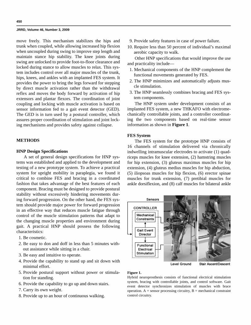
implanted FES system, a new THKAFO with electrome-chanically controllable joints, and a controller coordinat-ing the two components based on real-time sensorinformation as shown in Figure 1.
FES SystemThe FES system for the prototype HNP consists of
16 channels of stimulation delivered via chronicallyindwelling intramuscular electrodes to activate (1) quad-riceps muscles for knee extension, (2) hamstring musclesfor hip extension, (3) gluteus maximus muscles for hipextension, (4) gluteus medius muscles for hip abduction,(5) iliopsoas muscles for hip flexion, (6) erector spinaemuscles for trunk extension, (7) pretibial muscles forankle dorsiflexion, and (8) calf muscles for bilateral ankle
Figure 1.Hybrid neuroprosthesis consists of functional electrical stimulationsystem, bracing with controllable joints, and control software. Gaitevent detector synchronizes stimulation of muscles with braceoperation. A = sensor processing circuitry, B = mechanical constraintcontrol circuitry.
451
KOBETIC et al. Hybrid orthosis for walking in SCI
plantar flexion. Electrodes can be connected temporarilyto an external control unit (ECU) percutaneously or per-manently to an implanted pulse generator powered andcontrolled via radio frequency by an ECU [16].
The ECU is powered by an internal Sony 15.8 WhNP-F570 7.2–8.4 V lithium ion rechargeable battery pack(Sony Corporation of America; New York, New York).The ECU draws approximately 2 W of power for FES,allowing for approximately 8 hours of muscle activation.
Bracing SystemBecause conventional RGOs have a fixed 1:1 hip
flexion:extension coupling ratio, which has been shownto limit stride length and gait speed [35,40], a variableconstraint hip mechanism (VCHM) was designed tomaintain posture while allowing for uninhibited sagittalhip movement [55]. The objective of the VCHM was toprovide good hip and trunk stability and erect posturewithout interfering with functional lower-limb dynamicmovements during walking and stair-climbing. The recipro-cating bar of a standard isocentric RGO was replacedwith the new VCHM and the medial uprights wereremoved. The resulting THKAFO is coupled to the bodyby means of chest, pelvic, and below-the-knee straps.
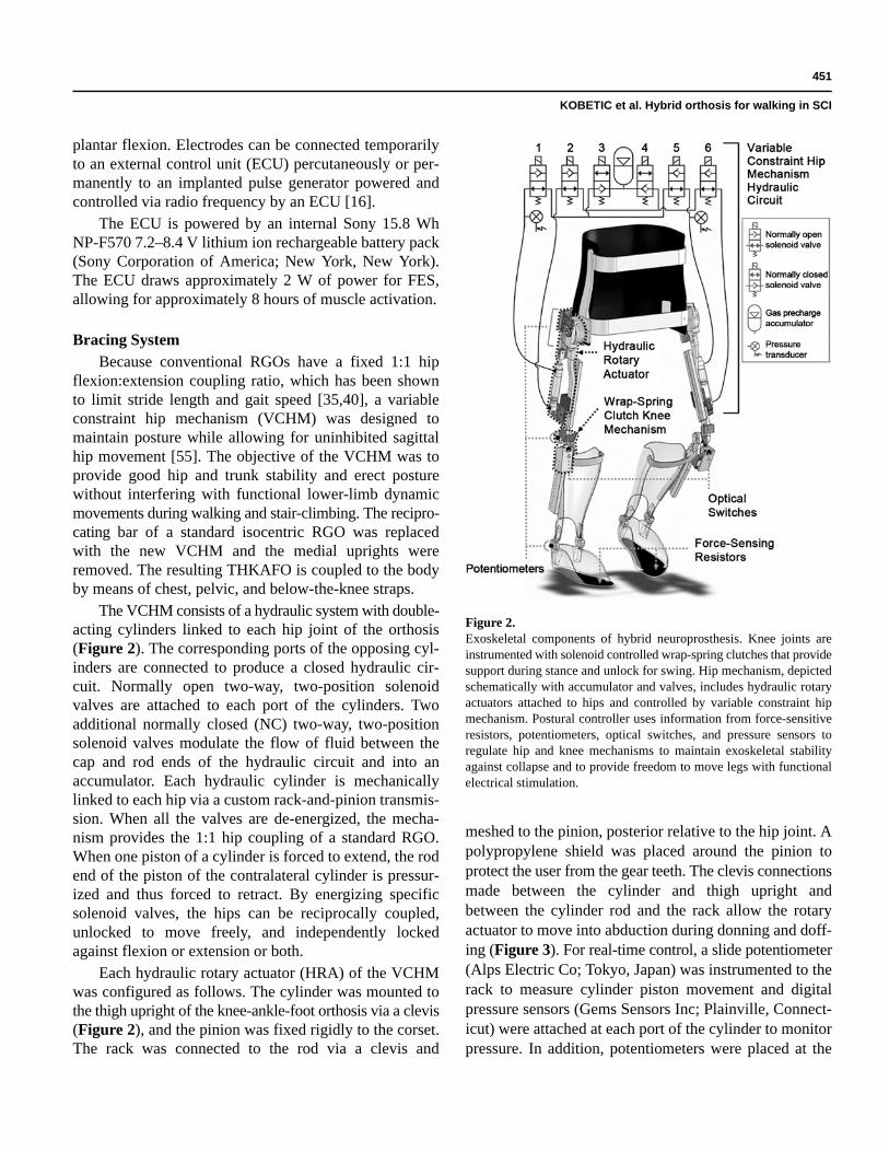
The VCHM consists of a hydraulic system with double-acting cylinders linked to each hip joint of the orthosis(Figure 2). The corresponding ports of the opposing cyl-inders are connected to produce a closed hydraulic cir-cuit. Normally open two-way, two-position solenoidvalves are attached to each port of the cylinders. Twoadditional normally closed (NC) two-way, two-positionsolenoid valves modulate the flow of fluid between thecap and rod ends of the hydraulic circuit and into anaccumulator. Each hydraulic cylinder is mechanicallylinked to each hip via a custom rack-and-pinion transmis-sion. When all the valves are de-energized, the mecha-nism provides the 1:1 hip coupling of a standard RGO.When one piston of a cylinder is forced to extend, the rodend of the piston of the contralateral cylinder is pressur-ized and thus forced to retract. By energizing specificsolenoid valves, the hips can be reciprocally coupled,unlocked to move freely, and independently lockedagainst flexion or extension or both.
Each hydraulic rotary actuator (HRA) of the VCHMwas configured as follows. The cylinder was mounted tothe thigh upright of the knee-ankle-foot orthosis via a clevis(Figure 2), and the pinion was fixed rigidly to the corset.The rack was connected to the rod via a clevis and
meshed to the pinion, posterior relative to the hip joint. Apolypropylene shield was placed around the pinion toprotect the user from the gear teeth. The clevis connectionsmade between the cylinder and thigh upright andbetween the cylinder rod and the rack allow the rotaryactuator to move into abduction during donning and doff-ing (Figure 3). For real-time control, a slide potentiometer(Alps Electric Co; Tokyo, Japan) was instrumented to therack to measure cylinder piston movement and digitalpressure sensors (Gems Sensors Inc; Plainville, Connect-icut) were attached at each port of the cylinder to monitorpressure. In addition, potentiometers were placed at the
Figure 2.Exoskeletal components of hybrid neuroprosthesis. Knee joints areinstrumented with solenoid controlled wrap-spring clutches that providesupport during stance and unlock for swing. Hip mechanism, depictedschematically with accumulator and valves, includes hydraulic rotaryactuators attached to hips and controlled by variable constraint hipmechanism. Postural controller uses information from force-sensitiveresistors, potentiometers, optical switches, and pressure sensors toregulate hip and knee mechanisms to maintain exoskeletal stabilityagainst collapse and to provide freedom to move legs with functionalelectrical stimulation.
452
JRRD, Volume 46, Number 3, 2009
knee and ankle to measure angles and force-sensingresistors (FSRs) (B & L Engineering; Tustin, California)were placed in the insoles to measure foot-to-floor contact.
A solenoid-actuated wrap-spring clutch mechanismbased on a design by Irby et al. was employed for sup-porting the knee (Figure 2) [53]. The wrap-spring clutchknee mechanism was installed at the knee joints of theexoskeleton with a posterior offset to reduce knee flexionmoment induced by gravity. A 5.9 W, 12 Vdc latchingsolenoid (Guardian Electric; Woodstock, Illinois) wasused to engage/disengage the wrap-spring clutch (WarnerElectric; South Beloit, Illinois). Unlatching (extension ofthe plunger out of the solenoid) disengages the clutch,which locks the knee against flexion but still allowsextension. Latching (retraction of the plunger into thesolenoid) engages the clutch, allowing for both knee flex-ion and extension. A pulse of 100 ms is used to latch/unlatch the latching solenoid. An optical switch (TTElectronics; Weybridge, United Kingdom) monitors themovement of the plunger of each latching solenoid toassure that the state transition (lock/unlock) of the kneehas been completed.
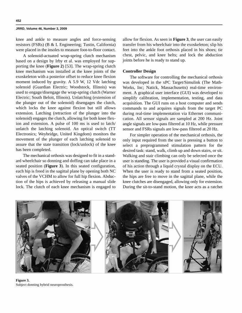
The mechanical orthosis was designed to fit in a stand-ard wheelchair so donning and doffing can take place in aseated position (Figure 3). In this seated configuration,each hip is freed in the sagittal plane by opening both NCvalves of the VCHM to allow for full hip flexion. Abduc-tion of the hips is achieved by releasing a manual slidelock. The clutch of each knee mechanism is engaged to
allow for flexion. As seen in Figure 3, the user can easilytransfer from his wheelchair into the exoskeleton; slip hisfeet into the ankle foot orthosis placed in his shoes; tiechest, pelvic, and knee belts; and lock the abductionjoints before he is ready to stand up.
Controller DesignThe software for controlling the mechanical orthosis
was developed in the xPC Target/Simulink (The Math-Works, Inc; Natick, Massachusetts) real-time environ-ment. A graphical user interface (GUI) was developed tosimplify calibration, implementation, testing, and dataacquisition. The GUI runs on a host computer and sendscommands to and acquires signals from the target PCduring real-time implementation via Ethernet communi-cation. All sensor signals are sampled at 200 Hz. Jointangle signals are low-pass filtered at 10 Hz, while pressuresensor and FSRs signals are low-pass filtered at 20 Hz.
For simpler operation of the mechanical orthosis, theonly input required from the user is pressing a button toselect a preprogrammed stimulation pattern for thedesired task: stand, walk, climb up and down stairs, or sit.Walking and stair climbing can only be selected once theuser is standing. The user is provided a visual confirmationof his action through a liquid crystal display on the ECU.When the user is ready to stand from a seated position,the hips are free to move in the sagittal plane, while theknee clutches are disengaged, allowing only for extension.During the sit-to-stand motion, the knee acts as a ratchet
Figure 3.Subject donning hybrid neuroprosthesis.
453
KOBETIC et al. Hybrid orthosis for walking in SCI
mechanism to provide resistance against knee flexion.The user is driven to a standing position through a combi-nation of FES of trunk, hip, and knee extensors andupper-limb effort against a walking aid. Calibration of allsensors occurs automatically as soon as the user hasachieved quiet standing. Sitting is accomplished by freeingboth the hips and knees, allowing users to lower them-selves down by gradually ramping down the stimulation.
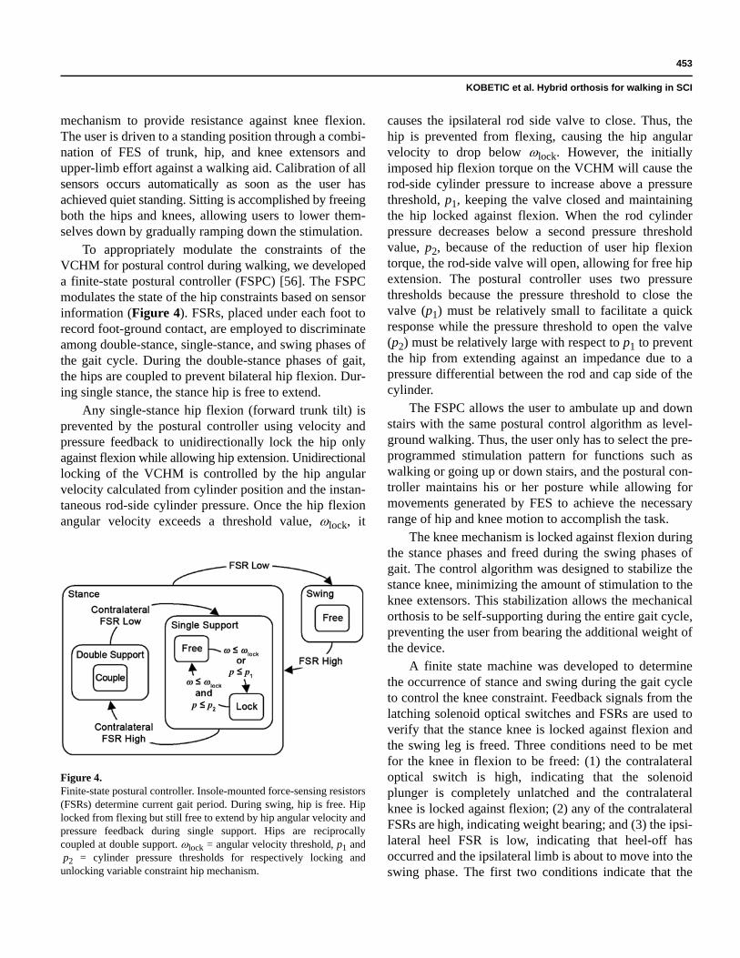
To appropriately modulate the constraints of theVCHM for postural control during walking, we developeda finite-state postural controller (FSPC) [56]. The FSPCmodulates the state of the hip constraints based on sensorinformation (Figure 4). FSRs, placed under each foot torecord foot-ground contact, are employed to discriminateamong double-stance, single-stance, and swing phases ofthe gait cycle. During the double-stance phases of gait,the hips are coupled to prevent bilateral hip flexion. Dur-ing single stance, the stance hip is free to extend.
Any single-stance hip flexion (forward trunk tilt) isprevented by the postural controller using velocity andpressure feedback to unidirectionally lock the hip onlyagainst flexion while allowing hip extension. Unidirectionallocking of the VCHM is controlled by the hip angularvelocity calculated from cylinder position and the instan-taneous rod-side cylinder pressure. Once the hip flexionangular velocity exceeds a threshold value, ωlock, it
causes the ipsilateral rod side valve to close. Thus, thehip is prevented from flexing, causing the hip angularvelocity to drop below ωlock. However, the initiallyimposed hip flexion torque on the VCHM will cause therod-side cylinder pressure to increase above a pressurethreshold, p1, keeping the valve closed and maintainingthe hip locked against flexion. When the rod cylinderpressure decreases below a second pressure thresholdvalue, p2, because of the reduction of user hip flexiontorque, the rod-side valve will open, allowing for free hipextension. The postural controller uses two pressurethresholds because the pressure threshold to close thevalve (p1) must be relatively small to facilitate a quickresponse while the pressure threshold to open the valve(p2) must be relatively large with respect to p1 to preventthe hip from extending against an impedance due to apressure differential between the rod and cap side of thecylinder.
The FSPC allows the user to ambulate up and downstairs with the same postural control algorithm as level-ground walking. Thus, the user only has to select the pre-programmed stimulation pattern for functions such aswalking or going up or down stairs, and the postural con-troller maintains his or her posture while allowing formovements generated by FES to achieve the necessaryrange of hip and knee motion to accomplish the task.
The knee mechanism is locked against flexion duringthe stance phases and freed during the swing phases ofgait. The control algorithm was designed to stabilize thestance knee, minimizing the amount of stimulation to theknee extensors. This stabilization allows the mechanicalorthosis to be self-supporting during the entire gait cycle,preventing the user from bearing the additional weight ofthe device.
A finite state machine was developed to determinethe occurrence of stance and swing during the gait cycleto control the knee constraint. Feedback signals from thelatching solenoid optical switches and FSRs are used toverify that the stance knee is locked against flexion andthe swing leg is freed. Three conditions need to be metfor the knee in flexion to be freed: (1) the contralateraloptical switch is high, indicating that the solenoidplunger is completely unlatched and the contralateralknee is locked against flexion; (2) any of the contralateralFSRs are high, indicating weight bearing; and (3) the ipsi-lateral heel FSR is low, indicating that heel-off hasoccurred and the ipsilateral limb is about to move into theswing phase. The first two conditions indicate that the
Figure 4. Finite-state postural controller. Insole-mounted force-sensing resistors(FSRs) determine current gait period. During swing, hip is free. Hiplocked from flexing but still free to extend by hip angular velocity andpressure feedback during single support. Hips are reciprocallycoupled at double support. ωlock = angular velocity threshold, p1 andp2 = cylinder pressure thresholds for respectively locking andunlocking variable constraint hip mechanism.
454
JRRD, Volume 46, Number 3, 2009
contralateral limb is in stance phase and supporting theuser, while the third indicates the transition from double-to single-limb support.
The HNP was designed to require no power duringquiet standing because (1) no FES-induced muscularcontractions are required as a result of the constraintsprovided by the mechanical orthosis and (2) the VCHMand the knee mechanisms require no power when the hipsare reciprocally coupled and the clutches are disengaged,thus stabilizing the hips and knees, respectively. Thisconserves electrical and biological energy while bothextending battery life and avoiding muscular fatigue.
Custom-designed circuitry was made for powering,controlling, and driving the mechanical orthosis and forproviding signal conditioning for the sensors. A Sony47.5 Wh (6,600 mAh) NP-F970 7.2–8.4-V lithium ionbattery powers the VCHM solenoid valves as well as theknee mechanism latching solenoids through a 12-Vdc/dcconverter. The sensors and associated processing cir-cuitry consume a total current of approximately 110 mAand are currently powered in the laboratory by a 14 Vrack-mounted isolated power supply.
The battery voltages of the ECUs for the FES systemand for the bracing system are monitored by comparatorcircuits, which generate an audio signal when the voltagedrops below 6.9 V. Testing has shown that the batteriescontinue to function down to approximately 5.6 V. Anaudio signal notifies the user when the battery voltagedrops to 6.9 V, providing the user sufficient time to reacha safe location where the battery can be replaced orrecharged. Furthermore, power loss causes the operationof the VCHM to default to reciprocally couple the hipswith a standard 1:1 coupling as in a conventional RGO.The knee joints remain locked against flexion with wrap-spring clutches to prevent collapse. Therefore, users cansafely ambulate as they would with an RGO and standwithout upper-body exertion on a walking aid in theevent of catastrophic power failure.
Bench TestingWe performed bench tests to measure passive resis-
tance of the VCHM and to determine thresholds for theFSPC [55–56]. The passive resistance was a measure oftorque necessary to drive the hip at various angularvelocities representative of paraplegic gait with the hipscoupled or free to move independently. The movementwas controlled with a dynamometer (Biodex MedicalSystems; Shirley, New York).
Similarly, we determined postural controller thresholdvalues of the angular velocity (ωlock) and cylinder pres-sures (p1 and p2) during bench testing of the VCHMusing the dynamometer to simulate hip dynamics duringgait. Three trials were conducted for each thresholdvalue. We chose values for ωlock and p2 to minimize hipflexion angle and the dynamometer-applied extensionmoment, respectively. Even if the VCHM is uncoupled(both hips are independently free), movement of oneHRA can influence the pressure measured on the con-tralateral HRA, because the VCHM is a closed hydraulicsystem. As a result, flexion of the contralateral swing hipcan cause accidental locking of the stance hip. We deter-mined the value of p1 to prevent this effect. With theVCHM uncoupled, the hip joint was actuated at variousflexion angular velocities by the dynamometer while wemeasured the pressure of the contralateral cylinder.
Nondisabled Subject TestingTwo nondisabled subjects were recruited and signed
an informed consent form approved by the Louis StokesDepartment of Veterans Affairs Medical Center Institu-tional Review Board (committee on human subjects’ pro-tection in research) prior to participation. Both subjectsweighed approximately 70 kg.
The ability of the VCHM to safely support the userduring unstable trunk movement was tested for the twomodes of the postural controller: (1) single stance and(2) double stance. In both tests, the subjects were stand-ing wearing THKAFO with the VCHM. In the first case,single stance was simulated with the subject in quietstance and the FSRs in one foot insole disabled. The sub-jects were then instructed to forcibly tilt their trunk for-ward. In the second case, the subjects stood initially inquiet stance. The subjects were then instructed to stepforward and forcibly tilt their trunk forward upon heelstrike. We calculated the torque applied by the subject onthe VCHM from the measured cylinder pressures.
To evaluate whether the postural and knee controllerscan reliably modulate the constraints of the hip and kneeover level ground walking as intended, we instructed thenondisabled subjects to walk with the exoskeleton atthree different speeds: slow, preferred, and fast. For eachspeed, each subject walked 10 times across an 8 m walk-way. We collected approximately three to four completestrides of data for each walk by using a 16-camera ViconMX (Vicon; Oxford, United Kingdom) motion analysissystem. Sagittal joint angles, cylinder pressures, foot-
455
KOBETIC et al. Hybrid orthosis for walking in SCI
ground contact information, and valve and solenoidactivity were measured. Since nondisabled gait is approxi-mately periodic, we assumed the measured signals wereinvariant with respect to the same gait event among sub-sequent gait cycles. The gait cycle was divided into sixgait events: loading response, mid-stance, terminalstance, preswing, initial swing, and late swing [57]. Weautomated gait event determination by using forefoot andheel contacts with the ground.
The hip and knee controllers were also evaluated forstair ascent. The controllers were designed such that nochanges are required between level-ground walking andstair ascent. A trial consisted of a nondisabled subjectwalking up two steps with the FSPC and the knee con-troller and then descending two steps without the control-lers with the constraints freed (controller development forstair descent has yet to be completed). Both subjectschose to ascend a stair step by first stepping up with theright limb, then raising the left limb to the same stair stepas the right limb. The trial was repeated five times foreach subject. The same signals were collected as in thelevel-ground walking trials.
Additional tests involved a nondisabled subject walkingon a treadmill with the FSPC and knee controller activewhile power consumption of the system was measured.
SCI Subject TestingInitial testing was conducted with one subject weigh-
ing 68 kg, who had paraplegia resulting from completeSCI (T7, American Spinal Injury Association A). Thesubject signed an informed consent form approved by theLouis Stokes Department of Veterans Affairs MedicalCenter Institutional Review Board prior to participation.The subject was implanted with a multichannel percuta-neous intramuscular FNS system and had more than17 years experience with the system for exercise andwalking [22]. A user-specific set of muscle stimulationpatterns, based on established rules for generating FESwalking [12], was preprogrammed into the ECU. Thestimulation pattern was tuned to a comfortable walkingspeed. Because the VCHM was designed to stabilizeagainst extrinsic/intrinsic perturbation throughout theentire gait cycle, the FSPC did not need to be synchro-nized with FES. The knee constraint unlocking/lockingwas synchronized with the onset/offset of electrical stimu-lation. The knee controller used feedback signal from themuscle stimulator, which indicated the exact timing ofthe onset/offset of electrical stimulation to knee flexors/
extensors. The torque applied on the VCHM was deter-mined from cylinder pressure data and the knee constraintstate was recorded.
RESULTS
The passive resistance of the VCHM was found tohave a negligible effect on the movement of the hipjoints. When the hips were uncoupled and independentlyfree to move, the median resistive torques measured wereless than 2 N·m at angular velocities below 45°/s and lessthan 5 N·m at angular velocities below 90°/s. When thehips were reciprocally coupled, the median resistivetorque was less than 4 N·m and 6 N·m, respectively, forthe low and high hip angular velocities. This amount oftorque required to actuate the VCHM translates to lessthan 10 percent of the achievable hip torque generated byFES [12].
Bench testing for threshold values for the posturalcontroller of the VCHM showed that the maximum noiseinherent in the hip angular velocity control signal usedfor feedback in the FSPC was ±3°/s. To prevent the hipfrom accidentally locking at 0°/s, we had to determine athreshold that exceeded the maximum noise amplitude.The resulting hip-flexion angles at hip locking for ωlockvalues between 4°/s and 10°/s were not statistically dif-ferent (p = 0.08). Thus, a ωlock value between 4°/s and10°/s was found acceptable for the FSPC. Because thehip flexion angular velocity in paraplegia generally doesnot exceed 60°/s [58] and the changes in cylinder pres-sure were less than 5 psi at angular velocities up to 75°/s,p1 values between 5 and 10 psi were found suitable forthe FSPC. A hip-extension torque was required to unlockthe VCHM for cylinder pressure p2 values of less than 30psi. Therefore, a p2 value greater than 30 psi was foundacceptable for the postural controller. However, the p2was limited to 70 psi, because at greater values the cylin-der pressure did not exceed this threshold when the hipwas locked, and the hip unlocked when the cylinder pres-sure dropped below the p1 threshold, which required sig-nificantly greater extension moment to unlock the hip.
The nondisabled safety trials verified that the VCHMprovided adequate support to the user during instances oftrunk instability and confirmed that the VCHM and theknee mechanism both changed states as intended duringgait. The mean ± standard deviation (SD) maximumtorque applied to the VCHM in the single and double
456
JRRD, Volume 46, Number 3, 2009
stance were 28 ± 9 N·m and 26 ± 11 N·m for Subject 1,and 20 ± 10 N·m and 24 ± 9 N·m for Subject 2, respec-tively. The maximum applied torque to the VCHM was42 N·m.
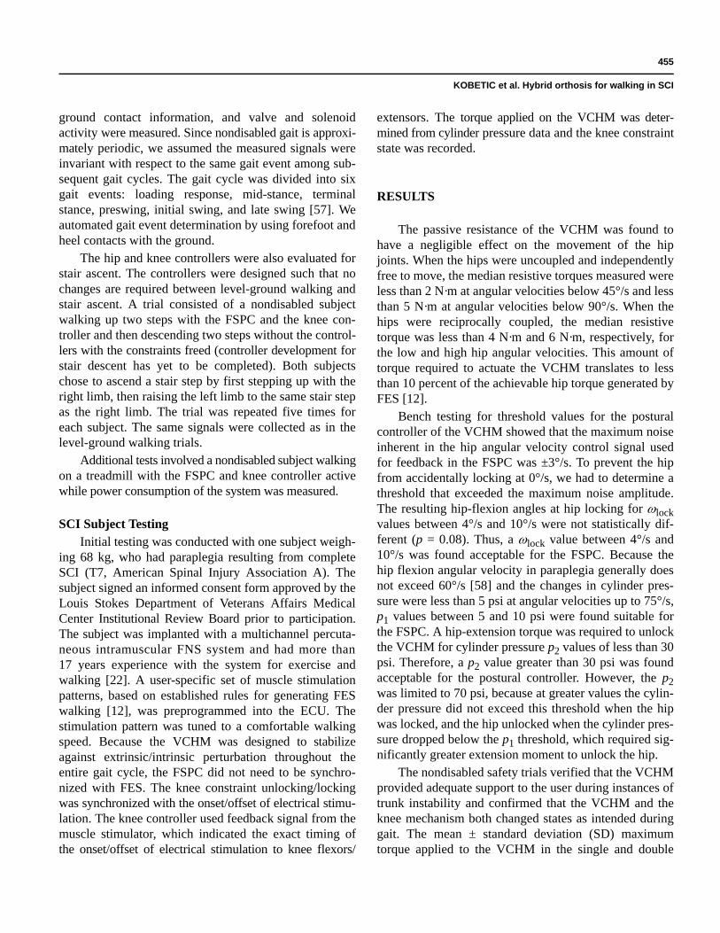
Figure 5 shows the mean ± SD hip and knee angleswith respect to percentage gait cycle of the right limb ofnondisabled Subject 1 walking with the exoskeleton ofthe HNP. The vertical lines partition the gait cycle intosix gait events [57]. The horizontal bars under the plot ofhip angle indicate the average periods of hip couplingprimarily during the loading response and preswing,which are the double-stance phases of the gait cycle. Thehip locking against flexion during single stance for eitherlimb is not shown, because its occurrence was not signif-icant when averaged over multiple strides. The horizontalbar under the plot of knee angle indicates the averageperiod when the knee was locked. An optical switch mea-sured when each solenoid was completely latched/unlatched. However, the engagement (unlocked) and dis-engagement (locked) of a clutch does not require that thesolenoid be completely latched and unlatched, respec-
tively. The dark horizontal bars designate the periodwhen the solenoids were completely unlatched while thelighter bars designate the transition period of each sole-noid from latched to unlatched and vice versa. Locking ofthe knee generally occurred at the beginning of loadingresponse, while unlocking occurred at mid-preswing.
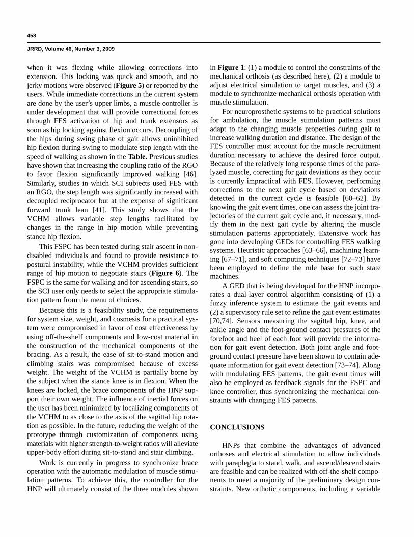
Typical mean ± SD gait parameters are shown in theTable for nondisabled Subject 1 walking at slow, pre-ferred, and fast speeds with the prototype exoskeleton ofthe hybrid neuroprosthesis. An increase in speed is corre-lated with an increase in cadence, step length, and hipexcursion (the angle between the hips at heel strike.)
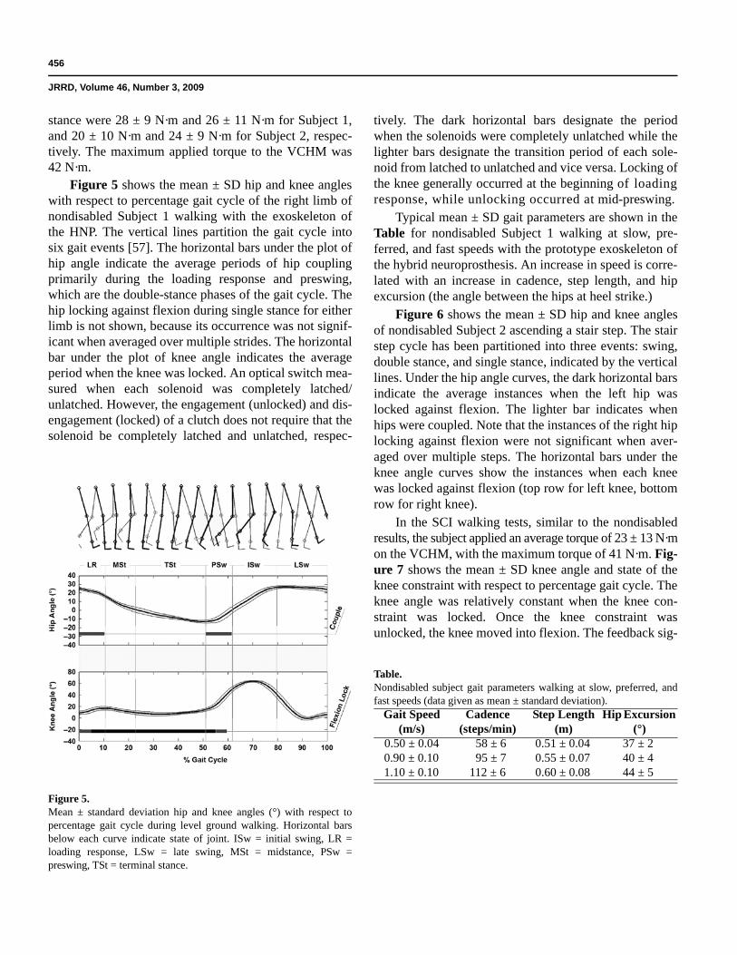
Figure 6 shows the mean ± SD hip and knee anglesof nondisabled Subject 2 ascending a stair step. The stairstep cycle has been partitioned into three events: swing,double stance, and single stance, indicated by the verticallines. Under the hip angle curves, the dark horizontal barsindicate the average instances when the left hip waslocked against flexion. The lighter bar indicates whenhips were coupled. Note that the instances of the right hiplocking against flexion were not significant when aver-aged over multiple steps. The horizontal bars under theknee angle curves show the instances when each kneewas locked against flexion (top row for left knee, bottomrow for right knee).
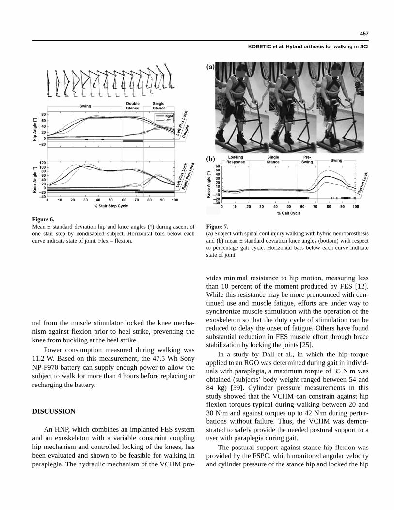
In the SCI walking tests, similar to the nondisabledresults, the subject applied an average torque of 23 ± 13 N·mon the VCHM, with the maximum torque of 41 N·m. Fig-ure 7 shows the mean ± SD knee angle and state of theknee constraint with respect to percentage gait cycle. Theknee angle was relatively constant when the knee con-straint was locked. Once the knee constraint wasunlocked, the knee moved into flexion. The feedback sig-
Figure 5.Mean ± standard deviation hip and knee angles (°) with respect topercentage gait cycle during level ground walking. Horizontal barsbelow each curve indicate state of joint. ISw = initial swing, LR =loading response, LSw = late swing, MSt = midstance, PSw =preswing, TSt = terminal stance.
Table.Nondisabled subject gait parameters walking at slow, preferred, andfast speeds (data given as mean ± standard deviation).
Gait Speed (m/s)
Cadence (steps/min)
Step Length (m)
Hip Excursion (°)
0.50 ± 0.04 58 ± 6 0.51 ± 0.04 37 ± 20.90 ± 0.10 95 ± 7 0.55 ± 0.07 40 ± 41.10 ± 0.10 112 ± 6 0.60 ± 0.08 44 ± 5
457
KOBETIC et al. Hybrid orthosis for walking in SCI
nal from the muscle stimulator locked the knee mecha-nism against flexion prior to heel strike, preventing theknee from buckling at the heel strike.
Power consumption measured during walking was11.2 W. Based on this measurement, the 47.5 Wh SonyNP-F970 battery can supply enough power to allow thesubject to walk for more than 4 hours before replacing orrecharging the battery.
DISCUSSION
An HNP, which combines an implanted FES systemand an exoskeleton with a variable constraint couplinghip mechanism and controlled locking of the knees, hasbeen evaluated and shown to be feasible for walking inparaplegia. The hydraulic mechanism of the VCHM pro-
vides minimal resistance to hip motion, measuring lessthan 10 percent of the moment produced by FES [12].While this resistance may be more pronounced with con-tinued use and muscle fatigue, efforts are under way tosynchronize muscle stimulation with the operation of theexoskeleton so that the duty cycle of stimulation can bereduced to delay the onset of fatigue. Others have foundsubstantial reduction in FES muscle effort through bracestabilization by locking the joints [25].
In a study by Dall et al., in which the hip torqueapplied to an RGO was determined during gait in individ-uals with paraplegia, a maximum torque of 35 N·m wasobtained (subjects’ body weight ranged between 54 and84 kg) [59]. Cylinder pressure measurements in thisstudy showed that the VCHM can constrain against hipflexion torques typical during walking between 20 and30 N·m and against torques up to 42 N·m during pertur-bations without failure. Thus, the VCHM was demon-strated to safely provide the needed postural support to auser with paraplegia during gait.
The postural support against stance hip flexion wasprovided by the FSPC, which monitored angular velocityand cylinder pressure of the stance hip and locked the hip
Figure 6.Mean ± standard deviation hip and knee angles (°) during ascent ofone stair step by nondisabled subject. Horizontal bars below eachcurve indicate state of joint. Flex = flexion.
Figure 7.(a) Subject with spinal cord injury walking with hybrid neuroprosthesisand (b) mean ± standard deviation knee angles (bottom) with respectto percentage gait cycle. Horizontal bars below each curve indicatestate of joint.
458
JRRD, Volume 46, Number 3, 2009
when it was flexing while allowing corrections intoextension. This locking was quick and smooth, and nojerky motions were observed (Figure 5) or reported by theusers. While immediate corrections in the current systemare done by the user’s upper limbs, a muscle controller isunder development that will provide correctional forcesthrough FES activation of hip and trunk extensors assoon as hip locking against flexion occurs. Decoupling ofthe hips during swing phase of gait allows uninhibitedhip flexion during swing to modulate step length with thespeed of walking as shown in the Table. Previous studieshave shown that increasing the coupling ratio of the RGOto favor flexion significantly improved walking [46].Similarly, studies in which SCI subjects used FES withan RGO, the step length was significantly increased withdecoupled reciprocator but at the expense of significantforward trunk lean [41]. This study shows that theVCHM allows variable step lengths facilitated bychanges in the range in hip motion while preventingstance hip flexion.
This FSPC has been tested during stair ascent in non-disabled individuals and found to provide resistance topostural instability, while the VCHM provides sufficientrange of hip motion to negotiate stairs (Figure 6). TheFSPC is the same for walking and for ascending stairs, sothe SCI user only needs to select the appropriate stimula-tion pattern from the menu of choices.
Because this is a feasibility study, the requirementsfor system size, weight, and cosmesis for a practical sys-tem were compromised in favor of cost effectiveness byusing off-the-shelf components and low-cost material inthe construction of the mechanical components of thebracing. As a result, the ease of sit-to-stand motion andclimbing stairs was compromised because of excessweight. The weight of the VCHM is partially borne bythe subject when the stance knee is in flexion. When theknees are locked, the brace components of the HNP sup-port their own weight. The influence of inertial forces onthe user has been minimized by localizing components ofthe VCHM to as close to the axis of the sagittal hip rota-tion as possible. In the future, reducing the weight of theprototype through customization of components usingmaterials with higher strength-to-weight ratios will alleviateupper-body effort during sit-to-stand and stair climbing.
Work is currently in progress to synchronize braceoperation with the automatic modulation of muscle stimu-lation patterns. To achieve this, the controller for theHNP will ultimately consist of the three modules shown
in Figure 1: (1) a module to control the constraints of themechanical orthosis (as described here), (2) a module toadjust electrical simulation to target muscles, and (3) amodule to synchronize mechanical orthosis operation withmuscle stimulation.
For neuroprosthetic systems to be practical solutionsfor ambulation, the muscle stimulation patterns mustadapt to the changing muscle properties during gait toincrease walking duration and distance. The design of theFES controller must account for the muscle recruitmentduration necessary to achieve the desired force output.Because of the relatively long response times of the para-lyzed muscle, correcting for gait deviations as they occuris currently impractical with FES. However, performingcorrections to the next gait cycle based on deviationsdetected in the current cycle is feasible [60–62]. Byknowing the gait event times, one can assess the joint tra-jectories of the current gait cycle and, if necessary, mod-ify them in the next gait cycle by altering the musclestimulation patterns appropriately. Extensive work hasgone into developing GEDs for controlling FES walkingsystems. Heuristic approaches [63–66], machining learn-ing [67–71], and soft computing techniques [72–73] havebeen employed to define the rule base for such statemachines.
A GED that is being developed for the HNP incorpo-rates a dual-layer control algorithm consisting of (1) afuzzy inference system to estimate the gait events and(2) a supervisory rule set to refine the gait event estimates[70,74]. Sensors measuring the sagittal hip, knee, andankle angle and the foot-ground contact pressures of theforefoot and heel of each foot will provide the informa-tion for gait event detection. Both joint angle and foot-ground contact pressure have been shown to contain ade-quate information for gait event detection [73–74]. Alongwith modulating FES patterns, the gait event times willalso be employed as feedback signals for the FSPC andknee controller, thus synchronizing the mechanical con-straints with changing FES patterns.
CONCLUSIONS
HNPs that combine the advantages of advancedorthoses and electrical stimulation to allow individualswith paraplegia to stand, walk, and ascend/descend stairsare feasible and can be realized with off-the-shelf compo-nents to meet a majority of the preliminary design con-straints. New orthotic components, including a variable
459
KOBETIC et al. Hybrid orthosis for walking in SCI
constraint hip mechanism, were designed, prototyped,and successfully tested on nondisabled volunteers and anindividual with SCI. The default, fail-safe mode of opera-tion of the variable constraint hip mechanism is identicalto that of a conventional RGO that couples hip flexion tocontralateral hip extension in a 1:1 ratio. The hydraulicmechanism and control maintain erect posture whileallowing free movement for walking and stair climbing.Because the hybrid was built from off-the-shelf compo-nents to minimize development costs, weight and cosmesisspecifications for clinical use have not been met,although the power requirements are low enough to pro-vide more than 4 hours of continuous operation with twostandard camcorder batteries. Further refinement of themechanism, as well as additional orthotic components forthe trunk, knees, and ankles, remain to be completedbefore the hybrid approach of combining orthotic andelectrical interventions can be practical clinical optionsfor persons with SCI.
ACKNOWLEDGMENTS
Author Contributions:Study concept and design: R. Kobetic, C. S. To, R. Triolo.Acquisition of data: C. S. To, M. Audu.Analysis and interpretation of data: C. S. To, R. Kobetic, M. Audu, S. Tashman.Drafting of manuscript: R. Kobetic, C. S. To.Critical revision of manuscript for important intellectual content: R. Kobetic, C. S. To, R. Triolo.Statistical analysis: C. S. To.Obtained funding: R. Triolo, R. Kobetic.Administrative, technical, or material support: J. Schnellenberger, T. Bulea, G. Pinault, R. Gaudio.Study supervision: R. Kobetic, R. Triolo.Financial Disclosures: The authors have declared that no competing interests exist.Funding/Support: This material is based on work supported in part by the U.S. Department of Veterans Affairs, Rehabilitation Research and Development Service, grant B3463R, and the Department of Defense, Congressionally Directed Medical Research Program, grant PR043074.Additional Contributions: We acknowledge Peter Adamczyk for his initial conception of the hydraulic design for the hip mechanism and Dr. Roger Quinn and his staff and students of the Bio-Robotics Labo-ratory in the Department of Mechanical and Aerospace Engineering at Case Western Reserve University for their advice and collaboration in the development of trunk and ankle mechanisms for the hybrid neuro-prosthesis. Participant Follow-Up: The authors plan to inform participants of the publication of this study.
REFERENCES
1. Merritt JL, Miller NE, Hanson TJ. Preliminary studies ofenergy expenditure in paraplegics using swing through andreciprocal gait patterns. Arch Phys Med Rehabil. 1983;64:510.
2. Winchester PK, Carollo JJ, Parekh RN, Lutz LM, AstonJW Jr. A comparison of paraplegic gait performance usingtwo types of reciprocating gait orthoses. Prosthet OrthotInt. 1993;17(2):101–6. [PMID: 8233765]
3. Hussy RW, Stauffer ES. Spinal cord injury: Requirementsfor ambulation. Arch Phys Med Rehabil. 1973;54(2):544–47.[PMID: 4759444]
4. Moore P, Stallard JS. A clinical review of adult paraplegicpatients with complete lesion using the ORLAU Parawalker.Paraplegia. 1991;29:191–96.
5. Kralj A, Grobelink S, Vodovnik L. Functional electricalstimulation—A new hope for paraplegic patients. BullProsthet Res. 1973;20:73–102.
6. Nene AV, Hermens HJ, Zilvold G. Paraplegic locomotion:A review. Spinal Cord. 1996;34(9):507–24. [PMID: 8883185]
7. Kralj A, Bajd T, Turk R, Krajnik J, Benko H. Gait restora-tion in paraplegic patients: A feasibility demonstrationusing multichannel surface electrode FES. J Rehabil ResDev. 1983;20(1):3–20. [PMID: 6887064]
8. Scheiner A, Polando G, Marsolais EB. Design and clinicalapplication of a double helix electrode for functional elec-trical stimulation. IEEE Trans Biomed Eng. 1994;41(5):425–31. [PMID: 8070801] DOI:10.1109/10.293216
9. Marsolais EB, Kobetic R. Implantation techniques andexperience with percutaneous intramuscular electrodes inthe lower extremities. J Rehabil Res Dev. 1986;23(3):1–8.[PMID: 3490566]
10. Nandurkar S, Marsolais EB, Kobetic R. Percutaneousimplantation of iliopsoas for functional neuromuscularstimulation. Clin Orthop Relat Res. 2001 Aug;(389):210–17.[PMID: 11501813] DOI:10.1097/00003086-200108000-00030
11. Shimada Y, Sato K, Abe E, Kagaya H, Ebata K, Oba M,Sata M. Clinical experience of functional electrical stimu-lation in complete paraplegia. Spinal Cord. 1996;34(10):615–19. [PMID: 8896129]
12. Kobetic R, Marsolais EB. Synthesis of paraplegic gait withmultichannel functional neuromuscular stimulation. IEEETrans Rehabil Eng. 1994;2(2):66–79. DOI:10.1109/86.313148
13. Kobetic R, Triolo RJ, Marsolais EB. Muscle selection andwalking performance of multichannel FES systems forambulation in paraplegia. IEEE Trans Rehabil Eng. 1997;5(1):23–29. [PMID: 9086382] DOI:10.1109/86.559346
460
JRRD, Volume 46, Number 3, 2009
14. Holle J, Frey M, Gruber H, Kern H, Stohr H, Thoma H.Functional electrostimulation of paraplegics: Experimentalinvestigations and first clinical experience with an implant-able stimulation device. Orthopedics. 1984;7(7):1145–60.
15. Brindley GS, Polkey CE, Rushton DN. Electrical splintingof the knee in paraplegia. Paraplegia. 1979;16(4):428–37.[PMID: 311910]
16. Kobetic R, Triolo RJ, Uhlir JP, Bieri C, Wibowo M,Polando G, Marsolais EB, Davis JA Jr, Ferguson KA.Implanted functional electrical stimulation system formobility in paraplegia: A follow-up case report. IEEETrans Rehabil Eng. 1999;7(4):390–98. [PMID: 10609626] DOI:10.1109/86.808942
17. Von Wild K, Rabischong P, Brunelli G, Benichou M, Krish-nan K. Computer added locomotion by implanted electricstimulation in paraplegic patients (SUAW). Acta NeurochirSuppl. 2001;79:99–104. [PMID: 11974998]
18. Guiraud D, Stieglitz T, Koch KP, Divoux JL, Rabischong P.An implantable neuroprosthesis for standing and walkingin paraplegia: 5-year patient follow-up. J Neural Eng. 2006;3(4):268–75. [PMID: 17124330]DOI:10.1088/1741-2560/3/4/003
19. Graupe D, Kohn KH, Kralj A, Basseas S. Patient controlledelectrical stimulation via EMG signature discrimination forproviding certain paraplegics with primitive walking func-tions. J Biomed Eng. 1983;5(3):220–26. [PMID: 6887824]DOI:10.1016/0141-5425(83)90100-0
20. Marsolais EB, Edwards BG. Energy costs of walking andstanding with functional neuromuscular stimulation and longleg braces. Arch Phys Med Rehabil. 1988;69(4):243–49.[PMID: 3258509]
21. Brissot R, Gallien P, Le Bot MP, Beaubras A, Laisné D,Beillot J, Dassonville J. Clinical experience with functionalelectrical stimulation-assisted gait with Parastep in spinalcord patients. Spine. 2000;25(4):501–8. [PMID: 10707398]DOI:10.1097/00007632-200002150-00018
22. Agarwal S, Kobetic R, Nandurkar S, Marsolais EB. Func-tional electrical stimulation for walking in paraplegia: 17-year follow-up of 2 cases. J Spinal Cord Med. 2003;26(1):86–91. [PMID: 12830975]
23. Tomovic R, Vukobratovic M, Vodovnik L. Hybrid actuatorsfor orthotic systems: Hybrid assistive systems. In: PopovicD, editor. Advances in external control on human extremi-ties. Proceedings I–X of the Fourth International Sympo-sium on External Control of Human Extremities; 1972 Aug28–Sep 2: Dubrovnik, Yugoslavia. Aalborg (Denmark):Center for Sensory–Motion Interaction; 1972.
24. Goldfarb M, Durfee W. Design of a controlled-brake orthosisfor FES-aided gait. IEEE Trans Rehabil Eng. 1996;4(1):13–24. [PMID: 8798068] DOI:10.1109/86.486053
25. Goldfarb M, Korkowski K, Harrold B, Durfee W. Prelimi-nary evaluation of a controlled-brake orthosis for FES-aided gait. IEEE Trans Neural Syst Rehabil Eng. 2003;11(3):241–48. [PMID: 14518787] DOI:10.1109/TNSRE.2003.816873
26. Greene PJ, Granat MH. A knee and ankle flexing hybridorthosis for paraplegic ambulation. Med Eng Phys. 2003;25(7):539–45. [PMID: 12835066] DOI:10.1016/S1350-4533(03)00072-9
27. Gharooni S, Heller B, Tokhi MO. A new hybrid springbrake orthosis for controlling hip and knee flexion in theswing phase. IEEE Trans Neural Syst Rehabil Eng. 2001;9(1):106–7. [PMID: 11482357] DOI:10.1109/7333.918283
28. Durfee WK, Rivard A. Design and simulation of a pneu-matic, stored-energy, hybrid orthosis for gait restoration.J Biomech Eng. 2005;127(6):1014–19. [PMID: 16438242] DOI:10.1115/1.2050652
29. Patrick JH, McClelland MR. Low energy cost reciprocalwalking for the adult paraplegic. Paraplegia. 1985;23(2):113–17. [PMID: 4000691]
30. Stallard J, Major RE, Poiner R, Farmer IR, Jones N. Engi-neering design considerations of the ORLAU Parawalkerand FES hybrid system. Eng Med. 1986;15(3):123–29.[PMID: 3743854] DOI:10.1243/EMED_JOUR_1986_015_034_02
31. McClelland M, Andrews BJ, Patrick JH, Freeman PA, ElMasri WS. Augmentation of the Oswestry ParawalkerOrthosis by means of surface electrical stimulation: Gaitanalysis of three patients. Paraplegia. 1987;25(1):32–38.[PMID: 3562054]
32. Nene AV, Patrick JH. Energy cost of paraplegic locomotionusing the ParaWalker—Electrical stimulation “hybrid”orthosis. Arch Phys Med Rehabil. 1990;71(2):116–20.[PMID: 2302043]
33. Phillips CA, Hendershot DM. A systems approach to medi-cally prescribed functional electrical stimulation. Ambulationafter spinal cord injury. Paraplegia. 1991;29(8):505–13.[PMID: 1775356]
34. Isakov E, Douglas R, Berns P. Ambulation using the recip-rocating gait orthosis and functional electrical stimulation.Paraplegia. 1992;30(4):239–45. [PMID: 1625891]
35. Yang L, Granat MH, Paul JP, Condie DN, Rowley DI. Fur-ther development of hybrid functional electrical stimulationorthoses. Spinal Cord. 1996;34(10):611–14. [PMID: 8896128]
36. Solomonow M, Aguilar E, Reisin E, Baratta RV, Best R,Coetzee T, D’Ambrosia R. Reciprocating gait orthosispowered with electrical muscle stimulation (RGO II). Part I:Performance evaluation of 70 paraplegic patients. Orthope-dics. 1997;20(4):315–24. [PMID: 9127865]
461
KOBETIC et al. Hybrid orthosis for walking in SCI
37. Petrofsky JS, Phillips CA, Douglas R, Larson P. A computer-controlled walking system: The combination of an orthosiswith functional electrical stimulation. J Clin Eng. 1986;11(2):121–33.
38. Solomonow M, Baratta R, Hirokawa S, Rightor N, WalkerW, Beaudette P, Shoji H, D’Ambrosia R. The RGO Genera-tion II: Muscle stimulation powered orthosis as a practicalwalking system for thoracic paraplegics. Orthopedics. 1980;12(10):1309–15. [PMID: 2798239]
39. Nene AV, Jennings SJ. Hybrid paraplegic locomotion withthe ParaWalker using intramuscular stimulation: A singlesubject study. Paraplegia. 1989;27(2):125–32. [PMID: 2785668]
40. Marsolais EB, Kobetic R, Polando G, Ferguson K, Tash-man S, Gaudio R, Nandurkar S, Lehneis HR. The CaseWestern Reserve University hybrid gait orthosis. J SpinalCord Med. 2000;23(2):100–108. [PMID: 10914350]
41. Kobetic R, Marsolais EB, Triolo RJ, Davy DT, Gaudio R,Tashman S. Development of a hybrid gait orthosis: A casereport. J Spinal Cord Med. 2003;26(3):254–58. [PMID: 14997968]
42. Hirokawa S, Grimm M, Le T, Solomonow M, Baratta RV,Shoji H, D’Ambrosia RD. Energy consumption in paraple-gic ambulation using the reciprocating gait orthosis andelectrical stimulation of the thigh muscles. Arch Phys MedRehabil. 1990;71(9):687–94. [PMID: 2375676]
43. McClelland M, Andrews BJ, Patrick JH, Freeman PA, ElMasri WS. Augmentation of the Oswestry Parawalkerorthosis by means of surface electrical stimulation: Gaitanalysis of three patients. Paraplegia. 1987;25(1):32–38.[PMID: 3562054]
44. Stallard J, Major RE. The influence of orthosis stiffness onparaplegic ambulation and its implications for functionalelectrical stimulation (FES) walking systems. ProsthetOrthot Int. 1995;19(2):108–14. [PMID: 8570380]
45. Petrofsky JS, Smith JB. Physiologic costs of computer-controller walking in persons with paraplegia using areciprocating-gait orthosis. Arch Phys Med Rehabil. 1991;72(11):890–96. [PMID: 1929807] DOI:10.1016/0003-9993(91)90007-6
46. Yang L, Granat MH, Paul JP, Condie ND, Rowley DI. Fur-ther development of hybrid functional electrical stimula-tion orthoses. Spinal Cord. 1996;34(10):611–14. [PMID: 8896128]
47. Kagaya H, Shimada Y, Sato K, Sato M, Iizuka K, ObinataG. An electrical knee lock system for functional electricalstimulation. Arch Phys Med Rehabil. 1996;77(9):870–73.[PMID: 8822676] DOI:10.1016/S0003-9993(96)90272-5
48. Jaspers P, Van Petegem W, Van der Perre G, Peeraer L.Optimisation of a combined ARGO-FES system: adapta-tion of the knee mechanism to allow flexion of the knee
during the swing phase. In: Proceedings of the 17th AnnualInternational Conference of the IEEE Vol. 2; 1995 Sep 20–23; Montreal, Canada. Montreal (Canada): Engineering inMedicine and Biology Society; 1995. p. 1143–44.
49. Harrison R, Lemaire E, Jeffreys Y, Goudreau L. Design andpilot testing of an orthotic stance-phase control knee joint.Orthopädie-Technik Quarterly, English edition. 2001;3:2–4.
50. NASA Office of Aeronautics. Quicker rehabilitation fornew knee brace wearers. Aerosp Technol Innov. 1997:5(1):8.
51. McMillan AG, Kendrick K, Michael JW, Aronson J, Hor-ton GW. Preliminary evidence for effectiveness of a StanceControl Orthosis. J Prosthetics and Orthotics. 2004;16(1):6–13.
52. Myers NW, Shadoan MD, Forbes JC, Baker KJ, Rice DC,inventors; the United States of America as represented bythe Administrator, assignee. Selectively lockable knee brace.United States patent US 5490831. 1996 Feb 13.
53. Irby SE, Kaufman KR, Wirta RW, Sutherland DH. Optimi-zation and application of a wrap-spring clutch to a dynamicknee-ankle-foot orthosis. IEEE Trans Rehabil Eng. 1999;7(2):130–34. [PMID: 10391582] DOI:10.1109/86.769402
54. Irby SE, Kaufman KR, Mathewson JW, Sutherland DH.Automatic control design for a dynamic knee-brace system.IEEE Trans Rehabil Eng. 1999;7(2):135–39. [PMID: 10391583] DOI:10.1109/86.769403
55. To CS, Kobetic R, Schnellenberger JR, Audu ML, TrioloRJ. Design of a variable constraint hip mechanism for ahybrid neuroprosthesis to restore gait after spinal cord injury.IEEE/ASME Trans Mechatronics. 2008;13(2):197–205.
56. To CS, Kobetic R, Triolo RJ. Design of a finite statemachine for the variable constraint hip mechanism to pro-vide postural stability during gait after spinal cord injury.In: Proceedings of the 4th International Symposium onAdaptive Motion of Animals and Machines; 2008 Jun 1–8;Cleveland, Ohio. p. 148–49.
57. Perry J. Gait analysis: Normal and pathological function.Thorofare (NJ): SLACK Inc; 1992. p. 120,246.
58. Krawetz P, Nance P. Gait analysis of spinal cord injuredsubjects: Effects of injury level and spasticity. Arch PhysMed Rehabil. 1996:77(7):635–38. [PMID: 8669987]DOI:10.1016/S0003-9993(96)90000-3
59. Dall PM, Müller B, Stallard I, Edwards J, Granat MH. Thefunctional use of the reciprocal hip mechanism during gaitfor paraplegic patients walking in the Louisiana StateUniversity reciprocating gait orthosis. Prosthet Orthot Int.1999; 23(2):152–62. [PMID: 10493143]
60. Franken HM, Veltink PH, Baardman G, Redmeyer RA,Boom HB. Cycle-to-cycle control of swing phase of para-plegic gait induced by surface electrical stimulation. Med
462
JRRD, Volume 46, Number 3, 2009
Biol Eng Comput. 1995;33(3 Spec No):440–51.[PMID: 7666692]
61. Veltink PH. Control of FES-induced cyclical movements ofthe lower leg. Med Biol Eng Comput. 1991;29(6):NS8–NS12. [PMID: 1813749] DOI:10.1007/BF02446096
62. Franken HM, Veltink PH, Baardman G, Redmeijer RA,Boom HB. Experimental on/off control of the swing phaseof paraplegic gait induced by surface electrical stimulation.In: Proceedings of the 15th Annual Conference of theIEEE; Engineering in Medicine and Biology Society; 1993Oct 28–31; San Diego, California. p. 1324–25.
63. Franken HM, DeVries W, Veltink PH, Baardman G, BoomHB. State detection during paraplegic gait as part of a finitestate based controller. In: Proceedings of the 15th AnnualConference of the IEEE Engineering in Medicine and BiologySociety; 1993 Oct 28–31; San Diego, California. p. 1322–23.
64. Andrews BJ, Barnett RW, Phillips GF, Kirkwood CA,Donaldson N, Rushton DN, Perkins DA. Rule-based con-trol of a hybrid FES orthosis for assisting paraplegic loco-motion. Automedica. 1989;11:175–99.
65. Willemsen AT, Bloemhof F, Boom HB. Automatic stance-swing phase detection from accelerometer data for pero-neal nerve stimulation. IEEE Trans Biomed Eng. 1990:37(12):1201–8. [PMID: 2289794] DOI:10.1109/10.64463
66. Pappas IP, Popovic MR, Keller T, Dietz V, Morari M. Areliable gait phase detection system. IEEE Trans NeuralSyst Rehabil Eng. 2001;9(2):113–25. [PMID: 11474964]DOI:10.1109/7333.928571
67. Kirkwood CA, Andrews BJ. Finite state control of FESsystems: Application of AI inductive learning techniques.In: Proceedings of the Eleventh Annual Conference of theIEEE Engineering in Medicine and Biology Society; 1989Nov 9–12; Seattle, Washington. p. 1020–21.
68. Nikolic ZM, Popovic DB. Automatic rule determinationfor finite state model of locomotion. In: Proceedings of the16th Annual Conference of the IEEE Engineering in Medi-cine and Biology Society; 1991 Sep 20–25; Baltimore,Maryland. p. 1382–83.
69. Kostov A, Andrews BJ, Popovi DB, Stein RB, ArmstrongWW. Machine learning in control of functional electricalstimulation systems for locomotion. IEEE Trans BiomedEng. 1995;42(6):541–51. [PMID: 7790010] DOI:10.1109/10.387193
70. Williamson R, Andrews BJ. Gait event detection for FESusing accelerometers and supervised machine learning.IEEE Trans Rehabil Eng. 2000;8(3):312–19. [PMID: 11001511] DOI:10.1109/86.867873
71. Hansen M, Haugland MK, Sinkjaer T. Evaluating robust-ness of gait event detection based on machine learning andnatural sensors. IEEE Trans Neural Syst Rehabil Eng.2004;12(1):81–88. [PMID: 15068191] DOI:10.1109/TNSRE.2003.819890
72. Ng SK, Chizeck HJ. A fuzzy logic gait event detector forFES paraplegic gait. In: Proceedings of the 15th AnnualConference of the IEEE Engineering in Medicine and BiologySociety; 1993 Oct 28–31; San Diego, California. p. 1238–39.
73. Ng SK, Chizeck HJ. Fuzzy model identification for classi-fication of gait events in paraplegics. IEEE Trans FuzzySyst. 1997;5:536–44. DOI:10.1109/91.649904
74. Skelly MM, Chizeck HJ. Real-time gait event detection forparaplegic FES walking. IEEE Trans Neural Syst RehabilEng. 2001;9(1):59–68. [PMID: 11482364] DOI:10.1109/7333.918277
Submitted for publication July 28, 2008. Accepted inrevised form January 13, 2009.