Embed Size (px)
Citation preview

DEVELOPMENT of INDUCTION SURFACE HARDENING PROCESS for SMALL DIAMETER CARBON STEEL SPECIMENS
Daisuke Suzuki, Koji Yatsushiro, Seiji Shimizu (1), Yoshio Sugita (2), Motoki Saito (3), Katsuhiko Kubota(4)
(1) Yamanashi Industrial Technology Center (2) YS Electronics Co., LTD.
(3) ASAKAWA HEAT TREATMENT Co., LTD. (4) Marushin Heat Treatment Co., LTD.
ABSTRACT In case of induction hardening, the highly frequency generator make a shallow hardened zone. Additionally, hardening for smaller diameter specimen is enabled. In this study, the induction surface hardening process by the ultra high frequency generator of 2MHz, which had not used in the general conventional process, was developed. The specimen (6mm in diameter) was hardened using our developed device, under various conditions of generator voltage and specimen moving speed. Quenched specimens were evaluated by measuring residual stress distribution, cross-section observation, hardness distribution and distortion. As a result, one of heat treatment condition brought a good result; the depth of hardened zone was about 0.4mm, and the hardness was about 600HV near the surface. The deeper hardened zone specimens had compressive residual stress about �500MPa in the longitudinal direction at the surface. Moreover, it was decreased slightly from surface to center. However, in the hoop direction, compressive residual stress was about 0MPa. This anisotropy was caused large thermal stress, which was compared with the present induction hardening. Furthermore, the best result in 3mm diameter specimen had very shallow hardened zone that depth was about 0.09mm, and hardness was about 600HV near the surface.
INTRODUCTION In recent years, downsizing of machine and electronic device is in process. And these components are using small parts. This reason is necessary for develop of competitive and high-value added products. In the past, bulk heat treatment such as continuous quenching had used for these small components. But this heat treatment method required a long time for rising temperature, and it causes the distortion of heat treatment objects. On the other hand, induction hardening is effective solution to these defects. Characteristic of this method can be rapid, surface, and direct heating. Also, this method can do the addition of the high compressive residual stress on surface, improvement of fatigue strength, and restraint of distortion, which was compared to other bulk heat treatment methods [1]. Therefore, it has used for the shafts, gears, crankshafts, and others.
569Copyright ©JCPDS-International Centre for Diffraction Data 2009 ISSN 1097-0002Advances in X-ray Analysis, Volume 52

This document was presented at the Denver X-ray Conference (DXC) on Applications of X-ray Analysis. Sponsored by the International Centre for Diffraction Data (ICDD). This document is provided by ICDD in cooperation with the authors and presenters of the DXC for the express purpose of educating the scientific community. All copyrights for the document are retained by ICDD. Usage is restricted for the purposes of education and scientific research. DXC Website – www.dxcicdd.com
ICDD Website - www.icdd.com
Advances in X-ray Analysis, Volume 52

However, the existing induction hardening was not used for the heat treatment of small components. Because heating was not efficient for small components, and fever depth become deep, which follows similar to bulk heat treatment. The purpose of this study is reducing distortion, and providing the compressive residual stress for the small diameter carbon steel surface by induction surface hardening. First, the surface heat treatment device was developed using a 2MHz ultra high frequency generator [2], which was not in common use. It can do the very rapid, and superficial heating is its characteristic. Next, heat treatment applied for 6mm and 3mm in diameter carbon steel rod specimens. Quenched specimens were evaluated by measuring cross-section, hardness distribution observation (6mm and 3mm in diameter specimens), residual stress and distortion (6mm in diameter specimen). EXAMINATION Specimens The material of specimen was C45 (ISO, JIS; S45C). The specimen diameter was 6mm and its length was 100mm. And any heat treatment was not done before induction hardening. Table.1 shows heat treatment conditions. The specimens (a) from (e) were quenched by induction hardening under various conditions of voltage and specimen moving speed. The status of specimen (f) was full quenched, specimen (g) was annealed, and specimen (h) was as received. These specimens were prepared for comparison to induction hardening. Quenched specimens were evaluated by cross section observation, hardness distribution, residual stress, and distortion. Prototype heat treatment device Fig.1 shows overview of the prototype induction heat treatment device. This device is made up four sections as Fig.1. And Fig.2 shows a schematic view of the prototype induction heat treatment device; (a) specimen, (b) heating coil, (c) water jacket for cooling, (d) was specimen moving and hold device.
Table.1 Specimen and heat treatment condition
Specimen Heat treatment method Heat treatment condition
(a)
Induction hardening
265V-20.6mm/s
(b) 265V-31.8mm/s Rotating speed : 30 r/s
(c) 265V-38.9mm/s Cooling method : Water cooled
(d) 265V-50.0mm/s Quench length : 70 mm
(e) 230V-20.6mm/s
(f) Dip quenching (Furnace heating)
Quenching:1133K×7.2ks Tempering:453K×7.2ks
(g) Annealing (Furnace cooling) 873K×7.2ks (Nitrogen atmosphere)
(h) As received -
570Copyright ©JCPDS-International Centre for Diffraction Data 2009 ISSN 1097-0002Advances in X-ray Analysis, Volume 52

fd
500
(f was the generator frequency: Hz)
(mm) (1)
In case of general steel materials, hardened depth of induction hardening was calculated from empirical equation (1) [3]. In this study, generator frequency of prototype device was used 2MHz. Then, hardened depth was calculated as approximately 0.35mm. Measurement of residual stress Table.2 shows conditions of X-ray stress measurement, and the measurement position is shown in Fig.3. The measurement instrument was RIGAKU MSF-2M. Measurement method was fixed ø with parallel beam splitter. Residual
stress was measured in the longitudinal and the hoop direction. The measurement area was 2 x 4 mm. The residual stress distribution of the depth direction was measured by electrolytic polishing. In addition, the relocation of the residual stress by electrolytic polishing was not considered. Evaluation of distortion The distortion were evaluated by the axial-runout Z, the changes of specimen overall length ål, and the changes of specimen length åd. The distortions were calculated by the formulas (2), (3), and (4). The measurement method of axial-runout was as follows; the specimen was supported by V-blocks at both ends. And axial runout was read off the value of dial gauge, when specimen was turning. The quenched length was not equal between full quenched specimen and induction
Table.2 Conditions of X-ray stress measurement
Diffraction áFe211 Target Cr
Tube voltage 30kV Filament current 8mA
Measurement method Fixed Ø Stress constant -297MPa/deg
Fig.1 Overview of the prototype heat treatment device
←a
←c
b ↓
↑ d
High frequency
generator
Power control device
a: Specimen b: Heating coil c: Water jacket d: Specimen hold and moving device
Fig.2 Schematic view of the prototype heat treatment device
ö6
10mm
Measured position
Fig.3 Measured position of residual stress
0
01
å
l
lll
(2)
0
01
å
d
ddd
(3)
0
01
l
ZZZ
(4)
571Copyright ©JCPDS-International Centre for Diffraction Data 2009 ISSN 1097-0002Advances in X-ray Analysis, Volume 52

hardening specimens. But here, changes of specimen overall length ål, and the axial-runout Z were evaluated by same method. Additionally, measured value was evaluated in average of ten specimens about every heat treatment conditions. RESULT Result of cross section observation (6mm in diameter) Fig.4 and Fig.5 are result of cross-section observation and hardness distribution. The specimen (a) had the deepest hardened zone in induction hardening, which depth was about 0.8mm and hardness was about 700HV near the surface. Then, specimen-moving speed became increasing, the hardening zone depth and hardness value became decreasing. Also, hardened zone depth and hardness became decrease in lower voltage, which was 230V.
Result of distortion Fig.6 shows result of the axial-runout Z measurement. The as received specimen (h) had small amount axial-runout. Axial-runout of annealed specimen (g) was increased a little. And full quenched specimen (f) had 25 times increased axial-runout, which comparison before the heat treatment specimen. In case of induction hardening, specimen (a) had large amount axial-runout and its measured values were varied. This result was like to specimen (f). The distortion of specimen (c) and (e) indicated same tendency of specimen (g) and (h). Fig.7 and Fig.8 show result about changes of specimen length and diameter. In the full quenched specimen (f), overall length was increased 0.13%, and diameter was increased 0.05%. This deformation was due to cubical expansion of martensitic transformation. In the annealed specimen (g), overall length and diameter were decreased a little. This phenomenon was depended on stress release from base material by annealing. On the other hand, the specimen (a) had large distortion at overall length and diameter. However, it was less than half value when it compared with full quenched specimen (f).
Fig.4 Cross section observation of 6mm in diameter
200
300
400
500
600
700
800
0.0 0.2 0.4 0.6 0.8 1.0
specimen(a)
specimen(b)
specimen(c)
specimen(d)
specimen(e)
Distance from surface to center x, (mm)
Vic
kers
Har
dnes
s, (
HV
0.0
5)
Fig.5 Distribution of Vickers hardness from surface to center
572Copyright ©JCPDS-International Centre for Diffraction Data 2009 ISSN 1097-0002Advances in X-ray Analysis, Volume 52
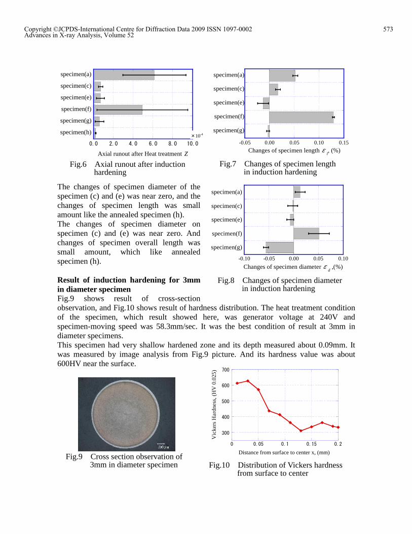
The changes of specimen diameter of the specimen (c) and (e) was near zero, and the changes of specimen length was small amount like the annealed specimen (h). The changes of specimen diameter on specimen (c) and (e) was near zero. And changes of specimen overall length was small amount, which like annealed specimen (h). Result of induction hardening for 3mm in diameter specimen Fig.9 shows result of cross-section observation, and Fig.10 shows result of hardness distribution. The heat treatment condition of the specimen, which result showed here, was generator voltage at 240V and specimen-moving speed was 58.3mm/sec. It was the best condition of result at 3mm in diameter specimens. This specimen had very shallow hardened zone and its depth measured about 0.09mm. It was measured by image analysis from Fig.9 picture. And its hardness value was about 600HV near the surface.
0.0 2.0 4.0 6.0 8.0 10.0
specimen(a)
specimen(c)
specimen(e)
specimen(f)
specimen(g)
specimen(h)×10-4
Axial runout after Heat treatment Z
Fig.6 Axial runout after induction hardening
Fig.7 Changes of specimen length in induction hardening
-0.05 0.00 0.05 0.10 0.15
specimen(a)
specimen(c)
specimen(e)
specimen(f)
specimen(g)
Changes of specimen length ål, (%)
Fig.8 Changes of specimen diameter in induction hardening
-0.10 -0.05 0.00 0.05 0.10
specimen(a)
specimen(c)
specimen(e)
specimen(f)
specimen(g)
Changes of specimen diameter åd ,(%)
Fig.9 Cross section observation of 3mm in diameter specimen Fig.10 Distribution of Vickers hardness
from surface to center
300
400
500
600
700
0 0.05 0.1 0.15 0.2
Distance from surface to center x, (mm)
Vic
kers
Har
dnes
s, (
HV
0.0
25)
573Copyright ©JCPDS-International Centre for Diffraction Data 2009 ISSN 1097-0002Advances in X-ray Analysis, Volume 52

Result of residual stress measurement Fig.11 and Fig.12 show the result of residual stress distribution measurement in longitudinal and hoop direction. In the longitudinal direction, specimen (a) and (e) had bout �500MPa at the specimen surface. And it decreased slightly from surface to center. On the other hand, specimen (b), (c), and (d) had about �200MPa at the specimen surface. It turned to tensile between boundary of hardened zone and base material. Then, measured depth was deepened, and it converged in a zero. It was thought that its tensile residual stress came from the original material. Because specimen-moving speed was very fast, the specimen inside temperature was not enough to reach annealing temperature. Therefore, there was tensile stress from original material, which was formed at the drawing process. However, in the hoop direction, residual stress was close to 0MPa at each specimen. As a result, there is anisotropic residual stress became clear. Thus, half-value breadth was measured to clarify this phenomenon. Fig.13 and Fig.14 show the half-value breadth distribution of diffraction peaks, which was from X-ray stress measurement in the longitudinal and hoop direction. The half-value
1.0
2.0
3.0
4.0
5.0
6.0
7.0
8.0
0.0 0.2 0.4 0.6 0.8 1.0 1.2 1.4
specimen(a)
specimen(b)
specimen(c)
specimen(d)
specimen(e)
Hal
f-va
lue
brea
dth
Hw
L, (
deg)
Distance from surface to center x, (mm)
Fig.13 Distribution of half-value breadth in the longitudinal direction
1.0
2.0
3.0
4.0
5.0
6.0
7.0
8.0
0.0 0.2 0.4 0.6 0.8 1.0 1.2 1.4
specimen(a)
specimen(b)
specimen(c)
specimen(d)
specimen(e)
Hal
f-va
lue
brea
dth
Hw
H, (
deg)
Distance from sufrace to center x, (mm)
Fig.14 Distribution of half-value breadth in the hoop direction
Fig.11 Distribution of residual stress in the longitudinal direction
-800
-600
-400
-200
0
200
0.0 0.2 0.4 0.6 0.8 1.0 1.2 1.4
specimen(a)
specimen(b)
specimen(c)
specimen(d)
specimen(e)
Distance from surface to center x, (mm)
Res
idua
l str
ess ó
A, (
MPa
)
-800
-600
-400
-200
0
200
0.0 0.2 0.4 0.6 0.8 1.0 1.2 1.4
specimen(a)
specimen(b)
specimen(c)
specimen(d)
specimen(e)
Distance from surface to center x, (mm)
Res
idua
l str
ess ó
H, (
MP
a)
Fig.12 Distribution of residual stress in the hoop direction
574Copyright ©JCPDS-International Centre for Diffraction Data 2009 ISSN 1097-0002Advances in X-ray Analysis, Volume 52

breadth of the specimen (a) and (e) were about 6.0, specimen (b), (c), and (d) were about 3.5 at near the surface. And these were decreased from surface to center. And the depth of half-value breadth was same as hardened zone depth. It shows martensitic transformation was confirmed in the longitudinal and hoop direction. Therefore, martensitic transformation was not a factor to form the compressive residual stress in hoop direction. Fig.15 shows schematic description of thermal distribution in induction hardening. In the induction hardening, there is a temperature difference between specimen surface and inside. And this difference brings thermal stress for heating zone. Therefore, the compressive thermal stress was appeared both longitudinal and hoop direction at the surface. Also, the tensile thermal stress was appeared at underneath surface [4]. At this point in time, the compressive thermal stress is reached to plastic deformation start point, it brings the tensile residual stress at the surface, and compressive residual stress at underneath surface after cooling. In this study, the ultra high frequency generator was used for developed device. Thus, heating zone becomes very slight, and it was thought that causes large thermal stress in the heating zone. Here, we defined three-zone (A), (B), and (C) for simplify the explanation of stress behavior. Fig.16 shows schematic description of thermal and martensitic transformation stress in induction hardening. This device was adopted the progressive hardening for heat treatment. And there is the cooling device just below the heating coil. Therefore, there are two zones at hardening process, which are heating zone (A), and cooling zone (B). Moreover, martensitic transformation is occurred when the heat treatment was progressing and reaching to cooling process. This zone named (C). Specimen was moved sequentially from
Zone (A) (Heating)
Zone (B) (Cooling)
Zone (C) (Transformation)
óA1
óH1
óA3
óH3
óA2
óH2
Fig.16 Schematic description of thermal and transformation stress in induction hardening
Zone (A) (Heating)
Specimen surface
Heating head
Heating Coil
Water jacket
Coolant water
Moving direction
Start point of martensitic transformation
Zone (B) (Cooling)
Zone (C) (Transformation)
Fig.15 Schematic description of thermal distribution in induction hardening
575Copyright ©JCPDS-International Centre for Diffraction Data 2009 ISSN 1097-0002Advances in X-ray Analysis, Volume 52

zone (A) to (C). In this figure, the arrows show each zone�s stress directions. First, the zone
(A) has the compressive thermal stresses óA1 and óH1. Secondly, the zone (B) has tensile thermal stresses óA2 and óH2. And the zone (C) has the compressive transformation stresses óA3 and óH3, which from the martensitic transformation. Additionally, these stresses were meant just on surface. Here, we considered effect of stresses; óA1 and óA2, óH1 and óH2, at the boundary of zone (A) and (B). In the longitudinal direction, óA1 was same direction as óA2. So óA1 was possibly absorbed by óA2 at this boundary. However, in the hoop direction, óH1 was overlapped with óH2, because these were different direction. Thereafter, the specimen had a little or near zero tensile stress on the longitudinal direction at the boundary of the zone (B) and (C). On the other hand, it had large tensile stress on the hoop direction at this place. Therefore, it was thought that there was anisotropy of residual stress, which caused by thermal tensile stress, at the boundary of the zone (B) and (C). At the zone (C), óA3 and óH3 was generated from martensitic transformation. In longitudinal direction, óA3 was not affected to tensile stress from the zone (A) and (B), because it thought that was very small. As a result, it was thought that the compressive residual stress was formed in the longitudinal direction. On the other hand, óH3 was countered by tensile residual stress from the zone (A) and (B) in the hoop direction. We thought that is a reason why was not possibly formed residual stress in hoop direction. CONCLUSION The induction hardening was applied to small diameter carbon steel specimens. The results were as follows: 1. Result of heat treatment for 6mm in diameter specimens, the hardened zone depth was
about 0.4mm and hardness value was about 600HV near the surface, we got. 2. The specimens, which hardened zone was large, had compressive residual stress was
about �500MPa. Also, the specimens, which hardened zone was shallow, had compressive residual stress was about �200MPa.
3. In the hoop direction, it turned out that residual stress was not formed by induction hardening of this study.
4. The distortion of large hardened zone specimen was similar to full quenched specimen. And the distortion of shallow hardened zone specimens, it showed similar tendency of annealed or as-received specimen.
5. The best result of heat treatment on 3mm in diameter specimen, its hardened zone was about 0.09mm and hardness value was about 600HV.
[1] The Japan Society for Heat Treatment / Japan Metal Heat Treatment Association, �Netushori-gijutu-nyumon�, pp.272 -275, (1997), Taiga-shuppan (In Japanese) [2] Yoshio Sugita, �Development of ATC(Auto Tool Changer) system by Shrink Fit
method, Die & Mould Technology, Vol.19, No.8, pp.150-151, (2004) (In Japanese) [3] Shigeo Owaku, �Netushori-gijutu-manyuaru�, Japanese Standards Association (In Japanese) [4] Ryozo Isomura, �Hagane-no-netsu-shori-to-zanryu-oryoku�, pp.91-100, (1996), AGNE Gijutsu Center (In Japanese)
576Copyright ©JCPDS-International Centre for Diffraction Data 2009 ISSN 1097-0002Advances in X-ray Analysis, Volume 52