Embed Size (px)
Citation preview
594-2015 heat processing
Induction Technology REPORTS
Procedural aspects of induction hardening
by Stefan Dappen, Farsad Amiri
For increasing the vibration and torsion resistance as well as for improved wear resistance of highly stressed steel and cast components, induction hardening is widely-used. This article gives the reader an understanding of several procedural aspects of induction hardening from practical experiences, which frequently play a decisive role when it comes to the coordination of hardening requirements on the one hand and their conversion into process requirements on the other.
Induction hardening is generally employed for surface hardening, as the current induced during this process is concentrated directly under the surface of the work-
piece due to the “skin effect”. The surface hardening depth can be influenced to a certain extent, depending on the choice of parameters. In many components subject to high dynamic stress, the limitation of the hardening to the surface layer is actually desirable, because maintaining the ductility of the base material is crucial for the fracture strength. Surface hardening also offers the benefit, how-ever, that an appropriate tool and process design allows a near-contour hardening pattern to be created. When using suitable material with adequate serial variance, induction hardening demonstrably provides highly reproducible results after determination of the optimum setting. Fur-thermore, appropriate parameter monitoring systems in hardening machines safeguard the process and can react to a possible drift even within a single cycle. This is a further benefit of induction hardening compared with processes such as furnace or case hardening, as each workpiece is hardened individually and is subject to process control. In the case of critical components, the process parameters for each individual workpiece are recorded and documented for traceability reasons. In some cases the traceability also demands the correlation of the respective workpiece to the process channel used and its specific tool.
WHEN IS INDUCTION HARDENING OF INTEREST?Induction hardening is fundamentally suitable for medi-um-sized and large lots due to the comparatively high process speed on the one hand, and the necessary invest-ment volume on the other. With fully automated machine
concepts, for example, cycle times of approx. 30 s for car crankshafts and approx. 13 s for various axle components (tripods, flanges, axle journals, etc.) are achieved. The actual process time depends on the drawing specifica-tions of the hardening zone as well as on selected process strategy for achieving these drawing specifications. This is of significance as rapid microstructure transformations may have a massive impact on resulting possible distor-tions and crackings which need to be reliably prevented during the process.
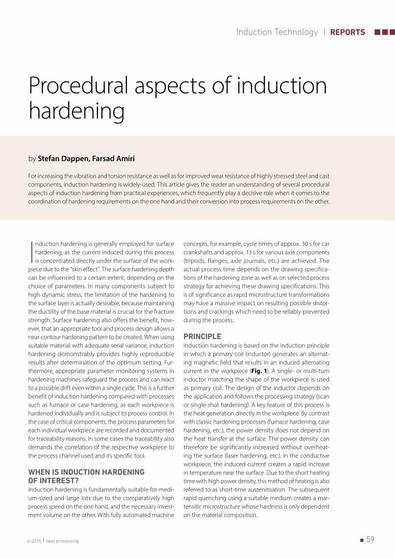
PRINCIPLEInduction hardening is based on the induction principle in which a primary coil (inductor) generates an alternat-ing magnetic field that results in an induced alternating current in the workpiece (Fig. 1). A single- or multi-turn inductor matching the shape of the workpiece is used as primary coil. The design of the inductor depends on the application and follows the processing strategy (scan or single-shot hardening). A key feature of this process is the heat generation directly in the workpiece. By contrast with classic hardening processes (furnace hardening, case hardening, etc.), the power density does not depend on the heat transfer at the surface. The power density can therefore be significantly increased without overheat-ing the surface (laser hardening, etc.). In the conductive workpiece, the induced current creates a rapid increase in temperature near the surface. Due to the short heating time with high power density, this method of heating is also referred to as short-time austenitisation. The subsequent rapid quenching using a suitable medium creates a mar-tensitic microstructure whose hardness is only dependent on the material composition.
60 heat processing 4-2015
REPORTS Induction Technology
Due to the dynamics of the process, complex part and hardening zone geometries make high demands on the process control, as only those areas of the workpiece are subjected to martensitic hardening that had previously been properly austenitised and then reached at least the critical cooling rate. In general the result of the heat treat-ment is dependent on the following factors:
■ Complexity of the part geometry, ■ Hardening demands (hardness, hardening depth, micro-
structure), ■ Alloy and initial microstructure of the material, ■ Process strategy (scan, standstill, rotation), ■ Process parameters (power, heating time, frequency,
quenching parameters), ■ Inductor design (e.g. coupling distance of the inductor).
With complex part and/or hardening zone geometries, however, there are mutual dependencies that preclude arbitrary combinations of surface hardening depth, lateral geometric form of the hardening zone and hardness profile. In view of the differences compared with conventional hardening processes, there are a number of specific ques-tions that are raised below:
■ What is the optimum heating for my material? ■ How do I evaluate the heating on the basis of metal-
lographic specimens (too hot, too cold)? ■ What is the optimum setting for induction heating? ■ What quenching does the material composition require? ■ What possibilities are there for tempering?
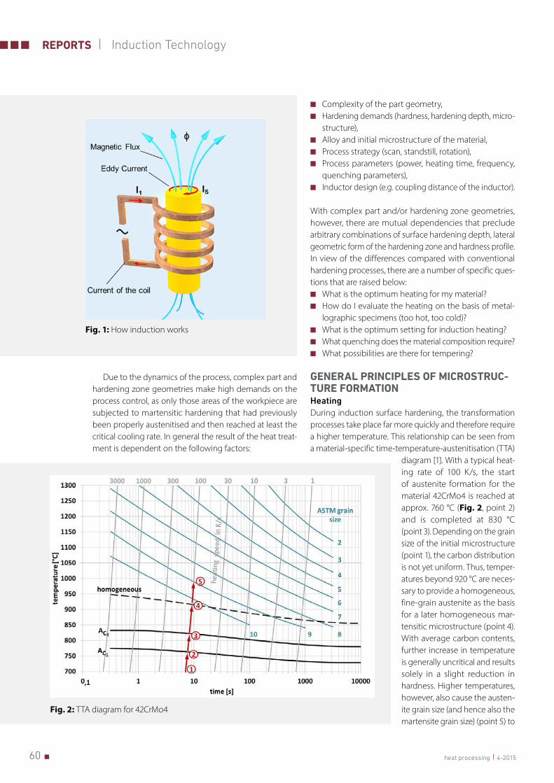
GENERAL PRINCIPLES OF MICROSTRUC-TURE FORMATION HeatingDuring induction surface hardening, the transformation processes take place far more quickly and therefore require a higher temperature. This relationship can be seen from a material-specific time-temperature-austenitisation (TTA)
diagram [1]. With a typical heat-ing rate of 100 K/s, the start of austenite formation for the material 42CrMo4 is reached at approx. 760 °C (Fig. 2, point 2) and is completed at 830 °C (point 3). Depending on the grain size of the initial microstructure (point 1), the carbon distribution is not yet uniform. Thus, temper-atures beyond 920 °C are neces-sary to provide a homogeneous, fine-grain austenite as the basis for a later homogeneous mar-tensitic microstructure (point 4). With average carbon contents, further increase in temperature is generally uncritical and results solely in a slight reduction in hardness. Higher temperatures, however, also cause the austen-ite grain size (and hence also the martensite grain size) (point 5) to
Fig. 1: How induction works
Fig. 2: TTA diagram for 42CrMo4
614-2015 heat processing
Induction Technology REPORTS
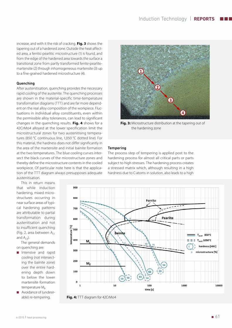
increase, and with it the risk of cracking. Fig. 3 shows the tapering out of a hardened zone. Outside the heat-affect-ed area, a ferritic-pearlitic microstructure (1) is found, and from the edge of the hardened area towards the surface a transitional zone from partly transformed ferrite-pearlite-martensite (2) through inhomogeneous martensite (3) up to a fine-grained hardened microstructure (4).
QuenchingAfter austenitisation, quenching provides the necessary rapid cooling of the austenite. The quenching processes are shown in the material-specific time-temperature transformation diagrams (TTT) and are far more depend-ent on the real alloy composition of the workpiece. Fluc-tuations in individual alloy constituents, even within the permissible alloy tolerances, can lead to significant changes in the quenching results. Fig. 4 shows for a 42CrMo4 alloyed at the lower specification limit the microstructural zones for two austenitising tempera-tures (850 °C continuous line, 1,050 °C dotted line). For this material, the hardness does not differ significantly in the area of the martensite and initial bainite formation at the two temperatures. The blue cooling curves inter-sect the black curves of the microstructure zones and thereby define the microstructure contents in the cooled workpiece. Of particular note here is that the applica-tion of the TTT diagram always presupposes adequate austenitisation.
This in return means that while induction hardening, mixed micro-structures occurring in near surface areas of typi-cal hardening patterns are attributable to partial transformation during austenitisation and not to insufficient quenching (Fig. 2, area between Ac1 and Ac3).
The general demands on quenching are:
■ Intensive and rapid cooling (not intersect-ing the bainite zone) over the entire hard-ening depth down to below the lower martensite formation temperature Mf,
■ Avoidance of (undesir-able) re-tempering.
TemperingThe process step of tempering is applied post to the hardening process for almost all critical parts or parts subject to high stresses. The hardening process creates a stressed matrix which, although resulting in a high hardness due to C-atoms in solution, also leads to a high
Fig. 3: Microstructure distribution at the tapering out of the hardening zone
Fig. 4: TTT diagram for 42CrMo4
62 heat processing 4-2015
REPORTS Induction Technology
brittleness of the material. If the material is now heated without the transformation temperature being reached, C-atoms go partially into solution and form carbides. This relieves the matrix and results in an increased ductility of the material that is normally accompanied by a reduction in hardness. Both the extent of the increase in ductility and the parallel reduction in hardness depend on the tempering parameters, temperature and time, between which there is a systematic dependence [2]. Different temperature/time combinations can therefore produce a similar tempering result. In the light of this, temper-ing from the residual heat and induction tempering are being more and more widely used, as these processes are also very fast and can substitute classic tempering furnaces accordingly for many demand profiles. By con-trast with furnace tempering, both tempering processes (induction, residual heat) allow different hardening zones with different hardness values to be created in one part. The characteristics of the individual processes are shown in Table 1.
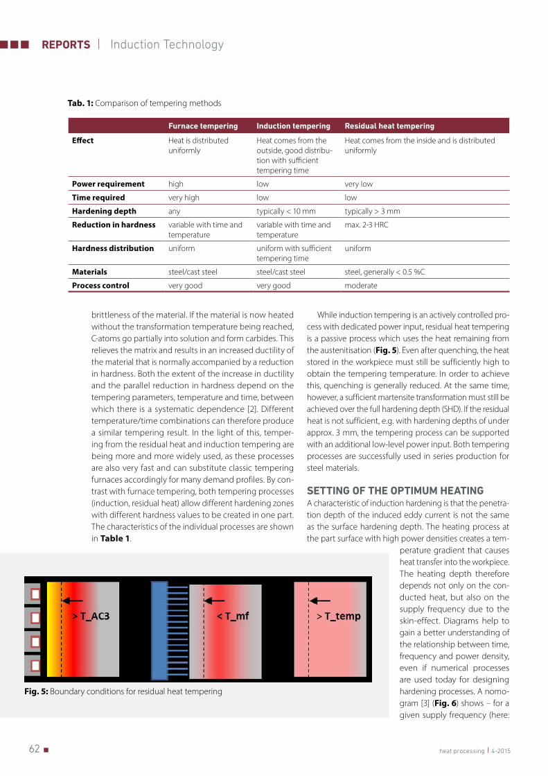
While induction tempering is an actively controlled pro-cess with dedicated power input, residual heat tempering is a passive process which uses the heat remaining from the austenitisation (Fig. 5). Even after quenching, the heat stored in the workpiece must still be sufficiently high to obtain the tempering temperature. In order to achieve this, quenching is generally reduced. At the same time, however, a sufficient martensite transformation must still be achieved over the full hardening depth (SHD). If the residual heat is not sufficient, e.g. with hardening depths of under approx. 3 mm, the tempering process can be supported with an additional low-level power input. Both tempering processes are successfully used in series production for steel materials.
SETTING OF THE OPTIMUM HEATINGA characteristic of induction hardening is that the penetra-tion depth of the induced eddy current is not the same as the surface hardening depth. The heating process at the part surface with high power densities creates a tem-
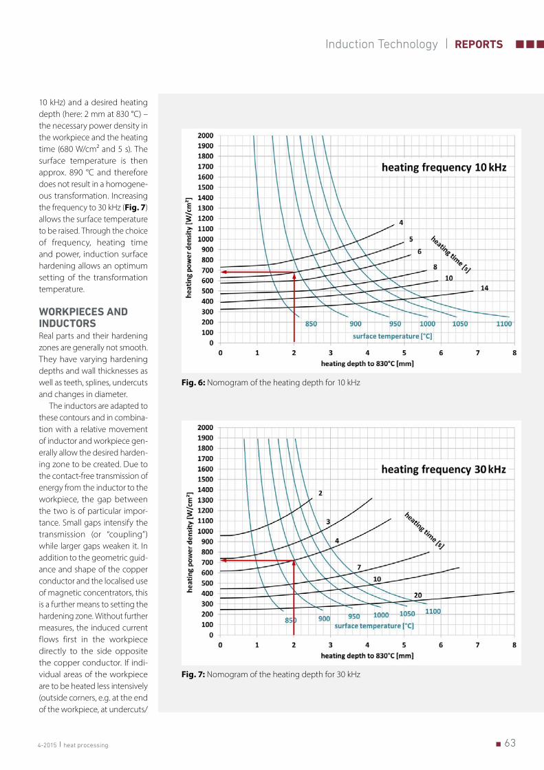
perature gradient that causes heat transfer into the workpiece. The heating depth therefore depends not only on the con-ducted heat, but also on the supply frequency due to the skin-effect. Diagrams help to gain a better understanding of the relationship between time, frequency and power density, even if numerical processes are used today for designing hardening processes. A nomo-gram [3] (Fig. 6) shows – for a given supply frequency (here:
Furnace tempering Induction tempering Residual heat tempering
Effect Heat is distributed uniformly
Heat comes from the outside, good distribu-tion with sufficient tempering time
Heat comes from the inside and is distributed uniformly
Power requirement high low very low
Time required very high low low
Hardening depth any typically < 10 mm typically > 3 mm
Reduction in hardness variable with time and temperature
variable with time and temperature
max. 2-3 HRC
Hardness distribution uniform uniform with sufficient tempering time
uniform
Materials steel/cast steel steel/cast steel steel, generally < 0.5 %C
Process control very good very good moderate
Tab. 1: Comparison of tempering methods
Fig. 5: Boundary conditions for residual heat tempering
634-2015 heat processing
Induction Technology REPORTS
10 kHz) and a desired heating depth (here: 2 mm at 830 °C) – the necessary power density in the workpiece and the heating time (680 W/cm² and 5 s). The surface temperature is then approx. 890 °C and therefore does not result in a homogene-ous transformation. Increasing the frequency to 30 kHz (Fig. 7) allows the surface temperature to be raised. Through the choice of frequency, heating time and power, induction surface hardening allows an optimum setting of the transformation temperature.
WORKPIECES AND INDUCTORSReal parts and their hardening zones are generally not smooth. They have varying hardening depths and wall thicknesses as well as teeth, splines, undercuts and changes in diameter.
The inductors are adapted to these contours and in combina-tion with a relative movement of inductor and workpiece gen-erally allow the desired harden-ing zone to be created. Due to the contact-free transmission of energy from the inductor to the workpiece, the gap between the two is of particular impor-tance. Small gaps intensify the transmission (or “coupling”) while larger gaps weaken it. In addition to the geometric guid-ance and shape of the copper conductor and the localised use of magnetic concentrators, this is a further means to setting the hardening zone. Without further measures, the induced current flows first in the workpiece directly to the side opposite the copper conductor. If indi-vidual areas of the workpiece are to be heated less intensively (outside corners, e.g. at the end of the workpiece, at undercuts/
Fig. 6: Nomogram of the heating depth for 10 kHz
Fig. 7: Nomogram of the heating depth for 30 kHz
64 heat processing 4-2015
REPORTS Induction Technology
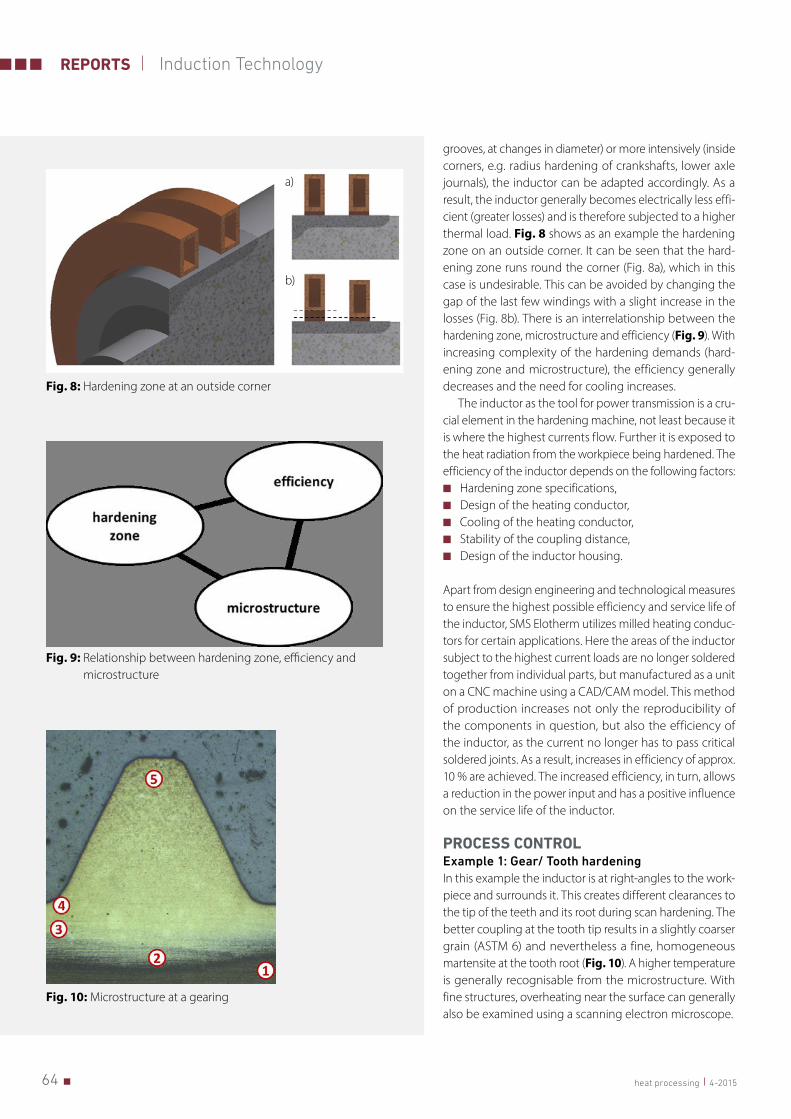
grooves, at changes in diameter) or more intensively (inside corners, e.g. radius hardening of crankshafts, lower axle journals), the inductor can be adapted accordingly. As a result, the inductor generally becomes electrically less effi-cient (greater losses) and is therefore subjected to a higher thermal load. Fig. 8 shows as an example the hardening zone on an outside corner. It can be seen that the hard-ening zone runs round the corner (Fig. 8a), which in this case is undesirable. This can be avoided by changing the gap of the last few windings with a slight increase in the losses (Fig. 8b). There is an interrelationship between the hardening zone, microstructure and efficiency (Fig. 9). With increasing complexity of the hardening demands (hard-ening zone and microstructure), the efficiency generally decreases and the need for cooling increases.
The inductor as the tool for power transmission is a cru-cial element in the hardening machine, not least because it is where the highest currents flow. Further it is exposed to the heat radiation from the workpiece being hardened. The efficiency of the inductor depends on the following factors:
■ Hardening zone specifications, ■ Design of the heating conductor, ■ Cooling of the heating conductor, ■ Stability of the coupling distance, ■ Design of the inductor housing.
Apart from design engineering and technological measures to ensure the highest possible efficiency and service life of the inductor, SMS Elotherm utilizes milled heating conduc-tors for certain applications. Here the areas of the inductor subject to the highest current loads are no longer soldered together from individual parts, but manufactured as a unit on a CNC machine using a CAD/CAM model. This method of production increases not only the reproducibility of the components in question, but also the efficiency of the inductor, as the current no longer has to pass critical soldered joints. As a result, increases in efficiency of approx. 10 % are achieved. The increased efficiency, in turn, allows a reduction in the power input and has a positive influence on the service life of the inductor.
PROCESS CONTROL Example 1: Gear/ Tooth hardeningIn this example the inductor is at right-angles to the work-piece and surrounds it. This creates different clearances to the tip of the teeth and its root during scan hardening. The better coupling at the tooth tip results in a slightly coarser grain (ASTM 6) and nevertheless a fine, homogeneous martensite at the tooth root (Fig. 10). A higher temperature is generally recognisable from the microstructure. With fine structures, overheating near the surface can generally also be examined using a scanning electron microscope.
Fig. 8: Hardening zone at an outside corner
a)
b)
Fig. 9: Relationship between hardening zone, efficiency and microstructure
Fig. 10: Microstructure at a gearing
654-2015 heat processing
Induction Technology REPORTS
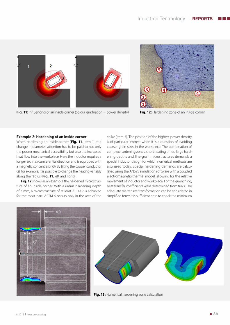
Example 2: Hardening of an inside cornerWhen hardening an inside corner (Fig. 11, item 1) at a change in diameter, attention has to be paid to not only the poorer mechanical accessibility but also the increased heat flow into the workpiece. Here the inductor requires a longer arc in circumferential direction and is equipped with a magnetic concentrator (3). By tilting the copper conductor (2), for example, it is possible to change the heating variably along the radius (Fig. 11, left and right).
Fig. 12 shows as an example the hardened microstruc-ture of an inside corner. With a radius hardening depth of 3 mm, a microstructure of at least ASTM 7 is achieved for the most part. ASTM 6 occurs only in the area of the
collar (item 5). The position of the highest power density is of particular interest when it is a question of avoiding coarser grain sizes in the workpiece. The combination of complex hardening zones, short heating times, large hard-ening depths and fine-grain microstructures demands a special inductor design for which numerical methods are also used today. Special hardening demands are calcu-lated using the ANSYS simulation software with a coupled electromagnetic-thermal model, allowing for the relative movement of inductor and workpiece. For the quenching, heat transfer coefficients were determined from trials. The adequate martensite transformation can be considered in simplified form: It is sufficient here to check the minimum
Fig. 11: Influencing of an inside corner (colour graduation = power density) Fig. 12: Hardening zone of an inside corner
Fig. 13: Numerical hardening zone calculation
66 heat processing 4-2015
REPORTS Induction Technology
temperatures achieved in the previously austenitised zone after quenching. After the quenching process, a thermal compensation generally occurs within the workpiece. Reheating can occur, hence leading to the – possibly undesirable – residual heat tempering of the hardening zone and must therefore also be checked. Fig. 13 shows
the recalculation (left, coloured area) of a bearing hardening by comparison with the measurement (left, grey area). The figures on the right show the temperature curve at the start of quenching (top) and the austenitised zone (bottom).
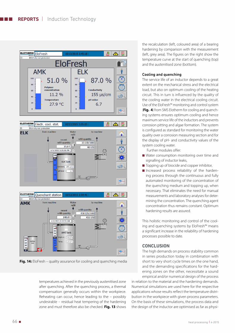
Cooling and quenchingThe service life of an inductor depends to a great extent on the mechanical stress and the electrical load, but also on optimum cooling of the heating circuit. This in turn is influenced by the quality of the cooling water in the electrical cooling circuit. Use of the EloFresh™ monitoring and control system (Fig. 4) from SMS Elotherm for cooling and quench-ing systems ensures optimum cooling and hence maximum service life of the inductors and prevents corrosion pitting and algae formation. The system is configured as standard for monitoring the water quality over a corrosion measuring section and for the display of pH- and conductivity values of the system cooling water.
Further modules offer: ■ Water consumption monitoring over time and signalling of inductor leaks,
■ Topping up of biocide and copper inhibitor, ■ Increased process reliability of the harden-ing process through the continuous and fully automated monitoring of the concentration of the quenching medium and topping up, when necessary. That eliminates the need for manual measurements and laboratory analyses for deter-mining the concentration. The quenching agent concentration thus remains constant. Optimum hardening results are assured.
This holistic monitoring and control of the cool-ing and quenching systems by EloFresh™ means a significant increase in the reliability of hardening processes possible to date.
CONCLUSIONThe high demands on process stability common in series production today in combination with short to very short cycle times on the one hand, and the demanding specifications for the hard-ening zones on the other, necessitate a sound empirical and/or numerical design of the process
in relation to the material and the hardening demands. Numerical simulations are used here for the respective applications whose results reflect the temperature distri-bution in the workpiece with given process parameters. On the basis of these simulations, the process data and the design of the inductor are optimised as far as physi-
Fig. 14: EloFresh – quality assurance for cooling and quenching media
674-2015 heat processing
Induction Technology REPORTS
cally possible. During the process evaluation, questions concerning the relationships between microstructure, formation of the hardening zone and the design of the inductor have to be considered. Furthermore, appro-priate measures – e.g. with regard to the actual power level required, inductor design, cooling and quenching circuits – must ensure that the highest possible avail-abilities can be achieved.
LITERATURE
[1] Orlich, J.; Rose, A.; West, P.: Atlas zur Wärmebehandlung der
Stähle, Band 3. Verlag Stahleisen, 1973
[2] Thomas, G. A.; et al.: LANL. Time-Temperature Equivalence in
Martensite Tempering, 2008
[3] Geisel, H.: Die Berechnung der Einwärmtiefe bei der Ober-
flächen-Induktionshärtung. Werkstattechnik und Maschinen-
bau, Heft 10, 1956
AUTHORS
Dr. Stefan DappenSMS Elotherm GmbHRemscheid, GermanyTel.: +49 (0) 2191 / [email protected]
Dipl. Ing. Farsad AmiriEvoprojekt / SMS Elotherm GmbHRemscheid, GermanyTel.: +49 (0) 160 / [email protected]
Handbook of Thermoprocessing Technologies, Vol.2This Handbook provides a detailed overview of the entire thermoproces-sing sector, structured on practical criteria, and is of particular assistance to manufacturers and users of thermoprocessing equipment. The book’s main intention is the presentation of practical thermal processing for the improve-ment of materials and parts in industrial application.
The second volume examines the different plants, their components and safety aspects.
Content: Melting – Heating – Heat treatment – Surface treatment – Cutting and joining – Fuel heating – Electrical heating – Plant safety – Explosion safety – Standards and legislation.
Editors: Franz Beneke, Bernard Nacke, Herbert Pfeifer 2nd edition 2015, approx. 1,028 pages, hardcover with interactive e-book (read-online access)ISBN: 978-3-8027-2976-8Price: € 240.-
PDF e-bookISBN: 987-3-8027- 3012-2Preis: € 200,-
Required Reading for Thermoprocess EngineersOrder now:Tel.: +49 201 82002-14
Fax: +49 201 82002-34
KNOWLEDGE FOR THE
FUTURE