Embed Size (px)
Citation preview

I:\SLF\54\INF-9.doc
E
SUB-COMMITTEE ON STABILITY AND LOAD LINES AND ON FISHING VESSELS SAFETY 54th session Agenda item 3
SLF 54/INF.910 November 2011
ENGLISH ONLY
DEVELOPMENT OF SECOND GENERATION INTACT STABILITY CRITERIA
A background study on application of MSC.1/Circ.1228 on the Revised Guidance to
the master for avoiding dangerous situations in adverse weather and sea conditions
Submitted by Germany
SUMMARY
Executive summary: With regard to the ongoing discussion on the need for guidance in the context of new generation intact stability criteria, this document provides background on the application of MSC.1/Circ.1228 that may be used when attempting to achieve validation and verification of the draft second generation intact stability criteria. This study is presented in order to support the current discussion in the Sub-Committee on the development of the criteria, as well as the need to making such criteria resilient and at the same time improving their acceptability.
Strategic direction: 5.2
High-level action: 5.2.1
Planned output: 5.2.1.16
Action to be taken: Paragraph 5
Related document: SLF 53/19, paragraph 3.7
Background 1 Reference is made to the ongoing discussion on new generation stability criteria within the SLF Sub-Committee. It was recognized in multiple cases that there was a need for a guidance and background studies supporting the development of such criteria. 2 The purpose of the attached study was to check the reliability of the Guidelines contained in circulars MSC/Circ.707 and MSC.1/Circ.1228 which had superseded the former. For several capsizing accidents, it was analysed whether the application of the guidelines would have avoided these accidents. The annex to this document contains an analysis of the possibility to avoid maritime accidents by the application of MSC.1/Circ.1228 and MSC/Circ.707, carried out by Patrick Schiller, TUHH (Technical University of Hamburg-Harburg), completed in September 2010.
SLF 54/INF.9 Page 2
I:\SLF\54\INF-9.doc
3 The Institute of Ship Design and Ship Safety, Hamburg University of Technology, studied eight capsizing accidents, two accidents where containers were lost, as well as two model test capsizings. All of these examples occurred in following seas. 4 The previous and current IMO guidelines were applied to these examples. It was found that in none of these cases, would the guidelines have delivered information which could have helped to prevent the accidents. Action requested of the Sub-Committee 5 The Sub-Committee is invited to consider the information provided and take action as appropriate.
***

SLF 54/INF.9 Annex
I:\SLF\54\INF-9.doc
ANNEX

SCHRIFTENREIHE SCHIFFBAU
Patrick Schiller
Analysis of the possibility to avoid maritime accidents by the application of MSC.1/Circ. 1228 and MSC/Circ. 707
November 2011

Diploma ThesisSeptember 2010
Analysis of the possibility to avoid maritimeaccidents by the application of MSC.1/Circ. 1228
and MSC/Circ. 707
Hamburg University of TechnologyInstitute of Ship Design and Ship Safety
Submitted by: cand. ing. Patrick SchillerMatriculation number: 29388
First Supervisor: Prof. Dr.-Ing. Stefan KrügerSecond Supervisor: Prof. Dr.-Ing. Moustafa Abdel-Maksoud
Tutor: Dipl.-Ing. Philip Augener
Translation into English by Prof. Dr.-Ing. Stefan Krüger,Dipl.-Ing. Hendrik Dankowski and Dipl.-Ing. Philip Augener
November 2011

Contents
List of figures IV
List of tables VII
Nomenclature VIII
Abstract 1
1 Introduction 2
2 Hazards to ships in heavy weather 32.1 Large angles of roll . . . . . . . . . . . . . . . . . . . . . . . . . . . . . . . . 32.2 Large accelerations . . . . . . . . . . . . . . . . . . . . . . . . . . . . . . . . 82.3 Surf-riding and broaching-to . . . . . . . . . . . . . . . . . . . . . . . . . . . . 8
3 Guidelines MSC.1/Circ. 1228 and MSC/Circ. 707 93.1 General . . . . . . . . . . . . . . . . . . . . . . . . . . . . . . . . . . . . . . . 93.2 The criteria . . . . . . . . . . . . . . . . . . . . . . . . . . . . . . . . . . . . 9
3.2.1 Surf-riding and broaching-to (K1) . . . . . . . . . . . . . . . . . . . . . 103.2.2 Successive high wave attack (K2) . . . . . . . . . . . . . . . . . . . . . 113.2.3 Synchronous rolling and parametric rolling motions (K3) . . . . . . . . 12
3.3 Collection of data for the application . . . . . . . . . . . . . . . . . . . . . . . 133.4 Method of application of the guidelines . . . . . . . . . . . . . . . . . . . . . 143.5 Further IMO documents relating on MSC/Circ. 707 . . . . . . . . . . . . . . . 16
3.5.1 SLF 44/INF.3 . . . . . . . . . . . . . . . . . . . . . . . . . . . . . . . 173.5.2 SLF 48/4/8 . . . . . . . . . . . . . . . . . . . . . . . . . . . . . . . . 18
4 Estimation of the natural roll frequency of ships 204.1 Small angles of roll . . . . . . . . . . . . . . . . . . . . . . . . . . . . . . . . 214.2 Larger angles of roll . . . . . . . . . . . . . . . . . . . . . . . . . . . . . . . . 224.3 In waves (simplified method) . . . . . . . . . . . . . . . . . . . . . . . . . . . 23
5 Assessing ship motions in waves by numerical simulations with E4-ROLLS 255.1 Natural sea states . . . . . . . . . . . . . . . . . . . . . . . . . . . . . . . . . 255.2 The simulation method . . . . . . . . . . . . . . . . . . . . . . . . . . . . . . 27
6 Analysis and examination 296.1 Analyzed ships . . . . . . . . . . . . . . . . . . . . . . . . . . . . . . . . . . . 296.2 Procedural method . . . . . . . . . . . . . . . . . . . . . . . . . . . . . . . . 306.3 Analysis . . . . . . . . . . . . . . . . . . . . . . . . . . . . . . . . . . . . . . 31
6.3.1 Real capsizing accidents . . . . . . . . . . . . . . . . . . . . . . . . . . 326.3.2 Model analyses . . . . . . . . . . . . . . . . . . . . . . . . . . . . . . 566.3.3 Other accidents . . . . . . . . . . . . . . . . . . . . . . . . . . . . . . 62
6.4 Summarization . . . . . . . . . . . . . . . . . . . . . . . . . . . . . . . . . . . 66
II

6.4.1 Criterion for surf-riding and broaching-to (K1) . . . . . . . . . . . . . 666.4.2 Criterion for successive high wave attack (K2) . . . . . . . . . . . . . . 676.4.3 Criterion for synchronous rolling and parametric rolling motions (K3) . . 67
7 Shortcomings of the guidelines 687.1 Successive high wave attack (K2) . . . . . . . . . . . . . . . . . . . . . . . . . 687.2 Synchronous rolling and parametric rolling motions (K3) . . . . . . . . . . . . . 687.3 Surf-riding and broaching-to (K1) . . . . . . . . . . . . . . . . . . . . . . . . . 697.4 Statements towards the validity of the guidelines . . . . . . . . . . . . . . . . . 69
8 Summary 70
References 71
Appendix 72
A FIDAMUS 74
B LOHENGRIN 75
C IRENE OLDENDORF 76
D HOHENEICHEN 77
E WILHELM 78
F HALSTENBEK 79
G FINNBIRCH 80
H COUGAR ACE 81
I JRS CANIS 82
J Container Vessel 83
III

List of Figures
1 Containers damaged by wave loads (left), green water on deck of a tanker(right), [1] and [2]. . . . . . . . . . . . . . . . . . . . . . . . . . . . . . . . . 3
2 M.V. Cougar Ace at 60° list (left), APL China with damaged cargo (right),[3] and [4]. . . . . . . . . . . . . . . . . . . . . . . . . . . . . . . . . . . . . 4
3 Principal sketch of direct excitation in beam seas, [5]. . . . . . . . . . . . . . . 54 Wave crest situation (green) and trough situation (blue), from [5]. . . . . . . . 65 Example of extreme alterations of the righting levers, where the stability com-
pletely vanishes on the crest. Accident situation of Halstenbek. . . . . . . . 66 Comparison of dangerous zones for K1 (707 left,1228 right). . . . . . . . . . . 117 Comparison of dangerous zones for K2 (707 left and 1228 right). . . . . . . . . 128 Sketch of application procedure for the guideline MSC/Circ. 707, from [6]. . . . 169 Example of a polar diagram with resonance lines (1:1 resonance full lines, 2:1
resonance broken lines) for a natural roll period of 15 s, from [7]. . . . . . . . . 1810 Example for a decreasing roll oscillation with a high initial roll angle [8] . . . . . 2011 Run of the still water lever arm curve above the initial tangent [9]. . . . . . . . 2112 Run of the still water lever arm curve close to the initial tangent [9]. . . . . . . 2113 Run of the still water lever arm curve far above the initial tangent [9]. . . . . . 2114 Estimation of GMeff , where A1 = A2 holds. . . . . . . . . . . . . . . . . . . 2315 Example for the estimation of a mean lever arm curve in waves . . . . . . . . . 2416 Long crested (left) and short crested waves (right) , from [10]. . . . . . . . . . 2517 Example of polar plots for long crested waves (left) and short crested waves
(right) for a roll angle of 50 °, from [11]. . . . . . . . . . . . . . . . . . . . . 2618 JONSWAP-Spectrum with constant energy abscissae, from [5]. . . . . . . . . . 2619 The equivalent wave, according to Grim, from [5]. . . . . . . . . . . . . . . . . 2820 General arrangement plan of SS Fidamus, from [11]. . . . . . . . . . . . . . . 3221 Polar diagrams for the accident situation (top) and for the secure loading con-
dition (bottom) of the Fidamus at a wave length of λ = 40 m (707 left-hand,1228 right-hand side of the polar diagrams). . . . . . . . . . . . . . . . . . . . 33
22 Curves of righting arms of the Fidamus for the accident situation (top) and forthe secure loading condition (bottom) within the reference wave with λ = 40 mand H = 2, 0 m. . . . . . . . . . . . . . . . . . . . . . . . . . . . . . . . . . 34
23 Profile view of MV Lohengrin, from [11]. . . . . . . . . . . . . . . . . . . . 3524 Polar diagrams for the accident situation (top) and the secure loading condition
(bottom) of the Lohengrin at a wave length of λ = 57 m (707 left-hand,1228 right-hand side of the polar diagrams). . . . . . . . . . . . . . . . . . . . 36
25 Curves of righting arms of the Lohengrin for the accident situation (top) andthe secure loading condition (bottom) within a reference wave with λ = 57 mand H = 2, 0 m. . . . . . . . . . . . . . . . . . . . . . . . . . . . . . . . . . 37
26 Profile view of SS Irene Oldendorf, from [11]. . . . . . . . . . . . . . . . 3827 Polar diagrams for the accident situation (top) and for the secure loading con-
dition (bottom) of Irene Oldendorf at a wave length of λ = 80 m (707left-hand, 1228 right-hand side of the polar diagrams). . . . . . . . . . . . . . 39
28 Curves of righting arms of Irene Oldendorf for the accident situation (top)and for the secure loading condition (bottom) within the reference wave withλ = 80 m and H = 5, 0 m. . . . . . . . . . . . . . . . . . . . . . . . . . . . 40
29 MV Hoheneichen completely loaded, from [11]. . . . . . . . . . . . . . . . . 41
IV

30 Polar diagrams for the accident situation (top) and the secure loading condition(bottom) of the Hoheneichen at a wave length of λ = 40 m (707 left-hand,1228 right-hand side of the polar diagrams). . . . . . . . . . . . . . . . . . . . 42
31 Curves of righting arms of Hoheneichen for the accident situation (top) andthe secure loading condition (bottom) within the reference wave with λ = 40 mand H = 4, 0 m. . . . . . . . . . . . . . . . . . . . . . . . . . . . . . . . . . 43
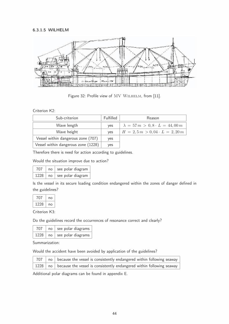
32 Profile view of MV Wilhelm, from [11]. . . . . . . . . . . . . . . . . . . . . 4433 Polar diagrams for the accident situation (top) and for the secure loading condi-
tion (bottom) of the Wilhelm at a wave length of λ = 57 m (707 left-hand,1228 right-hand side of the polar diagrams). . . . . . . . . . . . . . . . . . . . 45
34 Curves of righting arm of the Wilhelm for the accident situation (top) and thesecure loading condition (bottom) within the reference wave with λ = 57mand H = 2, 5 m. . . . . . . . . . . . . . . . . . . . . . . . . . . . . . . . . . 46
35 MV Halstenbek, from [11]. . . . . . . . . . . . . . . . . . . . . . . . . . . 4736 Polar diagrams for the accident situation (top) and the secure loading condition
(bottom) of the Halstenbek at a wave length of λ = 77 m (707 left-hand,1228 right-hand side of the polar diagrams). . . . . . . . . . . . . . . . . . . . 48
37 Curves of righting arms of the Halstenbek for the accident situation (top) andthe secure loading condition (bottom) within an reference wave with λ = 77 mand H = 4, 0 m. . . . . . . . . . . . . . . . . . . . . . . . . . . . . . . . . . 49
38 MV Finnbirch, [12]. . . . . . . . . . . . . . . . . . . . . . . . . . . . . . . 5039 Polar diagrams for the accident situation (top) and the secure loading condition
(bottom) of the Finnbirch at a wave length of λ = 113 m (707 left-hand,1228 right-hand side of the polar diagrams). . . . . . . . . . . . . . . . . . . . 51
40 Curves of righting arms of the Finnbirch for the accident situation (top) andthe secure loading condition (bottom) within a reference wave with λ = 113 mand H = 5, 0 m. . . . . . . . . . . . . . . . . . . . . . . . . . . . . . . . . . 52
41 General arrangement plan of the M.V. Cougar Ace, from [11]. . . . . . . . 5342 Polar diagrams for the accident situation (top) and the secure loading condition
(bottom) of the Cougar Ace at a wave length of λ = 172 m (707 left-hand,1228 right-hand side of the polar diagrams). . . . . . . . . . . . . . . . . . . . 54
43 Curves of righting arms of the Cougar Ace for the accident situation (top)and the secure loading condition (bottom) within the reference wave with λ =172 m and H = 3, 0 m. . . . . . . . . . . . . . . . . . . . . . . . . . . . . . . 55
44 Profile view of the DFDS-Flower-Class RoRo-Vessels, from [11]. . . . . . . . . . 5645 Polar diagram for the accident situation (top) and for the secure loading condi-
tion (bottom) of the Flower-Class vessels at a wave length of λ = 206 m(707 left-hand, 1228 right-hand side of the polar diagrams). . . . . . . . . . . . 57
46 Curves of righting arms of the Flower-Class vessels for the accident situation(top) and the secure loading condition (bottom) within the reference wave withλ = 206 m and H = 8, 8 m. . . . . . . . . . . . . . . . . . . . . . . . . . . . 58
47 Hull form of the SINBAD-Model, from [11]. . . . . . . . . . . . . . . . . . . . 5948 Polar diagrams for the accident situation (top) and for the secure loading con-
dition (bottom) of the SINBAD-Model at a wave length of λ = 160 m (707left-hand, 1228 right-hand side of the polar diagrams). . . . . . . . . . . . . . 60
49 Curves of righting arms of the SINBAD-Model for the accident situation (top)and the secure loading condition (bottom). . . . . . . . . . . . . . . . . . . . . 61
50 C.V. JRS Canis, [13]. . . . . . . . . . . . . . . . . . . . . . . . . . . . . . . 6251 Polar diagram for the accident situation of the JRS Canis at a wave length of
λ = 172 m (707 left-hand, 1228 right-hand side of the polar diagrams) for amaximum roll angle of ϕ = 20 °. . . . . . . . . . . . . . . . . . . . . . . . . . 63
V

52 Curves of righting arms of the JRS Canis for the accident situation within anreference wave with λ = 172 m and H = 7, 0 m. . . . . . . . . . . . . . . . . 63
53 Container Vessel, [14]. . . . . . . . . . . . . . . . . . . . . . . . . . . . . 6454 Polar diagram for the accident situation of the Container Vessel at a wave
length of λ = 172 m (707 left-hand, 1228 right-hand side of the polar diagrams)for a maximum roll angle of ϕ = 15 °. . . . . . . . . . . . . . . . . . . . . . . 65
55 Curves of righting arms of the Container Vessel for the accident situationwithin a reference wave with λ = 172 m and H = 7, 0 m. . . . . . . . . . . . 65
56 Illustration regarding the analysis of criterion K1 in summary (707 left-hand,1228 right-hand side of the polar diagram). . . . . . . . . . . . . . . . . . . . 66
57 Illustration regarding the analysis of criterion K2 in summary (707 left-hand,1228 right-hand side of the polar diagram). . . . . . . . . . . . . . . . . . . . 67
VI

List of Tables
1 Criteria and counter measures for K1. . . . . . . . . . . . . . . . . . . . . . . 102 Comparison of Criteria and counter measures for K2. . . . . . . . . . . . . . . 123 Comparison of criteria and counter measures for K3. . . . . . . . . . . . . . . . 134 Comparison of relevant data and their method of collection for the application
of the guidelines. . . . . . . . . . . . . . . . . . . . . . . . . . . . . . . . . . . 145 Data of the vessels, sailing and environmental conditions during the accidents. . 296 Stability data and analyzed wave lengths . . . . . . . . . . . . . . . . . . . . . 30
VII

Nomenclature
α Encounter angle (α = 0◦ head sea), [◦]
λ Wave length, [m]
μ Encounter angle (μ = 0◦ following sea), [◦]
� Displacement, [kg]
ϕ Roll angle respectively heeling angle, [◦]
B Breadth, [m]
c Wave speed, [m/s]
Cφ Rolling time coefficient, [−]
d Draught, [m]
Fn Froude-Number, [−]
GM Metacentric height, [m]
GZ Still water lever arm, [m]
H Wave height, [m]
H1/3 significant wave height, [m]
i Radius of gyration, [m]
Ixx Mass product of inertia, [kg · m2]
KG Vertical center of gravity, [m]
KM Distance from keel to metacenter, [m]
L Ship length (in the guidelines Lpp is meant), [m]
Lpp Length between perpendiculars, [m]
T ,TW Wave period, [s]
TE Encounter period, [s]
TR Natural period of roll, [s]
v, vS Ship speed, [kn]
B Center of buoyancy
VIII

BMBF Federal Ministry of Education and Research
FSG Flensburger Shipbuilders
G Center of gravity
HSVA Hamburg Ship Model Basin
IMO International Maritime Organization
LaSSe Joint research project: Loads on Ships in Seaways
M Metacenter
MSC Maritime Safety Committee
SLF Sub-Committee on Stability and Load Lines and on Fishing Vessels Safety
IX
Abstract
Scope of the present work is to check the reliability of the guidelines MSC/Circ. 707 resp.MSC.1/Circ. 1228. For several capsizing accidents it is analyzed whether the application ofthe guidelines would have avoided these accidents. Eight capsizing accidents, two accidentswhere containers were lost and two model test capsizings were studied, which all took place infollowing seas. The guidelines were applied to these cases. It was found that in none of theinvestigated cases, the guidelines would have delivered information which had helped to avoidthe accidents. This is due to present deficiencies of the guidelines, and it can be stated thatcomparable results would also be obtained, if the guidelines would be applied to other stabilityaccidents in following seas.
The main findings can be summarized as follows:
• The guidelines take into account criteria for the determination of potentially dangeroussituations which are not relevant for the real behaviour of ships in following seas.
• The simplifications of the physical effects made in the guidelines make the applicationon board quite easy. But these simplifications lead to incorrectly reflected physical phe-nomena, which leads to incorrect results and to the risk of not identifying dangeroussituations in the majority of applications.
• This leads to the fact that a dangerous zone indentified by the guidelines is not necessarilyan indication for a real danger. Depending on the individual stability of the ship, the realdangerous situation may be outside the zone as identified by the guideline or may evennot exist. In best case, counter measures are suggested which are unnecessary, becauseno real danger exists. But it is also well possible that counter measures suggested bythe guidelines will bring the ship into a real danger or into a situation which is moredangerous than before.
To put it softly: The application of the guidelines is comparable to gambling, as the obtainedresults are incorrect or misleading in the majority of applications.
1

1 Introduction
Due to the steady growth of the world economy the seaborne trade has significantly increasedover the last decades. This resulted in increased capacities of the ships, especially in thecontainer market. Besides increasing the number and capacities of the ships, the scheduleswere also tightened (just in time). The tight schedules demand for clearly specified departureand arrival times. The selection of a safe routing depending on the weather conditions mayhave become less important, compared to the pressure to keep the schedule. As a consequence,the probability that a ship may experience heavy weather conditions has increased. On theother hand, even careful weather routing can not avoid the fact the the ship may sometimesexperience rough weather conditions.
Ships are exposed to different dangers when operated in heavy weather, where the severestproblem are large roll angles. Unfortunately, at present no stability rules exist which take intoaccount the dynamic phenomena of a ship in a seaway except for the so called weather criterion.This criterion takes into account the combined action of beam wind and beam waves on theship. But it is well known that there are other situations than beam seas which are even moredangerous to the ship. But for these situations, which are strongly influenced by the dynamicbehaviour of each individual ship in a seaway, stability criteria do not exist.
On the other hand, the consequences of heavy weather damages are a significant problem forship owners and shipyards. The ship owners have problems when their cargo arrives late ordamaged. When the cargo is even lost, financial losses are the consequence. Further, the crewmay be exposed to risks which are not always acceptable. Therefore, the authorities do favourcriteria which help to reduce losses and which can assist the crew in the proper operating oftheir ship. For this purpose, the International Maritime Organization (IMO) in London hasdeveloped a guideline (MSC/Circ. 707) in 1995, which was later replaced by MSC.1/Circ.1227 dated 2007. These guidelines focus on the behaviour of ships in following seas, and theysuggest operational measures which are intended as a guideline for the crew to avoid dangeroussituations. However, it was doubted by several authors that these guidelines really give reliableanswers to the problem. One reason is that the guidelines are very general and do also not takeinto account the individual stability of the ship or the dynamic behaviour in waves.
Is is the scope of the present work to check the reliability of these guidelines. To do so, eightcapsizing accidents, two accidents with lost containers and two model test capsizings wereanalyzed. It is checked whether the guideline would have prevent the accidents if it would havebeen applied. After having analyzed each accident, it is then checked whether the guidelinewould have judged the accident situation as potentially dangerous, and which alternatives theguidelines would have proposed.
2

2 Hazards to ships in heavy weather
Ships which operate in heavy weather, that is rough seas and strong wind, are exposed toseveral hazards. It is possible that they meet situations which endanger the ship, the cargo,or even the crew. On the one hand these potential dangers result from wave loads, such asslamming or green water on deck. These wave loads can lead do damages to the cargo or tothe ship structure, see Fig. 1.
Figure 1: Containers damaged by wave loads (left), green water on deck of a tanker (right),[1] and [2].
On the other hand there are hazards due to the rolling of the ship, which is besides directwave loads also generated from the periodically changing stability in waves. The followingconsequences may occur:
• large amplitude rolling
• large transversal accelerations
• surf-riding and broaching-to
Depending on the actual stability of the ship either large roll angles or large transversal accel-erations or both may occur in a situation which is defined by the sea state, ship speed andencounter angle. But depending on the actual stability, the ship may also be safe in thatsituation.
In the following section the individual hazards due to ship motions are explained together withthe relevant physical phenomena. Hazards due to excessive wave loads are disregarded in thiscontext, as this problem is not affected by the stability of the ship.
2.1 Large angles of roll
Large roll angles are quantitatively hard to define as it depends on the individual ship when a rollangle may be called large. Because depending on the ship type and size different magnitudesof roll angles may be called large. Therefore, a large roll angle is defined as a roll angle whichleads to one of the following events:
• capsizing
3

• submerging of important non weathertight openings
• cargo shift or loss of cargo
• failure of important ship systems
• any situation which leads to an even larger roll angle.
The occurrence of large roll angles is therefore an event which causes high financial losses upto the total loss of the ship (Fig. 2). The reasons for the occurrence of large roll angles maybe the following:
• direct wave moments
• pure loss of stability on the wave crest
• parametric excitation
In a natural seaway (short crested and irregular), all effects do always appear in any possiblecombination. It is not possible to separate them. It is also possible that the combination ofthese effects leads to an amplification of the roll motion. These effects are described in thefollowing.
Figure 2: M.V. Cougar Ace at 60° list (left), APL China with damaged cargo (right), [3]and [4].
Direct Excitation
Direct excitation of the roll motion is explained here for a ship in beam seas. Fig. 3 showsa simple cross section of a ship which is exposed to a beam wave. It can be seen that the(momentary) centre of buoyancy is laterally shifted, like for example if the ship heels. Thisresults in the (momentary) righting lever h between weight and buoyancy, and a moment isgenerated which initiates a roll motion. This is called a direct excitation, as the situation resultsin a (time dependent) heeling or righting moment.
4

Figure 3: Principal sketch of direct excitation in beam seas, [5].
The danger that direct excitation in beam seas leads to large roll angles or even to the capsizingof the vessel is quite small, at least for typical merchant vessel having roughly sufficient stability.Because to excite large roll angles in beam seas, a resonance situation must be present whichis possible only for waves having quite a large wave length. These waves have a small wavesteepness ratio and result therefore in small direct moments only. Further, a portion of theenergy introduced into the ship is dissipated by the drifting motion, which leads to additionalroll damping. But in any natural sea state, the direct excitation is always present and may insome cases be the dominating effect, especially when combined with the other effects and whenthe ship travels in following or head seas.
This was most illustrated during the accident of the Chicago Express [15], where the shipsuffered from extremely large roll angles in head seas due to direct excitation without meetingany resonance situation.
Pure loss of stability
Pure loss of stability (on the wave crest) depends of the hull form and the stability (in waves).Because in longitudinal waves the stability varies between the crest and the trough situation,which may be regarded as the two characteristical situations for the problem. If the ship is onthe wave crest, the crest is amidships, and vice versa for the trough situation (see Fig. 4).
As the buoyant distribution varies between these two situations, the ship has reduced stabilityon the wave crest and increased stability if the trough is amidships (both compared to theequivalent stillwater situation). This effect can be seen at the different righting lever curvesin Fig. 5. The stability alterations increase when the wave height increases, and if the wavelength equals 0.7 to 1.3 times ship length, the stability alterations become most pronounced.Where the shorter waves lead to more pronounced stability alterations and are most dangerous.
5

Figure 4: Wave crest situation (green) and trough situation (blue), from [5].
Figure 5: Example of extreme alterations of the righting levers, where the stability completelyvanishes on the crest. Accident situation of Halstenbek.
If the stability loss on the wave crest becomes that large that the stability completely vanishes,this is called pure loss of stability on the wave crest. If the ship remains in that crest situation,it will capsize as there is no righting moment at all. The ship may also not capsize on thatcrest if the crest situation disappears fast enough. But large roll angles or a capsize may occurin a pure loss of stability condition.
Pure loss of stability may occur either in head or in following seas. The latter situation is moredangerous, because the ship remains in that situation for a much longer time compared to headseas. This situation does often appear together with other effects which have already initiateda roll motion. If the ship heels significantly in such a situation, it has the tendency to broachwhich makes it sometimes difficult to decide whether the primary failure mode was pure loss ofstability or broaching-to.
6

Parametric Excitation
Parametric excitation is defined when a motion is not excited by a direct force or moment, butindirectly via a parameter. In case of parametric rolling of ships this parameter is the variationof the righting lever in waves. The righting lever of a ship varies in waves (see above, 5).These alterations of the righting lever solely depend on the hull form of the ship, not on thestability. Especially the modern hull forms of container vessels and RoRo- ships with their flaredforebodies and barge type aftbodies are characterized by substantial alterations of the rightinglevers in waves.
Most dangerous is the parametric excitation in either following or head seas when resonancesare met. Here, the so called 1:1 resonance (encounter period equals natural roll period) or the2:1 resonance (encounter period equals 2 times the natural roll period) are most important.
The 2:1 resonance is met when two pitch cycles coincide with one roll cycle. This situationis by far the most dangerous situation, because the wave crest is always amidships when theship is in an upright position. In this situation, the ship may heel to one side. If the troughis amidships, the ship has its maximum heeling angle and is then uprighted by the increasedstability of the trough condition. In irregular, short crested seaways where there is always adirect excitation present, only a few roll cycles are required to build up large roll amplitudes.To experience a 2:1 parametric roll resonance, several criteria need to be met which stronglydepends on the stability of the ship:
If the ship travels in following seas, 2:1 resonances can only be met at relatively low values ofstability in low ship speeds. Due to the low stability, the transversal accelerations may not bethat large, but large roll angles may occur, which can lead to capsizing. It is very important forthe general understanding of the ship’s behaviour that also its natural roll period may stronglyvary if the ship travels in following seas. Because the natural roll period depends on the stabilityof the ship, and the latter permanently varies. The variation of the natural roll period becomeslarger if the stability alterations become larger. The ship adapts itself to the excitation, andthis results in the fact that there is no distinct sharp roll resonance, but a broadband region ofsituations which do all lead to a 2:1 parametric excitation. If this is superimposed by pure lossof stability, many situations in following seas can occur where capsizing or large roll angles arepossible.
If the ship travels in head seas, the 2:1 situation is met at relatively large values of stability atsmall ship speeds. Due to the large stability and the short times on the wave crest, large rollangles are hardly possible, but large accelerations can be found quite often. Because the rollperiod of the ship does not vary as much as in following seas, the resonant situation is morepronounced and it is more difficult to actually meet a 2:1 resonance situation in head seas.
The 1:1 resonance, where the encounter period meets the natural roll period (in waves) is (fortypical vessels and stability values) only possible in following seas at relatively high speeds. Asthe roll damping is normally high at that speeds, is is only at very low values of stability possiblethat critical roll angles occur. Exemptions are the accidents of the Finnbirch [11] and of theFidamus [11].
7
2.2 Large accelerations
Large accelerations - in this context transversal accelerations - are defined as accelerationswhich lead to the following events:
• massive cargo loss or cargo damages
• heavy damages at machinery systems or vital safety systems
• structural overload of safety relevant structural members
• injuries to the crew
It becomes obvious that large accelerations lead to heavy damages to the ship and potentiallyto the crew, but not necessarily to the total loss of the ship. An example for such an eventmay be the accident of the Chicago Express , where the ship rolled heavily in a typhoon,and as a consequence several crew members were thrown through the bridge [15]. One crewmember was killed and several were injured, the ship itself remained undamaged.
It must be pointed out that large accelerations do not necessarily coincide with large roll anglesand vice versa. Even at relatively small roll angles, large accelerations can occur if the stabilityis large enough or if a 2:1 resonance in head seas is met (see above).
2.3 Surf-riding and broaching-to
Surf-riding and broaching-to occurs in following seas if the ship travels on a steep wave crest.Typically the speed of a wave equaling ship length is larger than the ship speed, and the waveovertakes the ship. In such a situation it is possible that the overtaking wave accelerates theship in such a way that it starts to ride on that wave (surf-riding). If this situation is combinedwith insufficient stability on the wave crest, the ship may capsize or experience large roll angles(see 5). Surf-riding also increases the time interval when the ship remains in the crest position.
On the other hand the danger exists that the ship broaches after surf-riding. The main root ofthat failure mode is a yawing moment introduced into the ship (by the waves) or insufficientcourse keeping ability, e.g. when the forebody of the ship dives into the next wave crest.Due to the wave induced velocities, the relative flow speed to the ship’s rudder is significantlydecreased, which decreases the manoeuvrability of the ship further. The large yawing motionconnected to broaching-to causes large centrifugal forces, which can lead to the capsizing ofthe ship.
Broaching-to problems are not really problems connected to intact stability failures, becausebroaching-to can not be avoided by moderate alterations of the stability a such. It is morea manoeuvring problem in waves. The application of the guidelines to the selected accidents(where no accident happened due to broaching-to) further showed that surf-riding an broaching-to problem play a minor role only for typical merchant ships at reasonable speeds. Therefore,the main focus of this work is stability related problems.
8
3 Guidelines MSC.1/Circ. 1228 and MSC/Circ. 707
In the following, the two guidelines MSC.1/Circ. 1228 [16] and MSC/Circ. 707 [6] are discussedand compared to each other. The focus is on the different criteria of these guidelines which areintended to identify critical situations in following seas and on the proposed counter measures.Also, the collection of the relevant data is discussed. Additionally, further IMO- documentswhich reference these guidelines are analyzed. The two guidelines will in the following beabbreviated by 707 or 1228, respectively.
3.1 General
The guideline MSC.1/Circ. 1228, which was published by the IMO January 11th, 2007, replacesthe guideline MSC/Circ. 707, published October 19th, 1995. As the titles of the guidelines
„REVISED GUIDANCE TO THE MASTER FOR AVOIDING DANGEROUS SITUATIONS INADVERSE WEATHER AND SEA CONDITIONS“ (1228)
resp.
„GUIDANCE TO THE MASTER FOR AVOIDING DANGEROUS SITUATIONS IN FOLLOW-ING AND QUARTERING SEAS“ (707)
show, both guidelines include recommendations for the master to avoid dangerous situationsin heavy weather, especially in following and stern quartering seas. The focus is on excessivemotions, which may lead to large roll angles or to the capsizing of the vessel (707 and 1228),damages to the cargo, major systems and the crew (mentioned in 1228 only). The treatedfailure modes are surf-riding and broaching-to, pure loss of stability on the wave crest andsynchronous and parametric rolling. Other hazards - such as structural damages - are notincluded in the guidelines, which is explicitly mentioned in 1228.
Due to the new title of the 1228 and the fact the the guideline is a revision of the 707, one couldassume that 1228 goes more into detail with respect to the different hazards. This is clearly notthe case. Some aspects are mentioned more detailed, e.g the alteration of the natural rollingperiod of the ship in following seas, (ref. 2.1), but the guideline is kept very general and doesnot treat the different hazards in detail. The focus is - as in 707 - on hazards in following andstern quartering seas.
3.2 The criteria
The guidelines 707 and 1228 include three different criteria, which are intended to avoid thefollowing hazards in heavy weather:
• Surf-riding and broaching-to (K1)
• Successive high wave attack (K2)
9

• Synchronous rolling and parametric rolling motions (K3).
All these three criteria - in the following denoted by K1, K2 and K3 define a so called dangerouszone, depending on several input parameters. During navigation, this dangerous zone shall beavoided by the master, or, if he finds himself to navigate in a dangerous zone, he is recommendedto leave that zone, if additional criteria are met. The application of the criteria requires thatthe stability of the ship fulfills at least the IS- code (or comparable). Further the guidelinesspecify that following or stern quartering seas denote encounter angles between μ = 0° − 45°This is not explicitly mentioned in 1228. In the following, the criteria are introduced.
3.2.1 Surf-riding and broaching-to (K1)
The first criterion K1 deals with the hazards of surf-riding and broaching-to. According tothe criterion, surf-riding or broaching-to may occur if the ship exceeds a certain critical speedin relation to its length. (see table 1). This results in the dangerous zones as shown in Fig.6, which includes encounter angles of μ = 45° to both sides. The guideline 707 additionallyidentifies a dangerous zone where the ship is significantly accelerated by the waves. Thisadditional zone is no more included in the 1228, which may indicate that this hazard was foundto be not relevant. To leave this dangerous zone, the guidelines recommend alterations ofcourse and/or speed.
MSC/Circ. 707 MSC.1/Circ. 1228Criterion
vs > 1.8√
L
dangerous zone from
vs > 1.4√
L
Dangerous zone see Fig. 6 left
vs >1.8
√L
cos(180 − α)
if 135° < α < 225°
Dangerous zone see Fig. 6 right
Action Speed reduction Speed and/or course alteration
Table 1: Criteria and counter measures for K1.
10

Figure 6: Comparison of dangerous zones for K1 (707 left,1228 right).
Fig. 6 further shows that the boundaries of the dangerous zones depend on the ratio v [kn]√L [m]
.Therefore, these boundaries are more or less constants and do not depend on other parameters,e.g the seastate. This ratio is more or less the ship’s Froude number, which is defined as:
Fn =v√g · L (1)
Using the Froude number as boundary definition of the dangerous zones, one obtains a Froudenumber of Fn = 0, 296 for the main dangerous zone resp. Fn = 0, 230 for the transition zonefor an encounter angle of μ = 0°. For other encounter angles, the Froude numbers increaseaccordingly. This indicates that the guidelines identify only relatively fast vessels as potentiallyendangered.
3.2.2 Successive high wave attack (K2)
The second criteria K2 of the guideline is intended to avoid the hazard of encountering a groupof higher waves, which may lead to pure loss of stability, to synchronous rolling, to parametricrolling or to a combination. The master shall take appropriate action if the waves exceed acritical length with respect to ship length and a certain (significant) wave height (see table 2)and when he additionally notes a dangerous behaviour of the vessel, which is not specified. Ifthese conditions are met, the master is recommended not to navigate in the dangerous zoneshown in Fig. 7. If he finds himself navigating in that dangerous zone, he is recommended toleave it by a course and/or speed alteration.
11

MSC/Circ. 707 MSC.1/Circ 1228Criterion
λ > 0.8 · L and H1/3 > 0.04 · L
and dangerous behaviour of the ship isnoted
Dangerous zone see Fig. 7 left (equalsTE ≈ 1.5 − 2.8 · T )
λ > 0.8 · L and H1/3 > 0.04 · Land dangerous behaviour of the ship isnoted
Dangerous zone see Fig. 7 right (equalsTE ≈ 1.8 − 3.0 · TW )
Action Speed and/or course alteration Speed and/or course alteration
Table 2: Comparison of Criteria and counter measures for K2.
Figure 7: Comparison of dangerous zones for K2 (707 left and 1228 right).
Both dangerous zones extend to an encounter angle of μ = 45°. The upper and the lowerboundary are defined by a constant ratio of ship speed and the wave period. Therefore, theboundaries depend on the actual sea state. A comparison of the dangerous zones accordingto both guidelines shows that the dangerous zone of 1228 is smaller. This mainly affects theregion with smaller ratios of v
TW. This means that 1228 considers lower ship speeds (at given
wave period) or larger wave periods (at given ship speed) not as dangerous anymore, comparedto the 707.
3.2.3 Synchronous rolling and parametric rolling motions (K3)
The last criterion K3 deals with the explicit danger of synchronous and parametric rolling. Themaster shall avoid situations where the encounter period equals one time or two times thenatural roll period of the vessel. As counter measures the guidelines propose to reduce the shipspeed or to alter course and speed in such a way that resonant situations for the given period of
12

the sea state can be avoided. How far away from a resonant situation the master shall navigateis not specified. Besides minor details concerning the counter measures both guidelines aremore or less the same, as table 3 shows.
MSC/Circ. 707 MSC.1/Circ 1228Criteria to be avoided:
TE ≈ TR
orTE ≈ TR/2
to be avoided:
TE ≈ TR
orTE ≈ TR/2
Action Speed reduction Speed and/or course alteration
Table 3: Comparison of criteria and counter measures for K3.
3.3 Collection of data for the application
To apply both guidelines, some data must be collected on board concerning the ship and theseastate. The data and the way how these data shall be collected are listed in table 4 for bothguidelines:
13

Wert MSC/Circ. 707 MSC.1/Circ 1228v Estimation of speed by an appropriate
method.not mentioned
μ, α From observations. The wind directionmay be taken as the direction of theseaway. The latter can eventually betaken from the radar.
not mentioned
T, TW Measurement of period by observationof the foam of the crests using a clock.N cycles shall be observed, the obtainedtime to be divided by N.
see MSC/Circ. 707
λ Estimation of λ either by observationand comparison to ship length or frommeasurements of the radar plot. T canbe computed by the formula:
T = 0.8√
λ
Estimation of λ either by observationand comparison to ship length or frommeasurements of the radar plot. Waveperiod TW and wave length λ depend oneach other as follows:
λ = 1.56 · T 2W or TW = 0.8
√λ
TE Measurement of the pitching motionusing a clock.
Measurement of the pitching motion orcomputation by the following formula:
TE =3T 2
W
3TW + v · cos(α)
TR Measurement of roll motion in calmwater or using the formula:
TR = 2 · C · B/√
GM
whereC = 0.373 + 0.023(B/d)− 0.43(L/100),oder equivalent estimation of C.
Estimation from the roll motion in calmwater.
H 13
not mentioned To be estimated from observations
Table 4: Comparison of relevant data and their method of collection for the application of theguidelines.
The collection of the data can be performed with simple means and methods which are applica-ble on board. The advantage (in theory) is that the guidelines can easily be applied on board ofevery ship. In practice, this is often hardly possible. For example, the wave height or the waveperiod are extremely difficult to estimate if one can not observe the waves, e.g. during night.Additionally, the accuracy is questionable, e.g. for the significant wave height. Additionally, the1228 does not mention the determination of the speed and the encounter angle. It is furtherquite vague concerning estimation or determination.
3.4 Method of application of the guidelines
For the application of the guideline 707, the procedure as shown in Fig. 8 is provided. Here,the three criteria K1 - K3 are checked sequentially, and it is determined whether the ship findsitself in one of the dangerous zones. If that is the case, the relevant counter measures are to
14

be performed to leave the dangerous zone. Then, the next criterion is checked for the newsituation. If the ship was not in a dangerous zone before, then the next criterion is applied to theinitial situation. This method is kept until the last criterion (K3) was applied. In the guideline707 it is pointed out (omitted in guideline 1228) that in case a speed reduction is required,the speed shall not fall below the minimum speed which is required for safe manoeuvering infollowing seas.
The guideline 1228 does not recommend any procedure of its application. One reason may bethat the guideline 1228 is not intended for following sea hazards only, which the criteria K1and K2 focus on. Therfore, the criterion K3 is valid for all encounter angles, and then, theprocedure suggested for the 707 then does not fit to the guideline 1228. If one would onlyfocus on following seas during the application of the guideline 1228, the same procedure as forthe 707 can be applied.
15

Figure 8: Sketch of application procedure for the guideline MSC/Circ. 707, from [6].
3.5 Further IMO documents relating on MSC/Circ. 707
During the publication of the guideline MSC/Circ. 707 and its replacement by MSC.1/Circ.1228, two further documents were published by IMO which make reference to the guideline
16
707. These documents are SLF 44/INF.3 [7] and SLF 48/4/8 [17]. Both documents weresubmitted by Germany, and they were submitted due to the fact that further knowledge hadbeen collected concerning the related physical phenomena. It is further indicated how a newguideline 1228 could have been developed.
3.5.1 SLF 44/INF.3
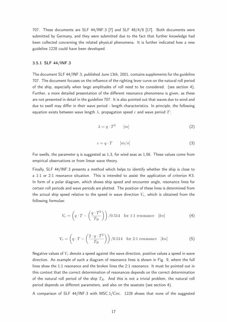
The document SLF 44/INF.3, published June 13th, 2001, contains supplements for the guideline707. The document focuses on the influence of the righting lever curve on the natural roll periodof the ship, especially when large amplitudes of roll need to be considered. (see section 4),Further, a more detailed presentation of the different resonance phenomena is given, as theseare not presented in detail in the guideline 707. It is also pointed out that waves due to wind anddue to swell may differ in their wave period - length characteristics. In principle, the followingequation exists between wave length λ, propagation speed c and wave period T :
λ = q · T 2 [m] (2)
c = q · T [m/s] (3)
For swells, the parameter q is suggested as 1,3, for wind seas as 1,56. These values come fromempirical observations or from linear wave theory.
Finally, SLF 44/INF.3 presents a method which helps to identify whether the ship is close toa 1:1 or 2:1 resonance situation. This is intended to assist the application of criterion K3.In form of a polar diagram, which shows ship speed and encounter angle, resonance lines forcertain roll periods and wave periods are plotted. The position of these lines is determined fromthe actual ship speed relative to the speed in wave direction Vr, which is obtained from thefollowing formulae:
Vr =(
q · T −(
q · T 2
TR
))/0.514 for 1:1 resonance [kn] (4)
Vr =(
q · T −(
2 · q · T 2
TR
))/0.514 for 2:1 resonance [kn] (5)
Negative values of Vr denote a speed against the wave direction, positive values a speed in wavedirection. An example of such a diagram of resonance lines is shown in Fig. 9, where the fulllines show the 1:1 resonance and the broken lines the 2:1 resonance. It must be pointed out inthis context that the correct determination of resonances depends on the correct determinationof the natural roll period of the ship TR. And this is not a trivial problem, the natural rollperiod depends on different parameters, and also on the seastate (see section 4).
A comparison of SLF 44/INF.3 with MSC.1/Circ. 1228 shows that none of the suggested
17

Figure 9: Example of a polar diagram with resonance lines (1:1 resonance full lines, 2:1 reso-nance broken lines) for a natural roll period of 15 s, from [7].
improvements was adopted in the guideline 1228.
3.5.2 SLF 48/4/8
SLF 48/4/8 contains a proposal for a revised Version of the guideline MSC/Circ.707 and waspublished June 19th, 2005. The main difference with respect to the guideline 707 lies in themore detailed description of the different phenomena which are responsible for the differenthazards in heavy weather. As in SLF 44/INF.3, the focus is on the influence of the rightinglever curve on the natural roll period and on the different resonances in head, following or beamseas. Further details my derived from the source itself or from the sections 4 and 2.1 of thisthesis. But the criteria published in the guideline have remained unchanged and were directlytransmitted from the guideline 707. The proposals of SLF 44/INF.3 for the criterion K3 havenot been adopted in the guideline.
If the proposal suggested by SLF 48/4/8 is compared to the guideline MSC.1/Circ. 1228, itcan be stated that the guideline is only a short and not very detailed summary of this proposal,where only a few sentences have been adopted. Therefore, only a small portion of the availableknowledge is represented by the guideline.
From our point of view, this was a step towards the wrong direction: Because only a personwhich is well familiar with the principal phenomena is able to judge upon the individual hazard
18

and is therefore able to operate the ship in heavy weather. And this is the main target of theguideline 1228.
19
4 Estimation of the natural roll frequency of ships
The natural roll period of a ship is the duration it takes for an inclined ship, without any externalmoments, to perform a whole rolling cycle. This time depends on the following aspects:
• the stability of the ship,
• the mass moment of inertia,
• the inclining angle.
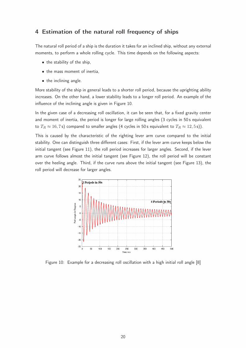
More stability of the ship in general leads to a shorter roll period, because the uprighting abilityincreases. On the other hand, a lower stability leads to a longer roll period. An example of theinfluence of the inclining angle is given in Figure 10.
In the given case of a decreasing roll oscillation, it can be seen that, for a fixed gravity centerand moment of inertia, the period is longer for large rolling angles (3 cycles in 50 s equivalentto TR ≈ 16, 7 s) compared to smaller angles (4 cycles in 50 s equivalent to TR ≈ 12, 5 s)).
This is caused by the characteristic of the righting lever arm curve compared to the initialstability. One can distinguish three different cases: First, if the lever arm curve keeps below theinitial tangent (see Figure 11), the roll period increases for larger angles. Second, if the leverarm curve follows almost the initial tangent (see Figure 12), the roll period will be constantover the heeling angle. Third, if the curve runs above the initial tangent (see Figure 13), theroll period will decrease for larger angles.
Figure 10: Example for a decreasing roll oscillation with a high initial roll angle [8]
20

Figure 11: Run of the still water lever arm curve above the initial tangent [9].
Figure 12: Run of the still water lever arm curve close to the initial tangent [9].
Figure 13: Run of the still water lever arm curve far above the initial tangent [9].
4.1 Small angles of roll
The natural roll frequency of a ship in still water conditions for small angles (below 5-10°) canbe estimated in different ways.
21

One approach is the roll decay test. The ship is inclined to one side and left lose. It oscillatesaround the equilibrium floating position with it’s natural frequency. The duration of this periodcan simply be measured,
Another approach is to idealize the ship as a one degree of freedom frequency system. Theeigenperiod can simply be determined by it’s uprighting moment (stiffness) and mass momentof inertia. This gives the well-known formula by Weiss
TR =2 · π · i√g · GM
[s], i =
√Ixx
� ≈ 0, 4B (6)
The GM-value is the characteristic stiffness and i the gyration radius, which is simply thefraction of the mass moment of inertia Ixx and the displacement Δ of the ship. For most usualships, the radius of gyration can be estimated by 0,4-times the ships breadth.
For ships with large deck cargo or any other high superstructures, this value may increase upto 0, 45 B. This formula is only valid for larger heeling angles, if the still water lever arm curveis close to linear for a large range (compare Figure 12).
4.2 Larger angles of roll
The natural roll period for large angles can also be estimated by several methods. The rolldecay test is only theoretically possible, since the required forces would be too large for realships. A simulation in the time-domain would be possible. Another approach is to use formulas,which take into account further characteristics of the lever arm curve. These are for examplegiven in [9] and reads for 30° respectively 40° as follows:
T30° =Cφ · B9, 4
(2, 2√
w+
2, 5√x
+4√y
+1, 5√
z
)[s] (7)
T40° =Cφ · B9, 4
(2, 2√
v+
2√w
+4√x
+4√y
+1√z
)[s] (8)
The Cφ value is a factor for the roll period and v, w, x, y and z variables based on valuesof the still water lever arm curve at different angles. For further details see [9]. It should bementioned that it is not clear how accurate these formulas are, since no validation has beenperformed so far. In addition, these formulas are based on the still water lever arm curve. whichmeans that these can only be applied to the following two situations:
• Close to beam sea conditions, since for any practical situation the effective stability canbe well estimated by the still water lever arm curve.
• In head sea conditions, if the mean lever arm curve of wave crest and trough gives almostthe still water curve. The stability oscillations are moderate in that case and the averageeffective stability is close to the stability in still water.
This is also true for another approach, where the roll period at large angles is estimated by aso-called effective GM-value. This approach takes into account that the area of the lever arm
22
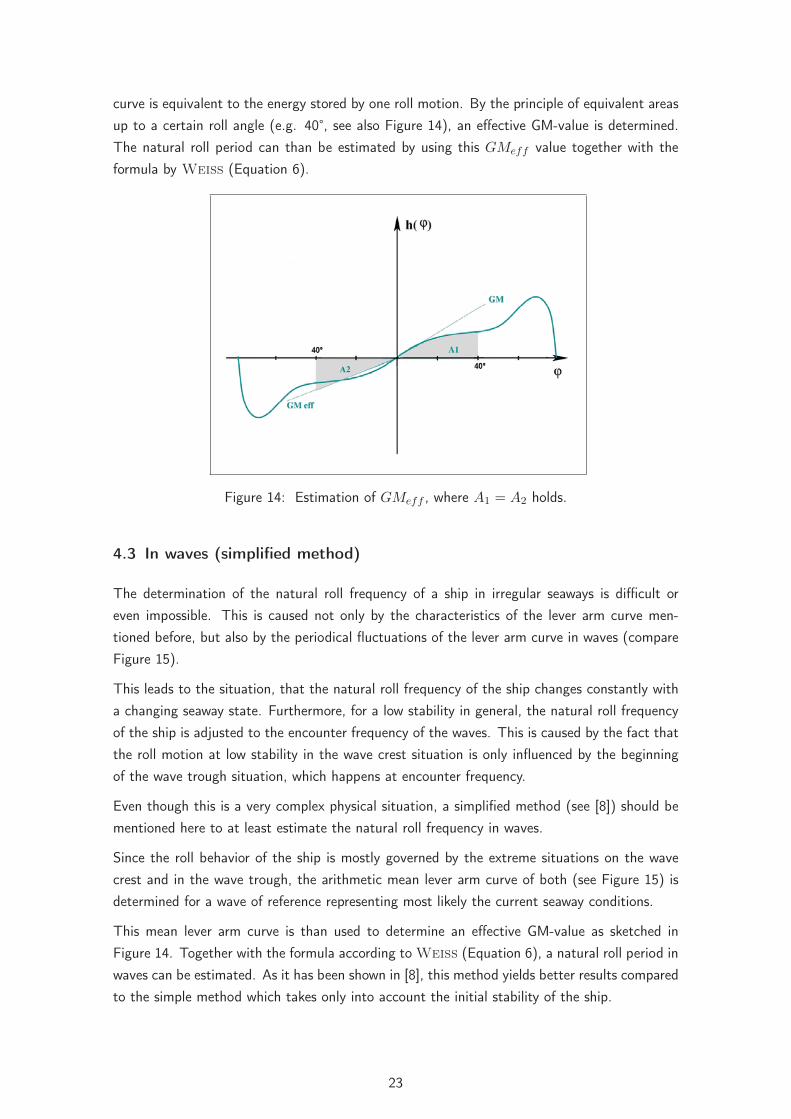
curve is equivalent to the energy stored by one roll motion. By the principle of equivalent areasup to a certain roll angle (e.g. 40°, see also Figure 14), an effective GM-value is determined.The natural roll period can than be estimated by using this GMeff value together with theformula by Weiss (Equation 6).
Figure 14: Estimation of GMeff , where A1 = A2 holds.
4.3 In waves (simplified method)
The determination of the natural roll frequency of a ship in irregular seaways is difficult oreven impossible. This is caused not only by the characteristics of the lever arm curve men-tioned before, but also by the periodical fluctuations of the lever arm curve in waves (compareFigure 15).
This leads to the situation, that the natural roll frequency of the ship changes constantly witha changing seaway state. Furthermore, for a low stability in general, the natural roll frequencyof the ship is adjusted to the encounter frequency of the waves. This is caused by the fact thatthe roll motion at low stability in the wave crest situation is only influenced by the beginningof the wave trough situation, which happens at encounter frequency.
Even though this is a very complex physical situation, a simplified method (see [8]) should bementioned here to at least estimate the natural roll frequency in waves.
Since the roll behavior of the ship is mostly governed by the extreme situations on the wavecrest and in the wave trough, the arithmetic mean lever arm curve of both (see Figure 15) isdetermined for a wave of reference representing most likely the current seaway conditions.
This mean lever arm curve is than used to determine an effective GM-value as sketched inFigure 14. Together with the formula according to Weiss (Equation 6), a natural roll period inwaves can be estimated. As it has been shown in [8], this method yields better results comparedto the simple method which takes only into account the initial stability of the ship.
23

Figure 15: Example for the estimation of a mean lever arm curve in waves
24

5 Assessing ship motions in waves by numerical simulations
with E4-ROLLS
To check whether the guidelines 707 and 1228 deliver reliable results, which means that dan-gerous situations can actually be avoided, numerical simulations for ships which definitivelycapsized were performed. The simulations were performed using the method E4ROLLS. Oneresult of E4ROLLS is a polar diagram that shows the significant wave height which is in anatural seaway required to fulfill a given criterion, e.g. capsizing. The following section brieflyintroduces E4ROLLS and the numerical model of the sea state.
5.1 Natural sea states
The natural sea state, short crested and irregular, is a stochastic process, which depends onseveral factors, such as wind force, fetch, water depth etc. According to the linear wave theory[10], the sea state can be created by superimposing elementary sine waves. These sine waveshave different frequencies and phase shifts. In reality, the assumption of sine waves may notbe valid, especially for short and steep waves. Here, the troughs are longer and the crests aresteeper compared to a sine wave. But if we consider waves of a certain length and steepness,the assumption is still valid. Breaking waves can of course not be described by that approach.
To generate short crested waves which better represent a natural sea state (compared to longcrested waves, see Fig. 16), the elementary waves are additionally distributed around theencounter angle (single peak spectrum). This is important for the simulations, because shipsin short crested seaways can behave completely different as in long crested waves, see. Fig. 17.The reason is that the different encounter angles of the different waves result in direct wavemoments, which are also introduced into the ship when it sails exactly in following seas. It isthis component which often initiates a roll motion, especially for small encounter angles aboutμ = 0°.
Figure 16: Long crested (left) and short crested waves (right) , from [10].
25

Figure 17: Example of polar plots for long crested waves (left) and short crested waves (right)for a roll angle of 50 °, from [11].
The individual seastates are described by their energy spectra, where the elementary waves areshown by their fraction of the total energy over their frequency. This spectrum is characterizedby a peak, which is quite narrow for a relatively regular seastate. In contradiction, the peakof the spectrum of an irregular seastate is not that pronounced. Information on the encounterangles of single components of that seastate are not contained in that spectrum, thereforeadditional information is required (e. g. the angular spreading of the components).
For the numerical description of the seastate, a JONSAWP- Spectrum see Fig. 18) is used,which is based on long term measurements in the North Sea. To generate a seastate froma JONSWAP- spectrum, the parameters (significant) wave height, significant wave length (orperiod) and encounter angle must be known. Using a number of several discrete components,the spectrum is approximated. Here, stripes of either constant frequency difference or constantenergy difference can be used. The latter is preferred due to that fact that the very high orvery low frequencies would be over represented in the seastate, otherwise. The quality of thenumerical seastate increases with the number of elementary components.
Figure 18: JONSWAP-Spectrum with constant energy abscissae, from [5].
26

5.2 The simulation method
The simulation code ROLLS was developed by Soeding and Kroeger for the analysis of thecapsizing accident of E.L.M.A. TRES in 1982. The method has been further developedand validated during several national BMBF- funded research projects and is now called E4-ROLLS. ROLLS was specially developed for problems in head seas or following seas. Themethod simulated all six degrees of freedom in time domain. For two degrees of freedom -roll and surge - the non linearities are found more important than the hydrodynamics, and forthese degrees of freedom a simulation approach is selected. For the other degrees of freedom,hydrodynamic effects are considered to be more important than non linearities, and a linearRAOs are used for these degrees of freedom. The equation for the roll motion reads:
ϕ̈ =
∑M − Md − m · (g − ζ̈) · hs − Θxz ·
[(ϑ̈ + ϑϕ̇2
)· sin ϕ −
(ψ̈ + ψϕ̇2
)· cos ϕ
]Θxx − Θxz · (ψ · sin ϕ + ϑ · cos ϕ)
(9)
where
∑M Sum of external moments due to wind, tanks, direct wave moment, etc.
Md non linear damping moment
ϕ, ϑ, ψ, ϕ̈, ϑ̈, ψ̈ Roll-, Pitch- and Yaw- angle and their accelerations
ζ̈ Heave acceleration
m Total mass
hs Righting lever
Θxx, Θxz Mass moments of inertia
The other four degrees of freedom are computed by linear RAOs. The coupling with the nonlinear motions is accounted for, see. eqn. 9). RAOs are computed by a linear strip methodusing Rankine- sources, based on a method by Yeung.
The righting levers of the ship (in waves) are computed using the concept of Grim’s equivalentwave, see Fig. 19. This makes the method extremely fast, especially in natural seastates withmany components. This makes it possible to study a large number of situations in quite a shorttime.
27

Figure 19: The equivalent wave, according to Grim, from [5].
Due to the linearization of the yaw motion, E4ROLLS con not compute broaching-to. Further,it is assumed that the roll motion is overpredicted for close to zero speed cases in beamseas, as the portion of the energy from the seastate which is transferred to the drift motionis underpredicted. These principal deficiencies of the method are not relevant for the casesstudied in this thesis, as all accidents happened in following or stern quartering seas, whereμ = 45°. For all the accidents examined, broaching-to was not the relevant failure mode.
Further details of the method E4ROLLS can be found in [18] or in [5].
28

6 Analysis and examination
6.1 Analyzed ships
A total number of 12 ships are analyzed. Eight of the analyzed cases are real capsizing accidentsand two are model analyses, for which the capsizing characteristics have been examined. Thelast two cases are ships which have lost containers during a journey. All of the examined acci-dents occurred in following or quartering seas. More details concerning the accident situationsand causes can be found in [11], [19] and [20].
The essential data of the vessels, the sailing and the environmental conditions during theaccidents can be found in table 5. Table 6 shows the stability data within the accident situations,a secure loading condition and the analyzed wave lengths. The wave length in accordance withthe accident situation is accented.
No. Name Year of accident Lpp [m] B [m] vs [kts] μ [°] TW [s] H 13
[m]
1 Fidamus 1950 55,90 8,20 9,5 22,5 5,0 2,0
2 Lohengrin 1963 59,65 9,60 10,0 15,0 6,0 2,0
3 Irene Oldendorf 1951 81,60 13,20 10,0 45,0 7,15 minimum5,0
4 Hoheneichen 1959 55,00 9,60 10,5 30,0 5,0 4,0
5 Wilhelm 1973 55,00 9,60 10,0 30,0 6,0 2,5 - 3,0
6 Halstenbek 1996 55,00 9,60 9,0 25 7,0 4,0 - 4,5
7 Finnbirch 2006 137,00 22,70 16,0 - 17,0 15 8,0 - 8,5 5,0 - 6,0
8 Cougar Ace 2006 190,00 32,26 18,6 10 9,1 - 10,8 3,0 - 4,0
9 Flower Class(Model test)
2005 189,70 26,50 12,0 5 11,47 8,8
10 SINBAD (Modeltest)
2005 156,00 28,00 6,5 and 16,0 5 10,17 8,4
11 JRS Canis 2007 120,34 20,60 15,5 45 10,0 - 11,0 6 - 8
12 Container Vessel 2004 244,80 32,24 21,0 10 9,0 - 10,5 6,5 - 7,0
Table 5: Data of the vessels, sailing and environmental conditions during the accidents.
29

No. Name GMAccident [m] GMsecure [m] i [−] λ [m]
1 Fidamus 0,298 0,700 0,38 32, 40 , 48
2 Lohengrin 0,130 0,314 0,38 48, 57 , 66
3 Irene Oldendorf 0,145 0,387 0,40 69, 80 , 92
4 Hoheneichen 0,391 0,946 0,38 32, 40 , 48
5 Wilhelm 0,476 0,953 0,38 48, 57 , 66
6 Halstenbek 0,720 0,969 0,39 66, 77 , 88
7 Finnbirch 1,690 1,900 0,38 88, 113 , 141
8 Cougar Ace 0,650 2,090 0,47 113, 141, 172 , 206
9 Flower Class(Model test)
1,040 1,490 0,42 206
10 SINBAD (Modeltest)
2,178 3,360 0,42 160
11 JRS Canis 1,410 - 0,39 141, 172 , 206
12 Container Vessel 0,95 - 0,42 141, 172 , 206
Table 6: Stability data and analyzed wave lengths
6.2 Procedural method
All of the examined accidents occurred in following or quartering seas, for this reason the anal-ysis only deals with this domain. Thereby the process sequence of guideline 707 described in3.4 is chosen, since the order in respect to the sub-criteria is reasonable. Because of this andthe fact that only following and quartering seas are examined, the above mentioned processsequence is also used for the evaluation of the effectiveness of the guideline 1228.
In order to get a basis of valuation various motion simulations in natural seaways for differentvelocities and encounter angles, in a range from μ = 0° to 90°, are executed for each vessel.This is done for different wave lengths as well, on one hand in order to reduce the uncertaintiesconcerning the informations about the wave periods (especially for the older accidents) and onthe other hand in order to cover the specified range of wave periods if applicable.
Furthermore the criterion for capsizing, respectively for the occurrence of the accident, is set toa roll angle exceeding ϕ = 50° or the roll angle at which the containers were lost. The resultsof these simulations are plotted in polar diagrams, where concentric semicircles comply withconstant speeds and orthogonal axes to the semicircles comply with constant encounter angles.The intersection points of these curves are the situations calculated within a simulation. Thesignificant wave height, at which the limiting criterion is reached, is marked by a color scale,where the minimum value is labeled pink and the maximum value refers to the color blue.
The natural roll periods of the vessels are calculated with the formula of Weiss (formula 6)and the initial stillwater GM -value, because this is closest to the recommended way in bothguidelines (cf.3.3). The velocities at which the 1:1- and 2:1-resonances appear are marked inthe polar diagrams according to the method introduced in SLF 44/INF.3 (see 3.5.1), though
30

only the speeds for resonances within the observed region are enlisted.
To evaluate the effectiveness of the guidelines 707 and 1228 an additional subscripted secureloading condition, according to [11], with higher stability is examined for each case wherecapsizing really occurred. For these secure loading conditions motion simulations with thesame wave length and sailing conditions are executed and analyzed. The above mentionedcriterion of failure stays the same.
6.3 Analysis
In the following subsections the guidelines are analyzed for the 12 vessels in detail. In theprocess the criterion K1 is not specified for each ship, but it is examined centralized for allvessels later. The reason for this is that the criterion for surf-riding and broaching-to does notplay a decisive role for any of the vessels ((see 6.4.1). Following no new conditions concerningthe ships velocities for the other criteria unfold.
Additionally it is checked for the accident condition what situation the guidelines would recom-mend and if these recommendations would have avoided the accident. The speed of the vesselfor the “secure” situation is determined in the way, that it is approximately one knot outside thedangerous zone in direction of the encounter angle. If the new velocity matches a predictionpoint for resonance by the guidelines, the velocity is further reduced by another knot. A changeof course of the vessel is not being analyzed.
Beside the polar diagrams for each vessel for the accident situation and the secure loadingcondition, the corresponding curves of righting arms within a reference wave, in accordancewith the seaway at the accident, are shown as well. From this it can be seen very clearly howthe increase of the stability effects the curves of righting arms positively.
31
6.3.1 Real capsizing accidents
6.3.1.1 FIDAMUS leer
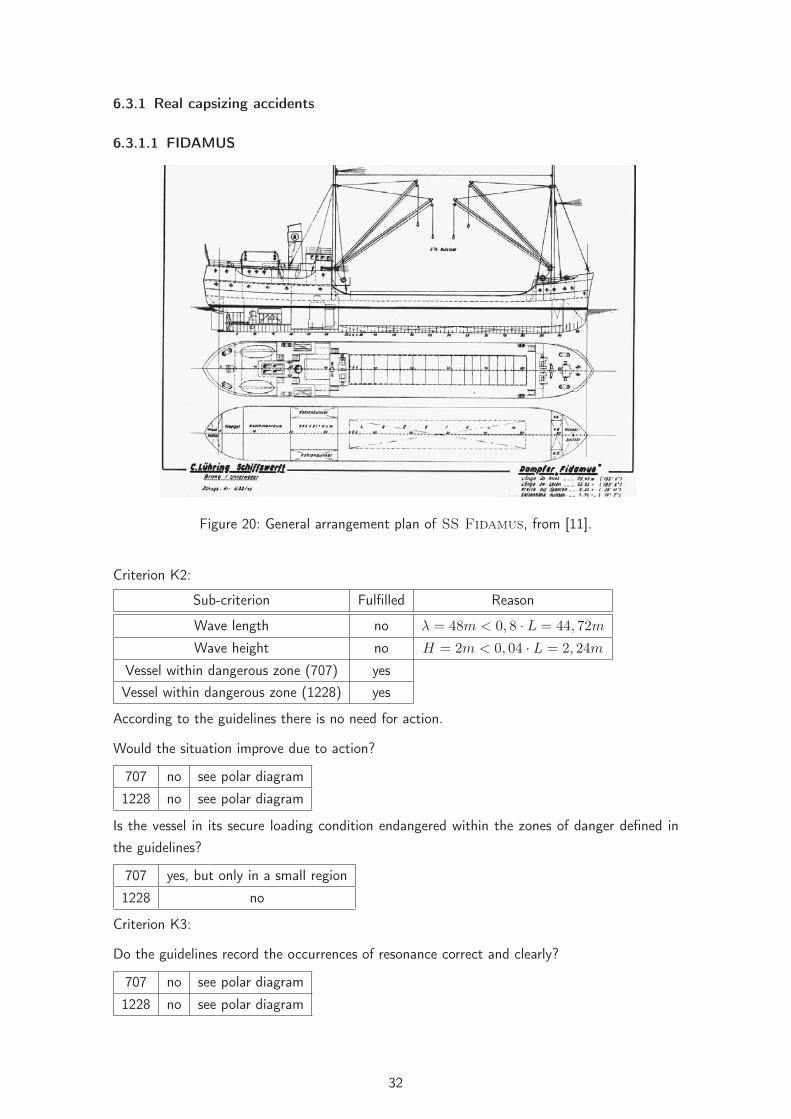
Figure 20: General arrangement plan of SS Fidamus, from [11].
Criterion K2:
Sub-criterion Fulfilled Reason
Wave length no λ = 48m < 0, 8 · L = 44, 72m
Wave height no H = 2m < 0, 04 · L = 2, 24m
Vessel within dangerous zone (707) yesVessel within dangerous zone (1228) yes
According to the guidelines there is no need for action.
Would the situation improve due to action?
707 no see polar diagram
1228 no see polar diagram
Is the vessel in its secure loading condition endangered within the zones of danger defined inthe guidelines?
707 yes, but only in a small region
1228 no
Criterion K3:
Do the guidelines record the occurrences of resonance correct and clearly?
707 no see polar diagram
1228 no see polar diagram
32

Summarization:
Would the accident have been avoided by application of the guidelines?
707 no because the vessel is consistently endangered within following seaway1228 no and the guidelines don’t recommend any action.
Additional polar diagrams can be found in appendix A.
Figure 21: Polar diagrams for the accident situation (top) and for the secure loading condition(bottom) of the Fidamus at a wave length of λ = 40 m (707 left-hand, 1228right-hand side of the polar diagrams).
33
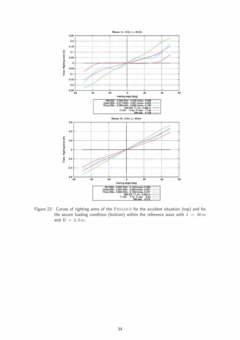
Figure 22: Curves of righting arms of the Fidamus for the accident situation (top) and forthe secure loading condition (bottom) within the reference wave with λ = 40mand H = 2, 0 m.
34

6.3.1.2 LOHENGRIN leer
Figure 23: Profile view of MV Lohengrin, from [11].
Criterion K2:
Sub-criterion Fulfilled Reason
Wave length yes λ = 57 m > 0, 8 · L = 47, 72m
Wave height no H = 2 m < 0, 04 · L = 2, 24 m
Vessel within dangerous zone (707) yesVessel within dangerous zone (1228) yes
According to the guidelines there is no need for action.
Would the situation improve due to action?
707 yes see polar diagram
1228 no see polar diagram
Is the vessel in its secure loading condition endangered within the zones of danger defined inthe guidelines?
707 no
1228 no
Criterion K3:
Do the guidelines record the occurrences of resonance correct and clearly?
707 yes, but not unambiguously see polar diagram
1228 yes, but not unambiguously see polar diagram
Summarization:
Would the accident have been avoided by application of the guidelines?
707 no because the guideline does not recommend any action
1228 no because the guideline does not recommend any action
Additional polar diagrams can be found in appendix B.
35

Figure 24: Polar diagrams for the accident situation (top) and the secure loading condition(bottom) of the Lohengrin at a wave length of λ = 57 m (707 left-hand, 1228right-hand side of the polar diagrams).
36

Figure 25: Curves of righting arms of the Lohengrin for the accident situation (top) andthe secure loading condition (bottom) within a reference wave with λ = 57 m andH = 2, 0 m.
37
6.3.1.3 IRENE OLDENDORF leer
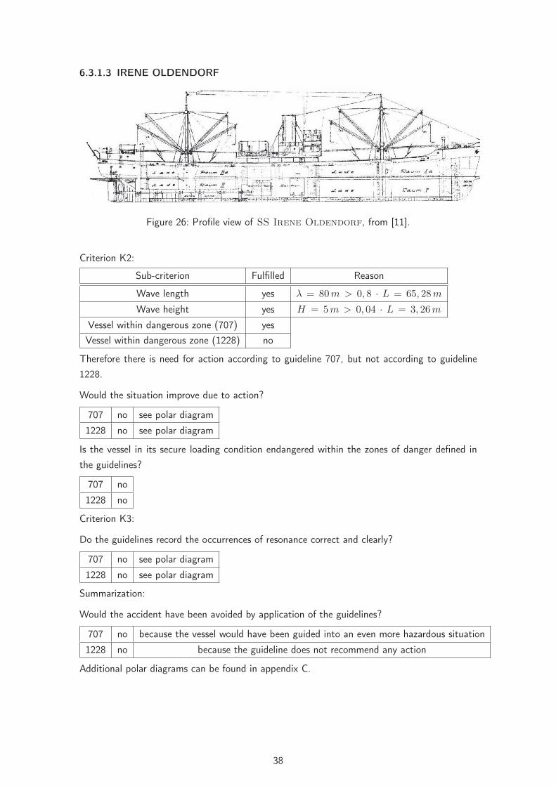
Figure 26: Profile view of SS Irene Oldendorf, from [11].
Criterion K2:
Sub-criterion Fulfilled Reason
Wave length yes λ = 80 m > 0, 8 · L = 65, 28 m
Wave height yes H = 5 m > 0, 04 · L = 3, 26 m
Vessel within dangerous zone (707) yesVessel within dangerous zone (1228) no
Therefore there is need for action according to guideline 707, but not according to guideline1228.
Would the situation improve due to action?
707 no see polar diagram
1228 no see polar diagram
Is the vessel in its secure loading condition endangered within the zones of danger defined inthe guidelines?
707 no
1228 no
Criterion K3:
Do the guidelines record the occurrences of resonance correct and clearly?
707 no see polar diagram
1228 no see polar diagram
Summarization:
Would the accident have been avoided by application of the guidelines?
707 no because the vessel would have been guided into an even more hazardous situation
1228 no because the guideline does not recommend any action
Additional polar diagrams can be found in appendix C.
38

Figure 27: Polar diagrams for the accident situation (top) and for the secure loading condition(bottom) of Irene Oldendorf at a wave length of λ = 80 m (707 left-hand,1228 right-hand side of the polar diagrams).
39

Figure 28: Curves of righting arms of Irene Oldendorf for the accident situation (top) andfor the secure loading condition (bottom) within the reference wave with λ = 80 mand H = 5, 0 m.
40

6.3.1.4 HOHENEICHEN leer
Figure 29: MV Hoheneichen completely loaded, from [11].
Criterion K2:
Sub-criterion Fulfilled Reason
Wave length no λ = 40 m < 0, 8 · L = 44, 00 m
Wave height yes H = 4 m > 0, 04 · L = 2, 20 m
Vessel within dangerous zone (707) yesVessel within dangerous zone (1228) yes
According to the guidelines there is no need for action.
Would the situation improve due to action?
707 no see polar diagram
1228 no see polar diagram
Is the vessel in its secure loading condition endangered within the zones of danger defined inthe guidelines?
707 no
1228 no
Criterion K3:
Do the guidelines record the occurrences of resonance correct and clearly?
707 no see polar diagram
1228 no see polar diagram
Summarization:
Would the accident have been avoided by application of the guidelines?
707 no because the guideline does not recommend any action
1228 no because the guideline does not recommend any action
Additional polar diagrams can be found in appendix D.
41

Figure 30: Polar diagrams for the accident situation (top) and the secure loading condition(bottom) of the Hoheneichen at a wave length of λ = 40 m (707 left-hand,1228 right-hand side of the polar diagrams).
42

Figure 31: Curves of righting arms of Hoheneichen for the accident situation (top) and thesecure loading condition (bottom) within the reference wave with λ = 40 m andH = 4, 0 m.
43
6.3.1.5 WILHELM leer
Figure 32: Profile view of MV Wilhelm, from [11].
Criterion K2:
Sub-criterion Fulfilled Reason
Wave length yes λ = 57 m > 0, 8 · L = 44, 00 m
Wave height yes H = 2, 5 m > 0, 04 · L = 2, 20 m
Vessel within dangerous zone (707) yesVessel within dangerous zone (1228) yes
Therefore there is need for action according to guidelines.
Would the situation improve due to action?
707 no see polar diagram
1228 no see polar diagram
Is the vessel in its secure loading condition endangered within the zones of danger defined inthe guidelines?
707 no
1228 no
Criterion K3:
Do the guidelines record the occurrences of resonance correct and clearly?
707 no see polar diagrams
1228 no see polar diagrams
Summarization:
Would the accident have been avoided by application of the guidelines?
707 no because the vessel is consistently endangered within following seaway
1228 no because the vessel is consistently endangered within following seaway
Additional polar diagrams can be found in appendix E.
44

Figure 33: Polar diagrams for the accident situation (top) and for the secure loading condition(bottom) of the Wilhelm at a wave length of λ = 57 m (707 left-hand, 1228right-hand side of the polar diagrams).
45

Figure 34: Curves of righting arm of the Wilhelm for the accident situation (top) and thesecure loading condition (bottom) within the reference wave with λ = 57 m andH = 2, 5 m.
46

6.3.1.6 HALSTENBEK leer
Figure 35: MV Halstenbek, from [11].
Criterion K2:
Sub-criterion Fulfilled Reason
Wave length yes λ = 77 m > 0, 8 · L = 44, 00 m
Wave height yes H = 4 m > 0, 04 · L = 2, 2 m
Vessel within dangerous zone (707) yesVessel within dangerous zone (1228) no
Therefore there is need for action according to guideline 707, but not according to guideline1228.
Would the situation improve due to action?
707 no see polar diagram
1228 no see polar diagram
Is the vessel in its secure loading condition endangered within the zones of danger defined inthe guidelines?
707 no
1228 no
Criterion K3:
Do the guidelines record the occurrences of resonance correct and clearly?
707 no detected 1:1-resonance at real 2:1-resonance (at approx. 4 kts),1228 no real 1:1-resonance at approx. 10 kts, see polar diagram
Summarization:
Would the accident have been avoided by application of the guidelines?
707 no because the vessel would have been guided into a likewise hazardous situation
1228 no because the guideline does not recommend any action
Additional polar diagrams can be found in appendix F.
47

Figure 36: Polar diagrams for the accident situation (top) and the secure loading condition(bottom) of the Halstenbek at a wave length of λ = 77 m (707 left-hand, 1228right-hand side of the polar diagrams).
48
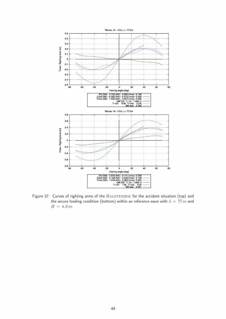
Figure 37: Curves of righting arms of the Halstenbek for the accident situation (top) andthe secure loading condition (bottom) within an reference wave with λ = 77 m andH = 4, 0 m.
49

6.3.1.7 FINNBIRCH leer
Figure 38: MV Finnbirch, [12].
Criterion K2:
Sub-criterion Fulfilled Reason
Wave length yes λ = 113 m > 0, 8 · L = 109, 60 m
Wave height yes H = 6 m > 0, 04 · L = 5, 48 m
Vessel within dangerous zone (707) yesVessel within dangerous zone (1228) yes
Therefore there is need for action according to the guidelines.
Would the situation improve due to action?
707 no see polar diagram
1228 no see polar diagram
Is the vessel in its secure loading condition endangered within the zones of danger defined inthe guidelines?
707 no
1228 no
Criterion K3:
Do the guidelines record the occurrences of resonance correct and clearly?
707 no see polar diagram
1228 no see polar diagram
Summarization:
Would the accident have been avoided by application of the guidelines?
707 no because the vessel would have been guided into a likewise hazardous situation
1228 no because the vessel would have been guided into a likewise hazardous situation
Additional polar diagrams can be found in appendix G.
50

Figure 39: Polar diagrams for the accident situation (top) and the secure loading condition(bottom) of the Finnbirch at a wave length of λ = 113 m (707 left-hand, 1228right-hand side of the polar diagrams).
51
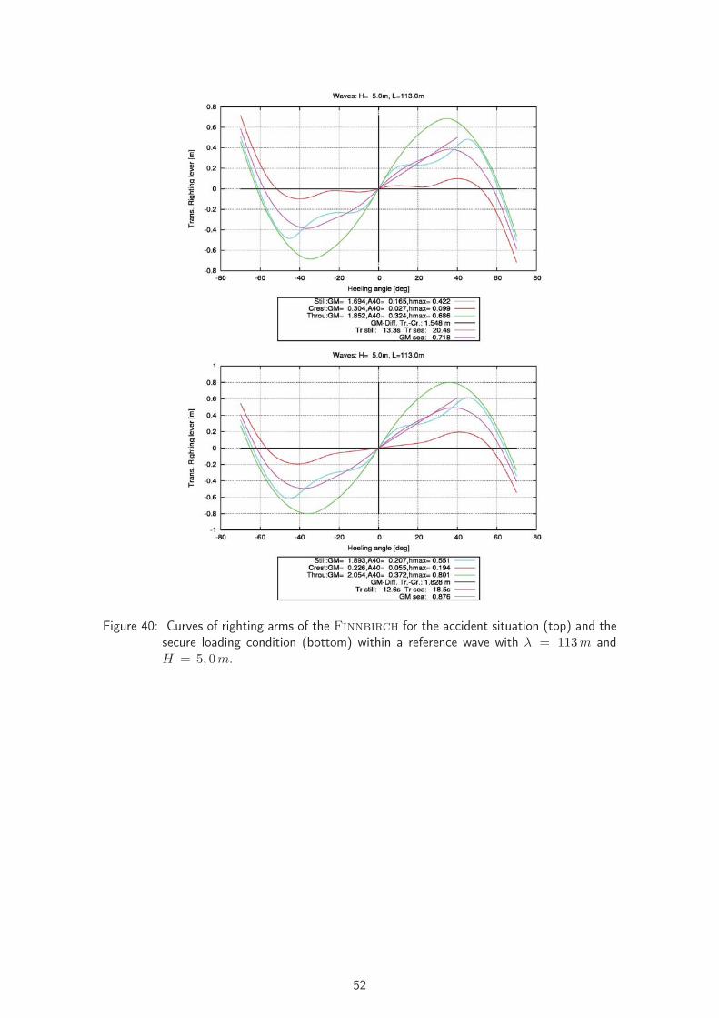
Figure 40: Curves of righting arms of the Finnbirch for the accident situation (top) and thesecure loading condition (bottom) within a reference wave with λ = 113 m andH = 5, 0 m.
52

6.3.1.8 COUGAR ACE leer
Figure 41: General arrangement plan of the M.V. Cougar Ace, from [11].
Criterion K2:
Sub-criterion Fulfilled Reason
Wave length yes λ = 172 m > 0, 8 · L = 152, 0 m
Wave height no H = 3 m < 0, 04 · L = 7, 6 m
Vessel within dangerous zone (707) yesVessel within dangerous zone (1228) yes
According to the guidelines there is no need for action.
Would the situation improve due to action?
707 no see polar diagram
1228 no see polar diagram
Is the vessel in its secure loading condition endangered within the zones of danger defined inthe guidelines?
707 no
1228 no
Criterion K3:
Do the guidelines record the occurrences of resonance correct and clearly?
707 no see polar diagram
1228 no see polar diagram
Summarization:
Would the accident have been avoided by application of the guidelines?
707 no because the guideline does not recommend any action
1228 no because the guideline does not recommend any action
Additional polar diagrams can be found in appendix H.
53

Figure 42: Polar diagrams for the accident situation (top) and the secure loading condition(bottom) of the Cougar Ace at a wave length of λ = 172 m (707 left-hand,1228 right-hand side of the polar diagrams).
54

Figure 43: Curves of righting arms of the Cougar Ace for the accident situation (top) andthe secure loading condition (bottom) within the reference wave with λ = 172 mand H = 3, 0 m.
55
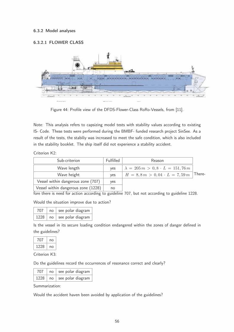
6.3.2 Model analyses
6.3.2.1 FLOWER CLASS leer
Figure 44: Profile view of the DFDS-Flower-Class RoRo-Vessels, from [11].
Note: This analysis refers to capsizing model tests with stability values according to existingIS- Code. These tests were performed during the BMBF- funded research project SinSee. As aresult of the tests, the stabiliy was increased to meet the safe condition, which is also includedin the stability booklet. The ship itself did not experience a stability accident.
Criterion K2:
Sub-criterion Fulfilled Reason
Wave length yes λ = 205 m > 0, 8 · L = 151, 76 m
Wave height yes H = 8, 8 m > 0, 04 · L = 7, 59 m
Vessel within dangerous zone (707) yesVessel within dangerous zone (1228) no
There-
fore there is need for action according to guideline 707, but not according to guideline 1228.
Would the situation improve due to action?
707 no see polar diagram
1228 no see polar diagram
Is the vessel in its secure loading condition endangered within the zones of danger defined inthe guidelines?
707 no
1228 no
Criterion K3:
Do the guidelines record the occurrences of resonance correct and clearly?
707 no see polar diagram
1228 no see polar diagram
Summarization:
Would the accident haven been avoided by application of the guidelines?
56

707 no because the vessel would have been guided into a likewise hazardous situation
1228 no because the guideline does not recommend any action
Figure 45: Polar diagram for the accident situation (top) and for the secure loading condition(bottom) of the Flower-Class vessels at a wave length of λ = 206 m (707left-hand, 1228 right-hand side of the polar diagrams).
57

Figure 46: Curves of righting arms of the Flower-Class vessels for the accident situation(top) and the secure loading condition (bottom) within the reference wave withλ = 206 m and H = 8, 8 m.
58

6.3.2.2 SINBAD leer
Figure 47: Hull form of the SINBAD-Model, from [11].
Note: This analysis refers to capsizing model tests with stability values according to existing IS-Code. These tests were performed during the BMBF- funded research project SinSee. This shipwas specially designed as a ship which fulfils all stability criteria, but is extremely vulnerable forcapsizing in following seas.
Criterion K2:
Sub-criterion Fulfilled Reason
Wave length yes λ = 160 m > 0, 8 · L = 124, 8 m
Wave height yes H = 8, 4 m > 0, 04 · L = 6, 24 m
Vessel within dangerous zone (707) yesVessel within dangerous zone (1228) yes
Therefore there is need for action according to the guidelines.
Would the situation improve due to action?
707 no recommended situation actually matches exactly the analyzed accident situationat 6,5 kts, see polar diagram
1228 no see polar diagram
Is the vessel in its secure loading condition endangered within the zones of danger defined inthe guidelines?
707 no
1228 no
Criterion K3:
Do the guidelines record the occurrences of resonance correct and clearly?
707 no see polar diagram
1228 no see polar diagram
Summarization:
Would the accident have been avoided by application of the guideline?
707 no because the vessel would have been guided into a likewise hazardous situation
1228 no because the vessel would have been guided into a likewise hazardous situation
59

Figure 48: Polar diagrams for the accident situation (top) and for the secure loading condition(bottom) of the SINBAD-Model at a wave length of λ = 160 m (707 left-hand,1228 right-hand side of the polar diagrams).
60
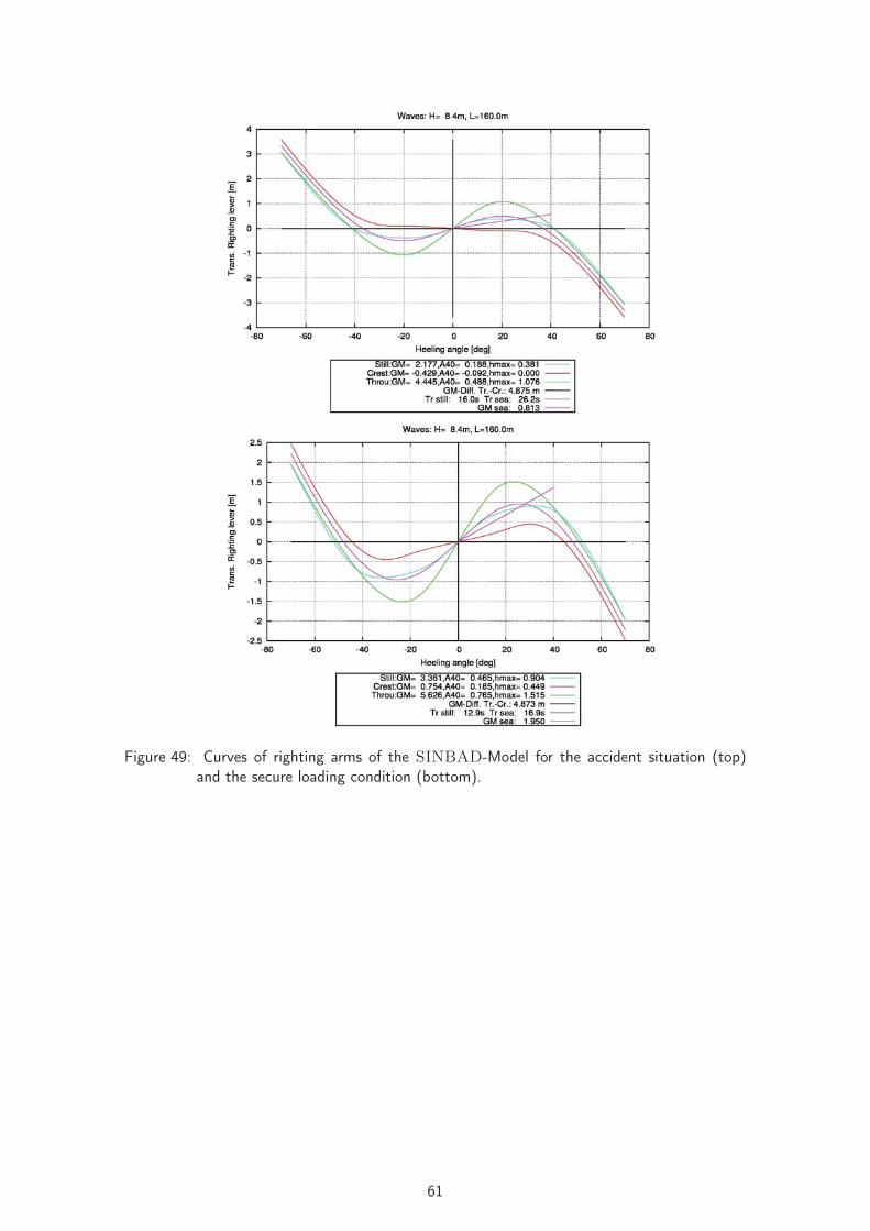
Figure 49: Curves of righting arms of the SINBAD-Model for the accident situation (top)and the secure loading condition (bottom).
61

6.3.3 Other accidents
For the following two accidents, concerning the loss of containers, no secure loading conditionshave been examined, because both vessels were not endangered by capsizing and thereforeminor stability was not the governing problem.
6.3.3.1 JRS CANIS leer
Figure 50: C.V. JRS Canis, [13].
Criterion K2:
Sub-criterion Fulfilled Reason
Wave length yes λ = 172 m > 0, 8 · L = 96, 27 m
Wave height no H = 6 m > 0, 04 · L = 4, 81 m
Vessel within dangerous zone (707) yesVessel within dangerous zone (1228) no
Therefore there is need for action according to guideline 707, but not according to guideline1228.
Would the situation improve due to action?
707 no see polar diagram
1228 no see polar diagram
Criterion K3:
Do the guidelines record the occurrences of resonance correct and clearly?
707 no see polar diagram
1228 no see polar diagram
Summarization:
Would the accident have been avoided by application of the guidelines?
707 no because the vessel would have been guided into a likewise hazardous situation
1228 no because the guideline does not recommend any action
62

Additional polar diagrams can be found in appendix I.
Figure 51: Polar diagram for the accident situation of the JRS Canis at a wave lengthof λ = 172 m (707 left-hand, 1228 right-hand side of the polar diagrams) for amaximum roll angle of ϕ = 20 °.
Figure 52: Curves of righting arms of the JRS Canis for the accident situation within anreference wave with λ = 172 m and H = 7, 0 m.
63

6.3.3.2 Container Vessel leer
Figure 53: Container Vessel, [14].
Criterion K2:
Sub-criterion Fulfilled Reason
Wave length no λ = 172 m < 0, 8 · L = 195, 84 m
Wave height no H = 7 m < 0, 04 · L = 9, 79 m
Vessel within dangerous zone (707) yesVessel within dangerous zone (1228) yes
According to the guidelines there is no need for action.
Would the situation improve due to action?
707 no see polar diagram
1228 no see polar diagram
Criterion K3:
Do the guidelines record the occurrences of resonance correct and clearly?
707 no see polar diagram
1228 no see polar diagram
Summarization:
Would the accident have been avoided by application of the guidelines?
707 no because the guideline does not recommend any action
1228 no because the guideline does not recommend any action
Additional polar diagrams can be found in appendix J.
64

Figure 54: Polar diagram for the accident situation of the Container Vessel at a wavelength of λ = 172 m (707 left-hand, 1228 right-hand side of the polar diagrams)for a maximum roll angle of ϕ = 15 °.
Figure 55: Curves of righting arms of the Container Vessel for the accident situationwithin a reference wave with λ = 172 m and H = 7, 0 m.
65

6.4 Summarization
6.4.1 Criterion for surf-riding and broaching-to (K1)
The analysis of the twelve accident situations regarding to the criterion K1 shows, that allvessels in all cases have been outside the dangerous zone defined by the guidelines. This canbe seen very clearly in figure 56.
Figure 56: Illustration regarding the analysis of criterion K1 in summary (707 left-hand, 1228right-hand side of the polar diagram).
66

6.4.2 Criterion for successive high wave attack (K2)
In figure 57 the positions of the vessels are shown regarding to the dangerous zones defined bythe criterion K2 of both guidelines. Furthermore the colors of the position marks demonstrate,if the sub-criteria, regarding to the required wave length and height, are fulfilled (red cross) ornot (green cross).It becomes apparent that there are more cases classified endangered by the guideline 707 becauseof its larger dangerous zone. Nevertheless not all vessels are classified endangered even thougha latent danger can be taken for granted for all accident situations.The picture changes if the secure loading conditions are taken as a basis. In these cases theclassification regarding to the criterion K2 of the accident situations do not change, as can beseen in figure 57, because the stability of the ships is not accounted for at all. For this reasonsome vessels would be classified endangered, even though there are no concrete threats.
Figure 57: Illustration regarding the analysis of criterion K2 in summary (707 left-hand, 1228right-hand side of the polar diagram).
6.4.3 Criterion for synchronous rolling and parametric rolling motions (K3)
Due to the analyes concerning the criterion K3 for the examined cases it can be seen veryclearly, that in all the cases the occurrences of resonance are not detected correctly.Furthermore there are no explicit resonance phenomena in most cases, because the vessels areendangered throughout a larger speed range.
67

7 Shortcomings of the guidelines
The analysis of the validity of the guidelines MSC/Circ. 707 and MSC.1/Circ. 1228 for theexamined cases leads to the conclusion, that for exactly none of the examined situations animprovement by the application of the criteria would be achieved. The shortcomings of theguidelines come, on the one hand, from the different criteria itselves and, on the other hand,from the recommended ways for the determination of the data which are necessary for the useof the criteria. Each of the three criteria, on which both guidelines are based upon, shall beexplained and evaluated in the following.
7.1 Successive high wave attack (K2)
The evaluation of the criterion K2 corresponds to the successive high wave attack. A course ofaction is only recommended by the guidelines, if three rated factors come together at one pointof time. These factors are: location within the danger zone, wave length and wave height.The analysis shows that the examined vessels definitely have been endangered, even though notall of the three factors come together. Following from this it can be stated that the guidelinesdo not recognize hazardous situations at all times. At this point a shortcoming of guideline707 is the definition of the danger zone depending on the ratio of the ship’s velocity to thewave period. The level of hazard to a ship is depending on the stability and not on the ratiodefined in the guideline. Following from the analysis it can be seen on the one hand, that shipsmay be in very severe situations even though the vessels are not located within the dangerouszone defined in the guidelines. On the other hand there are situations at which the guidelinesrecommend action, even though there is no hazard to the ship at a level of sufficient stability.Besides the above mentioned factors it is stated in the guidelines, that a dangerous behavior ofthe vessel has to be clearly observable in order to deduce a code of action. But it is very wellknown from various accidents, that there was no evidence for the endangerment of the vessel fora long time before the accident situation. However, at the first signals for a hazardous behaviorof the ships the threat is already at hand and there is no time left to anticipate the accident.The reason for this is the random behavior of natural sea ways leading to constellations ofwaves which may be extremely dangerous for ships.
7.2 Synchronous rolling and parametric rolling motions (K3)
The identification of dangerous resonances for rolling motions is behold of the criterion K3in the guidelines. During the analysis of the examined accidents no correlation between thepredicted resonances for the rolling motion according to the guidelines and the truly appearedcases was noticed. This identification can be extended to the effect that the endangermentexists over a large speed range, so that it is not valid to call it an explicit resonance situation.This is likewise true for the 1:1- und den 2:1-resonance situation. The reason for this is themode of determination of the period of roll recommended in the guidelines. According to theguidelines the period of roll for large rolling angles may be estimated through the linearization
68
of the initial stability of the still water curve of righting arms. This leads to wrong results forships sailing in waves (see 4). Additionally the determination can not be done as recommendedin the guidelines, since the natural period of roll of a ship changes due to lever arm alterations,especially for ships in conditions with low stability, in relation to the present excitation periodof the waves. For all examined capsizing accidents conditions of low stability were given andthe effect of adjustment to the excitation period can clearly been seen in the polar diagramsfor the accident situations.
7.3 Surf-riding and broaching-to (K1)
Finally the criterion K1 remains, which covers the danger of surf-riding and broaching-to of aship. This shall be mentioned here for the sake of completeness, since in none of the examinedcases a hazard to a vessel was caused by one of the two phenomena. Practically there is noevidence or indication that surf-riding or broaching-to have endangered the vessels at the timesof the accidents. If at all broaching-to occurred after the first heavy roll motion. As well theapplication of the guidelines to each examined case leads to the conclusion, that the vesselshave never been within the danger zone defined by the criterion K1. Therefore there is noevaluation possible for the examined cases at this point. Furthermore the danger of broaching-to can rather be determined related to the course-keeping ability of a ship and not related tothe examined stability.
Summing up it can be emphasized as shortcoming of the guidelines, that the sea-keepingperformance of each vessel as well as the different phenomena and their causes, which can leadto hazardous situations, are not responded to close enough. Only a good understanding ofthe different phenomena leads the ship’s command into the position of rating each particularsituation correctly and therefore enables them to operate the ship safely.
7.4 Statements towards the validity of the guidelines
Basically there are statements within the guidelines regarding the different sea-keeping behaviorof ships with the conclusion and the advice, that a universal validity towards a course of actionand its effectivity is not possible (Section 2.1 in [16] and Section 1.3 and 2 in [6]). For thisreason one major shortcoming is certainly to try to give a course of action anyway.
69

8 Summary
Scope of the present work is to check the reliability of the guidelines MSC/Circ. 707 resp.MSC.1/Circ. 1228. For several capsizing accidents it is analyzed whether the application ofthe guidelines would have avoided these accidents. Eight capsizing accidents, two accidentswhere containers were lost and two model test capsizings were studied, which all took place infollowing seas. The guidelines were applied to these cases. It was found that in none of theinvestigated cases, the guidelines would have delivered information which had helped to avoidthe accidents. This is due to present deficiencies of the guidelines, and it can be stated thatcomparable results would also be obtained, if the guidelines would be applied to other stabilityaccidents in following seas.
The main findings can be summarized as follows:
The guidelines take into account criteria for the determination of potentially dangerous situa-tions which are not relevant for the real behaviour of ships in following seas.
This leads to the fact that a dangerous zone identified by the guidelines is not necessarily anindication for a real danger. Depending on the individual stability of the ship, the real dangeroussituation may be outside the zone as identified by the guideline or may even not exist. In bestcase, counter measures are suggested which are unnecessary, because no real danger exists.But it is also well possible that counter measures suggested by the guidelines will bring the shipinto a real danger or into a situation which is more dangerous than before.
The simplifications of the physical effects made in the guidelines make the application on boardquite easy. But these simplifications lead to incorrectly reflected physical phenomena, whichleads to incorrect results and to the risk of not identifying dangerous situations in the majorityof applications.
To put it softly: The application of the guidelines is comparable to gambling, as the obtainedresults are incorrect or misleading in the majority of applications.
70
References
[1] www.containerhandbuch.de/chb/stra/index.html?/chb/stra/stra_02_03_03.
html. (24.09.2010)
[2] www.voranker.de/pages/seemanns-welt/monsterwellen/seeschlag.php.(24.09.2010)
[3] www.commons.wikimedia.org/wiki/File:Cougar_Ace_on_side_(starboard_side)
.jpg. (24.09.2010)
[4] www.voranker.de/pages/seemanns-welt/monsterwellen/parametric-rollings.
php. (24.09.2010)
[5] Kluwe, F.: Development of a Minimum Stability Criterion to Prevent Large AmplitudeRoll Motions in Following Seas. In: Dissertation, TUHH (2010)
[6] IMO: MSC/Circ. 707, GUIDANCE TO THE MASTER FOR AVOIDING DANGEROUSSITUATIONS IN FOLLOWING AND QUARTERING SEAS. (19. October 1995)
[7] IMO: SLF 44/INF.3, ANY OTHER BUSINESS Guidance to the Master for avoidingdangerous situations in following and quartering seas. (13 June 2001)
[8] Krüger, S. ; Kluwe, F.: A Simplified Method for the Estimation of the Natural RollFrequency of Ships in Heavy Weather. In: HANSA Bd. 145 (2008)
[9] N.N.: Richtlinien für die Überwachung der Schiffsstabilität. (Status 14.04.2003)
[10] Söding, H.: Bewegungen und Belastungen der Schiffe im Seegang. Hamburg. In: Vor-lesungsskript Nr 18, Institut für Schiffbau der Universität Hamburg (September 1982)
[11] Krüger, S. ; Kluwe, F.: Development of Threshold Values for a Minimum StabilityCriterion based on Full Scale Accidents. In: Schriftenreihe Schiffbau (March 2010)
[12] www.safeair.dk/graphics/interface/pic_587.jpg. (24.09.2010)
[13] www.ijmond.web-log.nl/photos/uncategorized/2009/02/26/1jrs_canis_mc.
jpg. (24.09.2010)
[14] www.flotilla-australia.com/images. (24.09.2010)
[15] BSU: Untersuchungsbericht 510/08, Tödlicher Personenunfall an Bord des CMSCHICAGO EXPRESS während des Taifuns "HAGUPIT" am 24. September 2008 im Seege-biet vor Hongkong. (1. November 2009)
[16] IMO: MSC.1/Circ. 1228, REVISED GUIDANCE TO THE MASTER FOR AVOIDINGDANGEROUS SITUATIONS IN ADVERSE WEATHER AND SEA CONDITIONS. (11.January 2007)
[17] IMO: SLF 48/4/8, REVISION OF THE CODE ON INTACT STABILITY Proposed revi-sion of MSC/Circ.707. (10. June 2005)
[18] Söding, H.: Simulation der Bewegungen intakter und lecker Schiffe. In: 23. Fortbil-
71

dungskurs, Institut für Schiffbau der Universität Hamburg (1987)
[19] BSU: Untersuchungsbericht 45/7, Verlust von 10 Containern von Bord der JRS CANISin der Elbmündung am 12. Januar 2007 um 2:40 Uhr. (1. Oktober 2008)
[20] Krüger, S.: Evaluation of the cargo loss of a large container vessel due to parametricroll. In: Proceedings of the the Ninth International Maritime Design Conference (2006)
[21] Boie, C.: Gedanken zur Sicherheit gegen Kentern. Hamburg. In: HANSA Nr. 18 (1962)
[22] Jensen, G.: Schiffe im Seegang II. In: Vorlesungsskript WS 06/07, TU Hamburg-Harburg(WS 06/07)
[23] Krüger, S.: Zur Frage des Erkennens von gefährlich großen Rollwinkeln im praktischenBordbetrieb. In: HANSA No. 9 (2006)
72

Appendix
In the following appendices more polar diagrams to each ship can be found.
73

AFID
AM
US
Pola
rdi
agra
ms
for
the
acci
dent
situ
atio
n(t
op)
and
for
the
secu
relo
adin
gco
nditi
on(b
otto
m)
ofth
eFidam
us
ata
wav
ele
ngth
ofλ
=32
m(lef
t),
λ=
40m
(mid
dle)
and
λ=
48m
(rig
ht).
74

BLO
HEN
GRIN
Pola
rdi
agra
ms
for
the
acci
dent
situ
atio
n(t
op)
and
for
the
secu
relo
adin
gco
nditi
on(b
otto
m)
ofth
eLohengrin
ata
wav
ele
ngth
ofλ
=48
m(lef
t),
λ=
57m
(mid
dle)
and
λ=
66m
(rig
ht).
75

CIR
EN
EO
LD
EN
DO
RF
Pola
rdi
agra
ms
for
the
acci
dent
situ
atio
n(t
op)
and
for
the
secu
relo
adin
gco
nditi
on(b
otto
m)
ofth
eIrene
Oldendorf
ata
wav
ele
ngth
ofλ
=69
m
(lef
t),λ
=80
m(m
iddl
e)an
dλ
=92
m(r
ight
).
76

DH
OH
EN
EIC
HEN
Pola
rdi
agra
ms
for
the
acci
dent
situ
atio
n(t
op)
and
for
the
secu
relo
adin
gco
nditi
on(b
otto
m)
ofth
eH
oheneichen
ata
wav
ele
ngth
ofλ
=32
m(lef
t),
λ=
40m
(mid
dle)
and
λ=
48m
(rig
ht).
77
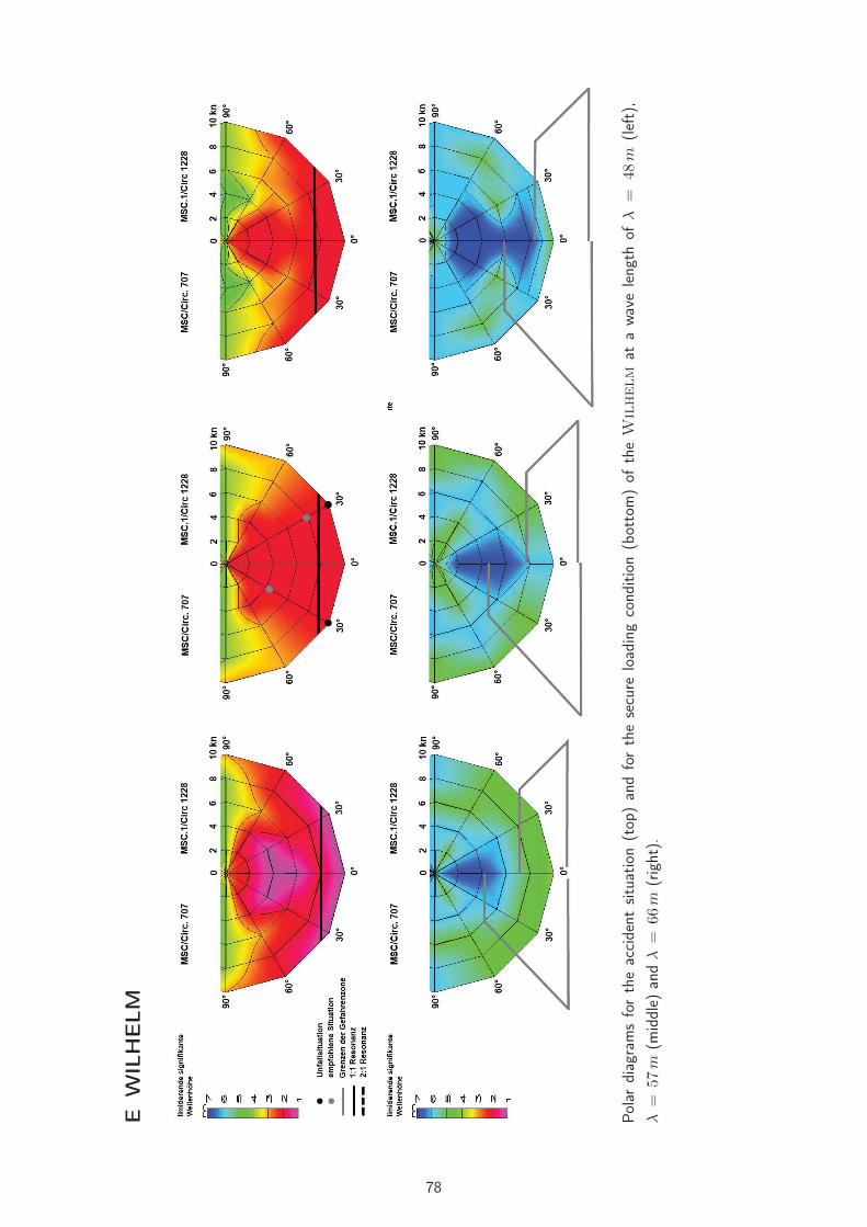
EW
ILH
ELM
Pola
rdi
agra
ms
for
the
acci
dent
situ
atio
n(t
op)
and
for
the
secu
relo
adin
gco
nditi
on(b
otto
m)
ofth
eW
ilhelm
ata
wav
ele
ngth
ofλ
=48
m(lef
t),
λ=
57m
(mid
dle)
and
λ=
66m
(rig
ht).
78

FH
ALST
EN
BEK
Pola
rdi
agra
ms
for
the
acci
dent
situ
atio
n(t
op)
and
for
the
secu
relo
adin
gco
nditi
on(b
otto
m)
ofth
eH
alstenbek
ata
wav
ele
ngth
ofλ
=66
m(lef
t),
λ=
77m
(mid
dle)
and
λ=
88m
(rig
ht).
79

GFIN
NB
IRCH
Pola
rdi
agra
ms
for
the
acci
dent
situ
atio
n(t
op)
and
for
the
secu
relo
adin
gco
nditi
on(b
otto
m)
ofth
eFinnbirch
ata
wav
ele
ngth
ofλ
=88
m(lef
t),
λ=
113
m(m
iddl
e)an
dλ
=14
1m
(rig
ht).
80
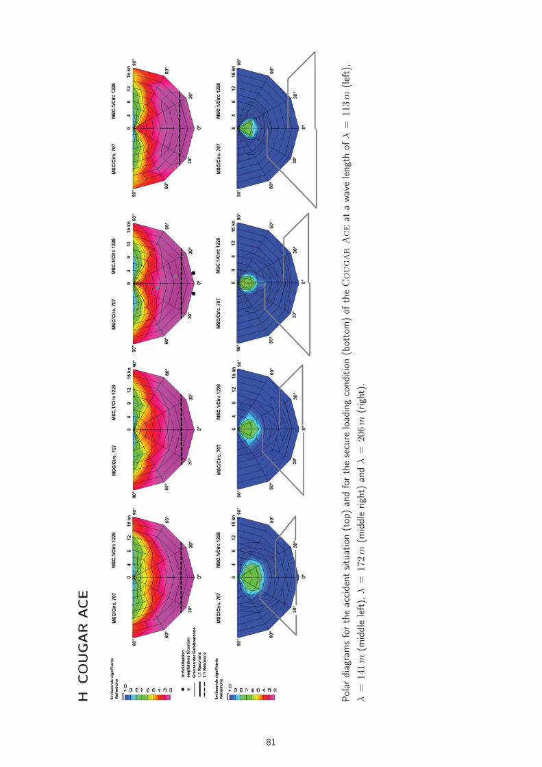
HCO
UG
AR
ACE
Pola
rdi
agra
ms
for
the
acci
dent
situ
atio
n(t
op)
and
for
the
secu
relo
adin
gco
nditi
on(b
otto
m)
ofth
eC
ougar
Ace
ata
wav
ele
ngth
ofλ
=11
3m
(lef
t),
λ=
141
m(m
iddl
ele
ft),
λ=
172
m(m
iddl
erig
ht)
and
λ=
206
m(r
ight
).
81
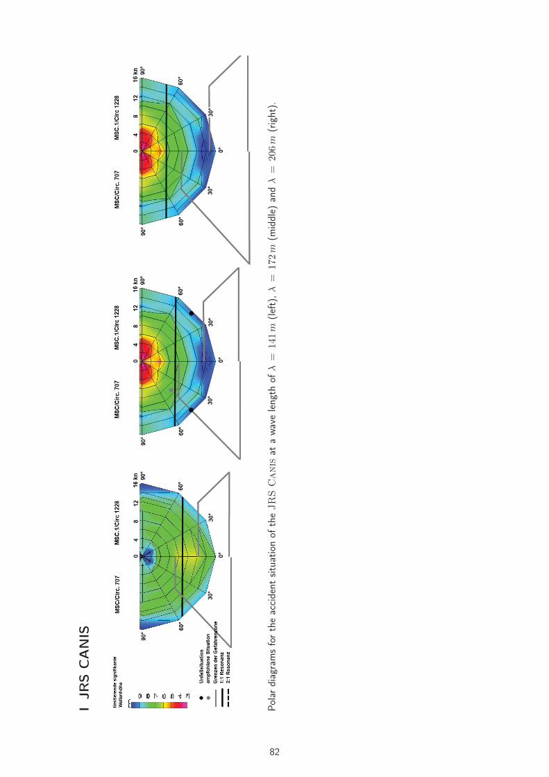
IJRS
CA
NIS
Pola
rdi
agra
ms
for
the
acci
dent
situ
atio
nof
the
JR
SC
anis
ata
wav
ele
ngth
ofλ
=14
1m
(lef
t),λ
=17
2m
(mid
dle)
and
λ=
206
m(r
ight
).
82

JConta
iner
Vess
el
Pola
rdi
agra
ms
forth
eac
cide
ntsitu
atio
nof
the
Container
Vessel
ata
wav
ele
ngth
ofλ
=14
1m
(lef
t),λ
=17
2m
(mid
dle)
and
λ=
206
m(r
ight
).
83