Embed Size (px)
Citation preview

Development of templates for protective
relays in design tool E3
Axel Lindfors
Bachelor’s thesis
Electrical Engineering
Vaasa 2014

Abstract
Author: Axel Lindfors
Degree Programme: Electrical Engineering
Specialization: Electrical Power Engineering
Supervisor: Roger Mäntylä
Title: Development of templates for protective relays in design tool E3
_________________________________________________________________________
2 March 2014 32 pages 9 Appendices
_________________________________________________________________________
This Bachelor’s thesis work was done for ABB Power Generation Systems in Vaasa. The
objective of this thesis work was to create ready-made templates in design tool E3,
containing all key schematics associated with a protection cubicle. As the design tool E3
has only recently been taken into use by the entire staff at Power Generation, another
objective was to try and find a unified layout for how the protection schematics could be
drawn. The main focus was on generator protection relays, but also other types were
evaluated. The resulting templates will be of use for both the design department and the
sales department when negotiating with clients.
The results of this work were five separate protective relay templates, four of which were
made for generator protection and one was for transformer protection. All of these
templates were then distributed through the E3 sub-circuit library to all users of the E3
design tool within the Power Systems division.
_________________________________________________________________________
Language: English
Key words: protective relay, E3, template
_________________________________________________________________________
Abstrakt
Författare: Axel Lindfors
Utbildningsprogram och ort: Elektroteknik, Vasa
Inriktningsalternativ: Elkraftsteknik
Handledare: Roger Mäntylä
Titel: Development of templates for protective relays in design tool E3
_________________________________________________________________________
2 mars 2014 32 sidor 9 Bilagor
_________________________________________________________________________
Detta examensarbete gjordes åt ABB Power Generation Systems i Vasa. Målet var att
skapa färdiga mallbottnar i planeringsverktyget E3, innehållande alla relevanta samt viktiga
elritningar tillhörande ett skyddsreläskåp. Eftersom planeringsverktyget E3 först nyligen
tagits i bruk av all personal vid Power Generation, så sattes det tid på att finna ett enhetligt
sätt att rita skyddskretsscheman. Huvudsakligen sattes fokus på generatorskyddsrelän, även
om andra alternativ undersöktes. De resulterande mallbottnarna skulle sedan komma i
användning för både planeringsavdelningen samt för försäljningen då de förhandlar med
kunder.
Resultatet för detta arbete blev fem olika skyddsrelämallbottnar, fyra specificerade för
generatorskydd och en för transformatorskydd. Alla mallbottnar spreds via E3:s ”sub-
circuit” databas till alla användare av E3-planeringsverktyget inom Power Systems
divisionen.
________________________________________________________________________
Språk: engelska
Nyckelord: skyddsrelä, E3, mallbotten
_________________________________________________________________________

Tiivistelmä
Tekijä: Axel Lindfors
Koulutusohjelma ja paikkakunta: Sähkötekniikka, Vaasa
Suuntautumisvaihtoehto: Voimasähkötekniikka
Ohjaajat: Roger Mäntylä
Nimike: Development of templates for protective relays in design tool E3
_________________________________________________________________________
2. maaliskuuta 2014 32 sivua 9 Liitettä
_________________________________________________________________________
Tämä opinnäytetyö tehtiin ABB Power Generation Systemsille Vaasassa. Työssä tehtävä
oli luoda valmiita tyyppipiirejä E3-suunnitteluohjelmaan, jotka sisältäisivät kaikki
oleellisimmat kaaviot liittyen suojarelekaapin suunnitteluun. Koska E3-suunnitteluohjelma
on vasta äskettäin otettu käyttöön koko Power Generation henkilöstön voimin, ajatuksena
oli myös yrittää yhtenäistää tapa, jolla suojauskaaviot piirretään. Pääpaino oli
generaattorisuojareleissä, mutta myös muita suojareleitä tutkittiin. Valmiit tyyppipiirit
tulisivat käyttöön suunnitteluosastolle sekä myyntiosastolle, kun neuvotteluja asiakkaiden
kanssa käydään.
Opinnäytetyön lopputulos oli viisi erillistä suojareletyyppipiiriä, neljä
generaattorisuojaukseen tarkoitettua ja yksi muuntajasuojaukseen. Kaikki tyyppipiirit
jaetiin E3 ”sub-circuit”-tietokannan kautta kaikille E3-käyttäjille, jotka kuuluvat Power
Systems divisioonaan.
_________________________________________________________________________
Kieli: Englanti
Avainsanat: suojarele, E3, tyyppipiiri
_________________________________________________________________________

Table of Contents Introduction ........................................................................................................................... 1
1.1 Company ............................................................................................................. 1
1.2 Purpose ................................................................................................................ 2
2 Protective relays ............................................................................................................ 3
2.1 History of protective relays ................................................................................. 3
2.2 The purpose and tasks of protective relays ......................................................... 5
2.3 Technical aspects of protective relays ................................................................. 7
2.4 Measuring transformers....................................................................................... 7
2.5 Protection functions in protective relays ............................................................. 8
2.5.1 Differential protection ..................................................................................... 9
2.5.2 Pole-slipping protection ................................................................................. 10
2.5.3 Overload protection ....................................................................................... 10
.5.4 Negative phase sequence protection .............................................................. 11
2.5.5 Reverse power protection .............................................................................. 11
2.6 Protection philosophy ........................................................................................ 13
3. E3 series ....................................................................................................................... 14
3.1 The developers .................................................................................................. 15
3.2 Modules ............................................................................................................. 16
3.2.1 E3 schematic .................................................................................................. 16
3.2.2 E3 panel ......................................................................................................... 16
4 Designing of the standardized template....................................................................... 17
4.1 Choice of protective relays ................................................................................ 17
4.2 Designing and drawing of the schematics ......................................................... 19
4.2.1 Single line diagram ........................................................................................ 19
4.2.2 Protection matrix ........................................................................................... 20
4.2.3 Supply circuits ............................................................................................... 21
4.2.4 Measurement circuits ..................................................................................... 22
4.2.5 Tripping circuits ............................................................................................ 22

4.2.6 Digital inputs/outputs .................................................................................... 23
4.2.7 Layout ............................................................................................................ 24
4.2.8 Reference tables ............................................................................................. 25
4.2.9 Lists and tables .............................................................................................. 26
4.3 Referencing of the inputs .................................................................................. 27
5 Results ......................................................................................................................... 29
6 Discussion .................................................................................................................... 30
References ........................................................................................................................... 31

Appendices
APPENDIX 1 – Protective SLD for a generator protection case
APPENDIX 2 – Protective SLD for a transformer protection case
APPENDIX 3 – Protection Matrix for the REG670 protective relay
APPENDIX 4 – Supply circuit schematic
APPENDIX 5 – Measurement circuit schematic
APPENDIX 6 – Tripping circuit schematic
APPENDIX 7 – Digital input schematic
APPENDIX 8 – Layout schematic of the REG670 protective relay
APPENDIX 9 – Connection terminal table

Abbreviations
AC – Alternating Current
DC – Direct Current
CAD – Computer-Aided Design
CB – Circuit Breaker
CT – Current Transformer
I/O – Input/Output
IED – Intelligent Electronic Device
MCB – Miniature Circuit Breaker
SLD – Single Line Diagram
VT – Voltage Transformer

Preface
I would like to thank ABB Power Generation for the opportunity to do my Bachelor’s
thesis. I would also like to thank my supervisor Mikko Nevala at ABB and Roger Mäntylä
at Novia University of Applied Sciences, as well as Sven Lindberg for all the help with the
E3 design tool.
2 March 2014
Axel Lindfors

1
Introduction
This Bachelor’s thesis was made for ABB Oy, Power Generation unit in Vaasa. The
objective with this work was to generate a library containing standardized templates of
protective relays in design tool E3.
1.1 Company
ABB is a worldwide, leading company in power and automation technologies.
Headquartered in Switzerland, Zürich, the company operates in approximately 100
countries and employs about 150 000 people. About 7000, of the total 150 000 employees,
work in Finland. ABB was the result of a merger made in 1988, between the Swedish
company ASEA (Allmänna Svenska Aktiebolaget) and the Swiss company BBC (Brown
Boveri & Cie) (The ABB Group 2013).
This thesis work has been carried out for ABB Oy, Power Generation unit. The Power
Generation unit is a part of the Power Systems division and one of its offices is located in
Strömberg Park, Vaasa. The unit in Vaasa offers turnkey electrical, automation,
instrumentation and control systems to different power generation plants, e.g. hydro, gas
and nuclear power plants.

2
1.2 Purpose
When the planning of different systems is being done in the Power Generation unit in
Vaasa, the design tool that is used today is CAD-software E3. With E3 being a relatively
new design tool at the unit there has not been a single standardized way of drawing
protection schematics before, as the case has been with the previously used design tools
AutoCAD and OPTI. In comparison with the other design tools earlier used at the Power
Generation unit, E3 provides the possibility of using libraries for both components and
ready-made templates.
The main purpose of this work is to create a standardized set of schematics for all essential
parts associated with protection design and planning. The main focus was on generator
protective relays, but also other protection relays were evaluated. The templates will be
device specific, which means that the templates will not be of a universal type. All the
templates will be included in a library, which can then be accessed by all Power Systems
E3 users.
The benefits of creating ready-made templates like these are e.g. the facilitation of
planning and design, but also the fact that this enables a transparent and standardized way
of drawing schematics.

3
2 Protective relays
A protection relay is a device used in electrical applications for the protection of various
units, e.g. transformers, motors, generators, electrical grids etc. The relay requires
measurements for its operation, these measurements most commonly being current- and
voltage measurements. As for the operation of the relay, the relay is configured inside an
allowed range and if the relay detects that the magnitude of the incoming measurements
are outside this range, the relay will operate. The operation consists generally of closing or
opening of electrical contacts within the relay itself, which then leads to further action, for
example the tripping of a circuit breaker. (El-Hawary 2000, pp. 267-270)
The protective relay protects units from different conditions that are not desirable, as these
conditions can harm, or in the worst of cases damage the unit. Conditions that the relay
monitors can be short circuits, overcurrent, over-/under frequency, reverse power flows,
etc. (Ungrad & Winkler & Wiszniewski 1995, pp. 28-38)
2.1 History of protective relays
Protective relays have developed a lot since their first introduction. The relays are divided
into three main groups according to their operating principle (Aura & Tonteri 1993, pp.
169-170):
- Electromagnetic relays
- Static relays
- Numerical protection
Electromagnetic relays were the first protective relays out on the market. The first relays
were connected to the main circuit (primary circuit) and when the current in the main
circuit reached the preset value, the relay tripped and via a bar opened the CB. Later on
came models that could operate with CTs and VTs, which were more economical and had
better tripping characteristics. Electromagnetic relays have a lot of moving parts, thus
requiring a substantial amount of maintenance.

4
Figure 1. Electromechanical overcurrent relay (China Relay 2013)
In the middle of the 1960s static protective relays became ever more common as the relay
of choice for protection applications. Static relays are based on semiconductors (transistors
and diodes), and can provide a significantly faster and more accurate operation than the
electromechanical relay. The use of electronics instead of a mechanical design enables the
possibility of having several protection functions implemented in one relay instead of just
one function per relay.
Figure 2. Static directional overcurrent relay (ABB 2011)

5
In the 1980s the next generation of protective relays, numerical protection relays, started to
emerge. These relays incorporated digital technology in the same way as the static relays,
but also microprocessors, which were a relatively new invention at the time. The
microprocessor in these protective relays made them very flexible and versatile, e.g. even
more protection functions could be packed into a single relay. The microprocessor
technology also enables the use of logical functions, which can be of use in applications
demanding blocking of other signals as well as in other tasks demanding programming.
The numerical relays are the main choice of relays when designing a power plant today,
although one can find older types of relays in power plants that have not been upgraded or
as backup protection (Mörsky 1993, pp. 21-28).
Figure 3. Numerical generator protective relay REG670 (ABB 2007)
2.2 The purpose and tasks of protective relays
The main objective of a protective relay is to minimize the impact of faults, i.e. the
protective relay does not prevent a fault. Therefore it is not only critical that the relay
detects the fault quickly, but also that the protection IED uses this fault detection to, e.g,
trip a circuit breaker. It is, however, important that the protection operates selectively,
meaning that it isolates the correct unit from the electrical power system. The reliability
regarding the operation of a protective IED is of most importance. The device has to work
consistently in every fault situation and be consistent in the tripping signals.

6
As earlier established, a protective IED takes voltage and current as input measurements. A
fault affects these measurements in a distinct manner. As a result of the changes to the
input measurements during a fault, the impedance and power change simultaneously
compared to the normal operating condition. In some cases even the frequency can be
affected. This means that the relay, by metering one of the above stated units, has to
determine if there is a fault in the power system. In all of the measurement values that the
relay monitors there can be fault harmonics and transients, which stresses that the
protection IED has to be able to filter out the unnecessary information.
For the correct operation of a protection IED, an area of protection is defined for the
device, which the protection IED then monitors and operates in. Typical protection areas
are generators, motors, busbars etc. These areas then extend to breaker which border these
areas in different segments. An example of this can be found in figure 4. (Ungrad et alia
1995, pp. 3-5).
Figure 4. Overlapping protection zones (Tpub.com)

7
2.3 Technical aspects of protective relays
Most protective relays use direct current (DC voltage) as their power supply. The use of
DC voltage in protection applications is based on the need to have a reliable power source,
which will not be affected by faults in the power grid. While supply outages indeed being a
possibility when using alternating current (AC), the DC voltage can be stored and used
during faults if the situation requires that. The protective relay does not generate any
signals to e.g. trip circuit breakers or send contact information to other devices; therefore it
is vital that the DC system operates faultlessly. The DC system consists generally of one
(or more) bank of storage batteries, a battery charger and a DC distribution board.
As mentioned earlier, the DC system nowadays powers the protective relay outputs. These
outputs are most commonly being used for tripping circuits for CBs, but there are other
outputs that are used for sending position information to the automation system and to
inform other protective IEDs. Most protective relays today have digital inputs for
interlocking signals originating from other protective IEDs. The use of interlocking has
soared since the introduction of microprocessor-based protection IEDs. (Blackburn &
Domin 2006, pp. 539-540)
2.4 Measuring transformers
When using numeric and static protection relays, instrument transformers, also known as
measuring transformers, are used. The instrument transformers step down the current or
voltage of the main circuit (primary) to a more sensible value (secondary), e.g. in CTs from
500A to 5A. The benefit of such a solution is that you do not have to dimension the relay
inputs to handle the main circuit currents or voltages and you isolate the primary circuit
from the secondary. Another benefit is that you can have the relay(s) placed far away from
the protected unit, for example in a cubicle in a control room (Mörsky 1992, pp. 85-100).
The primary winding and secondary winding values come in many different varieties,
although there are standardized guidelines regarding the instrument transformer levels. For
instance the rated primary currents for CTs are standardized by the IEC standard 187.

8
Rated secondary currents for CTs are 1A, 2A or 5A, of which 1A and 5A are the most
commonly used.
For VTs the rated voltage of the primary winding is usually the rated voltage of the power
system (I.e. phase-to-phase connected). For phase-to-earth measurements the rated voltage
of the VT is 1/√3 of the power system rated voltage. The standardized secondary voltages
are 100, 110, 200 and 220V, and for earth-to-phase measurements the secondary voltage is
1/√3 of the standardized voltages. For the measurement of a “broken-delta” arrangement,
the voltages will be a third of the standardized voltages, e.g. 100/3V (Ungrad et alia 1995,
pp. 55-58).
Figure 5. CT and VT connected in a circuit (All About Circuits 2012)
2.5 Protection functions in protective relays
As already established, protective relays are used for the limitation of damage to the
protected object. The protection in modern microprocessor-based relays (numerical relays)
is often done by implementing specific protection functions. Numerical relays nowadays
are by most manufacturers designed for the protection of a specific unit, e.g. one protection
IED will be used for the protection of a generator while another protection IED will be
used for a transformer. The protection functions available in different protection IEDs can

9
vary depending on the type. However, there are also block protection IEDs on the market
(e.g. generator-transformer block protection).
The size of the protected unit often determines the amount of used protection functions.
Big units (generators, transformers, substations etc.) are vital to the electrical power system
and if these units fail the cost both in repairs and outages can be enormous. Listed down
below are some protection functions commonly used in generator protection IEDs. (El-
Hawary 2000, p. 270-273)
2.5.1 Differential protection
Differential protection is mainly used to detect short circuits between stator windings of
synchronous generators, but also for earth fault detection. A fault such as a short circuit
between phases can generate large damages in the generator, as a consequence of the large
fault currents. The damage is not only limited to the generator (windings, stator core etc.).
Also components such as the turbine and the shaft between the generator and the turbine
can get damaged due to the current forces. Critical for the protection of the generator, but
also for the stability of other generators in the vicinity, is that the fault clearance time has
to be as fast and sensitive as possible.
The operation of the differential protection is based on Kirschoff’s current law. The law
states that the sum of current flowing into a node is equal to current flowing out of that
node. This means that with identical CTs on both sides of a generator, comparisons can be
made to see if the currents in fact are the same. A differential protection scheme can be
seen in figure 6. (ABB 2013).
Figure 6. Operating principle of the differential protection (El-Hawary 2000)

10
2.5.2 Pole-slipping protection
In normal operation a synchronous generator is in synch with the rest of the power system,
but a long power system fault near the generator can cause the generator to accelerate and
loose synchronism. The result of a pole-slip is an oscillation of power, which can threaten
the power system stability but also put the generator under a great deal of mechanical
stress. Also an insufficient excitation of the generator can risk the synchronous operation
of the generator, therefore it can also operate as a backup protection for the under-
excitation protection function.
The pole-slipping protection should localize the fault, i.e. if the fault is in the generator, it
should trip the generator and isolate it from the network. If the fault is external, originating
from outside the plant, then the protection should isolate the faulty network. (Ungrad et
alia 1995, pp. 219 – 220)
2.5.3 Overload protection
The thermal overload protection protects the generator from effectively overheating. The
causes for overheating can be many, but a fault that can occur is an excessive reactive
power load. Thermal overloads are particularly serious as they cannot proceed for a long
time, before they start damaging the generator, which makes a fast operation of the
protection vital. (ABB 2013)
There are various ways of implementing the overload protection, one of which is to use
resistance thermometers for the generator. Temperatures are measured on the generator
windings, while another measurement can be made for example on the coolant medium
(air, oil etc.). (Ungrad et alia 1995, p. 222)

11
2.5.4 Negative phase sequence protection
The task of the negative sequence protection is to protect the generator against
asymmetrical load. When a synchronous generator is subjected to an asymmetrical load,
there will be a negative phase component in the stator current. This is an issue due to the
fact that a proportionally small unbalanced load can distort the waveform of both the
current and the voltage. This then leads to a heavy heating of the rotor core iron and can in
worst cases cause generator vibrations (Ungrad et alia 1995, p. 223).
2.5.5 Reverse power protection
The reverse power protection function has the objective of preventing the damage to the
prime-mover (turbine). When a turbine does not get supplied with energy (e.g. steam,
water, gas etc.), the generator starts to act as motor. This is not desirable as particularly in
steam and diesel engine power plants this can cause major damages to the gen-set (diesel)
but also to the surroundings.
The protection operates by monitoring the direction of the power flow. The protection
needs to be very sensitive as the range of settings is between 1-5% of nominal power.
(Ungrad et alia 1995, pp. 227-228)

12
2.5.6 Single line diagram
A single line diagram (SLD), also known as one line diagram, is a way of describing an
electrical power system. While generally all electrical power systems are in reality three-
phase systems, the SLD simplifies the system to only be drawn with one line instead of
three. This is useful when getting to grips with the layout of the power system and when
looking at the power flows in the system. The main components of the power system are
most commonly displayed in the SLD, these being: Generators, transformers, circuit
breakers, bus bars, conductors etc.
When looking at the SLD from a protection point of view, only the protected unit(s) is
displayed, together with the equipment connected with the protection of the unit. The
equipment that is most commonly seen in protection SLDs are CTs, VTs, CBs, protective
IEDs and the protection functions. A protective SLD can be found in figure 7.
Figure 7. SLD over measurements and protection functions for a generator-transformer block (Stien 1986, p.4)

13
2.6 Protection philosophy
When designing the protection of a given unit, there are some important factors that need
to be taken into account. The first, and most important, is to fulfill safety demands
concerning people safety and equipment safety. With that factor dealt with, then other
factors such as technical and economic aspects may be taken into account. Other
considerations that also affect the design of the protection are for example, the importance
of the protected unit and the probability of a certain fault.
With all the protection considerations taken into account, there are some requirements that
are usually set for a protection IED, these being:
- Selectivity
- Sensitivity
- Speed
- Reliability
It is said that a protection IED operates selectively if it can distinguish a faulty part of a
system. An example of this can be seen in figure 8, where the preferred CB to trip would
be the first one upstream of the fault. One of the most common ways of ensuring absolute
selectivity nowadays is to implement a differential protection, which only detects and
operates on faults within the IED’s own protection zone.
Figure 8. Flow of current after a short circuit
The sensitivity of a protection IED is of utmost importance, as many faults in the electrical
power system can in terms of fault values be relatively small. However, the protection
device may not be too sensitive, as this can generate unwanted operations resulting from

14
inrush currents etc. As a consequence of these two factors the resulting sensitivity is often
a compromise between normal operation mode and fault clearance.
Large fault currents caused by short circuits need to be cleared as fast as possible before
the current causes damage to the protected unit. Slow and non-responsive fault clearance
may also cause fluctuations, which then can evolve into an electrical grid stability issue.
The speed of a protection IED can be divided into two categories: firstly the operation time
of the protection function, i.e. how fast the relay detects a fault. The second factor is how
fast the protective IED changes state and trips the desired CB.
The reliability of the protection used is vital. When looking at protective relays there are
two fault situations that can occur, a false operation and a failure-to-operate situation.
When looking at the two situations, it can be said that a fault of the type failure-to-operate
generally causes greater damage to the protected unit. The malfunction of a protection IED
often originates from factors not connected to the IED itself. Instead incorrect set-up of the
relay, measurement errors and wrong protection functions are often the root of the
problem. To minimize the risk of failure-to-operate faults, back-up protections are used.
Often with protective relays the back-up protection is executed with another protective
relay, effectively working in parallel with the main protection. The back-up protection can
often in these cases be simpler in its design, partially due to economic aspects, but also for
its task as a back-up protection. (ELKRAFTSSYSTEM 1, 2012, cha.11)
3. E3 series
E3 is a software created for drawing and designing of electrical and fluid applications,
targeted to a wide range of industries including automotive, power, machinery etc. The E3
series utilizes an object-orientated database and the tool is based on the Windows-
operating system. The tool consists of many different modules which all have different
purposes and can provide the end user with different uses. The complete information relay
is being dealt with by a joint database, also known as ECAD. A screenshot of the graphical
user interface can be seen in figure 9. (CCS Group 2012)

15
Figure 9. Graphical user interface of E3 (CCS Group 2012)
3.1 The developers
The E3 series tool was originally developed by the CIM-Team Corporation in Germany.
The company was founded in 1987 and has always had its focus on CAD software for
electrical and fluid applications. In 2001 CIM-Team introduced their first version of E3. In
2006 the Japanese company Zuken acquired CIM-Team and their E3 design tool, and the
name change of CIM-Team to Zuken happened in 2009. In Scandinavia the E3 products are
licensed by CCS Group.
The tool is ideal for designing separate parts of a possibly complex project in one project
environment. This makes E3 useful in many different fields, e.g. in electrical power
engineering, automation industry, hydraulics industry etc. (CCS Group 2012)

16
3.2 Modules
There are several different modules that you can use in the E3 environment. The most
important modules for power system electrical engineering applications are:
- E3 Schematic
- E3 Panel.
3.2.1 E3 schematic
The E3 Schematic module is the core of all E3 modules and is used for the designing and
documenting of electrical control systems. With the schematics drawn it is possible to
generate terminal lists, apparatus lists, cable lists and connection tables, which will
facilitate the manufacturing of the design. All these documents can then be exported to
Microsoft Excel for easy editing etc.
The E3 system library, where all electrical components are located, is easily accessible and
modifiable, e.g. for your own specialized components. The Schematic module has a lot of
functions, such as preventing the designing of short circuits, automatic connections, text
and object links etc. (Zuken 2012)
3.2.2 E3 panel
The E3 Panel module is a seamless part of the E3 Schematics module, which makes it easy
to see and place connection in cabinets etc. As the two modules work together it is
effortless to pick a component and use it in both modules. As both are updated at the same
time, a change made in either one will be updated automatically in the other module. There
is also a possibility of ‘auto-routing’, which will connect the wires for you, precisely as the
connections have been made in the schematics module. (Zuken Inc. 2012)

17
4 Designing of the standardized template
The job description for this work was to generate standardized templates of protection
devices, which would give a good foundation when designing new protection systems. As
a consequence, following the design of the template, there was a need to get a library
containing the most commonly used protection IEDs, but also protection IEDs that are
going to be used in the future.
The main focus of this work was to generate templates for generator protective relays, but
also a transformer protection relay was included. The E3 module that was used in this
specific work was the E3 Schematic module (see chapter 3.2.1).
4.1 Choice of protective relays
The first part of the work was to examine and evaluate the protective relays with which
hardware specifications would be included. As seen in chapters 2.1 and 2.2, protective
relays are nowadays highly complex devices and the right hardware specifications are a
vital part when assuring a proper functionality.
As a starting point old projects were consulted to examine which relays have been used
before. The result of this was a list containing all the generator protective relays used in the
Scandinavian hydro power plant projects carried out by ABB. Recurring protective IEDs in
the projects were examined, and then placed on a shortlist as possible devices to be utilized
in the templates. Some thought was also given to the future as most of the protective relays
used in the Scandinavian projects were of the older ABB 500-series, which as of today
have been upgraded to the ABB 600-series. After evaluating the previous projects and the
future, the decision was made to focus entirely on ABB protective relays and to use a back-
up relay protection configuration (see chapter 2.6).
Further investigations were made into the economic aspects of the protection IEDs used in
the templates. The idea was to create co mbinations that would suit economically different
applications and different protection unit sizes. This was important particularly when

18
looking at the cost difference between the top end models and the lighter models, as the
cost difference between the cheapest and the most expensive can be fivefold.
With these things in mind, the protective relays that were chosen to be made into E3
protection templates were:
- 2 x REG670 + Injection unit REX060
- 2 x REG630
- 2 x REG650
- 2 x REM543
- RET670 & REF610 (Transformer Protection).
Looking at the chosen protective relays the REG670 represents the top end model and the
REG630 (REM543) represents the lighter model in the generator protection case. The
REM543 is a relatively old model and as mentioned before it is replaced with the 600-
series. However, it is still used quite a lot in the Finnish hydro power plants and therefore it
was decided to make a template out of it as well. The RET and REF used in the
transformer protection were chosen so that the RET acts as a main relay and REF as a
backup in case of a failure in the main protection relay (see chapter 2.6).
As for the hardware specifications the general idea was to make them all as complete
models, i.e. “top-of-the-range” models, as possible. The protective relays were therefore
equipped with the maximum amount of I/O components (see chapter 2.3) supported by the
device. As a result, the time spent on modifying the templates should be minimized, when
comparing the time it takes to add new components to the project and then the time it takes
to remove them.
The choice of analogue inputs and the allocation of CT and VT inputs (see chapter 2.3) are
explained in depth in chapter 4.2.1.

19
4.2 Designing and drawing of the schematics
The idea of the standardized template is to open it as a file and by modifying it adapt it to
the specific project. The other main point is to try and unify the way of drawing these
protection schematics.
Protection control systems, consist of several different segments (covered in the upcoming
chapters), which means that the template has to contain all those segments as schematics.
The schematics have to be easily modifiable, easy to understand and also they have to
follow a logical order. This means that particular attention is necessary when designing the
schematics.
When designing these templates, one complete template was first made and then, by
modifying the first template, the rest was created. This was done to ensure that all of the
templates had the same basic design and look. The first one that was made into a template
was the REG670 including the injection unit REX060.
In the following subchapters there will be an overview of the design and the drawing
process.
4.2.1 Single line diagram
As mentioned in chapter 2.5.6, the SLD is very useful and gives anyone working with
electrical power systems a quick simplified overview of the electrical power system.
The placement of the CTs and VTs was based on a standard layout of an electrical power
system. Although many projects might deviate from the SLD presented, it was designed as
a good foundation to start a project from. This meant that in the generator protection SLD
seven CTs and three VTs were used. In the transformer protection SLD, nine CTs and
three VTs were used. Some of the measurement transformers did actually do the same type
of measurements but, for the flexibility of choice and to allocate enough measurement
transformers, this was the pre ferred option.

20
In addition to the measurement transformers, the protective relays and their analogue
inputs and protection functions were also included in the protective SLD. The protective
relays were drawn as E3 fields into which the protective functions and analogue input
specifications were displayed. The amount of analogue inputs used and the allocation of
them were determined by the protection functions of each separate protective relay.
The circuit breakers and disconnectors were placed upstream seen from the generator,
before the medium voltage bus bar.
Two different protection SLDs were designed for this work, one for the generator
protection case, which can be seen in appendix 1, and one for the transformer protection
case, which can be seen in appendix 2.
4.2.2 Protection matrix
The protection matrix is essentially a way of describing inputs, outputs and protection
functions of a protective relay. There are many ways of doing these protection matrices.
One AutoCAD example can be seen in figure 10.
Figure 10. Protection matrix example

21
Many of the ABB projects examined for this work included the protection matrix within
the same drawing as the SLD. However, there was no space to put the protection matrix in
this project on the SLD sheet, so the decision was made to move it to a separate sheet. The
protection matrix for one relay was then divided into two separate sheets, one containing
the analogue inputs and protection functions and the other one containing the digital I/Os.
To facilitate navigation when configuring the relay, a column was added in the first matrix
containing the protection function name used in the relay.
The protection matrix was designed as a table to facilitate the modification and the
interpretation and also to enable the use of a referencing system (see chapter 4.3). So for
example there is a good overview of the inputs and there is a clear understanding of where
they are coupled and for what task they are intended. As mentioned earlier there is an
extensive referencing system that provides fast navigation within the project to facilitate
the navigation between sheets to the correct analogue and digital inputs.
The protection matrix featuring the analogue inputs can be seen in appendix 3.
4.2.3 Supply circuits
As established in chapter 2.3, the protective relay is generally working with DC. However,
in some protection systems there can be situations where AC is required. In the making of
these templates the decision was made to use AC for cubicle lighting and also for an
electrical outlet.
The DC supply was divided into separate circuits, one for every protective relay or device
associated with the protective system. This was done by MCBs to facilitate for example
maintenance or repair work done within the cubicle.
The source of the power supply for all the different components will not come from within
the cubicle, instead the supply of DC and AC will come from a separate source.
An example of the supply circuits for the REG670 case can be found in appendix 4.

22
4.2.4 Measurement circuits
The measurement circuits display the analogue inputs and to which measurement
transformers they are connected.
When designing the measurement circuits for these templates the basic idea was to try and
display both the measurement transformers and the analogue inputs in the same sheet. This
layout is transparent and easy to interpret when assembling or testing the cubicle. Further
the schematics were made so one analogue input-card (usually containing 9-12 inputs) was
displayed on one page. Some of the relays had two analogue input cards, which meant that
they were placed on subsequent sheets.
The measurement circuits also included connection boxes, as they can be present in some
power plants as junction boxes between the measurement transformer and the protective
IED. There were also wire markings made in advance for the cables that will go between
the connection terminals and measurement transformers.
Some voltage measurement transformer designs (open-delta configuration) took quite a lot
of space and this meant that they had to be moved to another sheet. The signals were then
referenced back to the measurements sheet and coupled with the corresponding protective
relay voltage input.
A schematic of a measurement circuit can be found in appendix 5.
4.2.5 Tripping circuits
The tripping circuits describe and display the contacts in the protective relay that, when
ordered shut, send a trip signal to a coil on a CB.
As the templates that were designed were to be a broader design, not only the main
generator/transformer-breaker was drawn into the sheets as a field, but also other CBs were
included. E.g. the subsequent upstream CBs were also included in the sheets, as they are
breakers that would probably get a trip signal if a larger fault occurred.

23
The way of drawing the tripping circuits, as well as other circuits, in the ABB Power
Systems division is to have the current flow from top to bottom. This had to be taken into
account when designing the layout of the schematics. Noteworthy is also that for the
correct functionality of certain contacts, the connecting wire between two contacts had to
be drawn with a graphical line and not as a signal (wire).
The result of how the tripping circuit designs turned out can be found in appendix 6.
4.2.6 Digital inputs/outputs
As mentioned in chapter 2.3, the digital inputs/outputs are mainly used for the sending of
information to the automation system and for interlocking between devices (see chapter
2.3). This elaborates in sending or receiving notifications from other components/devices
in direct or indirect operation with the protective IEDs.
As the relays had various numbers of inputs and outputs depending on the model of the
protective relay, the number of digital I/O sheets differed from one template to another
quite radically. The digital inputs and outputs were displayed as they appear on the I/O-
cards at the back of the protective relay, i.e. all inputs belonging to an input-card were on
the same sheet. The same principle was adopted with the digital outputs.
The connection terminals associated with either the digital inputs or digital outputs were
placed successively, in terms of numbering and placement in the cubicle, to enable the use
of bridging between the terminals thus reducing the use of excess wire. All the digital
inputs and outputs are connected between connection terminals so that easy changes can be
made if changes of components or signal routes are required.
One digital input card from a REG670 can be seen in appendix 7.
24
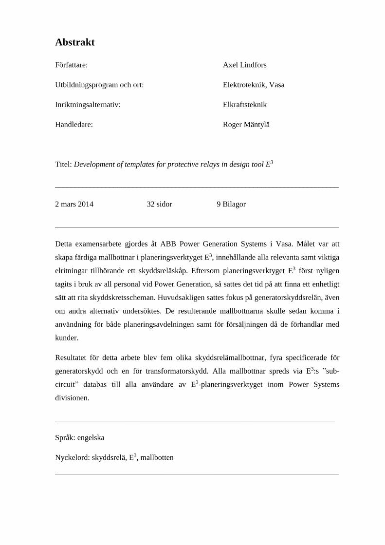
4.2.7 Layout
The layout schematic displays how different components and devices are placed in a
cubicle and how the cubicle itself is designed.
For these templates an ABB MNS type cubicle was used, with the cubicle description text
on the top left and top right side of the cubicle. The templates were designed with multiple
views of the cubicle, i.e. there was a front door view, back of front door view, front view
of the inside and a side view of the cubicle.
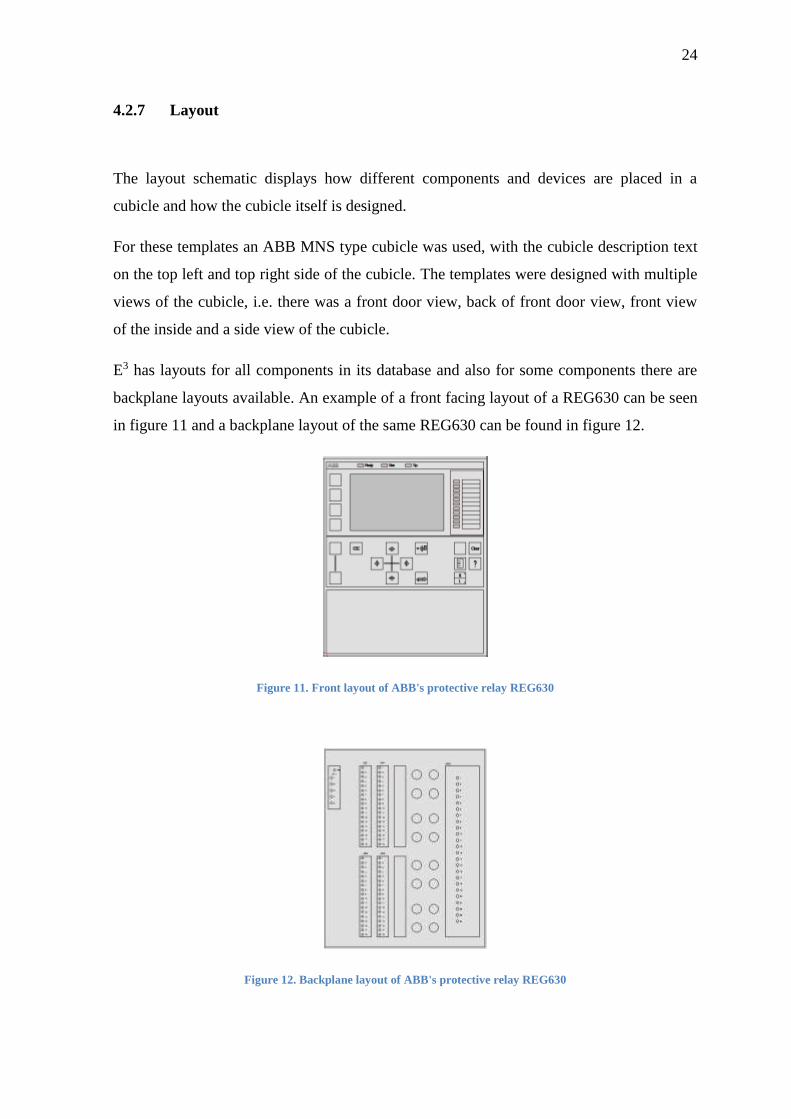
E3 has layouts for all components in its database and also for some components there are
backplane layouts available. An example of a front facing layout of a REG630 can be seen
in figure 11 and a backplane layout of the same REG630 can be found in figure 12.
Figure 11. Front layout of ABB's protective relay REG630
Figure 12. Backplane layout of ABB's protective relay REG630

25
The connection terminals in the layout schematic, and in the entire template, are designed
to be grouped together according to their device names, this to enable bridging of the
connection terminals and to isolate different circuits from one another, e.g. tripping circuits
from signal circuits. The inside of the cubicle is equipped with extra DIN-rails with future
expansion of protection devices and connection terminals in mind.
The layout schematic made for the REG670 template can be seen in appendix 8.
4.2.8 Reference tables
For IEDs in design tool E3 there is something called reference tables. These tables make
references to a component (often cards or modules) in the project and particularly to the
symbols used from that specific component. It shows i.e. the placement of a symbol used
from a device in the project.
Since the protective relays in this project had a lot of different input and output modules
(cards), this added a couple of sheets to the template. In figure 13 there is an example of
what a reference table of a power supply module from a REG670 looks like in E3.
Figure 13. Reference table of a Power Supply Module

26
4.2.9 Lists and tables
In E3 the generation of connection terminal tables, parts lists etc. is very easy once all the
connection terminals and devices are set up properly.
The connection terminals in this work were divided into categories depending on in which
segment they were in use. This meant that five different categories of connection terminals
were created. See the list down below.
- X1 (No. 100 and onwards) : AC Voltage
- X2 (No. 200 and onwards) : DC Voltage – auxiliary
- X3 (No. 300 and onwards) : AC Voltage – measurements
- X4 (No. 400 and onwards) : I/O – Signaling
- X5 (No. 500 and onwards) : Tripping circuits
There were two types of connection terminals used in this project. For signaling and supply
circuits Phoenix Contact terminals UT 2.5-MT-P/P were used and for the heavy duty
circuits (supply and measurements) connection terminals URTK/S-BEN6 by the same
manufacturer were used.
When generating the parts list of the template, it is important to make sure that all the
devices that are used are assigned to the right assembly (figure 14).

27
Figure 14. Description of assembly and device in design tool E3
An E3 terminal table showing the X1 connection terminals can be found in appendix 9.
4.3 Referencing of the inputs
The referencing system of signals in E3 enables the user to “jump” between schematics,
instead of opening a new drawing every time, e.g. when trying to cross reference two
separate drawings or follow a wire from one drawing to another.
In this template the invisible signal reference symbols (figure 15) and reference system
were used to facilitate the navigation between sheets, and ordinary signal referencing was
used for basic signal referencing. In the referencing system used for navigation, the
protection matrix contains the analogue and digital inputs as text and to make it easier for
the designer to jump to the actual symbols, a reference system was implemented.

28
Figure 15. Invisible signal reference symbols
To create this the invisible signal (figure 15) reference in E3 was utilized, but instead of
connecting a signal to it, it was only used as a link between the protection matrix and the
inputs. This creates a green signal reference text in the shape of XXX.YZ. The Xs tell the
sheet number, Ys the row and Zs the column of the linked signal reference. When moving
between the sheets in E3, the corresponding signal reference symbol gets surrounded by a
purple-coloured box to highlight it. The reference “jumping” also works when printing the
schematics into a PDF-format, although the highlighting function does not. A figure
describing the referencing system used in this project can be found in figure 16.
Figure 16. Operating principle of the referencing system in E3

29
5 Results
The main task of this Bachelor’s thesis was to create a standardized template for protective
relays in design tool E3. Special attention was paid to the single line diagram and
protection matrix, as so far there has been no single standard way of drawing these
schematics before.
The result of this work was five templates made of protection relays, four of which were
targeted for generator protection and one which was targeted for transformer protection.
These five templates were then included in ABB Power Systems’ E3 template library.
There were a lot of minor tasks involved in this work, and the biggest of them was to make
the measurement circuits as easy to interpret as possible. As seen in appendix 6, the
solution that in the end was adopted was that all the inputs relating to a card would be
displayed on a single sheet instead of being spread out on several different sheets.
The protection matrix was chosen to be designed as a table format, because it should be
easy to modify and easy to understand. The fact that the matrix should include everything
related to the protective relay made the choice easier, as there is a lot of information being
displayed in a protection matrix. The final version of an analogue signal protection matrix
can be found in appendix 3.
The main idea of the SLD was that they would be designed in such a way that the first
glimpse of the SLD would give the observer an extensive understanding of the system and
the protections implemented. The protection SLD for a REG670 generator protective relay
can be found in appendix 1. The corresponding SLD for a RET670 transformer protective
relay can be found in appendix 2.

30
6 Discussion
Before I started with this project I had been working as a summer trainee at the Power
Generation unit in Vaasa. During that period of time I came into contact with the E3 design
tool and understood what it was used for.
In the beginning of the work I had to study a lot of protective relay manuals and also try to
get used to working with E3 as it is a very broad design tool. I also acquainted myself also
with old AutoCAD drawings, trying to understand the way drawings had been made in this
unit before.
A lot of the time in the beginning was spent on the drawing of sample schematics, which
then were sent to be checked and approved. The first template took quite a while to be
finish. However, as the general idea was first to generate one template and by modifying
that generate the others, the rest of the templates became ready much faster.
The work with this project is over from my point of view and the templates made in this
work are now used by the marketing team and the design engineers in the Power
Generation unit. Although my work is done, there is most probably a need to develop more
templates as these are just the most common ones used in ABB’s projects.
I would imagine that in the future there could be a couple of changes made to the templates
if deemed necessary. One idea would be to extend the referencing system to the SLD, and
not only to the protection matrix. Creating universal templates for protection relays might
not be impossible, although it would require a lot of time setting up everything in E3.
During this work carried out for ABB Power Generation I have learned a lot about
protection relays, but also about the design tool E3 and the way of drawing schematics in
this unit of ABB. I have also gained a better understanding of the protection of electrical
power systems and in particular an in-depth understanding of the generator protection.

31
References
ABB (2013). Generator Protection REG670 IEC,
http://www.abb.com/product/db0003db004281/c12573e700330419c12572b4003c92c6.asp
x (read: 15.01.2014)
ABB (2007). REG670 – Generator Protection,
http://www.abb.de/cawp/seitp202/b2425a9262d50aadc12572bb002fb84a.aspx (read
14.01.2014)
ABB (2011). RXPE 41/40 – Directional overcurrent relay,
http://www05.abb.com/global/scot/scot313.nsf/veritydisplay/3c52f95ab99f01fbc12575230
034accd/$file/b03-3010e_en_rxpe_41_40_-90a_or_0a_directional_overcurrent_relay.pdf
(read 14.01.2014)
All About Circuits (2012). AC voltmeters and ammeters.
http://www.allaboutcircuits.com/vol_2/chpt_12/1.html (read: 15.01.2014).
Blackburn J.L. & Domin T.J. (2006). Protective Relaying: Principles and Applications,
Third Edition. Boca Raton: CRC Press.
CCS Group (2012). E3 series. http://www.ccsgroup.com (read 15.01.2014)
China Relay (2013). Electrical Network Protection – Current Relay, http://www.china-
relay.com/electrical-network-protection/electrical-network-protection-current-relay-
01.html (read 14.01.2014)

32
El-Hawary, M.E. (2000). Electrical Energy Systems. Boca Raton: CRC Press.
ELKRAFTSSYSTEM 1 (2012) Skydd av olika systemdelar, cha. 11 Stockholm: Liber AB
ISBN 978-91-47-05176-2.
Mörsky, J. (1993). Relesuojaustekniikka. Hämeenlinna: Otatieto.
Stien, M. (1986). Generatorskydd Applikationsguide AG03-4005.
Tpub.com (n.d.). Overlapping Protective Zones,
http://nuclearpowertraining.tpub.com/h1011v4/css/h1011v4_116.htm (read: 15.01.2014)
Ungrad, H. & Winkler, W. & Wiszniewski, A. (1995). Protection Techniques in Electrical
Energy Sytems. New York: Macel Dekker.
The ABB Group. www.abb.fi (read: 6.1.2014)
Zuken Inc. www.zuken.com/en (read: 1.2.2014)

APPENDIX 1

APPENDIX 2

APPENDIX 3

APPENDIX 4

APPENDIX 5

APPENDIX 6

APPENDIX 7

APPENDIX 8

APPENDIX 9