Embed Size (px)
Citation preview
DOI: 10.23883/IJRTER.2017.3352.ATUFP 220
Development of vocoder board for speech compression
at three different rates
Lavanya krishna1, Rajeswari P
2
1PG student, DSCE, Bangalore,
2Associate Professor, DSCE, Bangalore
Abstract: Compression of speech signal is an important field in digital signal processing. Because of
limited bandwidth in many fields especially in the field of military speech compression has a
significant importance in the present world. The other reasons for speech compression are limited
transmission and storage capacity. The process of converting human speech signals into encoded
representation then converting back into original signal by decoding back to produce a close
approximation of the original signal. This paper presents a speech compression by designing a low
bit rate Vocoder board. The process includes component selection for doing schematic followed by
PCB design. The final board is tested by giving speech input of different languages and then
calculating PESQ of both input and compressed speech.
Index Terms— Vocoder board, TWELP, Cool edit pro, PESQ, Software configuration.
I. INTRODUCTION1
According to information theory, the minimum bitrate at which the conditions of distortionless
transmission of any source signal is possible is determined by the entropy of the speech source
message. The compression after the maximum level compression results in distortion and loss of
signal. Various speech encoding techniques includes LPC, CELP, MELP and TWELP. Compression
of speech signal results in low bit rate data which reduces the bandwidth required for transmission.
Implementing better efficient compression techniques results in both quality and LBR data.
Encoding, decoding and compression of speech signal can be done using VOCODER . VOCODER
can be configured either by hardware or by software. In hardware configuration jumpers are used to
fix the voltage for configurable pins, where as in software configurations any of the processors or the
controllers can be used to configure the pins. The Blackfin device BF548 can be used to configure
and also to read and write the speech signals from and to the VOCODER respectively. On top of that
the read speech signal can be encrypted. The encryption of compressed speech signal is the main
requirement.
A large part of the researches in speech process algorithms is motivated by the need of obtaining
secure military communications, to allow effective operation in a hostile environment. Since the
bandwidth of the communication channel is a sensitive problem in military applications, low bit-rate
speech compression methods are used. Several speech processing applications such as Mixed
Excitation Linear Prediction are characterized by very strict requirements in power consumption,
size, and voltage supply. These requirements are difficult to fulfill, given the complexity and number
of functions to be implemented, together with the real time requirement and large dynamic range of
the input signals. To meet these constraints, careful optimization should be done at all levels, ranging
from algorithmic level, through system and circuit architecture, to layout and design of the cell
library. The key points of this optimization are among others, the choice of the algorithms, the
International Journal of Recent Trends in Engineering & Research (IJRTER)
Volume 03, Issue 07; July - 2017 [ISSN: 2455-1457]
@IJRTER-2017, All Rights Reserved 221
modification of the algorithms to reduce computational complexity, the choice of a fixed-point
arithmetic unit, the minimization of the number of bits required at every node of the algorithm, and a
careful match between algorithms and architecture. This paper concentrates on low bit rate speech
coding technology, mainly in TWELP and solved the problem of optimizing the program of TWELP
on Digital Signal Processor platform. The algorithm was ported onto a fixed point DSP, Blackfin
537, and stage by stage optimization was performed to meet the real time requirements. The main
functions involved were analysis, parameter encoding, parameter decoding and synthesis. The fixed
point source code at the TWELP front end was also thoroughly optimized at the C Level. Memory
optimization techniques such as data placement and caching were also used to reduce the processing
time. The results were obtained show that real-time implementations of a speech Vocoder based on
the TWELP standard for low bit rate communications (2400 bps) can be successful on DSP
platforms.
1. STATEMENT OF THE PROBLEM
As already discussed in introduction bandwidth in any communication system plays a critical role.
Efficient use of bandwidth is of main concern in any kind of communication. When the data to be
transmitted is compressed then the bandwidth requirement for compressed data transmission will
also decreases. Not only the bandwidth requirement but also the capacities to store the data will also
decreases which in turn decrease the time to access the data. Some of the existing compression
technique may result in low bit rate data but may fail to produce better quality speech. In order to
achieve the above conditions compression of data which results in speech with better quality and also
of low bit rate has to be used. These requirement leads to the development of a compression
technique which results in speech with better quality and also of low bit rate.
II. MOTIVATION
In any field of communication the bandwidth is the most important requirement. In order to reduce
the bandwidth requirement in any communication system especially in the field of military speech
compression is one of the prominent methods among many other techniques to reduce the need of
bandwidth. The disadvantages like bad speech quality, less compression ratio and so on leads to this
method of speech compression using low bitrate vocoder.
III. OBJECTIVE
The main objective of this project is to reduce the bandwidth requirement in communication system
by performing a speech compression especially in military applications. Other than reduction of
bandwidth the project also aimed at keeping the speech quality as good as the input speech even after
performing compression. The compression of speech of different languages, maintaining the PESQ
of the output speech signal is also the aim of this project.
Performing the compression of different speech signal with different rates is one of the objectives of
this project. The compression of 21 different languages at three different rates such as 600bps,
1200bps and 600bps is also in the list of objectives of this project.
IV. METHODOLOGY
The speech to be compressed is given as an input to the low bit rate vocoder board where in the
speech signal is encoded and compressed by vocoder chip and the encoded and compressed speech
will be decoded and decompressed at the receiver side. The decompressed speech can be playback to
hear the speech. The output speech is tested for its quality by checking its PESQ. The PESQ of
output speech is compared with that of input speech. There are many methods to do the compression;
International Journal of Recent Trends in Engineering & Research (IJRTER)
Volume 03, Issue 07; July - 2017 [ISSN: 2455-1457]
@IJRTER-2017, All Rights Reserved 222
in this project vocoder is implemented as a speech compressor. The compression algorithm used here
is the TWELP.
1.1 VOCODER
The Vocoder is a chip of 128 pins. It has built-in FLASH and RAM and can perform real time speech
compression. The main advantage is that there will be no need for external storage which decreases
the complexity. It supports three different rates such as 600bps, 1200bps and 2400bps which are
configurable either by software or by hardware.
Vocoder chip can integrate the codec AD73311 or AIC23 seamlessly and configure it when powering
up without user involving. The board with Vocoder chip is connected to BF548 via UART. The
communication between board and BF548 unit is Asynchronous and Full duplex. There are three
ports available in BF548, among them port 3 is used for the purpose of trans reception between
vocoder board and BF548.
The board supports four different baud rates, three different coding rate, MICIN mode, LINEIN
mode, two different CODEC such as AIC23 and AD73311 which can be configurable either by
software or by hardware.
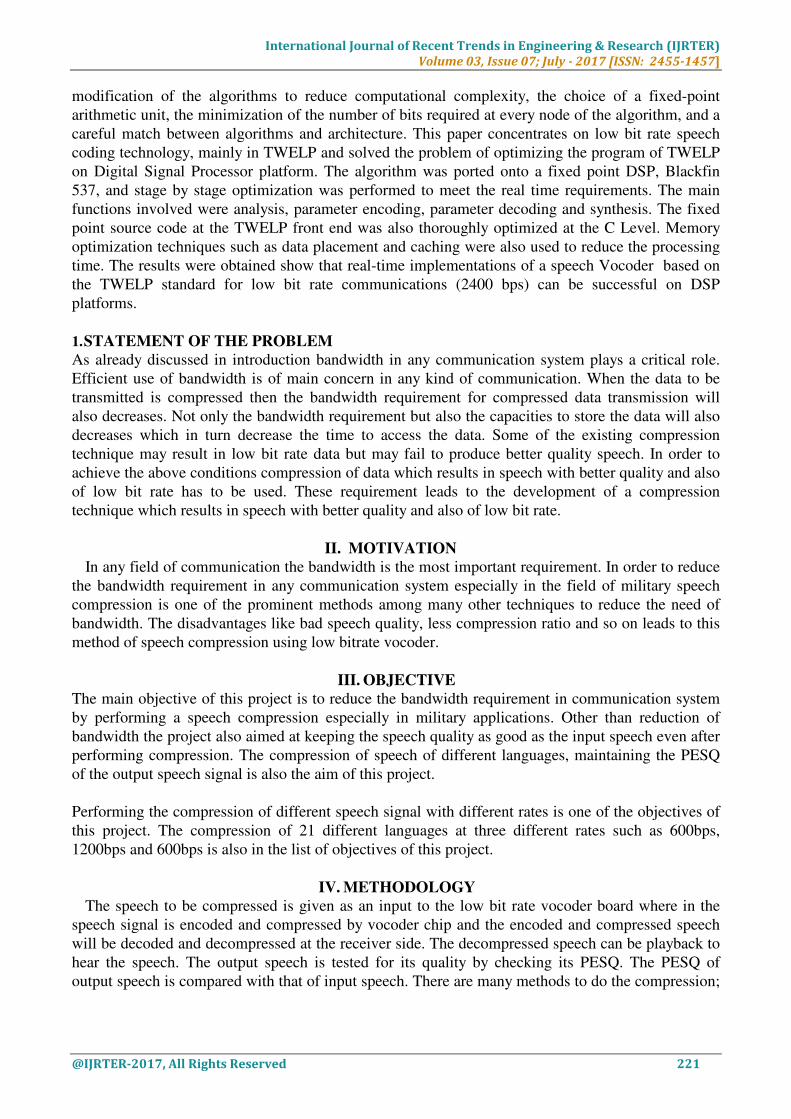
5.2 BF548
The architecture of BF548 is described in this section
Figure 1: BF548 architecture
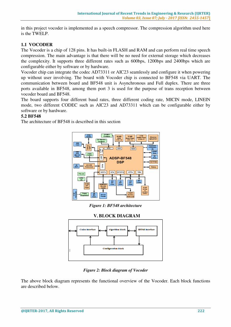
V. BLOCK DIAGRAM
Figure 2: Block diagram of Vocoder
The above block diagram represents the functional overview of the Vocoder. Each block functions
are described below.
International Journal of Recent Trends in Engineering & Research (IJRTER)
Volume 03, Issue 07; July - 2017 [ISSN: 2455-1457]
@IJRTER-2017, All Rights Reserved 223
6.1 Algorithm block
The function of algorithm block is to implement the functions related to encoding/decoding
algorithm. This block is the core module of Vocoder chip.
During encoding the algorithm block receive speech data from the codec interface block then
compress and encode the data and then send to the BF548 interface clock to transmit.
During decoding the algorithm block receive data from the BF548 block, decodes the data and then
send to the codec interface module to playback.
6.2 CODEC interface block
The codec interface block connects to the external codec to which the speech data to be
compressed has to be send.
During encoding the codec interface block receives the speech data from external codec and then
sends it to an algorithm block to do compression encoding.
During decoding the codec interface block receives the decoded speech data from algorithm block
and then send it back to the external codec to play.
6.3 BF548 interface block
The BF548 block connects to the external BF548 and is used to transport encoded/decoded data
and also the configuration data.
During encoding the BF548 block receives data from algorithm block frame them and send to
external BF548 unit.
During decoding, the BF548 interface block receives speech data frame from external BF548 unit
decode the frames and then send to algorithm block for speech data encoding.
During configuring BF548 interface block receives configuring data frame from external BF548,
decode the frames and then send to the configuration block for parsing and configuring.
The communication between BF548 and configuration block is full duplex therefore the
configuration data, encoded data and decoded data can be send simultaneously.
6.4 Configuration block
This block configure the chip function according to configure pin status or external configure data.
When powered up, configure block samples the configure pins’ status to configure the chip
accordingly.
When in operating, the configure block accepts the data from BF548 interface block BF548 and
configure related blocks after parsing the data.
VI. BOARD COMPOSITION
This section describes the components of developed board. Figure 3.2 is the developed board. Figure
3.3 represents the detailed representation of the developed board which named every components in
the board.
International Journal of Recent Trends in Engineering & Research (IJRTER)
Volume 03, Issue 07; July - 2017 [ISSN: 2455-1457]
@IJRTER-2017, All Rights Reserved 224
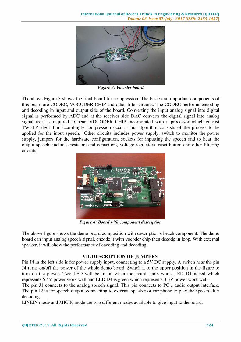
Figure 3: Vocoder board
The above Figure 3 shows the final board for compression. The basic and important components of
this board are CODEC, VOCODER CHIP and other filter circuits. The CODEC performs encoding
and decoding in input and output side of the board. Converting the input analog signal into digital
signal is performed by ADC and at the receiver side DAC converts the digital signal into analog
signal as it is required to hear. VOCODER CHIP incorporated with a processor which consist
TWELP algorithm accordingly compression occur. This algorithm consists of the process to be
applied for the input speech. Other circuits includes power supply, switch to monitor the power
supply, jumpers for the hardware configuration, sockets for inputting the speech and to hear the
output speech, includes resistors and capacitors, voltage regulators, reset button and other filtering
circuits.
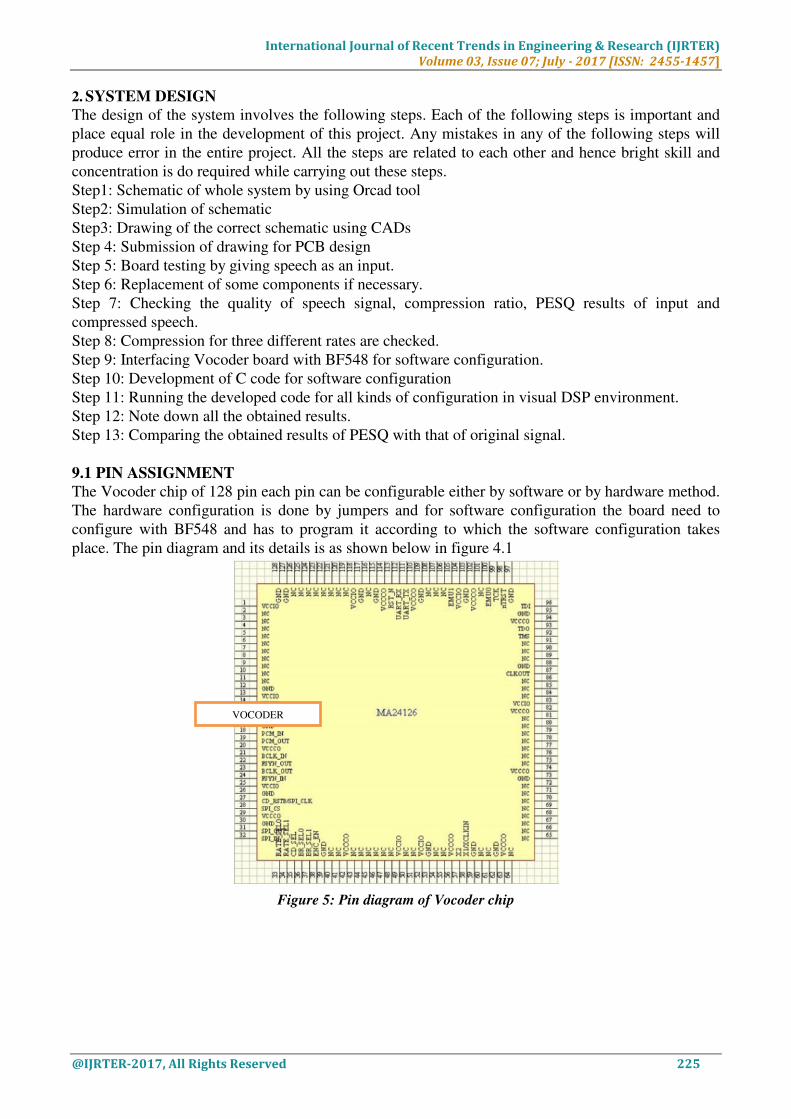
Figure 4: Board with component description
The above figure shows the demo board composition with description of each component. The demo
board can input analog speech signal, encode it with vocoder chip then decode in loop. With external
speaker, it will show the performance of encoding and decoding.
VII. DESCRIPTION OF JUMPERS
Pin J4 in the left side is for power supply input, connecting to a 5V DC supply. A switch near the pin
J4 turns on/off the power of the whole demo board. Switch it to the upper position in the figure to
turn on the power. Two LED will be lit on when the board starts work. LED D1 is red which
represents 5.5V power work well and LED D4 is green which represents 3.3V power work well.
The pin J1 connects to the analog speech signal. This pin connects to PC’s audio output interface.
The pin J2 is for speech output, connecting to external speaker or ear phone to play the speech after
decoding.
LINEIN mode and MICIN mode are two different modes available to give input to the board.
International Journal of Recent Trends in Engineering & Research (IJRTER)
Volume 03, Issue 07; July - 2017 [ISSN: 2455-1457]
@IJRTER-2017, All Rights Reserved 225
2. SYSTEM DESIGN
The design of the system involves the following steps. Each of the following steps is important and
place equal role in the development of this project. Any mistakes in any of the following steps will
produce error in the entire project. All the steps are related to each other and hence bright skill and
concentration is do required while carrying out these steps.
Step1: Schematic of whole system by using Orcad tool
Step2: Simulation of schematic
Step3: Drawing of the correct schematic using CADs
Step 4: Submission of drawing for PCB design
Step 5: Board testing by giving speech as an input.
Step 6: Replacement of some components if necessary.
Step 7: Checking the quality of speech signal, compression ratio, PESQ results of input and
compressed speech.
Step 8: Compression for three different rates are checked.
Step 9: Interfacing Vocoder board with BF548 for software configuration.
Step 10: Development of C code for software configuration
Step 11: Running the developed code for all kinds of configuration in visual DSP environment.
Step 12: Note down all the obtained results.
Step 13: Comparing the obtained results of PESQ with that of original signal.
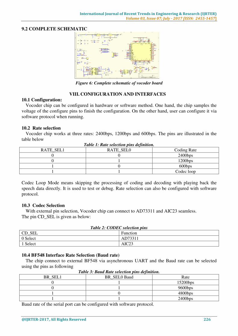
9.1 PIN ASSIGNMENT
The Vocoder chip of 128 pin each pin can be configurable either by software or by hardware method.
The hardware configuration is done by jumpers and for software configuration the board need to
configure with BF548 and has to program it according to which the software configuration takes
place. The pin diagram and its details is as shown below in figure 4.1
Figure 5: Pin diagram of Vocoder chip
VOCODER
International Journal of Recent Trends in Engineering & Research (IJRTER)
Volume 03, Issue 07; July - 2017 [ISSN: 2455-1457]
@IJRTER-2017, All Rights Reserved 226
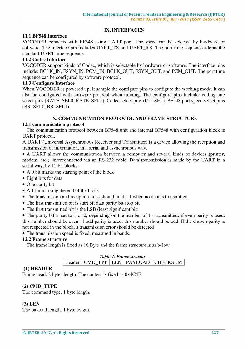
9.2 COMPLETE SCHEMATIC
Figure 6: Complete schematic of vocoder board
VIII. CONFIGURATION AND INTERFACES
10.1 Configuration:
Vocoder chip can be configured in hardware or software method. One hand, the chip samples the
voltage of the configure pins to finish the configuration. On the other hand, user can configure it via
software protocol when running.
10.2 Rate selection
Vocoder chip works at three rates: 2400bps, 1200bps and 600bps. The pins are illustrated in the
table below Table 1: Rate selection pins definition.
RATE_SEL1 RATE_SEL0 Coding Rate
0 0 2400bps
0 1 1200bps
1 0 600bps
1 1 Codec loop
Codec Loop Mode means skipping the processing of coding and decoding with playing back the
speech data directly. It is used to test or debug. Rate selection can also be configured with software
protocol.
10.3 Codec Selection
With external pin selection, Vocoder chip can connect to AD73311 and AIC23 seamless.
The pin CD_SEL is given as below:
Table 2: CODEC selection pins
CD_SEL Function
0 Select AD73311
1 Select AIC23
10.4 BF548 Interface Rate Selection (Baud rate)
The chip connect to external BF548 via asynchronous UART and the Baud rate can be selected
using the pins as following Table 3: Baud Rate selection pins definition.
BR_SEL1 BR_SEL0 Baud Rate
0 1 15200bps
0 1 9600bps
1 0 4800bps
1 1 2400bps
Baud rate of the serial port can be configured with software protocol.
International Journal of Recent Trends in Engineering & Research (IJRTER)
Volume 03, Issue 07; July - 2017 [ISSN: 2455-1457]
@IJRTER-2017, All Rights Reserved 227
IX. INTERFACES
11.1 BF548 Interface
VOCODER connects with BF548 using UART port. The speed can be selected by hardware or
software. The interface pin includes UART_TX and UART_RX. The port time sequence adopts the
standard UART time sequence.
11.2 Codec Interface
VOCODER support kinds of Codec, which is selectable by hardware or software. The interface pins
include: BCLK_IN, FSYN_IN, PCM_IN, BCLK_OUT, FSYN_OUT, and PCM_OUT. The port time
sequence can be configured by software protocol.
11.3 Configure Interface
When VOCODER is powered up, it sample the configure pins to configure the working mode. It can
also be configured with software protocol when running. The configure pins include: coding rate
select pins (RATE_SEL0, RATE_SEL1), Codec select pins (CD_SEL), BF548 port speed select pins
(BR_SEL0, BR_SEL1).
X. COMMUNICATION PROTOCOL AND FRAME STRUCTURE
12.1 communication protocol
The communication protocol between BF548 unit and internal BF548 with configuration block is
UART protocol.
A UART (Universal Asynchronous Receiver and Transmitter) is a device allowing the reception and
transmission of information, in a serial and asynchronous way.
• A UART allows the communication between a computer and several kinds of devices (printer,
modem, etc.), interconnected via an RS-232 cable. Data transmission is made by the UART in a
serial way, by 11-bit blocks:
• A 0 bit marks the starting point of the block
• Eight bits for data
• One parity bit
• A 1 bit marking the end of the block
• The transmission and reception lines should hold a 1 when no data is transmitted.
• The first transmitted bit is start bit data parity bit stop bit
• The first transmitted bit is the LSB (least significant bit)
• The parity bit is set to 1 or 0, depending on the number of 1's transmitted: if even parity is used,
this number should be even; if odd parity is used, this number should be odd. If the chosen parity is
not respected in the block, a transmission error should be detected
• The transmission speed is fixed, measured in bauds.
12.2 Frame structure
The frame length is fixed as 16 Byte and the frame structure is as below:
Table 4: Frame structure
Header CMD_TYP LEN PAYLOAD CHECKSUM
(1) HEADER
Frame head, 2 bytes length. The content is fixed as 0x4C4E
(2) CMD_TYPE
The command type, 1 byte length.
(3) LEN
The payload length. 1 byte length.
International Journal of Recent Trends in Engineering & Research (IJRTER)
Volume 03, Issue 07; July - 2017 [ISSN: 2455-1457]
@IJRTER-2017, All Rights Reserved 228
(4) PAYLOAD
The payload data. 11 bytes length.
(5) CHECKSUM
Checksum is a 1 byte length. Add the first 15 bytes in a frame (it means the total frame
excluding checksum itself) and get the low 8 bits of the sum as the checksum.
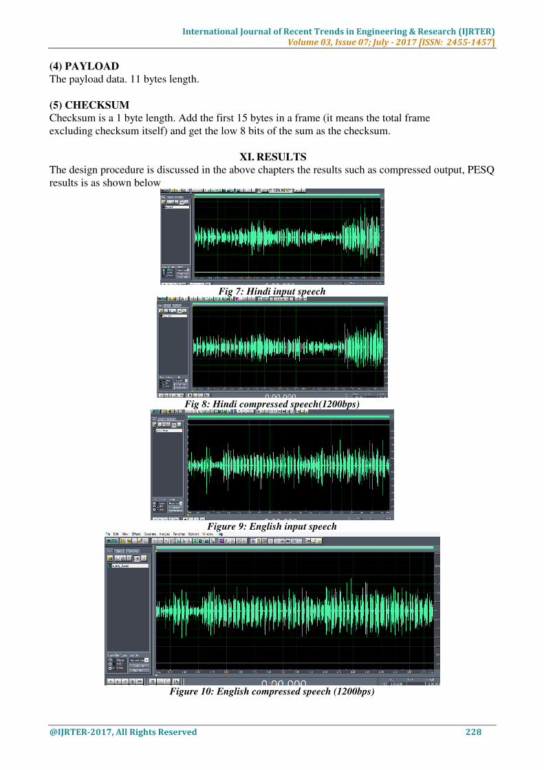
XI. RESULTS
The design procedure is discussed in the above chapters the results such as compressed output, PESQ
results is as shown below
Fig 7: Hindi input speech
Fig 8: Hindi compressed speech(1200bps)
Figure 9: English input speech
Figure 10: English compressed speech (1200bps)
International Journal of Recent Trends in Engineering & Research (IJRTER)
Volume 03, Issue 07; July - 2017 [ISSN: 2455-1457]
@IJRTER-2017, All Rights Reserved 229
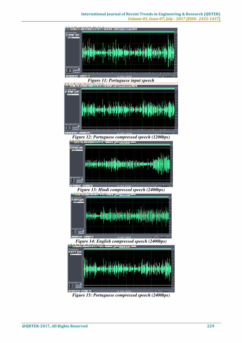
Figure 11: Portuguese input speech
Figure 12: Portuguese compressed speech (1200bps)
Figure 13: Hindi compressed speech (2400bps)
Figure 14: English compressed speech (2400bps)
Figure 15: Portuguese compressed speech (2400bps)
International Journal of Recent Trends in Engineering & Research (IJRTER)
Volume 03, Issue 07; July - 2017 [ISSN: 2455-1457]
@IJRTER-2017, All Rights Reserved 230
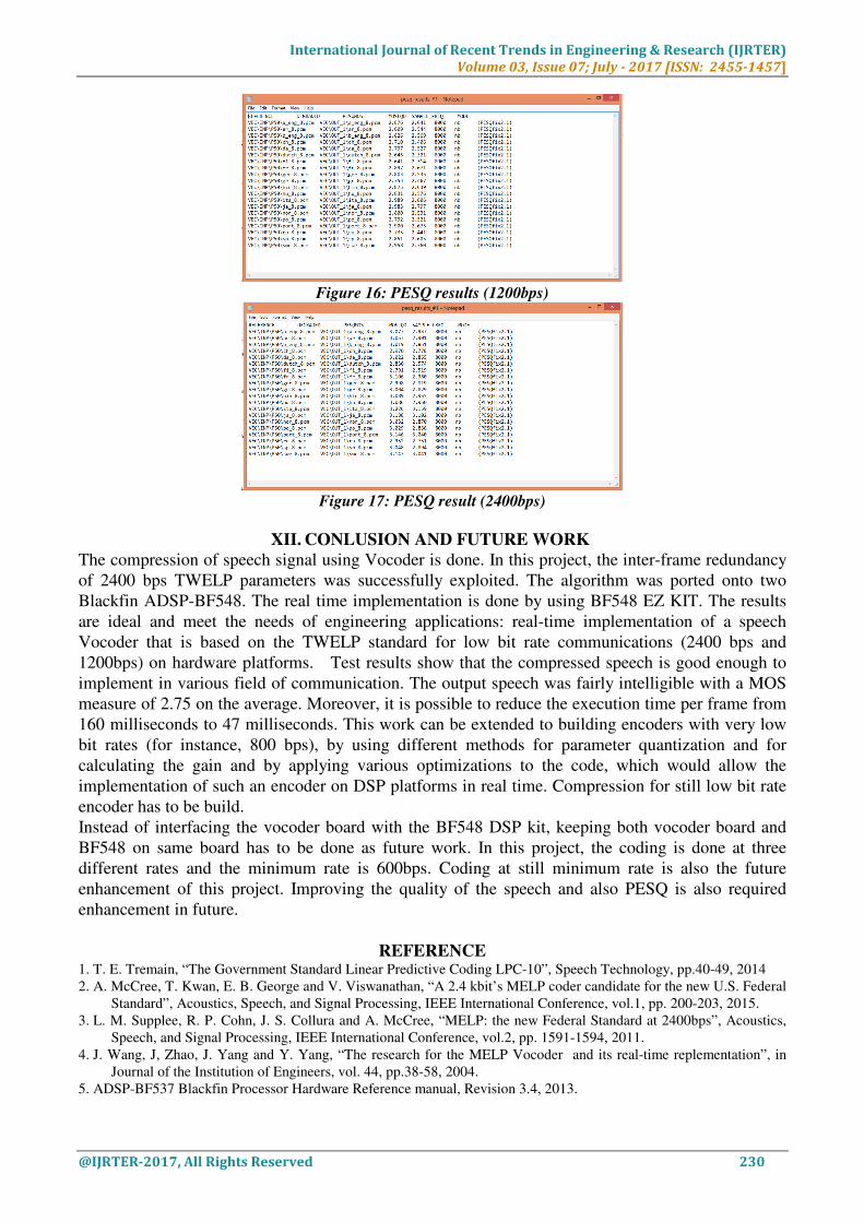
Figure 16: PESQ results (1200bps)
Figure 17: PESQ result (2400bps)
XII. CONLUSION AND FUTURE WORK
The compression of speech signal using Vocoder is done. In this project, the inter-frame redundancy
of 2400 bps TWELP parameters was successfully exploited. The algorithm was ported onto two
Blackfin ADSP-BF548. The real time implementation is done by using BF548 EZ KIT. The results
are ideal and meet the needs of engineering applications: real-time implementation of a speech
Vocoder that is based on the TWELP standard for low bit rate communications (2400 bps and
1200bps) on hardware platforms. Test results show that the compressed speech is good enough to
implement in various field of communication. The output speech was fairly intelligible with a MOS
measure of 2.75 on the average. Moreover, it is possible to reduce the execution time per frame from
160 milliseconds to 47 milliseconds. This work can be extended to building encoders with very low
bit rates (for instance, 800 bps), by using different methods for parameter quantization and for
calculating the gain and by applying various optimizations to the code, which would allow the
implementation of such an encoder on DSP platforms in real time. Compression for still low bit rate
encoder has to be build.
Instead of interfacing the vocoder board with the BF548 DSP kit, keeping both vocoder board and
BF548 on same board has to be done as future work. In this project, the coding is done at three
different rates and the minimum rate is 600bps. Coding at still minimum rate is also the future
enhancement of this project. Improving the quality of the speech and also PESQ is also required
enhancement in future.
REFERENCE 1. T. E. Tremain, “The Government Standard Linear Predictive Coding LPC-10”, Speech Technology, pp.40-49, 2014
2. A. McCree, T. Kwan, E. B. George and V. Viswanathan, “A 2.4 kbit’s MELP coder candidate for the new U.S. Federal
Standard”, Acoustics, Speech, and Signal Processing, IEEE International Conference, vol.1, pp. 200-203, 2015.
3. L. M. Supplee, R. P. Cohn, J. S. Collura and A. McCree, “MELP: the new Federal Standard at 2400bps”, Acoustics,
Speech, and Signal Processing, IEEE International Conference, vol.2, pp. 1591-1594, 2011.
4. J. Wang, J, Zhao, J. Yang and Y. Yang, “The research for the MELP Vocoder and its real-time replementation”, in
Journal of the Institution of Engineers, vol. 44, pp.38-58, 2004.
5. ADSP-BF537 Blackfin Processor Hardware Reference manual, Revision 3.4, 2013.
International Journal of Recent Trends in Engineering & Research (IJRTER)
Volume 03, Issue 07; July - 2017 [ISSN: 2455-1457]
@IJRTER-2017, All Rights Reserved 231
6. M. Olausson and L. Dake, “The ADSP-21535 Blackfin and Speech Coding”, Proceedings of the Swedish System-on-
chip Conference (SSoCC), 2003.
7. Blackfin DSP Instruction Set Reference, 2002.
8. ADSP-21535 Blackfin DSP Hardware Reference, 2002.
9. ITU-t recommendation on g.723.1, dual rate speech coder for multimedia communications transmitting at 5.3 and 6.3
kbit/s, 2013
10. ITU-t recommendation g.729, coding of speech at 8 kbit/s using conjugate-structure algebraic-codeexcited-linear-
prediction (cs-acelp), 2014
11. ETSI GSM Fullrate Speech Codec for Analog Devices Blackfin, Bayer DSP Solutions, 2008.
12. G. Bertini, F. Fontata, D. Gonzalez, L. Grassi and M. Magrini, “Voice Transformation Algorithms with Real Time
DSP Rapid Prototyping Tools”, 2004, unpublished.
13. Y. Shaked and A. L. Cole, “Implementation of MELP based Vocoder for 1200/2400 bps”, The EE Project Contest
2000, Technion Signal and Image Processing Lab, 2000, unpublished.
14. J. M. Valin , “Speex: A Free Codec for Free Speech”, available at http://jmvalin.ca/papers/speex_lca2006.pdf (Last
Accessed: May 2015).
15. Vorbis codec, available at http://www.vorbis.com/ (Last Accessed: May 2015).
16. ITU-T Recommendation P.800 Methods for subjective determination of transmission quality, available at
http://www.itu.int/ITU-T/ recommendations/rec.aspx?rec=3638 (Last Accessed: May 2015).
17. J. M. Gibson, “Speech coding methods, standards, and applications”, in Circuits and Systems Magazine, IEEE, vol.
5, pp. 30-49, 2005.