Embed Size (px)
Citation preview
I,. AdQ
SV0 '
DESIGN HANDBOOKUMBILICAL LOCKING MECHANISMDEVELOPMENT PROGRAM
CPtRYSLER COR!ORATION
Huntsville, Ala.
Jbr George C, Marsha/ISpace Fight Ceunhl
NATIONAL AERONAUTICS AND SPACE ADMINISTRATION WASHINGTON, D. C. MAY 1968
, • ",, • II••I ' ,!Ir ,• - " + •i+t"• 1 "-•" • "++•l'ivlwm PF'II •• I
NASA CR- 1021
DESIGN HANDBOOK
UMBILICAL LOCKING MECHANISM
DEVELOPMENT PROGRAM
By David L. Cusick
Distribution of this report is provided in the interest ofinformation exchange. Responsibility for the contentsresides in the author or organization that prepared it.
Prepared under Contract No. NAS 8-20649 byCHRYSLER CORPORATION
Huntsville, Ala.
for George C. Marshall Space Flight Center
NATIONAL AERONAUTICS AND SPACE ADMINISTRATION
For sale by the Clearinghouse for Federal Scientific and Technical InformationSpringfield, Virginia 22151 - CFSTI price $3.00
DESIGN HANDBOOK
LOCKING MECHANISMS
By
David L. Cusick
Electrical Systems and GSE Engineering DepartmentChrysler Corporation Space Division
Huntsville, Alabama
ABSTRACT
This handbook presents the techniques, developed in an intensive testingprogram, for use in designing ball-lock mechanisms for use on space vehicleumbilicals. In addition to the general design of this locking device and itscomponent parts, this handbook covers the effects of component surface conditioning,temperatures from ambient to minus 196 degrees Centigrade (°C), materials andmaterial hardness, and forces on the locking device up to 5000 pounds.
For the convenience of the reader, the final test report under thiscontract is included as an addendum to this report.
ifi
DESIGN HANDBOOK
LOCKING MECHANISMS
SUMMARY
The information presented in this handbook is the product of a test programconducted by Chrysler Corporation Space Division, Huntsville Operations underContract Number NAS8-20649.
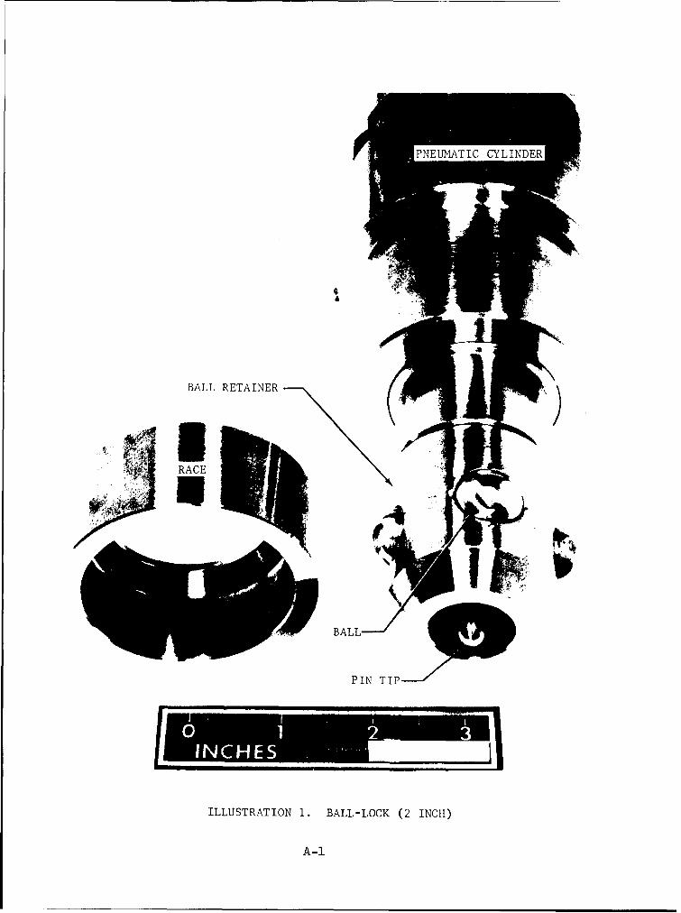
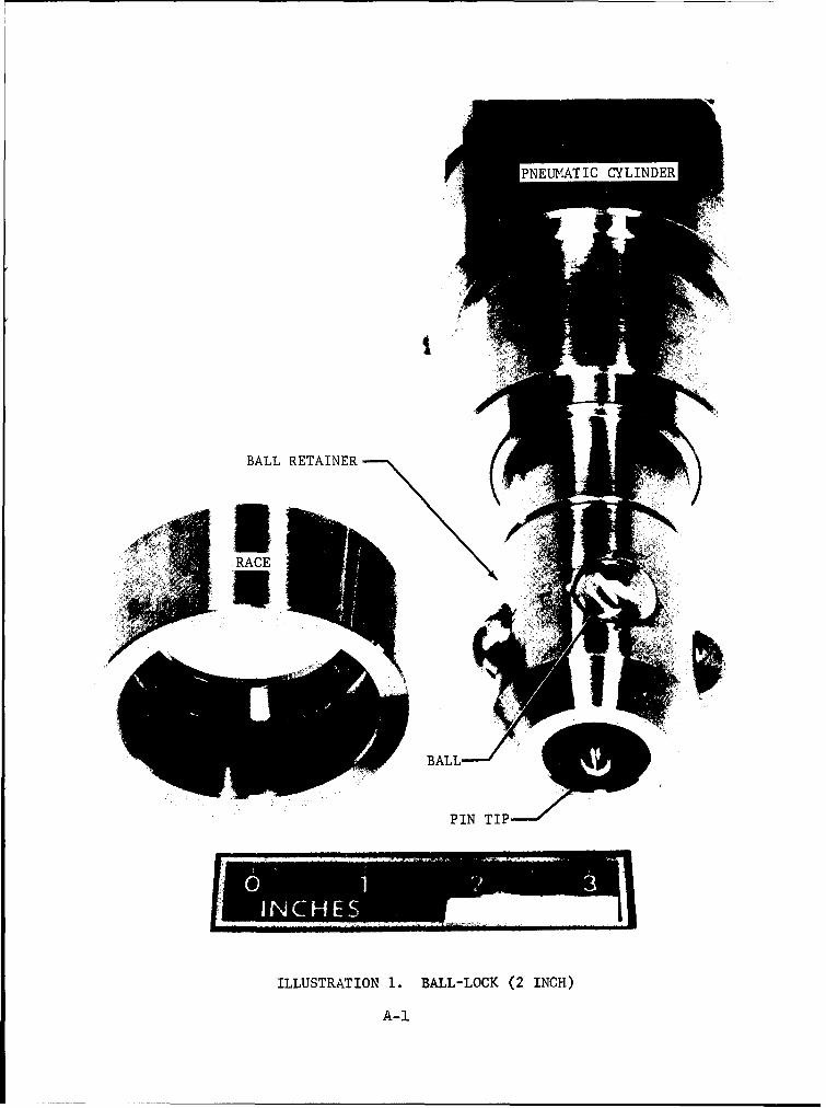
TFhe locking devices investigated in this program were limited to two types,ball-locks and collet-locks. The ball-lock mechani s(illustration 1, Appendix A)
E-onsists of two basic parts, a vehicle half or ball race and a ground half thatperforms the mechanics of locking or unlocking. The ground half of the ball-locking mechanism houses the balls and the release pin that is mechanically orpneumatically actuated to accomplish the locking or unlocking function.
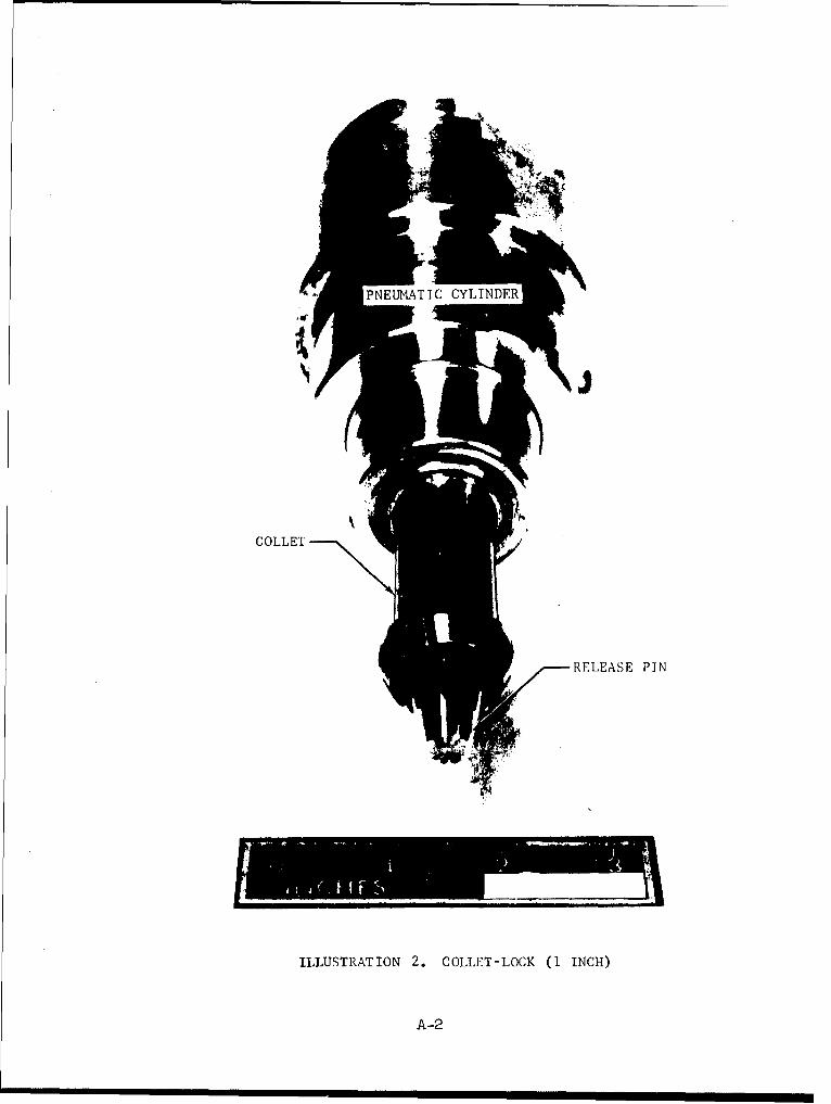
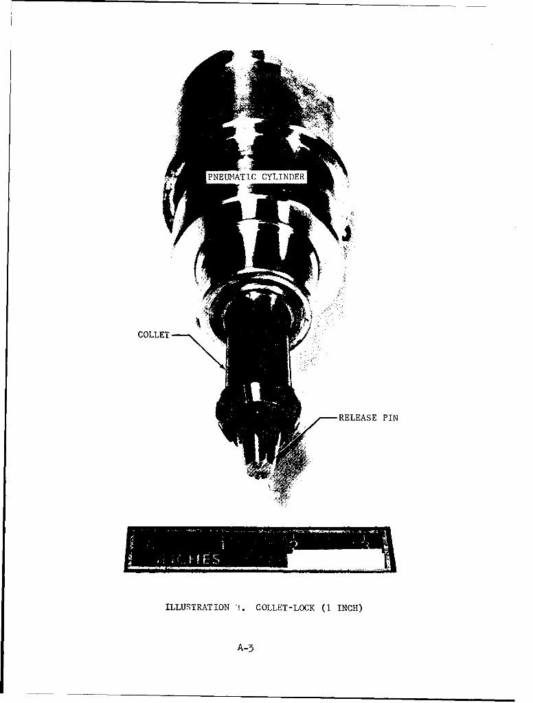
The collet-lock mechanismj (Illustration 2)finv~estigated in this testprogram, like the ball-lock, consists of a vehicle half or seat and a groundhalf that performs the mechanics of locking or unlocking. The ground half ofthe collet-lock mechanism is a one-piece, segmented, cantilever configuration
fabricated from a spring material such as beryllium copper. The release pin inthe collet-lock mechanism may also be mechanically or pneumatically actuated.
The testing program indicated that the ball-lock mechanism is to be greatlypreferred over the collet-lock mechanism. The degree of effort involved in thedesign of collet-lock mechanisms is too involved and too time consuming for theend result. The ball-Jock mechanism will more than adequately perform the lockingfunction and is more easily designed and manufactured. For these reasons thishandbook is limited to the design of ball-lock mechanisms onlyj _ p. 7
SECTION I. INTRODUCTION
This handbook covers the design of ball-lock mechanisms for use on spacevehicle umbilicals. The design information presented in this handbook is theproduct of a test program conducted by the Electrical Systems and GSE EngineeringDepartment, Chrysler Corporation Space Division, Huntsville Operations.
In addition to the general design of this locking mechanism and its components,the effects of component surface conditioning, temperatures from ambient to minus196oC, materials and material hardnesses, and forces (pre-loads*) on the lockingdevice up to 5000 pouids are presented.
This information was compiled to aid in the future design of umbilicallocking mechanisms. The use of this information will increase hardware reliabilityand life and by standardizing umbilical lock designs will increase the inter-changeability of parts among umbilical locks of different vehicles and vehiclestages.
This handbook is limited to the design of the components of the ball-lockthat actually perform the locking function and does not include the pneumaticcylinder or mechanical system that supplies the force for lock release.
* For the purpose of this handbook pre-loads refer to those forces that areapplied to the locking mechanism to maintain contact between both halvesof the umbilical and those forces on the locking mechanism that result fromvibration, umbilical weight, wind effects, vehicle sway, etc.)
2
SECTION II. DESCRIPTION
CONFIGURATION
A. ENVELOI'E
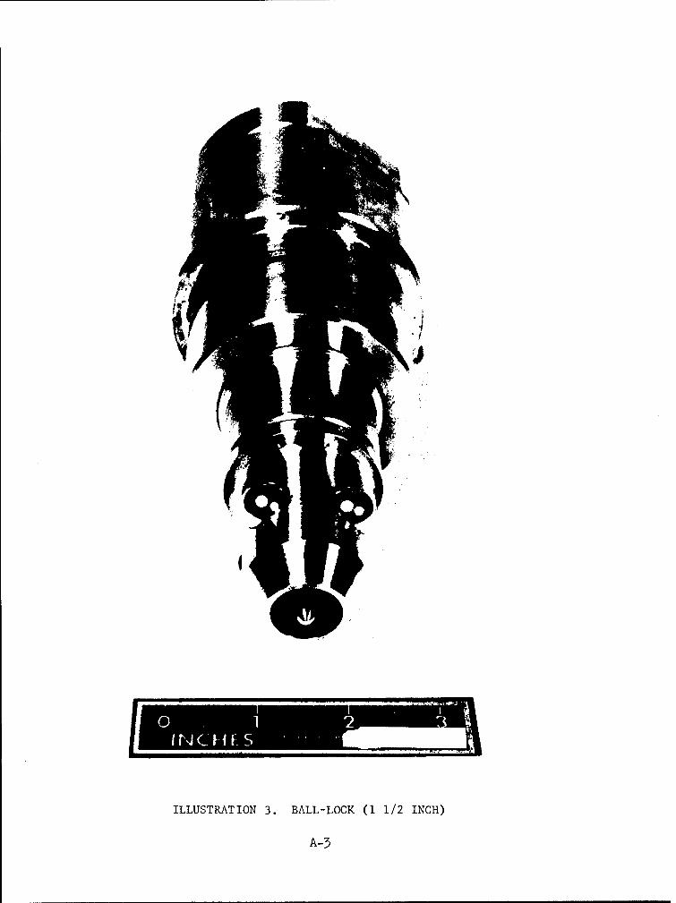
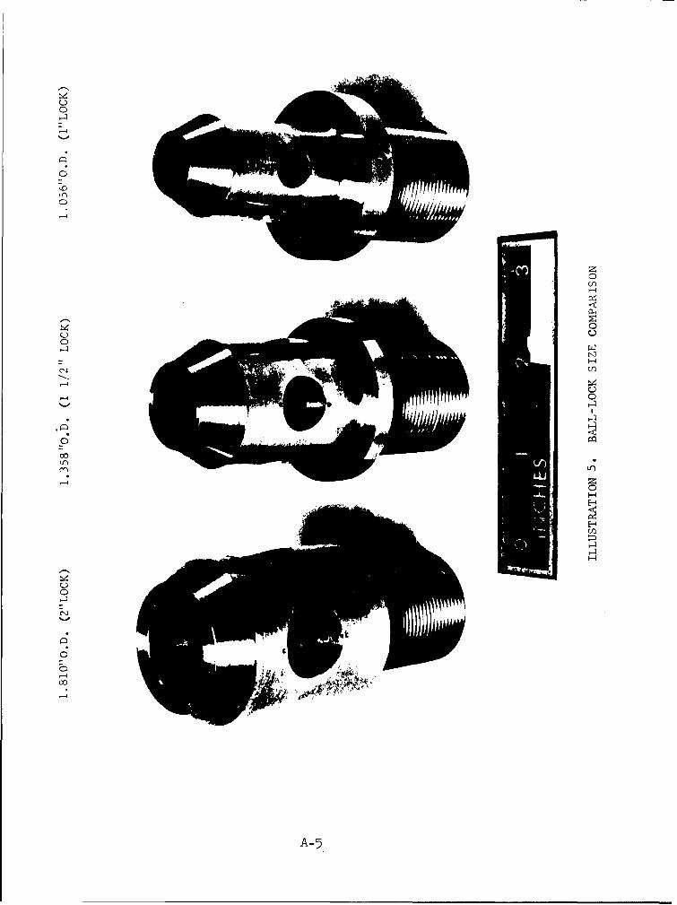
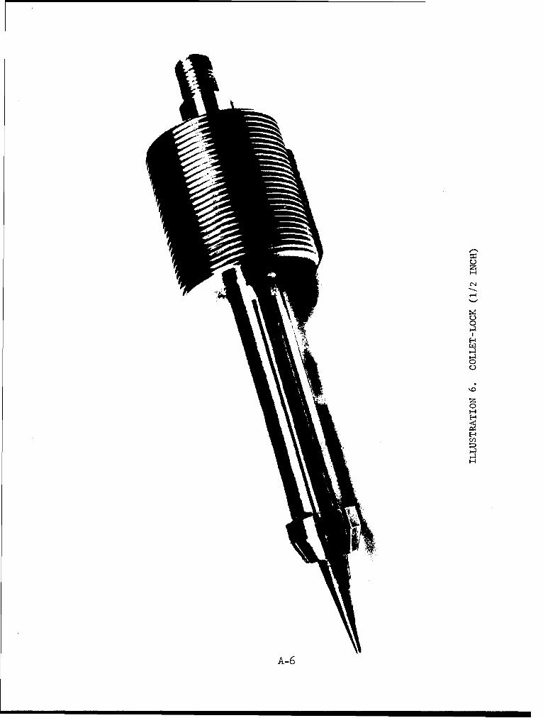
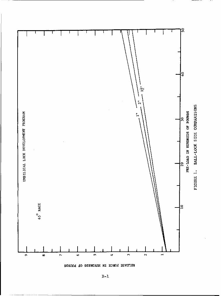
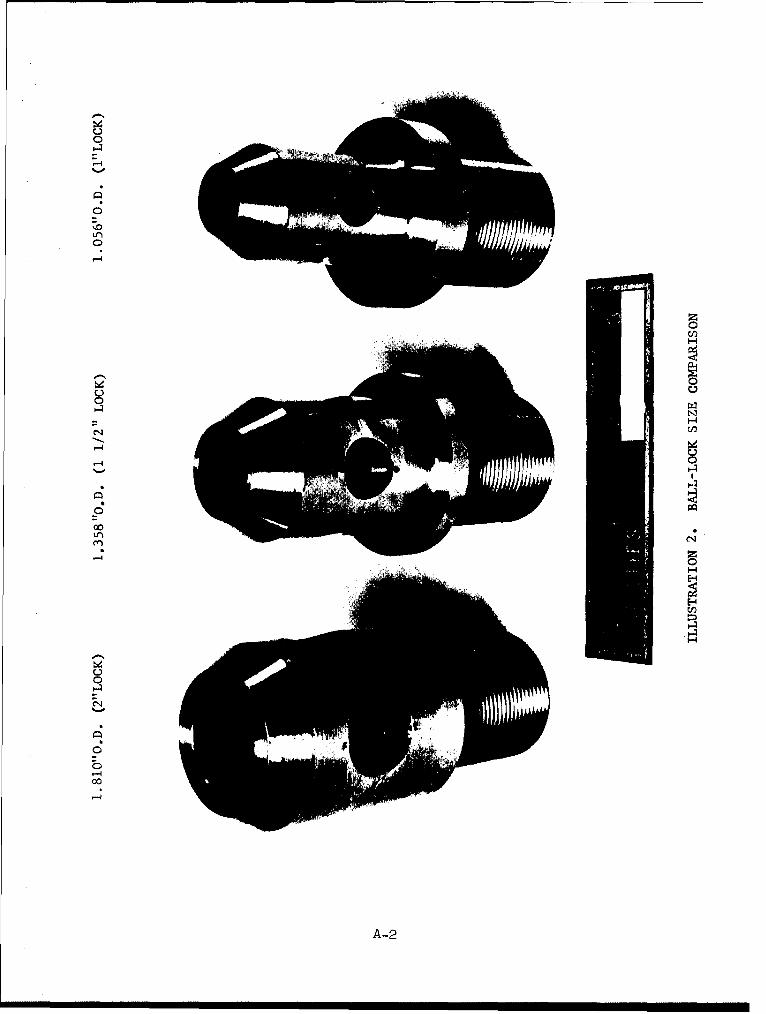
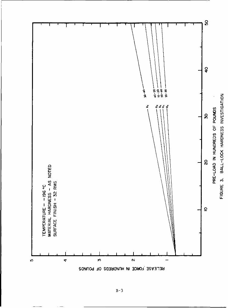
The first consideration in the design of umbilical locking mechanismsis that of size, available space, or envelope that is allowed for the lock.Coupled with this consideration is the pre-load on the umbilical or that forcetrying to separate the two halves of the umbilical while the lock is engaged.These two parameters, size and pre-load, must be considered together to achievean optimum design. In general, the lock should be designed to the largest sizethat is practical from a weight and configuration standpoint. In the case ofball-locks of optimum designs, tests where three sizes were investigated (Ref.figure 1, Appendix B), 1.056 inches, 1.358 inches, and 1.810 inches in diameter,demonstrated that each sized lock functioned reliably with few differences inrelease characteristics up to 5000 pounds pre-loading. (The ball-lock sizesrefer to the diameter of the ball retainer tip (Ref. illustrations 3 through 5).In collet-lock tests, 1.00 inch diameter hardware in most cases released withreasonable success at pre-loads up to 5000 pounds force while collets of 0.50inches in diameter failed (fractured) consistently at pre-loads between 3000 and4000 pounds (see illustrations 2, 6 and 7). It can be noted, therefore, thatlocks of the 1.00 to 2.00-inch diameter size range which incorporate optimumdesign features are generally acceptable for umbilicals where pre-loads no greaterthan 5000 pounds are present,
B. COMPONENT DESIGN
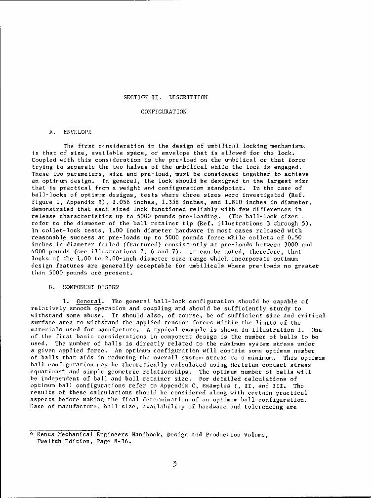
1. General. The general ball-lock configuration should be capable ofrelatively smooth operation and coupling and should be sufficiently sturdy towithstand some abuse. It should also, of course, be of sufficient size and criticalsurface area to withstand the applied tension forces within the limits of thematerials used for manufacture. A typical example is shown in illustration 1. Oneof the first basic considerations in component design is the number of balls to beused. The number of balls is directly related to the maximum system stress undera given applied force. An optimum configuration will contain some optimum numberof balls that aids in reducing the overall system stress to a minimum. This optimumball configuration may be theoretically calculated using Hertzian contact stressequations* and simple geometric relationships. The optimum number of balls willbe independent of ball and ball retainer size. For detailed calculations ofoptimum ball configurations refer to Appendix C, Examples T, II, and III. Theresults of these calculations should be considered along with certain practicalaspects before making the final determination of an optimum ball configuration.Ease of manufacture, ball size, availability of hardware and tolerancing are
* Kents Mechanical Engineers Handbook, Design and Production Volume,
Twelfth Edition, Page 8-36.
35
some of these additional considerations. Based on these considerationsand the above mentioned calculations, the ideal number of balls to be usedfor any sized ball-lock of the type applicable for space vehicle umbilicalshas been determined to be four.
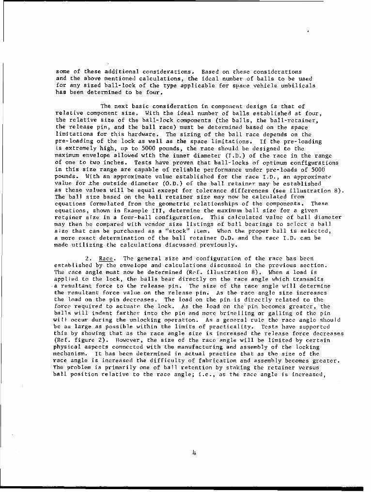
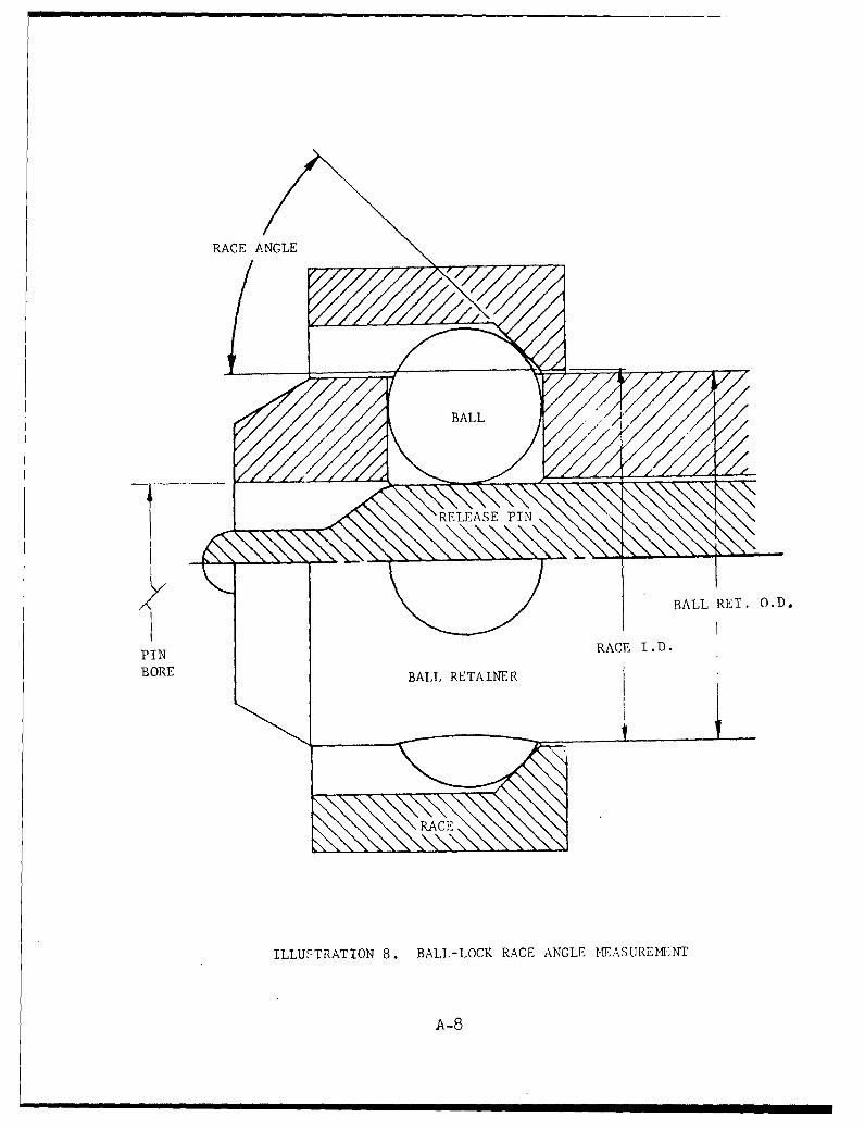
The next basic consideration in component design is that ofrelative component size. With the ideal number of balls established at four,the relative size of the ball-lock components (the balls, the ball-retainer,the release pin, and the ball race) must be determined based on the spacelimitations for this hardware. The sizing of the ball race depends on thepre-loading of the lock as well as the space limitations. If the pre-loadingis extremely high, up to 5000 pounds, the race should be designed to themaximum envelope allowed with the inner diameter (T.D.) of the race in the rangeof one to two inches. Tests have proven that ball-locks of optimum configurationsin this size range are capable of reliable performance under pre-loads of 5000pounds. With an approximate value established for the race I.D., an approximatevalue for the outside diameter (O.D.) of the ball retainer may be establishedas these values will be equal except for tolerance differences (see illustration 8).The ball size based on the ball retainer size may now be calculated fromequations formulated from the geometric relationships of the components. Theseequations, shown in Example III, determine the maximum ball size for a givenretainer size in a four-ball configuration. This calculated value of ball diametermay then be compared with vendor size listings of ball bearings to select a ballsize that can be purchased as a "stock" item. When the proper ball is selected,a more exact determination of the ball retainer O.D. and the race I.D. can bemade utilizing the calculations discussed previously.
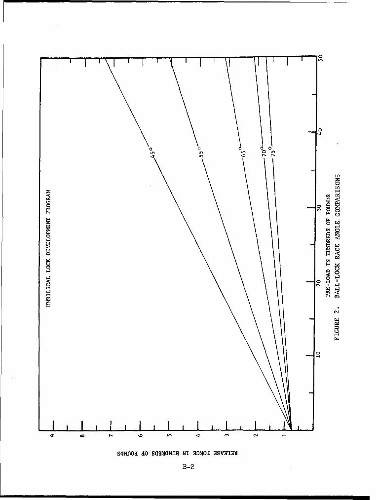
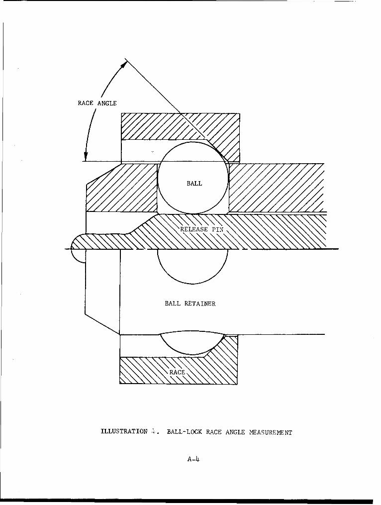
2. Race. The general size and configuration of the race has beenestablished by the envelope and calculations discussed in the previous section.The race angle must now be determined (Ref. illustration 8). When a load isapplied to the lock, the balls bear directly on the race angle which transmits*a resultant force to the release pin. The size of the race angle will determinethe resultant force value on the release pin. As the race angle size increasesthe load on the pin decreases. The load on the pin is directly related to theforce required to actuate the lock. As the load on the pin becomes greater, theballs will indent farther into the pin and more brinelling or galling of the pinwill occur during the unlocking operation. As a general rule the race angle shouldbe as large as possible within the limits of practicality. Tests have supportedthis by showing that as the race angle size is increased the release force decreases(Ref. figure 2). However, the size of the race angle will be limited by certainphysical aspects connected with the manufacturing and assembly of the lockingmechanism. It has been determined in actual practice that as the size of therace angle is increased the difficulty of fabrication and assembly becomes greater.The problem is primarily one of ball retention by staking the retainer versusball position relative to the race angle; i.e., as the race angle is increased,
4
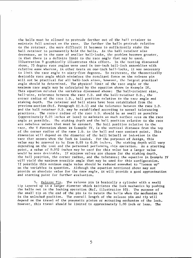
the balls must be allowed to protrude farther out of the ball retainer tomaintain full contact on the race. The farther the balls protrude relativeto the retainer, the more difficult it becomes to sufficiently stake theball retainer to permanently hold the balls. As the ball retainer sizedecreases, as in the case of smaller ball-locks, the problem becomes greater,in that there is a definite limit to the race angle that may be used.Illustration 9 graphically illustrates this effect. In the testing 'discussedabove, 75 degree race angles were used in two-inch ball-lock assemblies withrelative ease whereas, in other tests on one-inch ball-locks, it was necessaryto limit the race angle to sixty-five degrees. To reiterate, the theoreticallydesirable race angle which minimizes the resultant force on the release pinwill not be practical for all ball-lock sizes, however, the largest practicalangle should be determined. The physical limit of the race angle or themaximum race angle may be calculated by the equation shown in Example IV.This equation relates the variables discussed above: The ball-retainer size,ball-size, tolerance between the race I.D. and the ball-retainer O.D., thecorner radius of the race I.D., ball position relative to the race angle andstaking depth. The retainer and ball sizes have been established from theprevious section (Ref. Paragraph II.B.l) and the tolerance between the race I.D.and the ball retainer O.D. may be established according to normal tolerancingpractices. The corner radius of the race I.D. should be as small as possible(approximately 0.03 inches or less) to maintain as much surface area on the raceangle as possible. The staking depth and the ball position relative to the raceare nebulous values that must be assumed. The ball position relative to therace, the Y dimension shown in Example IV, is the vertical distance from the topof the corner radius of the race I.D. to the ball and race contact point. Thisdimension will depend on the diameter of the ball brinell or indention in therace that occurs when the lock is loaded. For the purposes of design, thisvalue may be assumed to be from 0.03 to 0.04 inches. The staking depth will varydepending on the too[ and the personnel performing this operation. As a startingpoint, a value oF 0.032 inches may be used for this value but a larger valuewould be more desirable. If minimum values are chosen for the staking depth,the ball position, the corner radius, and the tolerance; the equation in Example IVwill yield the maximum possible angle that may be used for this configuration.If possible this maximum angle value should be reduced somewhat to "loosen up"on the variables in question. Although the equation mentioned above may notprovide an absolute value for the race angle, it will provide a good approximationand starting point for further evaluation.
3. Release Pin. The release pin is basically a cylinder with a smalltip tapered up to a larger diameter which initiates the lock mechanics by pushingthe balls out in the locking operation (Ref. illustration 10). The purpose ofthe small tip on the end of the pin is to retain the balls when the mechanism isin the unlocked position. The overall length of the release pin and tip willdepend on the travel of the pneumatic piston or actuating mechanism of the lock.However, this travel should be limited to approximately 1.00 inch or less. The
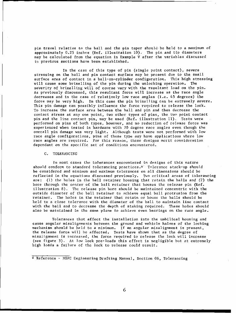
pin travel relative to the ball and the pin taper should-be held to a maximum ofapproximately 0.25 inches (Ref. illustration 10). The pin and tip diametersmay be calculated from the equation in Example V after the variables discussedin previous sections have been established.
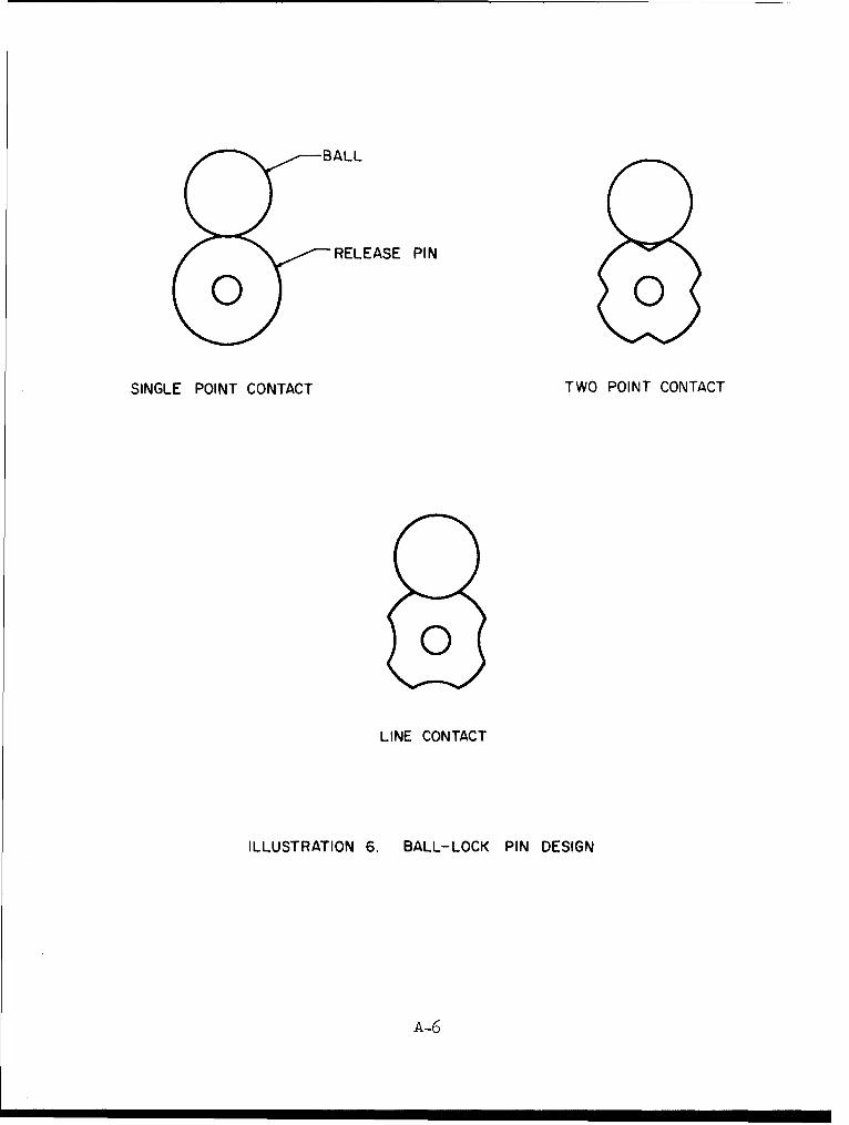
In the case of this type of pin (single point contact), severestressing on the ball and pin contact surface may be present due to the smallsurface area of contact in a ball-on-cylinder configuration. This high stressingwill cause some brinelling of the pin during the unlocking operation. Theseverity of brinelling will of course vary with the resultant load on the pin.As previously discussed, this resultant force will increase as the race angledecreases and in the case of relatively low race angles (i.e. 45 degrees) theforce may be very high. In this case the pin brinelling can be extremely severe.This pin damage can possibly influence the force required to release the lock.To increase the surface area between the ball and pin and thus decrease thecontact stress at any one point, two other types of pins, the two point contactpin and the line contact pin, may be used (Ref. illustration 11). Tests wereperformed on pins of both types, however, and no reduction of release force wasexperienced when tested in hardware with 70 degree race angles even though theoverall pin damage was very light. Although tests were not performed with lowrace angle configurations, pins of these type Lnay have applications where lowrace angles are required. For this reason, these designs merit considerationdependant on the specific set of conditions encountered.
C. TOLERANCING
In most cases the tolerances encountered in designs of this natureshould conform to standard tolerancing practices.* Tolerance stack-up shouldbe considered and minimum and maximum tolerances on all dimensions should bereflected in the equations discussed previously. Two critical areas of tolerancingare: (1) the holes in the ball retainer housing that retain the balls and (2) thebore through the center of the ball retainer that houses the release pin (Ref.illustration 8). The release pin bore should be maintained concentric with theoutside diameter of the ball retainer to achieve equal ball protrusion from theretainer. The holes in the retainer that retain or house the balls should beheld to a close tolerance with the diameter of the ball to maintain line contactwith the ball and to decrease the depth of staking required. These holes shouldalso be maintained in the same plane to achieve even bearings on the race angle.
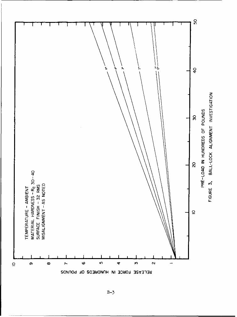
Tolerances that affect the installation into the umbilical housing andcause angular misalignments between the ground and vehicle halves of the lockingmechanism should be held to a minimum. If an angular misalignment is present,the release force will be affected. Tests have shown that as the degree ofmisalignment is increased, the force required to release the lock will increase(see figure 3). At low lock pre-loads this effect is negligible but at extremelyhigh loads a failure of the lock to release could result.
* Reference - MSFC Engineering Drafting Manual, Section 06, Tolerancing
6
'•TERIALS
A. GENERAL
In the selection of materials for locking mechanism components, twoof the most important considerations are pre-load or stressing and environment.
In applications of this type where contact stresses are present and pre-loadsare high, extremely high stresses will be experienced. In most cases, materialsare not available that will withstand this high stressing without some damage.Stresses of several hundred thousand pounds per square inch on ball-lock componentscan be expected when pre-loads of 5000 pounds or more are applied to the lock.However, in contact stressing only the surface of the part is stressed and onlysurface damage will result. This surface damage must be held to a minimumto maintain release forces at a reasonable level and, therefore, very strongmaterials must be used. In most cases harder materials effect the best resultsin applications of this type. In addition, surface damages must be restrictedto certain areas in the locking device. For example, if the balls were made ofa very soft material, they would deform or flatten out under high loads andrelease would be greatly affected. Generally, it is preferable if the ballsare maintained as the hardest components in the ball-lock assembly and thesurface damage limited mainly to the race and rdlease pin.
Environment is also an important factor in the selection of materials.All materials used must be compatible with the environment to which they areexposed. In space vehicle applications, materials may be subjected to a cor-rosive environment, a liquid oxygen (LOX) environment, extreme temperatureenvironments, etc. It may be required that the materials be compatible withall of these conditions.
Stainless steels are best suited for applications of this type becauseof their high strength and corrosion resistance. Stainless steel, type 440C.is an excellent ball material and can be heat treated to a very hard condition(Rockwell C (Rc) 58 or harder). Since this material is a standard ball bearingmaterial, balls can be readily purchased in all sizes. All 400 series stainlesssteels, however, become extremely brittle at low temperatures and may not bedesirable for cryogenic applications. Although in all tests performed in theassociated test program (nearly 4000 tests in all) at temperature as low asminus 196 0 C using 440C balls, no failures, fractures or serious damage occurreddue to the ball material. Since contact stresses result in stressing on thecomponent surface only and a ball configuration does not readily lend itselfto fracture, it is felt that the use of 440C stainless steel as a ball materialwill not result in any serious problems at reduced temperatures.
300 series stainless steels such as 304 and 303 can be used for othercomponent materials (race, release pin, ball retainer). Stainless steel type 304has exceptionally good low temperature properties. However, all 300 series steelsmust be purchased in a prehardened condition by cold working and are not readily
7
available in very hard conditions. The hardness limit is approximatelyRc 35 and is very difficult to obtain. 17-4 PH stainless steel is an agehardenable stainless steel and can be purchased in various hardness conditions.This material is recommended when a 300 series stainless steel is not availableat a desired hardness level. hqteenercenJk 68%) nickel maraging steel isan ultra-high strength material which can be heat treated to a hardness ofapproximately Rc 50 and an ultimate strength of approximately 250,000 poundsper square inch. This material performs very well as a component material ina ball-lock assembly. However, this material at the present time is comparativelyexpensive and is not corrosion resistant. A protective coating or plating wouldbe required for use in a corrosive atmosphere. For these reasons this materialwould not be recommended unless very high strengths are required due to excessivepre-loads on the ball-lock. Various other materials may be applicable but theyshould be selected to be compatible with the specific set of conditions underwhich they will be use.Li
B. MATERIAL HARDNESS
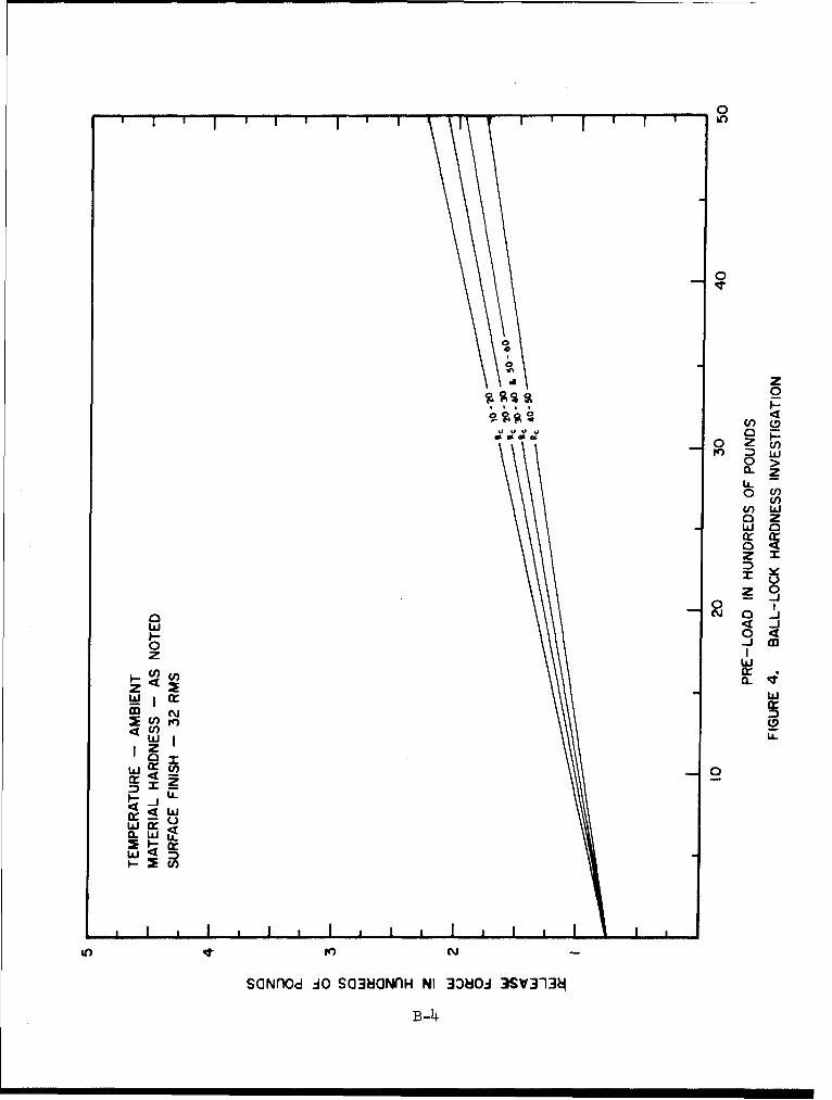
In.ball-lock design, the material hardness is generally more importantthan the type of material in so far as the unlocking operation or force requiredto-unlock is concerned. As previously stated, very high surface stresses may beencountered in the use of ball-locks and to minimize surface damage, hard materialsare required. Tests have shown that as the material hardness increases, the forcerequired to release the lock decreases (Ref. figure 4). In addition the releaseforce data obtained in tests of this type was much less scattered and morereproducible when harder materials were tested. In cryogenic temperature appli-cations, soft materials become harder and release forces become comparable withthose where hard materials are used. However, based on past experience, the mostfavorable results will be achieved when the hardness of the race, release pinand ball retainer is maintained above Rc 25 and the ball material is maintainedabove Rc 50. The exact hardness level required will depend on the specific serviceconditions, primarily the overall load on the lock. When the pre-load does notexceed 5000 pounds the above hardness recommendations will apply.
C. HARDWARE LIFE
Hardware life will basically be affected by material hardnesses. Sinceball-lock components will suffer some surface damage, repeated use of the samehardware may cause some problems if the materials used are too soft. When lifecycle tests, shown in figures 5 and 6, were performed on ball-lock assemblies withcomponents of two hardnesses, the data was more consistant where the hardermaterial was tested. No failures to release, however, were experienced in eithertest series of 250 cycles. When lower race angles than the 70-degree angles usedin these tests are required, the release forces are likely to be more inconsistentand the possibility of failure after repeated cycling will be greater. Basically,the use of the hardest materials available that are practical for this applicationand can be acquired both readily and economically will increase the overall reli-ability of the locking mechanism.
SURFACE CONDITIONING
A. SURFACE FINISH
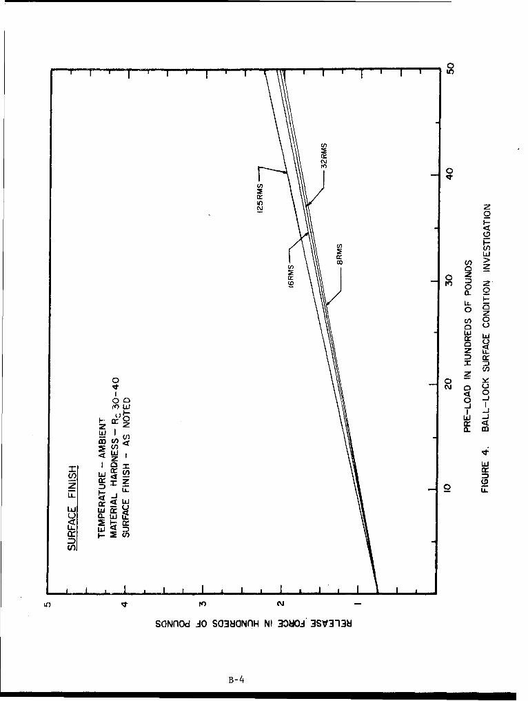
To achieve an optimum ball-lock design, the proper surface finishmust be selected for each component of the assembly. Since the bearing surfacesof the race and release pin even in an optimum configuration will receive moderatedamage during the unlocking operation, the difference in the effect of surfacefinishes of 8 root mean square (rms) to 32 rms on these components is negligibleas release force is concerned (see figure 7). In addition, only slightly higherrelease forces will be obtained when surface finishes as high as 125 rms are used.A 32 rms finish is recommended for the bearing surfaces of the above hardware sinceit is easily achieved by normal machine shop procedures and is quite acceptablefrom a release standpoint. The surface finish of the balls on the other handshould be maintained as low as possible. Past experience has shown that thesurface condition of the balls will greatly affect the release characteristicsof the lock such that it may be required that the balls be replaced frequentlyduring repeated use. Standard precision grade bearing balls conforming to MilitaryStandard MS 9461 can be purchased economically with a 2 rms surface finish and arerecommended for this application due to past performances. Even when using ballsof this type a transfer of material from the release pin to the balls under highloads may occur that will require replacement of the balls for continued use of
the lock assembly.
B. PLATING
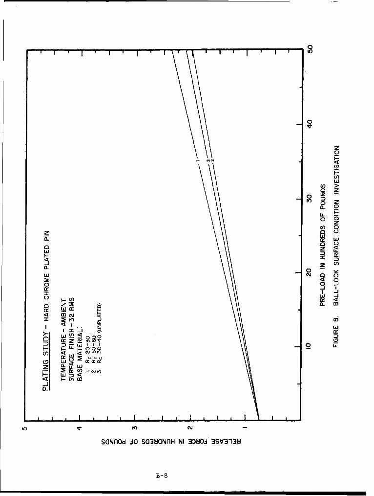
A protective plating on lock hardware will be required when materialsthat are not corrosion resistant are required for applications where a corrosiveatmosphere is present. A plating of this type will not affect the overall operationof the lock. Tests have supported that release forces are neither reduced norincreased due to plating effects when optimized ball-lock designs are used. Whenless than optimum designs are used and loads on the plated parts are sufficient tocause severe surface damage, the reliability of the lock may be affected due toflaking of the plating material. In situations where the lock is required toundergo an excessive number of release cycles, the reliability of the lock mayalso be affected due to plating damage.
C. LUBRICATION
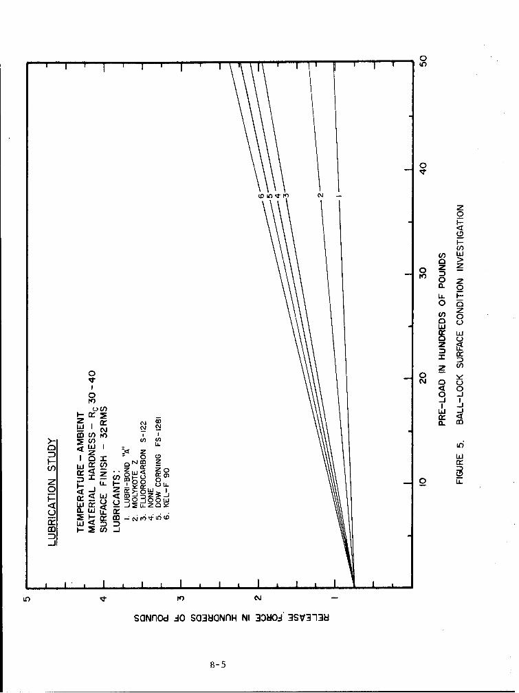
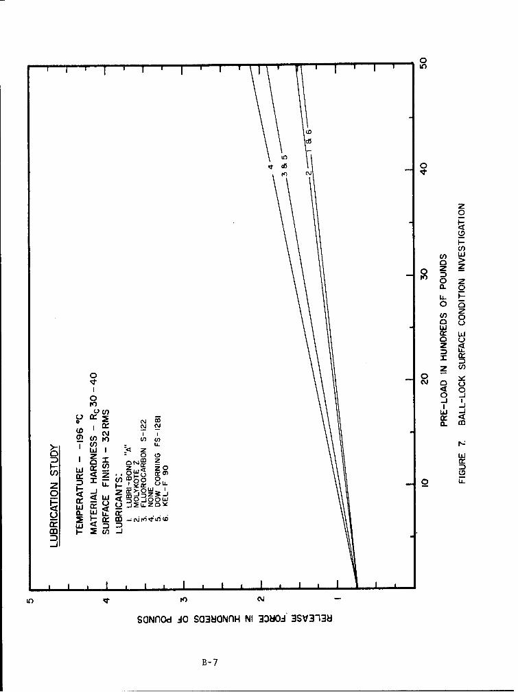
Ball-locks of an optimum design do not require lubrication on the bearingsurface to function reliably. However, the use of certain types of lubricants willsignificantly affect the release characteristics of the lock such that very littleforce is required to release the lock. This was demonstrated in tests where theeffect of lubrication was investigated and the results compared with data wherelubrication was not used (see figure 8). These tests also demonstrated that onlydry film type or spray film type lubricants showed any improvements over unlubricatedsystems for this type of application. The data from the tests where grease typelubricants were used was only comparable to and in some cases higher than the testdata where no lubrication was used.
9
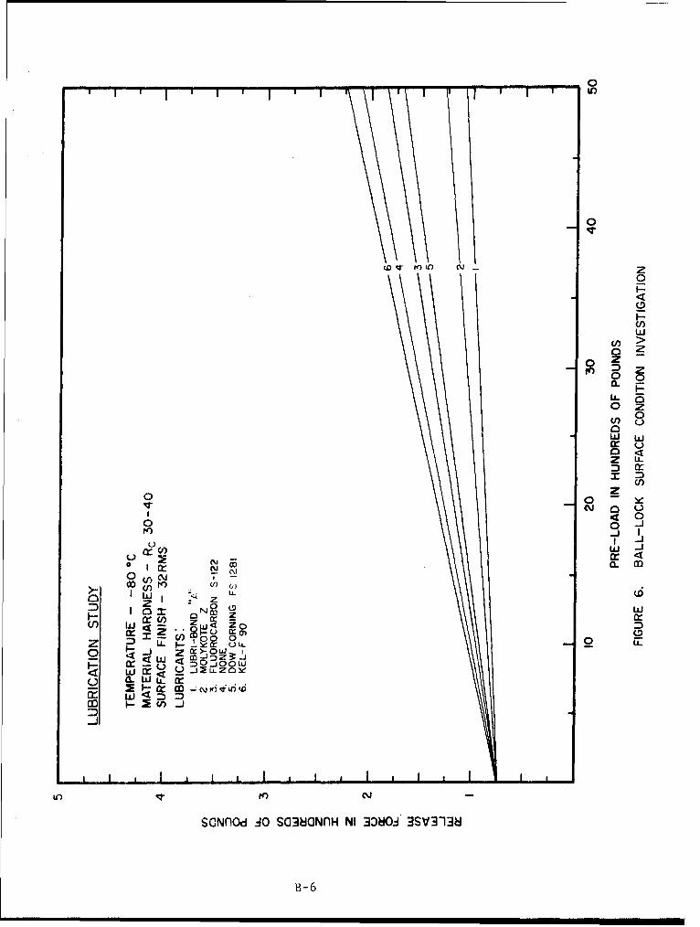
As in the case of material selection, lubricants must be compatiblewith the environment to which they are exposed. When the lock assembly is subjectto cryogenic temperatures, dry film type lubricants produce the best results.When exposed to liquid oxygen (LOX), the lubricant must of course be compatiblewith LOX. The lubricant which produced the lowest release forces in the previouslydiscussed test program, Electrofilm Lubri-Bond A, was not LOX compatible and,therefore, could not be used for most space vehicle applications. Other lubricantsof the same type are available which will conform to the necessary requirements.As stated before, however, lubrication is not necessary unless very low releaseforces are desired.
10

APPENDIX A - ILLUSTRATIONS
SPNEUMATIC CYLINDER
L,
I .BALL RETAINER • ••
S)
' • :. RACE :)'<*• •
.. •:i•';;• r
BALL---JO
PIN TIPiILLUSTRATION I. BALL-LOCK (2 INCIT)
A-Z
COLLET
ILLUSTRATION 2. COLLET-LOCK (1INCHl)
A-2
I
ILLUSTRATION 3. BALL-LOCK (1 1/2 INCH)
A-3
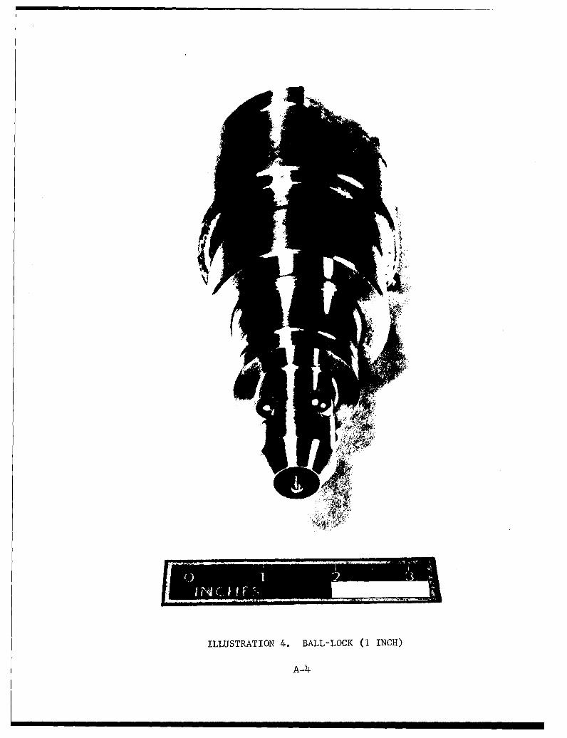
ILLUSTRATION 4. BALL-LOCK (1 INCH)
A-4-
'-40-4
-4
0
0
�0
0
z0
* H
0(�) 00'-4
H('4 cf�
'--4C.)
'-4 0'-4
*0
o0:,
Lf*�
-�0
H
'-4-4
* H
C-)0-4
('4'-A
0
0
--4co
A-5
rr
E-,0
0
H
E-4z
H
A-6
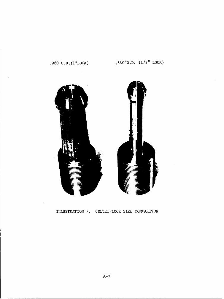
.980"O.D.(I"LOCK) .630"O.D. (1/2" LOCK)
ILLUSTRATION 7. COLLET-LOCK SIZE COMPARISON
A-7
RACEANL
BALL RET •.•D.
PIN RACE I.D.
BORE BALL RETAINER
ILLUSTRATION 8. BALL-LOCK RACE ANGLE MPASUREMENT
A-8
L!x L
450 RACE 550 RACE
x
650 RACE 750 RACE
POINT OF CONTACTX MATERIAL ALLOWANCE FOR STAKING
(REFER TO ILLUSTRATION 8 FOR ORIENTATION & PART IDENTIFICATION)
ILLUSTRATION 9. RACE ANGLE SIZE VERSUS BALL RETENTION
A-9
PIN TRAVEL RELATIVETO BALL AND PINTAPER
SPHERICAL\RADIUS 350 REF I'
ILLUSTRATION 10. BALL-LOCK RELEASE PIN
A-10
BALL
RELEASE PIN
0 0SINGLE POINT CONTACT TWO POINT CONTACT
a0
LINE CONTACT
ILLUSTRATION II. BALL-LOCK PIN DESIGN
A-1l
APPENDIX B - GRAPHS
-41
z
1-44
44d
00
-B-
0 0 0 0 0IF* V L/n 0 Lfn
tn r- r-
CA
1-4I
1-4
000
B-2
0
V)n
zzw0
L.L 2
_j0 Z
a.~c w -J-< ~cr (n
OI r-
SO~nd A S03O~n NI 080 3SV-10
o B-3
0U-)
0
In
A z0
rr w
D W
I>WI U-
Izz
0
U') Nr
SOz ~ 4O CLGfHN D~~3V1~
W I cB-4
_0
z
wo
o w
- Li
co Io
w I L
< U) __ I
0 a
ZI
cr <
Z-~) XL_ _ _
0 0 0 0 0 0 0 0m ID (D LOI nN
(SONflod) 3380 3SV3ri3
B-5
___ 10
0
0
___ w
0
U) 0w )
0 - _
4-mCD
WI
W ~cflU
0 ý 0i 0- 00
00 0 0 0 0 0_
(SONflOd) 30801 3SV3138i
B-6
0
0
U)
z0
0
ir.
c Cd) 0:C)
CL,
z
000
W LJWI
UL)
0
C) r OwL
If) N
SOfL LOS3Gfl I3JOi~~1

z0
LI-
o>
o Z
05Ez
M00
a L)
0-J
00 ýWI
Z 0 -1
!L~J o Z C\J CL M
o o O-WuoSCl r CD
W I U- I I i II
1) i') U) -n z
SMf~ cO SO4~l NI .. ~i. z SV3TZ
z OW< crB-8
APPENDIX C - CALCULATIONS
The basic equation developed by H. Hertz for determining contact stress in asphere-on-plane configuration is as follows:
3 ýPE02S O.616.ý
Where:
S StressP LoadE Modulus of Elasticityd Sphere diameter
(Reference: Kent's "Mechanical Engineers' Handbook", Design & Production,
Twelfth Edition, pages 8-36)
Or:
3Pr ES = 0.616 E Equation (I)
4r12
Where:
Pr = Force on Ball-Lock Racer, = Radius of Ball
From the force diagram: (See page C-4)
pr = FtA, Equation (2)N
Where:
Ft = Total load on Ball-LockN = Number of BallsA, = Constant
EXAMPLE I. OPTIMUM BALL NUMBER DETERMINATION.
C-1
From the ball and ball retainer relationship: (See page C-6)
ri aR Equation (5)
Where:
R Ball retainer radius
and:
a s.N..l Equation (4)
1 + sin(N)
Substituting from Equations (2) and (5) in Equation (I)
S = 0.616 4A, Ft E Equation (6)'V4Na2R2
Letting A,, E, Ft and R be Constants:
S= KI,/•-•o Equation (7)
Where:
K, = Accumulated Constants
Thus indicating that stress(s) is minimum when Nat is maximum
And letting A,, E, S and R be Constants:
Ft = KNa' Equation (8)
Where:
Kp = Accumulated Constants
Thus indicating that, for a given stress(s), the total force on the lock (Ftwill be maximum when Na' is maximum.
EXAMPLE I. (Continued)
C-2
Solving for a and Nap for various numbers of balls (N) results in the fol-
lowing table:
(Ref: Equation 4)
N Q Nra 2
2 0.5000 0.5003 0.4640 0.6459
1 4 0.4142 0.68645 0.370o 0.68506 0.3333 0.66677 0.3026 0.64128 0.2767 0.61289 0.2548 0.584110 0.2360 0.557012 0.2055 0.506414 0.1819 0.4364
Therefore:
When the number of balls is four, the Na! value is maximumand from Equation (7) the stress on the race will be minimum.
EXAMPLE I. (Concluded)
C-3
I/ I PrPr
FORCE DIAGRAM
F = Applied force on each ball
Ft Total applied force on lock
N = Number of balls
Pr Resultant force on racePI) Resultant force on pin
A, P/2 /A3 Coefficient of friction onrespective surfacesF = F-
F =- 3 Pp+ Prsina +/,IPrcOsa
Or:F - Pr sin a -j/ 1 Pr cos a
EXAMPLE 1E. FORCE DIAGRAM
C-4
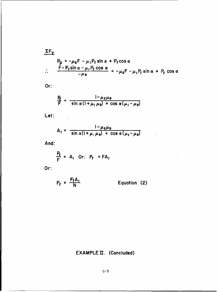
I Fy
pp = -IL2 F - IL I Pr sin a + Pr COS a-F- Prsin a - ILI Pr COS a = -ýtpF -,ýLj Pr sin a + Pr COS a
Or:
ILW3
F sin a 0 + ýL I ;L3) + COS a (ILI IL3)
Let:
A, sin a 0 +,ul u3) + COS a
And:
Pr A, Or: Pr = FAIF
Or:
FtA, Equation (2)Pr N
EXAMPLE 11. (Concluded)
C-5
BALL RETAINER
\ r1
RELEASE PIN TIP
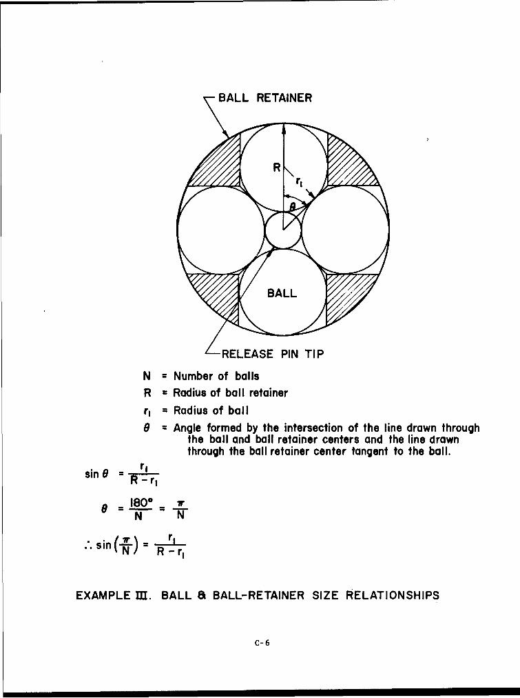
N = Number of balls
R = Radius of ball retainerr, = Radius of ball
6 = Angle formed by the intersection of the line drawn throughthe ball and ball retainer centers and the line drawnthrough the ball retainer center tangent to the ball.
sin 8 reR -r,
o = 1rN -W"
..sin 7r- r rINR - r
EXAMPLE III. BALL 8 BALL-RETAINER SIZE RELATIONSHIPS
C-6
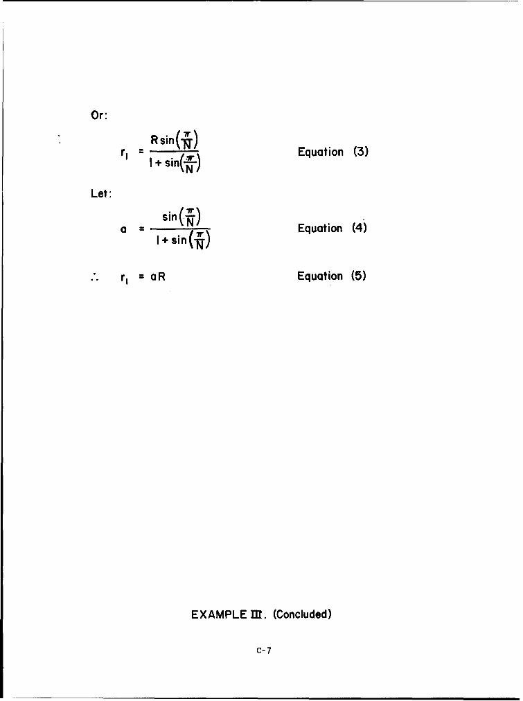
Or:
rI sin(tN. Equation (3)
Let:
a sin(7) Equation (4)l+ sin (i*)
r= aR Equation (5)
EXAMPLE MT. (Concluded)
C-7
r, (I-cos a)
r(I -cos a){ r, r, cos a
t
S
R
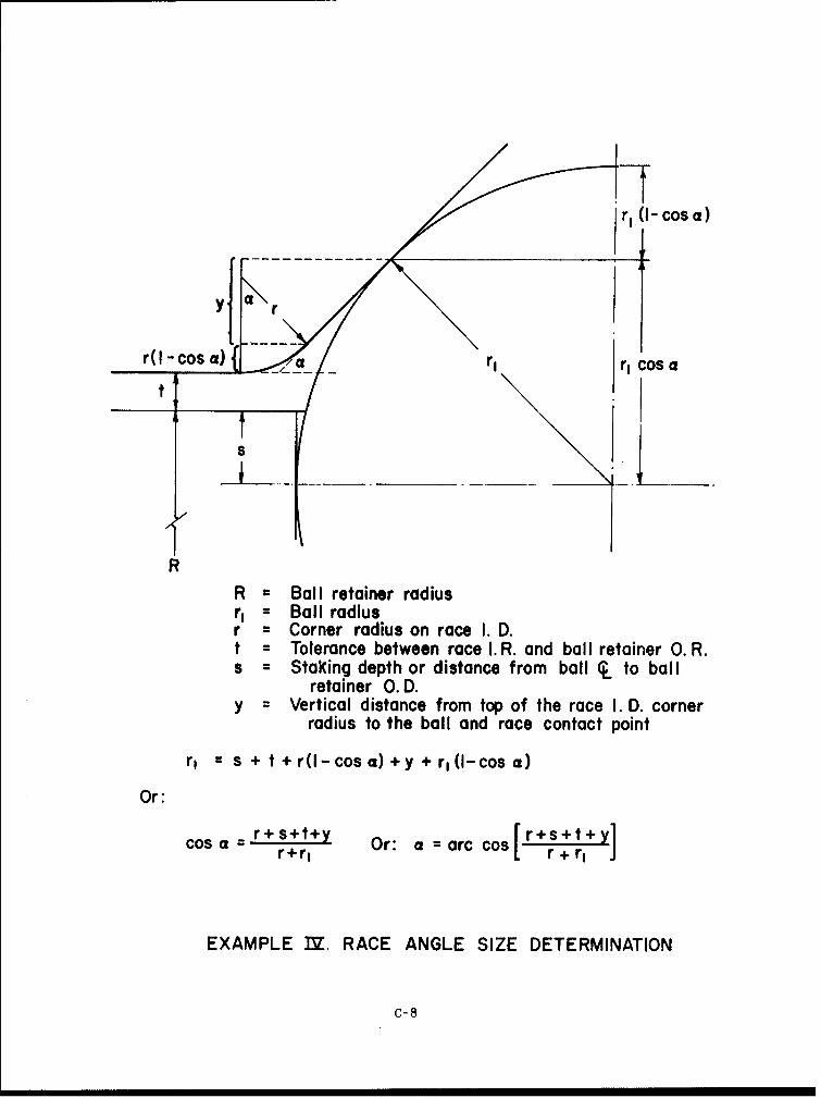
R = Ball retainer radiusr, =Ball radiusr = Corner radius on race I. D.t= Tolerance between race I. R. and ball retainer 0. R.s = Staking depth or distance from ball Q to ball
retainer O.D.y = Vertical distance from top of the race I. D. corner
radius to the ball and race contact point
r, = s +t+r(l-cosa)+y+r,(l-cosa)
Or:
cos a= r+s+t+y Or: a =arc cos [r+s + t+yr+rI r + r,
EXAMPLE TY. RACE ANGLE SIZE DETERMINATION
C-8
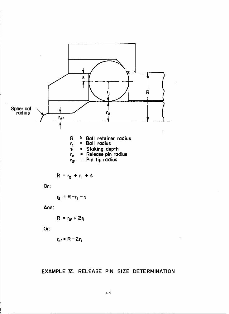
R
Sphericalrad ius r.
rf
R - Ball retainer radiusr, = Ball radiuss Staking depthr== Release pin radiusr., = Pin tip radius
R rp + r, + s
Or:
r, R -r, - s
And:
R r2 +2r,
Or:
r.= R - 2r,
EXAMPLE V. RELEASE PIN SIZE DETERMINATION
C-9
ADDENDUM
FINAL TEST REPORT OF
UMBILICAL LOCKING MECHANISM
DEVELOPMENT PROGRAM
29 MARCH 1967
PREPARED FOR
THE GEORGE C. MARSHALL SPACE FLIGHT CENTER
NATIONAL AERONAUTICS AND SPACE ADMINISTRATION
HUNTSVILLE, ALABAMA
TEST REPORT
CONTRACT NUMBER - NAS8-20649
REQUEST NUMBER - DCN 1-6-51-01183 (IF)
PREPARED BY
DAVID L. CUSICK
ELECTRICAL SYSTEMS AND GSE ENGINEERING DEPARTMENTCHRYSLER CORPORATION SPACE DIVISION
1312 NORTH MERIDIAN STREET
HUNTSVILLE, ALABAMA 35807
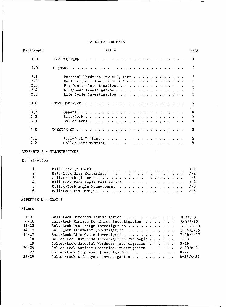
TABLE OF CONTENTS
Paragraph Title Page
1.0 INTRODUCTION .................. .. ....................... 1
2.0 SUMMARY ..................... .. ....................... 2
2.1 Material Hardness Investigation ......... ............ 22.2 Surface Condition Investigation ..................... 22.3 Pin Design Investigation ........... ................ 32.4 Alignment Investigation .................. .. ...... 32.5 Life Cycle Investigation .............. .............. 3
3,0 TEST HARDWARE ...................... ....................... 4
321 General ...................... ........................ 43.2 Ball-Lock ..................... ....................... 43,3 Collet-Lock ................. .. ............... 4
4.0 DISCUSSION ..................... . ......................... 5
4.1 Ball-Lock Testing ............... ................... 54.2 Collet-Lock Testing ............... .................. 8
APPENDIX A - ILLUSTRATIONS
Illustration
1 Ball-Lock (2 Inch) ............ ..................... .. A-12 Ball-Lock Size Comparison .............. ............ A-23 Collet-Lock (I Inch) ... ............... ............ A-34 Ball-Lock Race Angle Measurement ........ ............ .. A-45 Collet-Lock Angle Measurement ....... ............... .. A-56 Ball-Lock Pin Design .................... A-6
APPENDIX B - GRAPHS
Figure
1-3 Ball-Lock Hardness Investigation ..... ............ .. B-I/B-34-10 Ball-Lock Surface Condition Investigation ........ B-4/B-IO
11-13 Ball-Lock Pin Design Investigation ...... ........... B-II/B-1314-15 Ball-Lock Alignment Investigation .... ........... .. B-14/B-1516-17 Ball-Lock Life Cycle Investigation .... ........... .. B-16/B-17
18 Collet-Lock Hardness Investigation 750 Angle ...... .. B-1819 Collet-Lock Material Hardness Investigation .... . . B-19
20-26 Collet-Lock Surface Condition Investigation ...... .. B-20/B-2627 Collet-Lock Alignment Investigation ... ........... B-27
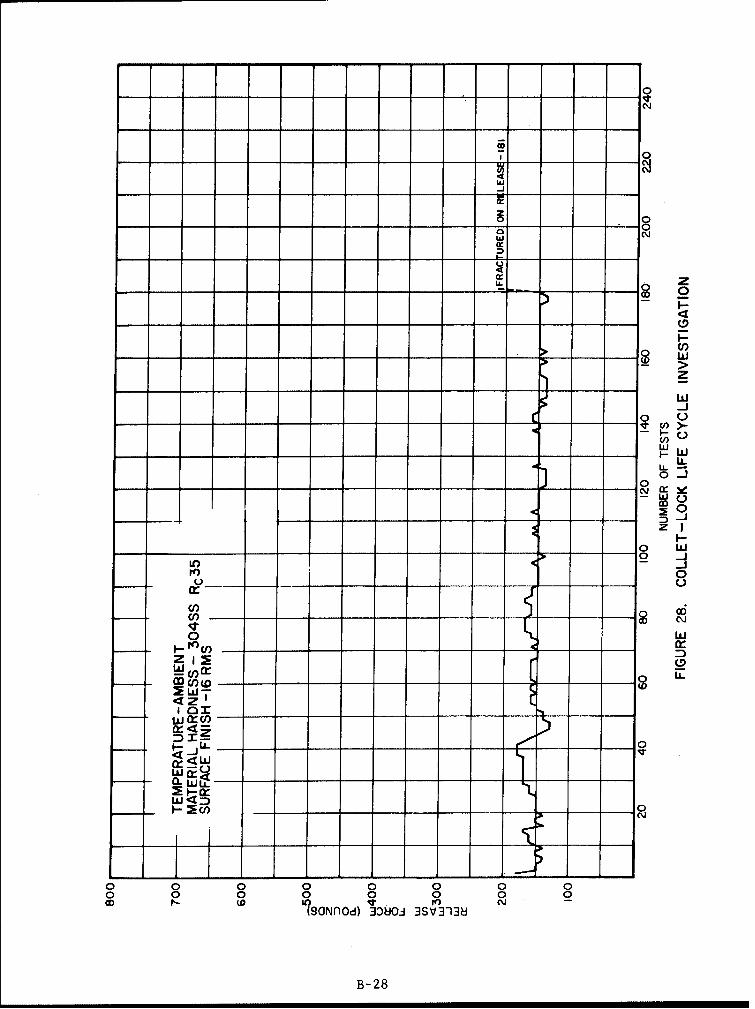
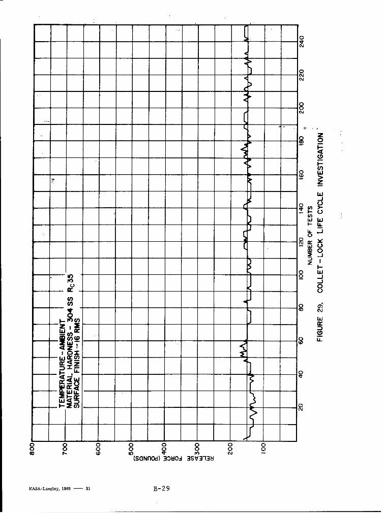
28-29 Collet-Lock Life Cycle Investigation ....... . B-28/B-29
1.0 INTRODUCTION
This report covers the results of Phase II of a test program conductedfor the Umbilical and Disconnects Section of the Propulsion and Vehicle EngineeringLaboratory of Marshall Space Flight Center, Huntsville, Alabama, under ContractsNAS8-4016, Mod. 206 and NAS8-20649. The purpose of the program is to establishthe criteria necessary in the design, the selection, and the acceptance oflocking mechanisms applicable for space vehicle umbilical carriers. Tests wereperformed on two basic types of locking mechanisms to determine the effect ofcertain significant parameters on release force and reliability. In Phase Iof the program, conducted and reported under Contract NAS8-4016, Mod. 206,the parameters investigated were: (1) race angle, (2) lock size, (3) materials,(4) material hardness, and (5) temperature. Phase II of the program wasconcerned with : (i) additional investigation in the areas of materials andmaterial hardness, (2) surface conditioning, (3) release pin design, (4) alignment,and (5) hardware life. In both phases of the program experimental hardware wastested at loadings up to 8000 pounds and temperatures as low as minus 196degrees centigrade (OC).
This report is limited to the results of the testing accomplished inPhase II of this program. All curves and data comparisons shown in thisreport were statistically generated from the raw data obtained in this testprogram. All data was transposed to the same zero point for ease of comparisonand should be used for comparison purposes only.
2.0 SUMMARY
2.1 MATERIAL HARDNESS INVESTIGATION
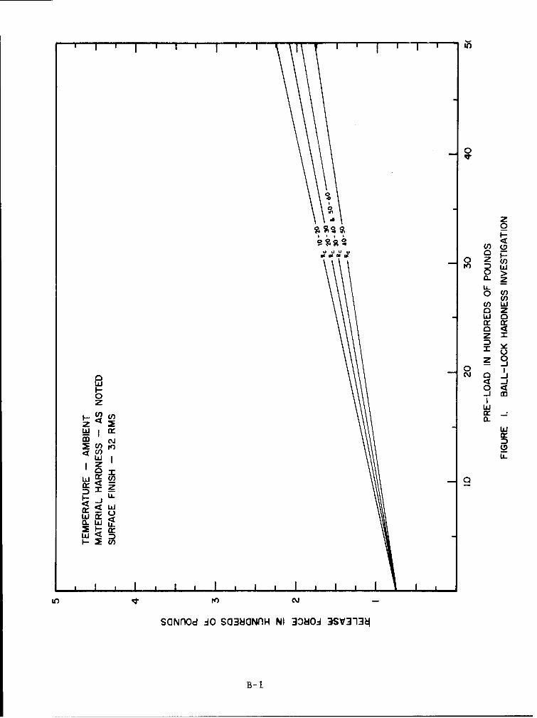
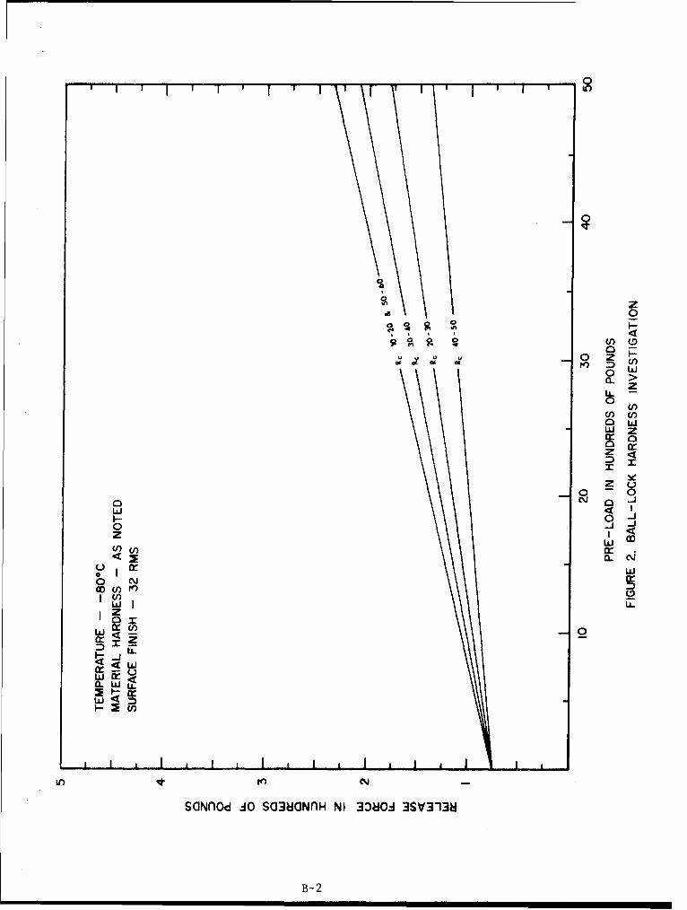
Ball-lock and collet-lock component material hardnesses in theranges of Rockwell C (Rc) 10-20, 20-30, 30-40, 40-50, and 50-60 were investigated.The materials used to obtain these hardness levels were 304 stainless steel,17-4PH stainless steel, 18% nickel maraging steel, and beryllium copper. Colletsof beryllium copper at three hardness levels (Rockwell B (Rb) 60, Rb 75, andRc 45) have also been tested. In most cases, the lowest release forces wereobtained where the harder materials were used.
2.2 SURFACE CONDITION INVESTIGATION
2.2.1 Surface Finish.
Ball-lock and collet-lock configurations with component surfacefinishes of 8, 16, 32 and 125 root mean square (rms) were tested. The resultingrelease forces were directly proportional to the surface finish with the highestrelease forces resulting in the 125 rms tests, however, the only significantdifferencesin release forces were obtained in the collet-lock tests.
2.2.2 Lubrication
Five lubricants were tested on both ball-lock and collet-lockconfigurations. These lubricants were Molykote Z, a dry powder; ElectrofilmLubri-Bond A, a molybdenum disulfide spray film; Fluorocarbon S-122, a teflonspray film; Dow Corning FS 1281 grease; and KEL-F No. 90 grease. These lubricantswere selected for their liquid oxygen (LOX) compatibility and/or low temperatureproperties. Release forces were always reduced where the spray type lubricantswere used. The lowest release forces were obtained in the tests using theLubri-Bond A lubricant.
2.2.3 Plating
In these tests the effects of a hard chrome plate on the releasepins of ball-lock and collet-lock assemblies were investigated. The plating ofthe pin did not have any significant affect on the release characteristics ofthe locks. The release forces obtained in these tests were comparable with theresults of tests performed where no plating was used. However, no flaking orextreme damage to the chrome plate was observed in these tests.
2
2.3 PIN DESIGN INVESTIGATION
Two types of ball-lock release pins, a two point contact designand a line contact design, were tested. When compared to the results of testswhere a conventional' release (single point contact) pin was used, the releaseforces obtained in these tests proved to be high. Considering this alongwith the additional problems involved in the manufacture of pins of thesetypes, it is felt that these designs do not merit any further consideration.
2.4 ALIGNMENT INVESTIGATION
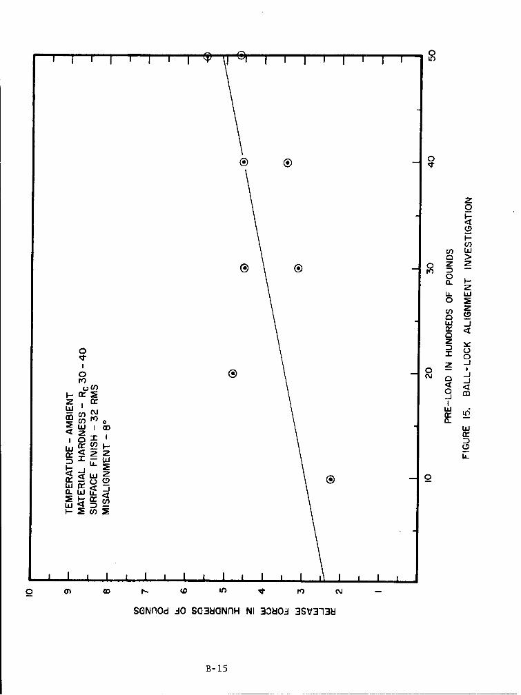
Angular misalignments of one, two, three, four, six and eight degreesin ball-lock and collet-lock test set-ups were investigated. A misalignmentgreater than eight degrees cannot be tested as that is the largest angle atwhich the two halves of the lock may be coupled together. In the ball-locktests, the resulting release forces increased in direct proportion with thedegree of misalignment. Although release forces above 550 pounds occurred inthe six-degree tests,.no failures to release occurred. In the collet-lock tests,however, no pattern was detected in the comparison of the results, and the releaseforces in general were lower than those obtained in the ball-lock tests. Onecollet, however, fractured during the six-degree tests.
2.5 LIFE CYCLE INVESTIGATION
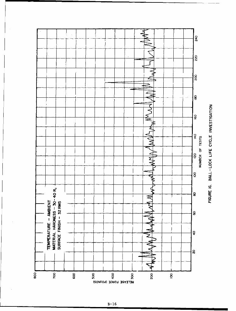
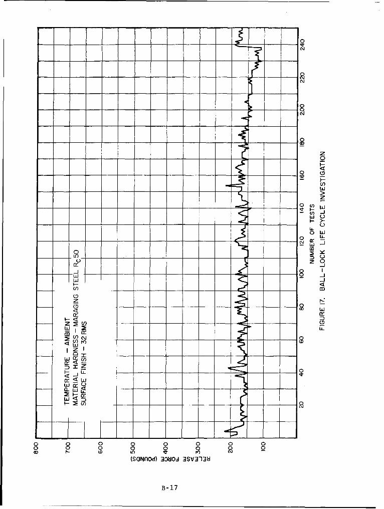
Two life cycle test series of 250 tests each were performed on bothball-lock and collet-lock configurations. In the ball-lock tests, the two serieswere performed with hardware of two hardnesses, Rc 35 and Rc 50. When compared,the Rc 50 tests resulted in generally lower release forces and less data scatterthan did the Rc 35 tests. In one collet-lock test series, a fracture occurred ontest number 180. Another collet-lock, however, successfully completed 250 cycles.Lubrication was used in both collet-lock test series.
3.0 TEST HARDWARE
I.i GENERAL
The locking devices tested in this program were pneumatically releasedby means of a piston-cylinder arrangement with Buna-N "0" ring seals. Theeffective surface area of the piston was one square inch. Removable tips asshown in illustration 2, Appendix A, allowed the pneumatic cylinder to be usedin testing either the ball-lock or collet-lock configuration. System pre-loadswere applied hydraulically and measured with load cell instrumentation. Alltemperatures were measured and recorded with potentiometric recording equipment.With the exception of the lubrication study tests and some collet tests, nolubrication was used on the locking surfaces. Although various types oflubrication were used on the pneumatic cylinder depending on the temperature ofthe test environment no attempt will be made to evaluate the performance of thishardware.
3.2 BALL-LOCK
The ball-locks tested in this phase of the program were four-ballconfigurations with a ball retainer tip diameter of 1,810 inches. Of the threeball-lock sizes investigated in Phase I of the program, this size was selectedfor Phase II testing due to past experience with locks of this size. (Ref.illustrations land 2). A race angle of 70 degrees established in Phase I testingas optimum for ball-locks in this size range, was used exclusively in all Phase IItesting. (Ref. illustration 4). The ball-retainer was fabricated from 304stainless steel, condition B (hardness Rc 35), in accordance with SpecificationQQ-S-763. In all tests 440C stainless steel balls, full hard (Rc 58), were used.The materials for race and release pin fabrication were varied in order to achievevarious hardness conditions. These materials included 304 stainless steel, 17-4PHstainless steel, 18 per cent nickel maraging steel, and beryllium copper.
3.3 COLLET-LOCK
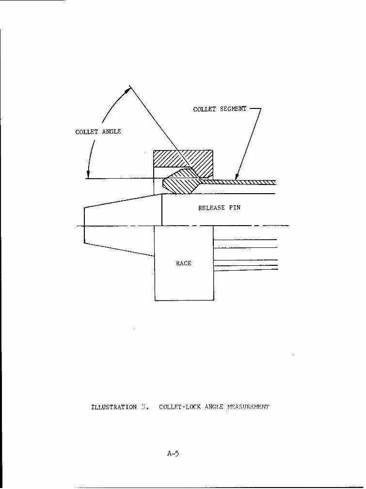
One-inch diameter collet-locks of a one-piece, twelve segment, cantileverconfiguration were selected for use in this phase of the program. This configurationis identical to that used in most of Phase I testing (Ref. illustration 3). Thecollet angle and race angle used in Phase II testing was 75 degrees. This wasthe angle value that was optimized in Phase I of the program (Ref. illustration 5).All collets were fabricated from beryllium copper in accordance with SpecificationQQ-C-530 and heat treated to an HT condition (hardness Rc 45). As in the caseof ball-lock hardware, the collet races and release pins were fabricated fromvaried materials which include 304 stainless steel, 17-4PH stainless steel,18 per cent nickel maraging steel, and beryllium copper. Lubrication of thecollet locking surfaces was performed in some sections of the program.
4.0 DISCUSSION
4.1 BALL-LOCK TESTING
4.1.1 Material Hardness Investigation
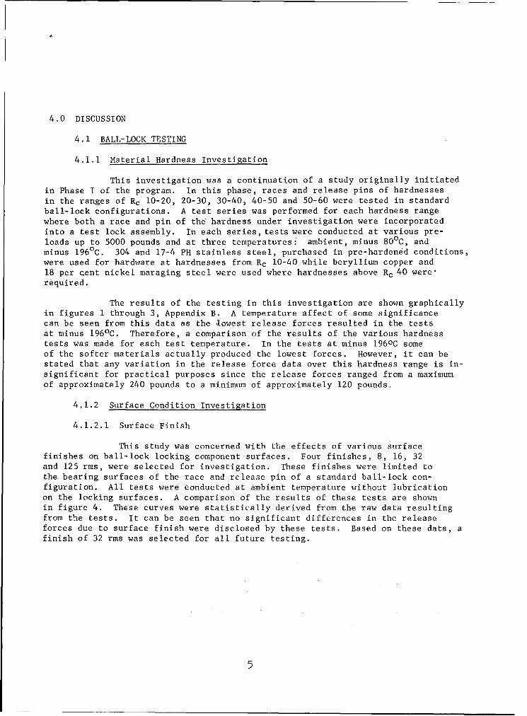
This investigation was a continuation of a study originally initiatedin Phase I of the program. In this phase, races and release pins of hardnessesin the ranges of Rc 10-20, 20-30, 30-40, 40-50 and 50-60 were tested in standardball-lock configurations. A test series was performed for each hardness rangewhere both a race and pin of the hardness under investigation were incorporatedinto a test lock assembly. In each series, tests were conducted at various pre-loads up to 5000 pounds and at three temperatures: ambient, minus 80 0 C, andminus 196 0 C. 304 and 17-4 PH stainless steel, purchased in pre-harden6d conditions,were used for hardware at hardnesses from Rc 10-40 while beryllium copper and18 per cent nickel maraging steel were used where hardnesses above Rc 40 were-required.
The results of the testing in this investigation are shown graphicallyin figures I through 3, Appendix B. A temperature affect of some significancecan be seen from this data as the lowest release forces resulted in the testsat minus 196 0 C. Therefore, a comparison of the results of the various hardnesstests was made for each test temperature. In the tests at minus 1960C someof the softer materials actually produced the lowest forces. However, it can bestated that any variation in the release force data over this hardness range is in-significant for practical purposes since the release forces ranged from a maximumof approximately 240 pounds to a minimum of approximately 120 pounds.
4.1.2 Surface Condition Investigation
4.1.2.1 Surface Finish
This study was concerned with the effects of various surfacefinishes on ball-lock locking component surfaces. Four finishes, 8, 16, 32and 125 rms, were selected for investigation. These finishes were limited tothe bearing surfaces of the race and release pin of a standard ball-lock con-figuration. All tests were conducted at ambient temperature without lubricationon the locking surfaces. A comparison of the results of these tests are shownin figure 4. These curves were statistically derived from the raw data resultingfrom the tests. It can be seen that no significant differences in the releaseforces due to surface finish were disclosed by these tests. Based on these data, afinish of 32 rms was selected for all future testing.
4.1.2.2 Lubrication
All tests in Phase I and II of this program prior to this series
were performed without the benefit of lubrication on the lock bearing surfaces.
This series of tests demonstrate the effects of lubrication. Five lubricants were
selected for their LOX compatibility and/or low temperature properties. Theselubricants were as follows:
1. Electrofilm Lubri-Bond A - A molybdenum disulfide spray
film - not compatible with LOX.
2. Molykote Z - A molybdenum disulfide dry powder - good
low temperature and LOX compatibility properties.
3. Fluorocarbon S-122 - A teflon spray film - good low
temperature and LOX compatibility properties.
4. Dow Corning FS1281 - A grease - good low temperatureproperties to minus 80 degrees Fahrenheit (OF) requires
batch testing to assure LOX compatibility.
5. KEL-F-#90 - A grease - LOX compatible - freezes at extremelylow temperatures.
These lubricants were applied to the bearing surfaces of the releasepin and race only. The results of this study are shown graphically in figures 5
through 7. Tests were conducted at three temperatures, ambient, minus 800C andminus 196 0 C, and a comparison of the data was made at each temperature. In
figure 5, a comparison at ambient temperature, it can be seen that no improvements
in release force resulted except where the film type lubricants were used. The
release forces occurring in the tests where the two greases were used were actually
higher than those occurring in tests where the system was unlubricated. However,
the data comparison at minus 196 0 C, figure 7, shows t1hat all lubricants improvedthe releasing characteristics of the lock although both the greases froze at that
temperature. In all cases the lowest release forces resulted in tests using the
Electrofilm Lubri-Bond A.
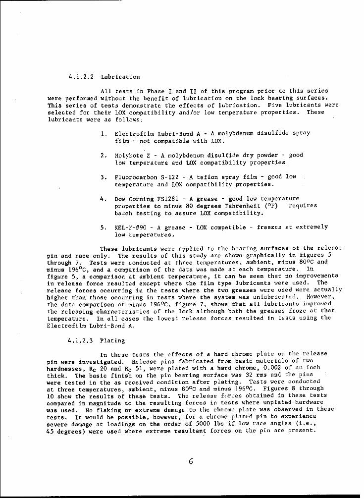
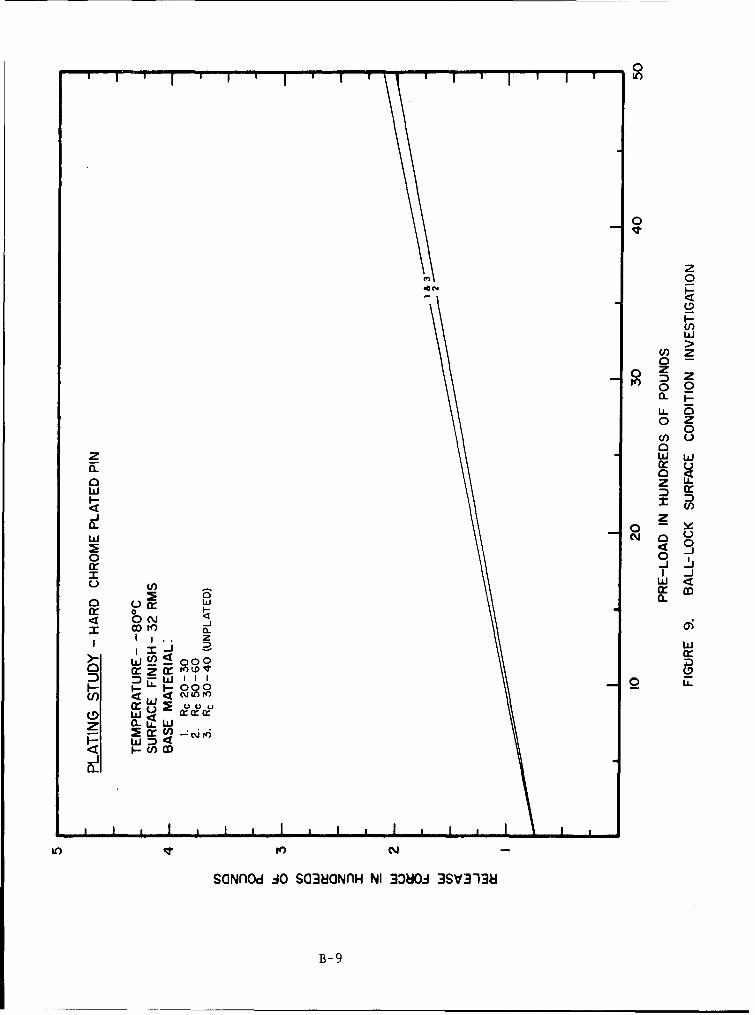
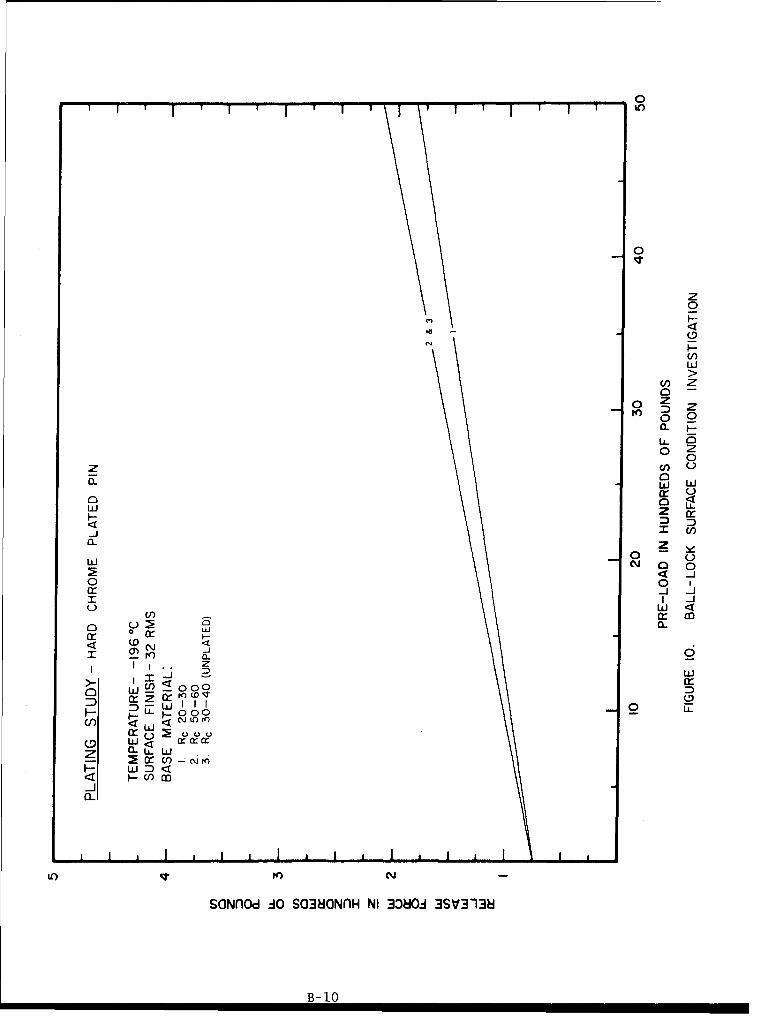
4.1.2.3 Plating
In these tests the effects of a hard chrome plate on the release
pin were investigated. Release pins fabricated from basic materials of two
hardnesses, Rc 20 and Rc 51, were plated with a hard chrome, 0.002 of an inch
thick. The basic finish on the pin bearing surface was 32 rms and the pins
were tested in the as received condition after plating. Tests were conducted
at three temperatures, ambient, minus 8 0 0C and minus 196 0 C. Figures 8 through
10 show the results of these tests. The release forces obtained in these tests
compared in magnitude to the resulting forces in tests where unplated hardware
was used. No flaking or extreme damage to the chrome plate was observed in these
tests. It would be possible, however, for a chrome plated pin to experience
severe damage at loadings on the order of 5000 lbs if low race angles (i.e.,
45 degrees) were used where extreme resultant forces on the pin are present.
6
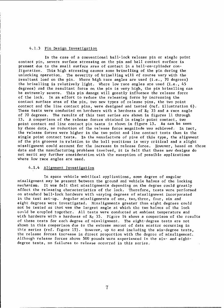
4.1.3 Pin Design Investigation
In the case of a conventional ball-lock release pin or single pointcontact pin, severe surface stressing on the pin and ball contact surface ispresent due to the small surface area of contact in a ball-on-cylinder con-figuration. This high stressing causes some brinelling of the pin during theunlocking operation. The severity of brinelling will of course vary with theresultant load on the pin. Where high race angles are used (i.e., 70 degrees)the brinelling is relatively light. Where low race angles are used (i.e., 45degrees) and the resultant force on the pin is very high, the pin brinelling canbe extremely severe. This pin damage will greatly influence the release forceof the lock. In an effort to reduce the releasing force by increasing thecontact surface area of the pin, two new types of release pins, the two pointcontact and the line contact pins, were designed and tested (ref. illustration 6).These tests were conducted on hardware with a hardness of'Rc 35 and a race angleof 70 degrees. The results of this test series are shown in figures 11 through13. A comparison of the release forces obtained in single point contact, twopoint contact and line contact pin tests is shown in figure 13. As can be seenby these data, no reduction of the release force magnitude was achieved. In tact,the release forces were higher in the two point and line contact tests than in thesingle point contact tests. In the manufacture of pins of this type, the alignmentof the pin grooves in relation to the ball positions is very critical and a slightmisalignment could account for the increase in release force. However, based on thesedata and the manufacturing problems involved, it is felt that these new designs donot merit any further consideration with the exception of possible applicationswhere low race angles are used.
4.1.4 Alignment Investigation
In space vehicle umbilical applications, some degree of angularmisalignment may be present between the ground and vehicle halves of the lockingmechanism. It was felt that misalignments depending on the degree could greatlyaffect the releasing characteristics of the lock. Therefore, tests were performedon standard ball-lock hardware with varying degrees of misalignment incorporatedin the test set-up. Angular misalignments of one, two, three, four, six andeight degrees were investigated. Misalignments greater than eight degrees couldnot be tested as that was the largest angle at which the two halves of the lockcould be coupled together. All tests were conducted at ambient temperature andwith hardware with a hardness of Rc 35. Figure 14 shows a comparison of the resultsof these tests for each degree of misalignment. The eight-degree tests are notshown in this comparison due to the extreme amount of data scatter occurring inthis series (ref. figure 15). However, up to and including the six-degree tests,the release forces increase in direct proportion with the degree of misalignment.Although release forces above 500 pounds were experienced in the six- and eight-degree tests, no failures to release occurred in this series.
4.1.5 Life Cycle Investigation
Life cycle test series were performed on ball-lock hardware withraces and release pins of two hardnesses, Rc 35 and Rc 50. Each configurationwas cycled at least 250 times at 5000 pounds pre-load. These tests were conductedat ambient temperature on conventional 70 degree ball-lock test assemblies. Afinish of 32 rms was used on the bearing surfaces in both cases. The resultsof these tests can be seen in figures 16 and 17. The Rc 50 tests resulted ingenerally lower release forces and less data scatter. No failures to releaseoccurred during either series.
4.2 COLLET-LOCK TESTING
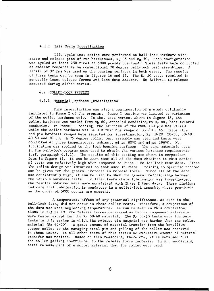
4.2.1 Material Hardness Investigation
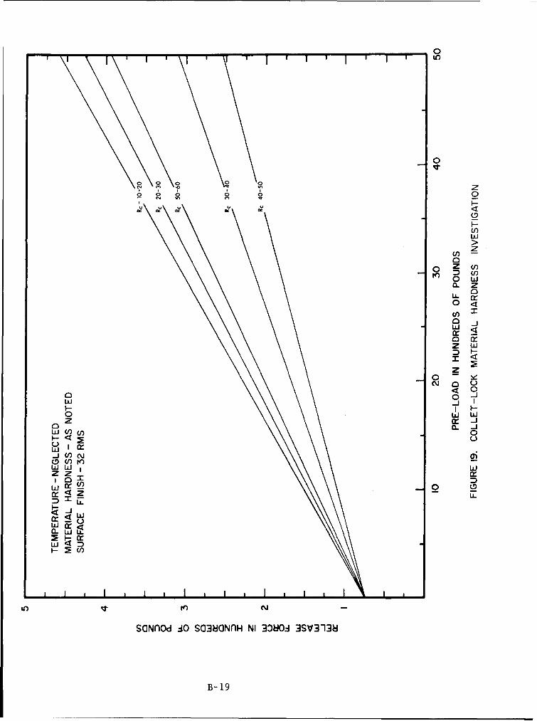
This investigation was also a continuation of a study originallyinitiated in Phase I of the program. Phase I testing was limited to variationof the collet hardness only. In that test series, shown in figure 18, thecollet hardness was varied from Rb 60, annealed condition, to Rc 44, heat treatedcondition. In Phase II testing, the hardness of the race and pin was variedwhile the collet hardness was held within the range of Rc 40 - 45. Five raceand pin hardness ranges were selected for investigation, Rc 10-20, 20-30, 30-40,40-50 and 50-60. A 75 degree collet test assembly was used and tests wereconducted at three temperatures, ambient, minus 80 0 C and minus 196 0 C. Nolubrication was applied to the lock bearing surfaces. The same materials usedin the ball-lock program were used to obtain the various hardness requirements(ref. paragraph 4.1.1). The results of this testing are shown in comparisonform in figure 19. It can be seen that all of the data obtained in this seriesof tests was relatively high when compared to Phase I collet-lock test data. Sincethe collet design was identical to that used in Phase I testing no specific reasonscan be given for the general increase in release force. Since all of the datawas consistantly high, it can be used to show the general relhtionship betweenthe various hardness tests. In later tests where lubrication was investigated,the results obtained were more consistant with Phase I test data. These findingsindicate that lubrication is mandatory in a collet-lock assembly where pre-loadson the order of 5000 pounds are present.
A temperature affect of any practical significance, as seen in theball-lock data, did not occur in these collet tests. Therefore, a comparison ofthe data was made neglecting temperature. As can be seen in this comparison,shown in figure 19, the release forces decreased as harder component materialswere tested except for the Rc 50-60 material. The Rc 50-60 tests were the onlytests in this series in which the release pin material was harder than the colletmaterial (Rc 40-50). A great amount of material transfer from the berylliumcopper collet to the maraging steel pin and galling of the collet was observedin these tests. In all other tests of this series no excessive amount of materialtransfer was noticed. Based on this reasoning, therefore, it is surmised thatthe collet galling contributed to the release force increase. In all succeedingtests release pins of a softer material than the collet were used.
8
4.2.2 Surface Condition Investigation
4.2.2.1 Surface Finish
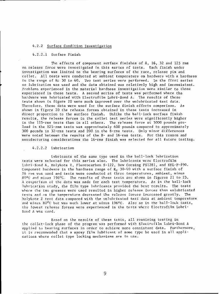
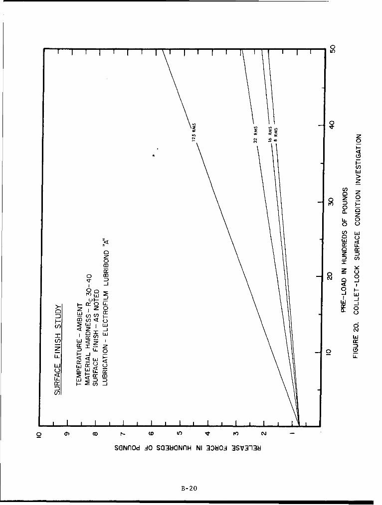
The effects of component surface finishes of 8, 16, 32 and 125 rmson release force were investigated in this series of tests. Each finish underinvestigation was limited to the bearing surfaces of the race, release pin andcollet. All tests were conducted at ambient temperature on hardware with a hardnessin the range of Rc 30 to 40. Two test series were performed. In the first seriesno lubrication was used and the data obtained was relatively high and inconsistant.Problems experienced in the material hardness investigation were similar to thoseexperienced in these tests. A second series of tests was performed where thehardware was lubricated with Electrofilm Lubri-Bond A. The results of thesetests shown in figure 20 were much improved over the unlubricated test data.Therefore, these data were used for the surface finish effects comparison. Asshown in figure 20 the release forces obtained in these tests increased indirect proportion to the surface finish. Unlike the ball-lock surface finishresults, the release forces in the collet test series were significantly higherin the 125-rms tests than in all others. The release force at 5000 pounds pre-load in the 125-rms tests was approximately 600 pounds compared to approximately300 pounds in 32-rms tests and 200 in the 8-rms tests. Only minor differenceswere noted between the results of the 8- and 16-rms tests. For this reason andmanufacturing considerations the 16-rms finish was selected for all future testing.
4.2.2.2 Lubrication
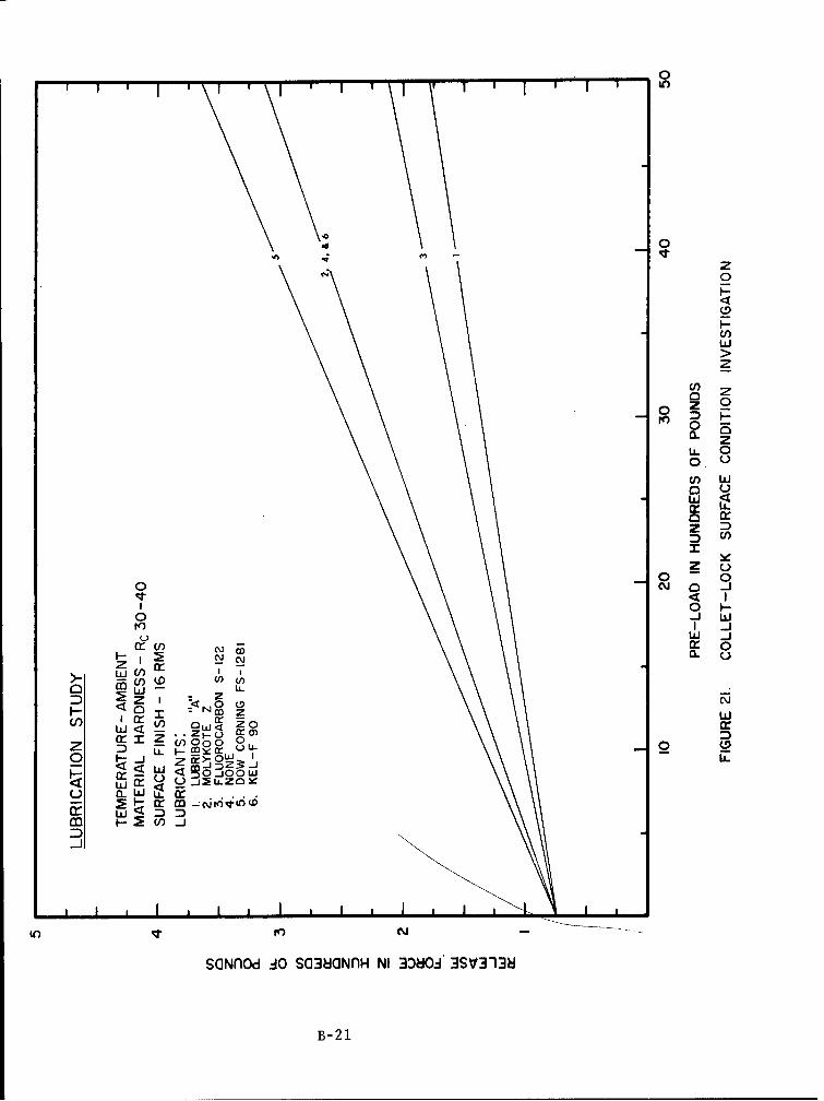
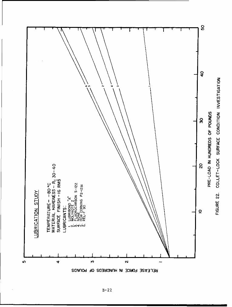
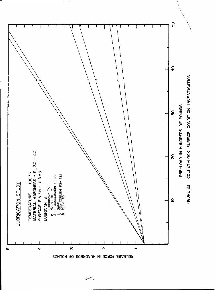
Lubricants of the same type used in the ball-lock lubricationtests were selected for this series also. The lubricants were ElectrofilmLubri-Bond A, Molykote Z, Fluorocarbon S-122, Dow Corning FS1281, and KEL-F-#90.Component hardware in the hardness range of Rc 30-40 with a surface finish of16 ruis was used and tests were conducted at three temperatures, ambient, minus80 0 C and miilus 196 0 C. The results of these tests are shown in figures 21 to 23.A comparison of the data was made for each test temperature. As in the ball-locklubrication study, the film type lubricants provided the best results. The testswhere the two greases were used resulted in higher release forces than unlubricatedtests and as the temperature decreased the release forces increased greatly. TheMolykote Z test data compared with the unlubricated test data at ambient temperatureand minus 80 0 C but was much lower at minus 196 0 C. Also as in the ball-lock tests,the lowest release forces were experienced in the tests where Electrofilm Lubri-Bon~d A was used.
Based on the results of these tests, all remaining testing inthe collet-lock phase of the program was performed with Electrofilm Lubri-Bond Aapplied to bearing surfaces in order to achieve more consistant data. Furthermore,it is recommended that a spray film lubticant of some type be used in all appli-cations where collet type locking mechanisms are in use.
9
4.2.2.3 Plating
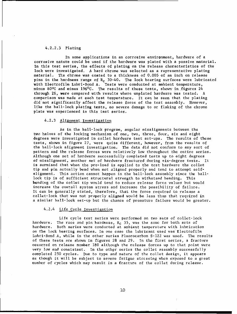
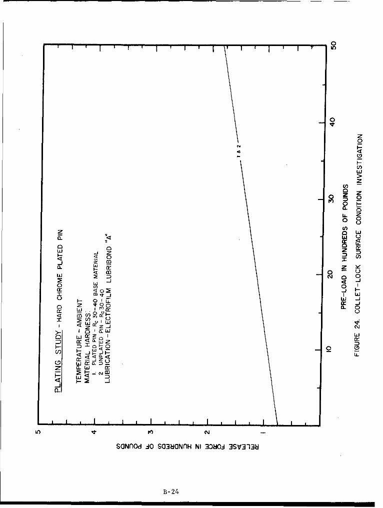
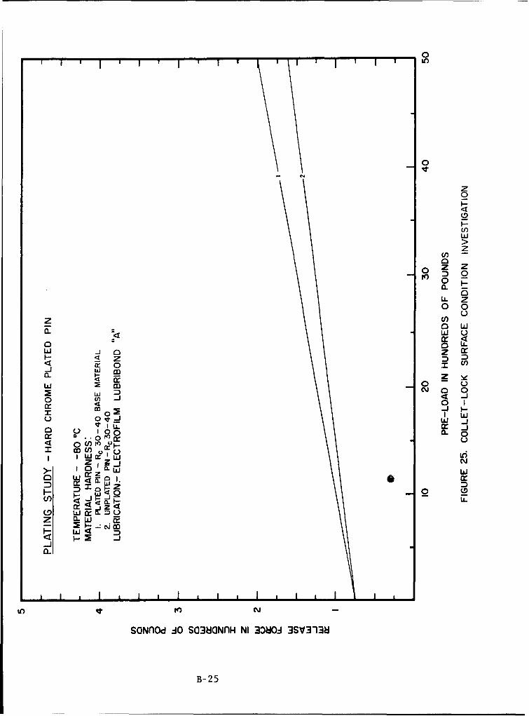
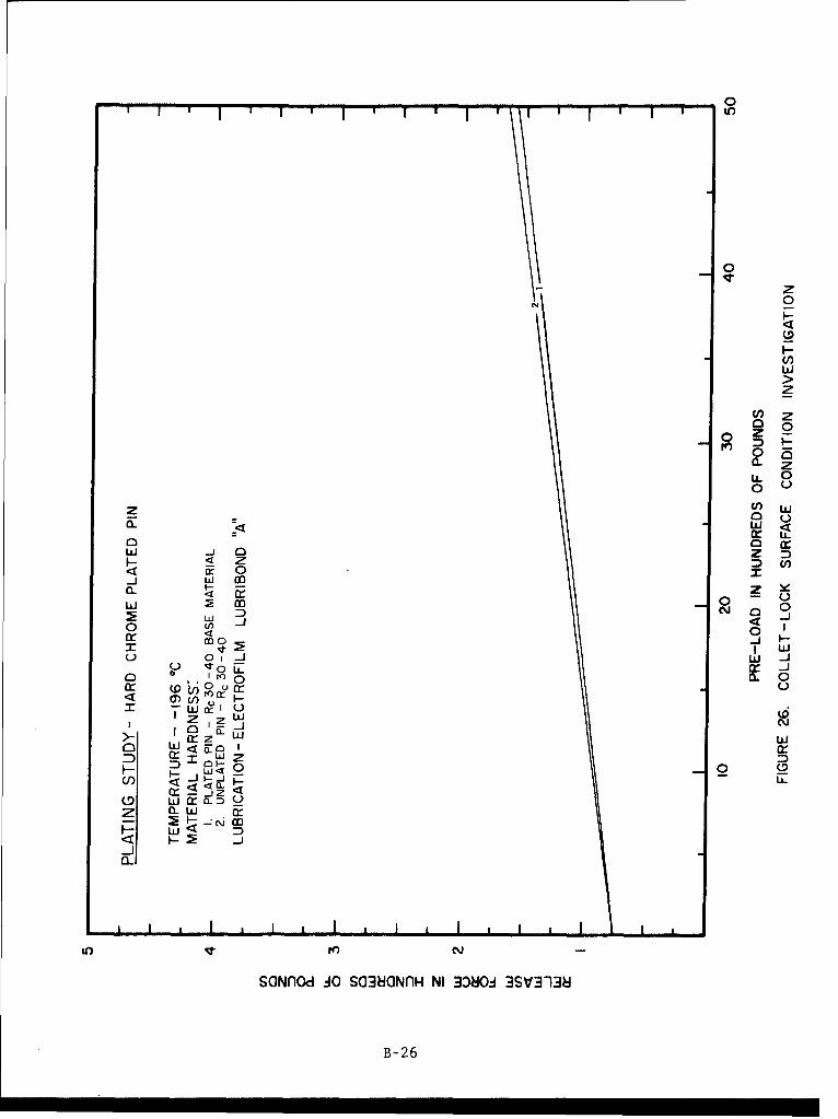
In some applications in an corrosive environment, hardware of acorrosive nature could be used if the hardware was plated with a passive material.In this test series, the effects of plating on the release characteristics of thelock were investigated. A hard chrome was selected as a representative platingmaterial. The chrome was coated to a thickness of 0.005 of an inch on releasepins in the hardness range of Rc 30-40. The lock bearing surfaces were lubricatedwith Electrofilm Lubri-Bond A. Tests were conducted at ambient temperature,minus 800C and minus 196 0 C. The results of these tests, shown in figures 24through 26, were compared with results where unplated hardware was tested. Acomparison was made at each test temperature. It can be seen that the platingdid not significantly affect the release force of the test assembly. However,like the ball-lock plating tests, no severe damage to or flaking of the chromeplate was experienced in this test series.
4.2.3 Alignment Investigation
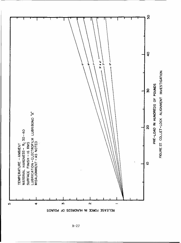
As in the ball-lock program, angular misalignments between thetwo halves of the locking mechanism of one, two, three, four, six and eightdegrees were investigated in collet hardware test set-ups. The results of thesetests, shown in figure 27, were quite different, however, from the results ofthe ball-lock alignment investigation. The data did not conform to any sort ofpattern and the release forces were relatively low throughout the entire series.Although one set of hardware successfully completed tests up to eight degreesof misalignment, another set of hardware fractured during six-degree tests. Itis surmised that when the pre-load is applied to the test hardware the collettip and pin actually bend when not aligned properly and tend to attempt self-alignment. This action cannot happen in the ball-lock assembly since the ball-lock tip is of sufficient structural strength to withstand bending. Thisbending of the collet tip would tend to reduce release force values but wouldincrease the overall system stress and increase the possibility of failure.It can be generally stated, therefore, that the force required to release acollet-lock that was not properly aligned would be less than that required ina similar ball-lock set-up but the chance of premature failure would be greater.
4.2.4 Life Cycle Investigation
Life cycle test series were performed on two sets of collet-lockhardware. The race and pin hardness, Rc 35, was the same for both sets ofhardware. Both series were conducted at ambient temperature with lubricationon the lock bearing surfaces. In one case the lubricant used was ElectrofilmLubri-Bond A, while in the other series Fluorocarbon S-122 was used. The resultsof these tests are shown in figures 28 and 29. In the first series, a fractureoccurred on release number 180 although the release forces up to that point werevery low and consistant. In the other series the collet assembly successfullycompleted 250 cycles. Due to type and nature of the collet design, it appearsas though it will be subject to severe fatigue stressing when exposed to a greatnumber of cycles which may result in a fracture of the collet during release.
i0
APPENDIX A
ILLUSTRATIONS
S~PNEUMATIC CYLINDER
•: •> •RACE
I
BALL RETAINE
PIN TIP
ILLUSTRATION 1. BALL-LOCK (2 INCH)
A-1
CnCH
O0
C;
0
-4
CZ)
A-2
PNEUMAT IC CYLINDER ,:
CLET ..
RELEASE PIN
ILLUSTRATION .i° COLLET-LOCK (1 INCH)
A-3
RACENGLE
S~BALL ,
'RELEASE PIN ••
BALL RETAINER
ILLUSTRATION BALL-LOCK RACE ANGLE MEASUREMENT
A-4
COLLET SEGMENT
COLLET ANGLE
-"-• RELEASE PIN
RACE
ILLUSTRATION COLLET-LOCK ANGLE MEASUREMENT
A-5
BALL
RELEASE PIN
0 0SINGLE POINT CONTACT TWO POINT CONTACT
a0
LINE CONTACT
ILLUSTRATION 6. BALL-LOCK PIN DESIGN
A-6
APPENDIX B
GRAPHS
0c
00
d z
0 0It I,
>
00 Cf)
(f)
a zw 0
0 0-3
00
0 -z I
w
z 0
wIwz
F- LL
cIZ
2r <F- cOw D
SONflOd J~O S038GNflH NI 300 3SVy3-13ý
B-1
z
a 0
210
zDA
0 0
0 J0 -Jz <
CA m
IO N
00
C/) 0
a~w L
Er Cfl
U.O 10 C14
SONflOd J0 S03NONr1H NI 3080A 3SV313H
B- 2
0I IC)
0
a~.
LL LIOQ0 4
D iiU) Z
z
-JIIN
z ILU) (1) C
0) roww
zcc z
if) 'af
SONflod J~O S038ONflH NI 33801 3SV3-138
B- 3
0
cIC,
N z
0
DzN0
0-I-
w
00
z4l 0
w -w0 W -W
z z cr <
zzcr~ x
w z (
0- w I
SO~no JOS3OnHN 30- S33
B-4-
0T I I IC
0
z0
U)Wo>
o zo0 Z
05z
w0: wa uz 4<
0 z
400 0 -JK) 2 I
z ir C\J OD Lh m
co U) 0)> U) )f
D 0 x~ 0zDCl) r (f N c Z
cr4 cr w ) Lo0 < - Z~r-Ow0
C2 w j2L
m) -ui
IfO K) N
SONflod .JO S038ONflH NI 3380O4 3SV3138
B- 5
0I kn
0
0
w
o9 z
00
w Wcr 0-04z
0 yN~0
0 40
o ý cu a.0I 7
in V4 - o)h~
:LJ La.
I a 1: NJ o
F-
A~ zIn tO w
SOz~ u O SG0NO NI30O)~S3
z 0ý 0-6
0I ')
(D
z0
I-Cf,
U, >
o za0 zU.. I0
z
Z 4)
0 y
0 04
CD N 00 CL 0
Z z0Sz 0 0JJ (D
o OOWUz i
x - U) CD- 7
0
az0
-- 0
0
woz
aa 0
00
ui L )
0 o0
W 004
0 0.4C ca: W ix
M N F--
I m - c
>- -ww~
o -os
-Jl
if)/ N D
SONlod :10 SG38GNnH NI 3:D8Oz 3SV3'13U
B-8
00
EL
(nz
a.02
w~0:
w L
0 0~IrI
w <L) () W CD0 a C
cr 0
x OD e
=)W
LiJ W' 000
cr Cf)
Uw :) <
SGNflod :10 S03JNarnH NI 338O0A 3SV3138
B- 9
0I f I I 1 1
0
0
0
:) Z
CL
0~0
z~ Zn0-- H
C-)LLJ~ Z Z
zz y)0 L
0n 0
0 (0 LL0
-i-
o o 0Lc
I Lu
o l U) -00- n: I I
10 N/ -i
SONflod J~O S03HONflH NI 330804 3SV3138i
B-10
0
0
00
Z Z
0 cia.z
z0
a. az
ML -
0 x 0.z
rf) < 0CL Cl)0 -J
U22
w jrN 0r-Ii2
(f) z Iw *-j
<j W lz Cj (
w 42cr.
o O-WLL
w4
U)
SONnod AO S03uaNnH NI ~3080 3SV3"13
B-li1
0
z
z
z z0
0tot
LLo Z
o "'
w Z
0 Z u~
<i 0 -1
I U)I
I r- z INrIo- coUL4 2 w
z zo 4 zwCD
o D X LL L
OCWL w
w D
to I-~C
SONlod :jo Sa38aNflH NI 33804 3SV3'138J
B- 12
0
z
0
2 U 0C- U
I-0
w zS -~ 0zz
0~
0(0 N)
0
wz
z a:
0 z a.
0) Noc
oj X' (9
z -
(n 0W L
z
to) N-
SONflod JO S03HONflH NI 3080O1 3SV3T138
B- 13
z0
I-C!,
w
Lz >Dw0 Z
LLJ04w
z
D ym0
z-
0 N 0 00
0 _
,\J Z (D
Wcr4 0
4w~
0 Fr ~ (-) S2) N
SONflOd .JO S038ONI1H NI 308O.ý 3SV3'13
B- 14
0
zt
0
0C',
0>
z _2
00
0
0~ cl
crow I
0 ID It) N
SOOz cOS3GfHN 3r. S~J
a 3:B1 D
z
___ w
zz0w
I-
w cr 0
LLJ
ir- w. _ -
0 0 0 0 0 00 0 0 0
(SaNAOd) 3080J 3SV3-138
B- 16
0
z
I z
I~wO
ow
0 _ rLm
Ul)0z0 < Lu
WU) r
c'w
0 ~~0 0 00
0m 0 00!D It) E:
(Scfod <DiO wS3
W X-C7

00
ciE-44
ridM,
samm jo aawam mi3owaasImB-1
0
o 0 0 0 0,U) m v0
o 0 0 0
(I)
00 Zn
o w0
o _j
Z Lu
z0
Lu 00 -J
0 W~ Luz W -0 a.. .-
CD C/) PO
w cr? D (D
X LL
J-u .
SONflod J~O S03HGNr1H NI 3080A 3SV3-138
B- 19
zcq 0
It-
wz
Z 0
zU.~ 0o u-
a 0
ocrZ :D
0 U,
o mNr 0
0~j f 0 .
o ~0 jrn -J w
W ji
W- I
cr ')
zr Z 0
wo LJU
CO2<U)-
0~~~ CDI)r(
SOclr wOS~~l I3~. S33
W W <-20
0
.6 0
0
U-00 U)cn w
00iU) D
0 0
0
0 2wu w0 _j
cr ) cr 0
Cl)j
LL U) 4ojo
C.. (f)W(.w U-
LI) aw) N
w ~ ~ ~ ~ B 21 -(. r0
0
0 L
z
0
0 U))
00
zzF- 0 z N0
C/) w ( U) Ct w
U-~~~~ LPLWUL-Z~~ cc-oL
z Li
0r 04 n
to~
SOlno w0 S0H~HN 08- S33
B-220
0
z:D 0
I-
05
0
C,,
z
0 Z ~Nl 00
0 0Ile) _
I W
W J
U) 0LJ U)
0 _-
Z 0 (D 0 .liZQa aCwuz
F- 0: o) (r
L-J-JOL
2 ~ ~ ~ B 23r o i
0T tl
0
z0
CYO
wz
0 I
00
z U,
z owa- ~w (-
0 L<
0r co
w Fr Zw 0
0 -JUl) 0
C0 0 E -J
0 z~i I 0C r -
Ir LLt I O ( '4
0 L 0iCQD) cr r LC/) I
I <z
0~0
U) w N
SONflod JO S038ONflH NI 300 3SV3-138
B- 24
01 k,
0
z
0
wU,
L<J
z :z
LLI7 mL )2 00
00
I on
cr~~ 0U..or
z zi CILW
w 00-
a uj i
CB-2
01 J i l lI f- t,
0
zN 0
wz
o Z00a.J .
0L 0
w Z wI0 0
w. Z =)
0 -w
0 Cf0I<
roqt r- I W
L) ~ 0 1 _j D
z I Z
u)EC IN
D B- 26
01 ',
0
z0
CfD
(0Z
z Z0.~
o Zwa zw (Dz
zo z0
a:~~ Cj0 in
0~j 1 0ro W U
jw cc ir Z. U-
z 0 ý
W ~I w(
w cr L/ I~
ujFrU00,
M;!jcr co
IL) t-)
SONflod 30 S038ONflH NI 3080-4 3SV3-138
B- 27
U.
40
ww
La>
0z
4w
- - - - U)
_ 2I-
- - -- - -U.
-- ~ LL
z
0 -LJ__ o 0
___ 0
IT-
0 0
o w
~zI
F-ro
0 0 0 0 0 0 0 00 0 0 0 0 0 0, 0"OD t-fw IT t N-
%O~nd) 380A SV3138
B- 28
0
___ 0-- N
N
0
fo 0
0 0
z0 w
L) 0
10OD~ C.)
-A 0) (Wco W 1 40 U_
C.) 0
I OX
w
-0 0_ -0 0 0j
0 00 0 0 0 0 0OD1- 10 CN
NASA-Langley, 1968 - 31 B-29