Embed Size (px)
DESCRIPTION
Guideline for development standards
Citation preview

City of Sumner Development Specifications and Standard Details
March 2011

City of Sumner Table of Contents Development Specifications and Standard Details i March 2011
TABLE OF CONTENTS
1. GENERAL CONDITIONS AND REQUIREMENTS ......................................................................... 1-1 1.1 GENERAL .......................................................................................................................... 1-1 1.2 SCOPE OF WORK ............................................................................................................. 1-1
1.2.1 General ................................................................................................................... 1-1 1.2.2 Responsibility of Owner/Developer/Contractor ..................................................... 1-1 1.2.3 Additional Instructions or Changes ........................................................................ 1-1
1.3 CONTROL OF WORK ....................................................................................................... 1-2 1.3.1 General ................................................................................................................... 1-2 1.3.2 Authority of the Public Works Department ........................................................... 1-2 1.3.3 Cooperation by Contractor/Developer ................................................................... 1-2 1.3.4 Conformity with Plans and Specifications ............................................................. 1-2 1.3.5 Removal of Defective or Unauthorized Work ....................................................... 1-3 1.3.6 Protection of Public and Private Utilities ............................................................... 1-3 1.3.7 Damage to Private Property and Improvements ..................................................... 1-3 1.3.8 Hold Harmless Clause ............................................................................................ 1-3 1.3.9 Developer’s Contractor’s Public Liability and Property Damage Insurance ......... 1-4 1.3.10 Guarantees .............................................................................................................. 1-4 1.3.11 Stormwater Maintenance Agreement ..................................................................... 1-5 1.3.12 Final Inspection ...................................................................................................... 1-5 1.3.13 Final Acceptance .................................................................................................... 1-5 1.3.14 Maintenance of Work After Acceptance ................................................................ 1-7
1.4 CONTROL OF MATERIALS ............................................................................................ 1-7 1.4.1 General ................................................................................................................... 1-7 1.4.2 Source of Supply and Quality of Materials ............................................................ 1-7 1.4.3 Materials Inspection and Testing ........................................................................... 1-7 1.4.4 Storage of Materials ............................................................................................... 1-8 1.4.5 Defective Materials ................................................................................................ 1-8
1.5 DESIGN PLANS AND SPECIFICATIONS ...................................................................... 1-8 1.5.1 Content of Final Engineering Plans ....................................................................... 1-8 1.5.2 Approved Plan Submittal Requirements .............................................................. 1-11
1.6 GENERAL PLAN NOTES ............................................................................................... 1-11
2. STANDARDS FOR TESC ................................................................................................................ 2-1 2.1 GENERAL .......................................................................................................................... 2-1 2.2 STANDARD SPECIFICATIONS ...................................................................................... 2-1 2.3 TESC DESIGN REQUIREMENTS .................................................................................... 2-1
2.3.1 Construction SWPPP Requirements ...................................................................... 2-1 2.3.2 TESC Design Standards ......................................................................................... 2-2
2.4 TESC MAINTENANCE REQUIREMENTS ..................................................................... 2-3

TABLE OF CONTENTS (Continued)
City of Sumner Table of Contents Development Specifications and Standard Details ii March 2011
2.5 INSPECTION ..................................................................................................................... 2-3 2.6 WET SEASON REQUIREMENTS .................................................................................... 2-4 2.7 SENSITIVE AREA REQUIREMENTS ............................................................................. 2-4 2.8 NPDES PERMIT REQUIREMENTS ................................................................................. 2-4 2.9 STORMWATER SITE PLAN TESC NOTES ................................................................... 2-4
3. STANDARDS FOR WATER SYSTEM IMPROVEMENTS .............................................................. 3-1 3.1 GENERAL .......................................................................................................................... 3-1 3.2 STANDARD SPECIFICATIONS ...................................................................................... 3-1 3.3 WATER MAIN EXTENSION DESIGN REQUIREMENTS ............................................ 3-1
3.3.1 General ................................................................................................................... 3-1 3.3.2 Water Plan Requirements ....................................................................................... 3-2 3.3.3 Sumner Water System Plan .................................................................................... 3-3 3.3.4 Sumner Water System Design ................................................................................ 3-3 3.3.5 Water System Components .................................................................................... 3-5
3.4 WATER SYSTEM COMPONENTS MATERIALS AND INSTALLATION .................. 3-8 3.4.1 Water Service Laterals ........................................................................................... 3-8 3.4.2 Water Meter Assembly........................................................................................... 3-9 3.4.3 Water Main and Appurtenances ........................................................................... 3-10
3.5 CROSS CONNECTIONS ................................................................................................. 3-12 3.5.1 Backflow Prevention ............................................................................................ 3-13 3.5.2 Residential Irrigation System ............................................................................... 3-14
3.6 TESTING REQUIREMENTS .......................................................................................... 3-15 3.6.1 Pressure and Leakage Tests .................................................................................. 3-15 3.6.2 Flushing ................................................................................................................ 3-15 3.6.3 Purity Testing ....................................................................................................... 3-16 3.6.4 Connection to Existing Water System ................................................................. 3-16
4. STANDARDS FOR SANITARY SEWER SYSTEMS ...................................................................... 4-1 4.1 GENERAL .......................................................................................................................... 4-1 4.2 STANDARD SPECIFICATIONS ...................................................................................... 4-1 4.3 SEWER MAIN EXTENSION DESIGN REQUIREMENTS ............................................. 4-1
4.3.1 General ................................................................................................................... 4-1 4.3.2 Sewer Plan Requirements....................................................................................... 4-2 4.3.3 City of Sumner Sanitary Sewer Comprehensive Plan ............................................ 4-2 4.3.4 Sumner Sewer System Design ............................................................................... 4-3 4.3.5 Gravity Sewer System Components ....................................................................... 4-5
4.4 SEWER SYSTEM COMPONENTS, MATERIALS, AND INSTALLATION ................. 4-6 4.4.1 Gravity Sewer Main and Appurtenances ............................................................... 4-6

TABLE OF CONTENTS (Continued)
City of Sumner Table of Contents Development Specifications and Standard Details iii March 2011
4.5 WASTE DISCHARGE ....................................................................................................... 4-9 4.5.1 Oil/Water Separators .............................................................................................. 4-9 4.5.2 Grease Interceptors ............................................................................................... 4-10
4.6 TESTING REQUIREMENTS .......................................................................................... 4-11 4.6.1 Cleaning ............................................................................................................... 4-11 4.6.2 Deflection Testing ................................................................................................ 4-11 4.6.3 Leakage Testing ................................................................................................... 4-11 4.6.4 Television Inspection ........................................................................................... 4-12 4.6.5 Alternate Sewer Systems ...................................................................................... 4-13 4.6.6 Recommended Alternate Sewer Systems ............................................................. 4-14 4.6.7 Alternative Sewer System Appurtenances ........................................................... 4-15 4.6.8 Testing Requirements ........................................................................................... 4-24
5. STANDARDS FOR STORMWATER SYSTEM IMPROVEMENTS ................................................. 5-1 5.1 GENERAL .......................................................................................................................... 5-1 5.2 STANDARD SPECIFICATIONS ...................................................................................... 5-2 5.3 STORMWATER SYSTEM DESIGN REQUIREMENTS ................................................. 5-2
5.3.1 General ................................................................................................................... 5-2 5.3.2 Stormwater Site Plan Requirements ....................................................................... 5-4 5.3.3 Pollution Source Control Program ......................................................................... 5-6 5.3.4 Thresholds .............................................................................................................. 5-7 5.3.5 City of Sumner Stormwater Comprehensive Plan ............................................... 5-11 5.3.6 Sumner Stormwater System Design ..................................................................... 5-11 5.3.7 Stormwater System Components ......................................................................... 5-15
5.4 STORM SYSTEM COMPONENTS MATERIALS AND INSTALLATION ................. 5-20 5.4.1 Stormwater Conveyance ...................................................................................... 5-20 5.4.2 Catch Basins ......................................................................................................... 5-22 5.4.3 Stormwater Laterals ............................................................................................. 5-23
5.5 TESTING REQUIREMENTS .......................................................................................... 5-23 5.5.1 Cleaning ............................................................................................................... 5-23 5.5.2 Leakage Testing ................................................................................................... 5-23 5.5.3 Television Inspection ........................................................................................... 5-24
5.6 MAINTENANCE RESPONSIBILITIES.......................................................................... 5-24 5.6.1 Maintenance Agreement ...................................................................................... 5-25 5.6.2 Maintenance Responsibility ................................................................................. 5-25 5.6.3 Single-family Residential: Short or Full Subdivision .......................................... 5-26 5.6.4 Commercial/Industrial/Multifamily ..................................................................... 5-28
5.7 STORMWATER CONSTRUCTION INSPECTION SCHEDULE AND REPORTS ..... 5-29 5.7.1 Inspection Schedule and Reports ......................................................................... 5-29 5.7.2 Inspection Requirements during Construction ..................................................... 5-29

TABLE OF CONTENTS (Continued)
City of Sumner Table of Contents Development Specifications and Standard Details iv March 2011
5.7.3 Final Inspection .................................................................................................... 5-31 5.7.4 Inspections Following Project Acceptance .......................................................... 5-31
5.8 STORMWATER SITE PLAN NOTES ............................................................................ 5-31
6. ROADWAY, TRAFFIC SIGNALS, AND ILLUMINATION ............................................................... 6-1 6.1 ROADWAY STANDARDS ............................................................................................... 6-1
6.1.1 General ................................................................................................................... 6-1 6.1.2 Standard Specifications .......................................................................................... 6-1 6.1.3 Design Requirements ............................................................................................. 6-1 6.1.4 City of Sumner Transportation Plan ....................................................................... 6-2 6.1.5 Roadway Design .................................................................................................... 6-2 6.1.6 Roadway Materials and Construction .................................................................. 6-10 6.1.7 Testing Requirements ........................................................................................... 6-15
6.2 TRAFFIC SIGNAL SYSTEMS ........................................................................................ 6-17 6.2.1 General ................................................................................................................. 6-17 6.2.2 Standards .............................................................................................................. 6-17 6.2.3 Design Requirements ........................................................................................... 6-18 6.2.4 Installation Requirements ..................................................................................... 6-21 6.2.5 Material Requirements ......................................................................................... 6-29
6.3 ILLUMINATION SYSTEMS ........................................................................................... 6-34 6.3.1 General ................................................................................................................. 6-34 6.3.2 Standards .............................................................................................................. 6-35 6.3.3 Design Requirements ........................................................................................... 6-35 6.3.4 Installation Requirements ..................................................................................... 6-38 6.3.5 Material Requirements ......................................................................................... 6-39
LIST OF TABLES
3-1 Health Hazard Classification ................................................................................................... 3-13
3-2 Approximate Flow Required for Water Main Flushing ........................................................... 3-15
4-1 Sanitary Sewer Pipe Allowable Ponding ................................................................................. 4-12
6-1 City of Sumner – Minimum Site Distance Requirements .......................................................... 6-7
6-2 Light Level and Uniformity Ratio ........................................................................................... 6-37
6-3 Initial Lumen Values ................................................................................................................ 6-37

TABLE OF CONTENTS (Continued)
City of Sumner Table of Contents Development Specifications and Standard Details v March 2011
APPENDICES
A Record Drawing Preparation and Submittal Requirements
B Stormwater Agreements
C Preconstruction Bonding Forms
D Post-Construction Bonding Forms
E Final Cost Data, Inventory Forms, and Bill of Sale
F Rainfall Intensity Graph
G Single Family Residential Infiltration System Design Guide
H Sewer Agreement
I Sumner Standard Notes and Details

City of Sumner Acronyms Development Specifications and Standard Details vi March 2011
ACRONYMS
AASHTO American Association of State Highway and Transportation Officials
AADT Annual Average Daily Traffic
ADA Americans with Disabilities Act
ADT average daily traffic
AG air gap
BMPs Best Management Practices
CABO Council of American Building Officials
City City of Sumner
DCDA double check detector assembly
DCVA double check valve backflow prevention assembly
DI ductile iron
DIPRA Ductile Iron Pipe Research Association
DNR Department of Natural Resources
DOE Washington State Department of Ecology
ESD entering sight distance
FOG Fats, Oils, and Grease
fps feet per second
GI galvanized iron
GSP General Special Provision
HDPE high density polyethylene
HPA Hydraulic Project Approval
IAMPO International Association of Plumbing and Mechanical Officials
ID inside diameter
IPS iron pipe size

ACRONYMS (Continued)
City of Sumner Acronyms Development Specifications and Standard Details vii March 2011
LID Low Impact Development
LOS level-of-service
Manual Stormwater Management Manual for Western Washington
MID Maximum Instantaneous Demand
MJ mechanical joint
NAD North American Datum
NEC National Electric Code
NGVD national geodetic vertical datum
NSF National Sanitary Foundation
NST National Standard Thread
PC point of curvature
PGIS pollution generating impervious surfaces
PGPS pollution generating pervious surfaces
PHD Peak Hour Demand
psi pounds per square inch
PSP/PSAT Puget Sound Partnership/Puget Sound Action Team
PT point of tangency
PVC polyvinyl chloride
RPBA reduced pressure principal backflow prevention assembly
RPDA reduced pressure principal detector backflow prevention assembly
SBR styrene-butadiene rubber
SD Special Design
SDG Small Diameter Gravity System
SDR standard dimension ratio
SMC Sumner Municipal Code

ACRONYMS (Continued)
City of Sumner Acronyms Development Specifications and Standard Details viii March 2011
SMMWW Stormwater Management Manual for Western Washington
SMSDM Stormwater Management and Site Development Manual
SSD stopping sight distance
SSD Stopping Sight Distance
STEP Septic Tank Effluent Pump System
SWPP Stormwater Pollution Prevention
SWPPP Stormwater Pollution Prevention Plan
TDH total dynamic head
TESC Temporary Erosion and Sedimentation Control
TMDL Total Maximum Daily Load
WB wheelbase
WSDOH Washington State Department of Health
WSDOT Washington State Department of Transportation
WSU Washington State University


City of Sumner Chapter 1 Development Specifications and Standard Details 1-2 March 2011
Such additional instructions and plans shall be consistent with the contract documents and, once approved by the City Engineer or designee, shall have the same force and effect as if contained in the original contract documents.
1.3 CONTROL OF WORK
1.3.1 General
The requirements outlined in WSDOT Specification Section 1-05 apply except that “Engineer” shall be replaced by “City Engineer or designee,” “Public Works Department.”
1.3.2 Authority of the Public Works Department
It is understood and agreed by and between the parties that the work included in the approved plans shall be completed to the satisfaction of the City Engineer or designee. All decisions made by the City Engineer or designee in relation to the true meaning of the plans, specifications, and estimates, and as to all questions arising as to proper performance of the work, shall be final.
The City Engineer or designee shall decide any and all questions that may arise as to the quality or acceptability of materials furnished and work performed, and as to the rate of progress of the work. Questions concerning acceptable fulfillment and performance of the improvements on the part of the Owner/Developer shall be answered by the City Engineer or designee.
1.3.3 Cooperation by Contractor/Developer
A set of approved plans, specifications, permits, and any special provisions and authorized alterations shall be on the job site at all times. The Developer or his/her duly authorized representative shall be at the job site continually during progress of the job. The Developer shall request explanations or design clarification as necessary from the Engineer of Record to allow the satisfactory performance and completion of the work. The Developer shall not cause any unnecessary delay or hindrance to other contractors on adjacent work, but shall be required to cooperate with other contractors to the fullest extent.
1.3.4 Conformity with Plans and Specifications
The City Engineer or designee shall have final say in all deviations from the plans prior to implementation.
The work shall be done in strict conformity with the approved plans and specifications and according to such necessary instructions as may be given by the City Engineer or designee. The Contractor shall protect and preserve, in the original position, all survey stakes, points, or marks set for the work in order to allow proper inspection. The Developer shall provide the City Engineer or designee with a complete set of survey cut sheets for all aspects of the infrastructure being improved or constructed.
Any change required to the approved plans shall be prepared by the Engineer of Record and submitted to the City Engineer or designee for review and approval. Work not in conformance with the approved plans shall be removed and installed per Plan as required by and to the satisfaction of the City Engineer or designee.

City of Sumner Chapter 1 Development Specifications and Standard Details 1-3 March 2011
1.3.5 Removal of Defective or Unauthorized Work
The City Engineer or designee may condemn defective work or materials any time before the final acceptance of the work. Such condemned work shall be immediately removed or disposed of to the satisfaction of the City Engineer or designee. Failure or neglect on the part of the Public Works Department to condemn unsatisfactory material or reject inferior workmanship will in no way release the Developer from needing to complete the work per the approved plans, nor shall it be construed to mean the acceptance of such work. Nor shall the final acceptance bar the City from recovering damages in case of fraud or defective work resulting from dishonesty.
The City will not accept unauthorized or defective work, including, but not limited to, work and materials that do not conform to these Development Specifications and Standard Details, work done beyond the approved plans or project scope, and extra work or materials furnished without written approval from the City Engineer or designee. The Contractor shall be responsible for all monies, materials, labor, and equipment required to remove and/or repair defective or unauthorized work to the satisfaction of the City Engineer or designee.
1.3.6 Protection of Public and Private Utilities
The Contractor shall be responsible for locating all existing underground utilities and protecting the same against damage. The Contractor shall support and protect all pipes, curbs, conduits, poles, wires, or other apparatus, which may be in any way affected by the work. Existing public or private utilities damaged during completion of the work shall be repaired by the Contractor prior to final project acceptance by the City. The Contractor shall be responsible for repairing all damaged utilities to the satisfaction of the Public Works Department.
The City is authorized to hire an outside contractor to complete the repairs, or complete the repairs itself, if the Contractor is unqualified or unable to complete the required work in a timely manner. The Contractor shall be responsible for all monies, materials, labor, and equipment required to complete such repairs.
1.3.7 Damage to Private Property and Improvements
The Contractor and/or Developer shall be responsible for the protection of private property in the vicinity of the project site. The Contractor’s work shall be confined to the clearing limits established on the approved plans and within the necessary off-site easements for which plans and specifications have been approved and permits issued. The Contractor shall not enter upon or place any materials on private premises without the written consent of the property owner.
The Developer shall hold the City harmless from all suits and actions of any kind that might result from the use of private property. The Developer is responsible for obtaining any/and all necessary permits when using private property.
1.3.8 Hold Harmless Clause
The Developer shall indemnify and hold harmless the City and their agents and employees from and against all claims, damages, losses, and expenses, including attorney’s fees, arising out of or resulting from the performance of the work, and shall defend and pay the expense of defending any suit and will pay any judgment, provided that any such claim, damage, loss, or expense (1) is attributable to bodily injury, sickness, disease, or death, or to injury or destruction of tangible property (other than the work

itself), including the loss of use resulting therefrom, and (2) is caused in whole or in part by any negligent act or omission or by any other action giving rise to strict liability of the Developer, Contractor, any subcontractor, anyone directly or indirectly employed by any of them, or anyone for whose acts any of them may be liable, regardless of whether or not it is caused in part by a party indemnified hereunder.
In any and all claims against the City, or any of their agents or employees, by any employee of the Developer, Contractor, any subcontractor, anyone directly or indirectly employed by any of them, or anyone for those acts any of them may be liable, the indemnification obligation under this article shall not be limited in any way by any limitation on the amount or type of damages, compensation, or under workman’s compensation acts, disability benefit acts, or other employee’s benefit acts.
1.3.9 Developer’s Contractor’s Public Liability and Property Damage Insurance
In addition to the required bonds, all permittees or their contractors shall be required to perform the following:
1. Present the City with a Certificate of Insurance. The Certificate shall be received by the City prior to permit issuance.
2. Submit a copy of the CG 20 12 endorsement naming the City of Sumner, its officers, and employees as additionally insured. The site address and the City Project/Permit Number shall be included in the description stated on the endorsement.
3. Maintain a Commercial General Liability insurance policy for the duration of the permit written with limits no less than $1,000,000 each occurrence, $2,000,000 general aggregate and a $2,000,000 products- completed operations aggregate limit. Applicant shall not reduce or cancel the policy without thirty (30) days written notice to the City.
1.3.10 Guarantees
All required performance bonding shall be in place prior to the start of construction. Private Developers or/Contractors completing work within the City of Sumner shall be prepared to satisfy the following bond requirements:
• Payment and Performance Bond (Capital Improvements)
• Performance Bond (Developer Improvements)
• Erosion and Sediment Control Bond
• Stormwater Facilities Bond
• Street Restoration Bond
• Stormwater Maintenance and Defect Bond
• Maintenance and Defect Bond
Sample bonding forms can be found in Appendices C and D.

City of Sumner Chapter 1 Development Specifications and Standard Details 1-5 March 2011
1.3.11 Stormwater Maintenance Agreement
Public Stormwater Control Facilities
Stormwater control facilities constructed by the Developer with the intent of conveying the facility to the City via a Bill of Sale are considered Public Stormwater Control Facilities. Developers of Public Stormwater Control Facilities shall be required to operate and maintain said facility for a period of two (2) years after Final Project Acceptance. Developer shall enter into an Agreement to Maintain Stormwater Facilities – Two (2) Year Warranty Period and Satisfactory Maintenance (see Appendix B) prior to permit issuance.
Private Stormwater Control Facilities
Stormwater control facilities constructed by the Developer that will be owned, operated, and maintained by the owner of the property serviced by said facility are considered Private Stormwater Control Facilities. Developer shall enter into an Agreement to Maintain Stormwater Facilities and to Implement a Pollution Source Control Plan (Appendix B) prior to project permit issuance. This agreement shall be recorded with Pierce County and shall be attached to and run with the property serviced by the Private Stormwater Control Facility for perpetuity.
1.3.12 Final Inspection
The City has the right to conduct inspections to determine whether acceptable construction practices are followed. The inspection process does not make the City responsible for any failures to follow these specifications. The Owner/Developer/Contractor shall be responsible for conformance with the approved plans and all applicable federal, state, county, and City requirements.
The Owner/Developer/Contractor shall notify the Public Works Department upon completion of the work and shall certify that all construction items have been completed per the approved plans and are ready for final inspection. The scheduled inspection will not take place if the Inspector finds upon his/her arrival on site that all items have not been completed.
The City Engineer or designee may at any time require the Owner/Developer/Contractor to submit properly authenticated documents or other satisfactory proof of his/her compliance with the contract requirements. If the examination of the above-mentioned documents reveals any defects in the work, such defects will be repaired or replaced by the Owner/Developer/Contractor as stipulated by the City Engineer or designee before final acceptance. The cost of all such repairs and replacements shall be borne by the Developer/Contractor.
1.3.13 Final Acceptance
Project improvements shall be considered ready for acceptance following the correction of any and all defects as noted on the final inspection.
Final acceptance of improvements requires the following:
• Record Drawings: Record Drawings reflecting actual constructed improvements shall be submitted to the City Engineer or designee for review and approval. See Appendix A for specific requirements on Record Drawing procedures and documentation.
• Utility Easements: The Developer shall record utility easements as per the contract documents or required by the Public Works Department to allow City personnel access to the site for utility

City of Sumner Chapter 1 Development Specifications and Standard Details 1-6 March 2011
inspection, maintenance, and repair. Developer shall follow the procedure outlined below during easement recording:
Developer shall submit easement legal description(s) and exhibit(s) to the City Engineer or designee for review and approval.
Following approval, the City Engineer or designee will complete the pertinent easement form, attach the legal description and exhibit to said form, and route package back to Developer for signature(s).
Developer will sign the easement form and route package back to the City Engineer or designee for City signature(s). City will record the easement with Pierce County.
• Right-of-Way Acquisition: The Developer shall submit Quit Claim Deed and Real Estate Excise Tax Affidavit required for right-of-way acquisition prior to start of construction. Developer shall follow the procedure outlined below during recording:
Developer shall submit right-of-way legal description(s) and exhibit(s) with Quit Claim Deed form and Real Estate Excise Tax Affidavit to the City Engineer or designee for review and approval.
Following approval, the City Engineer or designee will complete the pertinent forms, attach the legal description and exhibit to said forms, and route package back to Developer for signature(s).
Developer will sign the Quit Claim Deed and Real Estate Excise Tax Affidavit and route package back to the City Engineer or designee for signature(s). City will record the Quit Claim Deed with Pierce County.
• Bill of Sale: The Developer shall submit a completed Bill of Sale (Appendix E) to the City Engineer or designee itemizing the respective improvements to be accepted by the City. The project Engineer of Record shall verify in writing that the Bill of Sale accurately reflects the as-constructed conditions by stamping, signing, and dating said Bill of Sale prior to submittal
• Applicable Fees and Charges: The Developer shall pay in full all outstanding fees and charges to the City of Sumner, including any easement/right-of-way acquisition recording fees incurred by the City as a result of the project.
• Maintenance and Defect Bond: The Developer shall submit a cash or surety bond in the amount of 20 percent of the total cost of public improvements, excluding stormwater facility construction or upgrade. The Maintenance and Defect Bond shall be held for two (2) years following Final Project Acceptance by the City of Sumner.
• Stormwater Maintenance and Defect Bond: The Developer shall submit a cash or surety bond in the amount of 20 percent of the total cost of stormwater facility improvements to be used at the discretion of the Public Works Department to correct design or workmanship defects and maintenance deficiencies affecting public health, safety, and welfare. The Stormwater Maintenance and Defect Bond shall be held for two (2) years following Final Project Acceptance by the City of Sumner. Stormwater Maintenance and Defect Bonds are required for both Private and Public Stormwater Control Facilities.
• City Council Final Project Acceptance: The Public Works Director will recommend formal City Council action to accept the improvements for City operation and maintenance following
City of Sumner Chapter 1 Development Specifications and Standard Details 1-7 March 2011
approval of the Record Drawings, completion of the Bill of Sale, easement recording, payment of all outstanding fees and charges, and submittal of required bonds.
All bonds shall be signed by a City-approved surety that is registered with the Washington State Insurance Commissioner and appears on the current Authorized Insurance List in the state of Washington.
1.3.14 Maintenance of Work After Acceptance
The Developer shall be responsible for all improvements and shall maintain said improvements until the work has been accepted by the City. The City reserves the right to utilize any portion of the improvements as needed prior to final acceptance.
1.4 CONTROL OF MATERIALS
1.4.1 General
The requirements outlined in WSDOT Specification Section 1-06 apply except that “Engineer” shall be replaced by “City Engineer or designee,” “Public Works Department.”
1.4.2 Source of Supply and Quality of Materials
The Contractor shall notify the City Engineer or designee of proposed sources of supply for all materials to be furnished. The City Engineer or designee shall have the option to approve the supplier of each material before delivery. Representative preliminary samples or test data of material character and quality may be required to be submitted by the Contractor or manufacturer for examination by the City Engineer or designee prior to acceptance.
Only materials conforming to the requirements of the project specifications and those approved by the Public Works Department shall be used in the work. The City may inspect the proposed construction materials at any time during preparation and use. If, after testing, it is found that previously approved sources of supply do not furnish a uniform product, or if the product from any source proves unacceptable at any time, the Contractor shall furnish materials from another source. No materials shall be used that have become unsuitable after initial approval.
1.4.3 Materials Inspection and Testing
All materials provided by the Contractor shall be subject to inspection and approval by the City Engineer or designee at any time during the progress of the work until final completion. The field tests of materials shall be made as deemed necessary by the City Engineer or designee at no cost to the City.
The Owner/Developer shall bear all cost of material testing and inspections. All material testing shall be in conformance with the WSDOT Standard Specifications and WSDOT Construction Manual except as modified herein.
In the event that materials fail to meet the required specifications after having been tested and inspected, the Contractor shall immediately remove and dispose of off-site all rejected materials from the work site and shall replace all rejected materials at his/her own expense. No materials shall be used until approved in writing by the City. The City’s negligence to condemn or reject inferior materials or work will not be construed as an acceptance of non-conforming materials or work.

City of Sumner Chapter 1 Development Specifications and Standard Details 1-8 March 2011
The Contractor shall furnish, at his/her own expense, such labor and facilities as may be required to enable the City Engineer or designee to make a thorough inspection of the materials. A certificate of materials shall be provided as requested by the City.
The City Engineer or designee shall be furnished certified copies of the complete test reports direct from the testing lab. All testing shall be in accordance with commonly recognized standards of the appropriate national organizations, WSDOT, or any other common industry standards.
1.4.4 Storage of Materials
The Contractor shall ensure that all materials intended for use on the work site be stored in such fashion that the materials are not damaged from exposure to the elements, foreign material admixture, or from any other sources. The City Engineer or designee will not accept or sample any materials that are improperly stored.
1.4.5 Defective Materials
Materials not conforming to the requirements of these Specifications will be rejected by the City Engineer or designee and all such materials, whether in place or not, shall be immediately removed and disposed of off-site by the Developer at no cost to the City.
1.5 DESIGN PLANS AND SPECIFICATIONS
1.5.1 Content of Final Engineering Plans
All plans for the construction or extension of City of Sumner water, sewer, street, and storm drainage systems shall bear a title showing the name of the project; the name of the Owner; the City Project/Permit Number; and the name, address, seal, date, and signature of the Washington State registered professional Engineer of Record. The cover sheet and all plan sheets shall include the same general title block including consecutive sheet numbers. The title block shall generally be located in the lower right hand corner of the plan. Sumner standard notes, applicable details (as contained in Appendix I), vicinity map, and legend of symbols shall also be included in the construction plan set.
All final plans submitted to the City shall be ink on Mylar and shall be clear, legible, containing north arrow, and drawn to minimal engineering scale of one inch to forty feet (1″:40′) which permits all necessary information to be clearly shown. The size of the plans shall be either 24 inches by 36 inches or 22 inches by 34 inches (24″ x 36″ or 22″ x 34″). Profile plans shall have a horizontal scale of not more than one inch to forty feet (1″:40′) or a vertical scale of not more than one inch to ten feet (1″:10′). Plan views shall be of a corresponding horizontal scale.
Where modifications to existing roads and utilities are to be constructed, existing features shall be “screened” or “ghost lined.” New construction/improvements shall be indicated with heavy bold lines with proper symbolism.
In general, all information required to locate and construct the planned improvements shall be shown on the final plans. At a minimum, all construction plans submitted to the City for review and approval shall address the following:

City of Sumner Chapter 1 Development Specifications and Standard Details 1-9 March 2011
Horizontal Plan
• City Project/Permit Number included in the project title.
• The Owner’s/Developer’s and designing engineer’s name, address, and telephone number included in the title block.
• Horizontal control in relation to North American Datum (NAD) 83-91, South Zone. Vertical control in relation to National Geodetic Vertical Datum (NGVD)-29.
• An approval block drafted onto the original Mylars.
• A vicinity map with a scale of approximately one inch to one thousand feet (1″:1,000′) with the project site approximately centered.
• A brief legal description of the site including site address, lot number, 1/4 section, township, and range as needed to accurately locate the project site.
• Bearings on roadway or utility centerline referenced to the City of Sumner datum.
• The location, description, and elevation of the closest City benchmark used in the project survey.
• A north arrow located on the upper right hand corner of the plans. North arrow orientation shall be consistent throughout the plan set.
• Roadway or proposed utility alignments, reading from left to right, showing stationing of points of curvature, tangency, intersection angle points, and with ties to section or quarter corners, also including all necessary curvature data.
• Right-of-way and easement lines for existing and proposed improvements, including identification of all roadways, easements (including auditor’s file numbers), adjacent lot and tax lot numbers, and subdivision identifications.
• Topographic features within and adjacent to the proposed improvements and within sufficient area to assess impacts of slopes, drainage, access, future extensions, availability of service connections, etc.
• Existing and proposed public and private utilities, including telephone, electrical power, cable television, natural gas, water and/or sewer districts and any other known utilities that may affect the proposed construction.
• Existing and proposed drainage facilities, including culverts, catch basins, ditches, etc., indicating direction of flow, size, type of pipe, and invert and rim elevations.
• Identification of adjacent roads, subdivisions, and building addresses.
• Curb return elevations shown at quarter points at all intersections, minimally (larger radii shall have more points), to verify drainage and a smooth transition.

City of Sumner Chapter 1 Development Specifications and Standard Details 1-10 March 2011
• A composite utility sheet showing all proposed improvements and identifying potential horizontal and vertical conflicts.
• The 100-year flood plain in relation to the project site.
• The locations of on-site or adjacent critical or sensitive areas.
Profile Plan
• Profile plan with all sanitary sewer, storm drain, street design and, where necessary, water main plans and with any other plans where vertical control is deemed important.
• In general, the existing centerline profile plotted denoting grade breaks, topographic features, and any other important design information.
• The finished roadway grade and/or utility profile shown with the same stationing as on the horizontal plan.
• Roadway profiles including centerline elevations at a minimum of 50-foot intervals; horizontal curves, including radii, point of tangency (PT), point of curvature (PC), and super elevation; centerline grades and vertical curves, including the stations and elevations of the points of vertical curve, points of vertical intersection, points of vertical tangent [PVCs, PVIs, PVTs], the top of crest curve, the bottom of sag curve, the flow line top and bottom of curves, etc. having a minimum grade of 0.50 percent within 50 feet of the level point for a sag vertical curve.
• Sanitary sewer and storm drain profiles including pipe slopes, diameters, lengths, invert elevations, manhole and/or catch basin locations and rim elevations, pipe material with classifications, and any other relevant design information.
Detail Plans
• Where special construction procedures or structures are required, special detail plans are required. Standard details can be referenced to the Development Specifications or the Standard Details as contained in Appendix I.
• Special detail plans containing adequate dimensions, sections, views, notes, and call-outs to construct the structure or permit preparation of detailed shop drawings by the fabricator when necessary.
• Detail plans for facilities such as buildings, water wells, sewage, pump stations, etc. shall be prepared by or under the direct supervision of a licensed professional engineer with experience completing design of these types of facilities.
• Scaled plan views and cross sections of the outlet control structure drawn at a minimum scale equal to one inch equals two feet (1″:2′).

City of Sumner Chapter 1 Development Specifications and Standard Details 1-11 March 2011
1.5.2 Approved Plan Submittal Requirements
Developer shall obtain City approval on construction plans prior to commencing construction. Developer shall submit final construction plans on Mylar to the City following notice that plans are approved for construction. City will sign the “Approved” box and route the Mylars back to the Developer for reproduction.
Developer shall submit the following after construction plan approval by the City:
• The original Mylar copy of the approved construction plans with the wet signature in the “Approved” box.
• Three (3) bond copies of the approved construction plans.
1.6 GENERAL PLAN NOTES
The General Plan Notes contained in Appendix I shall be shown on all engineering plans.

City of Sumner Chapter 2 Development Specifications and Standard Details 2-1 March 2011
2. STANDARDS FOR TESC
2.1 GENERAL
This section contains the design criteria and installation specifications for temporary erosion and sediment control (TESC).
SMC Chapter 13.48 defines the Minimum Requirements for stormwater management based on the NPDES Phase II municipal stormwater permit. Minimum Requirement 2 requires that projects address prevention of stormwater pollution during construction. SMC Chapter 13.48 and Chapter 5 of these Development Specifications and Standard Details identify the thresholds for projects that must comply with Minimum Requirement 2. A Stormwater Site Plan that includes a Construction Stormwater Pollution Prevention Plan (SWPPP) must be submitted for projects required to comply with Minimum Requirement 2 unless:
• The project is exempt under SMC Chapter 13.48; or,
• If the Stormwater Site Plan is waived by the City Engineer under SMC Chapter 13.48 and Chapter 5 of these Development Specifications and Standard Details; or,
• If a variance from temporary erosion and sediment controls is granted under SMC Chapter 13.48.
2.2 STANDARD SPECIFICATIONS
The installation of temporary erosion and sedimentation controls shall be in accordance with these Development Specifications and Standard Details; all applicable provisions of the latest editions of the WSDOT Standard Specifications for Road, Bridge, and Municipal Construction; and the 2005 Ecology Stormwater Management Manual for Western Washington (Ecology Manual). The City of Sumner Development Specifications and Standard Details shall take precedence in the event of conflict.
2.3 TESC DESIGN REQUIREMENTS
2.3.1 Construction SWPPP Requirements
In addition to the general plan requirements the following items, at a minimum, shall be addressed/included in the construction Stormwater Pollution Prevention Plan (SWPPP):
• Sumner permit application.
• Stormwater Site Plan and Construction Stormwater Pollution Prevention Plan conforming to Chapter 5 of these Development Specifications and Standard Details and the Ecology Manual.
• Existing and proposed site topography.
• Site area.
• The identification of existing drainage facilities, including location, size, etc.
• The location of sensitive/critical area boundaries and buffers, including wetland classification.

City of Sumner Chapter 2 Development Specifications and Standard Details 2-2 March 2011
• The location of the clearing limit boundary.
• A TESC construction sequence.
• TESC measures maintenance requirements.
• The location, description, and installation requirements of temporary and permanent cover measures.
• The location, description, and installation requirements of perimeter protection.
• The location and installation requirements of construction entrances.
• The location, installation requirements, design specifications, and design calculations for sediment retention facilities.
• The location, installation requirements, design specifications, and design calculations for surface water control facilities.
• Storm drain inlet protection.
• A TESC inspection and maintenance program.
• Delineation of special provisions to be implemented during the wet season.
• Sensitive area restrictions.
• All applicable TESC details.
2.3.2 TESC Design Standards
Temporary erosion and sedimentation control design shall be in conformance with these Development Specifications, the 2005 Ecology Manual, and Appendix 1 of the NPDES Phase II Permit. In addition, temporary erosion and sediment control design for construction or land disturbing activities during the wet season shall be in conformance with the 2005 Ecology Manual. The City of Sumner Development Specifications shall take precedence in the event of discrepancy.
In general, when a project involves land clearing, said operations shall be conducted so as to expose only the smallest practical soil area to erosion for the least possible time during construction. Silt, sediment, and other products of erosion shall be prevented from entering the natural drainage system at all times, during both site construction and the subsequent facilities operation. All trash and debris shall be prohibited from entering the drainage system at any point within the property.

City of Sumner Chapter 2 Development Specifications and Standard Details 2-3 March 2011
2.4 TESC MAINTENANCE REQUIREMENTS
The Permittee shall be responsible for submitting a Temporary Erosion and Sediment Control Inspection and Maintenance Program to the City for review and approval prior to Stormwater Site Plan acceptance. Implementation of this program shall include the designation of an ESC Supervisor who shall be responsible for maintenance and review of all TESC measures and for compliance with all permit requirements relating to TESC. The ESC Supervisor’s name, address, and telephone number shall be submitted to the City prior to the start of construction.
The ESC Supervisor shall inspect all TESC measures monthly during the dry season, weekly during the wet season, and immediately following significant storms (0.4 inches of precipitation in 24 hours). Written record of these inspections shall be retained on site, with a copy of the inspection report being forwarded to the Public Works Department within 48 hours of each inspection. Satisfactory TESC inspection reports shall address the following:
• Project name and location.
• A brief description and location of each TESC measure inspected.
• The condition of each TESC measure inspected.
• Repairs required to existing TESC measures.
• The performance of existing TESC measures and whether additional controls are needed.
The ESC Supervisor shall use the construction Stormwater Site Inspection Checklist (Appendix B) as a basis for the inspection reports. Information in addition to the checklist shall be provided as dictated by changing site conditions and/or as required per the City Engineer or designee. TESC facilities maintenance is critical to performance of these facilities and is required frequently to ensure effectiveness. Maintenance must be conducted by the ESC Supervisor without verbal or written direction by the City of Sumner.
The Permittee shall clean, repair, or replace all TESC facilities as needed and as directed by the City Engineer or designee to maintain effectiveness and performance level. If TESC facilities are not working or are not being maintained properly, the City Engineer or designee will direct the Contractor to correct the problems. If these actions are not completed in a reasonable period of time, the Public Works Department may enter the property and perform the necessary repair/maintenance, billing the Owner for the labor, equipment, and materials required to complete the task.
TESC measures shall remain in place until the Permittee is notified in writing by the City Engineer or designee that the site is deemed to be completely stabilized.
2.5 INSPECTION
The Permittee shall notify the City Engineer or designee to schedule inspections at the completion of the following phases of work:
• Preconstruction Inspection. Prior to the commencement of any other work, the inspection of erosion and sediment control devices shall take place when installation of all the erosion and sediment control devices has been completed according to approved plans. Only the minimum

City of Sumner Chapter 2 Development Specifications and Standard Details 2-4 March 2011
area necessary for installation of the erosion and sediment control devices shall be cleared and/or graded prior to this inspection.
• Rough Grading Inspection. When all rough grading is complete, inspection of the site shall take place to determine the satisfactory functioning of all erosion and sediment control devices.
• Final Inspection. Upon completion of all construction, inspection of the site shall take place to determine that all temporary erosion and sediment control devices have been removed and that the site has been permanently stabilized.
2.6 WET SEASON REQUIREMENTS
Construction projects occurring during the wet season (between October 1 through April 30) shall be subject to the wet season special provisions outlined in the Ecology Manual, Volume II, Section 3.2.3.
2.7 SENSITIVE AREA REQUIREMENTS
Projects resulting in disturbance within or adjacent to sensitive areas shall be subject to the sensitive area restrictions outlined in the Ecology Manual, Volume II, Chapter 3.
Construction within or adjacent to sensitive areas shall be conducted only during the dry season, to the maximum extent practicable.
SMC Title 16 identifies additional requirements regarding sensitive areas. Work within streams also requires a Hydraulic Project Approval from WDFW in accordance with RCW 77.55.
2.8 NPDES PERMIT REQUIREMENTS
Projects disturbing one or more total acres shall be required to apply for a Construction NPDES permit with the Department of Ecology. NPDES permit application requires filing a Notice of Intent a minimum of 30 days prior to the start of construction.
Additional NPDES permit requirements and information can be obtained from Ecology.
2.9 STORMWATER SITE PLAN TESC NOTES
The Stormwater Site Plan TESC Notes contained in Appendix I shall be shown on all Stormwater Site Plans.

City of Sumner Chapter 3 Development Specifications and Standard Details 3-1 March 2011
3. STANDARDS FOR WATER SYSTEM IMPROVEMENTS
3.1 GENERAL
This section contains the design criteria and improvement specifications for the extension of or connections to the City of Sumner Water System. These improvements may include the following:
• Water main extensions, modifications, and replacements.
• Fireline, yard hydrant, or fire hydrant connections.
• Water service and/or meter installations.
3.2 STANDARD SPECIFICATIONS
The design and installation of all water mains and appurtenances shall be in accordance with these Development Specifications and Standard Details and applicable provisions of the following:
• SMC Title 13, Public Services.
• SMC Chapter 15.24, Fire Code.
• SMC Chapter 15.44, Mechanical Code.
• SMC Chapter 15.48, Plumbing Code.
• SMC Chapter 17.28, Subdivision Development Standards.
• WSDOT Standard Specifications for Road, Bridge, and Municipal Construction, latest edition.
• American Water Works Association (AWWA) standards, latest editions.
• Washington State Department of Health Water System Design Manual.
In the event of conflict between these Development Specifications and Standard Details, WSDOT specifications, and AWWA standards, these Development Specifications and Standard Details shall take precedence. The manufacturer’s recommended installation procedures shall be adhered to.
3.3 WATER MAIN EXTENSION DESIGN REQUIREMENTS
3.3.1 General
All water main extensions shall conform to the requirements of the City of Sumner; the most current WSDOT Standard Specifications for Road, Bridge, and Municipal Construction; and the Washington State Department of Health and AWWA requirements.
Each lot in a subdivision shall be served by the City unless the City finds the conditions of SMC Section 17.28.290 A through D are met.

City of Sumner Chapter 3 Development Specifications and Standard Details 3-2 March 2011
3.3.2 Water Plan Requirements
In addition to the general plan requirements, at a minimum the following items shall be included/addressed on a water plan:
• Stationing and reference points to all bends, tees, hydrants, valves, blow-off assemblies, etc.
• Detail all new connections to the existing water main.
• Identify any possible utility conflicts.
• Water line plan and profile, identifying possible utility conflicts with invert elevations of all existing and proposed underground utilities. A possible utility conflict is any utility that is within 18 inches of the crown or invert of a water line.
• Water line extension information, including pipe location, type, inverts, lengths, depth, and size.
• Minimum separation requirements between water lines and all other utilities.
• Concrete thrust blocking as required. Thrust blocking shall be designed by a professional engineer licensed to practice in the state of Washington.
• Water line appurtenances (i.e., valving, fittings, etc.), including location, type, and size.
• Backflow prevention for projects identified to pose a health hazard.
• Post indicator valves prior to the fire suppression lines entering buildings.
• Permanent utility easements for new water mains.
• Blow-offs or hydrants on dead-end mains and at low points in the system.
• Air release valves at high points in the system.
• Fire hydrant location, protection, and minimum spacing.
• Service and meter location and size.
• Locations of saw cutting and patching of existing streets.
• Approved asphalt-patching detail.
• Applicable water system details.
• A composite utility plan sheet, indicating invert elevations at each water crossing to identify potential conflicts.

City of Sumner Chapter 3 Development Specifications and Standard Details 3-3 March 2011
3.3.3 Sumner Water System Plan
The City of Sumner Water System Plan indicates the location and configuration of the major elements of the existing and proposed City water supply mains, distribution system, interties, and loops. The exact location or configuration of this system may be modified, provided the proposed system remains consistent with the overall intent of the Plan. Modifications to projects outlined in the Water System Plan require approval from the City Engineer or designee.
• Main Line Extensions – Main line extensions shall be required when the property does not front on a water main or when the City deems the existing main inadequate for the proposed use.
• In accordance with SMC Chapter 13.28, water-main extensions shall extend to the farthest property line of the parcel being serviced, regardless of where the service connection is made.
3.3.4 Sumner Water System Design
3.3.4.1 Water System Design Standards
The ideal system working pressure shall be between 60–70 psi. Water systems shall be designed to maintain a minimum pressure of 30 psi during Peak Hour Demand (PHD) excluding fire flow demands. The minimum water system pressure under fire flow conditions shall be 20 psi during Maximum Day Demand (MDD) conditions.
Water mains shall be sized based on the Department of Health Water System Design Manual and subject to the minimum diameters specified herein. The minimum water main diameter for commercial, industrial, multifamily, and residential developments shall be 8 inches whether looped or on a dead-end. Mains 6 inches in diameter may be acceptable for looped systems within single-family residential areas with fire hydrants. Larger water main diameters may be required to meet fire flow requirements as determined by the Fire Marshal. Hydrant leads extending less than 50 feet or across a street shall be of a suitable size to carry the required flow, but shall not be less than 6 inches in diameter.
Dead-end mains shall be avoided whenever possible. Where dead-end mains are unavoidable, a minimum 2-inch blow-off assembly shall be installed at the termination of the water line, see Section 3.3.5.4, “Blow-Offs” of these Specifications. Dead-ends are subject to approval by the City Engineer or designee.
Water Main Location
Water mains shall be installed a minimum of 10 feet horizontally and 18 inches vertically, measuring edge-to-edge, from any existing or proposed sanitary sewer or on-site waste disposal piping. Deviation from separation requirements shall be allowed only at the discretion of the City Engineer or designee. Any deviation from this requirement shall meet Washington State Department of Ecology (Ecology), Washington State Department of Health (WSDOH), and City of Sumner requirements.
Where the required horizontal and vertical separation is not possible, the sanitary sewer shall be constructed with ductile iron (DI) pipe or SDR 18 C900/C905 polyvinyl chloride (PVC) pipe and encased in concrete for 10 feet to either side of the crossing.
All sanitary sewer lines that cross above a water main crossing sanitary sewer lines shall be constructed per the City Standard Details, regardless of the separation, and shall be ductile iron. The ductile iron pipe shall be installed so that no joints are within a nominal 10 feet of either side of the water main.

City of Sumner Chapter 3 Development Specifications and Standard Details 3-4 March 2011
Water main installation near other potential sources of contamination may require written approval from the City Engineer or designee on a case by case basis. These would include, but are not limited to; storage ponds, land disposal sites for wastewater or industrial process water containing toxic materials or pathogenic organisms, solid waste disposal sites, or any other facility where failure of the facility could potentially subject the water system to toxic chemical or pathogenic contamination. Plans shall clearly identify potential sources of contamination.
Water mains shall be located a minimum of 5 horizontal feet and 6 vertical inches away from any other utility, including but not limited to storm drains, power, natural gas, private utilities, and private firelines.
Where a water main crosses the Northwest Gas pipeline, the water line shall be cased with C900 or C905 PVC pipe a minimum of 10 feet beyond each side of the gas line easement. Contact Puget Sound Energy for additional requirements.
Depth of Pipe
Pipe installed for service connections leading from the meter setter to the residence/structure to be served shall be installed not less than 2 feet below the surface of the ground. Pipes for transmission or distribution shall be installed to achieve a minimum cover of 36 inches over the top of pipe.
Easements and Rights-of-Way
Easement and/or right-of-way document preparation shall be conducted per Section 1.3.13 of these Specifications.
Where possible, utility extensions shall be located within City right-of-way. Work inside county and state rights-of-way requires special permits from the appropriate agencies. All applicable permits must be obtained by the Developer/Owner. A copy of all permits shall be submitted to the City prior to construction.
Permanent on-site easements for access, maintenance, and construction are required for all water main extensions located outside of City right-of-way. Whenever an easement or right-of-way is fenced, a gate shall be installed matching the width of the easement. An approved City of Sumner lock and key shall be used on the gate to enable access by the City.
Private improvements such as buildings, garages, and carports are not allowed in public easements and rights-of-way. Where an encroachment occurs, the Contractor/Property Owner shall immediately remove and/or relocate the conflicting private improvement as directed by the City.
Access roads shall be 15 feet wide, minimum, with an approved all-weather surface, and shall be designed to support an HS-20 vehicle load.
Easement Requirements
The minimum easement widths for water system improvements are as follows:
• Water main (under 5 feet deep) – 15 feet wide.
• Water main (over 5 feet deep) – 20 feet minimum.
• Access and/or maintenance roads (where required) – 15 feet wide.

City of Sumner Chapter 3 Development Specifications and Standard Details 3-5 March 2011
Note: For water mains larger than 12 inches in diameter, special conditions or installation requirements may require greater easement widths, per the discretion of the City Engineer or designee. The depth of water main shall be measured from finish grade to bottom of the water main.
3.3.5 Water System Components
3.3.5.1 Water Valves
Water valves 12 inches and smaller shall be resilient seat gate valves. Valves larger than 12 inches shall be butterfly valves.
Water valves shall be installed at the following locations:
• At 400-foot-maximum intervals in commercial/industrial and multifamily residential areas. Locations involving hospitals, medical clinics, and other medical facilities determined by the City Engineer or designee to be critical applications may be required to have the valve location intervals reduced.
• At 800-foot-maximum intervals in residential districts. Ultimate spacing shall be per the direction of the City Engineer or designee.
• At all sides of main line tees.
• At all sides of main line crosses.
• At all service, fireline, and hydrant connections to the City Water System.
• At both sides of all bridge crossings, railroad crossings, and casings/bores.
The City Engineer or designee may exempt valves on short block lines less than 100 feet in length.
3.3.5.2 Combination Air/Vacuum Release Valves
These valve types shall be located at high points along the water main. As a general guide, this valve type is necessary where the difference between high and low points is 2 feet on a gradual rise, or any abrupt rise. Actual locations should be in accordance with good engineering judgment and the City Engineer or designee approval. The air inlet/discharge opening shall be a minimum of 36 inches above finished grade, provided with a screened downward-facing vent opening, located outside of traffic areas, and installed to prevent damage to landscaping and pedestrians.
3.3.5.3 Pressure Reducing Valves
Pressure reducing valves shall be installed on water service lines when system pressures exceed 80 psi. Pressure reducing valves on individual residence water services shall be monitored, owned, and maintained by the property owner.
3.3.5.4 Blow-Offs
Blow-offs shall be located at the termination of dead-end mains and at low points in the water system, and shall be sized and designed to achieve a 2.5 feet per second minimum flow in the main line for flushing purposes (see Table 3-2). The minimum size for any blow-off shall be 2 inches, regardless of minimum

City of Sumner Chapter 3 Development Specifications and Standard Details 3-6 March 2011
velocity requirements. Fire hydrants are preferred in place of blow-off devices where warranted by flows and pressures.
Blow-off assemblies shall be installed in the right-of-way, unless an access and construction easement is provided in writing and accepted by the City Engineer or designee. In no case shall the blow-off be located such that there is a possibility of back-siphonage into the distribution system.
3.3.5.5 Fire Hydrants
Requirements
Fire hydrants shall be provided as required in SMC Chapter 15.28 and these Specifications.
The installation of all fire hydrants shall be in accordance with sound engineering practices. In addition, the following requirements shall apply to all construction projects:
A. Detailed plans accurately indicating the location of all valves and fire hydrants to be installed shall be submitted to the Permit Center prior to the commencement of any construction.
B. All fire hydrants must be approved by the City Engineer or designee prior to installation. The Public Works Department will assign hydrant numbers for City identification purposes on all new fire hydrants.
C. Construction of the fire hydrant and its attendant water system connection shall conform to these Development Specifications and Standard Details.
D. Fire hydrant installations shall be adequately protected against vehicular damage, in accordance with these Development Specifications and Standard Details.
Location and Spacing
Actual fire hydrant locations shall be reviewed and approved by the Fire Marshal and the City Engineer or designee prior to Plan approval. In general, fire hydrants shall be installed at the following locations:
A. Public fire hydrants in single-family use district zones shall have an average lateral spacing of 500 feet.
B. Public fire hydrants in commercial, industrial, and multifamily use district zones shall have an average lateral spacing of 330 feet with a maximum spacing of 400 feet.
C. Any public right-of-way that dead-ends in a single-family use district zone and is over 350 feet long shall have a public fire hydrant at the end of the street served by a minimum 8-inch-diameter water main. Exception: On dead-end streets which end in a cul-de-sac with no possibility of either the street or water main being extended, the fire hydrant may be placed within 150 feet of the dead-end.
D. All new single-family dwellings shall have a public fire hydrant within 350 feet of its normal access from the public right-of-way unless the access is over 100 feet in length, in which case a fire hydrant must be installed within 400 feet of the residential structure.

City of Sumner Chapter 3 Development Specifications and Standard Details 3-7 March 2011
E. All new buildings in commercial, industrial, and multifamily use district zones shall have a public fire hydrant within 200 feet of its normal access from public right-of-way.
F. Upstream of a fireline vault if an existing hydrant is not available within 50 feet of the Fire Department Connection.
G. At other locations as directed by the Fire Marshal or City Engineer or designee.
H. Lateral spacing of fire hydrants shall be approved by the Fire Marshal, and predicated on fire hydrants being located at street intersections.
3.3.5.6 Private Fire Systems
Because of the varying degree of hazards associated with private fire protection systems, the Public Works Department will review each specific system to determine the degree of backflow prevention required.
At a minimum, the backflow prevention assembly shall be a double-check detector assembly (DCDA) designed in accordance with the latest edition of the AWWA’s Pacific Northwest Section Cross Connection Control Manual, and shall conform to Sumner standards, herein.
An approved backflow prevention assembly shall be installed where a private fire service connection is made to the City Water System. Backflow assemblies shall be selected from the latest Washington State Department of Health approved list, and shall be approved by the City of Sumner prior to installation. Fire suppression systems shall be designed and approved per SMC Section 15.24.120.
3.3.5.7 Domestic Service Connections
Connections to the City of Sumner Water System shall be completed in conformance with all applicable City, state, and federal regulations and requirements.
All domestic and industrial service connections, except for dedicated fire suppression lines, shall be metered. Water service connections and plumbing shall conform to relevant Washington State Plumbing Codes and City of Sumner standards. All domestic water service connections require an approved permit. See SMC Chapter 13.24 for additional information.
The Contractor/Owner shall install new services, relocate existing services, replace existing services, or reconnect existing services to new mains as required. Water services shall be upgraded to current City standards at the discretion of the City Engineer or designee when a remodel, demolition, or change in type of business is made. The Developer/Owner shall absorb all costs for service upgrade. The location of the installed service line shall be as shown on the civil drawings approved by the City Engineer or designee. The City Engineer or his/her representative shall inspect the water service installation and observe satisfactory pressure test prior to backfill approval.
The City of Sumner will own and maintain the water service from the water main to the water meter, including the meter, setter, meter box, and applicable appurtenances. All portions of the service line, downstream of the setter to the premises or building, are the sole responsibility of the property owner per SMC Section 13.24.130.

City of Sumner Chapter 3 Development Specifications and Standard Details 3-8 March 2011
3.4 WATER SYSTEM COMPONENTS MATERIALS AND INSTALLATION
All materials and construction methods used during water system component installation shall conform to City of Sumner Development Specifications and Standard Details, AWWA requirements, and the latest WSDOT Standard Specifications for Road, Bridge, and Municipal Construction. The City Development Specifications and Standard Details shall take precedence in the event of conflict. The City of Sumner’s Water System Standard Details are located in Appendix I.
3.4.1 Water Service Laterals
Service laterals shall have a minimum cover of 24 inches at the meter connection. The corporation stop shall be installed at a 22-degree upward angle from the centerline of the main, and must be tapped on the same side of the water main as the service lateral. A minimum separation of 2 feet must be maintained between service taps through the end of the service run.
Service Materials
The service lateral shall be a minimum of 1-inch-diameter iron pipe size (IPS). Service lateral materials shall be:
• 1-inch and 2-inch service laterals shall be polyethylene SIDR 7 (iron pipe size). Conforming to AWWA C901, high molecular weight with a 200-psi rating, per WSDOT Section 9-30-6(3)B. Plastic pipe shall not be used in areas subject to contamination by petroleum distillates or other contamination that potentially could leach into pipe.
• Service laterals larger than 2 inches shall not be less than 4-inch-diameter ductile iron pipe per WSDOT Section 9-30.1(1).
Locator Wire
A 12-gauge solid copper single strand continuous locating wire with plastic insulation shall be wound on the outside of all polyethylene laterals. The wire shall be securely and permanently connected to the corporation stop and to the meter setter so as to maintain continuity. No splices will be allowed in the locator wire.
Service Saddles
The service saddle shall be manufactured by Ford or a City Engineer or designee approved equivalent. Service saddles shall be double or wide strapped with stainless steel straps, bolts, and nuts, and epoxy-coated, corrosion-resistant body.
Pack Joints
Pack joints shall be manufactured by Ford, or equivalent as determined by the City Engineer or designee. Pack joints shall be bronze or bronze alloy and shall be used to connect the service line to the corporation stop and meter setter at both ends to provide connection for the water service.

City of Sumner Chapter 3 Development Specifications and Standard Details 3-9 March 2011
3.4.2 Water Meter Assembly
Water meters up to 2 inches in diameter shall be installed by the City Public Works Department following the City’s approval of the permit for water service and approval of the water service installation and final inspection by the City Engineer or designee. Water meters larger than 2 inches in diameter shall be installed by the Developer’s/Owner’s Contractor following approval by the City Engineer or designee.
3.4.2.1 Meter and Meter Box
The City will supply water meters up to and including 2 inches in diameter. The City shall provide a water meter only upon confirmation of satisfactory project completion.
Each service connection to the City Water System, except those used solely for fire suppression, shall be metered. Unless specifically approved otherwise, all buildings shall have a separate service connection with a single meter (SMC Section 13.24.190). All water meters shall be located within a City right-of-way or easement in such a manner as to provide easy access as determined by the City Engineer or designee.
For new service (inside and outside city), the meter shall be located so the meter box is in the planter strip and perpendicular to the street within public right-of-way or easement with the following exception:
• If there is no sidewalk between the edge of pavement and the property line, the meter box shall be installed behind the shoulder and/or ditch at a location approved by the City Engineer or designee. A culvert shall be installed in the ditch at the meter location to provide access for meter reading.
If it is necessary to install a meter box in the sidewalk, the edge of the meter box shall be no closer than 6 inches to any edge of the sidewalk. A minimum of 8 inches separation (edge to edge) must be maintained between adjacent meter boxes.
All work or repairs performed in the City right-of-way or easement shall be in accordance with City standards.
3.4.2.2 Meter Setter
The meter setter shall have a brace pipe eye to hold the setter vertical. The setter will be equipped with an angle shutoff valve with padlock wings, and on the outgoing side a check valve to prevent backflow. The check valve is to be spring-loaded of brass and stainless steel construction with a removable back for maintenance purposes, and must be of the same type used at the present time in the City.
The following products are pre-approved. Other products require written approval from the City Engineer or designee. Variances from pre-approved setters shall conform to WSDOT Section 9-30.6(5):
Meter Setter Size Type5/8 inch x 3/4 inch Ford VBH72-18W-11-331 inch Ford VBH74-18W-11-441-1/2 inch Ford VBH76-18B-11-662 inch Ford VBH77-18B-11-77

City of Sumner Chapter 3 Development Specifications and Standard Details 3-10 March 2011
3.4.3 Water Main and Appurtenances
All water mains and appurtenances shall be installed in accordance with the applicable provisions of the WSDOT Standard Specifications and AWWA Standards and/or the manufacturer’s recommended installation procedures and in accordance with the City Standard Details.
3.4.3.1 Water Main Pipe and Fittings
The following materials and appurtenances are acceptable for City water main construction:
• Pipe: Pipe shall be Class 52 ductile iron conforming to AWWA C151. Ductile iron pipe shall have cement mortar lining conforming to AWWA C104.
• Pipe Joints: Mechanical or push-on joints with rubber gaskets conforming to AWWA C111 for ductile iron pipe
• Rubber gaskets for ductile iron pipe joints shall conform to AWWA C111.
• Fittings: Gasketed fittings in conformance with AWWA C110 or AWWA C153 requirements. Ductile iron fittings shall have cement-mortar lining meeting the requirements of AWWA C104.
3.4.3.2 Water Valves
The following materials and appurtenances are acceptable:
• Resilient seat gate valves shall be used for 12-inch-diameter and smaller applications and shall be resilient wedge per AWWA Standards. Butterfly valves shall be used for applications larger than 12-inch-diameter and shall be per AWWA Standards.
• All valves shall be operated by a counter clockwise, nonrising stem with a 2-inch operating nut.
• Valve Joints: Mechanical or flanged fittings.
• Valve stem nuts shall be no deeper than 3 feet below finished grade. In cases where valves are deeper, an extension rod assembly with a rock guard shall be installed on the operating nut.
• Concrete valve marker posts shall be furnished and installed for each gate valve located outside of the paved street. Marker posts shall be painted white with black lettering relating the valve type, size, and distance from marker.
3.4.3.3 Valve Box
Water valve boxes shall be slip-type, 2-piece units constructed of cast iron per WSDOT Section 9-30.3(4). The cover shall be cast iron, have “WATER” cast in it, and be installed with the tabs in line with water flow.

City of Sumner Chapter 3 Development Specifications and Standard Details 3-11 March 2011
3.4.3.4 Fire Hydrant Assemblies
The following materials and appurtenances are acceptable:
• Fire hydrants shall be compression type, breakaway (traffic model) hydrants, conforming to AWWA C502 except as herein modified. A minimum 3-foot clearance shall be provided around all fire hydrants, as well as clear access to/from the closest vehicle traveled way.
• Fire hydrants shall have a bottom valve size of at least 5 inches with an “O” ring stem seal, one 4-inch steamer port, and two 2-1/2-inch nozzles. Nozzles shall have NST threads, with 11/4-inch pentagonal nuts on the nozzle caps and operating nut. All hydrants shall be equipped with a quarter-turn disconnect type fitting (5-inch STORTZ with blind cap, or an engineer-approved equivalent). All fire hydrants shall meet AWWA Standards for public fire hydrants.
• The steamer port shall face the street. Where the street cannot be clearly defined or recognized, the port shall face the most likely route of approach and location of the fire truck while pumping, as determined by the Fire Marshal.
• Hydrant leads less than 50 feet long shall be a minimum of 6 inches in diameter. Leads longer than 50 feet shall be a minimum of 8 inches in diameter. An appropriately sized auxiliary valve shall be installed at the hydrant lead connection to the City main. The auxiliary valve shall be a resilient seat gate valve.
• Publicly-owned hydrants shall be painted with two (2) coats of Traffic Yellow Semi-Gloss 756/PC-76 Derusto Paint.
• Concrete fire hydrant guard posts shall be furnished and installed to protect fire hydrants as required by the City Public Works Department. After installation, the posts shall be painted with two (2) coats of Rustoleum No. 2192 White Paint.
• Preapproved Fire Hydrant types shall be Clow 2500, or M&H 929, or an engineer-approved equivalent.
• Blue reflective markers (Type TB) shall be installed on the street center directly perpendicular to all fire hydrants.
3.4.3.5 Detectable Marking Tape
Blue marking tape consisting of inert polyethylene plastic with a metal core in conformance with WSDOT Section 9-15.18 shall be installed in the water main trench. The marking tape depth shall be as per the manufacturer’s recommendations or 18 inches below final grade.
3.4.3.6 Pipe Foundation Material
When the City Engineer or designee determines it necessary, foundation material shall be placed and compacted beneath the bedding material as needed to provide a firm and unyielding pipe foundation.
Foundation material type, depth, and installation methods shall be determined by a professional engineer licensed to practice in the state of Washington. Material type and installation methods and procedures shall be approved by the City Engineer or designee prior to implementation in the field.

City of Sumner Chapter 3 Development Specifications and Standard Details 3-12 March 2011
3.4.3.7 Pipe Bedding Material
Crushed surfacing top course per WSDOT Section 9-03.9(3) shall be used for pipe bedding material. Bedding material shall be placed and compacted in maximum 6-inch lifts under, around, and above the pipe to 90 percent maximum density. Bedding material shall be placed a minimum of 6 inches below the invert and 6 inches above the crown on the water pipe.
3.4.3.8 Water Main Trench Backfill
All water mains shall be backfilled with sufficient earth to prevent freezing. In no case shall pipe cover be less than 36 inches over the top of the pipe.
Pipe trench backfill in the existing right-of-way shall be crushed surfacing top course per WSDOT Section 9-03.9(3). Each layer shall be compacted to 95 percent maximum day density in accordance with ASTM D 1557, in lifts not to exceed 12 inches.
Pipe trench backfill outside the existing City right-of-way may be bank run gravel for trench backfill per WSDOT Section 9-03.19. Native material meeting the requirements for bank run gravel per WSDOT Section 9-03.19 is acceptable. Each layer shall be compacted to 95 percent maximum day density in accordance with ASTM D 1557, in lifts not to exceed 12 inches.
In paved areas, the pavement patching materials and depths shall match the existing street section unless the existing section is out of compliance or otherwise directed by the City Engineer or designee. The asphalt concrete pavement thickness shall not be less than 3 inches of HMA Class 1/2-inch PG 64-22.
3.4.3.9 Thrust Blocking
Water mains shall be restrained with commercial concrete per WSDOT Section 6-02.3 (2)B for thrust blocking. Where soil conditions consist of peat, have low-bearing strength, or are determined to be highly susceptible to liquefaction (Earthquake Zone 3), restrained joint pipe shall be required in addition to thrust blocking. Length of straight run pipe including the minimum number of joints and /or fittings requiring restraint shall be based on thrust restraint calculations and noted on the Plans. Minimum restraint shall be based on approved modeling software for thrust restraint design, such as Ductile Iron Pipe Research Association’s (DIPRA) Thrust Restraint Design for Ductile Iron Pipe version 3.3 or newer. The method of joint and fitting restraint (i.e., “dead men thrust blocking,” rigid joint restraint, etc.) shall be submitted by a professional engineer certified to practice in the state of Washington for review and approval by the City Engineer or designee.
3.5 CROSS CONNECTIONS
No cross connection between the City’s Water System and any unapproved pipes, wells, pumps, private hydrants, tanks, nonpotable fluid, or any other contaminating materials that may backflow into the potable water system shall be allowed. Cross connection control policies and procedures shall conform to the requirements outlined in WAC 246-290-490 as adopted by reference in SMC Section 13.24.330.

City of Sumner Chapter 3 Development Specifications and Standard Details 3-13 March 2011
3.5.1 Backflow Prevention
Cross connections are classified as either low or high health hazards. The degree of hazard proposed by certain characteristics and circumstances is as follows.
3.5.1.1 High Health Hazard
Posed by any cross connection or potential cross connection involving any substance that could, if introduced to the water system, cause death, illness, spread of disease, or have a high probability of causing such effects.
3.5.1.2 Low Health Hazard
Posed by any cross connection involving any substance that generally would not be a health hazard, but would constitute a nuisance, or be aesthetically objectionable if introduced to the water supply.
The appropriate methods of backflow protection for high and low health hazards are outlined in Table 3-1 below:
Table 3-1. Health Hazard Classification
Degree of Hazard Application Condition Appropriate Approved
Backflow Preventer
High health hazard cross connection
Back siphonage or back pressure backflow
AG, RPBA, or RPDA
Low health hazard cross connection
Back siphonage or back pressure backflow
AG, RPBA, RPDA, DCVA, or DCDA
Notes: AG = air gap RPBA = reduced pressure principal backflow prevention assembly RPDA = reduced pressure principal detector backflow prevention assembly DCVA = double check valve backflow prevention assembly DCDA = double check detector backflow prevention assembly
Each water system connection has unique problems arising from location, climatic conditions, service demands, and other factors. Consequently, each cross connection shall be examined on an individual basis and the City shall make the final determination as to the degree of backflow protection required. The following is a noninclusive list of activities and sites requiring installation of AG or RPBA and can be used for preliminary cross connection control planning:
• Agriculture (farms and dairies)
• Beverage bottling plants
• Car washes
• Chemical plants
• Commercial laundries and dry cleaners

City of Sumner Chapter 3 Development Specifications and Standard Details 3-14 March 2011
• Premises where both reclaimed and potable water is provided
• Film processing facilities
• Food processing plants
• Hospitals, medical centers, etc.
• Mortuaries
• Petroleum processing or storage plants
Circumstances requiring installation of a double check detector assembly (DCDA):
• Wet systems with an in-line booster pump or buildings over 30 feet high.
• Systems with a pumper connection within 1,700 feet of an approved auxiliary water supply source, as designated by the Fire Marshal and the City Engineer or designee.
• Looped systems or any system with private yard hydrants.
Double check detector assemblies shall be located on private property in a location approved by the City Engineer or designee in a reinforced concrete vault of adequate size and structural design for the specific site application. With prior approval of the City Engineer or designee, the DCDA may be located within the building when circumstances preclude locating the DCDA outside.
Reduced pressure detector assembly (RPDA) installation is required for the following instances:
• Systems where an unapproved source is permanently connected to the fire system, including private storage reservoirs.
• All foamite or chemically charged installations.
• Systems in which antifreeze is allowed.
Where an existing fire line and/or yard hydrant system is extended to service a new building or a building addition, the existing fire line and/or yard hydrant and its backflow prevention device shall be upgraded to comply with current City codes and standards, and the latest edition of the AWWA Pacific Northwest Section Cross Connection Control Manual.
Proposed backflow protection assemblies shall be taken from the Washington State Department of Health’s current approved list. All backflow assemblies are to be tested annually by a Washington State certified backflow assembly tester. Copies of annual inspection reports shall be submitted to the City. For new structures, a copy of the initial passing inspection report shall be required before use of the Sumner water system.
The most stringent requirements shall apply in the event of conflict between these Development Specifications and Standard Details, the WAC, and the RCW regarding backflow prevention.
3.5.2 Residential Irrigation System
All irrigation systems are required to have cross connection protection. Double check valve assembly (DCVA) installation for cross connection protection shall be as shown in the City Standard Details.

City of Sumner Chapter 3 Development Specifications and Standard Details 3-15 March 2011
Backflow requirements for commercial irrigation applications shall be determined per WAC 246-290-490 on an individual basis.
3.6 TESTING REQUIREMENTS
3.6.1 Pressure and Leakage Tests
All new water mains, extensions of existing mains, appurtenances, and water services larger than 2 inches shall be pressure tested for leakage in accordance with WSDOT Section 7-09.3(23).
3.6.2 Flushing
Flushing of new or extended water mains and services shall be conducted per WSDOT Section 7-09.3(24)A. A minimum velocity of 2.5 feet per second shall be developed within the pipe while flushing. Table 3-2 can be used as a guide to obtain minimum flushing velocity, but does not relieve the Contractor from assuring a clean line.
The Contractor shall be responsible for disposal of chlorinated water flushed from mains. The City shall approve the disposal method prior to implementation in the field.
Prior to discharge to any storm system, the water shall be tested for total residual chlorine using a portable “HACH” kit or an approved equivalent. PLANNED DISCHARGE SHALL BE DECHLORINATED TO A CONCENTRATION OF 0.1 ppm OR LESS, pH-ADJUSTED, IF NECESSARY, AND VOLUMETRICALLY AND VELOCITY CONTROLLED.
If no acceptable discharge point for the treated water is identified, the Contractor shall be required to dechlorinate the water prior to discharge. Discharge to the sanitary sewer system shall not be allowed without written permission from the Wastewater Treatment Plant Superintendent.
Table 3-2. Approximate Flow Required for Water Main Flushing
Pipe in Inches
To Produce 2.5 ft/sec (approximate)
Velocity in Main Size of Tap, 2 Inch
Number of Taps on Pipe Number of 21/2-Inch
Hydrant Outlets 4 100 gpm – 1
6 200 gpm – 1
8 400 gpm 1 1
10 600 gpm 2 1
12 900 gpm 2 2
16 1,600 gpm 4 2
Notes: With a 40-psi (276-kPa) pressure in the main and the hydrant flowing to atmosphere, a 2½-inch (64-mm) hydrant outlet will discharge approximately 1,000 gpm (63.1 L/s); and a 4½-inch (114-mm) hydrant outlet will discharge approximately 2,500 gpm (160 L/s).
Number of taps on pipe based on discharge through 5 feet (1.5 m) of galvanized iron (GI) pipe with one 90-degree elbow. The flows shown above are meant to be a guideline only. Higher flows may be required for flushing under certain circumstances.

City of Sumner Chapter 3 Development Specifications and Standard Details 3-16 March 2011
3.6.3 Purity Testing
Following pressure testing and flushing, the Contractor shall arrange with the City Engineer or designee to take coliform (purity) tests. A sample shall be taken at each of the hydrants and blow-offs affected. The Contractor shall pay for purity testing and handling as required by the City. Purity samples shall not be taken when the chlorine residual in the new main exceeds that of the existing water system (normally approximately 0.5 mg/l).
3.6.4 Connection to Existing Water System
Connection shall not be made between the new main and the existing mains until the new piping has been properly pressure tested, cleaned, flushed, disinfected, and satisfactorily tested for bacteriological purity. Water used for testing and flushing, when taken from the City water main, shall pass through an approved double check valve and meter assembly. The Contractor shall be charged for water used for chlorination and flushing activities.
Connection to the City Water System shall be approved by, coordinated with, and witnessed by the City Engineer or designee. The City shall be notified a minimum of two (2) working days prior to any water main shut downs.
After the new piping has been pressure tested, cleaned, flushed, and disinfected, and has passed purity testing, connections to the existing main shall be made in the presence of a Public Works Department representative. All closure pieces and fittings shall be swabbed with an appropriate chlorine solution (5 to 6 percent chlorine) in accordance with AWWA Standard C651-92. Maximum length of swabbed section of water main pipe shall not exceed 18 feet or factory length of one section of pipe.

City of Sumner Chapter 4 Development Specifications and Standard Details 4-1 March 2011
4. STANDARDS FOR SANITARY SEWER SYSTEMS
4.1 GENERAL
These Specifications contain the design criteria and improvement specifications for the extension of or connection to the City of Sumner’s Sanitary Sewer System. These improvements may include the following:
• Sewer main extensions, modifications, and replacements.
• Side sewer connections to City mains.
4.2 STANDARD SPECIFICATIONS
The design and installation of all sewer mains, laterals, and appurtenances shall be in accordance with these Development Specifications and Standard Details and applicable provisions of the following:
• Sumner Municipal Code (SMC) Title 13, Public Services.
• SMC Chapter 15.44, Mechanical Code.
• SMC Chapter 15.48, Plumbing Code.
• SMC Chapter 17.28, Subdivision Development Standards.
• WSDOT Standard Specifications for Road, Bridge, and Municipal Construction, latest edition.
• Ecology Criteria for Sewage Works Design, latest edition.
In the event of conflict between these Development Specifications and Standard Details, WSDOT specifications, and Ecology, these Development Specifications and Standard Details shall take precedence. The manufacturer’s recommended installation procedures shall be adhered to.
4.3 SEWER MAIN EXTENSION DESIGN REQUIREMENTS
4.3.1 General
All sewer main extensions shall conform to the requirements of the City, the most current WSDOT Standard Specifications for Road, Bridge, and Municipal Construction, and the Ecology Criteria for Sewage Works Design.
Each lot in a subdivision shall be served by the City unless the City finds the conditions of SMC Section 17.28.280.A through F are met.

City of Sumner Chapter 4 Development Specifications and Standard Details 4-2 March 2011
4.3.2 Sewer Plan Requirements
The following items shall be included/addressed on a sewer plan, minimally, in addition to the General Plan Requirements:
• Stationing and reference points to all manholes, laterals, and cleanouts.
• Detail all new connections to an existing sewer main.
• Sewer line profile, including the vertical orientation of all existing and proposed utilities to identify possible utility conflicts.
• Minimum separation requirements between sewer lines and all other utilities.
• Sewer line extension information, including manhole type, location, size, invert elevations, rim elevations, pipe type, location, slope, diameter, and cleanout location.
• Locations and design details of pump stations, Septic Tank Effluent Pump System (STEP) tanks, and grinder pumps, as applicable.
• Permanent maintenance easements for sewer lines and structures.
• Approved asphalt-patching detail.
• Applicable City sewer system standard details.
• A composite utility plan sheet indicating invert elevations at all sewer crossings with existing and proposed utilities to identify possible conflicts.
• Proposed STEP or grinder pump assembly details.
STEP or grinder tank type, specifications, location, dimensions, and configuration.
Service line type, location, invert elevation, depth, etc.
Pump and motor specifications.
Electrical wiring diagram and control panel.
4.3.3 City of Sumner Sanitary Sewer Comprehensive Plan
The City has developed a Sanitary Sewer Comprehensive Plan to allow the orderly and cost effective development of sewerage facilities to serve existing and future users of the Sumner sewer system. The City of Sumner Sanitary Sewer Comprehensive Plan indicates the location and configuration of major components of the existing and proposed sanitary sewer collection system, pump stations, and treatment plant.

City of Sumner Chapter 4 Development Specifications and Standard Details 4-3 March 2011
It is the City’s policy that sanitary sewer mains be extended to the farthest property line of the parcel being served regardless of where the service connection is made in accordance with the City of Sumner Sanitary Sewer Comprehensive Plan. The proposed extension shall be of a size and grade that will allow future extensions. In cases where the Sewer Comprehensive Plan does not require any future extensions, the sewer system shall be extended as necessary to service the affected property or as directed by the City Engineer or designee. The property owner requiring extension of the existing City sewer system shall be financially responsible for all materials, labor, equipment, and appurtenances required for sewer installation in conformance with City standards.
4.3.3.1 Service Area Considerations
All sewer extensions shall be designed for the ultimate development of the service area and identified tributary areas, in accordance with current Sumner comprehensive land use drawings. The determination of the service and tributary areas shall be based on the City of Sumner Sanitary Sewer Comprehensive Plan and detailed studies of the areas affected. The City Engineer or designee may assist in the determination of the tributary areas and must approve the service area plan prior to detailed design of a new sewer system.
All proposed sewer improvements and extensions shall be consistent with the overall intent of the City of Sumner Sanitary Sewer Comprehensive Plan. The City Engineer or designee will determine whether proposed improvements meet the intent of the current Comprehensive Plan. Minor modifications to the capital improvement projects outlined in the City of Sumner Sanitary Sewer Comprehensive Plan will require written approval from the City Engineer or designee.
4.3.4 Sumner Sewer System Design
Sanitary sewer systems shall conform to these Development Specifications and Standard Details and the Washington State Department of Ecology Criteria for Sewage Works Design requirements. These Development Specifications and Standard Details shall take precedence in cases of discrepancy.
New sewer systems shall be designed on the basis of per capita flows of not less than 100 gallons per day in conjunction with a peaking factor, or another method as approved by the City and Ecology. Design flows shall take inflow and infiltration estimates into account. Detailed design calculations and service area maps shall accompany the system design.
Special design considerations shall be given to industrial district sanitary sewer extensions. Potential pretreatment requirements, excessive sewage flows, corrosive discharge protection of new or existing manholes, special flow metering, and sampling requirements must be considered in the industrial sewer collection system designs.
4.3.4.1 Sewer Design Standards
Combined sewers or combined sewer overflows shall not be allowed.
The minimum diameter sanitary gravity sewer main shall be 8 inches. Larger diameters may be required for systems requiring increased capacity. All sewers shall be designed and constructed in straight alignment and at continuous grade between manholes.
All sanitary sewers shall be designed and constructed to provide a minimum velocity of 2 feet per second (fps) flowing full, and a maximum velocity of 10 fps. Where velocities are greater than 10 fps, or where pipe slopes are greater than 20 percent, pipe anchors shall be required. Pipe anchors shall be designed by a professional civil or geotechnical engineer licensed in the state of Washington and submitted to the City Engineer or designee for review and approval prior to implementation.

City of Sumner Chapter 4 Development Specifications and Standard Details 4-4 March 2011
Minimum slopes for gravity sewer mains shall be as outlined in Ecology’s Criteria for Sewage Works Design, Section C1. The minimum slope for sanitary sewer laterals shall be as shown in the City Standard Details.
Sewer Main Location
Gravity sewer mains shall be deep enough to prevent freezing, breakage, and to provide adequate depth to service the lowest fixtures on the properties served. Sewer lines installed at less than 3-foot depth from final grade (measured from the crown of pipe) shall be epoxy-lined Class 50 ductile iron.
Sanitary sewers shall be installed to provide a minimum of 18-inch-vertical and 10-foot-horizontal separation, measuring edge to edge, from any existing or proposed water main or storm drain lines. Any deviation from this requirement shall meet Ecology, Washington State Department of Health, and City of Sumner requirements; and will be allowed only at the discretion of the City Engineer or designee.
Where the required horizontal and vertical separation is not possible, the sanitary sewer shall be constructed with ductile iron or SDR 18 C900/C905 PVC pipe and encased in concrete for 10 feet to either side of the crossing per the City Standard Details.
Easements and Rights-of-Way
Easement and/or right-of-way document preparation and recording shall be conducted per Section 1.3.13.
Utility extensions shall be installed within City right-of-way whenever possible. Work inside county and state right-of-way requires special permits from applicable agencies. All applicable permits must be obtained by the Developer/Owner.
Permanent on-site easements for access, maintenance, and construction are required for all sanitary sewer extensions located outside of public right-of-way. If an easement or right-of-way is fenced, a gate shall be installed for the width of the easement and an approved City lock installed to allow access by City personnel.
Private improvements such as buildings, garages, carports, utilities, signs, mailbox stands, light standards, etc., are not allowed in public easements and rights-of-way. Where an encroachment occurs, the Contractor/Property Owner shall immediately remove and relocate the conflicting private improvement when directed by the City Engineer or designee.
Easement Requirements
The minimum easement widths are as follows:
• Sanitary Sewers (under 5 feet deep): 15 feet wide.
• Sanitary Sewers (over 5 feet deep): 20 feet wide, minimum.
• Access roads are required to each sanitary sewer manhole for maintenance. Access roads shall be 15 feet wide, with an approved all-weather surface, and shall be designed to support an H-20 vehicle load.
Note: Large diameter, deep sewers, or special conditions may require greater easement widths. Final easement width shall be at the discretion of the City Engineer or designee.

City of Sumner Chapter 4 Development Specifications and Standard Details 4-5 March 2011
4.3.5 Gravity Sewer System Components
4.3.5.1 Sanitary Sewer Manholes
Sanitary sewer manholes are required at the following locations:
• At the termination of all sewer mains 8 inches in diameter and larger.
• Where the sewer main changes diameter.
• Where there are connections to an 8-inch-diameter, or larger, main.
• Where there is a horizontal or vertical change in sewer main alignment.
• At 400-foot intervals, minimally.
Minimum sewer manhole diameter shall be 48 inches for sewer pipes up to 18 inches in diameter. For incoming pipe larger than 18 inches or for special configurations, manhole diameter shall be 54 inches or greater.
All standard City manholes shall have precast eccentric cones except special shallow manholes less than 5 feet deep (from rim to invert), which shall have a conical cone. Flat slabs shall not be used unless approved in writing by the City Engineer or designee.
Outside drop connections shall be required at all locations where the sewer pipe invert entering is 24 inches or more above the outfall invert elevation. Inside drop connections may be considered in special cases at the discretion of the City Engineer or designee. A 0.1-foot drop from invert to invert across the manhole is required.
Manholes installed outside the traveled City right-of-way shall have watertight locking frames and covers.
4.3.5.2 Side Sewer Laterals
Sanitary sewer lines, extending from the main line to service one legal lot, are considered side sewer laterals. Side sewers are to be maintained by the property owner from the right-of-way line to the building in accordance with the City of Sumner Municipal Code Chapter 13.16.
The minimum diameter of a side sewer within the public right-of-way shall not be less than 6 inches. A service lateral to a single-family residence shall not be less than 4 inches in diameter from right-of-way or easement line to the building.
Side sewers shall have cleanouts located at the right-of-way line or easement boundary, prior to each total 90-degree directional change, and within 2 feet of the building it is servicing. The maximum 6-inch lateral length shall be 150 feet with a cleanout required 100 feet from the downstream manhole. Cleanouts shall be fitted with a watertight cap to prevent inflow to the sanitary sewer system.
The City will own and maintain the sewer lateral from the sewer main to the cleanout at the right-of-way line. The lateral from the right-of-way cleanout to the premises or building is the sole responsibility of the property owner.

City of Sumner Chapter 4 Development Specifications and Standard Details 4-6 March 2011
4.4 SEWER SYSTEM COMPONENTS, MATERIALS, AND INSTALLATION
All materials and construction methods used during sewer system component installation shall conform to the City of Sumner Development Specifications and Standard Details, the Ecology Criteria for Sewage Works Design, and the latest WSDOT Standard Specifications for Road, Bridge, and Municipal Construction. City of Sumner Development Specifications and Standard Details shall take precedence in the event of conflict. The City of Sumner Sanitary Sewer Standard Details can be found in Appendix I.
The Contractor/Owner shall provide the City, for their review and approval, shop drawings, and certifications for all materials being used in the construction of sewer mains, side sewers, and appurtenances. All materials and equipment shall be installed in accordance with the manufacturer’s recommendations and procedures and the City standards.
Materials used to construct sewer mains, side sewers, and appurtenances shall be new and undamaged and are subject to inspection by the City before use.
4.4.1 Gravity Sewer Main and Appurtenances
The minimum diameter for all new sanitary sewer mains shall be 8 inches. The City reserves the right to increase the size of the sewer trunk line over and above the diameter specified.
Sewer main depth should generally be 3 feet or greater, as needed to provide protection from freezing and damage from surface activities. Sewer pipe with less than 3 feet of cover in the public right-of-way or beneath vehicular traffic shall be Class 50 ductile iron.
New sewer pipe shall be clearly marked with the type, class, thickness, and manufacturer. The lettering shall be legible and factory printed.
4.4.1.1 Sewer Main Pipe and Fittings
The following materials are acceptable for sewer main construction.
• Pipe: SDR 35 PVC meeting ASTM 3034 for pipe up to 15-inch diameter and ASTM F 679, Type 1, for pipes 18 through 27 inches in diameter per WSDOT Section 9-05.12 or ductile iron pipe, thickness Class 50, with epoxy lining.
• Pipe Joints: Bell and spigot joints with elastomeric gaskets conforming to AWWA C111 for ductile iron pipe and ASTM F 477 for SDR 35 PVC.
• Fittings: Gasketed fittings in conformance with AWWA C110 or AWWA C153 for ductile iron. Ductile iron fittings shall be epoxy lined. PVC fittings shall be constructed of the same material as the pipe.
4.4.1.2 Manholes
Sanitary sewer manholes shall be precast reinforced cement concrete units constructed in accordance with the WSDOT Section 9-05.50. Manhole frames and lids shall be per City Standard Details. Manhole covers shall be installed to ensure a nonrocking fit.

City of Sumner Chapter 4 Development Specifications and Standard Details 4-7 March 2011
Sanitary sewer manholes shall be fully channeled from invert to spring line as needed to provide a smooth transition from pipe flow line to manhole channel. Channeling shelves shall be sloped 2 percent towards the channel. A 0.1-foot drop from invert to invert across the manhole channeling is required.
Joints between precast manhole sections shall be rubber gasketed. All manhole section joints, pickholes, and adjustment rings shall be sealed with nonshrink grout and shall be watertight. Grout shall be smooth finished outside and inside after installation. Castings shall be seated in nonshrink grout placed on the adjustment ring or brick. A 3/8-inch mortar lining shall be installed on the inside and outside of the adjustment section to form a smooth watertight finish.
Care must be taken to ensure that the pressures exerted on soils beneath the manholes and the adjacent mains are approximately uniform. Unequal soil pressures may result in excessive manhole settlement. A spread foundation or other measures may be required to reduce the unit load imposed by the manhole. All manholes shall be provided with KOR-N-SEAL type flex joints or approved equivalent to allow slight differential movement.
Ladder rungs shall be grouted in precast manhole walls. Rungs shall be vertically aligned with a uniform 12-inch separation to allow access to the bottom of the structure.
4.4.1.3 Sanitary Service Laterals
Sewer laterals within the City right-of-way shall be 6 inches, minimally. Sanitary sewer laterals servicing a single domestic premise may be 4 inches in diameter from the property line to the structure. Private laterals servicing a duplex or a commercial/industrial business shall be 6 inches in diameter, minimally. Where possible, the sewer service shall be 4 feet, 6 inches deep at the property line.
Cleanouts shall be installed at the right-of-way line and within 2 feet of the premises. Cleanouts shall be of the same material and diameter as the service lateral.
Service lateral connections to new sewer mains shall be made with a tee fitting. Connections to existing sanitary sewer mains shall be made with a stainless steel sewer saddle. The City Engineer or designee shall approve sewer saddles prior to installation in the field.
Lateral Materials
Sanitary service laterals from the main to the right-of-way line shall be 6-inch diameter, minimally. The lateral from the right-of-way line to the structure shall be 4-inch diameter, minimally.
Service lateral materials shall be:
• Pipe: ASTM 3034, SDR 35 PVC meeting per WSDOT Section 9-05.12 or ductile iron pipe, thickness Class 50 with epoxy lining.
• Pipe Joints: Bell and spigot joints with elastomeric gaskets conforming to AWWA C111 for ductile iron pipe and ASTM F 477 for SDR 35 PVC.
• Fittings: Gasketed fittings in conformance with AWWA C110 or AWWA C153 for ductile iron. Ductile iron fittings shall be epoxy lined. PVC fittings shall be gasketed, push-on types and be constructed of the same material as the pipe.

City of Sumner Chapter 4 Development Specifications and Standard Details 4-8 March 2011
Locate Wire
A 12-gauge solid copper single strand continuous locating wire with plastic insulation shall be wound on the outside of all sanitary services. The wire shall be looped around the sanitary main and brought to the surface with the right-of-way cleanout. No splices will be allowed in the locate wire.
Cleanouts
Cleanouts shall be installed at the right-of-way line and within 2 feet of the residence, and shall be of the same material and diameter as the service lateral. Cleanouts at the right-of-way shall be constructed with a double sweeping wye. Cleanouts at the right-of-way shall be covered with a cast iron ring and cover encased in a 12-inch-square concrete pad. Cleanouts within 2 feet of the residence shall be covered with a 10-inch round valve box set to finished grade if within a lawn or a cast iron ring and cover if within a sidewalk or driving surface. Sewer lateral cleanout lids shall be marked “SEWER”.
Sewer Service Saddles
Sewer saddles used to install new sanitary sewer laterals on an existing sewer main shall be as manufactured by Romac or approved equivalent. Approved saddle components shall be as follows:
• Saddle Body: Protective coated ductile iron in conformance with ASTM 5436.
• Gasket: Virgin styrene-butadiene rubber (SBR) compounded for sewer service per ASTM D 2000 MBA 710.
• Adjustable Strap: Type 304 stainless steel per ASTM A 240.
• Accessories:
Bolts: UNC rolled thread, Type 304 stainless steel per ASTM A 193.
Washers: Type 304 stainless steel per ASTM A 240.
Nuts: Type 304 stainless steel per ASTM A 194.
4.4.1.4 Detectable Marking Tape
Green marking tape made of inert polyethylene with a metal core in conformance with WSDOT Section 9-15.18 shall be installed in sewer main and sewer lateral trenches approximately 18 inches below final grade. Marking tape shall be stamped “SEWER”.
4.4.1.5 Pipe Foundation Material
When deemed necessary, the City Engineer or designee shall require that the trench be overexcavated, and pipe foundation material be placed and compacted in the trench beneath the bedding material elevation as needed to provide a firm and unyielding pipe foundation.
Foundation material type, depth, installation methods, and compaction requirements shall be determined by a professional engineer licensed to practice in the state of Washington. Pipe foundation materials and installation methods shall be approved by the City Engineer or designee prior to implementation in the field.

City of Sumner Chapter 4 Development Specifications and Standard Details 4-9 March 2011
4.4.1.6 Pipe Bedding Material
Crushed surfacing top course in conformance with WSDOT Section 9-03.9(3) shall be used for both flexible and rigid pipe bedding material. Pipe bedding shall be placed and compacted in maximum 6-inch lifts for 6 inches below the invert and 6 inches above the crown of the pipe. Bedding material shall be compacted to 90 percent maximum dry density.
4.4.1.7 Sewer Pipe Trench Backfill
Sewer pipe trench backfill within the right-of-way shall be crushed surfacing top course per WSDOT Section 9-03.9(3). The top course material shall be placed in maximum lifts of 12 inches and compacted to 95 percent maximum dry density.
Trench backfill outside of the existing City of Sumner right-of-way may be bank run gravel in conformance with WSDOT Section 9-03.19. Native material meeting the requirements for bank run gravel per WSDOT Section 9-03.19 is acceptable. Bank run material shall be placed in maximum 12-inch lifts and compacted to 95 percent maximum dry density.
Pavement patching materials and courses shall match the existing roadway section unless the current road section is out of compliance with current City standards or directed otherwise by the City Engineer or designee. The asphalt concrete pavement thickness shall not be less than 3 inches of HMA Class 1/2-inch PG 64-22.
4.5 WASTE DISCHARGE
Stormwater, surface water, groundwater, cooling water, and industrial discharge processes that the City Engineer or designee has determined to have been polluted are required to be discharged to the City’s sewer main through a preapproved metered pretreatment method. Discharge pretreatment, metering, and authorization shall be determined and approved by the City Engineer or designee.
4.5.1 Oil/Water Separators
The applicant shall be responsible for compliance with the Washington State Water Pollution Control Act and applying for and obtaining all necessary permits, including a State Waste Discharge Permit from the Washington State Department of Ecology.
Risers for API or CP type oil/water separators shall be equipped with gas tight rings and covers in conformance with WSDOT Section 9-05.15(1).
Separators shall be installed so that the separators are easily accessible for maintenance, cleaning, and removal. Separators shall be filled with water following final inspection and acceptance by the City Engineer or designee.
Separators shall be owned and maintained by the property owner.

City of Sumner Chapter 4 Development Specifications and Standard Details 4-10 March 2011
4.5.2 Grease Interceptors
Grease interceptors shall be installed for all commercial facilities involving food preparation or that will discharge liquid waste containing grease, any flammable liquids, sand, or other harmful components. Grease interceptor design shall be accordance with the Uniform Plumbing Code, as adopted by SMC Chapter 15.48 and as specified in SMC Chapter 13.16. Grease interceptors shall be in accordance with the Standard Details and SMC Section 13.16.380.
Grease interceptor risers shall be equipped with gas tight rings and covers in conformance with WSDOT Section 9-05.15(1). The interceptor shall be installed so it is easily accessible for maintenance, cleaning, and removal. Interceptors shall be filled with water following final inspection and acceptance by the City Engineer or designee.
Grease interceptors shall be owned and maintained by the property owner.
Grease traps shall not be installed as an alternative to grease interceptors unless approved in accordance with the provisions of SMC Chapter 13.16.
Grease interceptors or traps shall be installed at a location where it is easily accessible for sample collection, inspection, and cleaning and removal of retained grease. The grease interceptor may not be installed inside any part of the building and the location must meet the approval of the City. Grease traps may be located within the building subject to approval by the City provided that the trap shall always be readily accessible for maintenance.
Grease interceptors or traps shall be located in the sewer lateral line between all fixtures which may introduce grease into the sanitary sewer and the connection to the sanitary sewer collection system. Such fixtures shall include, but not be limited to sinks, floor drains for food preparation and storage areas, mop sinks, and any other fixture which is determined to be a potential source of grease.
Under no condition is any commercial, non-commercial establishment, or residential property allowed to discharge liquid waste containing grease, or any flammable wastes, or other harmful ingredients, in the opinion of the City Engineer or designee, into a sanitary sewer system.
In accordance with the Standard Details, grease interceptors shall be equipped with a sampling port at the outlet of the interceptor. Inspection tees and manholes must enable the City to monitor and test the discharge for compliance with the SMC and these Development Specifications and Standard Details.
Each property that has a grease interceptor or trap shall enter into a sewer maintenance agreement with the City and develop and implement a Fats, Oils, and Grease (FOG) Control Program. A sample sewer agreement is located in Appendix H. The goal of the FOG Control Program is to implement reasonable and technically feasible controls of free-floating FOG. The basic components of the program shall include:
A. A written program documenting management and corporate support for the plan and a commitment to implement planned activities and achieve established goals through the implementation and enforcement of Best Management Practices;
B. A description of the facility type and a summary of the products made and/or service provided;

City of Sumner Chapter 4 Development Specifications and Standard Details 4-11 March 2011
C. Quantities of fats, oils, and grease brought into the facility; amounts contained in the product; and quantities discharged to the sanitary sewer;
D. A description of current FOG reduction, recycling, and treatment activities;
E. Schematics of the process areas illustrating drains, interceptors, and discharge points connected to the sanitary sewer;
F. Specific performance goals and implementation schedule.
4.6 TESTING REQUIREMENTS
Gravity sanitary sewer cleaning and testing requirements shall be as outlined in WSDOT Section 7-17.3(2). Sanitary sewer cleaning and testing shall be completed to the satisfaction of the Public Works Department prior to final acceptance. All testing shall be completed and accepted by the City prior to starting surface improvement construction. Sewer lines shall be re-mandrelled and videoed prior to final project approval. Sewer lines shall be mandrelled and videoed for a third time at the end of the two-year Maintenance and Defect Bond period to verify that the lines conform to City standards prior to bond release.
4.6.1 Cleaning
Physical connection to the existing City sewer system shall not be allowed until all sewer pipes have been thoroughly cleaned by jetting or pigging to remove any solids or construction debris that may have entered the pipe.
The Contractor shall arrange to have the water accumulated during construction and sanitary system cleaning operations removed from the sewer system by a Vactor truck. Water from the new sewer extension shall not be permitted to enter the existing City system until final project approval. Sediment or debris introduced to existing City sewers as a result of any construction activity shall be removed immediately by the Contractor in conformance with WSDOT Section 7-17.
City water used for cleaning sewer lines shall be metered and shall pass through an approved double check valve and meter assembly. The Contractor will be charged for water used during cleaning activities.
4.6.2 Deflection Testing
Gravity sanitary sewers installed over 10 feet deep shall be tested for deflection prior to visual inspection. Deflection testing shall be conducted by pulling a rigid, nonadjustable mandrel with a diameter not less than 95 percent of the normal diameter of the pipe being tested. Mandrel testing shall be conducted in conformance with WSDOT Section 7-17.3(2)G.
4.6.3 Leakage Testing
All new gravity sanitary sewer mains and right-of-way laterals shall be subject to a low-pressure air test per WSDOT Section 7-17.3(2)F. Low pressure air testing shall be conducted after backfilling is completed and the backfill material has been compacted in conformance with the approved plans. Conforming compaction shall be verified by nuclear gauge testing and/or proof rolling at the discretion of Public Works staff. The City Engineer or designee shall observe all testing to verify satisfactory completion. The City Engineer or designee may require that air test pressure be maintained at 4.0 psig

City of Sumner Chapter 4 Development Specifications and Standard Details 4-12 March 2011
with no drop for 15 minutes for a passing leakage test where groundwater pressure is deemed negligible, or at the City Engineer or designee discretion.
The Contractor shall furnish all necessary equipment and personnel for conducting the pressure test. The Contractor shall provide certification from a City-approved laboratory that testing equipment is accurate. All equipment and personnel shall be subject to approval by the City Engineer or designee.
The Contractor shall have all the equipment and labor present and ready for the leakage test and shall have successfully completed a leakage test on the entire system to verify that the lines are in satisfactory condition prior to calling the City out to witness the testing.
If any portion of the sanitary system fails to meet the testing requirements, the Contractor shall determine, at his own expense, the source of leakage and shall repair or replace all defective materials or workmanship. The completed pipe installation shall meet the minimum testing requirements before being considered acceptable.
4.6.4 Television Inspection
All new gravity sanitary sewer extensions shall be visually inspected in conformance with WSDOT Section 7-17.3(2)H, following satisfactory trench compaction testing, flushing, low pressure air testing, and deflection testing. All manholes shall be channeled and grade rings set in place prior to sewer video inspection.
The remote camera used in sewer visual inspection shall be one specifically designed for such an application, with the ability to rotate the camera 180 degrees and lighting suitable to allow a clear picture of the entire periphery of the pipe. The camera shall proceed through the pipe at a sufficiently slow velocity to allow adequate inspection of all pipe joints. All sewer lateral fittings and joints and suspect pipe joints shall be closely inspected by rotating the camera as needed to provide a clear view. Video inspection shall be conducted “against the flow.”
The Contractor shall introduce water to the new sewer system immediately prior to the visual inspection by adding water to the upstream manhole until water is seen flowing in the lowest manhole. Video inspection of the line shall begin when flow in the lowest manhole has stopped. A 1-inch sewer ball shall be attached to the front of the camera to provide a basis for estimating the depth of ponding within the sewer pipe. Allowable sewer pipe ponding shall be per Table 4-1.
Table 4-1. Sanitary Sewer Pipe Allowable Ponding
Pipe Diameter (inches) Allowable Ponding (inches)
6 0.5
8 0.75
10 and above 1.0
The Contractor shall bear all costs for the correction of any deficiencies found during TV inspection, including the costs for additional TV inspection needed to verify the deficiencies were corrected and additional leakage testing. All components of the video and recording equipment shall be sufficient to provide picture quality to the satisfaction of the City Engineer or designee.

City of Sumner Chapter 4 Development Specifications and Standard Details 4-13 March 2011
Upon completion of the video inspection, the DVD and a written inspection report shall be submitted to the City for review. At a minimum, the inspection report shall contain the following information:
• Size, length, and material type of sewer main.
• Location of all lateral connections.
• Estimated depth and location of all ponding over 1/4 inch in depth.
• Manhole numbers that correspond to the approved plans.
• Street name and/or location of sewer main.
A video recording (DVD) and paper inspection report of the visual inspection shall be provided to the City Engineer or designee for further review within two (2) working days of performing the video inspection.
4.6.5 Alternate Sewer Systems
The City of Sumner Sanitary Sewer Comprehensive Plan Amendment identifies four primary alternative sewer collection systems that are employed throughout the state of Washington when conventional gravity conveyance is not cost effective or feasible. The alternative conveyance systems that follow are for STEP and grinder pump systems. Other alternative sewer collection systems may be considered after these systems have been analyzed. Alternative systems shall be designed by a professional engineer licensed to practice in the State of Washington.
4.6.5.1 Septic Tank Effluent Pump System (STEP)
A STEP system works somewhat like a conventional septic tank. A vessel, or STEP tank, is installed at each structure and provides pretreatment as it separates the solids from the liquid stream of conventional raw sewage. The liquid portion of the wastewater stream is then conveyed by a pump system to a small diameter pipeline in the public right-of-way and into a municipality’s wastewater treatment facility.
Because the majority of the solid matter has been removed from the wastewater, very small diameter pipelines can be utilized, as small as 2-inch diameter or larger, depending on the hydraulic capacity needed. Since most of the solids have been removed, minimum scouring velocities in the pipelines are not required. Other alternative forms of collection and conventional gravity pump stations and force mains require a minimum pipeline velocity of 2 feet per second to eliminate plugging. A STEP system also includes the advantage of offering pretreatment within each STEP tank. The organic load from a STEP tank includes a reduction of suspended solids of approximately 85 percent and a reduction of BOD5 or biochemical demand of approximately 30 percent.
4.6.5.2 Grinder Pump System
A grinder system utilizes pipeline sizes that are similar to a STEP, typically 2-inch minimum diameter and larger depending on the hydraulic capacity needed. Primarily, the difference between a grinder system and STEP is that the entire raw solid and liquid wastewater components are macerated through the grinder pump and then conveyed through small gravity pipelines to the treatment facility. Since the system grinder conveys all solids introduced to the wastewater system, a minimum scouring velocity of 2 feet per second must be maintained in the pipelines to ensure that plugging of the pipeline does not occur.

City of Sumner Chapter 4 Development Specifications and Standard Details 4-14 March 2011
4.6.6 Recommended Alternate Sewer Systems
STEP and grinder pump systems are most feasible based on information in the City of Sumner Sanitary Sewer Comprehensive Plan concerning review of the Sumner collection system characteristics. Construction and material requirements for grinder pump systems and STEP can be found below.
Alternative sewer conveyance systems shall only be allowed when conventional gravity conveyance is not feasible, and then only at the discretion of the City Engineer or designee. The City Engineer or designee shall have final say as to what type of alternative system is allowed within a development to verify conformance with the City’s long-term growth plan.
4.6.6.1 Force Mains
Alternative force main collection system design shall be in conformance with the latest edition of Ecology’s Criteria for Sewage Works Design and all current standards of care. The ultimate design shall provide corrosion protection at the connection to the City gravity system through effluent conditioning to reduce the effects of hydrogen sulfide release.
The designing engineer shall define all force main design parameters and applicable details to the satisfaction of the City Engineer or designee during project review.
4.6.6.2 Grinder Pump Systems
A grinder pump system may be used in lieu of a private gravity sewer lateral where gravity flow from the residence to the sewer main is not possible or practicable. Grinder assemblies shall be located adjacent to the structure and shall be equipped with both high level and pump failure alarms. Alarms shall be both audio and visual indicators and shall be on separate circuits from the pump. Grinder assembly tanks shall provide a minimum of 24 hours of storage volume. Tanks without 24 hours of storage volume shall be equipped with emergency power. Peak day flow for grinder assembly tank design shall be calculated using Table G2-2 in the Department of Ecology Criteria for Sewage Works Design (Orange Book) or actual flow records, whichever is more stringent. Pressure lines shall be equipped with Department-approved air/pressure release valves as needed or as required by the City Engineer or designee.
Grinder pump and conveyance assemblies shall be designed to provide a minimum scouring velocity of 2 fps. Conveyance piping shall additionally be sized to keep the peak hydraulic grade line below the critical operating pressures of the system. Grinder pump systems shall be located entirely outside of City right-of-way and shall be privately owned, operated, and maintained. Grinder pump systems shall only be allowed following written approval by the City Engineer or designee.
Grinder system design shall be in conformance with Ecology’s Criteria for Sewage Works Design. Grinder system plans will be approved by the City Engineer or designee prior to installation. Grinder service lines connecting to an existing City gravity line shall do so by connecting to a 6-inch sewer lateral at the right-of-way line.
4.6.6.3 STEP Systems
STEP systems may be used in lieu of a private gravity sewer lateral when gravity flow from the premises or structure is not possible or practicable. STEP tanks and assemblies shall be equipped with both high level and pump failure alarms. Alarms shall be both audible and visual and shall be on separate circuits from the pump.

City of Sumner Chapter 4 Development Specifications and Standard Details 4-15 March 2011
Ownership, operation, and maintenance of the STEP assembly shall be the responsibility of the property owner. STEP system design shall conform to Ecology’s Criteria for Sewage Works Design. STEP assembly conveyance shall provide a minimum scouring velocity of 2 fps while being sized to keep the peak hydraulic grade line below the critical operating pressures of the system. Peak day flow for STEP tank design shall be calculated using Table G2-2 in the Department of Ecology Criteria for Sewage Works Design (Orange Book) and Public Works Department-accepted engineering manual or actual flow records, whichever is more stringent.
STEP tanks servicing a single residence with up to four bedrooms shall provide a minimum of 1,000 gallons liquid storage volume; five to six bedroom residences or duplexes shall be serviced by a tank providing 1,500 gallons liquid storage volume, minimally. STEP tanks for applications other than those listed above shall be sized in accordance with the latest edition of Ecology’s Criteria for Sewage Works Design.
STEP tanks shall provide a minimum of 24 hours of storage volume. Tanks without 24 hours of storage volume shall be equipped with emergency power.
Note: Liquid volume is approximately 65 to 75 percent of tank detention volume. Tank detention volume is defined as that volume beneath the “OFF” switch. Storage volume is defined as the tank volume between the “OFF” switch and the top of the tank.
STEP systems shall be designed in conformance with Ecology’s Criteria for Sewage Works Design requirements. Grease interceptors used in conjunction with STEP systems shall be sized per the EPA Design Manual and shall be of a configuration consistent with industry standard.
4.6.7 Alternative Sewer System Appurtenances
4.6.7.1 Grinder Pump Systems
All equipment including, but not limited to, the tanks, lid, discharge piping, pump, pump controls, alarm panels, etc. shall be supplied by one supplier or manufacturer as a packaged unit. The grinder pump assembly shall be per Environment One, Model 2010, or approved equivalent. The grinder assembly shall be properly vented to assure correct operation of the pump. The grinder unit can be vented through the top port of the wet well or through the incoming sewer line (the vent must be within 4 feet of the grinder pump and before the first change-of-direction fitting).
The grinder pump pressure line shall have a gate or ball valve just prior to the connection to the 6-inch right-of-way lateral. A check valve shall be installed at the grinder pump discharge line. The grinder assembly tank shall be high-density polyethylene.
Connection to the City sewer main shall be accomplished with a 6-inch right-of-way lateral installed from the main to the right-of-way line. An elastomeric gasketed, SDR 35 PVC blind flange outfitted with an appropriately sized threaded port shall be installed at the termination of the 6-inch PVC gravity lateral. Connection between the gravity lateral and the grinder pressure line shall be completed with a pack joint coupler.

City of Sumner Chapter 4 Development Specifications and Standard Details 4-16 March 2011
Grinder Pumps
Grinder pumps shall be automatically activated, semipositive displacement, submersible type constructed of stainless steel or thermoplastic. The pump shall be equipped with an integral corrosion-resistant check valve.
Grinder Service Line Materials
Grinder pump service lines shall be a minimum of 1-inch diameter.
Grinder pump system service line material shall be:
• Pipe:
Service Line Less Than 3 Inches: Polyethylene tubing meeting the requirements of AWWA C901-08. Polyethylene tubing shall be SDR 9 and have a 200-psi pressure rating.
Service Line 4 Inches or More: Polyethylene tubing meeting the requirements of Standard Specification 9-30.1(6).
• Pipe Joints: Polyethylene tubing shall be continuous from the grinder pump outlet to the ball valve at the property line.
• Fittings: Fittings used in polyethylene tubing installation shall be compression type fittings constructed of bronze alloy and be of the same pressure class as the service line.
Locate Wire
A 12-gauge solid copper single strand continuous locating wire with plastic insulation shall be wound on the outside of all sanitary services. A continuous length of locate wire shall be brought to the surface at the grinder pump vault and with the valve box located at the right-of-way line. No splices will be allowed in the locate wire.
Cleanouts
A 6-inch cleanout shall be installed at the right-of-way line with a PVC slip-x screw-on cap with a 2-inch nut set, 4 inches below grade. Cleanouts shall be covered with a cast iron ring and cover encased in a 12-inch-square concrete pad. Cleanouts shall be constructed with SDR 35 PVC in conformance with ASTM D 3034, minimally.
Pack Joints and Unions
Pack joints and unions shall be manufactured by Ford, or approved equivalent. Pack joints shall be bronze or bronze alloy.
Ball and Gate Valves
Valves for grinder system pressure lines up to 2 inches in diameter shall be ball valve curb stops manufactured by Ford or approved equivalent. Curb stops shall be 300-psi pressure rated heavy cast bronze. Curb stops 3/4 and 1 inch in diameter shall be equipped with a standard tee operating head,

City of Sumner Chapter 4 Development Specifications and Standard Details 4-17 March 2011
1-1/4-inch through 2-inch curb stops shall be equipped with a 2-inch operating nut. Valves for grinder pressure lines greater than 2 inches through 4 inches shall be gate valves manufactured by CLOW or approved equivalent. Gate valves shall provide mechanical joint (MJ) connections, conform to AWWA C500 requirements, and have a minimum working pressure of 200 psi.
Check Valves
The check valve installed at the grinder pump outlet shall be a PVC swing check valve designed for use with corrosive fluids and shall have a Buna-N seal on a swing gate which lifts to allow unobstructed flow. The valve shall be constructed of Type I (NSF) PVC material and shall have a minimum 150 psi working pressure, but require only 0.5 psi back pressure for complete closure.
Valve Boxes
Ball valve curb stops shall be installed with a telescoping two-piece curb service box by Ametek or approved equivalent. The curb stop service box shall be the bolt-down-type lid with “SEWER” stamped in it. Curb stop service boxes installed within a driving surface shall be kept 4 inches below final grade and covered with a cast iron ring and cover with “SEWER” cast on the cover.
Gate valve shall be installed with a two-piece, cast iron valve box manufactured by Tyler or approved equivalent. The valve box lid tabs shall be turned in the direction of flow and the lid shall have “SEWER” cast into it.
4.6.7.2 STEP Systems
All equipment including, but not limited to, the pump vault, riser, standard lid, bonding epoxy, splice box, discharging piping, control float assembly, effluent filters, pump(s), pump control and alarm panels, etc., shall be supplied by one single supplier or manufacturer as a packaged unit. The supplier or manufacturer shall, upon request by the City, submit information on availability of replacement parts and maintenance records of operating pump assemblies.
The STEP system pressure line shall have a gate or ball valve installed at the right-of-way line and also installed at the STEP pump discharge line.
Due to the corrosive nature inherent in STEP system effluent, all STEP system fittings shall be stainless steel.
Effluent Pumps (STEP only)
STEP effluent pumps shall be submersible type constructed of Series 300 stainless steel or thermoplastic and shall be listed by a City approved supplier for use as an effluent pump. Pump motors shall be 0.5 HP, 115 volt, 60 Hz, single-phase type operating at 3,450 rpm, minimally. Pump motors shall be thermally protected with an automatic reset feature.
The effluent pump for systems with 1,500-gallon or smaller STEP tanks shall be a submersible turbine type simplex pump capable of delivering 5 gpm against a total dynamic head (TDH) of 105 feet, and with a shutoff head of not less than 160 feet. Pumps will be provided with an orifice installed in the discharge piping to restrict flow to a maximum of 9 gpm over any head condition. The supplier shall provide a head curve showing performance of the pump with the orifice installed. A 1/8-inch bypass orifice shall be drilled in the discharge head of the pump to allow for cooling pump motor during periods of no discharge.

City of Sumner Chapter 4 Development Specifications and Standard Details 4-18 March 2011
Operating Conditions
The effluent pump for duplex and triplex pump systems with 3,000 gallons or larger STEP tanks shall be a submersible turbine capable of delivering 20 gpm against a TDG of 105 feet, and with a shutoff head of not less than 160 feet.
Bypass
A 1/8-inch bypass orifice shall be drilled in the discharge head of the pump to allow for cooling pump motor during periods of no discharge.
Pump Vault, Riser, and Lid
The internal pump vault for STEP systems shall be of sufficient size and structural integrity to house and support the pumping equipment. The pump vault will have a screen to prevent solids larger than 1/8 inch from entering the pipeline and to protect the pump and flow restriction device from plugging. The internal vault will be removable for access into the STEP tank for septage pumping. All risers and connections to the septic tank with risers shall be watertight.
Internal vaults for simplex STEP systems shall be a Biotube Pump Vault as manufactured by Orenco Systems, Inc., Model No. X4S 1254-1819, or approved equivalent. Internal vaults for STEP duplex 4 submersible pump assemblies shall be a Biotube Pump Vault Model No. X4D 12XX-1819, as manufactured by Orenco Systems, Inc., or approved equivalent.
Risers
Risers shall be required for access to internal vaults and access into the septic tanks for septage pumping. All risers shall be constructed of PVC, fiberglass, or polyethylene and shall be constructed watertight. Risers over the pump vault shall be a minimum of 30 inches in diameter and shall be of sufficient diameter to allow removal of internal vaults without removing splice boxes, etc. All risers shall be of sufficient length to meet the minimum requirement of the latest version of the National Electric Code (NEC) and shall vary depending on the depth of bury on the various tanks. The risers shall be attached to the tanks such that a watertight seal is provided.
When applicable, neoprene grommets shall be installed by the manufacturer for discharge piping, vent piping, and/or the electrical conduit to assure a watertight seal. Neoprene grommets will not be allowed on risers not requiring discharge piping, etc.
The standard pump vault lid shall be a flat fiberglass lid, green in color, with a nonskid aggregate finish. The lid shall be the diameter required to fit the required riser and shall be supplied with a minimum of two stainless steel bolts and the lid shall have a gasket. An Allen wrench will not be included as part of the pump packages, but two wrenches will be included in the spare parts. Lids shall be as manufactured by Orenco Systems, Inc., Model Number FL30-4B or FL30G or approved equivalent.
The traffic-bearing lid shall be an H-20 loading frame and cover. The cover shall have the word “SEWER” cast into it. Frames and covers shall meet requirements of WSDOT Section 9-05.15(1).

City of Sumner Chapter 4 Development Specifications and Standard Details 4-19 March 2011
Internal Splice Box
For applications with five or less residential units, each residential riser requiring electrical connections shall have a PVC splice box located in the interior of the riser. All splice boxes shall be installed within 1 foot of the riser lid for access purposes. The splice box shall be complete with cord grips and dual wall heat shrink with butt connectors. Splice boxes shall be UL listed for the application. The number of cord grips and heat shrink connectors shall be equivalent to the number of floats and electrical leads within the pump vaults. The splice box and accessories shall meet all requirements of labor and industries and shall be UL listed for wet locations.
For all Class I, Division I installations with more than five residential units or nonresidential applications, risers requiring electrical connections shall have two separate splice boxes. All splice boxes shall be installed within 1 foot of the riser lid for access purposes. One splice box shall be for the pump wire and one splice box shall be for the low voltage wire for the float system. The splice boxes for the pump leads shall meet all requirements of the Department of Labor and Industries for a Class I, Division I, Type D gas application. The splice box for the low voltage float leads on an intrinsically safe relay shall be a nonmetallic PVC splice box. The PVC splice box shall be complete with cord grips and dual wall heat shrink butt connectors. The number of cord grips and wire nuts within the PVC splice box shall be equivalent to the number of floats. The pump wire splice box for STEP simplex assemblies shall be single-gang Model SB4 as supplied by Orenco Systems, Inc., and the splice box for STEP duplex assemblies shall be two-gang Model SB6 as supplied by Orenco Systems, Inc. or approved equivalent. Mounting box shall be mounted to riser with stainless steel bolts. An explosion-proof seal-off fitting shall be provided directly outside of the mounting box for the pump wire connection. The STEP pump wires shall be fitted with a watertight plug Model B Model ECP-2023 as manufactured by Appleton Electric Company or approved equivalent.
Level Control and Alarm Floats
Level control floats shall be UL or CSA listed for use in effluent on an adjustable or preset PVC stem, which attaches directly to the pump vault. Floats shall consist of high level alarm, on, off, and redundant off. STEP level control floats shall be Model MF-ABT for simplex pump assemblies and Model MF-A2GT for duplex pump assemblies and Model MF-A3GT for triplex pump applications as manufactured by Orenco Systems, Inc. or approved equivalent.
STEP pump control and alarm panels for simplex pump assemblies shall be as manufactured by Orenco Systems, Inc. or approved equivalent. Pump control panels for simplex commercial and intrinsically safe applications shall be Model S1 1R RO ETMCT as manufactured by Orenco Systems, Inc. or approved equivalent.
STEP pump control and alarm panels for duplex pump assemblies shall be Model DAX1 IR2 RO ETMCT as manufactured by Orenco Systems, Inc. or approved equivalent.
STEP pump control and alarm panels for triplex pump assemblies shall be Model TA1 IR3 RO ETM CT as manufactured by Orenco Systems, Inc., or approved equivalent.
All pump control panels shall have NEMA 4x fiberglass enclosures, an audio and visual alarm, an elapsed time meter, event counter, stainless steel latch, and internal 120 volt, 20-amp circuit breaker.
Any separate “on-off” disconnect switch, if required by the Washington State Department of Labor and Industries, shall be manufactured by Scepter Model #USC 15/10 or approved equivalent.

City of Sumner Chapter 4 Development Specifications and Standard Details 4-20 March 2011
Electrical Connections
All electrical equipment and materials shall be installed in conformance to requirements of the latest edition of the National Electrical Code as enforced by the Washington State Department of Labor and Industries, Electrical Section. The Contractor shall be required to acquire all necessary permits and coordinate directly with the appropriate authority on the necessary inspection.
Splice boxes shall be installed in the STEP tank riser in accordance with the instruction from the supplier or manufacturer. The control panel shall be installed either on a remote pressure-treated 8-inch by 4-inch post or on the garage wall, unless approved by the City Engineer or designee. The panel shall be affixed by stainless steel wood screws to either the structure or the post. The wood screws shall be of sufficient size and length to securely fasten the panel.
Power and control wire from the splice box in the riser to the pump control shall be UL approved for direct bury with a minimum of 12 gauge for each control or power wire. Power and control wire shall be color-coded for ease of tracing between the alarm panel and pumps and float switches. The Contractor shall submit type and size of cable for review and approval by the City and the Washington State Department of Labor and Industries. Cable attached to the exterior of the building shall be contained in approved electrical conduit. All wire connections shall be made with heat shrink butt connectors.
Power and control wire for commercial or intrinsically safe applications shall be contained in two IMC or rigid metal conduits for separation of low and high voltage lines between the control panel and pump vault and shall meet the requirements of the Washington State Department of Labor and Industries.
All exterior electrical wire shall be contained within PVC conduit, unless direct buried. Exterior conduit and wire will only be allowed on the exterior of the house directly above or below the control panel and will be installed plumb and vertical. Underground electrical cable shall have a minimum of 24 inches of earth cover. All aboveground cable shall be contained in PVC conduit.
All materials used for control and electrical connections shall meet the requirements of the Washington State Department of Labor and Industries and the Uniform Electrical Code.
The pumping assemblies shall comply with the latest Washington State Department of Labor and Industries Electrical Inspection Section Policy.
Power supply to the pump control panel shall be a 20-amp dedicated circuit for each pump with separate neutral wires. A dedicated 10-amp circuit shall be required for the control system for duplex and triplex pump systems.
Hose and Valve Assembly
Hose and valve assembly for submersible STEP pumps shall include 1-inch diameter 100-psi PVC hose with PVC union and valve.

City of Sumner Chapter 4 Development Specifications and Standard Details 4-21 March 2011
STEP Tank Material
STEP tanks installed in, or within 3 feet of, any driving surface shall be H-20 load rated.
Fiberglass Tanks
Fiberglass tanks shall meet all requirements of IAMPO PS 1-87. The Developer shall provide the City with an approved manufacturer’s laboratory report verifying conformance with IAMPO PS 1-87 and all applicable structural requirements. The Developer/Owner shall hire a professional structural engineer to provide fiberglass tank calculations using finite element analysis for buried structures addressing the following:
• Strength with a safety factor of 2.5.
• Buckling with a safety factor of 2.5.
• Deflection of 5 percent of the tank diameter based on service load.
• Buoyancy.
The Developer/Owner may propose in situ tank performance testing in conformance with the City of Sumner Sanitary Sewer Comprehensive Plan Amendment in lieu of the above calculations. Field testing shall be conducted by a professional structural engineer licensed to practice in the state of Washington. Fiberglass STEP tank design and installation shall incorporate the following requirements:
• The wall thickness shall average at least 1/4 inch unless superseded by the requirements of the structural engineer. When less than 3/16 inch in thickness or any delamination is suspected within any portion of the tank wall for inspection purposes, repair, if feasible, shall be the responsibility of the Contractor. If the City Engineer or designee judges that repair is not feasible, the tank shall be rejected. If 20 percent or more of the tanks are rejected for any of the aforementioned reasons, each tank under this bid will become suspect of substandard quality and subject to rejection by the City.
• Holes required in the tank shall be provided by the manufacturer. Resin shall be properly applied to all cut or ground edges so that no glass fibers are exposed and all voids are filled.
• Dual Tite or Ty-Seal neoprene gaskets, or approved equivalent, shall be used at the inlet to join the tank wall and the inlet piping. ABS Schedule 40 pipe and fittings shall be used at the inlets.
• Inlet plumbing shall penetrate 18 inches into the liquid from the inlet flow line.
• Each tank shall be water tested on the project site after assembly by the manufacturer and witnessed by the City. Every tank shall be assembled by the manufacturer and water raised to the brim of the manhole for a minimum of two hours. The tank shall show no leakage from section seams, pinholes, or other imperfections. Any leakage is cause for rejection.
• When leakage occurs, if the tank is not rejected by the City, an additional water test for a minimum of two hours shall be made on the tank after repairs have been completed upon direction from the City. The manufacturer shall be responsible for making all corrective measures in production or assembly necessary to ensure a completely watertight tank.

City of Sumner Chapter 4 Development Specifications and Standard Details 4-22 March 2011
• After installation of tank with riser is completed, each tank shall be filled with water to the top of the riser for a two-hour period to assure that there is no leakage. Every tank test shall be witnessed by the City.
• Each tank will also include a serial number and date of manufacturer.
• Installation shall be in accordance with the manufacturer’s recommendations and as shown on the Contract Plans, no variations.
Concrete Tanks
Wall, bottom, and top of reinforced concrete tanks shall be designed across the shortest dimension using one-way slab analysis. Stresses in each face of monolithically constructed tanks may be determined by analyzing the tank cross section as a continuous fixed frame. The walls and bottom slab shall be poured monolithically; alternatively, water stops may be provided.
Reinforcing steel shall be ASTM A 615, Grace 60, yield strength = 60,000 psi. Details and placement shall be in accordance with ACI 35 and ACI 318.
Concrete shall be ready mix with cement conforming to ASTM C 150, Type II. It shall have a cement content of not less than six sacks per cubic yard and maximum aggregate size of 3/4 inch. Water/cement ratio shall be kept low (0.35±), and concrete shall achieve a minimum compression strength of 4,000 psi in 28 days. The Contractor shall submit a concrete mix design and concrete sample cylinder test results to satisfy that the minimum compression strength is being obtained. To ensure compliance, the manufacturer shall make and test three sample cylinders for a minimum of 20 percent of the remaining tanks at the discretion of the City Engineer or designee. If the minimum compressive strength is not being obtained, the manufacturer shall be required to make and test sample cylinders for each tank manufactured. Calcium chloride will not be allowed in the mix design. The cost of testing cylinders shall be the tank manufacturer’s responsibility. The tank manufacturer may supply a Swiss hammer for compressive testing in the field in lieu of sample cylinders.
If concrete STEP tanks are not supplied by a City-approved manufacturer, it shall be the Contractor’s responsibility to coordinate slump testing as follows:
• Three (3) slump tests for each tank until the manufacturer and City are satisfied that the minimum compressive strength requirements are being met.
• Three (3) slump tests for a minimum of 20 percent of the remaining tanks shall be tested at the discretion of the City Engineer to verify continued compliance with the strength requirements following the supplier being approved by the City.
Tanks shall be protected by applying a heavy cement-base waterproof coating (Thoroseal or approved equivalent) on both inside and outside surfaces in compliance with the Council of American Building Officials (CABO), Report No. NRB-168, 6181.
Form release used on tank molds shall be Nox-Crete or approved equivalent. Diesel or other petroleum products are not acceptable.
Tanks shall be moved from the manufacturing site to the job site until the tanks have cured seven (7) days or have reached two-thirds of the design strength.

City of Sumner Chapter 4 Development Specifications and Standard Details 4-23 March 2011
Tanks shall be manufactured and furnished with access openings of the size and configuration to accommodate individual packaged pump systems. Modification of completed tanks shall not be permitted.
The septic tank and the top slab shall be sealed with a preformed flexible plastic gasket. The flexible plastic gasket shall be the flexible butyl resin sealant conceal CS-102 or CS-202 as manufactured by Concrete Sealants, Inc. of New Carlisle, Ohio, conforming to SS-S00210(210A) and AASHTO M 198, or approved equivalent.
Inlets to the septic tank will be watertight pipe seal as Ty-Seal pipe seal or approved equivalent. Outlets for effluent filters shall be configured as shown on the Contract Plans.
Tanks shall be furnished without concrete access hole lids and equipped with tank riser adapters as manufactured by Orenco Systems, Inc. or approved equivalent. In order to demonstrate watertightness, the tanks shall be tested as follows:
• Factory Test: All of the tanks supplied by the precast manufacturer will be hydrostatically tested in the factory. The tank shall be tested by filling with clean water to the soffit and let stand for a minimum of 24 hours to allow the water to saturate the concrete. After the 24-hour period, the water will be replaced in the soffit. The water level shall be checked after two hours. Any water loss after the 24-hour saturation period will constitute a failing test.
• Field Test: After the tanks have been set in place, but prior to backfilling, each tank shall be tested for a two-hour period. Any tank that fails the test as outlined above shall be repaired and/or replaced until the tank passes said test. After backfilling, the tank shall be filled with water to 4 inches above the riser and tank connection and tested for exfiltration over a two-hour period. No tank will be accepted if there is any leakage over the two-hour period.
STEP Service Line Materials
STEP service lines shall be a minimum of 1-inch diameter.
STEP system service line material shall be:
• Pipe:
Service Line Less Than 3 Inches: Polyethylene tubing meeting the requirements of AWWA C901-08. Polyethylene tubing shall be SDR 9 and have a 200-psi pressure rating.
Service Line 4 Inches or More: Polyethylene tubing meeting the requirements of WSDOT Section 9-30.1(6).
• Pipe Joints: Polyethylene tubing shall be continuous from the outlet check valve to the ball valve at the property line.
• Fittings: Fittings shall be stainless steel.

City of Sumner Chapter 4 Development Specifications and Standard Details 4-24 March 2011
Locate Wire
A 12-gauge solid copper single strand continuous locating wire with plastic insulation shall be wound on the outside of all sanitary services. A continuous length of locate wire shall be brought to the surface at the STEP pump vault and with the valve box located at the right-of-way line. No splices will be allowed in the locate wire.
Ball Valves
Valves for all STEP system pressure lines shall be stainless steel ball valves designed for use with corrosive fluids and providing low torque manual operation. Valves for STEP pressure lines shall be stainless steel ball valves manufactured with a cast 316 stainless steel body and Teflon valve seats, packing, and gasket. Stainless steel ball valves shall provide MJ connections.
Check Valves
The check valve installed at the STEP pump outlet shall be a PVC swing check valve designed for use with corrosive fluids and shall have a Buna-N seal on a swing gate which lifts to allow unobstructed flow. The valve shall be constructed of Type I (NSF) PVC material and shall have a minimum 150-psi working pressure, but require only 0.5-psi back pressure for complete closure.
Valve Service Boxes
A meter box shall be installed over the ball valve to allow access and hand operation. The valve box shall be 21 inches by 15 inches, minimally, and be equipped with a bolt-down, meter reader cover. Meter boxes installed outside of the driving surface shall be constructed of high density polyethylene (HDPE) as manufactured by Carson Industries or approved equivalent. Boxes installed in, or within 3 feet of, a driving surface shall be constructed of cast iron and shall be H-20 rated.
4.6.8 Testing Requirements
4.6.8.1 Pressure Sewers Leakage Test
All pressure mains, service lines, and appurtenances shall be hydrostatically tested to a maximum pressure of 150 psi. Pressure testing shall be in conformance with WSDOT Section 7-09.3(23). All pumps, gauges, plugs, saddles, corporation stops, miscellaneous hose and piping, and measuring equipment necessary for performing the test shall be accompanied with certifications of accuracy from a laboratory approved by the City.
The pressure sewer pipeline shall be backfilled leaving all fittings uncovered and all thrust blocks shall be in place before testing. The Contractor shall furnish and install temporary blocking and remove it after testing as necessary or as required by the City Engineer or designee.
The sewer lines shall be filled with water and flushed to purge all air from the line prior to the start of testing.
The test shall be accomplished by pumping the sewer line up to the required pressure, stopping the pump for 15 minutes, and then pumping the sewer line up to the test pressure again. During the test, the fittings on the section being tested shall be observed to detect any visible leakage. There shall not be an appreciable or abrupt loss in pressure during the 15-minute test period.

City of Sumner Chapter 4 Development Specifications and Standard Details 4-25 March 2011
The quantity of water required to restore the pressure shall be accurately determined by pumping through a positive displacement water meter with a sweep unit hand registering 1 gallon per revolution. The meter shall be approved by the City.
Portions of the sewer line that are determined to be critical, or suspected of leaking, should be left with the joints exposed during the testing procedure to allow visual inspection. The use of dye in the testing water will assist the location of leaks if groundwater is present in the trench. Any visible leakage detected shall be corrected by the Contractor regardless of the allowable leakage specified above.
The Contractor shall demonstrate to the satisfaction of the Owner that the air release valves and vacuum release valves are operating correctly.
Pressure Sewer Service Line Testing
The ball valve at the right-of-way shall be closed and the test pump attached at the end of service line during pressure testing. This portion of the service line shall be tested under a hydrostatic pressure of 70 psi, or 110 percent of the pump shut-off head, whichever is greater. The test will be deemed successful if the pressure is constant for a minimum of 1 minute.

City of Sumner Chapter 5 Development Specifications and Standard Details 5-1 March 2011
5. STANDARDS FOR STORMWATER SYSTEM IMPROVEMENTS
5.1 GENERAL
These Specifications contain the design criteria and improvement specifications for the development of stormwater facilities within the City of Sumner. The application of these Specifications shall be the minimum stormwater management requirements. Stormwater facilities include a wide array of elements such as:
• Low Impact Development (LID) Best Management Practices (BMPs), including but not limited to, rain gardens, bioretention facilities, dispersion, soil amendments, and green roofs;
• Retention facilities for peak flow and volume control, including but not limited to, infiltration ponds or vaults;
• Detention facilities for peak flow and duration control, including but not limited to, detention ponds, vaults, or tanks (pipes exceeding 24-inches in diameter);
• Water quality facilities for stormwater treatment, including but not limited to, biofiltration swales, and amended soils; and,
• Conveyance systems for collecting and routing stormwater, including but not limited to, pipes and ditches.
Flow control criteria vary depending on whether the project is located within or outside of the Valley. The definition of the Valley and other terms related to stormwater management are found in SMC Chapter 13.48. Stormwater management measures shall be required to satisfy the minimum control requirements. Stormwater management practices shall be according the following order of preference:
• LID BMPs.
• Stormwater Retention Facilities.
• Stormwater Detention Facilities.
LID practices that are proposed for the project shall be documented in the Stormwater Site Plan. If LID practices are not technically feasible, as determined by the Engineer of Record and concurred by the City Engineer, the Stormwater Site Plan shall document the technical limitations that preclude the use of LID practices. The City Engineer or designee shall have final approval on the technical design factors that preclude the use of LID practices.
Stormwater control facilities shall be required for single family residential redevelopment, addition, or new construction on a single residential lot. See SMC Chapter 13.48 and Appendix G for additional information regarding stormwater control requirements for single family residential development on a solitary residential lot.

City of Sumner Chapter 5 Development Specifications and Standard Details 5-2 March 2011
5.2 STANDARD SPECIFICATIONS
The design and installation of all stormwater facilities and appurtenances shall be in accordance with all applicable provisions of the following except as amended by these Specifications:
• LID Techniques: 2005 Ecology Stormwater Management Manual for Western Washington (Ecology Manual), Puget Sound Partnership/Puget Sound Action Team (PSP/PSAT) Low Impact Development Technical Guidance Manual for Puget Sound, and the WSU Pierce County Extension Rain Garden: Handbook for Western Washington Homeowners. LID techniques shall be designed based on continuous simulation methodology.
• Retention Facilities: Infiltration facilities based on continuous simulation methodology shall be designed per the requirements outlined in the Ecology Manual.
• Detention Facilities: Flow control facilities based on continuous simulation methodology shall be designed based on the Manual.
• Water Quality Treatment Facilities: Water Quality Treatment Facilities based on continuous simulation methodology shall be designed based on the Manual.
• Conveyance Systems: Conveyance systems based on Rational methodology shall be designed based on the WSDOT Hydraulics Manual. Conveyance systems based on single event 24-hour hydrograph methodology shall be based on the Pierce County SMSDM.
• Backwater Analysis: 2009 King County Surface Water Design Manual (SWDM).
• Construction Specifications: WSDOT Standard Specifications for Road, Bridge, and Municipal Construction.
• Continuous Simulation Models: Per the Ecology Manual.
5.3 STORMWATER SYSTEM DESIGN REQUIREMENTS
5.3.1 General
Installation and construction of stormwater facilities shall conform to the requirements of the City of Sumner, the latest edition of the WSDOT Standard Specifications, and the manuals referenced in section 5.2 of these Specifications.
All public and private stormwater facilities designed in accordance with this Chapter that discharge to surface waters of the State shall be for collection, conveyance, treatment, retention and/or detention of stormwater. In addition, the following discharges to surface waters of the state through public or private stormwater facilities are allowed in accordance with the NPDES Phase II permit:
• The discharge is authorized by a separate National Pollutant Discharge Elimination System (NPDES) or State Waste Discharge permit.
• The discharge is from emergency fire-fighting activities.
City of Sumner Chapter 5 Development Specifications and Standard Details 5-3 March 2011
• The discharge is from another illicit or non-stormwater discharge that is managed by the City or NPDES Phase II secondary permittees as provided in Special Condition S5.C.3.b. or S6.D.3.b of the NPDES Phase II permit.
• Diverted stream flows.
• Rising ground waters.
• Uncontaminated ground water infiltration (as defined at 40 CFR 35.2005(20)).
• Uncontaminated pumped ground water.
• Foundation drains.
• Air conditioning condensation.
• Irrigation water from agricultural sources that is commingled with urban stormwater.
• Springs.
• Water from crawl space pumps.
• Footing drains, unless otherwise restricted as noted at the end of this sub-section.
• Flows from riparian habitats and wetlands.
• Non-stormwater discharges covered by another NPDES permit.
Illicit discharges and connections to stormwater drainage systems are prohibited. The following categories of non-stormwater discharges are prohibited unless the stated conditions are met:
• Discharges from potable water sources including water line flushing, hyperchlorinated water line flushing, fire hydrant system flushing, and pipeline hydrostatic test water. If such discharges are unavoidable, they shall be planned and subject to approval by the City Engineer or designee. Planned discharges shall be de-chlorinated to a concentration of 0.1 ppm or less, pH-adjusted, if necessary, and volumetrically and velocity controlled to prevent re-suspension of sediments in the receiving stormwater facility.
• Discharges from lawn watering and other irrigation runoff that are not minimized in accordance with the Sumner’s Stormwater Management Program.
• Dechlorinated swimming pool discharges. The discharges shall be dechlorinated to a concentration of 0.1 ppm or less, pH-adjusted and reoxygenized if necessary, volumetrically and velocity controlled to prevent re-suspension of sediments in the receiving stormwater facility. Swimming pool cleaning wastewater and filter backwash shall discharge to sanitary sewer system.

City of Sumner Chapter 5 Development Specifications and Standard Details 5-4 March 2011
• Street and sidewalk wash water, water used to control dust, and routine external building wash down that does not use detergents and that are not minimized in accordance with the water conservation methods outlined in Sumner’s Stormwater Management Program. At active construction sites, street sweeping must be performed prior to washing the street.
• Other non-stormwater discharges. The discharges shall be in compliance with the requirements of the Stormwater Pollution Prevention Plan developed by the Permittee and approved by the City, which addresses control of construction site de-watering discharges.
• Due to potential groundwater elevations within the City, the use of footing drains in a project site shall be documented in the Stormwater Site Plan. The groundwater contribution shall be included in the analysis of conveyance systems, flow control, and/or treatment facilities.
5.3.2 Stormwater Site Plan Requirements
The Stormwater Site Plan, where required by SMC Chapter 13.48, shall document the proposed stormwater management for the proposed project and shall include supporting calculations, drawings, and proposed facility descriptions as needed to enable evaluation of the proposed site stormwater management system. The Stormwater Site Plan shall include the following and other elements as identified in Volume I, Chapter 3 of the Ecology Manual:
• Identification of all proposed improvements and impervious area.
• Stationing and reference points to all stormwater structures, facilities, and appurtenances.
• Identification of possible utility conflicts.
• Stormwater conveyance information including pipe location, size, invert elevations, lengths, depths, pipe materials, types of drainage structures, drainage structure rim and invert elevations, and hydraulic grade line based on backwater analysis for surcharged structures at the design event.
• Minimum separation requirements between storm lines and all other utilities.
• Permanent utility easements for all stormwater conveyance, structures, and facilities and overflow routes.
• Locations of saw cutting and patching of existing streets.
• Approved asphalt-patching detail.
• Applicable stormwater system details.
• Existing and proposed topography.
• Identification and delineation of the 100-year floodplain in relation to the proposed project site.
• Inspection and construction control schedule.
• The design manuals used and basis of selection.

City of Sumner Chapter 5 Development Specifications and Standard Details 5-5 March 2011
• Feasibility of Low Impact Development practices.
• Tributary basin map including basin identification, existing flow patterns, land cover, sensitive areas and contours.
• Geotechnical report stamped and signed by a professional geotechnical engineer licensed to practice in the state of Washington.
• All pertinent hydrologic and hydraulic calculations.
• Backwater calculations.
• Identification and delineation of critical areas within, and adjacent to, the proposed project boundary.
• Assumptions used in calculations.
• Proposed stormwater management facilities.
• The use of footing drains and groundwater routing.
• Overflow routes.
• Stormwater facilities maintenance requirements and schedule.
• Applicable permits.
• Bond quantity worksheet.
The Stormwater Site Plan shall conform to Volume I, Chapter 3 of the Ecology Manual and shall address all NPDES Phase II Permit Minimum Requirements, including the following. The Stormwater Site Plan and stormwater facilities documented therein whether public or private shall be prepared and designed by or under the supervision of a professional engineer licensed to practice in the State of Washington. All plans, specifications, and engineering reports submitted for review shall be stamped, signed, and dated by said engineer.
• Step 1, Collect and Analyze Information on Existing Conditions
• Step 2, Prepare Preliminary Development Layout
• Step 3, Perform Off-site Analysis
• Step 4, Determine Applicable Minimum Requirements
• Step 5, Prepare a Permanent Stormwater Control Plan
• Step 6, Prepare a Construction Stormwater Pollution Prevention Plan

City of Sumner Chapter 5 Development Specifications and Standard Details 5-6 March 2011
• Step 7, Complete the Stormwater Site Plan
• Step 8, Check Compliance with All Applicable Minimum Requirements
The Minimum Requirements to be addressed in the Stormwater Site Plan as currently required by the NPDES Phase II Permit are as follows. The minimum requirements may change based on future permit amendments and/or renewals.
• Minimum Requirement 1, Preparation of Stormwater Site Plans
• Minimum Requirement 2, Construction Stormwater Pollution Prevention (SWPP)
• Minimum Requirement 3, Source Control of Pollution
• Minimum Requirement 4, Preservation of Natural Drainage Systems and Outfalls
• Minimum Requirement 5, On-site Stormwater Management
• Minimum Requirement 6, Runoff Treatment
• Minimum Requirement 7, Flow Control
• Minimum Requirement 8, Wetlands Protection
• Minimum Requirement 9, Basin/Watershed Planning
• Minimum Requirement 10, Operation and Maintenance
5.3.3 Pollution Source Control Program
All projects shall implement a pollution source control program based on the type of proposed project. Pollution source controls shall be documented in the Stormwater Site Plan. Pollution source controls are actions taken by a person or business to reduce the amount of pollution reaching surface and ground waters. Pollution source controls, also referred to as BMPs, include:
• Altering the activity, such as substituting nontoxic products, recycling used oil, routing floor drains to sanitary sewer instead of storm drains;
• Enclosing or covering the activity, such as constructing a roof;
• Separating the activity, such as diverting runoff away from an area that is contaminated; and/or,
• Routing runoff from the activity to a stormwater treatment area.
Sources and types of pollutants encountered with activities that may occur within the city can be found in Volume IV, Appendix A of the Ecology Manual.

City of Sumner Chapter 5 Development Specifications and Standard Details 5-7 March 2011
5.3.4 Thresholds
All projects that exceed the thresholds in Volume 1, Chapter 2.4 of the Ecology Manual shall submit a Stormwater Site Plan addressing the Minimum Requirements unless the project is exempt or receives a variance or waiver in accordance with SMC Chapter 13.48.
5.3.4.1 New Development
• New Development for which existing impervious cover exceeds 35 percent of the project site: see the thresholds for Redevelopment
• All New Development shall be required to comply with Minimum Requirement 2. Submittal of a Stormwater Site Plan may be waived by the City Engineer if:
the project creates or adds less than 2,000 square feet of new, replaced or new plus replaced impervious surface area; or,
has land disturbing activity of less than 7,000 square feet.
meets other waiver criteria of SMC Chapter 13.48.
• All New Development shall comply with Minimum Requirements 1 through 5 for the new and replaced impervious surfaces and the land disturbed if:
the project creates or adds 2,000 square feet or greater but less than 5,000 square feet of new, replaced, or new plus replaced impervious surface area; or,
has land disturbing activity of 7,000 square feet or greater but less than:
− 3/4 acres (32,670 square feet) converted from native vegetation to lawn or landscaped areas, or
− 2.5 acres (108,900 square feet) converted from native vegetation to pasture.
• All New Development shall comply with Minimum Requirements 1 through 10 for the new impervious surfaces and converted pervious surfaces if:
the project creates or adds 5,000 square feet or greater of new impervious surface area; or,
converts 3/4 acre (32,670 square feet) or more of native vegetation to lawn or landscaped areas, or
converts 2.5 acres (108,900 square feet) or more of native vegetation to pasture.
5.3.4.2 Redevelopment
• Redevelopment thresholds and requirements are applicable to sites that have 35 percent or more of existing impervious surfaces.

City of Sumner Chapter 5 Development Specifications and Standard Details 5-8 March 2011
• All Redevelopment shall be required to comply with Minimum Requirement 2. Submittal of a Stormwater Site Plan may be waived by the City Engineer if:
the new, replaced, or total of new plus replaced impervious surfaces is less than 2,000 square feet; or,
has land disturbing activity of less than 7,000 square feet.
meets other waiver criteria of SMC Chapter 13.48.
• All Redevelopment shall comply with Minimum Requirements 1 through 5 for the new and replaced impervious surfaces and the land disturbed if:
the new, replaced, or total of new plus replaced impervious surfaces is 2,000 square feet or greater but less than 5,000 square feet; or,
has land disturbing activity of 7,000 square feet or greater but less than:
− ¾ acres (32,670 square feet) converted from native vegetation to lawn or landscaped areas, or
− 2.5 acres (108,900 square feet) converted from native vegetation to pasture.
• All Redevelopment shall comply with Minimum Requirements 1 through 10 for the new impervious surfaces and the converted pervious areas if:
the project creates or adds 5,000 square feet or greater of new impervious surface area; or,
converts 3/4 acre (32,670 square feet) or more of native vegetation to lawn or landscaped areas, or
converts 2.5 acres (108,900 square feet) or more of native vegetation to pasture.
• If the runoff from the new impervious surfaces and converted pervious surfaces is not separated from runoff from other surfaces on the project site, the stormwater treatment facilities must be sized for the entire flow that is directed to them.
• For road-related projects, runoff from the replaced and new impervious surfaces, including pavement, shoulders, curbs, and sidewalks, shall meet Minimum Requirements 1 through 10 if:
the new impervious surfaces total 5,000 square feet or more; and,
the new impervious surfaces total 50 percent or more of the existing impervious surfaces within the project limits. The project limits shall be defined by the length of the project and the width of the right-of-way.

City of Sumner Chapter 5 Development Specifications and Standard Details 5-9 March 2011
• All Redevelopment shall comply with Minimum Requirements 1 through 10 for the new and replaced impervious surfaces if:
the total of new plus replaced impervious surfaces is 5,000 square feet or more; and,
the valuation of the proposed improvements, including interior improvements, exceeds 50 percent of the assessed value of the existing site improvements.
• Redevelopment of sites with existing flow control and/or treatment facilities approved by the City since 1993 must not disturb previously approved flow control and/or treatment facilities or their contributing areas. If the existing facilities or their contributing areas are disturbed, they shall be brought into conformance with these Development Specifications and Standard Details unless otherwise approved by the City Engineer or designee.
5.3.4.3 Treatment-Type Thresholds
Additional information regarding treatment type thresholds can be found in Volume V, Chapter 3 of the Manual.
1. Oil Control:
Treatment to achieve Oil Control applies to projects that have “high-use sites.” High-use sites are those that typically generate high concentrations of oil due to high traffic turnover or the frequent transfer of oil. High-use sites include:
a. An area of a commercial or industrial site subject to an expected average daily traffic (ADT) count equal to or greater than 100 vehicles per 1,000 square feet of gross building area;
b. An area of a commercial or industrial site subject to petroleum storage and transfer in excess of 1,500 gallons per year, not including routinely delivered heating oil;
c. An area of a commercial or industrial site subject to parking, storage or maintenance of 25 or more vehicles that are over 10 tons gross weight (e.g., trucks, buses, trains, heavy equipment);
d. A road intersection with a measured ADT count of 25,000 vehicles or more on the main roadway and 15,000 vehicles or more on any intersecting roadway, excluding projects proposing primarily pedestrian or bicycle use improvements.
2. Phosphorus Treatment:
The requirement to provide phosphorus control is determined by the City or other government agency with jurisdiction or WSDOE. Water bodies requiring phosphorous control include:
a. Those water bodies reported under section 305(b) of the Clean Water Act, and designated as not supporting beneficial uses due to phosphorous;
b. Those listed in Washington State’s Nonpoint Source Assessment required under section 319(a) of the Clean Water Act due to nutrients.
c. Those included in a waste load allocation approved by Ecology.
d. Those included in a lake management plan approved by the City or other government agency with jurisdiction.

City of Sumner Chapter 5 Development Specifications and Standard Details 5-10 March 2011
3. Enhanced Treatment:
Enhanced treatment for reduction in dissolved metals is required for the following project sites that discharge to fish-bearing streams, lakes, or to waters or conveyance systems tributary to fish-bearing streams or lakes:
Industrial project sites, Commercial project sites, Multi-family project sites, and High AADT roads as follows:
Within the City’s Urban Growth Management Areas:
• Fully controlled and partially controlled limited access highways with Annual Average Daily Traffic (AADT) counts of 15,000 or more
• All other roads with an AADT of 7,500 or greater
However, such sites listed above are exempt from Enhanced Treatment if:
• The site discharges directly to the Puyallup River or White River; or,
• The site discharges indirectly to the Puyallup River or White River through the City’s storm sewer system; or,
• The project site includes mixed land uses and less than 50 percent of surface areas within a Threshold Discharge Area require Enhanced Treatment.
Natural discharge locations shall not be bypassed to reduce treatment requirements.
4. Basic Treatment:
Basic Treatment generally applies to:
• Project sites that discharge to the ground, UNLESS:
1) The site suitability criteria for infiltration treatment are not met; (see Volume III, Chapter 3 of the Ecology Manual for site suitability criteria) or
2) The project uses infiltration strictly for flow control – not treatment - and the discharge is within 1/4 mile of a phosphorus sensitive lake (use a Phosphorus Treatment facility), or within 1/4 mile of a fish-bearing stream, or a lake (use an Enhanced Treatment facility).
• Residential projects not otherwise needing phosphorus control as designated by USEPA, the Department of Ecology, the City, or other government agency with jurisdiction;
• Project sites discharging directly to the Puyallup River or White River provided that the project maintains discharges at the natural location;
• Project sites discharging indirectly to the Puyallup River or White River through the City’s storm sewer system;

City of Sumner Chapter 5 Development Specifications and Standard Details 5-11 March 2011
• Project sites that drain to streams that are not fish-bearing, or to waters not tributary to fish-bearing streams;
• Landscaped areas of industrial, commercial, and multi-family project sites, and parking lots of industrial and commercial project sites that do not involve pollution-generating sources (e.g., industrial activities, customer parking, storage of erodible or leachable material, wastes or chemicals) other than parking of employees’ private vehicles. For developments with a mix of land use types, the Basic Treatment requirement shall apply when the runoff from the areas subject to the Basic Treatment requirement comprise 50 percent or more of the total runoff within a threshold discharge area.
5.3.5 City of Sumner Stormwater Comprehensive Plan
The City of Sumner has developed a Stormwater Comprehensive Plan to provide stormwater facility guidance for existing and future development and to identify existing and potential problem areas within the Sumner area. The Sumner Stormwater Comprehensive Plan outlines the locations of existing and proposed stormwater facilities.
The Sumner Stormwater Comprehensive Plan identifies individual stormwater basin plan criteria. In areas where the Comprehensive Plan does not require specific design elements, stormwater conveyance and control facilities shall be installed as necessary to serve the proposed project in conformance with these Specifications.
5.3.6 Sumner Stormwater System Design
Permanent stormwater facilities are required for the development of all residential, commercial, industrial, or multifamily sites. Permanent stormwater facilities shall be documented in the Stormwater Site Plan in accordance with Section 5.3.2, and shall be designed in accordance with Sections 5.2 and 5.3 of these Specifications.
Construction of stormwater facilities shall conform to the requirements of the City, the most recent version of the WSDOT Standard Specifications, and the applicable provisions of the manuals used as the basis of design.
5.3.6.1 Stormwater Design Standards
Combined storm sewers that convey sanitary sewage and stormwater runoff shall not be allowed.
The minimum stormwater conveyance pipe diameter installed within City right-of-way shall be 12 inches. Larger diameter storm sewers may be necessary for systems requiring increased capacity. All storm sewers shall be designed and constructed in straight alignment and continuous grade between catch basins.
Eight-inch diameter pipe may be permitted on cross street laterals less than 30 feet long to avoid utility conflicts or meet shallow gradient subject to approval by the City Engineer or designee.
At the discretion of the City Engineer or designee, the Permittee may be required, as a condition of storm drainage plan approval, to install conveyance lines larger than needed to service the proposed project in order to accommodate future development. In such cases, the Permittee may be eligible for recouping the additional cost associated with upsizing the conveyance system through implementation of a latecomer’s agreement in conformance with SMC Chapter 13.48.

City of Sumner Chapter 5 Development Specifications and Standard Details 5-12 March 2011
All storm sewers shall be designed and constructed to provide a minimum scouring velocity of 3 fps, flowing full. Maximum pipe run length between catch basins shall be 400 feet. Minimum slope for 12-inch-diameter storm pipe shall be 0.37 percent. Minimum slope for storm pipe greater than 12 inches shall be 0.2 percent. Maximum pipe slopes for stormwater conveyance shall be as outlined in Chapter 4 of the 2009 King County SWDM.
Pipe anchors shall be required for conveyance lines exceeding the maximum pipe slopes and velocities outlined in Chapter 4 of the 2009 King County SWDM.
All on-site conveyance systems for proposed projects must be analyzed, designed, and constructed for existing tributary off-site runoff and developed on-site runoff from the proposed project. The applicant shall demonstrate that the on-site conveyance system of the proposed project exists, or will be constructed, and is sized to convey the peak rate runoff as required below and complies with specific requirements for conveyance system composition and easements.
The on-site conveyance system adequacy shall be demonstrated using the Backwater Analysis Methods described in Sections 4.2.1 and 4.4.1 of the 2009 King County SWDM. When significant storage volume exists in the conveyance system (such as upstream of an existing roadway embankment/cross culvert) these methods shall be used in conjunction with the hydrograph routing method described in Section 3.2.4 of the 2009 King County SWDM. The runoff originating on the project site, plus any existing upstream runoff that will be conveyed through the project site, shall be included in the analysis.
Pipe systems shall be designed to convey and contain at least the peak runoff rate for the 25-year design storm using:
• For all sites the Methods of Analysis described in Section 4.2.1 of the 2009 King County SWDM may be used.
• For developments with on- and off-site drainage areas of less than 25 acres, the Modified Rational Method as outlined in the Ecology Manual may be used. (Note: The graph in Appendix F may be used to determine “I”).
• Structures for pipe systems must be demonstrated to provide a minimum of 0.5 feet of freeboard between the hydraulic grade line and the top of the structure for the 25-year peak rate of runoff. Structures may overtop for the 100-year peak rate of runoff provided that:
Runoff is contained within defined conveyance system elements without inundating or overtopping the crown of a roadway; and/or
No portion of a building will be flooded; and/or
If overland sheet flow occurs, it will flow through a drainage easement.
• Precipitation values for SBUH methodology shall be taken from the 2009 Pierce County SMSDM.
• Precipitation values for Rational methodology shall be taken from Chapter 2 of the 2010 WSDOT Hydraulics Manual.

City of Sumner Chapter 5 Development Specifications and Standard Details 5-13 March 2011
5.3.6.2 Special Design Considerations
Development activities within designated flood hazard areas within the City of Sumner are regulated under SMC Chapters 15.52, 16.40, and 16.58.
It shall be considered the Developer’s/Owner’s responsibility to be familiar with the specific provisions of these regulations and standards as they relate to future development of a specific site located upon the flood plain.
Where the City of Sumner determines that the minimum requirements do not provide adequate protection of water quality sensitive areas, either onsite or within the basin, more stringent controls shall be required to protect water quality. Per SMC Section 13.36.050, the City is authorized to require mitigation of off-site impacts that a proposed project may have on existing drainage. The Developer/Owner shall be responsible for payment of an equitable pro rata portion of specific off-site drainage improvements needed to mitigate adverse drainage impacts brought about by new development. In such cases, the design and installation of off-site drainage mitigation facilities shall be in addition to any on-site controls required by the City, and shall be part of the proposed project plans. The Developer’s/Owner’s financial responsibility shall be approved by the City Engineer or designee prior to plan approval.
Outfalls
Pipes that discharge to the White (Stuck) River or Puyallup River shall include a gravity operated check valve at the discharge location. The check valve shall be a duck-billed valve or flap valve subject to approval by the City Engineer or designee.
If private outfalls are proposed in lieu of flow control, the following conditions must be met:
• The outfalls must directly discharge into the White (Stuck) River or Puyallup River.
• The outfall must convey stormwater only from the site on which the outfall is located.
• The outfall must not divert tributary drainage area or water from downstream sensitive areas in accordance with the conditions identified in Volume I, Appendix I-E of the Ecology Manual.
• The outfall must provide a gravity operated check valve as noted above.
• A Hydraulic Project Approval (HPA), if required, is applied for by the project proponent is issued by Washington Department of Fish and Wildlife, and a copy provided to the City Engineer or designee.
• The project proponent obtains all other permits required by federal, state, and local laws and regulations.
• The project proponent maintains the outfall in accordance with these Specifications, as a minimum, and provides maintenance records to the City in accordance with Appendix B. More stringent maintenance standards must be adhered to if required by state or federal permits.
• The Stormwater Agreement contains a site plan that shows the location of the outfall, the easement, and specifically outlines the maintenance and documentation requirements for the outfall.

City of Sumner Chapter 5 Development Specifications and Standard Details 5-14 March 2011
Stormwater Conveyance Location
Stormwater conveyance pipe shall be installed with sufficient depth to prevent freezing or damage, and to provide adequate slope from the lowest elevation served on the property. Stormwater lines installed with less than two feet of cover, measured from the crown of the pipe, shall be ductile iron or reinforced concrete. The pressure class of ductile iron pipe shall be determined based on procedures in AWWA C150, Thickness Design of Ductile-Iron Pipe. The class of reinforced concrete pipe shall be determined based on the WSDOT Hydraulics Manual.
Storm sewers shall be installed to provide a minimum of 6 inches vertical and 3 feet horizontal clearance, measured edge to edge, between other conduits or utility lines, other than sanitary sewer. Clearance between sanitary sewer and storm sewer shall be as outlined in Section 4.3.4.1. Deviation from this requirement will be allowed only at the discretion of the City Engineer or designee.
Easements and Rights-of-Way
Easement and/or right-of-way document preparation and recording shall be conducted per Section 1.3.13.
Utilities shall be installed within the City right-of-way whenever possible. Work inside county and state right-of-way requires permits from applicable agencies. The Developer/Owner shall be responsible for obtaining all necessary permits. Developer/Owner shall deliver a copy of all county and state permits to the City Engineer or designee.
Permanent on-site easements for access, maintenance, and construction are required for all stormwater conveyance and control facilities located outside of public right-of-way. If an easement or right-of-way is fenced, a gate shall be installed for the width of the easement to allow access by City personnel. A permanent easement for overflow from water quality, detention, retention or LID facilities shall be obtained for both on-site and affected downstream properties where overflow paths are not at existing locations.
Private improvements, such as buildings, garages, carports, and fences are not allowed in public easements and rights-of-way. Where an encroachment occurs, the Owner shall immediately remove and relocate the conflicting private improvement.
Easement Requirements
The conveyance systems on private property to be owned, maintained, and operated by the City must be located in a storm easement granted to the City of Sumner. All other drainage facilities and conveyance systems which convey off-site or between-lot flows must be located in a storm easement dedicated to convey surface and storm water, however, the individual property owner(s) shall maintain the drainage facilities within these storm easements. Such easements for new short subdivisions or subdivisions may be located between lots. The legal instrument creating storm easements on private property must require private property owner(s) party to the agreement to obtain written approval from the City of Sumner Public Works Department prior to working on or around drainage systems within easements.
The minimum easement widths are as follows:
• Storm Sewers (under 5 feet deep) – 15 feet wide.
• Storm Sewers (over 5 feet deep) – 20 feet wide.
City of Sumner Chapter 5 Development Specifications and Standard Details 5-15 March 2011
• Storm Sewers (>60-inch diameter) – outside diameter plus 10-feet wide.
• Access Roads – 15 feet.
Access roads are required to each storm drain catch basin, storm drain manhole, LID facility, retention, detention, and/or water quality facility to enable City personnel access for maintenance. Access roads shall be 15 feet wide, with an approved all-weather surface, and shall be designed to support an HS-20 vehicle load.
Note: Large diameter, deep storm sewers, or special conditions may require greater easement widths. Final easement width shall be at the discretion of the City Engineer or designee.
5.3.7 Stormwater System Components
5.3.7.1 Drainage Ditches and Channels
Conveyance systems shall be constructed of vegetation-lined channels, as opposed to pipe systems, where feasible. Vegetative channels shall generally be considered feasible if:
• The channel gradient generally does not exceed five percent,
• No modifications to currently adopted standard roadway cross sections in the City of Sumner Development Specifications and Standard Details are necessitated by the channel, and
• The channel would be accessible for maintenance.
New ditches shall have a maximum channel side slope of 2H:1V, or as required by the City Engineer or designee due to soil conditions. Side slopes and bottoms shall be revegetated with an approved seed mix or sod, revegetated in accordance with an approved landscaping plan, or be lined with riprap for channel protection.
Channel design aspects, including capacity, geometry, design velocities, easement, and access requirements, maximum slope and vegetation or riprap lining shall be in accordance with Chapter 4 of the 2009 King County SWDM.
5.3.7.2 Stormwater Catch Basins and Manholes
Catch basins are required at the following locations:
• Any break in grade or alignment.
• Change in pipe material or pipe diameter.
• Within 50 feet of the entrance to a pipe system.
• Where a lateral 8 inches or greater in diameter intersects a storm main line.
• At 300-foot maximum intervals along curb lines, 400-foot maximum in other locations.
• At all low points of vertical curves and grade breaks.
Minimum catch basin size in relation to pipe diameter and type shall be in accordance with Chapter 4 of the 2009 King County SWDM.

City of Sumner Chapter 5 Development Specifications and Standard Details 5-16 March 2011
Where there is a change in pipe size at a structure, connecting pipes shall match interior crown elevation unless otherwise approved by the City Engineer or designee.
Catch basins shall be installed at all street gutter line intersections to minimize flows through pedestrian crossings.
Applications where the distance from the lowest storm pipe invert elevation to the top of the casting is greater than 5 feet require installation of a 48-inch diameter storm drain manhole, minimum. A storm drain manhole Type 1, 2, 3 or 4 shall be installed where required based on pipe depth, material, and diameter.
5.3.7.3 Storm Laterals
Stormwater mains and laterals may be required for new developments, depending on the extent to which LID practices are implemented. If, per the judgment of the City Engineer or designee, LID practices are not technically feasible, stormwater mains may be required to convey stormwater to a centralized stormwater management facility. If LID practices are technically feasible, but require underdrains on individual lots, stormwater mains may be required for conveyance to the City’s drainage system.
Where stormwater mains are required in new developments, the mains shall be designed and installed with drainage stub outs at each single-family residential lot. Each drainage stub out shall be connected to the stormwater main at a catch basin and shall be located at the lowest elevation on the lot to service all future lot impervious surfaces.
A cleanout is required at the right-of-way or property line. Cleanouts shall be of the same material and diameter as the drainage lateral piping. All laterals within the right-of-way shall be solid wall pipe. Perforated pipe within the right-of-way is not allowed unless associated with an LID facility.
Per SMC Chapter 13.48, the property owner shall be responsible for maintaining all stormwater components located on private property to the right-of-way or property line.
5.3.7.4 Culverts
The minimum culvert diameter allowed within the City right-of-way shall be 12 inches. Culvert design and installation shall be in conformance with the 2009 King County SWDM, Chapter 4.
5.3.7.5 Stormwater Quality Control Facilities
Runoff from pollution generating impervious surfaces (PGIS) or pollution generating pervious surfaces (PGPS) that exceed the thresholds herein shall be treated. Basic Water Quality treatment shall be provided as required herein unless higher levels of treatment are required by the City Engineer or designee. Water quality treatment shall be provided through the BMPs identified in the 2005 Ecology Manual or Ecology’s web site for emerging technologies. Water quality treatment BMPs include:
• Basic Water Quality Treatment BMPs, such as bio-infiltration swales, infiltration, sand filters, biofiltration swales, filter strips, stormwater treatment wetland, bioretention/rain garden, ecology embankment, Stormfilter with ZPG™ media; and,
• Enhanced Water Quality Treatment BMPs, such as infiltration, large sand filter, amended sand filter, stormwater treatment wetland, compost-amended filter strip, or two-facility treatment train.

City of Sumner Chapter 5 Development Specifications and Standard Details 5-17 March 2011
Open water quality treatment facilities that rely on dead storage, such as wet ponds or combined detention/wet ponds are prohibited from new construction or redevelopment projects where water quality treatment is required.
A continuous simulation model as identified in Section 5.2 is required for design of all flow rate-based water quality treatment facilities. Water quality treatment facilities upstream of flow control facilities, or where flow control is not required, shall be designed to treat the 91st percentile, 24-hour runoff rate. Water quality treatment facilities downstream of flow control facilities shall treat the 2-year release rate.
For volume based water quality treatment facilities, a continuous simulation model as identified in Section 5.2 may be used.
All building floor drains, covered wash stations, service stations, fuel bays, and industrial wastewater drains (including noncontact process waters), shall discharge to the sanitary sewer system through a City-approved oil/water separator and sanitary sewer structure. Discharge to the sanitary sewer system may require an industrial user discharge agreement, issued by the Public Works Department, and a City of Sumner side sewer permit. Discharge to the storm drain system shall not be permitted.
As a minimum, water quality treatment BMPs shall meet Basic Water Quality Treatment criteria established in the 2005 Ecology Manual. Additional treatment levels, such as Enhanced Water Quality Treatment, shall be provided if:
• water quality criteria is established in a basin plan approved by Ecology;
• a Total Maximum Daily Load (TMDL) allocation has been established for non-point sources in a TMDL plan approved by Ecology;
• the proposed land use generates pollutants that may contribute as a non-point source to water bodies that are listed on the 303(d) list as Category 4 or 5;
• the City Engineer or designee determines that additional water quality treatment levels are necessary based on adjacent sensitive areas or water quality areas of concern;
• the project exceeds the thresholds specified in Section 5.3.4.3.
The minimum stormwater source control requirements shall require that all developments provide management measures necessary to control pollutant sources to prevent combining with stormwater. Application of source control BMPs can help attain State water-quality standards to protect beneficial uses of receiving waters. Source control BMPs shall be applied based on the proposed land use consistent with the current edition of the 2005 Ecology Manual.
5.3.7.6 Stormwater Flow Control Facilities
Proposed public or private projects that exceed the thresholds outlined in Section 5.3.4 must provide runoff control as described below.
Stormwater management facilities shall be designed with maximum side slopes of 3 horizontal to 1 vertical (3H:1V). If retaining walls are required, the maximum cumulative wall height at any given location within the facility shall not exceed 24-inches.

City of Sumner Chapter 5 Development Specifications and Standard Details 5-18 March 2011
Proposed projects must provide peak rate runoff control to limit the developed conditions peak rates of runoff. Peak rate runoff control is not required for projects that provide full dispersion or infiltration for up to the 25-year or 100-year recurrence interval event in accordance with the 2005 Ecology Manual for projects located within or outside the Valley, respectively. The method to be used for peak rate runoff control, in order of preference, is bioretention, retention, or detention, unless otherwise allowed by the City Engineer or designee. Detention shall be allowed only if the Stormwater Site Plan, prepared by a professional engineer licensed to practice in the State of Washington, documents that bioretention or retention are not practicable and the City Engineer or designee concur with the Stormwater Site Plan findings. Bioretention or retention facilities shall infiltrate all runoff volume up to the 25-year design event. Bioretention or retention facilities shall have a stabilized overflow route shown on the plans. For projects within the Valley, detention facilities shall limit outflow rates from the post-project 25 year, 24-hour duration design storm events to the existing site conditions 2-year, 24-hour duration storm event. For projects outside the Valley, flow rate and duration control is required for 50 percent of the 2-year through the 50-year recurrence interval event in accordance with Volumes I and III of the 2005 Ecology Manual. Existing conditions are defined in the definitions section of SMC Chapter 13.48. Detention facilities shall have a stabilized overflow route shown on the plans. Proposed project peak rate runoff control must be located on-site and include an oil/water separator, per City of Sumner standards.
Runoff control facilities shall be analyzed using the methods identified below:
• Bioretention facilities require the minimum separation to groundwater as follows. Additional separation shall be provided where determined necessary by the City Engineer or designee.
A minimum of 3 feet of clearance is required between the lowest elevation of the bioretention soil, or any underlying gravel layer, and the seasonal high groundwater elevation or other impermeable layer, if the area tributary to the rain garden meets or exceeds any of the following limitations:
− 5,000 square feet of pollution-generating impervious surface;
− 10,000 square feet of impervious area; or,
− ¾ acre (32,670 square feet) of lawn and landscape.
If the tributary area to an individual rain garden does not exceed the aerial limitations above, a minimum of 1 foot of clearance is acceptable between the lowest elevation of the bioretention soil, or any underlying gravel layer, and the seasonal high groundwater elevation or other impermeable layer.
• In areas where the required separation is available, the bioretention facility shall be designed to infiltrate all stormwater up to the 25-year recurrence interval design event for projects within the Valley. For projects outside the Valley, infiltration shall be provided for up to the 100-year recurrence interval event.
• In areas of the Valley where groundwater depth provides less than the required separation, site grading shall be performed so that the bioretention facility can be installed to meet the required separation.
If the grading cannot be performed to achieve the required separation, underdrains shall be installed along the perimeter of the bioretention facility to the necessary depth to achieve the required separation. Additional underdrains shall be installed as required by the area of the bioretention facility.

City of Sumner Chapter 5 Development Specifications and Standard Details 5-19 March 2011
Underdrains shall not be installed in areas that would impact adjacent structures or sensitive areas or where there is no existing City-owned drainage system for connection.
For projects within the Valley, bioretention facilities shall be designed so that the 25-year post project flow rate and the groundwater from the underdrains entering the drainage system does not exceed the existing conditions flow rate 2-year design event. If the existing 2-year design event is exceeded, a quantitative analysis of the downstream conveyance system will be required. Bioretention facilities shall be designed based on the long-term infiltration rate of the bioretention soils and infiltration rates of in-situ soils under the bioretention cell.
Underdrains for bioretention facilities outside the Valley will not be allowed unless the Stormwater Site Plan documents show how the flow control standard is achieved.
• Bioretention facilities shall be designed based on the manuals identified in Section 5.2 of these Specifications. Use of continuous simulation models as identified in Section 5.2 of these Specifications is required.
• For retention facilities on all projects, use of a continuous simulation model as identified in Section 5.2 of these Specifications and Standards is required. Retention of the 25-year recurrence interval design event is required for projects within the Valley. For projects outside the Valley, retention of the 100-year recurrence interval event is required.
• For retention facilities on projects larger than 25 acres, use of a continuous simulation model as identified in Section 5.2 of these Specifications is required.
• For detention facilities on all projects, use of a continuous simulation model as identified in Section 5.2 of these Specifications is acceptable.
Access to the bottom of flow control facilities shall be constructed to enable vehicular access under all weather conditions. Pervious surfaces shall be used. Pervious surfaces shall be Eco-Stone, Gravelpave2, Grasscrete, or other pervious pavement system approved by the City Engineer or designee.
5.3.7.7 LID Implementation
The following are some of the factors that will be considered by the City Engineer or designee in determining if LID is not practicable for a specific project.
• Long-term infiltration rates of less than 0.5 inches per hour;
• Ability to connect underdrains to the existing conveyance system without lowering the existing conveyance system;
• If lowering the groundwater elevation would result in settlement of existing structures;
• If lowering the groundwater table would result in adverse impacts to streams or wetlands;
• If specified minimum depth to groundwater cannot be achieved;
• The risk of groundwater contamination;

City of Sumner Chapter 5 Development Specifications and Standard Details 5-20 March 2011
• If fill would potentially form a significant barrier to existing drainage patterns;
• If a water rights permit would be required;
• If densities or setbacks would require a variance from SMC Title 17, Subdivisions, or Title 18, Zoning;
• If roadway widths or materials would require a variance from SMC Title 17, Subdivisions;
• If sidewalk widths or materials would require a variance from SMC Title 12, Streets, Sidewalks and Public Spaces.
5.4 STORM SYSTEM COMPONENTS MATERIALS AND INSTALLATION
All materials used for construction of storm drainage systems and appurtenances shall be new and undamaged. All materials used shall be subject to inspection and approval by the City Engineer or designee prior to use. Materials and construction methods used during stormwater conveyance and control facility installation shall conform to the City of Sumner Development Specifications and Standard Details, the latest WSDOT Standard Specifications for Road, Bridge, and Municipal Construction, the 2005 Ecology Manual, and the 2009 King County Surface Water Design Manual. The City of Sumner Development Specifications and Standard Details shall take precedence in the event of conflict. The City of Sumner standard details can be found in Appendix I.
The Contractor shall provide the City Engineer or designee with shop drawings and certifications for all materials used in construction of stormwater conveyance and control facilities within the City of Sumner for review and approval prior to the start of construction. All materials and appurtenance shall be installed per the manufacturer’s recommendations and the City of Sumner standards.
5.4.1 Stormwater Conveyance
The following materials are approved for use as stormwater conveyance piping to be maintained by or owned by the City of Sumner:
• Reinforced Concrete Pipe: Meeting the requirements of AASHTO M 170, minimum class 2, with rubber gaskets. Higher class rating in accordance with the WSDOT Hydraulics Manual shall be used based on pipe cover. Pipe shall have reinforcement in both bells and spigots.
• Solid Wall Polyethylene Pipe (HDPE): Smooth-walled corrugated, N-12, integrated bell and spigot HDPE pipe conforming to AASHTO M 294. Joints shall conform to AASHTO M 294, and shall be able to pass a low-pressure air test. For pipe diameters equal to or greater than 36-inch diameter.
The pipe shall be of high density, high-molecular weight, and polyethylene pipe material meeting the requirements of Type III, Class C, Category 5, Grade P34, as defined in ASTM D 1248, Standard Specification for Polyethylene Plastics Molding and Extrusion Materials. Clean rework material generated by the manufacturer’s own production may be used so long as the pipe or fittings produced meet all the requirements of this specification.

City of Sumner Chapter 5 Development Specifications and Standard Details 5-21 March 2011
Rubber gaskets shall comply in all respects with the physical requirements specified in the nonpressure requirements of ASTM Specification F 477. They shall be molded or produced from an extruded shape approved by the manufacturer and spliced into circular form.
The lubricant used for assembly shall have no detrimental effect on the gasket or on the pipe.
“Spirolite,” if proposed, shall be Class 63.
• Solid Wall PVC: Conforming to ASTM C 3034 SDR 35 for up to 15-inch diameter, and ASTM F 679, Type 1 for pipe sizes 18 to 24 inches in diameter. Joints shall be in conformance with ASTM D 3212 using elastomeric gaskets conforming to ASTM F 477.
• Ductile Iron: Conforming to WSDOT Section 9-30.1(1). Pressure class shall be determined based on anticipated conditions in accordance with AWWA C150. Joints shall be rubber gasketed per AWWA C111.
Stormwater pipe shall not be installed closer than 7.5 feet to the City right-of-way line unless approved in writing by the City Engineer or designee. Pipe entry to catch basins or storm structures shall only be allowed through knockouts provided by the structure manufacturer, cores provided by the manufacturer, or cores constructed in the field.
An oil/water separator shall be provided in accordance with Section 4.5.1 of these Specifications.
Storm stub-outs, where required, shall be provided for each proposed single-family residential lot served by a new roadway using a pipe system for conveyance. Stub-outs shall conform to the following:
• Each storm stub-out shall be connected to the pipe system and be suitably located at the lowest elevation on the lot, so as to service all future roof downspouts, driveways and yard drains. Each storm stub-out shall have free-flowing, positive drainage to an existing or proposed structure on the pipe conveyance system.
• Pipe material shall be solid wall PVC, conforming to these Specifications. Other pipe materials, because of specific site conditions, may be used subject to approval by the City Engineer or designee.
• Storm easements, 10-foot minimum, dedicated to the owners of lots they serve, are required for storm stub-outs designed to convey flows through other single-family residential lots.
Lot drainage shall conform to the following:
• Finish grading shall be achieved so that all storm drainage flows to the stormwater system in accordance with the approved Stormwater Site Plan. Finish grading shall not result in an increase in stormwater flows onto adjacent lots.
• Finish grading shall not block existing flow patterns.
• Point discharge of flow across the sidewalk will not be allowed.

City of Sumner Chapter 5 Development Specifications and Standard Details 5-22 March 2011
5.4.1.1 Pipe Foundation Material
When deemed necessary, the City Engineer or designee shall require that the trench be overexcavated, and pipe foundation material be placed and compacted in the trench beneath the bedding material as needed to provide a firm and unyielding pipe foundation.
Proposed foundation material type, depth, installation methods, and compaction requirements shall be submitted by a professional engineer to the City Engineer or designee for review and approval before implementation in the field.
5.4.1.2 Pipe Bedding Material
Crushed surfacing top course in conformance with WSDOT Section 9-03.9(3) shall be used for both flexible and rigid pipe bedding material. Pipe bedding shall be placed and compacted in maximum 6-inch lifts for 6 inches below the invert and 6 inches above the crown of the pipe. Bedding material shall be compacted to 90 percent maximum dry density.
5.4.1.3 Pipe Trench Backfill
Pipe trench backfill within the right-of-way shall be crushed surfacing top course per WSDOT Section 9-03.9(3). The top course material shall be placed in maximum lifts of 12 inches and compacted to 95 percent maximum dry density.
Trench backfill outside of City of Sumner right-of-way may be bank run gravel in conformance with WSDOT Section 9-03.19. Native material meeting the requirements for bank run gravel per WSDOT Section 9-03.19 is also acceptable. Bank run material shall be placed in maximum 12-inch lifts and compacted to 95 percent maximum dry density.
Pavement patching materials and courses shall match the existing roadway section unless the current road section is out of compliance with current City standards or directed otherwise by the City Engineer or designee. The asphalt concrete pavement thickness shall not be less than 3 inches of HMA Cl. 1/2 In. PG 64-22.
5.4.2 Catch Basins
Catch basins shall be precast reinforced concrete constructed in conformance with AASHTO M 199 and WSDOT Sections 9-05.50(2) and 9-05.50(3). Catch basin frames and grates shall conform to the requirements in WSDOT Section 9-05.15(2). Solid-lid castings for storm drain manhole frames shall be cast gray iron conforming to AASHTO M 105 with lids constructed of Grade 80-55-06 ductile iron in conformance with ASTM A 536.
Joints between storm drain manholes shall be rubber gasketed. All inside and outside catch basin and storm drain manhole section joints, pickholes, and adjustment sections shall be sealed with nonshrinking grout and shall be watertight. Grout shall be smooth finished inside and out after installation. Frame castings shall be brought to final grade and seated with nonshrinking grout on the adjustment rings or brick. The adjustment ring sections or brick shall be grouted to provide a smooth, watertight seal.

City of Sumner Chapter 5 Development Specifications and Standard Details 5-23 March 2011
Ladder rungs shall be grouted into storm drain manhole precast concrete walls. Ladder rungs shall be installed aligned vertically, with 12-inch uniform separation to the elevation of the crown of the outfall pipe. A polypropylene hanging ladder shall be installed on the lowest ladder rung, as needed, to allow access to the bottom of the structure.
Catch basins installed in 6 percent and greater sloped roadways shall have self-locking ductile iron vaned-grate frame.
5.4.3 Stormwater Laterals
Storm laterals servicing individual lots on a new subdivision shall be 6 inches in diameter, minimally. Storm stub outs shall be installed to the property line and the Developer/Owner shall be responsible for installing an on-site stormwater collection system to route runoff from all impervious surface to the storm drain main line.
Cleanouts shall be installed at the property line and within 5 feet of the home. Cleanouts shall be of the same material and diameter as the lateral pipe. Cleanouts shall be covered with a cast iron ring and cover encased in a 12-inch-square pad.
Laterals shall connect to the storm main at a catch basin.
See Section 5.4.1 of these Specifications for acceptable stormwater lateral materials.
5.5 TESTING REQUIREMENTS
Storm sewer structures and conveyance testing shall be conducted in conformance with WSDOT Section 7-04.
5.5.1 Cleaning
The Contractor shall remove all sediment and debris accumulated in both the existing and new stormwater conveyance and structures as a result of construction activities prior to final project acceptance by City. The Contractor shall insure that materials flushed from the storm drain is trapped, removed, and does not enter the downstream drainage system.
Sediment and debris shall be excavated from stormwater control ponds as needed to provide the design volume shown on the approved plans.
5.5.2 Leakage Testing
The Contractor shall furnish all equipment, labor, and personnel necessary for conducting pressure testing on new stormwater conveyance. The Contractor shall provide the City with a certification letter from a City-approved testing laboratory verifying that all testing equipment is accurate. All testing equipment and personnel shall be subject to approval by the City Engineer or designee.
The Contractor shall have all equipment and personnel present and ready for the leakage test, and shall have already successfully completed leakage testing on the entire conveyance system prior to calling the City Engineer or designee out to witness testing.
Portions of the stormwater conveyance system that fail to meet the testing requirements shall be repaired.

City of Sumner Chapter 5 Development Specifications and Standard Details 5-24 March 2011
The Contractor shall determine all sources of leakage and shall repair or replace all portions of defective materials or workmanship, at no cost to the City, prior to final acceptance.
Leakage testing shall be conducted after backfill is completed and the trench has been compacted per the approved plans.
5.5.2.1 Air Permeable Materials Leakage Testing
Stormwater conveyance piping constructed of concrete shall be subject to a low-pressure air test in conformance with WSDOT Section 7-04.3(1)E.
5.5.2.2 Non-Air-Permeable Materials Leakage Testing
Stormwater piping constructed of non-air-permeable material, including ABS composite, PVC, ductile iron, and polyethylene, shall be low-pressure air tested in conformance with WSDOT Section 7-04.3(1)F.
5.5.3 Television Inspection
All new stormwater conveyance networks shall be visually inspected following satisfactory cleaning, trench compaction testing, and leakage testing. Visual inspection shall be conducted using a remote camera designed specifically for such applications, with the ability to rotate the lens 180 degrees and with sufficient lighting to allow a clear picture of the entire periphery of the pipe. A “push-type” camera may be used in lieu of a remote camera if approved in writing by the City Engineer or designee.
The Contractor shall introduce water to the stormwater system to the satisfaction of the City Engineer or designee to better identify ponding. A 1-inch sewer ball shall be attached to the front of the camera to provide a basis for estimating the depth of ponding within the sewer pipe. Ponding in excess of 0.5-inch shall be repaired. The Contractor shall be responsible for all costs in connection with repairing or replacing defective portions of piping, including the costs for additional television inspection and leakage testing required to verify that repairs have been completed to the satisfaction of the City.
The Contractor shall provide the City Engineer or designee with a digital video disc format video recording and paper inspection report for review within two working days of performing the visual inspection.
5.6 MAINTENANCE RESPONSIBILITIES
SMC Chapter 13.48 stipulates which stormwater facilities are to be publicly owned and maintained by the City, which stormwater facilities remain under private ownership, and when Performance Bonds and Maintenance and Defect Bonds are required.
• A maintenance agreement is required for all projects for which a Stormwater Site Plan is required and which include construction of stormwater facilities. The maintenance agreement is required whether the stormwater facilities will remain under private ownership or be transferred to the City for ownership and maintenance.
• Maintenance and operation of all stormwater facilities that are to remain under private ownership is the responsibility of the homeowners’ association, property owner, or other designee.

City of Sumner Chapter 5 Development Specifications and Standard Details 5-25 March 2011
• Maintenance and operation of all stormwater facilities that are to be transferred to the City is the responsibility of the Developer/Owner, or other designee until the stormwater facilities are accepted by the City and the City releases the bonds.
• Performance Bonds and Maintenance and Defect Bonds shall be provided for all projects that include stormwater facilities. Bonds shall be provided as stipulated in SMC Chapter 13.48.
Exceptions to the above may be made on a case by case basis as determined by the City Engineer or designee. See SMC Chapter 13.48 and Chapter 1 of these Specifications for additional information regarding stormwater maintenance agreements and bonding requirements.
The City Engineer or designee will inspect privately maintained facilities to verify satisfactory maintenance practices in conformance with the stormwater maintenance agreement. If the property owner(s) fail to maintain their facilities to acceptable standards, the City Engineer or designee may issue a written notice specifying the required actions. If these actions are not performed in a timely manner, the City may enter the property to perform the actions needed and bill the property owner for the cost of the repairs. In the event a public safety hazard exists, written notice may not be required.
5.6.1 Maintenance Agreement
Prior to the issuance of any clearing, filling or grading, sedimentation and erosion control or site or structure permit for which a Stormwater Site Plan is required, the City shall require the applicant or owner to execute an Agreement to Maintain Stormwater Facilities and to Implement a Pollution Source Control Plan or an Agreement to Maintain Stormwater Facilities – Two (2) Year Warranty Period and Satisfactory Maintenance (see Appendix B of these Development Specifications and Standard Details).
See Chapter 1 of these Specifications for additional information regarding stormwater maintenance agreements.
5.6.2 Maintenance Responsibility
The property owner or any other person or agent in control of the property on which work has been done pursuant to SMC Chapter 13.48 for storm drainage systems shall maintain in good condition, and promptly repair and restore, all grade surfaces, walls, drains, berms and structures, vegetation, erosion and sediment control measures, and other protective devices. Such repairs or restorations, and maintenance shall be in accordance with approved plans. This is required for all projects, whether the stormwater facilities remain under private ownership or are to be transferred to the City for ownership and maintenance.
An operation and maintenance schedule shall be developed for any storm drainage system that states the required maintenance to be performed, the equipment and skill level necessary to perform the maintenance, and the required frequency of maintenance. The operation and maintenance schedule shall be included with the Stormwater Site Plan. The operation and maintenance schedule shall comply with the Agreement to Maintain Stormwater Facilities and to Implement a Pollution Source Control Plan or the Agreement to Maintain Stormwater Facilities – Two (2) Year Warranty Period and Satisfactory Maintenance (see Appendix B).

City of Sumner Chapter 5 Development Specifications and Standard Details 5-26 March 2011
The ongoing maintenance and operation of privately owned stormwater facilities shall be the responsibility of the property owner. Furthermore, the property owner shall, in accordance with the operation and maintenance schedule, record and log maintenance performed and date. Operation and maintenance records shall be retained by the property owner for a minimum of three years and shall be available to the City for inspection at all reasonable times.
The City will be responsible for the maintenance and operation of all public storm drainage facilities located within public easements and rights-of-way following the completion of the two-year warranty period.
5.6.3 Single-family Residential: Short or Full Subdivision
5.6.3.1 Plan Review Phase
Subdivision plans must include provisions for maintenance of stormwater facilities. This shall be documented in the Stormwater Site Plan.
• In general, ownership of stormwater facilities servicing residential development will be transferred to the City. In the event that a stormwater facility serving a residential development is to remain privately-owned, the articles of incorporation for the subdivision must provide for a homeowners’ association. This association must then be vested with the authority to maintain the private stormwater facilities, to assess homeowners to pay for this maintenance, and to enter into agreements with the City regarding maintenance responsibilities.
• The Developer/Owner shall execute a maintenance agreement with the City for projects that include stormwater facilities.
• Plans must include easements allowing maintenance access to private stormwater facilities by the homeowners’ association or public stormwater facilities by the City. The access shall be constructed to enable vehicular access under all weather conditions. The homeowners’ association is responsible for maintaining private access easements. The City will maintain easements granted to the City. The minimum easement widths shall be as stipulated in these Development Specifications and Standard Details. The easements shall be noted on the face of the plat prior to recording.
5.6.3.2 Construction Phase
The applicant is responsible for maintaining onsite private and potentially impacted off-site stormwater facilities in functioning condition during construction until responsibility is assumed by the homeowners’ association or the City of Sumner.
• During construction, ponds must be maintained in functioning condition as listed in Appendix B. Permanent stormwater facilities shall not be used for temporary erosion control functions unless otherwise approved by the City Engineer or designee.
• At the end of each phase of construction, the responsible party must show proof that the maintenance plan was implemented and the drainage system is fully operational before any additional permits for site activity are issued.

City of Sumner Chapter 5 Development Specifications and Standard Details 5-27 March 2011
• If maintenance is not done as shown in the maintenance plan, upon notice from the City the responsible party will forfeit the bond or other financial security. The City will then utilize the bond or other security to perform the necessary work.
• For stormwater facilities, the Developer/Owner shall provide a Stormwater Facilities Bond and a Stormwater Maintenance and Defect Bond to the City as stipulated in SMC Chapter 13.48. Maintenance of the stormwater facilities shall be in accordance with the maintenance agreement. The Developer/Owner or designee is responsible for maintenance until the maintenance period is completed, the stormwater facilities are accepted by the City, and the City releases the bonds.
5.6.3.3 Responsibility for Ongoing Maintenance
Public Stormwater Facilities
The applicant shall be responsible for maintaining the stormwater facilities for two years following final project acceptance by the City in conformance with the Agreement to Maintain Stormwater Facilities – Two (2) Year Warranty Period and Satisfactory Maintenance.
Private Stormwater Facilities
Upon transfer of maintenance responsibility from the Developer/Owner to a homeowners’ association (or property owner or other agent), the association shall be responsible for ongoing maintenance of privately owned stormwater facilities through execution of a joint agreement with the City.
• The Developer/Owner shall execute and record the documentation that creates the homeowners’ association and identifies the required maintenance responsibilities to be performed in perpetuity by the homeowners’ association.
• The Developer/Owner shall sign an agreement with the City establishing responsibility and scope of work for routine minor and periodic major maintenance of private stormwater facilities as listed in Appendix B.
• The maintenance agreement shall list all anticipated maintenance items and shall specify for each item whether the maintenance is to be done by the association or a private contractor.
• The homeowners’ association shall be responsible for routine minor actions needed to ensure operation and maintenance of private ponds, private biofiltration swales, and other private system elements as detailed in the agreement. Maintenance activities to be performed by the homeowners’ association or private contractor may include, but are not limited to, dredging and managing vegetation in ponds, mowing and/or revegetating swales. The work must be performed to City standards by a qualified contractor approved by the City.
• Laterals, roof drains, and sumps on individual lots will always be the responsibility of each homeowner.
• The City shall be responsible for maintenance of catch basins and conveyance structures in the public right-of-way or public easement. Maintenance activities may include, but are not limited to, cleaning catch basins, oil/water separators, and pipes.
• Major repairs to all private stormwater treatment and conveyance facilities outside the public right-of-way or public easement will be the responsibility of the homeowners’ association.

City of Sumner Chapter 5 Development Specifications and Standard Details 5-28 March 2011
By May 15th of each year, the homeowners’ association shall submit an annual report to the City that includes the following:
• Documentation of the previous year’s operation and maintenance activities, in the form of a log showing what was done, when, and by whom (see Exhibit 1 of the agreement in Appendix B).
• Schedule of preventive maintenance activities for the coming year, identifying who will accomplish each activity. The schedule will be based on requirements listed in Appendix B.
• The homeowners’ association shall implement the items in the annual report by September 15th of each year.
If maintenance is not performed as specified in the agreement, the City may do the required maintenance and bill the homeowners’ association.
5.6.4 Commercial/Industrial/Multifamily
5.6.4.1 Plan Review Phase
Plans shall include provisions for maintenance in perpetuity of the privately owned stormwater facilities by the property owner. This shall be documented in the Stormwater Site Plan.
5.6.4.2 Construction Phase
The property owner shall be responsible for maintaining onsite private and potentially impacted offsite stormwater facilities in functioning condition both during and after construction. The City shall not assume maintenance responsibility for stormwater facilities serving commercial/industrial/multifamily property.
• During construction, ponds shall be maintained in functioning condition, following the guidelines in Appendix B. Permanent stormwater facilities shall not be used for temporary erosion control functions without written approval from the City.
• The responsible party shall provide the City with a maintenance plan with one of the following assurances that the plan will be implemented:
A Stormwater Facilities Bond shall be required at the time of permit approval to cover maintenance expense. The fund must at a minimum contain adequate funds to conduct one year’s routine maintenance.
• At the end of each phase of construction, the responsible party shall show proof that the maintenance plan was implemented and the drainage system is fully operational before any additional permits for site activity are issued.
• If maintenance is not done as shown in the maintenance plan, upon notice from the City the responsible party shall forfeit the financial security. The City shall then utilize the financial security to perform the necessary work.

City of Sumner Chapter 5 Development Specifications and Standard Details 5-29 March 2011
5.6.4.3 Responsibility for Ongoing Maintenance
The property owner or designee is responsible for ongoing maintenance of all privately owned stormwater facilities. The City is responsible for maintenance of the public stormwater facilities in the public right-of-way.
By May 15th of each year, the property owner or designee shall submit an annual report that includes the following:
• Documentation of the previous year’s operation and maintenance activities, in the form of a log showing what was done, when and by whom.
• Schedule of preventive maintenance activities for the coming year, identifying who will accomplish each activity. The schedule will be based on requirements listed in Appendix B.
• The property owner or designee shall implement the items in the annual report by September 15th of each year.
If maintenance activities are not performed as shown in the schedule of preventive maintenance, the City may do the required maintenance and bill the property owner or designee.
5.7 STORMWATER CONSTRUCTION INSPECTION SCHEDULE AND REPORTS
5.7.1 Inspection Schedule and Reports
Prior to approval of a Stormwater Site Plan, the Developer/Owner shall submit to the City a proposed inspection and construction schedule. The City Engineer or designee shall conduct inspections and file reports for periodic inspections necessary during construction of stormwater management facilities to ensure compliance with the approved plans.
No work shall proceed until the City inspects and approves the work previously completed and furnishes the Developer/Owner with the results of the inspection reports as soon as possible after completion of each required inspection.
Any portion of the work which does not comply shall be promptly corrected by the Developer/Owner, after notice from the City. The notice shall set forth the nature of corrections required and the time within which corrections will be made.
The Developer/Owner shall notify the City before commencing any work in conjunction with the Stormwater Site Plan. The Developer/Owner shall notify the City when the project is ready for final inspection.
5.7.2 Inspection Requirements during Construction
After commencing initial site operations, regular inspections shall be made at specified stages of construction as follows:
• Water quality BMPs, such as open vegetated swales upon completion of construction. However, any underground portion of the facility, such as a perforated underdrain under a shallow-slope biofiltration swale, shall be inspected prior to placement of backfill.

City of Sumner Chapter 5 Development Specifications and Standard Details 5-30 March 2011
• LID facilities at the following stages. However, due to variations in LID practices, LID facility inspection shall be determined by the City Engineer or designee based on the specific LID facility proposed.
Prior to site clearing, the site shall be inspected to confirm that areas to be undisturbed for dispersion are flagged.
LID practices relying on infiltration shall be inspected at stages similar to retention facilities.
LID practices incorporating piping or structures shall be inspected at stages similar to detention facilities.
For LID practices relying on amended or imported soils, soil samples shall be submitted to a laboratory for testing for conformance with specifications. Lab results shall be submitted to the City Engineer or designee for review prior to bringing the soils to the site.
• Retention facilities at the following stages:
Initial basin excavation to determine that facility has been excavated to within 1-foot of the final elevation of the basin floor and that inlet and overflow structures have been constructed in accordance with the approved plans.
After all disturbed areas in the upgradient project drainage area have been permanently stabilized, the facility shall be inspected again to determine that it has been constructed to final grade.
Prior to placing the facility on-line, the facility shall be inspected to determine that specified vegetation has been placed, accumulated sediment within the facility has been removed, and that the upstream pretreatment system has been installed, cleaned and is functioning.
Periodic inspection to determine that access to the facility has been restricted to equipment that may impact the function of the facility. Light-tracked equipment, draglines or trackhoes are recommended for infiltration facility construction to avoid compaction of the basin floor. The infiltration area should be flagged or marked to keep heavy equipment away.
• Detention facilities at the following stages:
Upon completion of excavation of sub-foundation and where required, installation of structural supports or reinforcement for structures, including but not limited to:
− Core trenches for structural embankments;
− Inlet-outlet structures and anti-seep structures, watertight connectors on pipes; and
− Trenches for enclosed storm drainage facilities.
During placement of structural fill, concrete and installation of piping and catch basins;
During backfill of foundations and trenches;

City of Sumner Chapter 5 Development Specifications and Standard Details 5-31 March 2011
During embankment construction; and
Upon completion of final grading and establishment of permanent stabilization.
5.7.3 Final Inspection
Final inspection shall be conducted by the City per the request of the Developer/Owner upon completion of all elements of the Stormwater Site Plan to determine if the completed work was constructed in accordance with the approved plan and these regulations. Final inspection procedures shall be as outlined in Section 1.3.12 of these Specifications.
5.7.4 Inspections Following Project Acceptance
The City will conduct routine inspections of all privately owned stormwater facilities. If repair or maintenance is needed, the owner/designee shall be notified.
• If the needed work is not completed within the specified time period, the responsible party may be subject to civil action, or the City may complete the necessary work and bill the responsible party.
• In case of flooding or pollution emergency, the City will do the necessary work without notification and bill the responsible party.
5.8 STORMWATER SITE PLAN NOTES
The Stormwater Site Plan Notes contained in Appendix I shall be shown on all Stormwater Site Plans.

City of Sumner Chapter 6 Development Specifications and Standard Details 6-1 March 2011
6. ROADWAY, TRAFFIC SIGNALS, AND ILLUMINATION
6.1 ROADWAY STANDARDS
6.1.1 General
These Specifications contain the design criteria, installation requirements, and material specifications for construction of roadways within the City of Sumner. “Roadway” construction shall be interpreted as all existing or future right-of-way construction including but not limited to sidewalks, curbs and gutters, signing, and channelization as applicable, excluding utility installation.
6.1.2 Standard Specifications
The design and installation of roadways shall be in conformance with all applicable provisions of the latest edition of the WSDOT Standard Specifications for Road, Bridge, and Municipal Construction, the WSDOT Design Manual, the AASHTO A Policy on Geometric Design of Highways and Streets, and the APWA Standards, except as supplemented or amended by these Specifications and Standards. The most stringent shall apply in the event of conflict.
6.1.3 Design Requirements
6.1.3.1 Roadway Plan Requirements
At a minimum, the following items shall be included on roadway design plans:
• Plan and profile.
• Street name.
• Identification and location of all proposed improvements with station and offset.
• Centerline bearings.
• Centerline/baseline stationing.
• Centerline elevations every 50 feet.
• Gutter line elevations every 50 feet if not standard crown.
• Transverse slope (2 percent minimum unless approved or required by City).
• Longitudinal slope.
• Centerline horizontal and vertical curve datum.
• Centerline horizontal and vertical curve data.
• Flow line elevations at point of curvature (PC), point of tangency (PT), and one-quarter (1/4) Delta at all intersections.

City of Sumner Chapter 6 Development Specifications and Standard Details 6-2 March 2011
• Right-of-way lines, both existing and proposed.
• All radii applicable to roadway improvement.
• Existing and proposed topography and grades. Topography to be shown a minimum of 50 feet beyond the property line.
• Cut and fill volumes.
• Fill material type and compaction requirements.
• The location of existing and proposed utilities.
• Curb and gutter.
• Curb ramps.
• Existing and proposed monument locations.
• Easement locations.
• Traffic control device identification and location (both existing and proposed).
• Channelization.
• Illumination.
• Pavement design calculations.
• Applicable roadway details.
• Typical roadway cross section.
• Planter strip landscaping.
6.1.4 City of Sumner Transportation Plan
The City of Sumner has developed a Transportation Plan to provide guidance for roadway construction for new development and roadway improvement/extension for existing streets.
The Sumner Transportation Plan, including updates, is available for review at the Sumner Public Works counter at City Hall.
6.1.5 Roadway Design
Roadway location within the City of Sumner shall be as outlined in the Sumner Transportation Plan and its updates. The City Engineer or designee may allow slight deviation in roadway alignment provided that the revisions do not conflict with the overall intent of the Transportation Plan.

City of Sumner Chapter 6 Development Specifications and Standard Details 6-3 March 2011
Sumner roadway design shall be per the criteria outlined in the SMC Chapters 12.20, 12.24, and 17.28. Pavement sections, whether for private or public alleys and roadways, shall be designed by or under the direct supervision of a professional engineer with experience in pavement design. The design life for flexible pavements shall be 20 years, minimum. All drawings, specifications, and design calculations shall be submitted at the Permit Center for City review, and shall be stamped, signed, and dated by the professional engineer who completed the design. In some cases, the City Engineer or designee may elect to waive the requirement for a pavement design report based on certification from a licensed geotechnical engineer that the City minimum roadway section is sufficient given the site conditions. All street sections shall meet or exceed the minimum pavement cross sections as shown in the Standard Details. Deviation from these requirements shall be allowed only upon written approval by the City Engineer or designee.
6.1.5.1 Roadway Classification and Design Standards
Principal Arterials
Principal arterials are roadways designed to provide unimpeded traffic flow between major activity centers within the City, and to provide access to the state highway system, through limited or controlled access to the abutting private property. Access control may be accomplished by means of turn restrictions, median channelization, elimination of on-street parking, or prohibition of direct driveway access.
Horizontal and vertical curve criteria and intersection spacing will be used to provide the optimum travel speeds for the maximum traffic-carrying capacity. The minimum design criteria for principal arterials within the City of Sumner are as follows:
• Right-of-Way width: 66 feet to 82 feet.
• Pavement width (face of curb to face of curb): 40 feet to 60 feet.
• Sidewalk on both sides of street. Minimum sidewalk widths shall be 5 feet in areas zoned residential and industrial; and 7.5 feet to 10 feet in areas zoned commercial.
• Horizontal curvature on the roadway centerline shall be designed per AASHTO guidelines.
• Minimum curb radii at intersections shall be designed per AASHTO guidelines using a minimum WB-62 design vehicle.
• Minimum and maximum longitudinal street slope of 0.5 percent and 5 percent, respectively.
Minor Arterials
Minor arterial roadways are designed to provide access to and from the higher classified arterials (both Principal and State/Interstate). A secondary function is to provide access to major land-use activity centers. Access to the minor arterial system will generally be from residential arterial (collector) classified roadways at signalized intersections.

City of Sumner Chapter 6 Development Specifications and Standard Details 6-4 March 2011
Minor arterial traffic-carrying capacity is accomplished by implementing access restrictions and design criteria similar to a principal arterial. The minimum design criteria for minor arterials in the City of Sumner are as follows:
• Right-of-way width: 60 feet to 72 feet.
• Pavement width (face of curb to face of curb): 38 feet to 50 feet.
• Sidewalks on both sides of the street. Minimum sidewalk widths shall be 5 feet in areas zoned residential and industrial; 7.5 feet in areas zoned commercial; and 8 feet to 10 feet in the Downtown District.
• Horizontal curvature on the roadway centerline shall be designed per AASHTO guidelines.
• Minimum curb radii of 40 feet at intersections.
• Minimum and maximum longitudinal street slopes of 0.5 percent and 8 percent, respectively.
Residential Arterials (Collectors)
Residential arterials (collectors) are designed to provide traffic distribution and collection from the local street system to higher-classified arterials. Direct access and on-street parking for the abutting residential (including multifamily residential) property will typically be prohibited. The minimum design requirements for collectors within the City of Sumner are as follows:
• Right-of-way width: 60 feet to 72 feet
• Pavement width (face of curb to face of curb): 36 feet to 50 feet.
• Sidewalks on both sides of the street. Minimum sidewalk width shall be 5 feet in areas zoned residential and industrial; 7.5 feet in areas zoned commercial; and 8 feet to 10 feet in the Downtown District.
• Minimum 200-foot radii of horizontal curvature on the roadway centerline.
• Minimum curb radii of 35 feet at intersections.
• Minimum and maximum longitudinal street slopes of 0.5 percent and 10 percent, respectively.
Local Non-Residential Streets
Local non-residential streets shall constitute local-area street grids in commercial and industrial areas. The minimum design criteria for City of Sumner local non-residential streets are as follows:
• Right-of-way width: 60 feet.
• Pavement width (face of curb to face of curb): 36 feet.
• Sidewalks on both sides of the street. Minimum sidewalk width shall be 5 feet for areas zoned industrial; 7.5 feet for areas zoned commercial; and 8 feet to 10 feet in the Downtown District.

City of Sumner Chapter 6 Development Specifications and Standard Details 6-5 March 2011
• Minimum 200-foot radii of horizontal curvature on the roadway centerline.
• Minimum curb radii of 35 feet at intersections.
• Minimum and maximum longitudinal street slopes of 0.5 percent and 10 percent, respectively.
Local Residential Streets
Local residential streets shall be designated where local internal residential neighborhood streets are not appropriate for the amount of through traffic and the adjacent land uses. Local residential streets are typically required where adjacent land uses, such as schools, parks, and commercial activities, result in use of the street for extraordinary parking and/or circulation. The design parameters will discourage the roadway utilization within a particular area by non-locally generated or through traffic. The minimum design criteria for City of Sumner local residential streets are as follows:
• Right-of-way width: 60 feet.
• Pavement width (face of curb to face of curb): 34 feet to 36 feet.
• Sidewalks on both sides of the street; minimum sidewalk width shall be 5 feet.
• Minimum 200-foot radii of horizontal curvature on the roadway centerline.
• Minimum right-of-way radii of 25 feet with minimum curb radii of 30 feet at intersections.
• Minimum and maximum longitudinal street slopes of 0.5 percent and 10 percent, respectively.
Neighborhood Streets
Neighborhood streets shall be designated primarily for residential use, functioning as a part of a grid providing access to residential neighborhood areas. Neighborhood streets shall generally be less than 300 feet long, and shall allow limited through traffic.
Neighborhood street design parameters include intersection spacing, horizontal curves criteria, right-of-way assignment at intersections, and will be used to minimize vehicle operating speeds and through traffic. On-street parking will generally not be restricted except at those locations where public safety is a concern. Design requirements for neighborhood streets within the City of Sumner are as follows:
• Right-of-way width: 50 feet.
• Pavement width (face of curb to face of curb): 28 feet.
• Sidewalks on both sides of the street; minimum sidewalk width shall be 5 feet.
• Minimum 200-foot radii of horizontal curvature on the roadway centerline.
• Minimum curb radii of 30 feet at intersections. The radii may be adjusted by the City Engineer in situations where such an adjustment will not create a traffic hazard.
• Minimum and maximum longitudinal street slopes of 0.5 percent and 10 percent, respectively.

City of Sumner Chapter 6 Development Specifications and Standard Details 6-6 March 2011
Dead End Streets
Dead end streets in the City of Sumner shall be subject to the following minimum criteria:
• Cul-de-sac at street termination with a minimum right-of-way diameter of 110 feet and a minimum pavement diameter of 90 feet.
• Maximum 500-foot length.
• Existing dead-end streets that are greater than 800 feet in length should be linked to other streets whenever the opportunity arises, unless it can be demonstrated that such connections would lead to a substantial rerouting of through traffic onto the street. Existing dead-end streets longer than 800 feet shall not be allowed to serve substantial new development unless linked to other streets.
• Street ends, when providing street access to adjoining property, shall be extended at full right-of-way width to the boundary of such property and shall be provided with a temporary cul-de-sac located on a temporary easement. Such temporary easement shall be automatically released upon the extension and construction of said street beyond the boundary of the original subdivision.
Alleys
Alleys within the City of Sumner shall be a least 16 feet wide, but not greater than 24 feet wide, and shall be paved for the full right-of-way width with asphalt or concrete.
Private Streets
Private streets shall serve no more than two lots, with one of the two lots having access from a fronting public street. Private street design, installation, and maintenance shall be as required by the City Engineer or designee and the Fire Marshall.
A private street providing access to one or more commercial or industrial lots shall be a minimum of 30 feet wide. The width shall be increased up to 60 feet if the City Engineer or designee finds that a greater width is necessary to provide for adequate access and circulation.
6.1.5.2 Intersection Design Policies
Intersections shall be designed to accommodate the design vehicle appropriate for the highest classified street forming the intersection. All elements of the intersection, including turning lanes and channelizing islands, shall be designed so that a design vehicle will not encroach onto curbs, sidewalks, traffic control devices, or center divisional medians, or encroach into the travel lanes of opposing flow traffic.
Offset and SKEW Intersections
The use of offset intersections should be avoided wherever possible, but when proposed must conform to the City of Sumner Subdivision Code. New intersections should be designed to avoid intersection angles (at street centerline) less than 80 degrees, or more than 100 degrees. Offset intersections shall not measure less than 200 feet from centerline to centerline.

City of Sumner Chapter 6 Development Specifications and Standard Details 6-7 March 2011
Intersection Horizontal Alignment
Intersections in or near a horizontal curve, or on the interior of horizontal curves, shall be avoided on all collector and local streets.
Intersection Pedestrian and Handicapped Access
All streets constructed with curbs, gutters, and sidewalks shall have curb ramps provided at street intersections and other pedestrian facility crossings. Curb ramps shall be provided on each intersection quadrant from which pedestrian movement is permitted. Ramps shall be designed in accordance with City standards and the Americans with Disabilities Act (ADA).
A concrete pedestrian refuge area may be required behind, and to either side of, the curb ramp at locations where sidewalk installations are not proposed. This refuge area shall extend a minimum of 4 feet clear behind the ramp, and 8 feet on both sides of the edges of the ramp.
Crosswalk striping shall be installed at all new intersections. All striping shall be thermoplastic.
Intersection Sight Distance Requirements
Intersection sight distances may be evaluated using the current editions of either the AASHTO A Policy on Geometric Design of Highways and Streets or the WSDOT Design Manual.
Sight distance evaluations for each intersection approach shall be based on their respective street classification and with sound engineering judgment. All evaluations must be reviewed and approved by the City Engineer or designee.
Sight obstructions, including but not limited to, street lighting, power poles, telephone poles, mail boxes, retaining walls, signs, and landscaping shall not be located within the required minimum traveled way or minimum shoulder area. Sight obscuring objects shall be removed or relocated as needed to provide the following minimum sight distance requirements:
Table 6-1. City of Sumner – Minimum Site Distance Requirementsa
Design Speed Minimum Stopping
Sight Distance (SSD)b Minimum Entering
Sight Distance (ESD)c
25 mph 155 feet 240 feet
30 mph 200 feet 290 feet
35 mph 250 feet 335 feet
40 mph 305 feet 385 feet
45 mph 360 feet 430 feet
50 mph 425 feet 480 feet
a Per AASHTO 2001, A Policy on Geometric Design of Highways and Streets. b SSD based on an object height of 0.5 feet and a driver’s eye height of 3.5 feet. c ESD based on an eye height of 3.5 feet for the driver of an entering vehicle and an approaching vehicle height of 4.25 feet.
Entering site distance is measured from a point in the intersecting roadway 15 feet back from the edge of asphalt on the traveled way.

City of Sumner Chapter 6 Development Specifications and Standard Details 6-8 March 2011
Intersection Channelization
Intersection turn islands (right turn islands) shall only be constructed using raised curbs when the resulting island area is at least 100 square feet, or if the island lengths of at least 2 sides are a minimum of 15 feet long. Island nose radii shall be a minimum of 2 feet. Landscaping is not permitted in right turn islands. Island surfacing shall be 4-inch thick cement concrete with a broomed finish. Three inches of asphalt concrete pavement may be used in lieu of cement concrete upon written approval by the City Engineer or designee.
Divisional center medians between left turn lanes and opposing traffic lanes shall be constructed with extruded concrete curbing, and shall be a minimum of 4 feet wide and 100 feet long. Landscaping shall not be allowed in divisional medial islands.
Curbing shall be offset at least 2 feet from the right edge of the through-travel lanes and at least 4 feet from the left edge of the right turn lane.
Signing and Pavement Markings
All traffic control signs shall conform to the standards of the latest edition of the Manual on Uniform Traffic Control Devices (MUTCD) except as modified by the practices of the Washington State Department of Transportation, or by City standards. All traffic control sign installations shall conform to the location and placement standards noted in MUTCD, or as required by the City Engineer or designee, and shall include the appropriate pavement markings. The location of the required signing and pavement markings shall be shown on the street improvement drawings, and must be approved by the City Engineer or designee.
Railroad Crossings
Roadway intersections shall not be located within 200 feet (measured from the centerline of track nearest to the intersection), to the nearest intersection curb return. Railroad crossings shall be located at least 50 feet from any adjacent driveways. Special traffic control measures may be required at locations where this separation cannot be provided. Such measures may include, but not be limited to, the installation of the applicable railroad crossing warning signs and the installation of traffic signals interconnected to automatic crossing protection devices.
The City Engineer or designee may require special intersection design and crossing protection to enhance the safety of vehicles traveling through or turning at an intersection where the crossing is immediately adjacent to the intersection.
Sight distance requirements for the railroad crossings shall be as indicated in the latest edition of the AASHTO A Policy on the Geometric Design of Highways and Streets. All relocatable/removable obstructions shall be removed from the defined sight triangle corridor except for warning signs, luminaire poles, or other officially established traffic control devices. Automatic crossing protection shall be installed where these sight distance requirements cannot be met because of pre-existing or non-relocatable obstructions. Railroad officials shall approve of the proposed rail crossing prior to City approval. The Developer/Owner shall be responsible for submitting proposed rail crossing plans to relevant railroad officials for review.

City of Sumner Chapter 6 Development Specifications and Standard Details 6-9 March 2011
6.1.5.3 Sidewalks
All property to be improved in the City of Sumner shall have sidewalks installed for the full width of the property frontage. Sidewalk shall be installed six inches off the right-of-way line.
Sidewalks within the City of Sumner shall be constructed in accordance with ADA Standards.
6.1.5.4 Cul-de-sacs
Provisions for vehicle turnarounds must be made for both temporary and permanent dead-end streets. The minimum pavement radius for a cul-de-sac turnaround shall be 45 feet, as measured from the center of the turnaround to the face of curb or edge of pavement, unless otherwise approved by the City Engineer or designee. Minimum cul-de-sac right-of-way radius shall be 55 feet.
6.1.5.5 Driveway Approaches
Driveways to residential, commercial, and industrial properties from public streets (measured from point of tangency) shall be located as follows:
• Principal Arterials – Minimum 150 feet from intersection.
• Minor Arterial – Minimum 35 feet from intersection.
• Collector – Minimum 35 feet from intersection.
• Local Residential Streets – Minimum 35 feet from intersection.
• Neighborhood Streets – Minimum 25 feet from intersection.
The design of driveways onto principal and minor arterials may be modified to restrict turns off, from, or onto the public street on a case-by-case basis. Factors to be considered in the design of turn-restrictive driveway geometry will include, but are not limited to the design vehicle, driveway traffic volumes, public street widths and channelization, driveway proximity to intersections, and driveway proximity to other driveways. The City Engineer or designee may require any combination of these factors to be considered in the design of the driveway.
All driveways shall be designed with grade breaks, or transitions, constructed as vertical curves to ensure adequate clearance for vehicle underbodies. The maximum change in longitudinal grade for a driveway shall be 12 percent in a sag condition, and 8 percent in a crest condition. The maximum longitudinal grade for driveways shall be 12 percent, unless otherwise required by existing conditions, and only then with the approval of the City Engineer or designee. The minimum length of vertical curve shall be 5 feet per 1 percent change in grade.
The minimum width for all driveways to commercial, multifamily residential, or industrial land uses shall be 25 feet. The City may require that the width of driveways to industrial and commercial properties be increased to accommodate large wheel base vehicles. Single-family residential driveways shall be 15 feet wide, minimally.

City of Sumner Chapter 6 Development Specifications and Standard Details 6-10 March 2011
The use of one-way driveways as a part of the on-site circulation pattern is not recommended. Signs shall be posted at the driveways indicating the permitted movement (i.e. “ENTRANCE ONLY” or “EXIT ONLY – DO NOT ENTER”) if one-way driveways are permitted by the City Engineer or designee.
6.1.5.6 Monuments
Monuments shall be installed at all points of intersection of streets, at angle points of curvature in each street, and at all cul-de-sac center points.
6.1.5.7 Easements and Rights-of-Way
Easement and/or right-of-way document preparation and recording shall be conducted per Section 1.3.13 of these Specifications.
All public street and roadway improvements shall be deeded or dedicated to the City of Sumner prior to final project approval. All portions of the traveled way, curbs, gutters, sidewalks, medians, drainage facilities, and other required improvements shall be located within City right-of-way.
Easements for the purpose of construction, access, maintenance, sight distance preservation, roadway slopes, or utility line installations may be required in conjunction with street and roadway improvements.
When off- and/or on-site easements are required for street extensions in the approved Sumner Transportation Plan, these easements shall be approved and recorded prior to any preconstruction conference being scheduled or held.
Private improvements such as buildings, garages, carports, utilities, signs, mailbox stands, light standards, etc., are not allowed in public easements and rights-of-way. Where an encroachment occurs, the Contractor/property owner shall immediately remove and relocate the conflicting private improvement when directed by the City Engineer or designee.
Minimum 10-foot utility easements shall be provided along the right-of-way frontage for installation of utilities including, but not limited to, power, telephone, gas, and cable television.
6.1.6 Roadway Materials and Construction
All materials used for roadway construction in the City of Sumner shall be subject to City inspection prior to use. Materials and construction methods used during roadway installation shall be in conformance with the City of Sumner Development Specifications and Standard Details and the latest edition of the WSDOT Standard Specifications for Road, Bridge, and Municipal Construction. The Sumner Specifications and Standards shall take precedence in the event of conflict. The City of Sumner Street Standard Details can be found in Appendix I.
The Contractor shall provide the City Engineer or designee with shop drawings and certifications for all materials for review and approval prior to the start of construction. Material installation shall conform to the Sumner standards.

City of Sumner Chapter 6 Development Specifications and Standard Details 6-11 March 2011
6.1.6.1 Streets
Roadway Subgrade
Subgrade shall be compacted to 95 percent of maximum dry density for a depth of 1 foot, and shall be prepared as needed to provide a uniform, firm, and unyielding roadway foundation. Subgrade preparation shall conform to WSDOT Section 2-06. The final prepared subgrade elevation shall be as required to maintain the final roadway elevations, grades, and compacted lift depths shown on the approved project plans, and shall extend a minimum of 3.5 feet beyond the proposed edge of asphalt.
The City Engineer or designee shall require the removal and replacement of unsuitable foundation material as needed to provide a firm and unyielding subgrade. Proposed subgrade design, including material and lift depths, shall be prepared by, or under the direct supervision of, a professional engineer and submitted to the City Engineer or designee for approval prior to implementation in the field. All costs incurred for establishing a firm and unyielding subgrade, including foundation design as necessary, shall be borne by the Developer/Contractor.
Satisfactory subgrade compaction shall be verified prior to subbase material placement.
Roadway Subbase
Permeable ballast meeting the requirements of WSDOT Section 9-03.9(2) or ballast material in conformance with WSDOT Section 9-03.9(1) shall be placed on the prepared subgrade to the compacted depths and widths shown on the approved drawings. Subbase material shall be installed in conformance with WSDOT Section 4-02 for a minimum of 3 feet beyond the proposed edge of asphalt. Subbase material shall be compacted to a minimum 95 percent maximum dry density prior to the subsequent lift installation.
Crushed Surfacing Material
Crushed surfacing top course and base course material in conformance with WSDOT Section 9-03.9(3) shall be spread and compacted to the depths and widths shown on the approved drawings. Crushed surfacing material installation shall be in conformance with WSDOT Section 4-04. The Contractor shall demonstrate to the City that crushed surfacing material has been compacted to 95 percent maximum dry density prior to asphalt placement.
Hot Mix Asphalt
Asphalt shall be installed in conformance with the lines, grades, and cross sections shown on the approved project plans. Asphalt installation shall be consistent with WSDOT Section 5-04. Asphalt concrete shall be HMA Class 1/2-In. PG 64-22 (N-Design-75 gyration), minimum.
Asphalt shall not be placed for the wear course between October 15 and May 15 without written approval by the City Engineer or designee.
Asphalt hauled from the plant to the project site shall be covered. The City reserves the right to reject uncovered asphalt loads.
“Feathering” asphalt onto existing pavement shall not be allowed. Transition to existing asphalt shall be accomplished with a “butt joint.” All surfaces between new and existing asphalt shall be thoroughly

City of Sumner Chapter 6 Development Specifications and Standard Details 6-12 March 2011
cleaned and tack coated prior to new asphalt placement. The tack coat shall be cationic emulsified asphalt Grade CSS-1 per WSDOT Section 9-02.1(6). Asphalt joints shall be surface sealed with emulsified asphalt and coated with sand to prevent tracking prior to final approval.
Existing thermoplastic pavement markings shall be removed prior to overlaying an existing asphalt roadway. Pavement marking removal shall be conducted per WSDOT Section 8-22.
6.1.6.2 Sidewalks
Construction Methods and Materials
Sidewalks within the City of Sumner shall be constructed in accordance with WSDOT Section 8-14, except as amended by these Specifications and Standards. Walks shall be 3,000 psi commercial concrete installed at a uniform maximum 2 percent transverse slope towards the street. Minimum sidewalk concrete depth shall be 4 inches.
Concrete shall not be placed on frozen or thawing ground or when the ambient temperature is below 38°F.The person, firm, or corporation constructing a sidewalk pursuant to the terms of this chapter shall erect and maintain barricades to keep all traffic off the green sidewalk and out of the construction area throughout the duration of construction activities. Warning lights or flares and barricades shall be maintained around the obstruction every night from sunset to sunrise. In the event the permittee is not immediately available, the City may install, at the permittee’s expense, additional barricades, lights, and/or safety devices to protect the public.
Sidewalk Subgrade
Subgrade shall be compacted to 90 percent maximum dry density for a depth of 0.5 feet, or as needed to provide a firm and unyielding foundation to minimize settlement. All boulders, organic material, soft clay, spongy material, and any other objectionable material shall be removed and replaced with approved import material. Subgrade material shall be placed in layers not to exceed one foot in thickness and each layer shall be firmly compacted by an approved method. The shoulders of these fills shall be such that they will amply protect the subgrade from settling and will allow for proper backfilling of the completed sidewalk. The Contractor shall demonstrate to the City that acceptable compaction has been obtained prior to concrete placement. Crushed surfacing top course material in conformance with WSDOT Section 9-03.9(3) shall be placed to a compacted depth of 4 inches over the prepared subgrade. The Contractor shall demonstrate to the City that the top course material has been compacted to a minimum 90 percent maximum dry density prior to placing concrete.
Sidewalk Forms
Sidewalk forms shall be wood or metal, straight and free of kinks, and shall extend the entire depth of the sidewalk. It shall be the Contractor’s responsibility to verify that forms are of sufficient strength to resist the pressure of the concrete without bowing. Sidewalk grade control shall be established on the back of walk. Suitable, select material shall be used to backfill the concrete edges to provide a smooth transition at front and back of walk. Backfilling shall occur immediately after the concrete forms are removed.

City of Sumner Chapter 6 Development Specifications and Standard Details 6-13 March 2011
Notification and Inspection The property owner, developer, or contractor shall notify the City Engineer or designee at specific project phases as follows:
• Ten calendar days before work on sidewalk is started.
• When subgrade is established.
• When the forms are set.
• Upon project completion.
The City will conduct routine inspections at specified project stages as outlined below:
• Subgrade Inspection: The City Engineer or designee will inspect sidewalk subgrade to verify conformance with compaction requirements. Contractor shall not be allowed to place concrete until the subgrade has been inspected and accepted by the City Engineer or designee.
• Concrete Forms Inspection: The City Engineer or designee will inspect forms to verify conformance with lines and grades per the approved plans, conformance with ADA requirements, and form structural integrity. Contractor shall not be allowed to place concrete until the forms have been inspected and accepted by the City Engineer or designee.
• Final Inspection: The City Engineer or designee will inspect the completed sidewalk to verify conformance with lines and grades per the approved plans, conformance with ADA requirements, restoration completion, and sidewalk condition.
Sidewalk installed found to be not in compliance with the approved plans and/or ADA requirements shall be removed and reinstalled to meet said requirements. All costs associated with removing and reinstalling sidewalk, including additional inspection costs, shall be borne by the Permittee.
6.1.6.3 Curbs and Gutters
Curb and gutters within the City of Sumner shall be construction with Class 3000 psi commercial concrete, and shall be constructed and installed in conformance with WSDOT Section 8-04, except as amended by these Specifications and Standards.
Curb and gutter subgrade shall be established during roadway foundation preparation (Section 6.1.6.1). A minimum 4 inch thickness of crushed surfacing top course material compacted to 95 percent maximum density shall be provided between the subgrade and curbing. If the HMA pavement section is thicker than 6 inches, the first lift (2 inches minimum) shall be placed prior to and beneath concrete curb and gutter. Both subgrade and crushed surfacing/HMA material shall be extended a minimum of 1 foot beyond the back of curb.
The “notification and inspection” requirements outlined above in Section 6.1.6.2 also apply here.
6.1.6.4 Driveway Approaches
Driveway approaches off public right-of-way in the City of Sumner shall be constructed with Class 4000 psi concrete installed in conformance with these Specifications and Standards, and

City of Sumner Chapter 6 Development Specifications and Standard Details 6-14 March 2011
WSDOT Section 8-06. Concrete depth for driveway approaches shall be 6 inches for residential approaches and 8 inches for commercial/industrial/multi-family approaches, minimally, installed to the limits identified in the City standards (see Appendix I).
Commercial and industrial driveways shall be reinforced with a No. 4 rebar grid, with rebar placed at 1-foot intervals, each way. Rebar shall be installed at an approximate 6-inch depth.
The “notification and inspection” requirements outlined above in Section 6.1.6.2 also apply here.
6.1.6.5 Monuments
Monuments shall be constructed of Class 3000 psi precast concrete with a 2-inch-diameter brass disc affixed to the apex of the monument itself. Monuments shall be installed per WSDOT Section 8-13.
Monuments shall be enclosed in an 8-inch-inside-diameter (ID) by 9-inch-deep cast iron monument case and cover as manufactured by Olympic Foundry, or a Public Works Department approved equivalent. The monument case shall be centered over the monument, and shall be encased in a 26-inch-square by 71/2-inch-deep 3000-psi concrete collar set 1.5 inches below final grade. “MON” shall be integrally cast into the monument cover.
Temporary Monument Removal Requirements
In accordance with Washington Administrative Code Chapter 332-120, developers and contractors shall follow the temporary monument removal permit process.
Anyone performing construction or maintenance activities shall follow the following Washington State Regulations:
1. No survey monument shall be removed or destroyed (the physical disturbance or covering of a monument such that the survey point is no longer visible or readily accessible) before a permit is obtained from the Department of Natural Resources (DNR).
2. Any person, corporation, association, department, or subdivision of the state, county, or municipality responsible for an activity that may cause a survey monument to be removed or destroyed shall be responsible for ensuring that the original survey point is perpetuated (WAC 332-120-030(2)).
3. Survey monuments are those monuments marking local control points, geodetic control points and land boundary survey corners (WAC 332-120-030(3)).
No project approvals will be given until a copy of the DNR granted permit for temporary monument removal is received by the City Engineer or designee.
6.1.6.6 Miscellaneous Roadway Construction
Asphalt Patching
Asphalt patching shall re-establish the existing roadway section, meeting the minimum City of Sumner pavement patching detail. The Contractor shall reconstruct the trench areas with a minimum 3-inch-thick asphalt concrete patch placed on a 6 inch thickness of crushed surfacing top course where cuts have been

City of Sumner Chapter 6 Development Specifications and Standard Details 6-15 March 2011
made in either asphalt concrete pavement or in oil mats. In all cases, the asphalt, crushed surfacing, and gravel base section for the patch shall meet or exceed the existing pavement section.
Pavement will be neatly cut in a straight line to the extent specified before excavation begins. The width of the asphalt section being removed shall be 5 feet, minimally. Pavement shall be removed a minimum of 12 inches beyond the extent of soil disturbed construction activities.
Undercutting the existing pavement shall not be permitted. Where excavation operations result in undercutting of pavement beyond the cutting limits herein set forth, the Contractor shall make the repairs required by the City Engineer or designee at his own expense.
All gravel shoulders shall be restored to their original condition and shape. The contractor shall spread a 2-inch-thick layer of crushed surfacing top course on the shoulder. The crushed surfacing top course material shall be contoured to match existing grades.
Permanent Signing
Permanent signing shall be installed per WSDOT Section 8-21 and the Sumner Standard Details.
Roadway Markings
Roadway markings shall be installed per WSDOT Sections 8-09 and 8-22. Cross-walk bars, stop bars, symbols, traffic arrows, and gore lines shall be thermoplastic.
Guardrail
Guardrail shall be installed in conformance with WSDOT Section 8-11.
6.1.7 Testing Requirements
Roadway improvement testing shall be conducted as outlined below. The City Engineer or designee shall approve laboratories used during compaction testing and material analysis. The Developer/Contractor shall be responsible for the coordination and cost of all required testing.
6.1.7.1 Compaction Testing
Nuclear Gauge Compaction Testing
Aggregate Material
Nuclear gauge compaction testing shall be conducted on designated roadway sections to verify that minimum material compaction requirements have been met. Nuclear gauge testing shall be completed in the following locations at the indicated intervals:
• In subgrade material at trench lines at minimum 150-foot intervals, to a depth of 1 foot below grade (minimum 95 percent maximum dry density).
• In subgrade material at curb and gutter lines at minimum 150-foot intervals, to a depth of 1 foot below grade (minimum 95 percent maximum dry density).

City of Sumner Chapter 6 Development Specifications and Standard Details 6-16 March 2011
• In subgrade material at the discretion of the City Engineer or designee, to a depth of 1 foot below grade (minimum 95 percent maximum dry density).
• In top course at minimum 150-foot intervals, to a depth of half the compacted lift height (minimum 95 percent maximum dry density).
• In sidewalk subgrade at minimum 150-foot intervals, to a depth of 6 inches (minimum 90 percent maximum dry density).
Additional nuclear gauge compaction testing may be conducted beyond that listed above at the discretion of the City Engineer or designee.
The Developer/Contractor shall coordinate with the City Engineer or designee to collect a minimum of three samples for each material type for gradation testing and modified proctor density determination prior to nuclear gauge compaction testing. The average proctor of all the material samples, as determined by the City Engineer or designee, shall be used during nuclear gauge testing. The ultimate number of required material samples shall be at the discretion of the City Engineer or designee.
Asphalt
Nuclear gauge compaction testing shall be conducted during asphalt placement to verify that a minimum asphalt compaction of 91 percent maximum density is obtained in conformance with WSDOT Section 5-04.3(10). Asphalt nuclear gauge testing shall be completed at minimum 150-foot intervals at the centerline and in the driving lanes within 10 feet of the edge of asphalt.
The Developer/Contractor shall coordinate with the City Engineer or designee to collect a minimum of three asphalt samples during paving activities for gradation analysis and RICE value determination. The Developer/Contractor shall be responsible for obtaining, and routing to the City, a representative RICE value from the asphalt plant to be used during nuclear gauge testing. The average asphalt samples RICE value shall be used to adjust the compaction measured during nuclear gauge testing. Adjusted compaction readings shall meet or exceed 91 percent maximum density. The Developer/Contractor shall be responsible for assuring that the paving company is cooperating with the City Engineer or designee to obtain the required minimum compaction.
Proof Roll Compaction Testing
All trench lines, roadway subgrade, and curb and gutter subgrade shall be “proof rolled” to confirm that a firm and unyielding foundation has been established. Proof rolling consists of slowly driving a fully-loaded, double-axle 10-cubic-yard dump truck over the testing areas. The City Engineer or designee will gauge the compaction of the material by observing the reaction of the subgrade under the rear wheels of the vehicle. Areas where soil deflection or pumping is observed when the truck rolls over it shall be considered to be yielding.
The Contractor shall be responsible for repairing yielding subgrade areas through additional compaction or the removal and replacement of non-conforming material. The Developer shall be responsible for all costs incurred in providing a firm and unyielding roadway subgrade

City of Sumner Chapter 6 Development Specifications and Standard Details 6-17 March 2011
6.2 TRAFFIC SIGNAL SYSTEMS
6.2.1 General
These standards contain the design criteria, installation requirements, and materials specifications for the installation of traffic signal systems within the City of Sumner. It is not intended as a textbook or as a substitute for solid working knowledge, experience, and judgment, but rather as a guideline to uniformity and to provide the Designer with sufficient information to prepare the desired plans with a minimum of uncertainty.
Traffic signal systems shall employ mast arm poles for mounting the vehicle signal displays. Post-top-mounted vehicle signals may be considered on a case-by-case basis where existing facilities, such as overhead power lines or underground utilities, make the installation of the mast-arm-pole unfeasible. The final decision shall be made by the City Engineer or designee.
Span-wire type systems shall not be used, except for temporary signal systems if approved by the City Engineer or designee.
6.2.2 Standards
Except as supplemented by these standards, traffic signal systems shall be designed and installed in accordance with the latest edition of the following documents (including all amendments and revisions thereto):
• Manual on Uniform Traffic Control Devices as published by the U.S. Department of Transportation, Federal Highway Administration (hereinafter in Section 6.2 referred to as the “MUTCD”).
• Standard Specifications for Road, Bridge, and Municipal Construction as published by Washington State Department of Transportation (hereinafter in Section 6.2 referred to as the “Standard Specifications”).
• Standard Plans for Road, Bridge, and Municipal Construction as published by Washington State Department of Transportation (hereinafter in Section 6.2 referred to as the “WSDOT Standard Plans”).
• Design Manual as published by Washington State Department of Transportation (hereinafter in Section 6.2 referred to as the “Design Manual”).
• Sign Fabrication Manual as published by Washington State Department of Transportation (hereinafter in Section 6.2 referred to as the “Sign Fabrication Manual”).
• Applicable requirements of the Washington State Department of Labor and Industries.
• Applicable requirements of Puget Sound Energy.

City of Sumner Chapter 6 Development Specifications and Standard Details 6-18 March 2011
6.2.3 Design Requirements
6.2.3.1 Design Process
Signal Warrants
The City requires that the proposed signal installation shall meet at least one signal warrant as contained in the MUTCD.
Engineering Study
An engineering study is required for every proposed traffic signal installation. As a minimum, the study shall address the following:
• Level-of-service (LOS) analysis for the PM peak hour in order to provide a design that obtains LOS D or better at the intersection. In certain instances, the City may also require an LOS analysis for the AM peak.
• Queue analysis to determine the appropriate lane configuration and lengths.
Based on the results of the engineering study, the appropriate number of lanes, length of turning lanes, and signal phasing will be determined.
Design Plan Content
As a minimum, the following information shall be included on signal system design plans:
• Base drawing showing the location of all above and belowground features (contour lines shall not be shown unless needed for clarity);
• Location of construction centerline, and existing ROW and proposed ROW;
• Proposed location of new curbs and curb ramps;
• Proposed lane configuration and striping including crosswalks and STOP lines;
• Proposed location of all signal standards and light standards (within the intersection);
• Proposed location of all vehicle signals, pedestrian signals, pushbuttons, video cameras, and EVP detectors including advance units with appropriate phase designation numbering;
• Proposed location of all signs mounted on mast arms;
• Proposed location of all vehicle detection loops (where used) with appropriate phase designation numbering;
• Proposed location of controller and service cabinets;
• Proposed location of conduit and junction boxes;
• Proposed service point for power to the service cabinet;

City of Sumner Chapter 6 Development Specifications and Standard Details 6-19 March 2011
• Phase diagram (proposed and future);
• Emergency vehicle preemption sequence;
• Railroad preemption sequence (where applicable);
• Vehicle and pedestrian signal displays;
• Construction and removal notes;
• Wire/conduit schedule;
• Junction box schedule;
• Breaker schedule;
• Schematic pole wiring diagrams;
• Details;
• Signal standard sheet;
• North arrow and scale bar;
• Six sets of check prints shall be submitted.
6.2.3.2 Foundation Design Requirements
The depth of each mast arm signal standard foundation shall be determined from a soils analysis performed by a licensed geotechnical engineer. A minimum of two soil borings, located diagonally across the intersection from one another, shall be used to determine existing soil conditions.
Foundation design shall conform to WSDOT standards unless soils conditions require additional analysis and design. Where additional analysis and design is required, it shall be performed by a licensed professional engineer experienced in pole foundation design in poor soil conditions.
6.2.3.3 Phasing Design Requirements
The phasing necessary to achieve optimum intersection operation for both present and future conditions shall be determined using the latest edition of the Highway Capacity Manual software.
Signal Phasing
When determining the appropriate phasing for the signal, the City has the following preferences:
1. If protected phasing is needed for the left-turn movement, the City prefers protected/permissive phasing if safety of vehicle operation at the intersection is not compromised by its use. The following factors shall be considered in the use of protected/permissive left-turn phasing:
a. If a signal is being installed at a location where the accident warrant is met, and left turn accidents are included in the warranting accidents, protected-permissive phasing shall not be used.

City of Sumner Chapter 6 Development Specifications and Standard Details 6-20 March 2011
b. If documentation shows that existing protected left turn phasing was installed due to left turn accidents, protected-permissive phasing shall not be used.
c. If sight distance is limited or if there are gaps where approaching vehicles are not visible (say due to a sag curve), protected-permissive phasing shall not be used. Protected-permissive phasing shall not be used unless sight distance for a stopped vehicle turning left against opposing traffic meets the requirements outlined in AASHTO Green Book, Chapter on Sight Distance, Case V.
d. If confusion would result due to the character of the channelization or geometry, protected-permissive phasing shall not be used.
e. If the vehicle making the left turn has to cross three or more opposing through lanes protected-permissive phasing shall not be used.
f. If the 85th percentile speed is above 45 mph, protected-permissive-phasing shall not be used.
g. If converting existing protected left turn phasing to protected-permissive phasing ensure that minimum vertical clearance requirements will be maintained.
h. Protected-permissive phasing shall not be used in conjunction with dual left turn lanes.
i. Where left turn movements occur on opposing approaches, protected-permissive phasing shall not be installed for either of the approaches unless both of the opposing approaches will operate with protected-permissive phasing.
j. Consider approach grades when evaluating an intersection for protected-permissive operation. Vehicles making the left turn movement during the permissive period may stall out or have difficulty clearing the intersection due to the grade, especially when the roadway is wet or covered with ice.
k. If there are numerous access points adjacent to an intersection where cars may enter unexpectedly, the location may not be a good candidate for protected-permissive phasing.
l. If motorists tend to use the opposite shoulder as a driving lane for right turns, the location may not be a good candidate for protected-permissive phasing.
2. Right-turn overlap phasing should be considered at locations with a dedicated right-turn lane where the intersecting street has a complimentary protected left-turn movement and U-turns are prohibited.
3. Railroad preemption phasing is required at all signalized intersections when the nearest rail of a railroad crossing is within 200 feet of the stop bar of any leg of the intersection. Preemption for intersections beyond 200 feet from the intersection stop line is only considered when the queue on that approach routinely occupies the crossing.
In general, signals shall be designed to provide for future operation, such as protected left turns, by providing the appropriate mast arm lengths and field wiring, even though the installation may operate in a different mode at turn-on.

City of Sumner Chapter 6 Development Specifications and Standard Details 6-21 March 2011
Provisions to be incorporated for future operation shall be provided by the Public Works Department.
Current traffic data necessary to perform the required calculations shall be provided by the Developer. Growth rates for determining future traffic volumes will be provided by the City.
Phasing and associated signal head and detector loop numbering shall conform to Division 8 of the Design Manual and to the following:
Phase 2 – Westbound
Phase 4 – Northbound
Phase 6 – Eastbound
Phase 8 – Southbound
6.2.4 Installation Requirements
6.2.4.1 Excavation and Backfilling
Where the trench is located under the roadway or shoulder, all backfill shall consist of crushed surfacing top course meeting the requirements of the WSDOT Standard Specifications.
Backfill for all other trenches may consist of suitable native material from the excavation if approved by the City Engineer or designee; otherwise, backfill shall be the same as specified for trenches under the roadway.
All backfill shall be mechanically compacted by a power operated mechanical tamper or other mechanical compaction device. All trenches shall be compacted as specified for Method C, per the WSDOT Standard Specifications.
6.2.4.2 Foundations
Mast arm signal standard foundations shall conform to the latest WSDOT requirements. Foundations for other signal standards shall conform to the WSDOT Standard Plans.
Foundations shall be installed in undisturbed soil.
Anchor bolts shall be positioned horizontally and vertically prior to final set of the concrete. All concrete on the anchor bolts shall be immediately removed following pouring of the foundation. Conduits shall be temporarily capped during the pour to prevent concrete from entering.
All foundations shall be constructed in a single pour. Where the foundation is located in a sidewalk area, the sidewalk shall be constructed in a separate pour. Where the foundation is not located in the sidewalk area, the foundation cap may be installed in a separate pour.
Where a mast arm signal standard does not incorporate a pedestrian pushbutton and is located more than 5 feet from a sidewalk or curb, the foundation shall be finished with a 3-foot by 3-foot cement concrete cap set flush with the adjacent grade. Where such a standard is nearer than 5 feet to a sidewalk or curb, the 3-foot-wide cap shall abut and be flush with the sidewalk or curb.

City of Sumner Chapter 6 Development Specifications and Standard Details 6-22 March 2011
Where a mast arm signal standard contains a pedestrian pushbutton, a cement concrete pad a minimum of 4 feet wide shall be provided between the pole and the adjacent sidewalk to allow wheelchair access to the pushbutton. If no sidewalk is present, an asphalt concrete path shall be provided for wheelchair access to the pushbutton.
All foundations shall be finished to a smooth, even finish with all corners rounded. A 1/2-inch-diameter drain hose shall be provided in all structures to provide drainage from the pole base.
6.2.4.3 Conduit
Each conduit run shall contain a 200-pound breaking strength polyolefin pull cord, which shall be tied off at both ends.
All conduit installed underground shall have polyethylene Underground Hazard Marking Tape, 6 inches wide, red, legend “Caution—Electric Line Buried Below,” placed approximately 12 inches above the conduit.
The minimum size conduit for signal systems shall be 1-1/2 inches.
An empty 2-inch conduit shall be installed at each roadway crossing containing signal system conduit as well as into the controller cabinet from the adjacent junction box, unless authorized otherwise by the City Engineer or designee.
6.2.4.4 Junction Boxes
Junction boxes shall not be located within roadway, driveways, or pedestrian ramps including the transition areas. Units shall generally be located in the sidewalk, but out of the path of heavy pedestrian traffic whenever possible.
Heavy-duty units conforming to WSDOT requirements shall be used when junction boxes must be located in areas that may experience heavy vehicular traffic. Where junction boxes must be located in planter strips or other areas outside of the sidewalk, they shall be installed in a cement concrete pad set flush with the adjacent ground.
6.2.4.5 Wiring
All wire/cable shall be IMSA-approved. The unfused service wires between the Puget Sound Energy power source and the service cabinet shall be labeled “Unfused Service” at all terminal ends.
Wire marking sleeves shall be white polyvinyl chloride manufactured by BID, BRADY, NATVAR, FIOYTAG (FT200C), or TandM (SM Series).
The detection wires for vehicle and pedestrian detection equipment and the OPTICOM lead-in wires may be installed in a common conduit but shall not be installed in the same conduit containing the other signal system wires, except for the run into the pole base from the adjacent junction box. Common junction boxes may be used for both systems.
Illumination circuit wires shall not be installed in the same conduit or junction boxes as signal circuit wires, including the run into the pole base from the adjacent junction box.

City of Sumner Chapter 6 Development Specifications and Standard Details 6-23 March 2011
Field wiring for the system components shall be as follows:
• One 5/C cable shall be installed from the controller cabinet to serve each pedestrian head. The cable shall not be routed through the terminal cabinet.
• One 5/C cable shall be installed from the controller cabinet to the pole mounted terminal cabinet for each vehicle signal phase associated with that pole. One 5/C cable shall be installed from the terminal cabinet to each vehicle signal (do not series wire same-phase vehicle signal heads on the mast arm). In the case of post-mounted vehicle signals where no terminal cabinet is present, the 5/C cable shall be run continuously from the controller cabinet to the signal head.
• Each pedestrian pushbutton shall be served by a 2C shielded cable.
• Each detection camera shall be wired between the camera and the controller with lead-in wire meeting the manufacturer’s specification.
• Where used, each advance loop shall be separately wired to the controller cabinet. Each set of three stop bar loops shall be series wired to the controller cabinet by a single 2C shielded cable.
• Each emergency-preemption detector and indicator light shall be wired separately from the unit to the controller cabinet.
6.2.4.6 Service
A service cabinet, as manufactured by Skyline Electric and configured as shown in the WSDOT Standard Plans, shall be provided for each signal system installation and/or illumination system installation. The unit shall house the breakers, photocell, and other control components used to energize the signal components and the luminaires including both those mounted on the mast arm signal poles and those mounted on luminaire poles.
The Contractor shall contact Puget Sound Energy to identify the power source location and to provide any special requirements related to their service equipment and installation procedures.
6.2.4.7 Controller and Service Cabinet Location
The traffic signal controller cabinet and the electrical service cabinet shall be mounted on a single concrete foundation per the detail on the Plans.
In general, the unit shall be installed at the back of the sidewalk within the right-of-way and in a location that does not obstruct the view for drivers making right-turn maneuvers. Where sidewalks are present, the pad portion of the foundation shall be installed flush with the back of sidewalk. The unit shall be installed such that the controller cabinet door opens toward the roadway.

City of Sumner Chapter 6 Development Specifications and Standard Details 6-24 March 2011
6.2.4.8 Field Test
Prior to scheduling a “turn-on date,” the Contractor shall verify with the City Engineer or designee that he has completed the following:
• Field Tests 1, 2, and 3, as specified in the Standard Specifications.
• All other field tests specified in the Standard Specifications.
• Furnished and installed 36-inch by 36-inch W20-902 “NEW SIGNAL AHEAD” signs on 4-inch by 4-inch wood posts on all approaches at locations directed by the Public Works Department.
The Contractor shall give notice of the “turn-on date” and time to the City Engineer or designee five (5) working days in advance of said date.
A qualified representative from the Contractor’s signal controller supplier shall be present during “turn-on.”
Traffic signal “turn-on” procedures shall not commence until:
• All required channelization – crosswalks, stop bars, and pavement markings – has been installed.
• All required signs have been installed.
Field Test 4 shall be performed in the presence of a qualified representative of the Public Works Department with five (5) days’ notice.
Field Test 4 shall proceed as follows:
• The signal system shall be turned to its flash mode to verify proper flash indications.
• All traffic shall be stopped from entering the intersection.
• The signal system shall be allowed to cycle through no less than one full signal cycle to verify proper signal operation.
Based on the outcome of Field Test 4, the City Engineer or designee will order the Contractor to take one of the following actions:
• Turn on the signal system to normal cycling operation.
• Set the signal system to its flash mode for a period not exceeding five (5) calendar days.
• Turn off power to the signal system and cover all signal displays with black opaque material.
If the last action is taken, the Contractor shall schedule a new “turn-on date” with the City Engineer or designee following the procedures given herein.
Following “turn-on,” all conflicting traffic control signs, such as STOP signs, shall be removed.
“Turn-on” to normal cycling operation shall be completed prior to 2:00 p.m.; however, no “turn-on” will be allowed on Fridays, weekends, holidays, or the day proceeding a holiday.

City of Sumner Chapter 6 Development Specifications and Standard Details 6-25 March 2011
6.2.4.9 Signal Control Equipment Testing
Traffic signal controllers and cabinets shall be tested by the City at their maintenance shop prior to installation. The Contractor shall provide written certification to the City that the required tests have been performed and that the equipment has passed.
The testing process will consist of the following four separate stages:
• Delivery and Assembly.
• Demonstration and Documentation.
• Unit Performance Test.
• Operational Test.
Stage 1 – Delivery and Assembly
The system components shall be assembled in the testing facility to simulate the operation, as it will be installed in the field.
Equipment and prerequisites necessary to complete this stage shall include:
• Detection Simulator: The detection simulator shall provide at least one detector per phase and variable traffic volumes. One simulator shall be required for every two controllers tested.
• Communications Network: Locations specified for coordination communications equipment and cable shall be completely wired to provide an operational communications system between all local and master controllers.
Stage 2 – Demonstration and Documentation
This stage shall be completed within 7 working days following the completion of Stage 1. Failure to do so shall result in rejection of the entire shipment.
All documentation shall be furnished with the control equipment prior to the start of testing. If corrections to any document are deemed necessary by the state, the Contractor shall submit this updated version prior to the final approval by the state. The documents to be supplied shall consist of or provide the following:
• A complete accounting of all the control and test equipment required.
• A complete set of documents which shall include:
Serial numbers when applicable.
Written certification that equipment of the same make and model has been tested according to NEMA Environmental Standards and Test Procedures, and has met or exceeded these standards. The certificate shall include equipment model number and where, when, and by whom the tests were conducted. This certificate shall accompany each shipment of controllers.

City of Sumner Chapter 6 Development Specifications and Standard Details 6-26 March 2011
Reproducible Mylar wiring diagrams and two blue-tone prints for each controller and cabinet supplied. The sheet size shall be 24 inches by 36 inches.
Wiring diagrams for all auxiliary equipment furnished. Five (5) sets per cabinet.
Complete operations and maintenance manuals including complete and correct software listing and flowcharts. One set of operations and maintenance manuals per cabinet; at least four but no more than ten. Five sets of software listings and flowcharts.
Complete operations and maintenance manuals for all auxiliary equipment. One set per cabinet.
• A description of the functions and the capabilities of individual components and of the overall control system.
• A presentation on how to operate the system.
• A complete and thorough demonstration to show that all components of the control system are in good condition and operating properly, and proof that the controller and cabinet are functioning correctly.
• Detailed instructions for installing and operating the controller(s), including explanation on all features of the controllers.
• The operational and maintenance manuals for each traffic signal controller supplied including as a minimum, but not to be limited to the following:
Detailed instructions for maintaining all hardware components, controller, and auxiliary equipment.
A complete parts list detailing all manufacturers' identification codes.
Detailed wiring diagrams and schematics indicating voltage levels and pictorial description, part name, and location for all hardware components, controller, and auxiliary equipment.
The demonstration shall include the following:
• Phasing per plans and all phase timing.
• Detection including any special detector functions.
• Conflict Monitor and Load Switches.
• Special coordination including communication equipment.
Stage 3 – Unit Performance Test
The unit performance test will be conducted to determine if each and every controller cabinet assembly complies with NEMA Environmental Standards as stated in NEMA publication No. TS 1-1976, Part 2.
Any unit submitted, whose failure has been corrected, shall be retested from the beginning of this stage.
City of Sumner Chapter 6 Development Specifications and Standard Details 6-27 March 2011
Stage 4 – Operational Test
All control and auxiliary equipment shall operate without failure for a minimum of 10 consecutive days. If an isolated controller is specified, it shall operate as an isolated controller. If a coordinated system is specified, it shall operate as a total coordinated system with the master and all local controllers operating in all coordinated modes.
If any failure occurs during this stage, all equipment for this stage shall be restarted following completion of repairs.
Equipment Failure or Rejection
Equipment failures shall be defined as set forth in NEMA Publication No. TS 1-1976. Failure of load switches, detector amplifiers, and conflict monitors shall not result in rejection of the controller or cabinet. However, the Contractor shall stock, as replacements, approximately 30 percent more than the total for these three items. All excess material shall remain the property of the Contractor following completion of all tests.
If failure occurs during Stages 3 or 4, repairs shall be made and completed within 10 working days following notification of the malfunction. The Contractor shall have the option of making on-site repairs or repair them at a site selected by the Contractor. Failure to complete repairs within the allotted time shall result in rejection of the controller or cabinet assembly under test.
A total of two failures will be allowed from the start of Stage 3 to the end of Stage 4. If three failures occur during this time period, the equipment will be rejected. New equipment of different serial numbers shall be submitted as replacement for testing under Stage 3 within ten (10) working days following notification of rejection. Failure to meet this requirement within the allotted time will result in rejection of the entire system. Software errors will be considered as failures and, if not corrected within 10 working days, the entire system will be subject to rejection. Following rejection of any equipment, the Contractor shall be responsible for all costs incurred. This shall include, but not be limited to, all shipping costs.
All component or system failures, except load switches and detector amplifiers, shall be documented. This documentation shall be submitted prior to commencing the test or stage in which the failure was found and shall provide the following information:
• A detailed description of the failure.
• The steps undertaken to correct the failure.
• A list of parts that were replaced, if any.
Upon completion of the tests, the equipment will be visually inspected. If material changes are observed which adversely affect the life of the equipment, the cause and conditions shall be noted. The Contractor will immediately be given notice to correct these conditions. If not repaired within 10 working days of notification, the equipment will be subject to rejection. A final accounting shall be made of all equipment prior to approval.

City of Sumner Chapter 6 Development Specifications and Standard Details 6-28 March 2011
Guarantees
The supplier shall furnish to the City any guarantee or warranty furnished as a normal trade practice in connection with any equipment supplied for this contract.
All costs for testing shall be paid for by the Contractor.
6.2.4.10 Signal Heads
All new vehicle and pedestrian signal heads shall be covered (sacked) completely with a 6-mil black polyethylene sheeting until placed into initial operation.
Mast-arm-mounted vehicle signal head displays and alignment shall be in accordance with the Design Manual. Where post top-mounted units are allowed, they shall conform to the MUTCD for location and visibility.
6.2.4.11 Vehicle Detection
The standard method of vehicle detection within the City is video cameras. In-pavement detection loops may be considered and approved on a case-by-case basis. If approved, loops shall be installed as indicated below.
In-Pavement Detection Loops
STOP bar loops shall consist of three 6-foot-diameter loops separated by 6 feet. The first loops shall be located 2 feet over the STOP line into the intersection.
Advance loops shall be a single 6-foot-diameter loop located according to Dilemma Zone Criteria in the WSDOT Design Manual. All loops shall be individually wired to the junction box indicated where the splice to the shielded cable shall be made. Lead-ins from the loop to the junction box shall be twisted two turns per foot.
All loops shall be 6-foot-diameter drilled round loops. Construction shall conform to the WSDOT Standard Plans as modified by the following:
• Round saw cuts shall be constructed using a 6-foot-diameter core drill bit with diamond impregnated segments. The saw cuts shall be vertical and shall be 1/2 inch wide. Other methods of constructing the round saw cut, such as anchoring a router or flatsaw, will not be allowed.
• The bottom of the saw cut shall be smooth. No edges created by differences in saw cut depths will be allowed.
• All saw cuts shall be cleaned with a high-pressure washer. Wash water and slurry shall be vacuumed out or blown dry with compressed air.
• Loops shall be installed after the final lift of asphalt has been placed.
• The loop shall be constructed using four turns of conductor. The conductor shall be installed one turn on top of previous turn. All turns shall be installed in a clockwise direction. The conductors shall be secured to each other and shall also be secured to prevent floating.

City of Sumner Chapter 6 Development Specifications and Standard Details 6-29 March 2011
• Loop sealant shall be manufactured by the 3M Company or Crafco. Installation of the sealant shall completely encapsulate the loop conductors. A minimum of 1 inch of sealant shall be provided between the top of the conductors and the top of the saw cut and the saw cut shall be filled to within 1/16 inch of the top of the pavement. Installation of the polypropylene rope noted on WSDOT Standard Plan J-8 is not required, nor will it be allowed.
• The Contractor shall furnish to the City a warranty for the loop installation for defects in workmanship and construction for a period of five (5) years from date of installation.
Emergency Vehicle Detectors
Emergency vehicle detectors and confirmation lights are required for every traffic signal installation. Where necessary, advance detectors, with no confirmation lights, shall be located on separate Type 1 or street light poles in advance of the intersection.
6.2.4.12 Pole Location
Traffic signal poles and other equipment shall be located in accordance with the Clear Zone requirements contained in the Design Manual.
Where poles or other equipment are located in the sidewalk area, sidewalk clearance widths and other requirements for pedestrian mobility specified by the Americans with Disabilities Act (ADA) shall be maintained. Additional right-of-way may be required at the corners of intersections in order to comply with these standards.
Poles containing pedestrian pushbuttons shall be located in accordance with the Design Manual.
6.2.5 Material Requirements
6.2.5.1 Traffic Signal Poles
6.2.5.1.1 Standard Traffic Signal Poles
Standard traffic signal poles shall conform to the latest edition of the WSDOT Pre-Approved Plans. Project Special Provisions shall include the appropriate WSDOT General Special Provision (GPS 20.GR8) that references the particular pre-approved plans. The General Special Provisions can be found on the WSDOT Website or by contacting the Olympic Region in Tumwater.
Poles that are not specified by the WSDOT Standard Plans shall be considered as Special Design (SD) poles. All special design shall be based on the latest AASHTO Standard Specifications for Structural Supports for Highway Signs, Luminaires and Traffic Signals and pre-approved plans. An 80 mph wind loading shall be used. Complete calculations for structural design, including anchor bolt details, shall be prepared by a professional engineer, licensed under Title 18 RCW, state of Washington, in the branch of Civil or Structural Engineering or by an individual holding valid registration in another state as a civil or structural engineer.
All shop drawings and the cover page of all calculation submittals shall carry the professional engineer’s original signature, date of signature, original seal, registration number, and date of expiration. The cover page shall include the contract number, contract title, and sequential index to calculation page numbers. Two copies of the associated design calculations shall be submitted for approval along with shop drawing.

City of Sumner Chapter 6 Development Specifications and Standard Details 6-30 March 2011
All mast arm standards shall incorporate straight mast arms.
All mast arms and pole shafts shall be round tapered.
Where a standard traffic signal mast arm pole incorporates a luminaire arm, the arm shall be a Type 1 davit style arm providing a luminaire mounting height as specified on the plans.
6.2.5.1.2 Decorative Traffic Signal Poles
When approved or directed by the City Engineer or designee, traffic signal poles shall incorporate decorative features. Such features may include painting in lieu of galvanizing, clamp-on decorative pole bases, decorative luminaire arms, or other features. The basic poles shall conform to the pre-approved plans as to design requirements for materials and assembly, but shall also incorporate the added decorative features. All added decorative features shall be approved by the City Engineer or designee.
6.2.5.2 Vehicle Signal Heads
Vehicle signal heads shall conform to the following:
• Conventional vehicle signal heads shall conform to the Standard Specifications.
• Housings shall be die cast aluminum. No polycarbonate housings shall be allowed.
• All sections shall incorporate 12-inch faces.
• All vehicle signal displays shall be LED as manufactured by Dialite Corporation.
• All units shall be equipped with tunnel visors.
• Backplates with yellow band shall be provided; however, pole loadings shall be calculated as if 6-inch border backplates were included.
• Where protected/permissive left-turn signals are provided, they shall be “doghouse,” 5-section units.
• Signal heads and accessories shall be finished with a dark green (Federal Standard FS595A) oven baked powder coating comprised of resins and pigments.
• Mast arm mounted signal heads shall use a bronze Type M mount per the WSDOT Standard Plans.
• All mounting hardware shall be noncorrosive stainless steel.
6.2.5.3 Pedestrian Signal Heads
Pedestrian signal heads shall conform to the following:
• Pedestrian signal heads shall be solid state LED countdown type as manufactured by Dialite Corporation.
• All units shall be attached to the pole shaft with a Type E mount per the WSDOT Standard Plans.

City of Sumner Chapter 6 Development Specifications and Standard Details 6-31 March 2011
• Pedestrian heads and accessories shall be finished with a dark green (Federal Standard FS595A) oven baked powder coating comprised of resins and pigments.
• All mounting hardware shall be noncorrosive stainless steel.
6.2.5.4 Emergency Vehicle Preemption Units
Emergency vehicle preemption units shall conform to the following:
• Detectors shall be OPTICOM Model Number 721.
• Each detector unit shall incorporate a confirmation light Model Number 575.
6.2.5.5 Terminal Cabinets
Terminal cabinets shall conform to the following:
• A terminal cabinet shall be mounted on each mast arm signal standard. Cabinets shall be as manufactured by Meyers Custom Products Model TC 902 or equivalent.
• All terminal cabinets shall be manufactured from 0.080-inch aluminum (5052 or 6061 alloy).
• The unit shall incorporate a 3-inch-deep back-mounting channel and shall be fastened to the pole shaft with a minimum of two self-tapping stainless steel screws employing minimum 1-inch-diameter flat washers inside the cabinet.
6.2.5.6 Pedestrian Pushbuttons and Signs
Pedestrian pushbuttons and signs shall conform to the WSDOT Standard Plans and the Standard Specifications.
6.2.5.7 Mast Arm Mounted Street Name Signs
Mast arm mounted street name signs shall conform to D3-301 of the Sign Fabrication Manual.
6.2.5.8 Junction Boxes
Junction boxes shall conform to the WSDOT Standard Plans and Standard Specifications with the following:
• Junction boxes shall be marked for their use in accordance with the following schedule per the bead weld specification in the Standard Plans:
System Type LegendIllumination only SLTraffic Signal only TSCombination TS/SL
• All boxes, regardless of function, shall carry the legend ELEC.
• All frames and lids shall be hot-dip galvanized.

City of Sumner Chapter 6 Development Specifications and Standard Details 6-32 March 2011
6.2.5.9 Conduit
Conduit shall conform to the Standard Specifications and shall be installed as specified here.
Hot dip galvanized rigid conduit shall be use at the following locations:
• All conduit installed above-ground.
• All conduit installed between the service point and the service cabinet.
• All conduit installed beneath railroad crossings.
• Other special locations as directed by the City Engineer or designee.
Schedule 80 rigid PVC conduit shall be installed at all locations beneath roadways and shoulders.
Schedule 40 rigid PVC may be installed at all other locations.
6.2.5.10 Service Cabinet
The service cabinet shall be as manufactured by Skyline Electric configured per the WSDOT Standard Plans.
6.2.5.11 Traffic Signal Controller
The traffic signal controller shall be a Model 2070 conforming to the latest requirements of the Olympic Region WSDOT Traffic Division.
6.2.5.12 Traffic Signal Controller Cabinet
The signal controller shall be housed in a Type 332 cabinet per the latest requirements of the Olympic Region WSDOT.
6.2.5.13 Conductors, Cable
Cable shall conform to the Standard Specifications except that insulation shall be cross-linked polyethylene type. No alternate shall be allowed.
Loop lead-in wire shall conform to the Standard Specifications except that wire size shall be No. 12 AWG.
6.2.5.14 Video Detection System
Description
Video detection equipment shall be furnished by Traficon or approved equivalent.

City of Sumner Chapter 6 Development Specifications and Standard Details 6-33 March 2011
Materials
The entire video vehicle detection system shall consist of the following:
• Video Detection Module VIP3D.1 or VIP3D.2.
• ViewCom/E – Remote Monitoring and Image Storage Module.
• Video Camera(s) with IR Filter, Lens, Enclosure, and Sunshield.
• Luminaire Arm or Signal Mast Arm Sensor Bracket(s).
• Surge Suppressor.
• Programming Devices and/or Software.
• Coaxial/Power Cable.
• All Other Necessary Equipment for Operation.
• Training for Installation, Operation, and Maintenance.
• The following equipment package has been pre-approved for use on this project:
• Traficon VIP3D.1 or 3D.2 Video Image Processor.
• Traficon ViewCom/E Remote Monitoring and Image Storage Module.
• Aigis Outdoor Camera Housing – HS9384.
• Aigis Camera Housing Sunshield – HS9384SS.
• Rainbow Camera Model BL58D.
• Rainbow Motorized Zoom Lens 6.5mm to 65mm Model – L10X65DC4P.
• Rainbow B/W 9-inch Video Monitor Model – RMB92.
• Pelco Extended Mast Arm Camera Mount – AB-0172-L-L.
• Edco Suppressor – CX06-M.
• Coaxial + 5 Conductor Wire – RG59/U + STR PE/PVC 600V KG-9915P.
Installation and Training
1. The product supplier of the video detection system shall supervise the installation and the testing of the video equipment. A factory certified representative from the manufacturer shall be on-site

City of Sumner Chapter 6 Development Specifications and Standard Details 6-34 March 2011
during installation. The factory representative shall install, make fully operational, and test the system as indicated on the intersection drawings and this specification.
2. Two days training shall be provided to personnel of the contracting agency in the operation, setup, and maintenance of the video detection system. Instruction and materials shall be produced for a maximum of 10 persons and shall be conducted at a location selected by the contracting agency. The contracting agency shall be responsible for travel, room and board expenses for its own personnel.
Warranty
The video detection system shall be warranted against manufacturing defects in materials and workmanship for a period of two years from date of installation or thirty months from date of shipment, whichever comes first. The video detection supplier shall provide all documentation necessary to maintain and operate the system.
The following functions are added to the VIP3.x and VIP3D.x Video Detection Modules when upgrading to version 3.34 firmware:
1. Camera Movement Suppression.
2. Tree Shadow Suppression.
3. Startup Recall Timeout.
4. Detection Hold Time.
5. Wrong Way Sensitivity.
6. Wrong Way Suppression Delay.
NOTE: All firmware upgrades are at no cost.
6.3 ILLUMINATION SYSTEMS
6.3.1 General
These standards contain the design criteria, installation requirements, and materials specifications for the installation of street illumination systems, installed within the City of Sumner. It is not intended as a textbook or as a substitute for solid working knowledge, experience, and judgment, but rather as a guideline to uniformity and to provide the Designer with sufficient information to prepare the desired plans with a minimum of uncertainty.

City of Sumner Chapter 6 Development Specifications and Standard Details 6-35 March 2011
6.3.2 Standards
Except as supplemented by these standards, the illumination systems shall be designed and installed in accordance with the latest edition of the following documents (including all amendments and revisions thereto):
• Standard Specifications for Road, Bridge, and Municipal Construction as published by Washington State Department of Transportation (hereinafter in Section 6.3 referred to as the “Standard Specifications”).
• Standard Plans for Road, Bridge, and Municipal Construction as published by Washington State Department of Transportation (hereinafter in Section 6.3 referred to as the “WSDOT Standard Plans”).
• Design Manual as published by Washington State Department of Transportation (hereinafter in section 6.3 referred to as the “Design Manual”).
• American National Standard for Roadway Lighting (RP-8) as published by the Illuminating Engineering Society.
• Applicable requirements of the Washington State Department of Labor and Industries.
• Applicable requirements of Puget Sound Energy.
6.3.3 Design Requirements
6.3.3.1 Plan Requirements
As a minimum, the following items shall be included on the illumination system construction plans:
• Cover sheet.
• Plan layout sheets at a minimum scale of 1 inch = 40 feet. Plan sheets shall contain as a minimum:
Base drawing with all existing above and below ground features and utilities, and right-of-way.
Construction centerlines for all approaches with stationing.
Location of all curb lines, planter strips, and sidewalks.
Channelization.
Location of all poles, conduit, junction boxes, service cabinet, and service point.
Construction and removal notes.

City of Sumner Chapter 6 Development Specifications and Standard Details 6-36 March 2011
Street names.
North arrow.
Scale bar.
• Schedules and Details sheets shall contain:
Pole Schedule with the following items:
− Luminaire number.
− Station.
− Offset.
− Foundation diameter and depth.
− Luminaire mounting height.
− Luminaire arm length.
− Lamp wattage and type.
− Circuit number.
− Detail references as required.
− Other information as appropriate.
Wire/conduit schedule. Breaker schedule.
Details.
• Single Line Diagrams sheets shall be provided for multi-circuit systems.
6.3.3.2 System Design Criteria
The illumination system shall be designed to provide the levels of illumination and uniformity ratios as related to the roadway classification, the pavement type, and the character of the adjacent land use as shown in Table 6-2.

City of Sumner Chapter 6 Development Specifications and Standard Details 6-37 March 2011
Table 6-2. Light Level and Uniformity Ratio
Roadway Classification
Adjacent Area Classification
Average Maintained Illumination Level (Hfc) Uniformity
Ratio (avg. to min.)
Veiling Luminance Ratio (max.) PCC Pavement A/C Pavement
Principal and Minor Arterial
Commercial 1.1 1.6 Intermediate 0.8 1.2 3.1 0.3:1 Residential 0.6 0.8
Collector Arterial (Industrial and Residential)
Commercial 0.7 1.1 Intermediate 0.6 0.8 4.1 0.4:1 Residential 0.4 0.6
Residential (Local) Commercial 0.6 0.8 Intermediate 0.5 0.7 6.1 0.4:1 Residential 0.3 0.4
Midblock Pedestrian Crossing
Commercial 1.4 2.0 Intermediate 1.4 2.0 3:1 0.3:1 Residential 1.4 2.0
Note: The illumination level within the intersection area shall be equal to the sum of the values for the roadways forming the intersection. The illumination level for mid-block crosswalks and very high volume driveways shall be 1.5 times the value for the roadway. Refer to American National Standard for Roadway Lighting (RP-8) published by the Illuminating Engineering Society for lighting of other facilities.
Contact the City Engineer or designee to determine the roadway and adjacent area classification prior to system design.
The design area over which the illumination criteria applies shall be per the WSDOT Design Manual.
The following parameters shall be used to calculate illumination values:
Table 6-3. Initial Lumen Valuesa
Lamp Wattage High Pressure Sodium Metal Halide
70 – 5,000 100 9,500 8,500 150 16,000 – 200 22,000 – 250 28,000 22,000 400 51,000 36,000
a Light loss factor shall be 0.62 for both types of lights.
The lighting design shall be completed with the use of a computer program and the results submitted to the City Engineer or designee for approval prior to development of the construction drawings. The output shall clearly indicate the system parameters and resulting design values for direct comparison with design standards contained in Table 6-2.

City of Sumner Chapter 6 Development Specifications and Standard Details 6-38 March 2011
6.3.4 Installation Requirements
6.3.4.1 Foundations
All streetlight poles shall be installed on reinforced cement concrete foundations per the WSDOT Standard Plans. Foundation depth shall be a minimum of 5 feet for all standards over 18 feet in height or that contain luminaire arms, and 4 feet for all post top mount units unless soil conditions warrant greater depths. Direct bury poles shall not be allowed.
Foundations shall be installed in undisturbed soil.
Where poles are located more than 5 feet from a sidewalk or curb, the top of the foundation shall be finished with a 3-foot-square, 4-inch-thick cement concrete cap set flush with the adjacent ground. Where the pole is nearer than 5 feet to a sidewalk and/or curb, the foundation cap shall be 3 feet wide and shall abut and be flush with the sidewalk and/or curb.
All foundations shall be constructed in a single pour. Where the foundation is located in a sidewalk area, the sidewalk shall be constructed in a separate pour. Where the foundation is not located in the sidewalk area, the foundation cap may be installed in a separate pour.
6.3.4.2 Junction Boxes
A junction box shall be installed adjacent to each luminaire pole for the purpose of splicing the primary streetlight circuit as noted in Section 6.2.5.8 of these Specifications. Boxes shall also be installed at all other locations where primary streetlight circuit splices are made.
Splicing of primary streetlight circuits in pole bases shall not be allowed, except for the splice to the individual light on that pole per Section 6.3.5.7 of these Specifications.
Where possible, the junction box shall be installed in the sidewalk or in the foundation cap noted in Section 6.3.4.1 of these Specifications. Junction boxes shall not be located within the roadway, driveways, or pedestrian ramps, including the transition areas.
6.3.4.3 Conduit
See Section 6.2.4.3 of these Specifications.
Minimum size conduit for streetlight systems shall be as follows:
• Main line under roadways: 2 inches.
• Main line not under roadway: 1-1/2 inches.
• Into pole base from adjacent junction box: 1-1/4 inches.

City of Sumner Chapter 6 Development Specifications and Standard Details 6-39 March 2011
6.3.5 Material Requirements
6.3.5.1 Streetlight Poles
Standard Poles
Standard poles shall conform to the following:
• Standard streetlight poles shall be round and shall conform to the latest edition of the WSDOT Pre-Approved Plans. Project Special Provisions shall include the appropriate WSDOT General Special Provision (GSP 20.GR8) that references the particular pre-approved plans. The General Special Provisions can be found on the WSDOT Website or by contacting the Olympic Region in Tumwater. Units shall incorporate a Type 1 luminaire arm.
• Poles and arms shall be manufactured from steel and shall be hot-dip galvanized following manufacture.
• The luminaire arm length shall provide for the luminaire to be 2 feet into the roadway from the face of curb or edge of traveled way.
• Decorative Poles – 12-Foot and 15-Foot Height
Decorative poles shall conform to the following:
• All poles shall conform to Whatley Allentown Series 406 units, Holophane CMT Legacy Series Promenade units, or approved equivalent. Poles shall incorporate a top mount tenon capable of mounting the globe style luminaire indicated in Section 6.3.5.2 of these Specifications.
• The pole shall be a 16-flute fiber reinforced composite tapered shaft.
• Poles shall be equipped with a base plate for mounting with anchor bolts onto a concrete foundation per Section 6.3.4.1 of these Specifications. Anchor bolts and other mounting hardware shall be per manufacturer’s specifications.
• Accessories, including banner arms, flag holders, and duplex receptacles may be required on specific poles. Contact the City Engineer or designee for specific requirements.
• Color of the pole, base, and other accessories shall be green.
Decorative Poles – 25-Foot Height
Decorative poles shall conform to the following:
• All poles shall conform to King Luminaire Cleveland series catalogue number KSS19FF-25, Holophane North Yorkshire NY 24 CSB-25, or approved equivalent. Poles shall incorporate a top-mount tenon capable of mounting the decorative luminaire arm (with luminaire) as specified in this Section 6.3.5.1 of these Specifications.
• The pole shaft shall be a 16-flute steel-formed tapered shaft. The shaft shall be permanently attached to the decorative base manufactured from ASTM A 48 Class 30 cast iron.

City of Sumner Chapter 6 Development Specifications and Standard Details 6-40 March 2011
• Poles shall be equipped with a base plate for mounting with anchor bolts onto the concrete foundation per Section 6.3.4.1 of these standards. Anchor bolts and other mounting hardware shall be per pole manufacturer specifications.
• Accessories, including banner arms, flag holders, and duplex receptacles, may be required on specific poles. Contact the City Engineer or designee for specific requirements.
• The complete unit including shaft, base, and arms shall be factory primed with one coat of recoat able epoxy primer and factory painted with the Kingcoat Paint System. The finish color shall be green.
Decorative Luminaire Arm – Pole Top Mount
Decorative luminaire arms shall conform to the following:
• All 25-foot poles shall be equipped with a decorative pole top mount luminaire arm, King Luminaire Atlantic series catalogue number KA72-T-1, Holophane West Liberty series WLC72/1, or approved equivalent, with arm length as specified on the plans.
• The casting shall be grade 319 aluminum. The arm section shall be 2-inch IPS Schedule 40 aluminum pipe grade 6036-T6. The arm shall provide a rise of 7 feet at the arm length specified on the plans.
• The unit shall incorporate a gasketed door secured with tamper-proof screws that will allow access to the wiring.
• The unit shall be capable of being mounted on the tenon provided on the 25-foot pole shaft.
• All hardware shall be stainless steel.
• The arm shall be factory painted green as specified for the poles.
• The unit shall be capable of mounting the teardrop style luminaire specified in Section 6.3.5.2 of these Specifications.
Decorative Luminaire Arm – Pole Shaft Mount
Decorative pole shaft mount luminaire arms shall conform to the following:
• Arms shall conform to a King Luminaire Florentine style arm catalogue number KA16, Holophane Philadelphia series PCP, or approved equivalent.
• The arm shall be manufactured from aluminum and shall be factory painted green as specified for the poles.
• Where used, the arm shall be mounted on the pole shaft at a height of 12 feet.

City of Sumner Chapter 6 Development Specifications and Standard Details 6-41 March 2011
• The City Engineer or designee shall be contacted to determine if a pole shaft mount luminaire arm and luminaire are required for a particular project.
• The arms shall be capable of mounting the decorative globe style luminaire specified in Section 6.3.5.2 of these Specifications.
6.3.5.2 Luminaires
Cobra-Head Units
Cobra-head units shall conform to the following:
• Cobra-head luminaires shall be as specified in the Standard Specifications.
• All units shall be equipped with a flat lens of heat resistant, high-impact borosilicate glass.
• All fasteners shall be stainless steel.
• The luminaire shall incorporate a “power module” assemble to which are mounted the major electrical components for multiple operation including ballast, capacitors, etc. Access to the terminal board and ballast assembly shall be accomplished by the loosening of a single captive screw on the power door. The luminaire shall contain an internal ballast as specified. The ballast shall be pre-wired to the lamp socket and terminal board. The entire “power module” assembly shall be quickly and easily removable and replaceable through the use of quick disconnect plugs.
• The optical assembly shall contain an activated charcoal filter to filter out contaminants in the air.
• All reflectors shall be secured to the upper housing and shall contain an EPT rubber gasket for sealing between the reflector and the lens.
• Lamps shall 240 volts, clear-burning sodium vapor units rated at 24,000 hours as manufactured by General Electric or Sylvania wattage as shown on the plans.
• The lamp shall be installed to give a medium, cutoff, Type III light distribution pattern. The Contractor shall obtain the correct socket setting necessary to achieve this pattern from the luminaire manufacturer and shall install the lamp in the setting. All lamps shall be dated by scribing on the base of the lamp the month and year that the lamp is installed.
Decorative Units – Teardrop Style
Decorative teardrop luminaires shall conform to the following:
• Decorative luminaires shall be teardrop units, King Luminaire Marquis series catalogue number K205, Holophane Memphis series MPU, or approved equivalent.
• The ballast assembly shall be equipped with a terminal block or quick disconnect that will allow removal without tools.
• The optical system shall be external prismatic glass designed to provide an IES Type III light distribution pattern.

City of Sumner Chapter 6 Development Specifications and Standard Details 6-42 March 2011
• The reflector shall be fluted aluminum stamping with a specular Alzac interior finish.
• The socket shall be a mogul base.
• The unit shall be equipped with a plumbizer that will allow a minimum 5-degree correction.
• Each unit shall incorporate a charcoal filter and house side shield.
• The entire unit shall be painted green to match the color of the decorative poles.
• Each unit shall be equipped with a metal halide lamp, 175 watts maximum.
• Units shall be capable of mounting on the decorative pole top mount luminaire arm specified in Section 6.3.5.1 of these Specifications.
Decorative Units – Globe Style
Decorative globe style luminaires shall conform to the following:
• Decorative globe style luminaires shall be King Luminaire Washington series catalogue number K118 with internal optics, Holophane Cresthill Classic series LCR, Holophane Granville, or approved equivalent.
• The ballast assembly shall be equipped for tool-less change-out.
• The internal optical system shall be capable of providing an IES Type III cut-off light distribution pattern.
• Lamps shall be metal halide. Maximum wattage for post-top-mount units shall be 175 watts. Maximum wattage for pole-shaft mounted units shall be 100 watts.
• The units shall be capable of mounting on top of the 12-foot and 15-foot poles as well as on the pole shaft mount decorative luminaire arm, both as specified in Section 6.3.5.1 of these Specifications.
6.3.5.3 Junction Boxes
Junction boxes shall be as specified in Section 6.2.5.8 these Specifications.
6.3.5.4 Conduit
Conduit shall be as specified in Section 6.2.5.9 of these Specifications.
6.3.5.5 Service Cabinet
Service cabinets shall be as specified in Section 6.2.5.10 of these Specifications.
City of Sumner Chapter 6 Development Specifications and Standard Details 6-43 March 2011
6.3.5.6 Luminaire Fusing and Electrical Connections at Pole Bases
Luminaire fusing shall conform to the Standard Specifications. Fuses shall be Bussman FNM 5 or equivalent.
Fuse connectors shall be installed at every pole containing a luminaire, including traffic signal mast arm poles. Every conductor above ground potential shall be served by a quick disconnect fused connector. Every conductor at ground potential shall be serviced by a single-pin connector.
The fuse holders shall be readily accessible from the pole handhold, and shall have 18 inches of slack in the conductors.
Fuse holders and disconnects shall be SEC type.
6.3.5.7 Illumination Circuit Splices
All splices for the illumination circuit shall be made in the junction box employing an epoxy-resin-type splice kit per the Standard Specifications.
6.3.5.8 Photoelectric Cells
The photoelectric cell shall be a turn lock type, rated to operate on 120/240 volts AC, 60 Hz. The 3-prong turn lock shall meet the requirements of the Standard Specifications.

Development Specifications and Standard Details
APPENDIX A
Record Drawing Preparation and Submittal Requirements

City of Sumner Appendix A Development Specifications and Standard Details A-1 March 2011 Appendix A – Record Drawing Preparation and Submittal Requirements
RECORD DRAWING PREPARATION
The Applicant/Developer shall utilize the originally approved Mylar construction drawings to record “as-built” conditions with revisions/additions marked in red and deletions marked in green. The Applicant/Developer shall develop Record Drawings from the redlined Mylar using AutoCAD Release 2000, at minimum. More recent AutoCAD versions are acceptable as approved by the City Engineer or designee. Record Drawings shall be based on the originally approved construction plans and shall be developed using horizontal datum NAD 83-91 and vertical datum NGVD-29.
Record Drawings shall be completed by a Professional Engineer (P.E.) and a Professional Land Surveyor (P.L.S.) licensed to practice in the state of Washington working in concert.
Record Drawings shall accurately depict utility and public improvements as constructed, including field revisions during installation.
Record Drawing sheets shall be stamped “Record Drawings.”
Each Record Drawing sheet shall include the statement “These drawings are as-constructed, and the information shown accurately reflects actual field conditions as of this date: ,” accompanied by both the P.E. and P.L.S. signature and stamp.
All pertinent information shall be verified with a check, or the corrected information written in after striking through the design information.
The following minimum information shall be provided on the Record Drawings:
PUBLIC/PRIVATE STREETS
• Centerline elevations at 50-foot intervals.
• Centerline slopes and vertical curve data.
• Gutter line elevations at 50-foot intervals (if not standard crown).
• Gutter line slopes and curve data (if not standard crown).
• Gutter line elevations at intersections and as applicable.
• Driveways: Locations, lengths, and types.
• Channelization: Locations and types.
• Signing: Locations and types.
• Illumination: Locations, types, heights, and wattages.
• Service Cabinets: Locations and types.

City of Sumner Appendix A Development Specifications and Standard Details A-2 March 2011 Appendix A – Record Drawing Preparation and Submittal Requirements
• Junction Boxes: Locations and types.
• Conduits/Wire: Locations, types, sizes, and depths.
• Controller Cabinet: Locations and types.
• Signalization: Locations, types, heights, and foundation depths and sizes.
• Right-of-Way: Locations and widths.
• Easements: Locations and widths.
• Location, types, and sizes of gas, power, phone, and cable TV lines.
• Centerline monument locations (property monuments if a plat).
• Sidewalks/Planter Strip: Locations and width.
STORM DRAINAGE
• Manholes/Catch Basins: Locations, types, rim/invert elevations.
• Storm Lines: Locations, lengths, slopes, and sizes.
• Public Utility Easements: Locations, width, and record number.
• Private Utility Easements: Locations, width, and record number.
• Retention/Detention Systems:
Volume of storage provided.
Storage elevation.
Storage/ponding limits.
Overflow elevation and location.
Discharge control orifice size.
Roof drain connections.
Bypass area.
Stabilization/erosion control.

City of Sumner Appendix A Development Specifications and Standard Details A-3 March 2011 Appendix A – Record Drawing Preparation and Submittal Requirements
WATER
• Water Lines: Materials, lengths, sizes, and locations.
• Water Valves: Locations and types.
• Fire Hydrants: Locations and types.
• Blow-offs: Locations and sizes.
• Air and Vacuum Relief Valves: Locations.
• Pressure-Reducing Valves: Locations.
• Water Main Blocking: Locations.
• Water Meters: Sizes and locations.
• Backflow Assemblies: Sizes and locations.
• Water Services: Sizes, locations, and materials.
• Public Utility Easements: Locations and widths.
• Detailed Connections (as applicable):
Location of line.
Size of line.
Location of detector vault.
Location of service valve.
Location of fire department connection.
Location of post-indicator valve, if required.
SANITARY SEWER
• Manholes: Locations, types, and rim/invert elevations.
• Sewer Line: Materials, locations, lengths, slopes, and sizes.
• Side Sewers: Materials, locations relative to property lines and sewer manholes in the street, lengths, slopes, sizes, depth below finish grade at property line, and inverts.
• Public Utility Easements: Locations and widths.
• TV Report: Compare TV reports to side sewer locations.

City of Sumner Appendix A Development Specifications and Standard Details A-4 March 2011 Appendix A – Record Drawing Preparation and Submittal Requirements
RECORD DRAWING SUBMITTAL
• The Applicant/Developer shall submit:
The originally approved for construction Mylar drawings depicting the “as-built’ improvements with revisions marked in red and deletions marked in green.
One electronic copy of the Record Drawings showing only the “as-built” improvements. The electronic copy shall be produced in AutoCAD Release 2000 or compatible software and shall have horizontal control based on NAD83-91, and vertical control shall be based on NGVD-29.
Include “as-built” plan sheets in .pdf format.

Development Specifications and Standard Details
APPENDIX B
Stormwater Agreements

Instructions 1. Please fill out, and/or update contact information on first page. 2. Read through the following pages and answer all the questions that pertain to your facility. (Not all sections will apply to your facility) 3. Be sure to include your stormwater maintenance agreement number and date at the top of all pages. 4. Please mail in or email report to: Donnelle Nicaise Public Works Department Email: [email protected] City of Sumner 1104 Maple Street Sumner, WA 98390 ** For questions, please call 253-299-5709.

EXHIBIT 1: MAINTENANCE PROGRAM – COVER SHEET
TYPE OF DOCUMENT: Agreement to Maintain Stormwater Facilities GRANTOR(S): ABBREVIATED LEGAL DESCRIPTION: ASSESSOR TAXPARCEL I.D. No.: NAME OF PROJECT ADDRESS OF PROJECT PROJECT No.: Recording No:
Inspection Period: ANNUALLY by May 15
Number of Sheets Attached:
Date Inspected: On-site Contact Name (print) (REQUIRED)
Site Contact Mailing Address:
Site Contact Telephone number: (REQUIRED)
Site Contact email address:
City inspection signature:

EXHIBIT 1 MAINTENANCE PROGRAM
1. Maintenance checklist for Catch Basins and Inlets
Frequency Drainage System Feature Y N NA Conditions to Check For Problem Conditions That Should Exist
M, S
General Trash or debris in front of the catch basin opening. Is blocking capacity by more than 10%.
Trash, debris and sediment in or on basin
No trash or debris located immediately in front of catch basin opening. Grate is kept clean and allows water to enter.
M
Sediment or debris (in the basin) that exceeds 1/3 depth from the bottom of basin to invert of the lowest pipe into or out of the basin.
No sediment or debris in the catch basin. Catch basin is dug out and clean.
M, S Trash or debris in any inlet or pipe
blocking more than 1/3 of height.
Inlet and outlet pipes free of trash or debris.
M, S
Dead animals or vegetation that could generate odors that would cause complaints or dangerous gases (e.g., methane).
No dead animals or vegetation present within the catch basin.
M, S
Deposits of garbage exceeding 1 cubic foot in volume
No condition present which would attract or support the breeding of insects or rodents.
M
Corner of frame extends more than ¾ inch past curb face into the street (if applicable)
Structural damage to frame and/or top slab.
Frame is even with curb.
M
Top slab has holes larger than 2 square inches or cracks wider than ¼ inch (intent is to make sure all material is running into the basin)
Top slab is free of holes and cracks.
M
Frame is not sitting flush on top slab i.e., separation of more than ¾ inch of the frame from the top slab.
Frame is sitting flush on top slab.
A
Cracks wider than ½ inch and longer than 3 feet, any evidence of soil particles entering catch basin through cracks or maintenance person judges that structure is unsound.
Cracks in basin walls/bottom
Basin replaced or repaired to design standards. Contact a professional engineer for evaluation.
A
Cracks wider than ½ inch and longer than 1 foot at the joint of any inlet/outlet pipe or any evidence of soil particles entering catch basin through cracks.
No cracks more than ¼-inch wide at the joint of inlet/outlet pipe.
A
Basin has settled more than 1 inch or has rotated more than 2 inches out of alignment.
Settlement/ Misalignment
Basin replaced or repaired to design standards. Contact a professional engineer for evaluation.
M, S Presence of chemicals such as natural gas,
oil, or gasoline. Obnoxious color, odor, or sludge noted.
Fire hazard or other pollution
No color, odor, or sludge. Basin is dug out and clean.

EXHIBIT 1 1. Maintenance checklist for Catch Basins and Inlets (continued)
Frequency Drainage System Feature Y N NA Conditions to Check For Problem Conditions That Should Exist
M, S Vegetation or roots growing in inlet/outlet
pipe joints that are more than six inches tall and less than six inches apart.
Outlet pipe is clogged with vegetation.
No vegetation or root growth present.
M, S Vegetation growing across and blocking more than 10% of the basin opening.
Vegetation No vegetation blocking opening to basin.
M, S Non-flammable chemicals of more than ½ cubic foot per three feet of basin length.
Pollution No pollution present other than surface film.
M, S Catch Basin Cover
Cover is missing or only partially in place. Any open catch basin requires maintenance.
Cover not in place Catch basin cover is closed.
A
Mechanism cannot be opened by one maintenance person with proper tools. Bolts into frame have less than ½ inch of thread.
Locking Mechanism Not Working
Mechanism opens with proper tools.
A
One maintenance person cannot remove lid after applying 80 lbs of lift; intent is to keep cover from sealing off access to maintenance.
Cover Difficult to Remove
Cover can be removed by one maintenance person.
A Ladder Ladder is unsafe due to missing rungs,
misalignment, rust, cracks, or sharp edges. Ladder Rungs Unsafe Ladder meets design standards
and allows maintenance person safe access.
M, S Metal Grates (if applicable)
Trash and debris that is blocking more than 20% of grate surface.
Trash and Debris Grate free of trash and debris.
M, S Grate missing or broken member(s) of the grate.
Damaged or Missing Grate is in place and meets design standards.
Key: A = Annual (March or April preferred) M = Monthly (see schedule) S = After major storms. Comments:

EXHIBIT 1
2. Maintenance Checklist for Conveyance Systems
Frequency Drainage System Feature Y N NA Conditions to Check For Problem Conditions That Should Exist
M, S
Pipes Accumulated sediment that exceeds 20% of the diameter of the pipe.
Sediment & debris Pipe cleaned of all sediment and debris.
M Vegetation that reduces free movement of water through pipes.
Vegetation All vegetation removed so water flows freely through pipes.
A Protective coating is damaged; rust is
causing more than 50% deterioration to any part of pipe.
Damaged (rusted, bent, or crushed) Trash & debris Sediment buildup
Pipe repaired or replaced.
M Any dent that significantly impedes flow
(i.e., decreases the cross section area of pipe by more than 20%)
Pipe repaired or replaced.
M Pipe has major cracks or tears allowing groundwater leakage.
Pipe repaired or replaced.
M, S
Open Ditches Dumping of yard waste such as grass clippings and branches into basin. Unsightly accumulation of non-degradable materials such as glass, plastic, metal, foam, and coated paper.
Trash & debris Remove trash and debris and dispose as prescribed by city Waste Management Section.
M Accumulated sediment that exceeds 20% of the design depth
Sediment buildup Ditch cleaned of all sediment and debris so that it matches design.
A Vegetation (e.g., weedy shrubs or
saplings) that reduces free movement of water through ditches.
Vegetation Water flows freely through ditches. Grassy vegetation should be left alone.
M See "Ponds" Checklist Erosion damage to slopes
See “Ponds” Checklist.
A Maintenance person can see native soil beneath the rock lining.
Rock lining out of place or missing (if applicable)
Replace rocks to design standard.
Varies Catch Basins See "Catch Basins" Checklist See “Catch Basins” Checklist. M, S Swales See above for "Ditches" Trash & debris See above for “Ditches”.
M See above for "Ditches" Sediment Buildup Vegetation may need to be replanted after cleaning.
M
Grass cover is sparse and weedy or areas are overgrown with woody vegetation.
Vegetation not growing or overgrown.
Aerate soils and reseed and mulch bare areas. Maintain grass height at minimum of 6 inches for best stormwater treatment or a minimum of 2 inches above the design flow depth. Remove woody growths, recontour, and reseed as necessary.
M, S See Ponds Checklist Erosion damage to slopes
See Ponds Checklist.
M
Swale has been filled in or blocked by shed, woodpile, shrubbery, etc.
Conversion by homeowner to incompatible use
If possible, speak with homeowner and request that swale be restored. Contact City to report a problem if not rectified voluntarily.
A
Water stands in swale or flow velocity is very slow. Stagnation occurs.
Swale does not drain. A survey may be needed to check grades. Grades need to be in 1-5% range if possible. If grade is less than 1% underdrains may need to be installed.
Key: A = Annual (March or April preferred) M = Monthly (see schedule) S = After major storms. Comments:

EXHIBIT 1
3. Maintenance checklist for Ponds.
Frequency Drainage
System Feature Y N NA Conditions to Check For Problem Conditions That Should Exist
M, S
General Any trash and debris which exceeds 1 cubic foot per 1000 square feet (this is about equal to the amount of trash it would take to fill up one standard size office garbage can). In general, there should be no visual evidence of dumping.
Trash & debris buildup in pond
Trash and debris cleared from site.
M, S
Bar screen over outlet more than 25% covered by debris or missing.
Trash rack plugged or missing
Replace screen. Remove trash and debris and dispose as prescribed by City Waste Management Section.
M
Any poisonous vegetation which may constitute a hazard to the public. Examples of poisonous vegetation include: tansy ragwort, poison oak, stinging nettles, devils club.
Poisonous Vegetation Remove poisonous vegetation. Do not spray chemicals on vegetation without obtaining guidance from the Cooperative Extension Service and approval from the City.
M, S
Oil, gasoline, or other contaminants of one gallon or more or any amount found that could: 1) cause damage to plant, animal, or marine life; 2) constitute a fire hazard; or 3) be flushed downstream during rain storms. Presence of chemicals such as natural gas, obnoxious color, odor, or sludge noted.
Fire hazard or pollution Find sources of pollution and eliminate them. Water is free from noticeable color, odor or contamination.
M
For grassy ponds, gross cover is sparse and weedy or is overgrown. For wetland ponds, plants are sparse or invasive species are present. Wetland ponds must be kept wet--water frequently in summer.
Vegetation not growing or is overgrown.
For grassy ponds, selectively thatch, aerate and reseed ponds. Grass cutting unnecessary unless dictated by aesthetics. For wetland ponds, hand-plant nursery-grown wetland plants in bare areas. Pond bottoms should have uniform dense coverage of desired plant species.
M
Any evidence of rodent holes if facility is acting as a dam or berm., or any evidence of water piping through dam or berm via rodent holes.
Rodent holes Rodents destroyed and dam or berm repaired.
M Dams resulting in a change or function of the facility
Beaver Dam Rodents and dam/berm removed.
M When insects such as wasps and hornets
interfere with maintenance activities, or when mosquitoes become a nuisance.
Insects Insects destroyed or removed from site.
A
Tree growth does not allow maintenance access or interfere with maintenance activity (i.e., slope mowing, silt removal, or equipment movements). If trees are not interfering with access, leave trees alone.
Tree growth Trees do not hinder maintenance activities. Selectively cultivate trees such as alder for firewood.
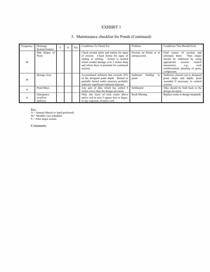
EXHIBIT 1
3. Maintenance checklist for Ponds (Continued)
Frequency Drainage System Feature Y N NA Conditions To Check For Problem Conditions That Should Exist
M
Side Slopes of Pond
Check around inlets and outlets for signs of erosion. Check berms for signs of sliding or settling. Action is needed where eroded damage over 2 inches deep and where there is potential for continued erosion.
Erosion on berms or at entrance/exit.
Find causes of erosion and eliminate them. Then slopes should be stabilized by using appropriate erosion control measure(s); e.g., rock reinforcement, planting of grass, compaction.
M
Storage Area Accumulated sediment that exceeds 10% of the designed pond depth. Buried or partially buried outlet structure probably indicates significant sediment deposits.
Sediment buildup in pond.
Sediment cleaned out to designed pond shape and depth; pond reseeded if necessary to control erosion.
A Pond Dikes Any part of dike which has settled 4 inches lower than the design elevation.
Settlement Dike should be built back to the design elevation.
A Emergency overflow spillway
Only one layer of rock exists above native soil in area 5 square feet or larger, or any exposure of native soil.
Rock Missing Replace rocks to design standards.
Key: A = Annual (March or April preferred) M = Monthly (see schedule) S = After major storms. Comments:

EXHIBIT 1
4. Maintenance Checklist for Infiltration Systems
Frequency Drainage System Feature Y N NA Conditions to Check For Problem Conditions That Should Exist
M, S General See “Ponds” Standard No. 3 Trash & Debris See “Ponds” Standard No. 3 M See “Ponds” Standard No. 3 Poisonous Vegetation See “Ponds” Standard No. 3
M, S See “Ponds” Standard No. 3 Pollution See “Ponds” Standard No. 3
M See “Ponds” Standard No. 3 Unmowed Grass/ Ground Cover
See “Ponds” Standard No. 3
M See “Ponds” Standard No. 3 Rodent Holes See “Ponds” Standard No. 3 M See “Ponds” Standard No. 3 Insects See “Ponds” Standard No. 3
M
Storage Area A percolation test-pit or test of facility indicates facility is only working at 90% of its designed capabilities.
Sediment Sediment is removed and/or facility is cleaned so that infiltration system works according to design.
M Sheet cover is visible and has more than three 1/4 – inch holes in it.
Sheet Cover (if applicable)
Sheet cover repaired or replaced.
M, S
Any sediment and debris filling vault to 10% of depth from sump bottom to bottom of outlet pipe or obstructing flow into the connector pipe.
Sump Filled with Sediment and Debris (if applicable)
Clean out sump to design depth.
M, S Filter Bags Sediment and debris fill bag more than ½ full.
Filled with Sediment and Debris
Replace filter bag or redesign system.
M, S Rock Filters By visual inspection, little or no water
flows through the filter during heavy rain storms.
Sediment and Debris Replace gravel in rock filter.
Key: A = Annual (March or April preferred) M = Monthly (see schedule) S = After major storms. Comments:

EXHIBIT 1
5. Access Roads/Easements
Frequency Drainage System Feature Y N NA Conditions to Check For Problem Conditions That Should Exist
W General Road shall be swept weekly. Trash and Debris Trash and debris cleared from site.
W Debris which could damage vehicle tires (glass or metal)
Blocked Roadway Roadway free of debris which could damage tires.
M, S Any obstructions which reduce clearance above road surface to less than 14 feet.
Roadway overhead clear to 14 feet high.
W, S
Any obstructions restricting the access to a 10-to-20 -foot width for a distance of more than 12 feet or any point restricting access to less than a 10-foot width.
Obstruction removed to allow at least a 12 foot access.
M
Road Surface When any surface defect exceeds 6-inches in depth and 6 square feet in area. In general, any surface defect which hinders or prevents maintenance access.
Settlement, Potholes, Mush, Spots, Ruts
Road surface uniformly smooth with no evidence of settlement, potholes, mush spots or ruts.
Weeds growing in the road surface that are more than 6 inches tall and less than 6 inches apart within a 400-square foot area.
Vegetation in Road Surface
Road surface free to weeds taller than 2 inches.
M, S Shoulders and Ditches
Erosion within 1 foot of the roadway more than 8 inches wide and 6 inches deep.
Erosion Damage Shoulder free of erosion and matching the surrounding road.
M Weeds and brush exceed 18 inches in
height or hinder maintenance access. Weeds and Brush Weeds and brush cut to 2 inches
in height or cleared in such a way as to allow maintenance access.
SA Pavement Markings
Pavement marks shall be painted yearly. Faded Marks All pavement markings to be obvious.
Key: SA = Annual (March or April preferred) M = Monthly (see schedule) W = Weekly (see schedule) S = After major storms. Comments:

EXHIBIT 1
6. Maintenance Checklist for Closed Detention Systems (Pipes/Tanks)
Frequency Drainage System Feature Y N NA Conditions to Check For Problem Conditions That Should Exist
M
Storage Area (Pipe/Tank)
One-half of the end area of a vent is blocked at any point with debris and sediment. Plugged vent can cause storage area to collapse.
Plugged air vents (small pipe that connects catch basin to storage pipe)
Vents free of debris and sediment.
M
Accumulated sediment depth exceeds 15% of diameter. Example: 72-inch storage tank would require cleaning when sediment reaches depth of 10 inches.
Debris and Sediment All sediment and debris removed from storage area. Contact City Public Works for guidance on sediment removal and disposal.
A Any crack allowing material to leak into facility.
Joints between tank/pipe sections.
All joints between tank/pipe sections are sealed.
A Any part of tank/pipe is noticeably bent
out of shape. Tank/pipe bent out of shape.
Tank/pipe repaired or replaced to design. Contact a professional engineer for evaluation.
M, S Manhole Cover is missing or only partially in
place. Any open manhole requires maintenance.
Cover not in place. Manhole is closed.
A
Mechanism cannot be opened by one maintenance person with proper tools. Bolts into frame have less than ½-inch of thread (may not apply to self-locking lids).
Locking mechanism not working
Mechanism opens with proper tools.
A Control device is not working properly
due to missing, out of place, or bent orifice plate.
Damaged or Missing Plate is in place and works as designed.
A
One maintenance person cannot remove lid after applying 80 pounds of lift. Intent is to keep cover from sealing off access to maintenance.
Cover difficult to remove.
Cover can be removed and reinstalled by one maintenance person.
A
Maintenance person judges that ladder is unsafe due to missing rungs, misalignment, not securely attached to structure, rust, or cracks.
Ladder rungs unsafe Ladder meets design standards and allows maintenance persons safe access.
Key: A = Annual (March or April preferred) M = Monthly (see schedule) S = After major storms. Comments:

EXHIBIT 1
7. Maintenance Checklist for Control Structure/Flow Restrictor (structure that controls rate at which water exits facility)
Frequency Drainage
System Feature Y N NA Conditions to Check For Problem Conditions That Should Exist
M Structure Distance between debris buildup and
bottom of orifice plate is less than 1 ½ feet
Trash and debris (includes sediment)
All trash and debris removed.
A
Structure is not securely attached to manhole wall and outlet pipe structure should support at least 1,000 pounds of up or down pressure.
Structural damage Structure securely attached to wall and outlet pipe.
A Structure is not in upright position (allow up to 10% from plumb).
Structure in correct position.
A Connections to outlet pipe are not
watertight and show signs of rust. Connections to outlet pipe are watertight; structure repaired or replaced and works as designed.
M Any holes (other than designed holes) in the structure.
Structure has no holes other than designed holes.
M, S Cleanout Gate Cleanout gate is not watertight or is missing.
Damaged or missing Gate is watertight and works as designed.
A Gate cannot be moved up and down by one maintenance person.
Gates moves up and down easily and is watertight.
M, S Chain leading to gate is missing or damaged.
Chain is in place and works as designed.
A Gate is rusted over 50% of its surface. Gate is repaired or replaced to meet design standards.
M, S Any trash, debris, sediment, or vegetation blocking the plate.
Obstructions Plate is free of all obstructions and works as designed.
M, S Overflow Pipe Any trash or debris blocking (or having
the potential of blocking) the overflow pipe.
Obstructions Pipe is free of all obstructions and works as designed.
Key: A = Annual (March or April preferred) M = Monthly (see schedule) S = After major storms. Comments:

EXHIBIT 1
7a. Maintenance Checklist for Pump System
Frequency Drainage System Feature Y N NA Conditions To Check For Problem Conditions That Should Exist
M Pump Wetwell Probe for sediment and check for floating debris.
Trash & Debris Includes sediment
All trash, debris, and sediment to be removed.
M Pump float switches
Are the floats caught-up or intertwined. Red alarm light Floats should hang freely and at the proper spacing.
M Pumps Check amp draw. If high, pull pump. Pumps are kicking out Full load amps should be less than 6.9 amps.
A Pumps Pull pump and check oil reservoir to see if there is water.
Pumps are not pumping as they should.
Replace oil annually and seals and/or bearing if necessary.
Key: A = Annual (March or April preferred) M = Monthly (see schedule) S = After major storms. Comments:

EXHIBIT 1
8. Maintenance Checklist for Energy Dissipaters
Frequency Drainage System Feature Y N NA Conditions to Check For Problem Conditions That Should Exist
A Rock Pad Only one layer of rock exists above
native soil in area 5 square feet or larger, or any exposure of native soil.
Missing or moved rock Replace rocks to design standard.
A
Rock-filled trench for the discharge from pond
Trench is not full of rock. Missing or moved rock Add large rock (+30 lb. Each) so that rock is visible above edge of trench.
M Dispersion Trench
Accumulated sediment that exceeds 20% of the design depth.
Pipe plugged with sediment
Pipe cleaned/flushed.
M Over ½ of perforations in pipe are plugged with debris and sediment.
Perforations plugged Clean or replace perforated pipe.
M, S
Visual evidence of water at concentrated points along trench (normal condition is a "sheet flow" of water along trench). Intent is to prevent erosion damage.
Not discharging water properly
Trench must be redesigned or rebuilt to standard. Elevation of lip of trench should be the same (flat) at all points.
M, S
Maintenance person observes water flowing out during any storm less than the design storm or it is causing or appears likely to cause damage.
Water flows out top of “distribution” catch basin
Facility must be rebuilt or redesigned to standards. Pipe is probably plugged or damaged and needs replacement.
M, S Water in receiving area is causing or has
potential of causing landslide. Receiving area over-saturated.
Stabilize slope with grass or other vegetation, or rock if conditions is severe.
Key: A = Annual (March or April preferred) M = Monthly (see schedule) S = After major storms. Comments:

EXHIBIT 1
9. Maintenance Checklist for Fencing/Shrubbery Screen/Other Landscaping
Frequency Drainage System Feature Y N NA Conditions To Check For Problem Conditions That Should Exist
M General Any debris in the fence or screen that
permits easy entry to a facility. Missing or broken parts/dead shrubbery
Fence is mended or shrubs replaced to form a solid barrier to entry.
M, S Erosion has resulted in an opening under
a fence that allows entry by people or pets.
Erosion Replace soil under fence so that no opening exceeds 4 inches in height.
M
Shrubbery is growing out of control or is infested with weeds.
Unruly vegetation Shrubbery is trimmed and weeded to provide appealing aesthetics. Do not use chemicals to control weeds.
A Wire Fences Posts out of plumb more than 6 inches. Damaged parts Posts plumb to within 1 ½ inches of plumb.
A Top rails bent more than 6 inches. Top rail free of bends greater than 1 inch
A Any part of fence (including posts, top
rails, and fabric) more than 1 foot out of design alignment.
Fence is aligned and meets design standards.
A Missing or loose tension wire. Tension wire in place and holding fabric.
A Missing or loose barbed wire that is
sagging more than 2 ½ inches between posts.
Barbed wire in place with less than ¾-inch sag between posts.
A Extension arm missing, broken, or bent out of shape more than 1 ½ inches.
Extension arm in place with no bends larger than ¾ inch.
A Part or parts that have a rusting or scaling
condition that has affected structural adequacy.
Deteriorated paint or protective coating.
Structurally adequate posts or parts with a uniform protective coating.
M Openings in fabric are such that an 8-inch diameter ball could fit through.
Opening in fabric. No openings in fabric.
Key: A = Annual (March or April preferred) M = Monthly (see schedule) S = After major storms. Comments:

EXHIBIT 1
10. Maintenance Checklist for Grounds (Landscaping)
Frequency Drainage System Feature Y N NA Conditions To Check For Problem Conditions That Should Exist
M General Weeds growing in more that 20% of the landscaped area (trees and shrubs only).
Weeds (nonpoisonous) Weeds present in less than 5% of the landscaped area.
M Any presence of poison ivy or other poisonous vegetation or insect nests.
Safety hazard No poisonous vegetation or insect nests present in landscaped area.
M, S See Ponds Checklist Trash or litter See Ponds Checklist
M, S
Noticeable rills are seen in landscaped areas.
Erosion of Ground Surface
Causes of erosion are identified and steps taken to slow down/spread out the water. Eroded areas are filled, contoured, and seeded.
A
Trees and shrubs
Limbs or parts of trees or shrubs that are split or broken which affect more than 25% of the total foliage of the tree or shrub.
Damage Trim trees/shrubs to restore shape. Replace trees/shrubs with severe damage.
M Trees or shrubs that have been blown
down or knocked over. Replant tree, inspecting for injury to stem or roots. Replace if severely damaged.
A Trees or shrubs which are not adequately
supported or are leaning over, causing exposure of the roots.
Place stakes and rubber-coated ties around young trees/shrubs for support.
Key: A = Annual (March or April preferred) M = Monthly (see schedule) S = After major storms. Comments:

11. Maintenance Checklist for Bioretention Facilities
Frequency Drainage
System Feature Y N NA Conditions To Check For Problem Conditions That Should Exist
BA
General Established vegetation with a minimum 80% survival rate.
Drought or drowning Watering may be required during prolonged dry periods, even after plants are established. Replant vegetation for poor performing plants and/or barren soils.
BA, S Maintain proper flow of stormwater from
paved/impervious areas to bioretention facility.
Flow path blocked or detoured
Remove debris and re-direct water to inlet/entrance.
BA Weeds growing in more that 20% of the landscaped area.
Evasive vegetation Remove undesired weeds and vegetation.
A Bare soils where mulch is missing. Replace mulch to a depth of 2-3 inches.
BA Any trash, debris, sediment, or vegetation blocking or clogging infrastructure.
Trash/debris Remove all trash and debris from bioretention area.
A Rock filled trench/pad
Vegetation clogging/blocking inlet and overflow infrastructures.
Remove vegetation within 1 foot of inlets and outfalls.
A Sediment build up clogging infrastructure Sediment Remove sediment and replace
soil, vegetation and mulch layer where erosion is visible.
A Maintain proper infiltration rates and drainage. Check under-drains.
Clean/Jet under-drains.
BA
Check around inlets, outlets and sidewalls for signs of erosion. Check berms for signs of sliding or settling. Action is needed where eroded damage over 2 inches deep and where there is potential for continued erosion.
Remove sediment and re-grade side slopes. Replant and mulch where barren soils are exposed.
Key: A = Annual (March or April preferred) BA = Bi-Annual M = Monthly (see schedule) S = After major storms. Comments:

12. Maintenance Checklist for Permeable Pavement
Frequency Drainage
System Feature Y N NA Conditions To Check For Problem Conditions That Should Exist
M
General Accumulated sediment and debris deposits clogging pavement and reducing infiltration rate.
Sediment deposits Plant vegetation or mulch on exposed soils. Use street sweeper with vacuum to clean surface or pressure washer.
M, S
Eco-Stone Pavers
Accumulated sediment and debris deposits clogging pavers and reducing infiltration rate.
Plant vegetation or mulch on exposed soils. Use street sweeper with vacuum to clean surface or pressure washer.
M Pavers have cracks or are broken. Damage Replace individual broken pavers.
A Weeds growing in between pavers Weeds Remove weeds manually. Do not apply herbicides.
A Gravelpave2 A A A A A M
Key: A = Annual (March or April preferred) M = Monthly (see schedule) S = After major storms. Comments:

13. Maintenance Checklist for Vegetated Roof Surfaces
Frequency Drainage System Feature Y N NA Conditions To Check For Problem Conditions That Should Exist
M General M, S
M A A A A A A A M
Key: A = Annual (March or April preferred) M = Monthly (see schedule) S = After major storms. Comments:

EXHIBIT 2
POLLUTION SOURCE CONTROL PROGRAM
WHAT ARE POLLUTION SOURCE CONTROLS, AND WHY ARE THEY NEEDED? Pollution source controls are actions taken by a person or business to reduce the amount of pollution reaching surface and ground waters. Controls, also called "best management practices" (BMPs), include:
• Altering the activity (e.g., substitute non-toxic products, recycle used oil, reroute floor drains to sanitary sewer from storm sewer).
• Enclosing or covering the activity (e.g., building a roof)
• Segregating the activity (e.g., diverting runoff away from an area that is
contaminated)
• Routing runoff from the activity to a treatment alternative (e.g., to a wastewater treatment facility, sanitary sewer, or stormwater treatment area).
Pollution source controls are needed because of the contamination found in runoff from commercial areas and the effect of this contamination on aquatic life and human health. Research on urban runoff in the Puget Sound area and elsewhere has found oil and grease, nutrients, organic substances, toxic metals, bacteria, viruses, and sediments at unacceptable levels. Effects of contaminated runoff include closure of shellfish harvesting areas and swimming areas, mortality of young fish and other aquatic organisms, tumors on fish, and impairment of fish reproduction. PROFESSIONAL SERVICES DESCRIPTION: Presented here are the remaining service businesses including theaters; hotels/motels; finance, banking, hospitals and medical services; nursing homes, schools and universities, and legal, financial and engineering services. MATERIALS USED AND WASTES GENERATED: The primary concern is runoff from parking areas. Stormwater from parking lots will contain undesirable concentrations of oil and grease, suspended particulates, and metals such as lead, cadmium, and zinc. It will also contain the organic byproducts of engine combustion. Some also produce Dangerous Wastes, for example, hospitals, nursing homes, and other medical services. These materials are stored within the building until disposal. REQUIRED ACTIONS: The following actions shall be taken to ensure that pollution generated on site shall be minimized:

1. Warning signs (e.g., "Dump No Waste--Drains to Stream") shall be painted or embossed on or adjacent to all storm drain inlets. They shall be repainted as needed.
2. Parking lots shall be swept when necessary to remove debris and, at a minimum, twice a
year. Use of newer model high-velocity vacuum sweepers is recommended as they are more effective in removing the more harmful smaller particles from paved surfaces.
3. Sediment removed from ponds/catch basins shall be disposed of in a proper manner.
Contact the City for instruction prior to completing this task. 4. No activities shall be conducted on site that is likely to result in short-term high-
concentration discharge of pollution to the stormwater system. Such activities may include, but are not limited to; vehicle washing, vehicle maintenance, and cleaning of equipment used in the periodic maintenance of buildings and paved surfaces.
5. Employees shall receive basic instruction regarding the control of pollution from
commercial operations. Contact the Public Works Department at (253) 863-8300. 6. Medical offices with high volume customer contacts have potential to influence
individuals' water quality practices. Owners are encouraged to have informational brochures provided by the City (see Item 5 above) available in waiting rooms.
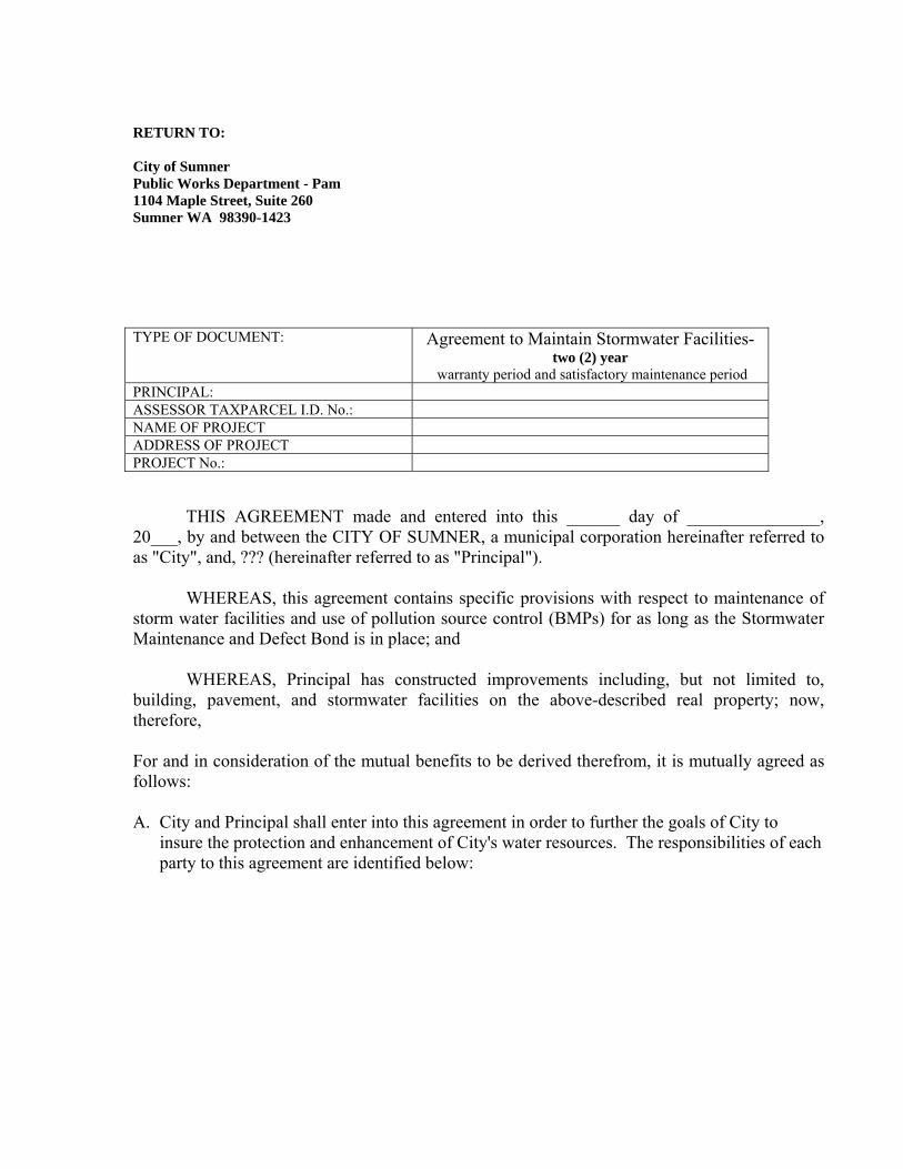
RETURN TO: City of Sumner Public Works Department - Pam 1104 Maple Street, Suite 260 Sumner WA 98390-1423 TYPE OF DOCUMENT: Agreement to Maintain Stormwater Facilities-
two (2) year warranty period and satisfactory maintenance period
PRINCIPAL: ASSESSOR TAXPARCEL I.D. No.: NAME OF PROJECT ADDRESS OF PROJECT PROJECT No.: THIS AGREEMENT made and entered into this ______ day of _______________, 20___, by and between the CITY OF SUMNER, a municipal corporation hereinafter referred to as "City", and, ??? (hereinafter referred to as "Principal"). WHEREAS, this agreement contains specific provisions with respect to maintenance of storm water facilities and use of pollution source control (BMPs) for as long as the Stormwater Maintenance and Defect Bond is in place; and WHEREAS, Principal has constructed improvements including, but not limited to, building, pavement, and stormwater facilities on the above-described real property; now, therefore, For and in consideration of the mutual benefits to be derived therefrom, it is mutually agreed as follows: A. City and Principal shall enter into this agreement in order to further the goals of City to
insure the protection and enhancement of City's water resources. The responsibilities of each party to this agreement are identified below:

1. Principal shall:
o Implement the stormwater facility maintenance program included herein as Exhibit "1".
o Implement the pollution source control program included herein as Exhibit "2".
o Maintain a record (in the form of a log book) of steps taken to implement the programs referenced in "a" and "b" above. The log book shall be available for inspection by the City staff at Principal’s business address:
196 Main Street.
o The log book shall catalog the action taken, who took it, when it was done, how it was
done, and any problems encountered or follow-up actions recommended. Maintenance items ("problems") listed in Exhibit "1" shall be inspected on a monthly or more frequent basis, as necessary. Principal is encouraged to photocopy the individual checklists in Exhibit "1" and use them to complete its monthly inspections. These completed checklists would then, in combination, comprise the monthly log book.
o Submit an annual report to the City regarding implementation of the programs referenced
in "a" and "b" above. The report must be submitted on or before May 15th of each calendar year that the Stormwater Maintenance & Defect Bond is in place, and shall contain, at a minimum, the following:
(1) Name, address and telephone number of the business, the person or the firm
responsible for plan implementation, and the person completing the report.
(2) Time period covered by the report.
(3) A chronological summary of activities conducted to implement the programs referenced in "a" and "b" above. A photocopy of the applicable sections of the log book, with any additional explanation needed, shall normally suffice. For any activities conducted by paid parties not affiliated with Principal, include a copy of the invoice for services.
(4) An outline of planned activities for the next year.

2. City shall:
a. Provide technical assistance to Principal, in support of its operation and maintenance activities conducted pursuant to its maintenance and source control programs. Said assistance shall be provided upon request, and as City time and resources permit, at no charge to Principal.
b. Review the annual report and conduct a minimum of one (1) site visit per year to
discuss performance and problems with Principal.
B. Remedies:
1. If the City determines that maintenance or repair work is required to be done to the stormwater facility, the Director of the Department of Public Works shall give the person or agent in control, notice of the specific maintenance and/or repair required. The Director shall set a reasonable time in which such work is to be completed by the persons who were given notice. If the above required maintenance and/or repair is not completed within the time set by the Director, written notice will be sent to the persons who were given notice stating City's intention to perform such maintenance and request the surety amount for all incurred expenses.
2. If at any time City determines that the existing system creates any eminent threat to
public health or welfare, the Director may take immediate measures to remedy said threat. Under such circumstances no notice to the persons listed in B.1 above shall be required, but the City shall give the Principal immediate notice of the remedial measures so taken
3. The persons listed in B.1 above shall assume all responsibility for the cost of any
maintenance and for repairs to the stormwater facility. Such responsibility shall include reimbursement to City within thirty (30) days of the receipt of the invoice for any such work performed. Overdue payments will require payment of interest at the current legal rate for liquidated judgments. If legal action ensues, any costs or fees incurred by City will be borne by the parties responsible for said reimbursements.
4. In the event Principal fails to pay City within thirty (30) days from the date that the costs
were incurred, City shall have the right to file a lien against for all charges and expenses incurred. A lien specifying the expenses incurred and giving a legal description of the premises sought to be charged shall be filed with the County Auditor within ninety (90) days from the date of the completion of the work. The same may at any time thereafter be collected in the manner provided for foreclosure of mechanic's liens under the laws of the State of Washington.

C. Intent:
1. This agreement is intended to protect the value and desirability of the real property described above and to benefit all the citizens of the City and shall run with the Stormwater Maintenance & Defect Bond.
IN WITNESS WHEREOF, the parties have executed this agreement the day and year first above written. PRINCIPAL SIGNATURE:
By: By:
Its: Its:
STATE OF WASHINGTION ) ) SS COUNTY OF PIERCE )
On this __________________ day of _______________________, 20___, before me, the undersigned, a Notary Public in and for the State of Washington, duly commissioned and sworn personally appeared ____________________________________________, to me proven to be the individual described in and who executed the foregoing instrument for himself and acknowledged that he signed the same as his free and voluntary act and deed for himself and also as his free and voluntary act and deed as of said CORPORATION, for uses and purposes therein mentioned, and on oath stated that he was authorized to execute the said instrument. IN WITNESS WHEREOF, I have hereunto set my hand and official seal the day and year first above written.
Printed Name: NOTARY PUBLIC in and for the State
Washington, residing at My Commission Expires:

CITY OF SUMNER
By: By:
David L. Enslow Mayor Diane L. Supler City Administrator
STATE OF WASHINGTION ) ) SS COUNTY OF PIERCE )
On this ____________________ day of ______________________________, 20___, before me, the undersigned, a Notary Public in the State of Washington, duly commissioned and sworn, personally appeared David L. Enslow and Diane L. Supler, representing themselves as Mayor and City Administrator, respectively, of the City of Sumner, the municipal corporation that executed the foregoing instrument, and acknowledged the instrument to be the free and voluntary act and deed of said municipal corporation for the uses and purposes therein mentioned, and on oath stated that they are authorized to execute the same. IN WITNESS WHEREOF, I have hereunto set my hand and official seal the day and year first above written.
Printed Name:
NOTARY PUBLIC in and for the State
Washington, residing at My Commission Expires:
Approved to Form: ATTEST:
By: By:
Brett Vinson City Attorney Terri Berry City Clerk
Approved By:
William L. Pugh, Public Works Director TYPE OF DOCUMENT: Agreement to Maintain Stormwater Facilities-
two (2) year warranty period and satisfactory maintenance period
PRINCIPAL: ASSESSOR TAXPARCEL I.D. No.: NAME OF PROJECT ADDRESS OF PROJECT PROJECT No.:

EXHIBIT 'A' - STORMWATER MAINTENANCE AGREEMENT Legal Description

EXHIBIT 1: MAINTENANCE PROGRAM - COVER SHEET
TYPE OF DOCUMENT: Agreement to Maintain Stormwater Facilities ASSESSOR TAXPARCEL I.D. No.: COMPANY NAME: ADDRESS OF SITE: (REQUIRED)
STORMWATER MAINTENANCE NUMBER:
Inspection Period: ANNUALLY by May 15 Date Inspected:
On-site Contact Name (print) (REQUIRED)
Site Contact Mailing Address:
Site Contact Telephone number: (REQUIRED)
Site Contact email address:
City inspection signature:

EXHIBIT 1 MAINTENANCE PROGRAM 1. Maintenance checklist for Catch Basins and Inlets Frequency Drainage
System Feature X Problem Conditions to Check For Conditions That Should Exist
M, S
General Trash, debris and sediment in or on basin
Trash or debris in front of the catch basin opening is blocking capacity by more than 10%.
No trash or debris located immediately in front of catch basin opening. Grate is kept clean and allows water to enter.
M
Sediment or debris (in the basin) that exceeds 1/3 depth from the bottom of basin to invert of the lowest pipe into or out of the basin.
No sediment or debris in the catch basin. Catch basin is dug out and clean.
M, S Trash or debris in any inlet or pipe blocking more than 1/3 of height.
Inlet and outlet pipes free of trash or debris.
M, S
Dead animals or vegetation that could generate odors that would cause complaints or dangerous gases (e.g., methane).
No dead animals or vegetation present within the catch basin.
M, S Deposits of garbage exceeding 1
cubic foot in volume. No condition present which would attract or support the breeding of insects or rodents.
M Structural damage
to frame and/or top slab.
Corner of frame extends more than ¾ inch past curb face into the street (if applicable)
Frame is even with curb.
M
Top slab has holes larger than 2 square inches or cracks wider than ¼ inch (intent is to make sure all material is running into the basin)
Top slab is free of holes and cracks.
M Frame is not sitting flush on top
slab i.e., separation of more than ¾ inch of the frame from the top slab.
Frame is sitting flush on top slab.
A
Cracks in basin walls/bottom
Cracks wider than ½ inch and longer than 3 feet, any evidence of soil particles entering catch basin through cracks or maintenance person judges that structure is unsound.
Basin replaced or repaired to design standards. Contact a professional engineer for evaluation.
A
Cracks wider than ½ inch and longer than 1 foot at the joint of any inlet/outlet pipe or any evidence of soil particles entering catch basin through cracks.
No cracks more than ¼-inch wide at the joint of inlet/outlet pipe.
A
Settlement/ Misalignment
Basin has settled more than 1 inch or has rotated more than 2 inches out of alignment.
Basin replaced or repaired to design standards. Contact a professional engineer for evaluation.
M, S
Fire hazard or other pollution
Presence of chemicals such as natural gas, oil, or gasoline. Obnoxious color, odor, or sludge noted.
No color, odor, or sludge. Basin is dug out and clean.

EXHIBIT 1 (Continued) 1. Maintenance checklist for Catch Basins and Inlets (continued) Frequency Drainage
System Feature X Problem Conditions to Check For Conditions That Should Exist
M, S
Outlet pipe is clogged with vegetation.
Vegetation or roots growing in inlet/outlet pipe joints that is more than six inches tall and less than six inches apart.
No vegetation or root growth present.
M, S Vegetation Vegetation growing across and
blocking more than 10% of the basin opening.
No vegetation blocking opening to basin.
M, S Pollution Non-flammable chemicals of more
than ½ cubic foot per three feet of basin length.
No pollution present other than surface film.
M, S Catch Basin Cover
Cover not in place
Cover is missing or only partially in place. Any open catch basin requires maintenance.
Catch basin cover is closed.
A
Locking Mechanism Not Working
Mechanism cannot be opened by one maintenance person with proper tools. Bolts into frame have less than ½ inch of thread.
Mechanism opens with proper tools.
A
Cover Difficult to Remove
One maintenance person cannot remove lid after applying 80 lbs of lift; intent is to keep cover from sealing off access to maintenance.
Cover can be removed by one maintenance person.
A Ladder Ladder Rungs
Unsafe Ladder is unsafe due to missing rungs, misalignment, rust, cracks, or sharp edges.
Ladder meets design standards and allows maintenance person safe access.
M, S Metal Grates (if applicable)
Trash and Debris
Trash and debris that is blocking more than 20% of grate surface.
Grate free of trash and debris.
M, S Damaged or Missing
Grate missing or broken member(s) of the grate.
Grate is in place and meets design standards.
Key: A = Annual (March or April preferred) M = Monthly (see schedule) S = After major storms. Comments:

EXHIBIT 1 (Continued)
2. Maintenance Checklist for Conveyance Systems
Frequency Drainage System Feature
X Problem Conditions to Check For Conditions That Should Exist
M, S Pipes Sediment & debris
Accumulated sediment that exceeds 20% of the diameter of the pipe.
Pipe cleaned of all sediment and debris.
M Vegetation Vegetation that reduces free movement
of water through pipes. All vegetation removed so water flows freely through pipes.
A
Damaged (rusted, bent, or crushed)
Protective coating is damaged; rust is causing more than 50% deterioration to any part of pipe.
Pipe repaired or replaced.
M Any dent that significantly impedes flow
(i.e., decreases the cross section area of pipe by more than 20%)
Pipe repaired or replaced.
M Pipe has major cracks or tears allowing groundwater leakage.
Pipe repaired or replaced.
M, S
Open ditches Trash & debris
Dumping of yard waste such as grass clippings and branches into basin. Unsightly accumulation of nondegradable materials such as glass, plastic, metal, foam, and coated paper.
Remove trash and debris and dispose as prescribed by city Waste Management Section.
M Sediment
buildup Accumulated sediment that exceeds 20% of the design depth
Ditch cleaned of all sediment and debris so that it matches design.
A Vegetation Vegetation (e.g., weedy shrubs or
saplings) that reduces free movement of water through ditches.
Water flows freely through ditches. Grassy vegetation should be left alone.
M Erosion
damage to slopes
See "Ponds" Checklist See "Ponds" Checklist
A
Rock lining out of place or missing (if applicable)
Maintenance person can see native soil beneath the rock lining.
Replace rocks to design standard.
Varies Catch Basins See "Catch Basins" Checklist See "Catch Basins" Checklist
M, S Swales Trash & debris
See above for "Ditches" See above for "Ditches"
M Sediment Buildup
See above for "Ditches" Vegetation may need to be replanted after cleaning.
M
Vegetation not growing or overgrown
Grass cover is sparse and weedy or areas are overgrown with woody vegetation.
Aerate soils and reseed and mulch bare areas. Maintain grass height at a minimum of 6 inches for best stormwater treatment or a minimum of 2 inches above the design flow depth. Remove woody growth, recontour, and reseed as necessary.
M, S Erosion
damage to slopes
See Ponds Checklist See Ponds Checklist
EXHIBIT 1 (Continued)
2. Maintenance Checklist for Conveyance Systems

M
Conversion by homeowner to imcompatible use
Swale has been filled in or blocked by shed, woodpile, shrubbery, etc.
If possible, speak with homeowner and request that swale area be restored. Contact City to report problem if not rectified voluntarily.
A
Swale does not drain.
Water stands in swale or flow velocity is very slow. Stagnation occurs.
A survey may be needed to check grades. Grades need to be in 1 - 5% range if possible. If grade is less than 1%, underdrains may need to be installed.

EXHIBIT 1 (Continued)
3. Maintenance checklist for Ponds. Frequency Drainage
System Feature X Problem Conditions for Check For Conditions That Should
Exist
M, S
General Trash & debris buildup in pond
Any trash and debris which exceeds 1 cubic foot per 1000 square feet (this is about equal to the amount of trash it would take to fill up one standard size office garbage can). In general, there should be no visual evidence of dumping.
Trash and debris cleared from site.
M, S
Trash rack plugged or missing
Bar screen over outlet more than 25% covered by debris or missing.
Replace screen. Remove trash and debris and dispose as prescribed by City Waste Management Section.
M
Poisonous Vegetation
Any poisonous vegetation which may constitute a hazard to the public. Examples of poisonous vegetation include: tansy ragwort, poison oak, stinging nettles, devils club.
Remove poisonous vegetation. Do not spray chemicals on vegetation without obtaining guidance from the Cooperative Extension Service and approval from the City.
M, S
Fire hazard or pollution
Oil, gasoline, or other contaminants of one gallon or more or any amount found that could: 1) cause damage to plant, animal, or marine life; 2) constitute a fire hazard; or 3) be flushed downstream during rain storms. Presence of chemicals such as natural gas, obnoxious color, odor, or sludge noted.
Find sources of pollution and eliminate them. Water is free from noticeable color, odor or contamination.
M
Vegetation not growing or is overgrown.
For grassy ponds, gross cover is sparse and weedy or is overgrown. For wetland ponds, plants are sparse or invasive species are present. Wetland ponds must be kept wet--water frequently in summer.
For grassy ponds, selectively thatch, aerate and reseed ponds. Grass cutting unnecessary unless dictated by aesthetics. For wetland ponds, hand-plant nursery-grown wetland plants in bare areas. Pond bottoms should have uniform dense coverage of desired plant species.
M Rodent
holes Any evidence of rodent holes if facility is acting as a dam or berm., or any evidence of water piping through dam or berm via rodent holes.
Rodents destroyed and dam or berm repaired.
M Insects When insects such as wasps and hornets
interfere with maintenance activities, or when mosquitoes become a nuisance.
Insects destroyed or removed from site.
A
Tree growth
Tree growth does not allow maintenance access or interfere with maintenance activity (i.e., slope mowing, silt removal, or equipment movements). If trees are not interfering with access, leave trees alone.
Trees do not hinder maintenance activities. Selectively cultivate trees such as alder for firewood.

EXHIBIT 1 (Continued)
3. Maintenance checklist for Ponds. (continued)
Frequency Drainage System Feature X Problem Condition to Check For Conditions That Should Exist
M
Side slopes of pond Erosion on berms or at entrance/exit.
Check around inlets and outlets for signs of erosion. Check berms for signs of sliding or settling. Action is needed where eroded damage over 2 inches deep and where there is potential for continued erosion.
Find causes of erosion and eliminate them. Then slopes should be stabilized by using appropriate erosion control measure(s); e.g., rock reinforcement, planting of grass, compaction.
M
Storage area Sediment buildup in pond.
Accumulated sediment that exceeds 10% of the designed pond depth. Buried or partially buried outlet structure probably indicates significant sediment deposits.
Sediment cleaned out to designed pond shape and depth; pond reseeded if necessary to control erosion.
A Pond dikes Settlement Any part of dike which has
settled 4 inches lower than the design elevation.
Dike should be built back to the design elevation.
A
Emergency/ overflow spillway
Rock missing Only one layer of rock exists above native soil in area 5 square feet or larger, or any exposure of native soil.
Replace rocks to design standards.
Key: A = Annual (March or April preferred) M = Monthly (see schedule) S = After major storms. Comments:

EXHIBIT 1 (Continued) 4. Maintenance Checklist for Infiltration Systems Frequency Drainage System
Feature X Problem Conditions to Check For Conditions That Should Exist
M, S General Trash & Debris See "Ponds" Standard No. 3 See "Ponds" Standard No. 3
M Poisonous Vegetation
See "Ponds" Standard No. 3 See "Ponds" Standard No. 3
M, S Pollution See "Ponds" Standard No. 3 See "Ponds" Standard No. 3
M Unmowed Grass/ Ground Cover
See "Ponds" Standard No. 3 See "Ponds" Standard No. 3
M Rodent Holes See "Ponds" Standard No. 3 See "Ponds" Standard No. 3 M Insects See "Ponds" Standard No. 3 See "Ponds" Standard No. 3
M
Storage Area Sediment A percolation test-pit or test of facility indicates facility is only working at 90% of its designed capabilities.
Sediment is removed and/or facility is cleaned so that infiltration system works according to design.
M Sheet Cover
(if applicable) Sheet cover is visible and has more than three ¼-inch holes in it.
Sheet cover repaired or replaced.
M, S
Sump Filled With Sediment and Debris (if applicable)
Any sediment and debris filling vault to 10% of depth from sump bottom to bottom of outlet pipe or obstructing flow into the connector pipe.
Clean out sump to design depth.
M, S Filter Bags Filled with
Sediment and Debris
Sediment and debris fill bag more than ½ full
Replace filter bag or redesign system.
M, S Rock Filters Sediment and
Debris By visual inspection, little or no water flows through filter during heavy rain storms.
Replace gravel in rock filter.
Key: A = Annual (March or April preferred) M = Monthly (see schedule) S = After major storms. Comments:
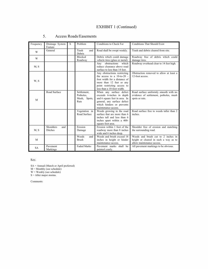
EXHIBIT 1 (Continued)
5. Access Roads/Easements Frequency Drainage System
Feature X Problem Conditions to Check For Conditions That Should Exist
W General Trash and Debris
Road shall be swept weekly. Trash and debris cleared from site.
W Blocked Roadway
Debris which could damage vehicle tires (glass or metal)
Roadway free of debris which could damage tires.
M, S Any obstructions which
reduce clearance above road surface to less than 14 feet.
Roadway overhead clear to 14 feet high.
W, S
Any obstructions restricting the access to a 10-to-20 -foot width for a distance of more than 12 feet or any point restricting access to less than a 10-foot width.
Obstruction removed to allow at least a 12-foot access.
M
Road Surface Settlement, Potholes, Mush, Spots, Ruts
When any surface defect exceeds 6-inches in depth and 6 square feet in area. In general, any surface defect which hinders or prevents maintenance access.
Road surface uniformly smooth with no evidence of settlement, potholes, mush spots or ruts.
Vegetation in Road Surface
Weeds growing in the road surface that are more than 6 inches tall and less than 6 inches apart within a 400-square foot area.
Road surface free to weeds taller than 2 inches.
M, S Shoulders and Ditches
Erosion Damage
Erosion within 1 foot of the roadway more than 8 inches wide and 6 inches deep.
Shoulder free of erosion and matching the surrounding road.
M Weeds and
Brush Weeds and brush exceed 18 inches in height or hinder maintenance access.
Weeds and brush cut to 2 inches in height or cleared in such a way as to allow maintenance access.
SA Pavement Markings
Faded Marks Pavement marks shall be painted yearly.
All pavement markings to be obvious.
Key: SA = Annual (March or April preferred) M = Monthly (see schedule) W = Weekly (see schedule) S = After major storms. Comments:

EXHIBIT 1 (Continued)
6. Maintenance Checklist for Closed Detention Systems (Pipes/Tanks) Frequency Drainage System
Feature X Problem Conditions to Check For Conditions That Shall Exist
M
Storage area (pipe/tank)
Plugged air vents (small pipe that connects catch basin to storage pipe)
One-half of the end area of a vent is blocked at any point with debris and sediment. Plugged vent can cause storage area to collapse.
Vents free of debris and sediment.
M
Debris and Sediment
Accumulated sediment depth exceeds 15% of diameter. Example: 72-inch storage tank would require cleaning when sediment reaches depth of 10 inches.
All sediment and debris removed from storage area. Contact City Public Works for guidance on sediment removal and disposal.
A Joints between
tank/pipe section.
Any crack allowing material to leak into facility.
All joints between tank/pipe sections are sealed.
A Tank/pipe
bent out of shape.
Any part of tank/pipe is noticeably bent out of shape.
Tank/pipe repaired or replaced to design. Contact a professional engineer for evaluation.
M, S Manhole Cover not in
place. Cover is missing or only partially in place. Any open manhole requires maintenance.
Manhole is closed.
A
Locking mechanism not working
Mechanism cannot be opened by one maintenance person with proper tools. Bolts into frame have less than ½-inch of thread (may not apply to self-locking lids).
Mechanism opens with proper tools.
A
Cover difficult to remove.
One maintenance person cannot remove lid after applying 80 pounds of lift. Intent is to keep cover from sealing off access to maintenance.
Cover can be removed and reinstalled by one maintenance person.
A
Ladder rungs unsafe
Maintenance person judges that ladder is unsafe due to missing rungs, misalignment, rust, or cracks.
Ladder meets design standards and allows maintenance persons safe access.
Key: A = Annual (March or April preferred) M = Monthly (see schedule) S = After major storms. Comments:
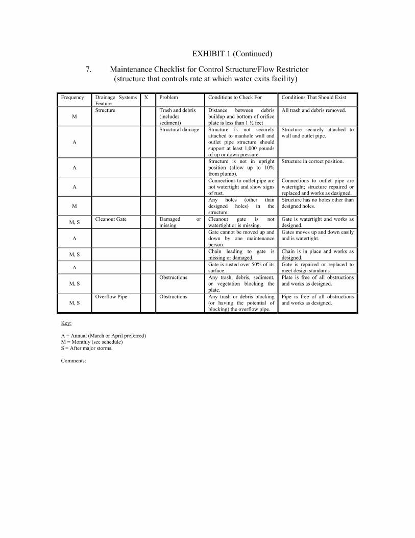
EXHIBIT 1 (Continued)
7. Maintenance Checklist for Control Structure/Flow Restrictor (structure that controls rate at which water exits facility) Frequency Drainage Systems
Feature X Problem Conditions to Check For Conditions That Should Exist
M Structure Trash and debris
(includes sediment)
Distance between debris buildup and bottom of orifice plate is less than 1 ½ feet
All trash and debris removed.
A
Structural damage Structure is not securely attached to manhole wall and outlet pipe structure should support at least 1,000 pounds of up or down pressure.
Structure securely attached to wall and outlet pipe.
A Structure is not in upright
position (allow up to 10% from plumb).
Structure in correct position.
A Connections to outlet pipe are
not watertight and show signs of rust.
Connections to outlet pipe are watertight; structure repaired or replaced and works as designed.
M Any holes (other than
designed holes) in the structure.
Structure has no holes other than designed holes.
M, S Cleanout Gate Damaged or missing
Cleanout gate is not watertight or is missing.
Gate is watertight and works as designed.
A Gate cannot be moved up and
down by one maintenance person.
Gates moves up and down easily and is watertight.
M, S Chain leading to gate is missing or damaged.
Chain is in place and works as designed.
A Gate is rusted over 50% of its surface.
Gate is repaired or replaced to meet design standards.
M, S Obstructions Any trash, debris, sediment,
or vegetation blocking the plate.
Plate is free of all obstructions and works as designed.
M, S Overflow Pipe Obstructions Any trash or debris blocking
(or having the potential of blocking) the overflow pipe.
Pipe is free of all obstructions and works as designed.
Key: A = Annual (March or April preferred) M = Monthly (see schedule) S = After major storms. Comments:

EXHIBIT 1 (Continued)
7a. Maintenance Checklist for Pump System Frequency Drainage System
Feature X Problem Conditions to Check For Conditions That Should Exist
M Pump wetwell Trash & debris Includes sediment
Probe for sediment and check for floating debris
All trash, debris, and sediment to be removed.
M Pump float switches
Red alarm light Are the floats caught-up or intertwined.
Floats should hang freely and at the proper spacing.
M Pumps Pumps are kicking out
Check amp draw. If high, pull pump.
Full load amps should be less that 6.9 amps.
A Pumps Pumps are not
pumping as they should.
Pull pump and check oil reservoir to see if there is water.
Replace oil annually and seals and/or bearing if necessary.
Key: A = Annual (March or April preferred) M = Monthly (see schedule) S = After major storms. Comments:

EXHIBIT 1 (Continued)
8. Maintenance Checklist for Energy Dissipaters Frequency Drainage System
Feature X Problem Conditions to Check For Conditions That Should Exist
A
Rock Pad Missing or moved rock
Only one layer of rock exists above native soil in area 5 square feet or larger, or any exposure of native soil.
Replace rocks to design standard.
A
Rock-filled trench for discharge from pond
Missing or moved rock
Trench is not full of rock. Add large rock (+30 lb. Each) so that rock is visible above edge of trench.
M Dispersion Trench
Pipe plugged with sediment
Accumulated sediment that exceeds 20% of the design depth.
Pipe cleaned/flushed.
M Perforations plugged Over ½ of perforations in
pipe are plugged with debris and sediment.
Clean or replace perforated pipe.
M, S
Not discharging water properly
Visual evidence of water at concentrated points along trench (normal condition is a "sheet flow" of water along trench). Intent is to prevent erosion damage.
Trench must be redesigned or rebuilt to standard. Elevation of lip of trench should be the same (flat) at all points.
M, S
Water flows out top of "distributor" catch basin
Maintenance person observes water flowing out during any storm less than the design storm or it is causing or appears likely to cause damage.
Facility must be rebuilt or redesigned to standards. Pipe is probably plugged or damaged and needs replacement.
M, S Receiving area over-
saturated. Water in receiving area is causing or has potential of causing landslide.
Stabilize slope with grass or other vegetation, or rock if conditions is severe.
Key: A = Annual (March or April preferred) M = Monthly (see schedule) S = After major storms. Comments:

EXHIBIT 1 (Continued)
9. Maintenance Checklist for Fencing/Shrubbery Screen/Other Landscaping Frequency Drainage
System Feature X Problem Conditions to Checks For Conditions That Should Exist
M
General Missing or broken parts/dead shrubbery
Any debris in the fence or screen that permits easy entry to a facility.
Fence is mended or shrubs replaced to form a solid barrier to entry.
M, S Erosion Erosion has resulted in an opening
under a fence that allows entry by people or pets.
Replace soil under fence so that no opening exceeds 4 inches in height.
M
Unruly vegetation
Shrubbery is growing out of control or is infested with weeds.
Shrubbery is trimmed and weeded to provide appealing aesthetics. Do not use chemicals to control weeds.
A Wire fences Damaged parts Posts out of plumb more than 6 inches.
Posts plumb to within 1 ½ inches of plumb.
A Top rails bent more than 6 inches. Top rail free of bends greater than 1 inch.
A
Any part of fence (including posts, top rails, and fabric) more than 1 foot out of design alignment.
Fence is aligned and meets design standards.
A Missing or loose tension wire. Tension wire in place and holding fabric.
A Missing or loose barbed wire that
is sagging more than 2 ½ inches between posts.
Barbed wire in place with less than ¾-inch sag between posts.
A Extension arm missing, broken, or
bent out of shape more than 1 ½ inches.
Extension arm in place with no bends larger than ¾ inch.
A
Deteriorated paint or protective coating.
Part or parts that have a rusting or scaling condition that has affected structural adequacy.
Structurally adequate posts or parts with a uniform protective coating.
M Opening in
fabric. Openings in fabric are such that an 8-inch diameter ball could fit through.
No openings in fabric.
Key: A = Annual (March or April preferred) M = Monthly (see schedule) S = After major storms. Comments:

EXHIBIT 1 (continued) 10. Maintenance Checklist for Grounds (Landscaping) Frequency Drainage
System Feature X Problem Conditions to Checks For Conditions That Should Exist
M General Weeds
(nonpoisonous)
Weeds growing in more that 20% of the landscaped area (trees and shrubs only).
Weeds present in less than 5% of the landscaped area.
M Safety
hazard Any presence of poison ivy or other poisonous vegetation or insect nests.
No poisonous vegetation or insect nests present in landscaped area.
M,S Trash or litter
See Ponds Checklist See Ponds Checklist
M, S
Erosion of Ground Surface
Noticeable rills are seen in landscaped areas.
Causes of erosion are identified and steps taken to slow down/spread out the water. Eroded areas are filled, contoured, and seeded.
A
Trees and shrubs
Damage Limbs or parts of trees or shrubs that are split or broken which affect more than 25% of the total foliage of the tree or shrub.
Trim trees/shrubs to restore shape. Replace trees/shrubs with severe damage.
M Trees or shrubs that have been
blown down or knocked over. Replant tree, inspecting for injury to stem or roots. Replace if severely damaged.
A
Trees or shrubs which are not adequately supported or are leaning over, causing exposure of the roots.
Place stakes and rubber-coated ties around young trees/shrubs for support.
Key: A = Annual (March or April preferred) M = Monthly (see schedule) S = After major storms. Comments:

EXHIBIT 2
POLLUTION SOURCE CONTROL PROGRAM
WHAT ARE POLLUTION SOURCE CONTROLS, AND WHY ARE THEY NEEDED? Pollution source controls are actions taken by a person or business to reduce the amount of pollution reaching surface and ground waters. Controls, also called "best management practices" (BMPs), include:
• Altering the activity (e.g., substitute non-toxic products, recycle used oil, reroute floor drains to sanitary sewer from storm sewer).
• Enclosing or covering the activity (e.g., building a roof)
• Segregating the activity (e.g., diverting runoff away from an area that is
contaminated)
• Routing runoff from the activity to a treatment alternative (e.g., to a wastewater treatment facility, sanitary sewer, or stormwater treatment area).
Pollution source controls are needed because of the contamination found in runoff from commercial areas and the effect of this contamination on aquatic life and human health. Research on urban runoff in the Puget Sound area and elsewhere has found oil and grease, nutrients, organic substances, toxic metals, bacteria, viruses, and sediments at unacceptable levels. Effects of contaminated runoff include closure of shellfish harvesting areas and swimming areas, mortality of young fish and other aquatic organisms, tumors on fish, and impairment of fish reproduction. PROFESSIONAL SERVICES DESCRIPTION: Presented here are the remaining service businesses including theaters; hotels/motels; finance, banking, hospitals and medical services; nursing homes, schools and universities, and legal, financial and engineering services. MATERIALS USED AND WASTES GENERATED: The primary concern is runoff from parking areas. Stormwater from parking lots will contain undesirable concentrations of oil and grease, suspended particulates, and metals such as lead, cadmium, and zinc. It will also contain the organic byproducts of engine combustion. Some also produce Dangerous Wastes, for example, hospitals, nursing homes, and other medical services. These materials are stored within the building until disposal. REQUIRED ACTIONS: The following actions shall be taken to ensure that pollution generated on site shall be minimized: 1. Warning signs (e.g., "Dump No Waste--Drains to Stream") shall be painted or embossed
on or adjacent to all storm drain inlets. They shall be repainted as needed.

2. Parking lots shall be swept when necessary to remove debris and, at a minimum, twice a
year. Use of newer model high-velocity vacuum sweepers is recommended as they are more effective in removing the more harmful smaller particles from paved surfaces.
3. Sediment removed from ponds/catch basins shall be disposed of in a proper manner.
Contact the City for instruction prior to completing this task. 4. No activities shall be conducted on site that are likely to result in short-term high-
concentration discharge of pollution to the stormwater system. Such activities may include, but are not limited to, vehicle washing, vehicle maintenance, and cleaning of equipment used in the periodic maintenance of buildings and paved surfaces.
5. Employees shall receive basic instruction regarding the control of pollution from
commercial operations. Contact the Public Works Department at (253) 863-8300. 6. Medical offices with high volume customer contacts have potential to influence
individuals' water quality practices. Owners are encouraged to have informational brochures provided by the City (see Item 5 above) available in waiting rooms.

RETURN TO: City of Sumner Public Works Department - Pam 1104 Maple Street, Suite 260 Sumner WA 98390-1423
Please make no mark in the margin space - Reserved for County Auditor's use only.
TYPE OF DOCUMENT: Agreement to Maintain Stormwater Facilities -
individual GRANTOR(S): GRANTEE: City of Sumner, a Municipal Corporation LEGAL DESCRIPTION: Page 7, Exhibit ‘A’ of this document ABBREVIATED LEGAL DESCRIPTION: ASSESSOR TAXPARCEL I.D. No.: NAME OF PROJECT ADDRESS OF PROJECT PROJECT No.: Recording No:
AGREEMENT TO MAINTAIN STORMWATER FACILITIES AND TO IMPLEMENT A POLLUTION SOURCE CONTROL PLAN
THIS AGREEMENT made and entered into this ______ day of _______________, 20___, by and between the CITY OF SUMNER, a municipal corporation hereinafter referred to as "City", and GRANTOR NAME, (hereinafter referred to as "Owner"). WHEREAS, this agreement contains specific provisions with respect to maintenance of storm water facilities and use of pollution source control (BMPs). The authority to require maintenance and pollution source control is provided in Ordinance No. 1603; and WHEREAS, Owner owns the following-described real property situated in Pierce County, State of Washington, as set forth in Exhibit ‘A’, which is attached hereto and made a part hereof; and WHEREAS, Owner has constructed improvements including, but not limited to, building, pavement, and stormwater facilities on the above-described real property; now, therefore, For and in consideration of the mutual benefits to be derived therefrom, it is mutually agreed as follows: B. City and Owner enter into this agreement in order to further the goals of City to insure
the protection and enhancement of City's water resources. The responsibilities of each party to this agreement are identified below:

1.Owner shall:
o Implement the stormwater facility maintenance program included herein as Exhibit "1".
o Implement the pollution source control program included herein as Exhibit
"2".
o Maintain a record (in the form of a log book) of steps taken to implement the programs referenced in "a" and "b" above. The log book shall be available for inspection by the City staff at Owner's business address:
City of Sumner 1104 Maple Street Sumner, Washington 98390
o The log book shall catalog the action taken, who took it, when it was done,
how it was done, and any problems encountered or follow-up actions recommended. Maintenance items ("problems") listed in Exhibit "1" shall be inspected on a monthly or more frequent basis, as necessary. Owner is encouraged to photocopy the individual checklists in Exhibit "1" and use them to complete its monthly inspections. These completed checklists would then, in combination, comprise the monthly log book.
o Submit an annual report to City regarding implementation of the programs
referenced in "a" and "b" above. The report must be submitted on or before May 15th of each calendar year and shall contain, at a minimum, the following:
(1) Name, address and telephone number of the business, the person or the firm
responsible for plan implementation, and the person completing the report.
(2) Time period covered by the report.
(3) A chronological summary of activities conducted to implement the programs referenced in "a" and "b" above. A photocopy of the applicable sections of the log book, with any additional explanation needed, shall normally suffice. For any activities conducted by paid parties not affiliated with Owner, include a copy of the invoice for services.
(4) An outline of planned activities for the next year.

2. City shall:
a. Provide technical assistance to Owner in support of its operation and maintenance activities conducted pursuant to its maintenance and source control programs. Said assistance shall be provided upon request, and as City time and resources permit, at no charge to Owner.
b. Review the annual report and conduct a minimum of one (1) site visit per year to
discuss performance and problems with Owner.
c. Review this agreement with Owner and if necessary consider reasonable modification hereto no more than once every three (3) years.
B. Remedies:
3. If City determines that maintenance or repair work is required to be done to the
stormwater facility existing on Owner's property, the Director of the Department of Public Works shall give the owner of the property within which the drainage facility is located, and the person or agent in control of said property, notice of the specific maintenance and/or repair required. The Director shall set a reasonable time in which such work is to be completed by the persons who were given notice. If the above required maintenance and/or repair is not completed within the time set by the Director, written notice will be sent to the persons who were given notice stating City's intention to perform such maintenance and bill Owner for all incurred expenses.
2. If at any time City determines that the existing system creates any eminent threat to
public health or welfare, the Director may take immediate measures to remedy said threat. Under such circumstances no notice to the persons listed in B.1 above shall be required, but the City shall give the Owner immediate notice of the remedial measures so taken
3. The persons listed in B.1 above shall assume all responsibility for the cost of any
maintenance and for repairs to the stormwater facility. Such responsibility shall include reimbursement to City within thirty (30) days of the receipt of the invoice for any such work performed. Overdue payments will require payment of interest at the current legal rate for liquidated judgments. If legal action ensues, any costs or fees incurred by City will be borne by the parties responsible for said reimbursements.
4. In the event Owner of the property fails to pay City within thirty (30) days from the date
that the costs were incurred, City shall have the right to file a lien against the real property for all charges and expenses incurred. A lien specifying the expenses incurred and giving a legal description of the premises sought to be charged shall be filed with the County Auditor within ninety (90) days from the date of the completion of the work. The same may at any time thereafter be collected in the manner provided for foreclosure of mechanic's liens under the laws of the State of Washington.

C. Intent:
1. This agreement is intended to protect the value and desirability of the real property described above and to benefit all the citizens of the City. It shall run with the land and be binding on all parties having or acquiring from Owner or their successors, any right, title or interest in the property or any part thereof, as well as their title, or interest in the property or any part thereof, as well as their heirs, successors and assigns. They shall inure to the benefit of each present or future successor in interest of said property or any part thereof, or interest therein, and to the benefit of all citizens of City.
(Notary Acknowledgement on Next Page)

IN WITNESS WHEREOF, the parties have executed this agreement the day and year first above written.
GRANTOR
Its: Its:
STATE OF WASHINGTION ) ) SS COUNTY OF PIERCE ) On this day of , 20___, before me a Notary Public in and for the State of Washington, personally appeared to me known to be the individual that executed the foregoing instrument, and acknowledged it to be the free and voluntary act, for the uses and purposes mentioned in this instrument, and on oath stated that they were authorized to execute said instrument.
-Notary Seal Must Appear Within This Box-
IN WITNESS WHEREOF, I have hereunto set my hand and official seal the day and year first above written.
Printed Name: NOTARY PUBLIC in and for the State Washington, residing at My Commission Expires:

CITY OF SUMNER
By: By:
David L. Enslow Mayor Diane L. Supler City Administrator
STATE OF WASHINGTION ) ) SS COUNTY OF PIERCE )
On this ____________________ day of ______________________________, 20___, before me, the undersigned, a Notary Public in the State of Washington, duly commissioned and sworn, personally appeared David L. Enslow and Diane L. Supler, representing themselves as Mayor and Interim City Administrator, respectively, of the City of Sumner, the municipal corporation that executed the foregoing instrument, and acknowledged the instrument to be the free and voluntary act and deed of said municipal corporation for the uses and purposes therein mentioned, and on oath stated that they are authorized to execute the same. IN WITNESS WHEREOF, I have hereunto set my hand and official seal the day and year first above written.
Printed Name:
NOTARY PUBLIC in and for the State
Washington, residing at My Commission Expires:
Approved to Form: ATTEST:
By: By:
Brett Vinson City Attorney Terri Berry City Clerk
Approved by:
William L. Pugh, Public Works Director TYPE OF DOCUMENT: Agreement to Maintain Stormwater Facilities GRANTOR(S): ABBREVIATED LEGAL DESCRIPTION: ASSESSOR TAXPARCEL I.D. No.: NAME OF PROJECT ADDRESS OF PROJECT PROJECT No.:

EXHIBIT 'A' - STORMWATER MAINTENANCE AGREEMENT Legal Description

EXHIBIT 1: MAINTENANCE PROGRAM - COVER SHEET
TYPE OF DOCUMENT: Agreement to Maintain Stormwater Facilities GRANTOR(S): ABBREVIATED LEGAL DESCRIPTION: ASSESSOR TAXPARCEL I.D. No.: NAME OF PROJECT ADDRESS OF PROJECT PROJECT No.: Recording No: Inspection Period: ANNUALLY by May 15
Number of Sheets Attached:
Date Inspected: On-site Contact Name (print) (REQUIRED)
Site Contact Mailing Address:
Site Contact Telephone number: (REQUIRED)
Site Contact email address:
City inspection signature:

Development Specifications and Standard Details
APPENDIX C
Preconstruction Bonding Forms

Bond non-WSDOT contract
Page 1 of 3
PAYMENT AND PERFORMANCE BOND
TO CITY OF SUMNER
KNOW ALL MEN BY THESE PRESENTS:
That we, the undersigned, ________________________________________
as Principal, and _____________________________________________________
a Corporation organized and existing under the laws of the State of Washington, as a
Surety Corporation, and qualified under the laws of the State of Washington to
become Surety upon bonds of Contractors with Municipal Corporations, as Surety, are
jointly and severally held and firmly bound to the CITY OF SUMNER in the penal sum
of $ , together with any adjustments, up or down, in the total contract
price because of changes in the contract work, for the payment of which sum on
demand we bind ourselves and our successors, heirs, administrators or personal
representatives, as the case may be.
This obligation is entered into in pursuance of the statutes of the State of
Washington, and the Codes and Ordinances of the CITY OF SUMNER.
Nevertheless, the conditions of the above obligation are such that:
WHEREAS, under and pursuant to a motion, duly made, seconded and passed
by the City Council of the City of Sumner, Pierce County, Washington, the Mayor of
the City of Sumner has let or is about to let to the above bounden Principal, a certain
contract, the said contract providing for construction of
___________________________________ (which contract is referred to herein and
is made a part hereof as though attached hereto), and
WHEREAS, the Principal has accepted, or is about to accept, the contract, and
undertake to perform the work therein provided for in the manner and within the time
set forth:
NOW, THEREFORE, if the Principal shall faithfully perform all the provisions of
said contract in the manner and within the time herein set forth, or within such
extensions of time as may be granted under the said contract, and shall pay all
laborers, mechanics, subcontractors and material men, and all persons who shall
supply the Principal or subcontractors with provisions and supplies for the carrying on
of said work and shall indemnify and hold the CITY OF SUMNER harmless from any
damage or expense by reason of failure of performance as specified in said contract or
from defects appearing or developing in the material or workmanship provided or
performed under said contract, then and in that event this obligation shall be void; but
otherwise it shall be and remain in full force and effect.

Bond non-WSDOT contract
Page 2 of 3
WARRANTY, Upon acceptance of the contract work, Contractor must provide the
City a two-year warranty bond in the amount of 20% of the contract value specified
above and in a form acceptable to the City. The contractor shall correct all defects in
workmanship and materials within two (2) years from the date of the city’s acceptance
of the Contract work. In the event any parts are repaired or replaced, only original
replacement parts shall be used-rebuilt or used parts will not be acceptable. When
defects are corrected, the warranty for that portion of the work shall extend for two
(2) years from the date such correction is complete and accepted by the City. The
Contractor shall begin to correct any defects within seven (7) calendar days of its
receipt of notice from the City of the defect. If the Contractor does not complete the
corrections within a reasonable time as determined by the City, the City may complete
the corrections and the Contractor shall pay all costs incurred by the City in order to
accomplish the correction.
IN WITNESS WHEREOF, the above bounden parties have executed this
instrument under their separate seals. The name and corporate seal (if required by
law) of each corporate party is hereto affixed and duly signed by its undersigned
representatives pursuant to authority of its governing body.
TWO WITNESSES:
PRINCIPAL (enter principal’s name above)
_________________________ BY: _________________________
_________________________ TITLE: _________________________
DATE: ____________________ DATE: _________________________
_________________________ CORPORATE SEAL:
_________________________
PRINT NAME
DATE: ____________________ _________________________________
SURETY
CORPORATE SEAL: BY: _____________________________
DATE: ___________________________
TITLE: ___________________________
ADDRESS: _______________________

Bond non-WSDOT contract
Page 3 of 3
________________________________
CERTIFICATE AS TO CORPORATE SEAL
I hereby certify that I am the (Assistant) Secretary of the Corporation named as
Principal in the within Bond; that __________________________________________
Who signed the said bond on behalf of the Principal ___________________________
Of the said Corporation; that I know his signature thereto is genuine, and that said
Bond was duly signed, sealed, and attested for and in behalf of said Corporation by
authority of its governing body.
_________________________________
SECRETARY OR ASSISTANT SECRETARY

R:\CIPs\1 One Stop\1 Documents\CIP templates\Bond WDOT Contract 3-16-12.docx
City of Sumner
Public Works Department-Pam
1104 Maple ST, Suite 260
Sumner WA 98390-1423
253 299 5710
PERFORMANCE BOND
PROJECT # & NAME: CIP # BOND No.::
WSDOT Specification No.: 1-03.4
WSDOT Specification Title: CONTRACT BOND
KNOW ALL MEN BY THESE PRESENTS, that we, _______________________________________, as Principal, and ____________________________________________ ,a corporation organized and existing under the laws of the State of as a surety corporation, and qualified under the laws of the State of Washington to become surety upon bonds of contractors with municipal corporations, as surety, are jointly and severally held and firmly bound to the CITY OF SUMNER in the penal sum of , $_________________________, for the payment of which sum on demand we bind ourselves and our successors, heirs, administrators or personal representatives, as the case may be.
This obligation is entered into in pursuance of the statutes of the State of Washington, the Ordinances of the City of Sumner.
Nevertheless, the conditions of the above obligation are such that:
WHEREAS, under and pursuant to the general ordinances of the City of Sumner and the approval of the City Council, the said City has or is about to enter with the above bounden principal, a certain contract, providing for construction of , _______________________________________________________________________________ (which contract is referred to herein and is made a part hereof as though attached hereto), and
WHEREAS, the said principal has accepted, or is about to accept, the said contract, and undertake to perform the work therein provided for in the manner and within the time set forth;
NOW, THEREFORE, if the said shall ______________________________________faithfully perform all of the
provisions of said contract in the manner and within the time therein set forth, or within such extensions of time as may be
granted under said contract, and shall pay all laborers, mechanics, subcontractors and material men; the claims of any person
or persons arising under the contract to the extent such claims are provided for in RCW 39.08.010; the state with respect to
taxes imposed pursuant to Titles 50, 51, and 82 RCW which may be due; and all persons who shall supply said principal or
subcontractors with provisions and supplies for the carrying on of said work, and shall indemnify and hold the City of
Sumner harmless from any damage or expense by reason of failure of performance as specified in said contract or from defects
appearing or developing in the material or workmanship provided or performed under said contract after its acceptance
thereof by the City of Sumner and all claims filed in compliance with Chapter 39.08, RCW are resolved, then and in that
event, upon written discharge from the Obligee, this obligation shall be void; but otherwise it shall be and remain in full
force and effect.
IN WITNESS THEREOF, the said Developer and the said surety caused this bond to be signed and sealed by their duly authorized officers this ___________ day of __________________________________, _____________.
PRINCIPAL SURETY
By: By:
Printed Name: Printed Name:
Date: Date:
Mailing Address:
Mailing Address:
Phone #
Phone #

City of Sumner Public Works Department-Pam 1104 Maple ST, Suite 260 Sumner WA 98390-1423 253 299 5710
PERFORMANCE BOND
NAME OF PROJECT: BOND NO:
LOCATION/ADDRESS
PARCEL NO.:
PERMIT NO:
KNOW ALL PERSONS BY THESE PRESENTS, That we, __________________________________________ as Principal, and ______________________________________, a corporation organized and doing business under and by virtue of the laws of the State of ___________________________________ and duly licensed to conduct surety business in the State of Washington, as Surety, are held and firmly bound unto the City of Sumner, as Obligee, in the sum of Five Thousand and 00/100 ($5,000.00) or one hundred twenty percent (120%*$.00) equals to ______________________________________________ Dollars ($.00), of the cost of the project, security for the payment of, City infrastructure, road improvement, sanitary sewers, water system, erosion control, and/or storm drainage facilities, of which well and truly to be made we do bind ourselves, successors and assigns, firmly by these present. WHEREAS, said Obligee requires that a good and sufficient bond be furnished by said Principal guaranteeing the satisfactory completion of said road improvement, sanitary sewers, water system, erosion control, and/or storm drainage facilities or other improvements as shown in detail on the construction plans and site plans and approved by the City of Sumner Public Works Department; NOW, THEREFORE, if the Principal shall well, truly and faithfully perform all of its duties and fulfill all of the undertakings, covenants, terms, conditions, and agreements of said contract during the original contract period and any extensions thereof which may be granted by the Owner, with or without notice to the Surety; and if he shall satisfy all claims and demands incurred under such contract, and shall fully indemnify and save harmless the Owner from all costs and damages which it my suffer by reason of failure to do so; and shall reimburse and repay the Owner all outlay and expense which the Owner may incur in making good any default; then and in that event, upon written discharge from the Obligee, the obligations of this bond shall be void, otherwise to remain in full force and effect until final project acceptance by the Sumner City Council.. PROVIDED FURTHER, that the Surety, for value received hereby, stipulates and agrees that no change, extension of time, alteration or addition to the terms of the contract or to work to be performed thereunder, or the specifications accompanying the same, shall in any way affect its obligation on this bond; and it does hereby waive notice of any such change, extension of time, alteration or addition to the terms of the contract or to the work or to the specifications. PROVIDED FURTHER, that no final settlement between the Owner and the Principal shall abridge the right of any beneficiary hereunder, whose claim may be unsatisfied. IN WITNESS THEREOF, the said Developer and the said surety caused this bond to be signed and sealed by their duly authorized officers this ___________ day of __________________________________, _____________.
PRINCIPAL SURETY
By: By:
Printed Name: Printed Name:
Date: Date:
Mailing Address: Mailing Address:
Phone: Phone:

City of Sumner Public Works Department-Pam 1104 Maple ST, Suite 260 Sumner WA 98390-1423 253 299 5710
PERFORMANCE LANDSCAPE BOND 18.41.090
NAME OF PROJECT: BOND NO:
LOCATION/ADDRESS
PARCEL NO.:
PERMIT NO:
KNOW ALL PERSONS BY THESE PRESENTS, That we, __________________________________________ as Principal, and ______________________________________, a corporation organized and doing business under and by virtue of the laws of the State of ___________________________________ and duly licensed to conduct surety business in the State of Washington, as Surety, are held and firmly bound unto the City of Sumner, as Obligee, in the sum of one hundred twenty percent (125%*$.00) equals to ______________________________________________ Dollars ($.00), of the cost of the project, security for the payment of, approved landscape design, of which well and truly to be made we do bind ourselves, successors and assigns, firmly by these present. WHEREAS, said Obligee requires that a good and sufficient bond be furnished by said Principal guaranteeing the satisfactory completion of said landscape improvements, parking lot striping and curbing, exterior building elements, and wetland mitigation construction and until the last required tree of the subject development has been planted, as shown in detail on the construction plans and site plans and approved by the City of Sumner Community Development Department. NOW, THEREFORE, if the Principal shall well, truly and faithfully perform all of its duties and fulfill all of the undertakings, covenants, terms, conditions, and agreements of said contract during the original contract period and any extensions thereof which may be granted by the Owner, with or without notice to the Surety; and during the 180 day guarantee period, if he shall satisfy all claims and demands incurred under such contract, and shall fully indemnify and save harmless the Owner from all costs and damages which it my suffer by reason of failure to do so; and shall reimburse and repay the Owner all outlay and expense which the Owner may incur in making good any default; then this obligation shall be void; otherwise to remain in full force and effect. PROVIDED FURTHER, that the Surety, for value received hereby, stipulates and agrees that no change, extension of time, alteration or addition to the terms of the contract or to work to be performed thereunder, or the specifications accompanying the same, shall in any way affect its obligation on this bond; and it does hereby waive notice of any such change, extension of time, alteration or addition to the terms of the contract or to the work or to the specifications. PROVIDED FURTHER, that no final settlement between the Owner and the Principal shall abridge the right of any beneficiary hereunder, whose claim may be unsatisfied. IN WITNESS WHEREOF, said Grantor has caused this instrument to be executed this _________day of _____________________ , ______________.
PRINCIPAL SURETY
By: By:
Printed Name: Printed Name:
Date: Date:
Mailing Address: Mailing Address:
Phone # Phone #

City of Sumner Public Works Department-Pam 1104 Maple ST, Suite 260 Sumner WA 98390-1423 253 299 5710
STREET RESTORATION BOND - SPECIFIC PROJECT
NAME OF PROJECT: BOND NO:
LOCATION/ADDRESS
PARCEL NO.:
PERMIT NO:
KNOW ALL PERSONS BY THESE PRESENTS, That we, ________________________________, as Principal, and ________________________________________ a corporation organized and doing business under and by virtue of the laws of the State of ________________________________________ and duly licensed to conduct surety business in the State of Washington, as Surety, are held and firmly bound unto the City of Sumner, as Obligee, in the sum of Five Thousand and 00/100ths Dollars ($5,000.00), or one hundred and twenty percent (120%*$.00) equal to ($.00) of the cost of the project, whichever is greater, for which payment, well and truly to be made, we bind ourselves, our heirs, executors, and successors, jointly and severally, firmly by these presents. THE CONDITION OF THE OBLIGATION IS SUCH THAT WHEREAS the above named Principal has applied for a permit which includes work within the City right-of-way or connection to City utilities and is required to furnish a street obstruction bond, NOW THEREFORE, if the above named Principal shall, during the continuance of such permit, faithfully perform all the provisions of said permit and fully comply with City of Sumner Ordinance No. 1416 and the obligations, being that if any act or acts permitted under such permit necessitate, for any purpose, the cutting into or under any public properties in the City, and if the permittee shall replace the portion thereof affected thereby, and shall restore the same at its expense to as good or better condition within the time specified by the City Engineer; and further, that the permittee will maintain such public property so restored for a period of one year from and after such restoration, then and in that event, upon written discharge from the Obligee, the obligations of this bond shall be void, otherwise to remain in full force and effect. IN WITNESS THEREOF, the seal and signature of said Principal is hereto affixed and the corporate seal and the name of the said Surety is hereto affixed and attested by its duly authorized Attorney-in-Fact this __________ day of __________________________, _______________.
PRINCIPAL SURETY
By: By:
Printed Name: Printed Name:
Date: Date:
Mailing Address:
Mailing Address:
Phone # Phone #

City of Sumner Public Works Department-Pam 1104 Maple ST, Suite 260 Sumner WA 98390-1423 253 891 3316
SEDIMENT & EROSION CONTROL BOND
NAME OF PROJECT: BOND NO:
LOCATION/ADDRESS
PARCEL NO.:
PERMIT NO:
KNOW ALL PERSONS BY THESE PRESENTS, That we, ________________________________, as Principal, and ________________________________________ a corporation organized and doing business under and by virtue of the laws of the State of ________________________________________and duly licensed to conduct surety business in the State of Washington, as Surety, are held and firmly bound unto the City of Sumner, as Obligee in the sum of Fifteen Thousand and 00/100 ($15,000.00) or one hundred percent (100%*$.00) equals to _________________________________________ Dollars ($_____________) of the cost of the project, whichever is greater, for which payment, well and truly to be made, we bind ourselves, our heirs, executors, and successors, jointly and severally firmly by these presents. WHEREAS, a License or Permit has been granted by the Obligee to the above named Principal for sediment and erosion control for damages due to design defects in workmanship of sedimentation ponds or construction drainage devices and to guarantee repair for damages resulting from failure to provide adequate sediment and erosion controls NOW, THEREFORE, the condition of this obligation is such, that if the above Principal shall well and truly perform said agreement or agreements during the original term thereof, or any extension of said term that may be granted by the Obligee with or without notice to the Surety, and upon receipt of a written discharge from the Obligee, then this obligation shall be void, otherwise to remain in full force and effect. IN WITNESS THEREOF, the seal and signature of said Principal is hereto affixed and the corporate seal and the name of the said Surety is hereto affixed and attested by its duly authorized Attorney-in-Fact this __________ day of ______________________, _____________.
PRINCIPAL SURETY
By: By:
Printed Name: Printed Name:
Date: Date:
Mailing Address:
Mailing Address:
email email
Phone # Phone #

City of Sumner Public Works Department-Pam 1104 Maple ST, Suite 260 Sumner WA 98390-1423 253 891 3316
STORMWATER FACILITIES BOND
NAME OF PROJECT: BOND NO:
LOCATION/ADDRESS
PARCEL NO.:
PERMIT NO: KNOW ALL PERSONS BY THESE PRESENTS, That we, ________________________________, as Principal, and ________________________________________ a corporation organized and doing business under and by virtue of the laws of the State of ________________________________________and duly licensed to conduct surety business in the State of Washington, as Surety, are held and firmly bound unto the City of Sumner, as Obligee in the sum of Twenty Thousand and 00/100 ($20,000.00) or one hundred percent (100%*$.00) equals to _________________________________________ Dollars ($_____________) of the cost of the project, whichever is greater, for which payment, well and truly to be made, we bind ourselves, our heirs, executors, and successors, jointly and severally firmly by these presents. WHEREAS, said Obligee requires that a good and sufficient bond be furnished by said Principal guaranteeing the satisfactory completion of storm drainage facilities as shown in detail on the construction plans approved and issued a permit by the City of Sumner Public Works Department, including any modifications to the permit approved by the city in writing; and for damages due to design defects and workmanship of sedimentation ponds or construction drainage devices and to guarantee repair for damages resulting from failure to provide adequate sediment and erosion controls. NOW, THEREFORE, the condition of this obligation is such, that if the above Principal shall well and truly perform said agreement or agreements during the original term thereof, or any extension of said term that may be granted by the Obligee with or without notice to the Surety, and upon receipt of a written discharge from the Obligee, then this obligation shall be void, otherwise to remain in full force and effect. IN WITNESS THEREOF, the seal and signature of said Principal is hereto affixed and the corporate seal and the name of the said Surety is hereto affixed and attested by its duly authorized Attorney-in-Fact this __________ day of _______________________________, _____________.
PRINCIPAL SURETY
By: By:
Printed Name: Printed Name:
Date: Date:
Mailing Address:
Mailing Address:
Phone # Phone #

Development Specifications and Standard Details
APPENDIX D
Post-Construction Bonding Forms
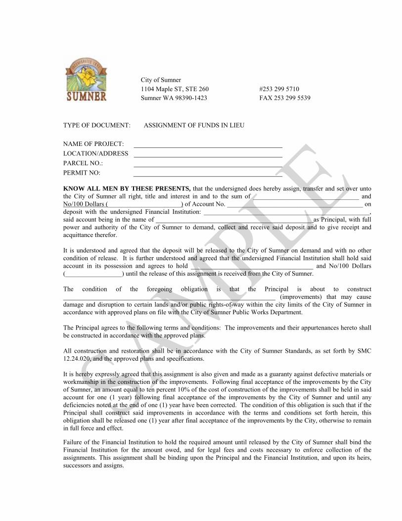
City of Sumner 1104 Maple ST, STE 260 #253 299 5710 Sumner WA 98390-1423 FAX 253 299 5539
TYPE OF DOCUMENT: ASSIGNMENT OF FUNDS IN LIEU NAME OF PROJECT:
LOCATION/ADDRESS
PARCEL NO.:
PERMIT NO: KNOW ALL MEN BY THESE PRESENTS, that the undersigned does hereby assign, transfer and set over unto the City of Sumner all right, title and interest in and to the sum of ________________________________ and No/100 Dollars (______________________) of Account No. _________________________________________ on deposit with the undersigned Financial Institution: __________________________________________________, said account being in the name of _______________________________________________ as Principal, with full power and authority of the City of Sumner to demand, collect and receive said deposit and to give receipt and acquittance therefor. It is understood and agreed that the deposit will be released to the City of Sumner on demand and with no other condition of release. It is further understood and agreed that the undersigned Financial Institution shall hold said account in its possession and agrees to hold _____________________________________ and No/100 Dollars (_________________) until the release of this assignment is received from the City of Sumner. The condition of the foregoing obligation is that the Principal is about to construct ________________________________________________________________ (improvements) that may cause damage and disruption to certain lands and/or public rights-of-way within the city limits of the City of Sumner in accordance with approved plans on file with the City of Sumner Public Works Department. The Principal agrees to the following terms and conditions: The improvements and their appurtenances hereto shall be constructed in accordance with the approved plans. All construction and restoration shall be in accordance with the City of Sumner Standards, as set forth by SMC 12.24.020, and the approved plans and specifications. It is hereby expressly agreed that this assignment is also given and made as a guaranty against defective materials or workmanship in the construction of the improvements. Following final acceptance of the improvements by the City of Sumner, an amount equal to ten percent 10% of the cost of construction of the improvements shall be held in said account for one (1 year) following final acceptance of the improvements by the City of Sumner and until any deficiencies noted at the end of one (1) year have been corrected. The condition of this obligation is such that if the Principal shall construct said improvements in accordance with the terms and conditions set forth herein, this obligation shall be released one (1) year after final acceptance of the improvements by the City, otherwise to remain in full force and effect.
Failure of the Financial Institution to hold the required amount until released by the City of Sumner shall bind the Financial Institution for the amount owed, and for legal fees and costs necessary to enforce collection of the assignments. This assignment shall be binding upon the Principal and the Financial Institution, and upon its heirs, successors and assigns.

City of Sumner Public Works Department-Pam 1104 Maple ST, Suite 260 Sumner WA 98390-1423 253 891 3316
STORMWATER MAINTENANCE & DEFECT BOND
NAME OF PROJECT: BOND NO
LOCATION/ADDRESS
PARCEL NO:
PROJECT NO.: WE, _______________________________________, as Principal, and _______________________________________, a corporation organized and existing under and by virtue of the laws of the State of ______________________________, legally doing business in the State of Washington, as Surety, are held and firmly bound unto the City of Sumner, Pierce County, Washington, as Obligee, in the penal sum of, (20%*???????.00) equals to ?????????????????????and 00/100 Dollars ($????????.00), for the payment of which we firmly bind ourselves, our legal representatives, successors and assigns, jointly and severally. NOW, THEREFORE, THE CONDITIONS OF THIS OBLIGATION are such that after satisfactory completion of the facilities and prior to release of the Performance Bond by the City, Principal shall commence a two (2) year warranty period and satisfactory maintenance period, concurrently of the storm drainage system. The bond is to be used at the discretion of the City Engineer to correct deficiencies in said maintenance affecting public health, safety and welfare, and, to cover the cost of design defects or failures in workmanship of the storm drainage system. SMC 13.48.560 IT IS FURTHER EXPRESSLY UNDERSTOOD THAT: 1. Maintenance shall be performed per the signed Agreement to Maintain Stormwater Facility. 2. Until written release of this obligation by the Obligee, this bond may not be terminated or cancelled by the
Principal or Surety for any reason. 3. Damage from expected usage and damage due to construction activities shall be considered "defects" for
purposes of this bond. 4. In the event of any failure of the improvements to satisfactorily perform or in the event of a defect in the
workmanship or materials, the Principal or Surety shall make prompt and adequate repair to correct the failure or defect. In the event these repairs are not make within 45 days of notice by either the Principal or Surety, the surety shall, upon demand, tender the total bond amount to the Obligee. After making the repairs, the Obligee will return any unexpected funds, without interest, to the Surety.
5. In the event the Obligee determines that repairs must be performed immediately to prevent risk to person and property, the Obligee may make the repairs and the costs of those repairs shall be paid by the Principal or Surety.
6. The Principal shall be obligated to make the repairs described above, which obligation shall not be limited by the amount of this bond.
IN WITNESS THEREOF, the seal and signature of said Principal is hereto affixed and the corporate seal and the name of the said Surety is hereto affixed and attested by its duly authorized Attorney-in-Fact this __________ day of _______________________________, _____________.
PRINCIPAL SURETY
By: By:
Printed Name: Printed Name:
Date: Date:
Mailing Address:
Mailing Address:
Phone # Phone #

City of Sumner Public Works Department-Pam 1104 Maple ST, Suite 260 Sumner WA 98390-1423 253 299 5710
WARRANTY & DEFECT BOND type
NAME OF PROJECT: BOND NO:
LOCATION/ADDRESS
PARCEL NO.:
PERMIT NO: WE, ________________________________, as Principal, and __________________________________, a corporation organized and existing under and by virtue of the laws of the State of ___________________, legally doing business in the State of Washington, as Surety, are held and firmly bound unto the City of Sumner, Pierce County, Washington, as Obligee, in the penal sum of (20%*???????.00) equals to ?????????????????????and 00/100 Dollars ($????????.00), for the payment of which we firmly bind ourselves, our legal representatives, successors and assigns, jointly and severally. WHEREAS, the Principal has completed the project in the City of Sumner, Pierce County, Washington, and the Principal has constructed certain improvements in connection with said project and intends to secure the successful operation of said improvements pursuant to RCW 58.17 and the City of Sumner code. NOW, THEREFORE, THE CONDITIONS OF THIS OBLIGATION are such that if the improvements constructed by the Principal shall successfully operate for a period of two (2) years from the satisfactory completion of the facility or final plat approval, whichever is later, and shall remain free of defect in workmanship and materials for the period, then and in that event, upon written discharge from the Obligee, the obligations of this bond shall be void, otherwise to remain in full force and effect. IT IS FURTHER EXPRESSLY PROVIDED THAT: 1. Until written release of this obligation by the Obligee, this bond may not be terminated or cancelled by the
Principal or Surety for any reason. 2. Damage from expected usage and damage due to construction activities shall be considered "defects" for
purposes of this bond. In the event of any failure of the improvements to satisfactorily perform or in the event of a defect in the workmanship or materials, the Principal or Surety shall make prompt and adequate repair to correct the failure or defect.
3. In the event these repairs are not made within 45 days of notice by either the Principal or Surety, the surety shall, upon demand, tender the total bond amount to the Obligee. After making the repairs, the Obligee will return any unexpected funds, without interest, to the Surety.
4. In the event the Obligee determines that repairs must be performed immediately to prevent risk to person and property, the Obligee may make the repairs and the costs of those repairs shall be paid by the Principal or Surety.
5. The Principal shall be obligated to make the repairs described above, which obligation shall not be limited by the amount of this bond.
IN WITNESS THEREOF, the seal and signature of said Principal is hereto affixed and the corporate seal and the name of the said Surety is hereto affixed and attested by its duly authorized Attorney-in-Fact this __________ day of __________________________, _______________.
PRINCIPAL SURETY
By: By:
Printed Name: Printed Name:
Date: Date:
Mailing Address:
Mailing Address:
Phone #
Phone #

City of Sumner Public Works Department-Pam 1104 Maple ST, Suite 260 Sumner WA 98390-1423 253 299 5710
MAINTENANCE LANDSCAPE BOND 18.41.090
NAME OF PROJECT: BOND NO:
LOCATION/ADDRESS
PARCEL NO.:
PERMIT NO: WE, ______________________________________________________________, as Principal, and ___________________________________________________, a corporation organized and existing under and by virtue of the laws of the State of _________________________________, legally doing business in the State of Washington, as Surety, are held and firmly bound unto the City of Sumner, Pierce County, Washington, as Obligee, in the penal sum of (50%*???????.00) equals to ???????????????????? and 00/100 Dollars ($????????.00), for the payment of which we firmly bind ourselves, our legal representatives, successors and assigns, jointly and severally. WHEREAS, the Principal has completed the project which includes site landscaping, located at the project mentioned above, in the City of Sumner, Pierce County, Washington, and the Principal has constructed certain improvements in connection with said project and the maintenance guarantee shall include maintenance during the guarantee period and replacement of dead or unhealthy plants at the conclusion of the guarantee period. NOW, THEREFORE, THE CONDITIONS OF THIS OBLIGATION are such that if the improvements constructed by the Principal shall successfully operate for a period of two (2) year from the satisfactory completion of the facility or final plat approval, whichever is later, and shall remain free of defect in workmanship and materials for the period, then this obligation shall be null and void, otherwise to remain in full force and effect. IT IS FURTHER EXPRESSLY PROVIDED THAT: Until written release of this obligation by the Obligee, this bond may not be terminated or cancelled by the Principal or Surety for any reason. Damage from expected usage and damage due to construction activities shall be considered "defects" for purposes of this bond. In the event of any failure of the improvements to satisfactorily perform or in the event of a defect in the workmanship or materials, the Principal or Surety shall make prompt and adequate repair to correct the failure or defect. In the event these repairs are not made within 45 days of notice by either the Principal or Surety, the surety shall, upon demand, tender the total bond amount to the Obligee. After making the repairs, the Obligee will return any unexpected funds, without interest, to the Surety. In the event the Obligee determines that repairs must be performed immediately to prevent risk to person and property, the Obligee may make the repairs and the costs of those repairs shall be paid by the Principal or Surety. The Principal shall be obligated to make the repairs described above, which obligation shall not be limited by the amount of this bond. IN WITNESS THEREOF, the seal and signature of said Principal is hereto affixed and the corporate seal and the name of the said Surety is hereto affixed and attested by its duly authorized Attorney-in-Fact this __________ day of __________________________, _______________.
PRINCIPAL SURETY
By: By:
Printed Name: Printed Name:
Date: Date:
Mailing Address:
Mailing Address:
Phone # Phone #

Development Specifications and Standard Details
APPENDIX E
Final Cost Data, Inventory Forms, and Bill of Sale

RETURN TO: City of Sumner Public Works Department – Pam 1104 Maple Street, Suite 260 Sumner WA 98390-1423
Please make no mark in the margin space - Reserved for County Auditor's use only.
TYPE OF DOCUMENT: Bill of Sale (corporation) GRANTOR(S): GRANTEE: City of Sumner, a Municipal Corporation ABBREVIATED LEGAL DESCRIPTION: Legal Description is on Page 1 or Exhibit A of document ABBREVIATED LEGAL: ASSESSOR TAXPARCEL I.D. NUMBERS: NAME OF PROJECT ADDRESS OF PROJECT: PROJECT No:
The Grantor(s), lawful owners of the goods referenced herein, for and in consideration of mutual benefits, do by these presents transfer, sell, assign, and deliver all of their right, title, and interest unto the said Grantee, the personal property described following: LEGAL DESCRIPTION: on page 1 or Exhibit A of this document PERSONAL PROPERTY DESCRIPTION: on page 1 or Exhibit B of this document By this conveyance, Grantor will warrant and defend the sale hereby made unto the Grantee against all and every person or persons, whomsoever, lawfully claiming or to claim the same. This conveyance shall bind the heirs, executors, administrators and assigns forever.
(Notary Acknowledgement on Next Page)

PERSONAL PROPERTY DESCRIPTION TYPE OF DOCUMENT: Bill of Sale GRANTOR(S): ABBREVIATED LEGAL: ASSESSOR TAXPARCEL I.D. NUMBERS:
NAME OF PROJECT ADDRESS OF PROJECT: PROJECT No: Per the request of the City of Sumner the following information is furnished concerning final costs for improvements installed that are turned over to the City for the above referenced project.
Description Unit Unit cost Plan quantity Total
WATER 3/4 Water service meter Ea 1 Water service meter Ea 1.5 Water service meter Ea 2 Water service meter Ea Fire hydrant assembly Lf 2 Blow off assembly Ea 8 Gate valve Ea 10 Butterfly valve Ea 12 Butterfly valve Ea Air relief valve Ea 8 Reduced pressure assembly Ea 8 DIP Lf 10 DIP Lf 12 DIP Lf 16 DIP Lf <2 Double check assembly Ea <2 Reduced pressure assembly Ea >2 Double detector check Ea Pressure reducing station Ea
Includes Engineering and sales Tax if applicable
TOTAL COST FOR WATER SYSTEM

RETURN TO: City of Sumner Public Works Department – Pam 1104 Maple Street, Suite 260 Sumner WA 98390-1423
Please make no mark in the margin space - Reserved for County Auditor's use only.
TYPE OF DOCUMENT: Bill of Sale (limited liability partnership) GRANTOR(S): GRANTEE: City of Sumner, a Municipal Corporation ABBREVIATED LEGAL DESCRIPTION: Legal Description is on Page 1 or Exhibit A of document ABBREVIATED LEGAL: ASSESSOR TAXPARCEL I.D. NUMBERS: NAME OF PROJECT ADDRESS OF PROJECT: PROJECT No:
The Grantor(s), lawful owners of the goods referenced herein, for and in consideration of mutual benefits, do by these presents transfer, sell, assign, and deliver all of their right, title, and interest unto the said Grantee, the personal property described following: LEGAL DESCRIPTION: on page 1 or Exhibit A of this document PERSONAL PROPERTY DESCRIPTION: on page 1 or Exhibit B of this document By this conveyance, Grantor will warrant and defend the sale hereby made unto the Grantee against all and every person or persons, whomsoever, lawfully claiming or to claim the same. This conveyance shall bind the heirs, executors, administrators and assigns forever.
(Notary Acknowledgement on Next Page)

RETURN TO: City of Sumner Public Works Department – Pam 1104 Maple Street, Suite 260 Sumner WA 98390-1423
Please make no mark in the margin space - Reserved for County Auditor's use only.
TYPE OF DOCUMENT: Bill of Sale (individual) GRANTOR(S): GRANTEE: City of Sumner, a Municipal Corporation ABBREVIATED LEGAL DESCRIPTION: Legal Description is on Page 1 or Exhibit A of document ABBREVIATED LEGAL: ASSESSOR TAXPARCEL I.D. NUMBERS: NAME OF PROJECT ADDRESS OF PROJECT: PROJECT No:
The Grantor(s), lawful owners of the goods referenced herein, for and in consideration of mutual benefits, do by these presents transfer, sell, assign, and deliver all of their right, title, and interest unto the said Grantee, the personal property described following: LEGAL DESCRIPTION: on page 1 or Exhibit A of this document PERSONAL PROPERTY DESCRIPTION: on page 1 or Exhibit B of this document By this conveyance, Grantor will warrant and defend the sale hereby made unto the Grantee against all and every person or persons, whomsoever, lawfully claiming or to claim the same. This conveyance shall bind the heirs, executors, administrators and assigns forever.
(Notary Acknowledgement on Next Page)

Development Specifications and Standard Details
APPENDIX F
Rainfall Intensity Graph

Development Specifications and Standard Details
APPENDIX G
Single Family Residential Infiltration System Design Guide

CITY OF SUMNER
14
Single Family Residential (SFR) Infiltration, Dispersion, and Bioretention Systems
Application Work Sheets City of Sumner
Building Permit No.______________________ Parcel No.______________________________
Site Address: __________________________________________________________________
Date: __________________________________ Prepared by: ___________________________________________________________________ Contact Phone #:_________________________ E-mail address: __________________________
Engineering stamp, signature and date (if prepared by a Professional Engineer licensed by the State of Washington): This infiltration application is intended to assist you in designing a single family residential infiltration system for an existing lot. It provides a simplified approach to designing an infiltration system. For a more detailed description, refer to the 2005 Stormwater Management Manual for Western Washington, found online at the website listed below. Roof downspout controls are simple pre-engineered designs for infiltrating or dispersing runoff from non-pollution generating roof areas. Downspout infiltration is a method that may be used in areas where the soils are determined to be suitable. The following are typical methods used and allowed to manage the runoff from single family residential home construction sites. This worksheet is not applicable to SFR units as part of a short plat, plat, planned unit development, or subdivision.
Infiltration Methods:

CITY OF SUMNER
15
Downspout infiltration systems Downspout dispersion systems Bioretention areas (Rain Gardens)
For more information, refer to the following: • 2005 Stormwater Management Manual for Western Washington Volume III, Chapter 3; • 2005 Low Impact Development Technical Guidance Manual for Puget Sound; and, • 2007 Rain Garden Handbook for Western Washington Homeowners. These references can be found online at: http://www.ecy.wa.gov/programs/wq/stormwater/manual.html http://www.psp.wa.gov/downloads/lid/lid_manual2005.pdf http://www.pierce.wsu.edu/lid/raingarden/raingarden_handbook.pdf
Site Location
One of the first steps in siting and designing infiltration facilities is to conduct a characterization study that includes the following:
1. Subsurface explorations (test holes or test pits) to a depth below the base of the infiltration facility of at least 5 times the maximum design depth of ponded water proposed for the infiltration facility,
2. Continuous sampling (representative samples from each soil type and/or unit within the
infiltration receptor) to a depth below the base of the infiltration facility of 2.5 times the maximum design ponded water depth, but not less than 6 feet.
a. For basins, at least one test pit or test hole per 5,000 ft2 of basin infiltrating surface (in no
case less than two per basin). b. For trenches, at least one test pit or test hole per 50 feet of trench length (in no case less
than two per trench).
3. Prepare detailed logs for each test pit or test hole and a map showing the location of the test pits or test holes. Soil logs must include at a minimum, depth of pit or hole, soil descriptions, depth to water, presence of stratification (note: Logs must substantiate whether stratification does or does

CITY OF SUMNER
16
not exist. The licensed professional may consider additional methods of analysis to substantiate the presence of stratification that will significantly impact the design of the infiltration facility).
4. Infiltration rates can be determined using either a correlation to grain size distribution from soil
samples, textural analysis, or by in-situ field measurements.
5. Unless otherwise required by the City of Sumner, the vertical distance between the bottom of the system and the seasonal high-water mark, bedrock (hardpan) or other low permeability layer shall be 1-foot minimum provided that the contributing area does not exceed the following:
• 5,000 square feet of pollution-generating impervious surface; or • 10,000 square feet of impervious area; or • ¾ acre of lawn and landscape.
6. A site layout shall be attached to this application that shows the following information at a
minimum. The site layout shall show dimensions and/or be drawn to scale.
• Location and layout of proposed improvements and all other areas proposed to drain to the stormwater facility;
• Location of critical areas and buffers; • Location of wells and septic systems; • Property boundaries; • Constructed off-site improvements within 10-feet of the proposed facility; • Proposed drainage paths and dimensions for dispersion systems; • Location and layout of proposed stormwater facility; • Location of soil testing locations; • Location of groundwater protection areas and/or 1, 5 and 10-year time of travel zones for
municipal well protection areas; and, • Contours

CITY OF SUMNER
17

CITY OF SUMNER
18
Downspout Infiltration Systems
Downspout infiltration systems are trenches intended only for use in infiltrating runoff from roof downspout drains. Refer to 2005 SMMWW Volume III, Chapter 3 for more information on infiltration systems. Design Criteria for Infiltration Trenches Figure 3.2 shows a typical downspout infiltration trench system, and Figure 3.3 presents an alternative infiltration trench system for sites with coarse sand and cobble soils. These systems are designed as specified below. General
1. The following minimum lengths (linear feet) per 1,000 square feet of roof area based on soil type may be used for sizing downspout infiltration trenches.
Coarse sands and cobbles 20LF Medium sand 30LF Fine sand, loamy sand 75LF Sandy loam 125LF Loam 190LF
2. Maximum length of trench must not exceed 100 feet from the inlet sump. 3. Minimum spacing between trench centerlines must be 6 feet.
4. Filter fabric must be placed over the drain rock as shown on Figure 3.2 prior to backfilling.
5. Infiltration trenches may be placed in fill material if the fill is placed and compacted under the
direct supervision of a geotechnical engineer or professional civil engineer with geotechnical expertise, and if the measured infiltration rate is at least 8 inches per hour. Trench length in fill must be 60 linear feet per 1,000 square feet of roof area.
6. Infiltration trenches should not be built on slopes steeper than 25 percent (4:1). A geotechnical
analysis and report may be required on slopes over 15 percent or if located within 200 feet of the top of steep slope or landslide hazard area.
7. Trenches may be located under pavement if a small yard drain or catch basin with grate cover is
placed at the end of the trench pipe such that overflow would occur out of the catch basin at an elevation at least one foot below that of the pavement, and in a location which can accommodate the overflow without creating a significant adverse impact to downhill properties or drainage systems. This is intended to prevent saturation of the pavement in the event of a system failure.

CITY OF SUMNER
19

CITY OF SUMNER
20
Setbacks for Infiltration Trenches The City of Sumner requires specific setbacks for sites with steep slopes, land slide areas, open water features, springs, wells, and septic tank drain fields. Adequate room for maintenance access and equipment should also be considered when designing your facility. Setback regulations for the City are as follows:
A. All infiltration systems should be at least 10 feet from any structure or property line.
B. For sites with septic systems, infiltration systems must be down gradient of the drain field unless the site topography clearly prohibits subsurface flows from intersecting the drain field. Stormwater infiltration facilities shall be set back at least 10 feet from septic tanks and septic drain fields.
C. Infiltration systems shall be setback from sensitive areas, steep slopes, landslide hazard areas,
and erosion hazard areas as governed by Sumner Municipal Code Title 16. Runoff discharged

CITY OF SUMNER
21
near landslide hazard areas must be evaluated by a geotechnical engineer or qualified geologist licensed in Washington State. The discharge point shall not be placed on or above slopes greater than 25% (4:1) or above erosion hazard areas without evaluation by a geotechnical engineer or qualified geologist and City approval. All infiltration systems must be at least 50 feet from the top of any sensitive area steep slope. This setback may be reduced to 15 feet based on a geotechnical evaluation, but in no instances may it be less than the buffer width.
D. Stormwater infiltration facilities shall be set back at least 100 feet from drinking water wells
and springs used for public drinking water supplies. Additional measures may be necessary to comply with Health Department requirements for well head protection (Washington Wellhead Protection Program, DOH, and Publication 331-018.

CITY OF SUMNER
22
Infiltration Trench Design DESCRIPTION OF PROJECT: _______________________________________________________________________ _______________________________________________________________________ _______________________________________________________________________ _______________________________________________________________________ DESIGN: Step 1. Determine the roof and driveway areas and check the soil group/infiltration rate
design is based on. Check the soil group that applies to your site. Building Area: _______________ sq. ft. Roof Overhang: _________ feet Roof Area: ________________ sq. ft. (5,000 square foot maximum) Driveway: ________________ sq. ft. (5,000 square foot maximum)
Saturated Infiltration Rate: � 60 inches/hour � 12 inches/hour � 4 inches/hour � 2 inches/hour � 1 inches/hour * If less than 1 inch/hour, professional Engineer required. Step 2. Select a trench depth between 1 and 4 feet.
Roof trench depth = __________________ ft. Driveway trench depth = ______________ ft.
Step 3. Select the correct trench bottom multiplier using the Sizing Table.
Roof multiplier = __________________ Driveway multiplier = ______________
Step 4. Select a trench width, the wider the trench (4 ft. max), the shorter the trench
length. Roof trench width = __________________ ft. (2’ min. - 4’ max.) Driveway trench width = ______________ ft. (2’ min. – 4’ max.)
Step 5. Calculate the required trench length. (Maximum trench length must not exceed

CITY OF SUMNER
23
100 feet from an inlet sump)
Trench length of the roof = roof area (Step 1) times the trench bottom multiplier (Step 3) divided by the trench width (Step 4).
__________ sq. ft. x __________ (multiplier) ⁄ __________ ft. = __________ ft. Trench length of the driveway = driveway area (Step 1) times the trench bottom multiplier (Step 3) divided by the trench width (Step 4). ___________ sq. ft. x __________ (multiplier) ⁄ _________ ft. = ___________ ft. Step 6. Summarize the trench dimensions: Roof: ________________ ft. deep x ___________ ft. wide x ____________ ft. long Driveway: ____________ ft. deep x ____________ ft. wide x ____________ ft. long Step 7 (Optional). For a combined roof and driveway trench (5,000 square foot
maximum), summarize the trench dimensions:
Roof & Driveway: ___________ ft. deep x ___________ ft. wide x __________ ft. long The above design meets the minimum requirements for stormwater control in accordance with the 2005 Stormwater Management Manual for Western Washington. _____________________________________ ___________________________ Prepared by Date _____________________________________ ___________________________ Signature Registration No. (if prepared by Professional Engineer)
Sign, date, and stamp

CITY OF SUMNER
24
Sizing Table Saturated Infiltration Rate Depth (ft.) Trench Bottom Multiplier
60 inches/hour
2’ 0.024 2.5’ 0.022 3’ 0.019
3.5’ 0.018 4’ 0.017
4.5’ 0.016 5’ 0.015
12 inches/hour
2’ 0.058 2.5’ 0.052 3’ 0.046
3.5’ 0.044 4’ 0.040
4.5’ 0.038 5’ 0.036
4 inches/hour
2’ 0.101 2.5’ 0.090 3’ 0.080
3.5’ 0.076 4’ 0.072
4.5’ 0.066 5’ 0.063
2 inches/hour
2’ 0.144 2.5’ 0.130 3’ 0.114
3.5’ 0.108 4’ 0.102
4.5’ 0.094 5’ 0.090
1 inch/hour
2’ 0.206 2.5’ 0.184 3’ 0.163
3.5’ 0.153 4’ 0.146
4.5’ 0.135 5’ 0.129

CITY OF SUMNER
25
Downspout Dispersion Systems
Downspout dispersion systems are splash blocks or gravel-filled trenches, which serve to spread roof runoff over vegetated pervious areas. Dispersion attenuates peak flows by slowing entry of the runoff into the conveyance system, allows for some infiltration, and provides some water quality benefits. Downspout dispersion may be used for a SFR unit, if the following criteria are met:
I. Lots greater than or equal to 22,000 square feet where downspout infiltration is not being provided according to the requirements in design criteria below can be met.
II. Lots smaller than 22,000 square feet where soils are not suitable for downspout infiltration and
where the design criteria below can be met.

CITY OF SUMNER
26
General
1. Downspout trenches designed as shown in Figure 3.5 should be used for all downspout dispersion applications except where splash blocks are allowed below.
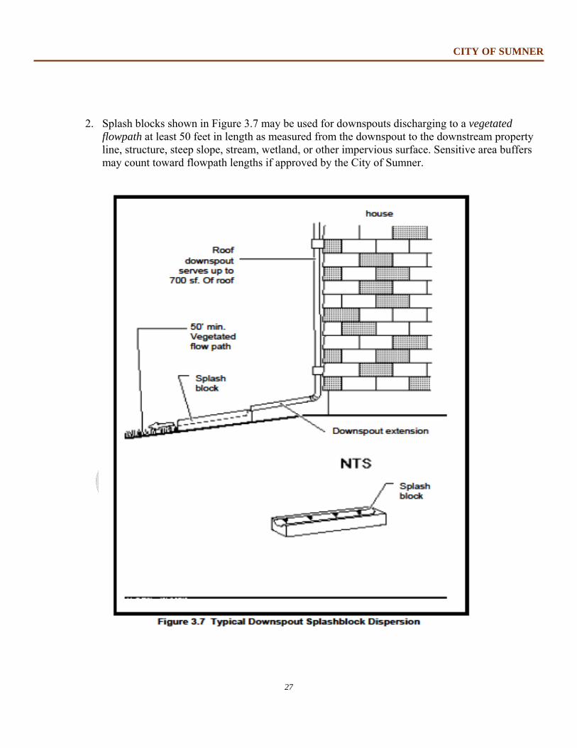
CITY OF SUMNER
27
2. Splash blocks shown in Figure 3.7 may be used for downspouts discharging to a vegetated
flowpath at least 50 feet in length as measured from the downspout to the downstream property line, structure, steep slope, stream, wetland, or other impervious surface. Sensitive area buffers may count toward flowpath lengths if approved by the City of Sumner.

CITY OF SUMNER
28
3. For sites with septic systems, the discharge point of all dispersion systems must be down gradient of the drain field. This requirement may be waived if site topography clearly prohibits flows from intersecting the drain field.
Design Criteria for Dispersion Trenches
1. A vegetated flowpath of at least 25 feet in length must be maintained between the outlet of the trench and any property line, structure, stream, wetland, or impervious surface. A vegetated flowpath of at least 50 feet in length must be maintained between the outlet of the trench and any steep slope. Sensitive area buffers may count towards flowpath lengths if approved by City of Sumner.
2. Trenches serving up to 700 square feet of roof area may be simple 10-foot-long by 2-foot wide
gravel filled trenches as shown in Figure 3.5. For roof areas larger than 700 square feet, a dispersion trench with notched grade board as shown in Figure 3.6 (on next page) may be used as approved by the City. The total length of this design must not exceed 50 feet and must provide at least 10 feet of trench per 700 square feet of roof area.
3. A setback of at least 5 feet should be maintained between any edge of the trench and any
structure or property line. 4. No erosion or flooding of downstream properties may result.
5. Runoff discharged towards landslide hazard areas must be evaluated by a geotechnical engineer
or a licensed geologist, hydrogeologist, or engineering geologist. The discharge point may not be placed on or above slopes greater than 20% or above erosion hazard areas without evaluation by a geotechnical engineer or qualified geologist and approval by the City.

CITY OF SUMNER
29

CITY OF SUMNER
30
Design Criteria for Splashblocks A typical downspout splash block is shown in Figure 3.7. In general, if the ground is sloped away from the foundation and there is adequate vegetation and area for effective dispersion, splashblocks will adequately disperse storm runoff. If the ground is fairly level, if the structure includes a basement, or if foundation drains are proposed, splashblocks with downspout extensions may be required because the discharge point is moved away from the foundation. Downspout extensions can include piping to a splashblock/discharge point a considerable distance from the downspout, as long as the runoff can travel through a well-vegetated area as described below.
1. A vegetated flowpath of at least 50 feet should be maintained between the discharge point and any property line, structure, steep slope, stream, wetland, lake, or other impervious surface. Sensitive area buffers may count toward flowpath lengths.
2. A maximum of 700 square feet of roof area may drain to each splashblock.
3. A splashblock or a pad of crushed rock (2 feet wide by 3 feet long by 6 inches deep) should be
placed at each downspout discharge point.
4. No erosion or flooding of downstream properties may result.
5. Runoff discharged towards landslide hazard areas must be evaluated by a professional engineer with geotechnical expertise or a qualified geologist. Splashblocks may not be placed on or above slopes greater than 20% or above erosion hazard areas without evaluation by a professional engineer with geotechnical expertise or a licensed geologist, hydrogeologist, or engineering geologist, and jurisdiction approval.
6. For sites with septic systems, the discharge point must be downslope of the primary and reserve
drainfield areas. This requirement may be waived if site topography clearly prohibits flows from intersecting the drainfield or where site conditions, such as soil permeability and distance between systems, indicate that this is unnecessary.

CITY OF SUMNER
31
Bioretention areas (Rain Gardens)
Bioretention areas are small vegetated areas or swales designed to store and infiltrate stormwater runoff from impervious surfaces. They are designed with a layer of porous soils that have a capacity to store water in areas with lower infiltration rates. The plants, shrubs, and trees control erosion and provide habitat. Another additional benefit to installing a rain garden is the ability to recharge the local groundwater level.
General
1. Soil depth should be a minimum of 12 inches to provide acceptable minimum pollutant
attenuation and good growing conditions for selecting plants. Ponding depth above the soil is typically 6- to 12-inches.
2. The texture of the bioretention soil mix should be loamy sand. The final soil mixture shall meet
the following requirements:
a) Clay content should be less than 5 percent. b) (Including compost and soil) Should have a minimum short-term hydraulic conductivity of 1.0 inches
/hour. c) Should have a minimum organic content of approximately 10 percent by dry weight.
3. The pH for the soil mixture should be between 5.5 and 7.0. 4. Biorentention areas can be designed with or without a mulch layer.
5. Compost in bioretention facilities shall meet the following requirements:
a) Material must be composted in a facility that is in compliance with WAC chapter 173-350-220 and meet the material requirements of WAC 173-350-220. This code is available online at http://www.ecy.wa.gov/programs/swfa/facilities/350.html.
b) pH between 5.5 and 7.0. c) Carbon nitrogen ratio between 20:1 and 35:1 (35:1 CN ratio recommended for native
plants). d) Organic matter content should be between 35% and 65%. e) Moisture content range between 35- and 50-percent.
6. Plants should be tolerant of ponding fluctuations and saturated soil conditions and drought during the summer months. Predominant plant material should adapt to stresses associated with wet and dry conditions. Some common plant selections are as follows. Other plants may be appropriate as identified in the Rain Garden Handbook for Western Washington Homeowners.

CITY OF SUMNER
32
Sunny / Partly Sunny location Plants for basin Red-twig dogwood Yellow dogwood Clustered wild rose Slough sedge Dagger –leaf rush Cascara Vine Maple Plants for lower sidewalls Coralberry Tall Oregon-grape Western Columbine Douglas’ aster Common Camas Plants for upper sidewalls Lavender Sunrose Red-flowering Currant Fountain Grass
Shady / Partly Shady
Plants for basin Salmonberry Slough Sedge Moor Grass Lady Fern Deer Fern Stink Currant Plants for lower sidewalls Snowberry Wild Ginger Sword Fern Youth-on-age Foamflower Plants for upper sidewalls Salal Cascade Oregon-grape Creeping Mahonia
Evergreen Huckleberry

7. Maximum ponding depth of 12” recommended.
8. Maximum surface pool drawdown time of 24 hours is recommended. 9. If the slope of the land is greater then 15% where the rain garden is to be installed, consult
with a geotechnical engineer or geologist to evaluate the site for potential problems. 10. Excavation is not allowed during wet or saturated conditions and no heavy equipment is
allowed on the bottom of the bioretention facility. The preferred time to install a rain garden is typically in the spring or fall when the ground is damp but not muddy.
Figure 4: Bioretention Facility Design
Design Criteria for Pothole Bioretention Cells
The rain garden is represented as a pond with a steady-state infiltration rate. The pond volume is a combination of the above ground volume available for water storage and the volume available for storage within the imported soil. The above ground volume is the size of the “pothole” that accommodates standing water. A minimum ponding depth of 6- to 12-inches is recommended. The soil storage volume is determined by multiplying the volume occupied by the imported soil by the soil’s percent porosity. Use 40 percent porosity for bioretention planting mix soils. Sidewalls should not be steeper than 2 horizontal to 1 vertical. Design 1. Calculate (add together) the impervious surfaces on the existing property contributing to the rain
garden, including: roof area, driveway/parking lot etc. This may or may not include all or part of a roof and/or driveway area.
Total Impervious Surface Area: _________________ ft2.
2. Calculate the area of the rain garden. (Depth is constant at 18 inches).

City of Sumner Appendix G Development Specifications and Standard Details G-1 March 2011 Appendix G – Estimated Daily Sewer Flows
Dimensions: Length__________ x Width___________ = Area_____________ft2.
3. Divide the area of the rain garden by the impervious surface area to get a percentage.
Area Rain Garden ______________ ft2. x 100 = ___________% Total Imp. Surface ft2.
4. Utilize Table 1 to determine if rain garden is dimensioned appropriately to adequately infiltrate
100% of the runoff. Look at the size of your rain garden in column 1 (the number you calculated in part 3 above) and based on the type of soil, columns 2 and 3 will give you the percentage of water the garden will hold/infiltrate. If the volume of water held is below 100% adjust the rain garden dimensions until 100% “water held” is reached.
Table 1: Annual volume of water held in a rain garden with 12 inches of rain garden soil mix and a 6-inch ponding depth (18 inches total). Size of rain garden (as a percent of impervious area and measured in square feet)
Annual volume of water held in a rain garden for poor-draining soils
(0.25 to 0.50 inches/hour)
Annual volume of water held in rain garden for well-draining soils
(>0.5 inches/hour)
10% 70% 99% 20% 90% 100% 50% 99% 100% 80% 100% 100%
If the depth of the rain garden is increased to 30 inches (24 inches of rain garden soil mix and a 6-inch ponding depth) on poor-draining soils, then you can reduce the square foot area by 5% and hold the same amount of water. On well-draining soils depth does not significantly increase how much water the rain garden can hold. Source: Rain Garden Handbook for Western Washington Homeowners.
5. Inlets and overflows should be lined with rock to prevent erosion. 6. Runoff can be directed into the rain garden through a swale lined with rock or a pipe. If slope
into the garden is over 5% place check dams in swale or pad of rock where it enters the ponding area.
7. An overflow should extend about 4 feet outside the rain garden and be directed towards storm
drain or disperse into landscape.
8. If the area for rain garden installation is sloped more than 5% then one approach is to dig the downhill end of the rain garden to its normal depth of 18-30 inches with a flat bottom. This would increase the depth of the uphill side thus making it greater then the downhill depth of the

City of Sumner Appendix G Development Specifications and Standard Details G-2 March 2011 Appendix G – Estimated Daily Sewer Flows
rain garden. The second approach is to take the dirt removed from the uphill end and build a berm on the downhill end.
a) The bottom of the rain garden should be flat and level. b) The soils to build the berm should be compacted every few inches of soil added. c) Build the berm to the level of the uphill surface. Use a string, stake and level to measure
correct height. d) The berm should be at least 24 inches wide and have mild sloping sides. e) If the overflow is located on the berm, cover the overflow of the berm with rock to prevent
erosion.
9. If a soil depth other than 12-inches is used, a ponding depth other than 6-inches is used, or a rain-garden-to-impervious-cover ratio other than 80-percent is used, the rain garden must be sized using the Western Washington Hydrology Model version 3 (WWHM3). If pervious areas are routed to the rain garden, the rain garden must be sized using WWHM3. If a WWHM3 analysis is required for the project, this application for a Single Family Residential Infiltration System is not applicable.

Development Specifications and Standard Details
APPENDIX H
Sewer Agreement

RETURN TO: City of Sumner Public Works Department - Pam 1104 Maple Street, Suite 260 Sumner WA 98390-1423
Please make no mark in the margin space - Reserved for County Auditor's use only.
TYPE OF DOCUMENT: SMC 13.60.390 Sewer Agreement to Maintain: corporation FOG Control Program Grease Trap Oil/Separator Grease Interceptor PROPERTY OWNER(S): ABBREVIATED LEGAL DESCRIPTION: ASSESSOR TAXPARCEL I.D. No.: NAME OF PROJECT BUSINESS ADDRESS PROJECT No.: THIS AGREEMENT made and entered into this ______ day of _______________, 20___, by and between the CITY OF SUMNER, a municipal corporation hereinafter referred to as "City", and CORPORATION NAME, (hereinafter referred to as "Owner"). WHEREAS, this agreement contains specific provisions with respect to maintenance of the sewer facilities and use of pollution source control (BMPs), provided in Ordinance No. 2077 SMC 13.16.390; and WHEREAS, Owner owns the following-described real property situated in Pierce County, State of Washington, as set forth in Exhibit ‘A’, which is attached hereto and made a part hereof; and WHEREAS, Owner has installed improvements on the above-described real property; now, therefore, for and in consideration of the mutual benefits to be derived therefrom, it is mutually agreed as follows: C. City and Owner enter into this agreement in order to further the goals of City to insure the protection and
enhancement of City's sewer resources. The responsibilities of each party to this agreement are identified below:
1. Owner shall:
a. Implement the sewer maintenance program included herein as Exhibit "1". b. The maintenance records shall be kept a minimum of three years and provided to the city upon request
at the Owner's business address listed above. c. Notify the City of business address changes. d. The annual report shall catalog the checklist(s) in Exhibit "1" to show the action taken, who took it,
when it was done, how it was done, and any problems encountered or follow-up actions recommended. Maintenance items ("problems") listed in Exhibit "1" shall be inspected as necessary. These completed checklist(s) would then comprise the annual report.
e. Submit the annual report on or before March 15th of each calendar year.

2. City shall: a. Provide technical assistance to Owner in support of its operation and maintenance activities at no
charge to Owner b. Review the annual report and visit the site to discuss performance with Owner and if necessary
consider reasonable modifications. B. Remedies:
4. If City determines that maintenance or repair work is required to be done to the facility existing on Owner's
property, the Director of the Department of Public Works shall give the owner of the property notice of the specific maintenance and/or repair required. The Director shall set a reasonable time in which such work is to be completed by the persons who were given notice. If the above required maintenance and/or repair is not completed within the time set by the Director, written notice will be sent to the owner of the property stating City's intention to discontinue water service.
5. If at any time City determines that the existing system creates any eminent threat to public health or
welfare, the Director may take immediate measures to remedy said threat. Under such circumstances no notice to the persons listed in B.1 above shall be required, but the City shall give the Owner immediate notice of the remedial measures so taken
6. The persons listed in B.1 above shall assume all responsibility for the cost of any maintenance and for
repairs to the sewer facility deemed to be caused by B.1. Such responsibility shall include reimbursement to City within thirty (30) days of the receipt of the invoice for any such work performed. Overdue payments will require payment of interest at the current legal rate for liquidated judgments. If legal action ensues, any costs or fees incurred by City will be borne by the parties responsible for said reimbursements.
7. In the event Owner of the property fails to pay City within thirty (30) days from the date that the costs were
incurred, City shall have the right to file a lien against the real property for all charges and expenses incurred. A lien specifying the expenses incurred and giving a legal description of the premises sought to be charged shall be filed with the County Auditor within ninety (90) days from the date of the completion of the work. The same may at any time thereafter be collected in the manner provided for foreclosure of mechanic's liens under the laws of the State of Washington.
C. Intent:
1. This agreement is intended to protect the public sanitary sewer system, the persons listed in B.1 above, and to benefit all the citizens of the City. It shall run with the land and be binding on all parties having or acquiring from Owner or their successors, any right, title or interest in the property or any part thereof, as well as their title, or interest in the property or any part thereof, as well as their heirs, successors and assigns. They shall inure to the benefit of each present or future successor in interest of said property or any part thereof, or interest therein, and to the benefit of all citizens of City.
(Notary Acknowledgement on Next Page)

IN WITNESS WHEREOF, said Grantor has caused this instrument to be executed this _________day of _____________________ , 20 ___ OWNER SIGNATURE:
By: By:
Its: Its:
STATE OF WASHINGTION ) ) SS COUNTY OF PIERCE )
On this __________________ day of _______________________, 20___, before me, the undersigned, a Notary Public in and for the State of Washington, duly commissioned and sworn personally appeared ________________________________________, to me proven to be the individual described in and who executed the foregoing instrument for himself and acknowledged that he signed the same as his free and voluntary act and deed for himself and also as his free and voluntary act and deed as of said CORPORATION, for uses and purposes therein mentioned, and on oath stated that he was authorized to execute the said instrument. IN WITNESS WHEREOF, I have hereunto set my hand and official seal the day and year first above written.
Printed Name: NOTARY PUBLIC in and for the State
Washington, residing at My Commission Expires:

CITY OF SUMNER:
By: By:
David L. Enslow Mayor Diane L. Supler City Administrator
STATE OF WASHINGTION ) ) SS COUNTY OF PIERCE )
On this ____________________ day of ______________________________, 20___, before me, the undersigned, a Notary Public in the State of Washington, duly commissioned and sworn, personally appeared David L. Enslow and Diane L. Supler, representing themselves as Mayor and City Administrator, respectively, of the City of Sumner, the municipal corporation that executed the foregoing instrument, and acknowledged the instrument to be the free and voluntary act and deed of said municipal corporation for the uses and purposes therein mentioned, and on oath stated that they are authorized to execute the same. IN WITNESS WHEREOF, I have hereunto set my hand and official seal the day and year first above written.
Printed Name:
NOTARY PUBLIC in and for the State
Washington, residing at My Commission Expires:
Approved to Form: ATTEST:
By: By:
Brett Vinson City Attorney Terri Berry City Clerk
Approved By:
William L. Pugh, Public Works Director TYPE OF DOCUMENT: Sewer Agreement to Maintain: Grease Trap / Oil/Separator Grease Interceptor PROPERTY OWNER(S): ASSESSOR TAXPARCEL I.D. No.: NAME OF PROJECT BUSINESS ADDRESS PROJECT No.:

EXHIBIT ‘A’ – SEWER MAINTENANCE AGREEMENT Legal Description

EXHIBIT 1: MAINTENANCE REPORT - COVER SHEET
(Please provide the following information with your annual report) TYPE OF DOCUMENT: Sewer Agreement to Maintain: FOG Control Program Grease Trap Oil/Separator Grease Interceptor ASSESSOR TAXPARCEL I.D. No.: NAME OF PROJECT ADDRESS OF SITE (REQUIRED) PROJECT No.: GT ###### Inspection Period: ANNUALLY by March 15 Date Inspected:
On-site Contact Name (print) (REQUIRED)
Site Contact Mailing Address:
Site Contact Telephone number: (REQUIRED)
Site Contact email address:
City inspection signature:
Location of device:

MAINTENANCE REPORT
DATE GT # Grease Trap Oil/Separator Grease Interceptor SMC 13.16.480 B. 1 / every 90 days serviced + emptied SITE ASSESSMENT □ Condition of grease trap line: Pass □ Fail □ □ Depth of grease: □ Re-inspection date: □ Grease in effluent: Yes □ No □□ Certificate of last pump date: □ «GT_last_date» □ Pumping/Cleaning Frequency «Frequency» □ □ □ ACTION REQUIRED:
COMMENTS:
TYPE OF GREASE TRAP: # of Chambers: Measurements:Location:
CHAMBER DEPTH OF CHAMBER
SCUM INCHES / % SLUDGE INCHES / %
#1 #2 #3
LAST PUMP DATE:
Name of waste Hauler:
Mailing address:
Email address: Phone Number:
Name of the waste disposal location for each grease removal device:
Name of the waste disposal location for each grease removal device:

Development Specifications and Standard Details
APPENDIX I
Sumner Standard Notes and Details

City of Sumner Public Works Department
SSTTAANNDDAARRDD NNOOTTEESS
TABLE OF CONTENTS
GENERAL NOTES
SEWER NOTES
WATER SYSTEM NOTES
STREET NOTES
TESC NOTES
STORMWATER NOTES

GENERAL NOTES
1. All material and workmanship shall conform to the most recent WSDOT Standard Specifications for Road, Bridge, and Municipal Construction and the City of Sumner Development Specifications. In case of conflict, the City Development Specifications and Standard Details take precedence.
2. Prior to any work commencing, the Contractor shall attend a preconstruction meeting to be attended by all major contractors, representatives of involved utilities, and the City of Sumner. Call (253) 299-5700 to schedule a meeting at least two (2) working days in advance.
3. Site owner is to obtain all permits required from the state to include but not to be limited to the NPDES Stormwater General Permit.
4. The Contractor shall notify the county and/or state, and obtain all necessary permits and approvals if construction is to take place in county and/or state right-of-way.
5. All work within the City right-of-way shall be conducted by a licensed, bonded, and insured contractor. The Contractor shall be required to submit a Street Obstruction Notification Form, including a Traffic Control Plan in conformance with the Manual on Uniform Traffic Control Devices and WSDOT Specification Section 1-10, to the Public Works Department for review and approval a minimum of two (2) full working days prior to street obstruction. Note that the day the Street Obstruction Notification Form is submitted to the City shall not count as one of the two days. A new form will be required if the time, date, or location of the proposed obstruction changes from that reported on the original form. Certified copies of the Contractor’s business license and insurance policy shall be submitted to the Public Works Department before permit issuance.
6. Any structure and/or obstruction that need to be removed or relocated as a result of this project shall be done so at the Developer’s expense.
7. Any disturbance or damage to critical areas and associated buffers shall be mitigated in accordance with a Mitigation Plan approved by the Sumner Community Development Department. The preparation and implementation of the Mitigation Plan shall be at the Developer’s expense.
8. All manholes and catch basins shall be covered with temporary covers to prevent entrance of dirt and debris during construction.
9. Buried utilities are shown in the approximate location. The Contractor shall locate all utilities prior to any construction. Call 1-800-424-5555 for “One Call Locates.”
10. Any revisions made to these plans must be reviewed and approved by the Engineer of Record and the City Public Works Department prior to implementation in the field.
11. Traffic control shall be maintained by the Contractor. Construction signs, cones, barricades, and flaggers shall be employed as specified on the approved Traffic Control Plans or as required by the Public Works Department.

12. An approved copy of these plans with revisions must be on site whenever construction work is in progress.
13. The Public Works Department requires the Contractor to provide adequate horizontal and vertical control at all times on site for periodic spot checks by City personnel. This control will consist of front-property corner offsets (20 feet) staked perpendicular to the road centerline. All curve radius points will be staked.
14. Private utility easements are required on the front 10 feet of each lot.
15. If workers enter any trench or other excavation, four (4) feet or more in depth, that does not meet the open pit requirements of WSDOT Section 2-09.3, the trench/excavation shall be shored and cribbed. The Contractor alone shall be responsible for worker safety. All trench safety systems shall meet the requirements of the Washington Industrial Safety and Health Act, Chapter 49 17 RCW.
16. East Pierce Fire and Rescue shall be notified immediately of all gas line breaks.
17. Construction hours are Monday through Friday, 7:00 a.m. to 6:00 p.m., and Saturday, Sunday, and holidays, 10:00 a.m. to 6:00 p.m.. Work conducted outside these hours shall be approved by the Community Development Department a minimum of two (2) working days in advance. The day of submittal shall not be counted as one of the two required days. All City personnel overtime inspection fees shall be paid by the Contractor.
18. Before completion of the project, the Contractor shall obtain a “punch list” prepared by the Public Works Department detailing remaining items of work to be completed. All items of work listed shall be satisfactorily completed prior to acceptance of the water system and provision of sanitary sewer service.
19. Record Drawings (Mylar) will be submitted to the City before final acceptance.
20. No construction work shall begin until the Owner/Developer has acquired all required right-of-way and/or easements, and has provided the Public Works Department with copies of the recorded documents.

SEWER SYSTEM NOTES
1. All workmanship and materials shall be in accordance with the City of Sumner Development Specifications and Standard Details and the most current copy of the WSDOT Standard Specifications for Road, Bridge, and Municipal Construction.
2. All approvals and permits required by the City of Sumner shall be obtained by the Contractor prior to the start of construction.
3. The City of Sumner Public Works Department shall be notified a minimum of 48 hours in advance of a tap connection to an existing main. A Public Works Department representative shall be present at the time of the tap.
4. All plastic pipe and services shall be installed with continuous tracer tape installed 12 to 18 inches under the proposed finished subgrade. The marker shall be plastic nonbiodegradable, metal core, or backing marked “SEWER,” which can be detected by a standard metal detector. In addition, STEP systems, grinder systems, gravity service laterals, and force mains shall be installed with 12-gauge direct-bury rated copper wire wrapped around all plastic pipe and brought up and tied off at the valve body. Tape shall be Terra Tape “D” or approved equal. The tape and wire shall be furnished by the Contractor.
5. Bedding of the sewer main and compaction of the backfill material shall be required in accordance with Sections 4.4.1.6 and 4.4.1.7 of the City of Sumner Development Specifications and Standard Details.
6. Native material shall not be used for backfill material unless it conforms to the City of Sumner trench backfill requirements. The Contractor shall be responsible for laboratory analyses and associated costs required to verify conformance.
7. Temporary street patching shall be allowed for as approved by the City Engineer. Temporary street patching shall be provided by placement and compaction of 2 inches minimum asphalt concrete cold mix. Contractor shall be responsible for maintenance as required.
8. All STEP mains shall be hydrostatically tested in conformance with the City of Sumner Development Specifications and Standard Details. In addition, all STEP mains shall be pigged/cleaned in the presence of a Public Works Department representative prior to placing STEP main in service.
9. Prior to backfill, all mains and appurtenances shall be inspected and approved by the City of Sumner. Approval shall not relieve the Contractor’s responsibility for correcting any deficiencies and/or failures as determined by subsequent testing and inspections. It shall be the Contractor’s responsibility to notify the City of Sumner of the required inspections.
10. Inspections for on-site STEP installations are required. A 48-hour notice to the Public Works Department is required prior to the inspection.
11. Gravity sewer pipe mains and laterals shall be PVC or ductile iron in accordance with the City of Sumner Development Specifications and Standard Details.
12. Side sewers shall be tested for acceptance at the same time the main sewer is tested.

13. Sewer main connection to the existing City system shall be prohibited until the extension has been cleaned to the satisfaction of the Sumner Public Works Department.
14. New connections to existing manholes or sewer lines shall be sealed off until upstream construction is satisfactorily tested and accepted by the City Public Works Department.
15. Contractor shall adjust manhole rims to flush with the final finish grade. All manhole rings and covers shall be per the City of Sumner Standard Details.
16. Contractor shall maintain a minimum of 10-foot-horizontal and 1.5-foot-vertical separation between all water and sewer lines. Any conflicts shall be reported to the City Engineer prior to construction.
17. The Contractor shall have all utilities verified on the ground prior to any construction. Call (1-800-424-5555) at least 48 hours in advance. The Owner and his/her Engineer of Record shall be contacted immediately if a conflict exists.
18. When replacing an existing sewer main, the following shall also be replaced to current City standards:
a) Manholes and frames and covers, and
b) Side sewers from the new main to the right-of-way line.

WATER SYSTEM NOTES
1. A copy of these approved Plans and applicable City of Sumner Development Specifications and Standard Details shall be on site during construction.
2. The City shall collect biological test samples following satisfactory system flushing, hydrostatic testing, and disinfection.
3. Water main pipe shall be ductile iron. Ductile iron pipe shall conform to AWWA C151. Ductile iron pipe shall have cement mortar lining conforming to AWWA C104. Ductile iron pipe shall conform to AWWA C150 Special Thickness Class 52.
4. Pipe joints for ductile iron pipe shall be mechanical or push-on joints with rubber gaskets conforming to AWWA C111. Rubber gaskets for ductile iron pipe joints shall conform to AWWA C111.
5. Fittings for ductile iron pipe shall be gasketed and conform to AWWA C110 or AWWA C153. Ductile iron pipe fittings shall have cement mortar lining conforming to AWWA C104.
6. All water mains and appurtenances shall be hydrostatically tested at minimum 225 psi in accordance with the methods outlined in WSDOT Section 7-09.3(23).
7. Water meters up to and including 2-inch diameter will be provided by the City Public Works Department following satisfactory completion of hydrostatic and bacteriological testing.
8. All work and materials shall be in accordance with the latest edition of the City of Sumner Development Specifications and Standard Details, AWWA standards, WSDOT Standard Specifications, and the approved Plans. Any deviation from the Plans will require approval from the Owner, Engineer of Record, and appropriate public agencies.
9. All new connections to the existing water system shall be in strict conformance with the appropriate subsections of Section 7-09 of the WSDOT Specifications. No connection shall be made between the new main and the existing mains until the new piping has been satisfactorily pressure tested, cleaned, flushed, disinfected, and purity tested. Temporary plugs or caps and blocking shall be installed at the points of connection to the existing system. The Contractor shall contact the City of Sumner Public Works Department at least two (2) working days prior to the proposed connection of the existing main. The Public Works Department will arrange for shutdowns. The Contractor shall expose the existing main and provide all necessary fittings for the connections. A representative of the Public Works Department shall be present when the actual connection is made.
10. Pressure and purity testing shall be done in the presence of and under the supervision of the City of Sumner Public Works Department. The Contractor shall provide plugs and/or temporary blow-off assemblies for testing, flushing, and purity sampling. All water mains shall be installed and tested in accordance with AWWA Standard C651 and the City of Sumner Development Specifications and Standard Details.
11. Any revisions made to these Plans must be reviewed and approved by the Engineer of Record and the Public Works Department prior to any implementation in the field. The City shall not be responsible for any errors and/or omissions on these Plans.

12. Any structure and/or obstruction that require removal or relocation relating to this project shall be done so at the Developer’s expense.
13. The Contractor shall have all utilities verified on the ground prior to any construction. Call (1-800-424-5555) at least 48 hours in advance. The Owner and his/her Engineer of Record shall be contacted immediately if a conflict exists.
14. All materials used for construction shall be new and undamaged and shall be inspected and approved by the City of Sumner prior to installation. The Contractor shall provide the City of Sumner with a Certificate of Materials from the supplier if requested. All pipes, fittings, valves, hydrants, joints, and related appurtenances shall conform to the latest standards issued by the City of Sumner, WSDOT, APWA, and AWWA.

ROADWAY NOTES
1. All materials and workmanship shall conform to the latest editions of the WSDOT Standard Specifications for Road, Bridge, and Municipal Construction and the Washington State Department of Transportation and American Public Works Association Standards, except as amended or superseded by the City of Sumner Development Specifications and Standard Details.
2. The Contractor shall obtain all approvals and permits required by the City of Sumner prior to the start of construction.
3. Any revisions made to these drawings shall be reviewed and approved by the Engineer of Record and the City of Sumner prior to implementation in the field.
4. The Contractor shall verify the locations of all utilities prior to the start of construction. Call 1-800-424-5555 for “One Call Locates.”
5. Any structure and/or obstruction that require relocation or removal as a result of this project shall be done at the Developer’s expense.
6. Signing and traffic control devices are safety items that shall be constructed prior to issuance of certificate of occupancy. All signing shall be in conformance with the Manual on Uniform Traffic Control Devices (MUTCD).
7. Roadway gradients that exceed the maximum longitudinal slope must be approved by the Fire Marshal. Approval may include the requirement that fire suppression sprinkler systems be installed in all residential structures that have sole access from that roadway.
8. At the intersection of two dissimilarly classified streets, the larger curb return radius shall be used. Two-centered or three-centered curves should be used on oblique angle intersections, or in order to accommodate WB-63 or WB-50 vehicles.

TESC NOTES
1. Approval of this Stormwater Site Plan does not constitute an approval of permanent road or drainage design.
2. The implementation of these TESC BMPs and the construction, maintenance, replacement, and upgrading of these TESC facilities is the responsibility of the Applicant/Contractor until all construction is approved.
3. The boundaries of the clearing limits shown on this plan shall be clearly flagged in the field prior to construction. During the construction period, no disturbance beyond the flagged clearing limits shall be permitted. The flagging shall be maintained by the ESC Supervisor for the duration of construction.
4. The TESC BMPs shown must be constructed prior to all clearing and grading activities, and in such a manner to ensure that sediment-laden water does not enter the drainage system or violate applicable water standards.
5. The permittee shall notify the City Engineer or designee to schedule inspections at the completion of the following phases of work:
• Preconstruction Inspection. Prior to the commencement of any other work, the inspection of erosion and sediment control devices shall take place when installation of all the erosion and sediment control devices has been completed according to approved plans. Only the minimum area necessary for installation of erosion and sediment control devices shall be cleared and/or graded prior to this inspection.
• Rough Grading Inspection. When all rough grading is complete, inspection of the site shall take place to determine the satisfactory functioning of all erosion and sediment control devices.
• Final Inspection. Upon completion of all construction, inspection of the site shall take place to determine that all temporary erosion and sediment control devices have been removed and that the site has been permanently stabilized.
6. The TESC BMPs shown on this plan are the minimum requirements for anticipated site conditions. During the construction period, these TESC facilities shall be upgraded (e.g., additional sumps, relocation of ditches and silt fences, etc.) as needed for unexpected storm events and as the City requires.
7. From October 1 through April 30, no soils shall remain exposed and unworked for more than 2 days. From May 1 through September 30, no soils shall remain exposed and unworked for more than 7 days. This condition applies to all soils on site, whether at final grade or not. See the Department of Ecology 2005 Stormwater Management Manual for Western Washington, Volume II, for additional soil stabilization requirements.
8. Any area needing TESC measures, not requiring immediate attention, shall be addressed within 15 days.
9. At no time shall more than 1 foot of sediment be allowed to accumulate within a catch basin. All catch basins and conveyance lines shall be cleaned prior to paving. The cleaning operation shall not flush sediment-laden water into the downstream system.

10. Stabilized construction entrances shall be installed at the beginning of construction and maintained for the duration of the project. Additional measures may be required to ensure that all paved areas are kept clean for the duration of the project.
11. Provisions shall be made to avoid the tracking of sediment by construction vehicles onto paved public roads. If sediment is deposited, the roads are to be cleaned every day by sweeping.
12. Any permanent retention/detention facility used as a temporary settling basin shall be modified with the necessary erosion-control measures and shall provide adequate storage capacity and shall be cleaned out entirely following project completion.
13. As construction progresses and unexpected seasonal conditions dictate, and as the City requires, the permittee should anticipate that more TESC measures will be necessary to protect adjacent properties and ensure adequate water quality for site runoff. It shall be the responsibility of the ESC Supervisor to address deficient TESC conditions and provide additional facilities, over and above minimum requirements outlined on the approved plans.
14. The ESC Supervisor shall inspect all TESC measures monthly during the dry season (May 1 to September 30), weekly during the wet season (October 1 to April 30), and immediately following significant storms (0.4 inches of precipitation in 24 hours). Written record of these inspections shall be retained on site, with a copy of the inspection report being forwarded to the City Engineer or designee within 48 hours of each inspection. ESC Supervisor shall be responsible for maintaining all TESC BMPs as necessary to ensure continued satisfactory function and operation.
15. Return siltation control areas to original or better ground conditions at project completion.

STORMWATER SITE PLAN NOTES
1. All workmanship and materials shall be in conformance with the City of Sumner Development Specifications and Standard Details, the most current copy of the WSDOT Standard Specifications for Road, Bridge, and Municipal Construction, the Ecology Manual, and the 2009 King County Surface Water Design Manual.
2. All manholes and catch basins shall be covered with temporary covers to prevent dirt and debris from being pushed into them during construction.
3. Provisions shall be made to avoid the tracking of sediment by construction vehicles onto paved public roads. If sediment is deposited, it is to be cleaned every day by sweeping.
4. City inspection shall be required at the following stages of construction:
Completion of flow attenuation or water quality structures.
Upon completion of excavation of the detention facilities subfoundation and installation of structural supports or reinforcement, as required by the approved plans.
During placement of structural fill or concrete.
During piping and catch basin installation.
During backfill of foundations or trenches.
During construction of embankments.
Upon completion of final grading and permanent stabilization.
5. All approvals and permits required by the City of Sumner shall be obtained by the Contractor prior to the start of construction.
6. Stormwater pipe bedding and backfill materials and practices shall be in accordance with the City of Sumner Development Specifications and Standard Details.
7. All stormwater improvements shall be constructed in accordance with these approved plans. Any deviation from these plans shall require approval from the Owner, Engineer of Record, and the City.
8. Native material shall not be allowed for backfill unless it conforms to the City of Sumner backfill requirements. The Contractor shall be responsible for laboratory analysis and associated costs required to verify conformance.
9. The Contractor shall adjust all catch basin rims flush with final grade.
10. The Contractor shall provide a minimum 3-foot-horizontal and 0.5-foot-vertical separation between storm lines and all other utilities.
11. All pipe and appurtenances shall be laid on a properly prepared foundation in accordance with WSDOT Section 7-08. This shall include leveling and compacting the trench bottom, the top of the foundation material, and any required pipe bedding to a uniform grade so that the entire pipe is supported by a uniformly dense, unyielding base.

12. All drainage structures, such as catch basins and manholes, not located within a traveled roadway or sidewalk shall have solid locking lids.
13. All driveway culverts located within City of Sumner right-of-way shall be of sufficient length to provide a minimum 3:1 slope from the edge of the driveway to the bottom of the ditch. Culverts shall have beveled end sections to match the side slope, and shall be installed with a trash rack on the upstream end.
14. Rock for erosion protection of roadway ditches, where required, must be of sound quarry rock, placed to a depth of 1 foot.
15. Storm stub-outs shall be provided for each individual lot. Stub-outs on each lot shall be located with a 5-foot-high, 2-inch by 4-inch stake, marked “storm” or “drain.” The stub-out shall extend above surface level, be visible, and be secured to the stake.

City of Sumner Public Works Department
SSTTAANNDDAARRDD DDEETTAAIILLSS
TABLE OF CONTENTS WATER DETAILS W3-xx
SANITARY SEWER SS4-xx
STORM DETAILS SD5-xx
STREET DETAILS R6-xx
MISC. DETAILS M-xx

FORWARD This document has been prepared to provide a Standard Detail manual for construction within the City of Sumner. The following standard details shall apply unless specifically modified herein: “2010 Standard Specifications for Road, Bridge, Municipal Construction” prepared by the Washington State Department of Transportation and the American Public Works Association of Washington State Chapter, Revised August 2008 Criteria for Sewage Works Design” prepared by the State of Washington Department of Ecology, and the “1987 Recommended Standards for Sewage Works prepared by the Great Lakes – Upper Mississippi River Board of Stated Sanitary Engineers”. The City of Sumner has expanded in the specific area of construction which was deemed unique to the local area. This edition was compiled by a committee of City staff representing years of field and design experience. This is an attempt to achieve maximum uniformity of engineering and construction practices within the City of Sumner.

DEFINITIONS These definitions are for use with these standards. The definitions in the City of Sumner Municipal Code will prevail and supersede when there is any conflict. ADVERSE IMPACT- Any deleterious effect on water or wetlands, including their quality, quantity, surface area, species composition, aesthetics or usefulness for human and natural uses which are or may potentially be harmful or injurious to human health, welfare, safety or property, to biological productivity, diversity, or stability or which unreasonably interferes with the enjoyment of life or property, including outdoor recreation. AGRICULTURAL LAND MANAGEMENT PRACTICES- Those methods and procedures used in the cultivation of land in order to further crop production and conservation of related soil and water resources. APPLICANT- Any person, firm, or governmental agency who executes the necessary forms to procure official approval of a project or a carry out construction of a project. APWA SPECIFICATIONS- The current edition of the standard specifications for municipal public works construction prepared by the Washington State Chapter of the American Public Works Association and the State of Washington as adopted by the City of Sumner. AQUIFIER- A porous water bearing geologic formation generally restricted to materials capable of yielding an appreciable supply of water. ASTM- American Standards for Testing Materials. AWWA- American Water Works Association. BACKFLOW- A flow, other than the intended direction of flow. BACKFLOW PREVENTION DEVICE- A device, approved by the State Department of Health and by the American Water Works Association, used to counteract back pressure or prevent back siphoning into the distribution system of a public water supply.
CITY ENGINEER- The City Engineer for the City of Sumner or his duly authorized representative.

CLEARING- The removal of trees and brush from the land, but shall not include the ordinary mowing of grass. CROSS-CONNECTION- Any physical arrangement whereby a public water supply is connected, directly or indirectly, with any other water supply system, sewer, drain, conduit, pool, storage reservoir, plumbing fixture or other device which contains or may contain contaminated water, sewage or other wastes or liquids of unknown or unsafe quality, which may be capable of imparting contamination to a public water supply. DETENTION STRUCTURE- A permanent structure designed to store runoff and discharge at lower rates. DEVELOP LAND- To change the runoff characteristics of a parcel of land. DOE- State Department of Ecology. DOH- State Department of Health. EXEMPT METER- A meter used for measuring water flow which does not enter the sanitary sewer system. Example: landscape irrigation. FIRE MAIN- A water line (usually of six inches [6”] inner diameter or larger) serving fire hydrants or fire protection systems. FLOW ATTENUATION- Detaining or retaining runoff to reduce the peak discharge. GRADING- Any act by which soil is cleared, stripped, stockpiled, excavated, scarified, filled or any combination thereof. HEALTH OFFICER- The Director of the Pierce County Department of Public Health or his duly authorized representative. INFILTRATION- The passage or movement of water into the soil surface. METER- A water measuring device approved by the City Engineer. MULTIFAMILY- “Multifamily” in reference to development is the construction of a building or buildings to house two or more families living independently of each other. MUTCD- Manual on Uniform Traffic Control Devices, latest edition. NAVD DATUM- The current horizontal control standard is NAD 83/91.

NGVD DATUM- The current vertical standard is NGVD 1988 correlation factors to NGVD 1929. OSHA- Occupational Safety and Health Administration. RECORD DRAWINGS- “As Built” drawings will include mylars or other heavy duty reproducible drawings and Auto CAD files on 3.5” discs; sufficiently showing all changes in elevations, alignments, and designs. RETENTION STRUCTURE- A permanent structure that provides for the storage of runoff by means of a permanent pool of water. SANITARY SIDE SEWER- A sanitary sewer laid generally perpendicularly from a sanitary sewer main to the property to be served. SEDIMENT- Soils or other materials transported or deposited by the action of wind, water, ice or gravity.
SITE- Any tract, lot or parcel of land or combination of tracts, lots or parcels of land which are in one ownership, or are contiguous and in diverse ownership where development is to be performed as a part of a unit, subdivision or project. STABILIZATION- The prevention of soil movement by any various vegetative and/or structural means. STORM DRAINAGE STRUCTURE- A set of drawings and documents submitted as a prerequisite to obtaining a storm drainage permit, which contain all of the information and specifications pertaining to a storm water management. TYPICAL- In reference to standards, typical refers to the guidelines that shall be followed unless a variation is approved by the City. WAC- Washington Administrative Code. WISHA- Washington Industrial Safety and Health Administration. WSDOT- Washington State Department of Transportation.

City of Sumner Public Works Department WWAATTEERR
0BTABLE OF CONTENTS W3-1 3/4’’ & 1’’ WATER SERVICE CONNECTION
W3-2 1-1/2’’ & 2’’ WATER SERVICE CONNECTION
W3-3 VALVE BOX & OPERATING NUT EXTENDER
W3-4 VALVE MARKER POST
W3-5 2’’ BLOW OFF ASSEMBLY
W3-6.1 3’’ TO 6’’ DOMESTIC METER INSTALLATION
W3-6.2 3’’ TO 6’’ DOMESTIC METER INSTALLATION - NOTES
W3-7 FIRE HYDRANT STREET MARKINGS
W3-8.1 REDUCED PRESSURE BACKFLOW ASSEMBLY
W3-8.2 REDUCED PRESSURE BACKFLOW ASSEMBLY – NOTES
W3-9 IRRIGATION SERVICE INSTALLATION
W3-10.1 THRUST BLOCKING
W3-10.2 THRUST BLOCKING
W3-11 1’’ COMBINATION AIR RELEASE VALVE ASSEMBLY
W3-12 SAMPLING STATION
W3-13 DOUBLE SERVICE CONNECTION (RESIDENTIAL)
W3-14 AIR RELEASE VALVE & VAULT
W3-15.1 STANDARD FIRE HYDRANT
W3-15.2 GUARD POST
W3-16.1 DOUBLE CHECK DETECTOR ASSEMBLY
W3-16.2 DOUBLE CHECK DETECTOR ASSEMBLY – NOTES
W3-17 TAPPING SLEEVE & VALVE ASSEMBLY


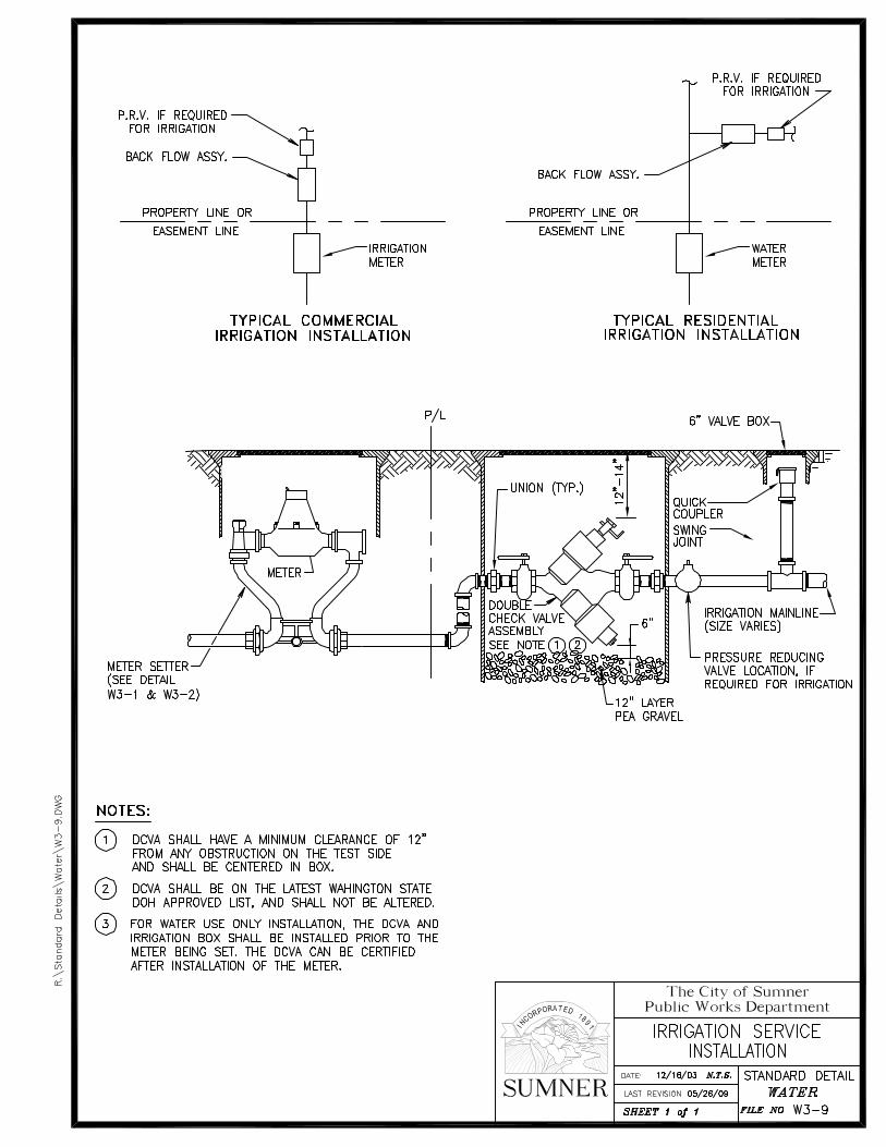


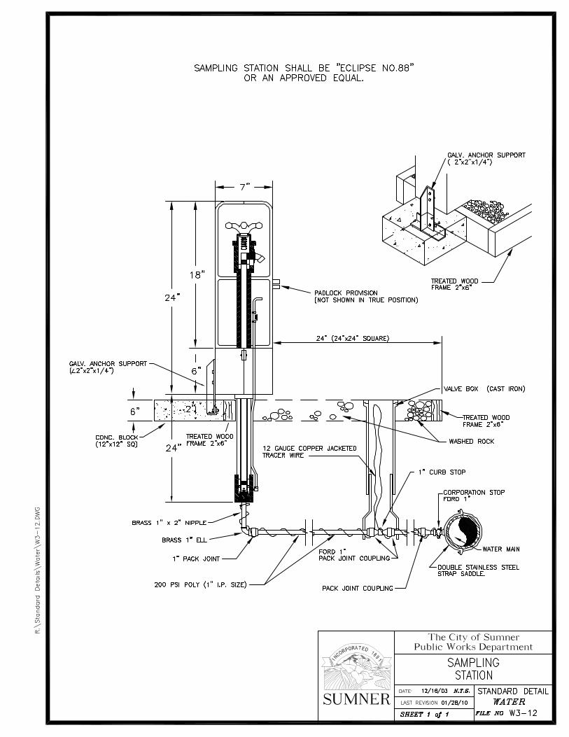


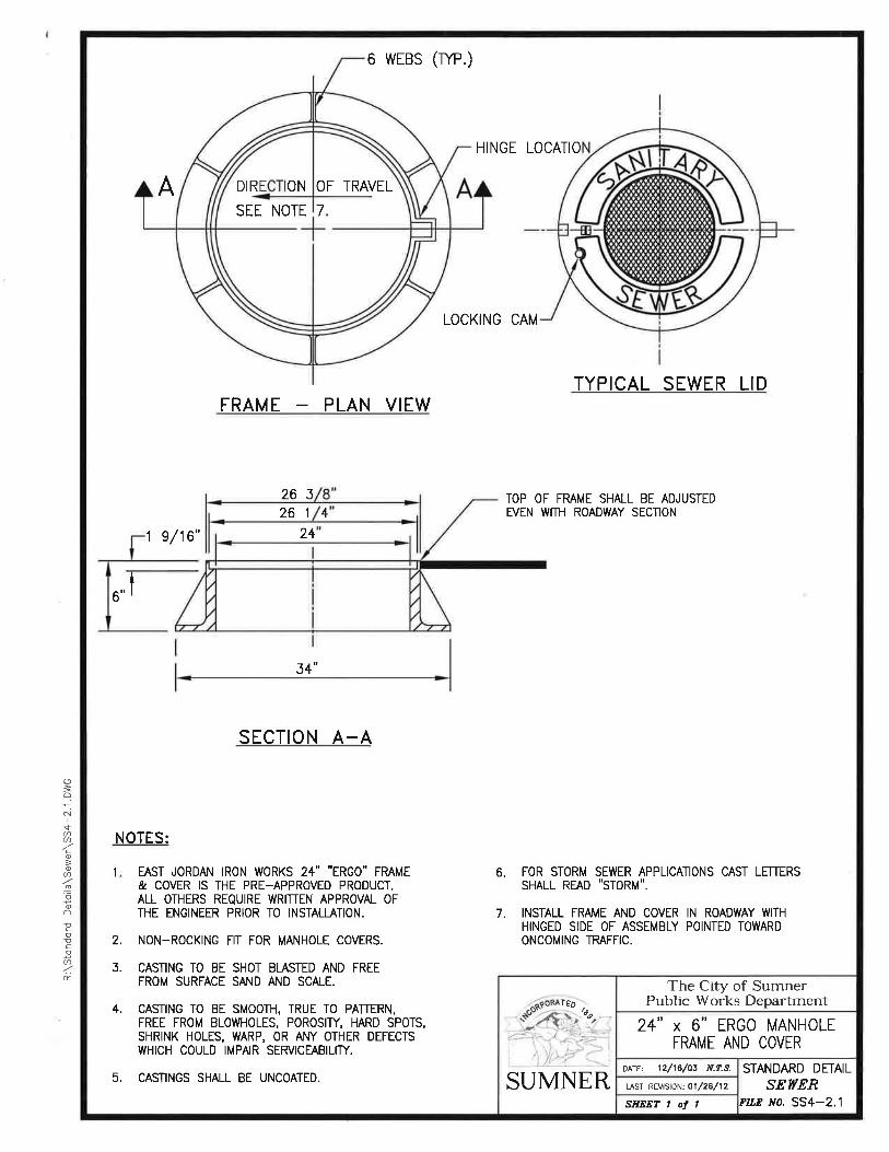


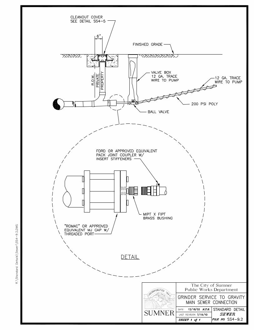


City of Sumner Public Works Department SSTTOORRMM
TABLE OF CONTENTS
SD5-1 CATCH BASIN TYPE II
SD5-2 CATCH BASIN TYPE I
SD5-3.1 FLOW CONTROL STRUCTURE
SD5-3.2 FLOW CONTROL STRUCTURE NOTES
SD5-4 CATCH BASIN FRAME AND GRATE
SD5-5 DAYLIGHT CULVERT OPEN DITCH
SD5-6 DAYLIGHT CULVERT DETENTION CHANNEL
SD5-7 DETENTION POND EMERGENCY OVERFLOW
SD5-8 TRASH RACK
SD5-9 SILTATION FENCE
SD5-10 CATCH BASIN TYPE II 48”-96”
SD5-11 INTENTIONALLY LEFT BLANK
SD5-12 INTENTIONALLY LEFT BLANK
SD5-13 BIOFILTRATION SWALE UNDERDRAIN


City of Sumner Public Works Department SSTTRREEEETT
TABLE OF CONTENTS R6-1.1 ROADWAY CROSS SECTION
R6-1.2 ROADWAY CROSS SECTION (NOTES)
R6-2.1 ALLEY CROSS SECTION
R6-2.2 ALLEY CROSS SECTION (NOTES)
R6-3 MONUMENT IN ASPHALT AREA
R6-4 PRECAST MONUMENT FOR OFF-ROAD USE
R6-5 SIDEWALK WITHOUT PLANTER STRIP
R6-6 SIDEWALK WITH PLANTER STRIP
R6-7 CURB AND GUTTER
R6-8 COMMERCIAL CONCRETE DRIVEWAY APPROACH
R6-9 RESIDENTIAL CONCRETE DRIVEWAY APPROACH
R6-10 PAVEMENT PATCHING
R6-11 INTENTIONALLY LEFT BLANK
R6-12 PRIVATE ACCESS ROADWAYS
R6-13.1 STREET TREES
R6-13.2 STREET TREES (CONT.)
R6-14 STREET TREES (SPECIES)
R6-15.1 SIGN MOUNTING
R6-15.2 SIGN MOUNTING
R6-16.1 STREET SIGNS FOR PRIVATE ROADS
R6-16.2 STREET NAME SINGS
R6-16.3 MAST ARM MOUNTED STREET NAME SIGNS
R6-17 THERMOPLASTIC CROSSWALK


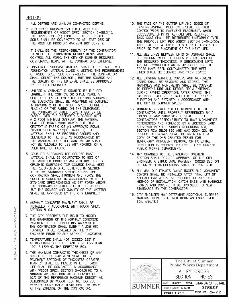


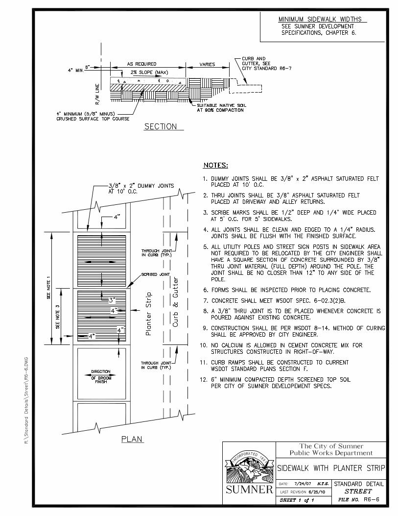
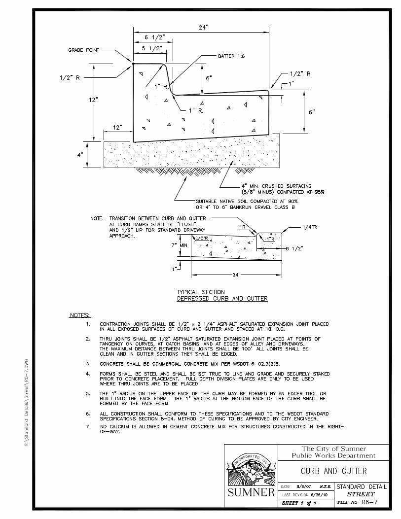


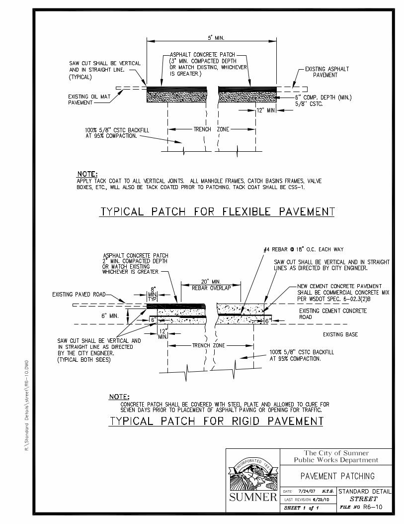


City of Sumner Public Works Department MMIISSCC..
TABLE OF CONTENTS M-1 STANDARD UTILITY LOCATIONS
M-2.1 WATER LINE AND SANITARY SEWER CONSTRUCTION
M-2.2 WATER LINE AND SANITARY SEWER CONSTRUCTION - NOTES
M-3.1 INTENTIONALLY LEFT BLANK
M-3.2 INTENTIONALLY LEFT BLANK
M-4 PIPE BEDDING
M-5.1 INTENTIONALLY LEFT BLANK
M-5.2 INTENTIONALLY LEFT BLANK
M-6 INTENTIONALLY LEFT BLANK
M-7.1 RESIDENTIAL SITE PLAN
M-7.2 RESIDENTIAL SITE PLAN – NOTES
M-8.1 TEMPORARY CONSTRUCTION ACCESS
M-8.2 TEMPORARY CONSTRUCTION ACCESS – NOTES
M-9 INTENTIONALLY LEFT BLANK
M-10 EMERGENCY VEHICLE ACCESS SIGNAGE
M-11 INTENTIONALLY LEFT BLANK
M-12 STREET LIGHT DESIGN GUIDLINE