Embed Size (px)
Citation preview
Southwest Research Institute® San Antonio, Texas
Developments in High
Efficiency Engine Technologies
DEER 2012
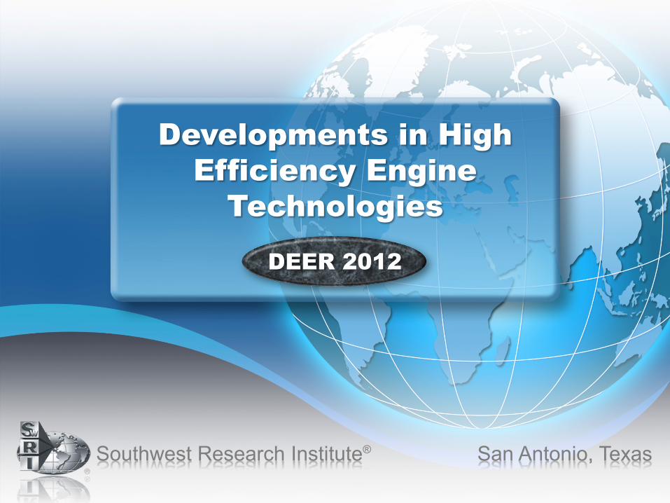
Drivers for High Efficiency
Demand for low
CO2 engines
Oil Price Volatility
Energy Security
Climate Change
Air Quality
Government Regulations
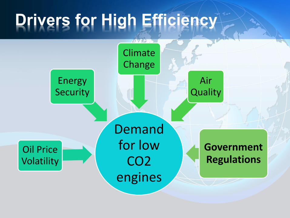
US 2025:107
EU 2020: 95
Japan 2020: 105China 2020: 117
90
110
130
150
170
190
210
230
250
270
2000 2005 2010 2015 2020 2025
Gra
ms
CO
2pe
r kilo
met
er, n
orm
aliz
ed to
NED
C
US-LDV
California-LDV
Canada-LDV
EU
Japan
China
S. Korea
Australia
Solid dots and lines: historical performanceSolid dots and dashed lines: enacted targets Solid dots and dotted lines: proposed targetsHollow dots and dotted lines: unannounced proposal
[1] China's target reflects gasoline fleet scenario. If including other fuel types, the target will be lower.[2] US and Canada light-duty vehicles include light-commercial vehicles.
CAFE – not just for light duty anymore
180
185
190
195
200
205
210
215
Engine AMY 2007
Engine BMY 2007
Engine CMY 2008
Engine DMY 2011
2014Standard
2017Standard
Fuel
cons
umpt
ion
[g/k
Wh]
0%
10%
20%
30%
40%
50%
60%
70%
80%
90%
0 5 10 15 20
Idea
l Ott
o Cy
cle
Effic
ienc
y
Geometric Compression Ratio
γ = 1.5
γ = 1.3
γ = 1.4
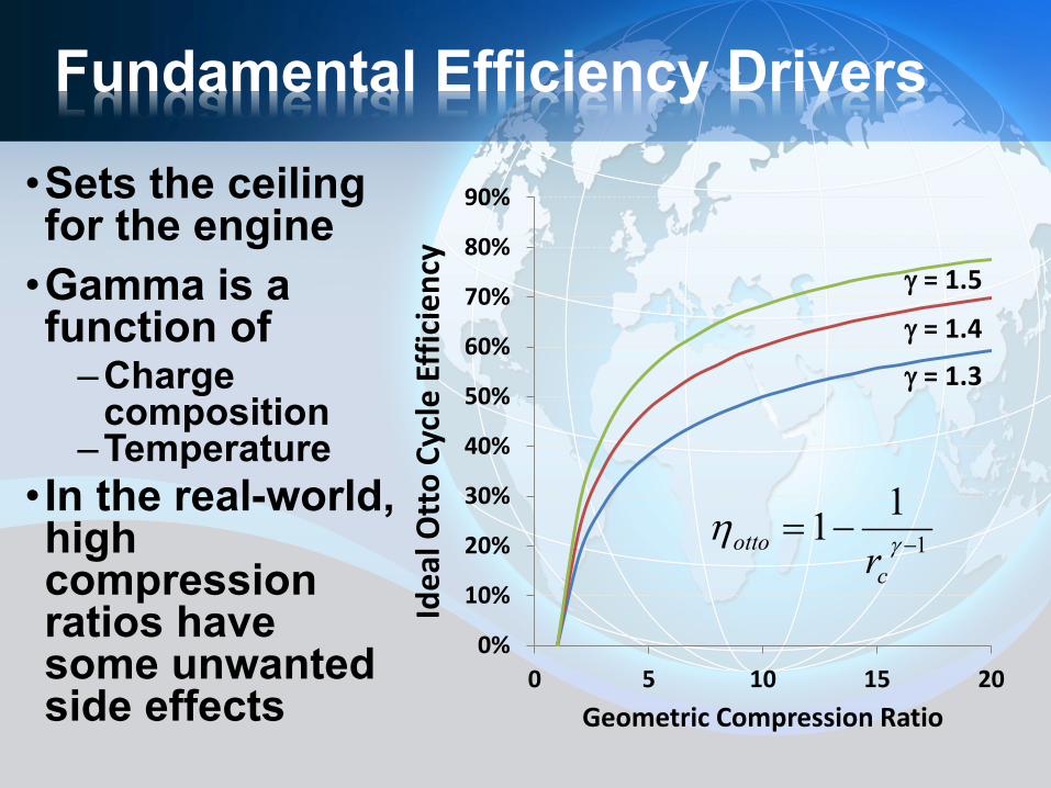
Fundamental Efficiency Drivers
•Sets the ceiling for the engine •Gamma is a function of
–Charge composition
–Temperature • In the real-world, high compression ratios have some unwanted side effects
111 −−= γη
cotto r
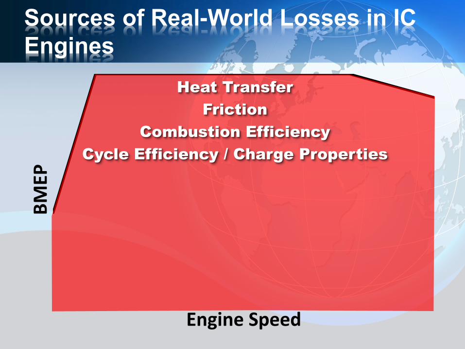
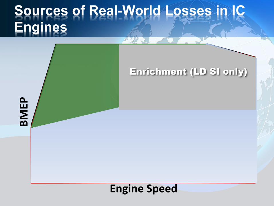
Sources of Real-World Losses in IC Engines
BMEP
Engine Speed
Heat Transfer Friction
Combustion Efficiency Cycle Efficiency / Charge Properties
BMEP
Engine Speed
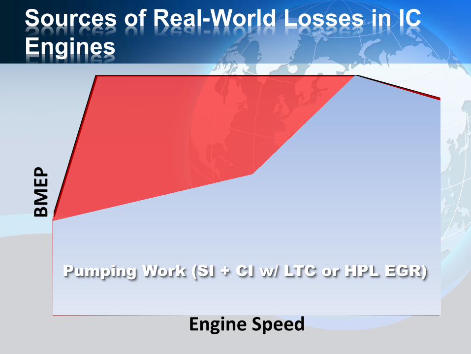
Sources of Real-World Losses in IC Engines
Pumping Work (SI + CI w/ LTC or HPL EGR)
BMEP
Engine Speed
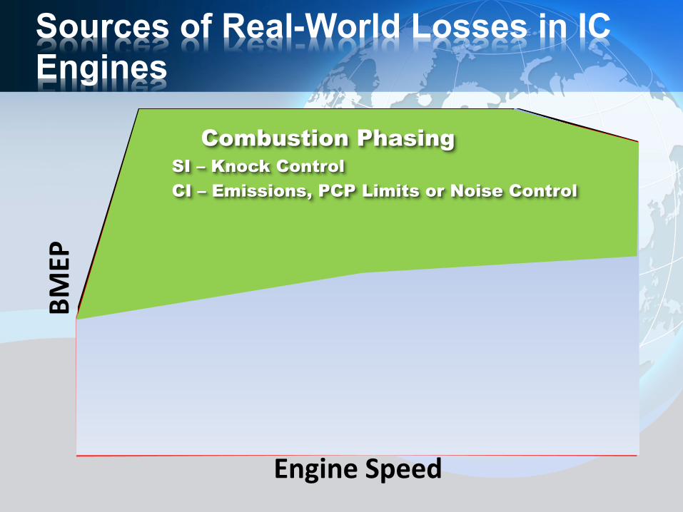
Sources of Real-World Losses in IC Engines
Combustion Phasing SI – Knock Control CI – Emissions, PCP Limits or Noise Control
BMEP
Engine Speed
Sources of Real-World Losses in IC Engines
Enrichment (LD SI only)
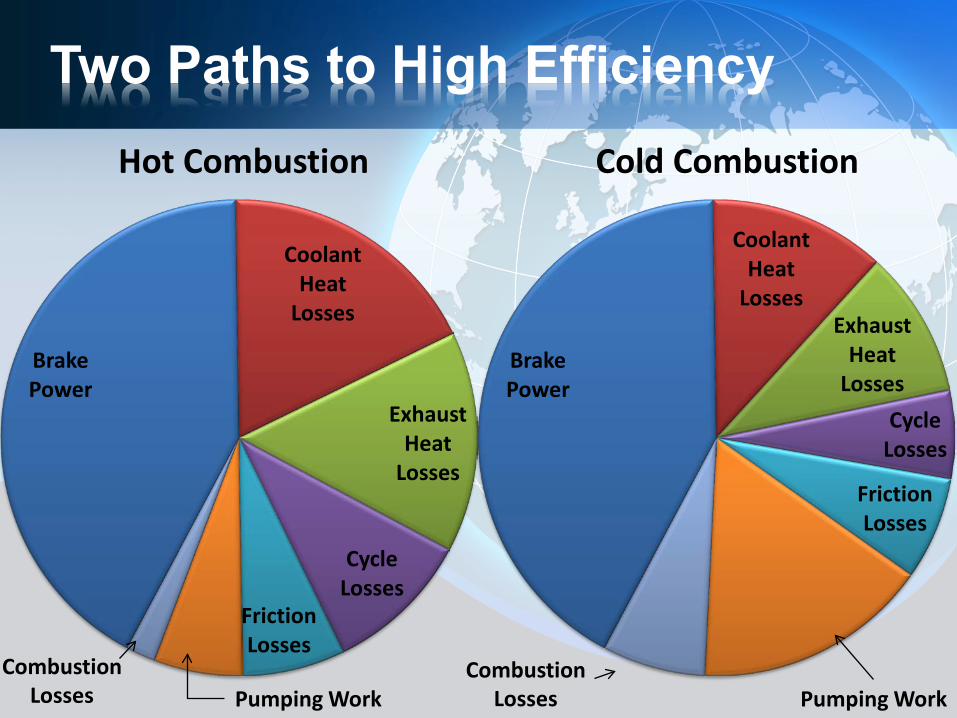
Two Paths to High Efficiency
Brake Power
Coolant Heat
Losses
Exhaust Heat
Losses
Cycle Losses
Friction Losses
Hot Combustion
Combustion Losses Pumping Work
Brake Power
Coolant Heat
Losses Exhaust
Heat Losses
Cycle Losses
Friction Losses
Cold Combustion
Pumping Work Combustion
Losses
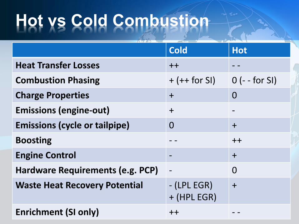
Hot vs Cold Combustion Cold Hot
Heat Transfer Losses ++ - - Combustion Phasing + (++ for SI) 0 (- - for SI) Charge Properties + 0 Emissions (engine-out) + - Emissions (cycle or tailpipe) 0 + Boosting - - ++ Engine Control - + Hardware Requirements (e.g. PCP) - 0 Waste Heat Recovery Potential - (LPL EGR)
+ (HPL EGR) +
Enrichment (SI only) ++ - -
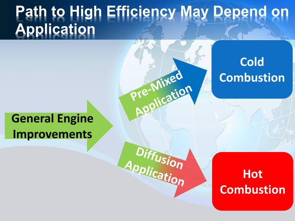
Path to High Efficiency May Depend on Application
General Engine Improvements
Cold Combustion
Hot Combustion
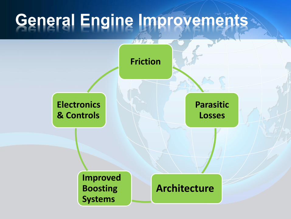
General Engine Improvements
Friction
Parasitic Losses
Architecture Improved Boosting Systems
Electronics & Controls
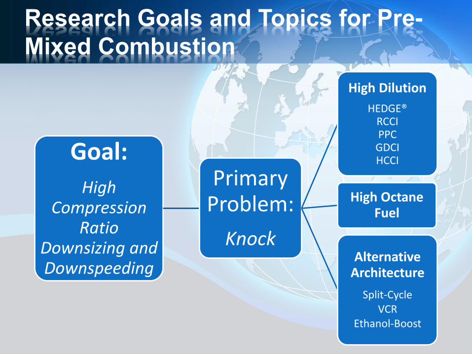
Research Goals and Topics for Pre-Mixed Combustion
Goal: High
Compression Ratio
Downsizing and Downspeeding
Primary Problem:
Knock
High Dilution HEDGE®
RCCI PPC
GDCI HCCI
High Octane Fuel
Alternative Architecture
Split-Cycle VCR
Ethanol-Boost
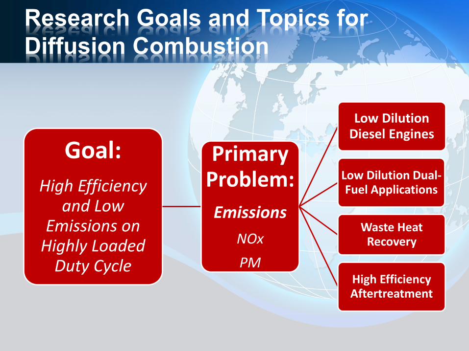
Research Goals and Topics for Diffusion Combustion
Goal: High Efficiency
and Low Emissions on
Highly Loaded Duty Cycle
Primary Problem: Emissions
NOx PM
Low Dilution Diesel Engines
Low Dilution Dual-Fuel Applications
Waste Heat Recovery
High Efficiency Aftertreatment
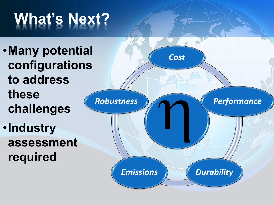
What’s Next?
•Many potential configurations to address these challenges •Industry assessment required
Cost
Performance
Durability Emissions
Robustness η
Southwest Research Institute® San Antonio, Texas
Introduction to SwRI’s Dedicated EGR
Concept DEER 2012
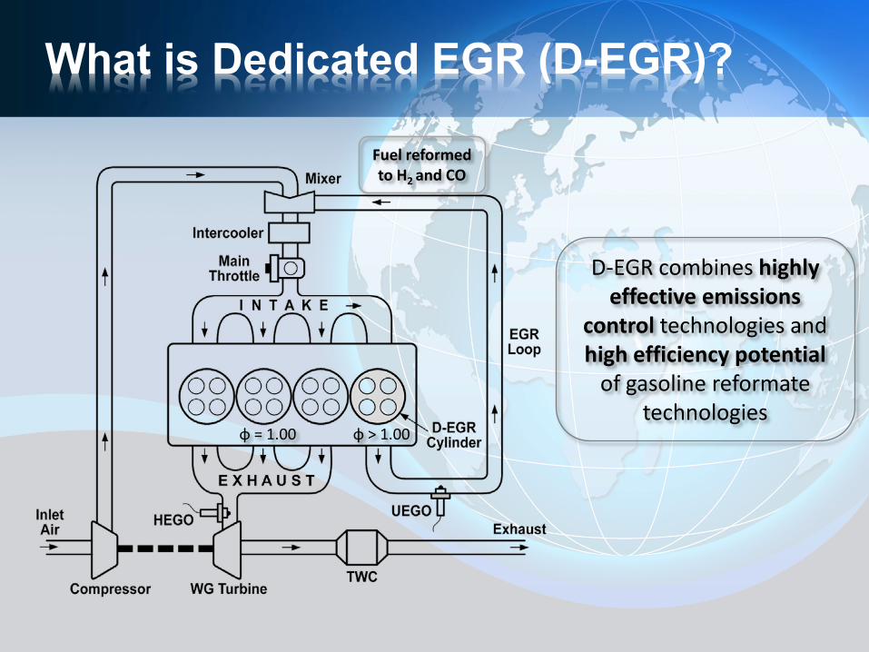
What is Dedicated EGR (D-EGR)?
D-EGR combines highly effective emissions
control technologies and high efficiency potential
of gasoline reformate technologies
Fuel reformed to H2 and CO
ɸ = 1.00 ɸ > 1.00
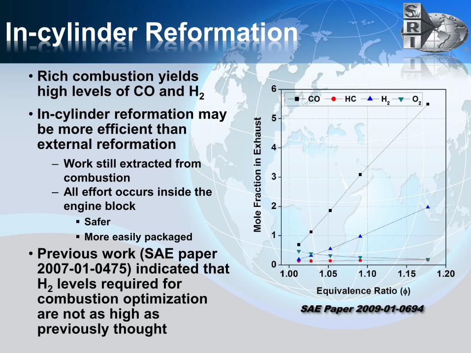
In-cylinder Reformation • Rich combustion yields
high levels of CO and H2
• In-cylinder reformation may be more efficient than external reformation
– Work still extracted from combustion
– All effort occurs inside the engine block Safer More easily packaged
• Previous work (SAE paper 2007-01-0475) indicated that H2 levels required for combustion optimization are not as high as previously thought
SAE Paper 2009-01-0694
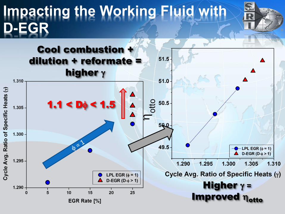
Impacting the Working Fluid with D-EGR
Cool combustion + dilution + reformate =
higher γ
Higher γ = Improved ηotto
1.1 < Dφ < 1.5
1.00 1.05 1.10 1.15 1.20 1.250
2
4
6
8
10
CoV
IMEP
[%]
Cylinder #1 φ
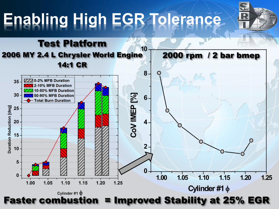
Enabling High EGR Tolerance
2000 rpm / 2 bar bmep Test Platform
2006 MY 2.4 L Chrysler World Engine 14:1 CR
Faster combustion = Improved Stability at 25% EGR
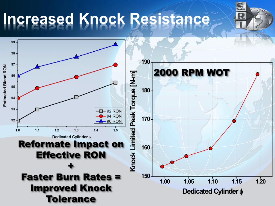
Increased Knock Resistance
Reformate Impact on Effective RON
+ Faster Burn Rates =
Improved Knock Tolerance
1.00 1.05 1.10 1.15 1.20150
160
170
180
190
Knoc
k Li
mite
d Pe
ak T
orqu
e [N
-m]
Dedicated Cylinder φ
2000 RPM WOT
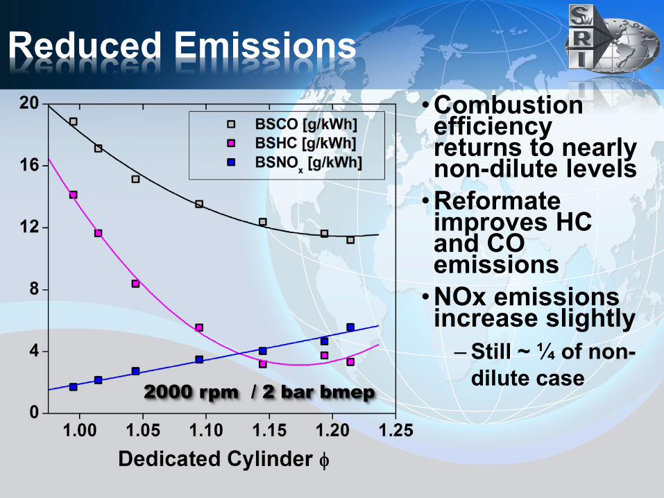
Reduced Emissions •Combustion efficiency returns to nearly non-dilute levels •Reformate improves HC and CO emissions •NOx emissions increase slightly
– Still ~ ¼ of non-dilute case 2000 rpm / 2 bar bmep
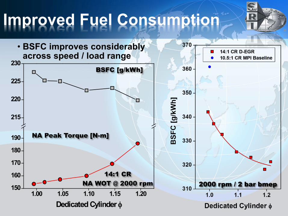
Improved Fuel Consumption • BSFC improves considerably
across speed / load range
2000 rpm / 2 bar bmep 1.00 1.05 1.10 1.15 1.20
150
160
170
180
190
215
220
225
230
Dedicated Cylinder φ
BSFC [g/kWh]
NA Peak Torque [N-m]
14:1 CR NA WOT @ 2000 rpm
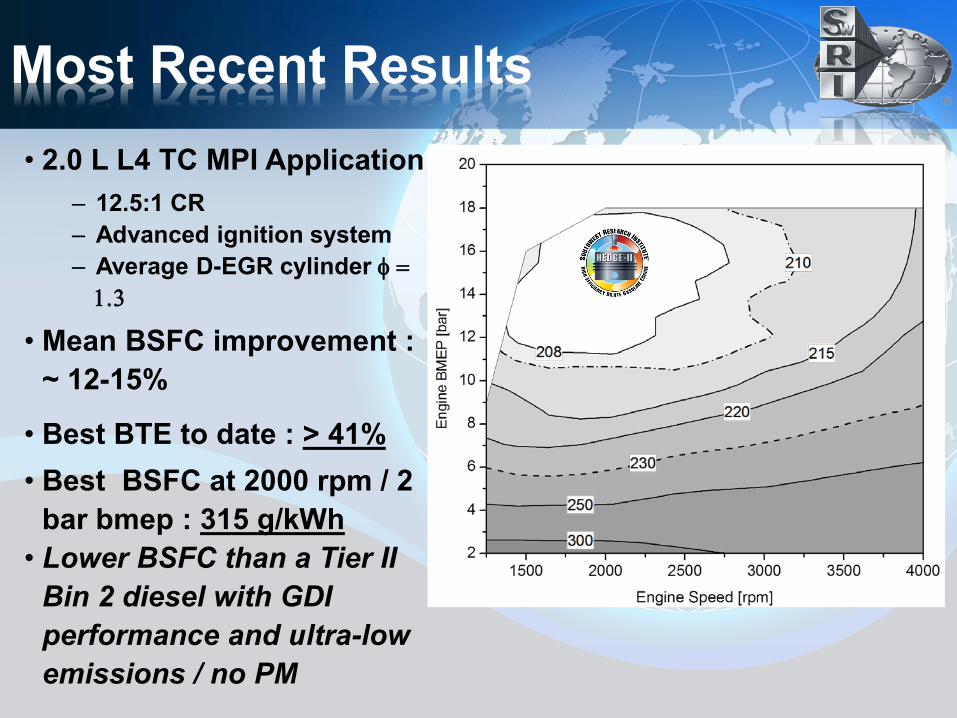
Most Recent Results • 2.0 L L4 TC MPI Application
– 12.5:1 CR – Advanced ignition system – Average D-EGR cylinder φ =
1.3
• Mean BSFC improvement : ~ 12-15%
• Best BTE to date : > 41% • Best BSFC at 2000 rpm / 2
bar bmep : 315 g/kWh • Lower BSFC than a Tier II
Bin 2 diesel with GDI performance and ultra-low emissions / no PM
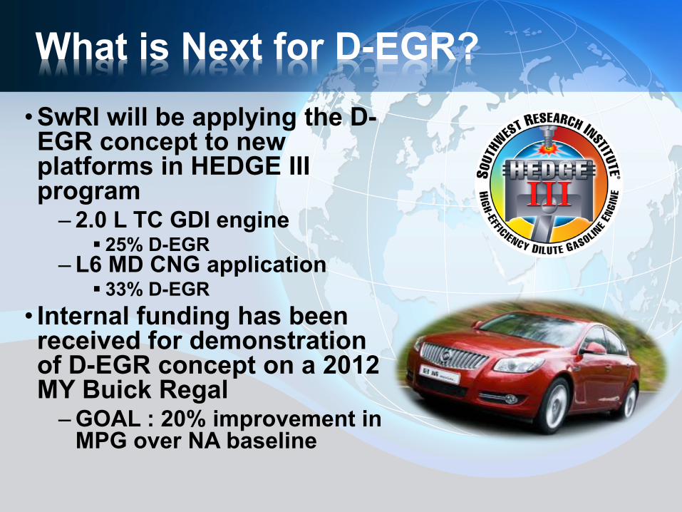
What is Next for D-EGR? •SwRI will be applying the D-EGR concept to new platforms in HEDGE III program
– 2.0 L TC GDI engine 25% D-EGR
– L6 MD CNG application 33% D-EGR
• Internal funding has been received for demonstration of D-EGR concept on a 2012 MY Buick Regal
– GOAL : 20% improvement in MPG over NA baseline
Thank You
Southwest Research Institute®