Embed Size (px)
Citation preview

1
DEVELOPMENTS OF PC BASED CONTROLLER FOR BUCK CONVERTER DRIVEN DC MOTOR
NURSYAHIDA ASHIKIN BINTI NOR IZLANIN
This thesis is submitted as partial fulfillment of the requirements for the award of the
degree of Bachelor of Electrical Engineering (Power Systems)
Faculty of Electrical & Electronics Engineering
University Malaysia Pahang
NOVEMBER, 2010

i
SUPERVISOR’S DECLARATION
I hereby declare that I have read this project report and in my opinion this project report is
sufficient in terms of scope and quality for the award of Bachelor in Electrical Engineering
(Power System)
Signature :
Name of Supervisor : MR RAJA MOHD AUFIKA RAJA ISMAIL
Date :

ii
STUDENT’S DECLARATION
I hereby declare that the work in this report is my own except for quotations and summaries
which have been duly acknowledged. The report has not been accepted for any degree and is not
concurrently submitted for award of other degree.
Signature :
Name : NURSYAHIDA ASHIKIN BINTI NOR IZLANIN
ID Number : EC07016
Date : 09 NOVEMBER 2010

iv
ACKNOWLEDGEMENT
I would like to express my gratitude and appreciation to all those who gave me the
possibility to complete this report. Special thanks is due to my supervisor Mr. Raja Mohd
Taufika Raja Ismail who’s help, stimulating suggestions and encouragement helped me in all
time to successful this project and in writing this report.
Many thanks go to the all lecturer and supervisors who have given their full effort in
guiding the team in achieving the goal as well as their encouragement to maintain our progress in
track. My profound thanks go to all classmates, especially to my friends for spending their time
in helping and giving support. Not forgetting for my parent and family who are fully support me
in every condition. Thanks All.
v
ABSTRACT
Switched Mode Power Supplies (SMPS) is the technique proposed in this investigation
to control the speed of DC motor. In the design of these power supplies, the semiconductor
devices are either switched on or off. It is highly efficient because of the low voltage drop across
the semiconductor device when it is on and cause the power consumption is low. The power
supply is consists of rectifier and Buck converter. The implementation the PWM Chopper with a
MOSFET also needed because nowadays, the chopper switch is obviously a fast power
MOSFET with very short switching times and low resistance that reduce the conductive losses
but produce extremely high voltage- and current-rates. As the result, PWM signal is used to
control the speed of the motor and the output voltage of the buck converter with the adding of PC
interface in order to make it easy and friendly user system.

vi
ABSTRAK
Switched Mode Power Supply (SMPS) adalah teknik yang dicadangkan dalam
penyiasatan untuk menyiapkan projek ini iaitu untuk mengawal kelajuan motor arus terus (DC).
Dalam mereka pembekal kuasa ini, semikonduktor samada suisnya buka atau tutup, ia
mempunyai kecekapan yang tinggi kerana kadar kejatuhan voltage adalah rendah apabila melalui
semikonduktor dan mengakibatkan penggunaan kuasa juga adalah rendah. Pembekal kuasa ini
adalah terdiri daripada rectifier dan buck converter. Penghasilan PWM Chopper dengan
MOSFET juga sangat diperlukan sekarang kerana suis chopper adalah terbukti sebagai MOSFET
yang mempunyai masa suis yg sangat rendah dan rintangan yang rendah yang dapat
mengurangkan kehilangan konduktor tetapi menghasilkan kadar voltan dan elektrik yang tinggi.
Kesimpulannya, Pulse Width Modulation (PWM) digunakan untuk mengawal kelajuan motor
dan kadar keluran voltan daripada buck converter dengan penambahan sistem interface komputer
dalam menghasilkan sistem yang mudah dan selesa bagi pengguna.

vii
TABLE OF CONTENTS
CHAPTER TITLE PAGE
SUPERVISOR’S DECLARATION i STUDENT’S DECLARATION ii DEDICATION iii ACKNOWLEDGEMENT iv ABSTRACT v ABSTRAK vi TABLE OF CONTENT vii LIST OF TABLE x LIST OF FIGURE xi
1 INTRODUCTION
1.1 Introduction 1
1.2 Background 1
1.3 Objective 2
1.4 Scope of the Project 2
1.5 Problem Statement 2
1.6 Project Background 3
1.6.1 Overview of chopper drive and buck-converter 3
1.6.2 Methodology of the Project 3
1.7 Thesis Outline 4
2 LITERATURE REVIEW
2.1 Introduction 5
2.2 DC Motor 6
2.3 Chopper Drive 7

viii
2.4 Switched Mode Power Supply (SMPS) 9
2.4.1 DC-DC Converter 11
2.4.2 Buck Converter 11
2.5 Pulse Width Modulation (PWM) 16
3 METHODOLOGY
3.1 Introduction 18
3.2 PWM Chopper Drive 18
3.3 PWM Signal Generation 20
3.4 Speed Feedback 20
3.5 Control Signal Generation and Implementation of PIC
Controller In Software. 21
3.6 Main Component 21
3.6.1 DC Motor 21
3.6.2 Buck Converter 22
3.6.3 RS232 DB9 Connector 23
4 HARDWARE DESIGN
4.1 Introduction 25
4.2 Designing Input Voltage of The Buck Converter 25
4.3 Designing The Buck Converter 26
4.4 Pulse Width Modulation (PWM) Generation 27
4.5 Development of the Project 28
4.7.1 Simulation Stage 28
4.7.1.1 Rectification Design 28
4.7.1 2 Buck Converter Simulation 28
4.7.2 Hardware Stage 29
4.7.2.1 Rectification Hardware 29
4.7.2.2 Buck Converter Hardware 30
4.7.3 PWM Generator Hardware 30

ix
4.7.4 PC Interface 31
5 RESULT AND CONCLUSION
5.1 Introduction 33
5.2 Simulation Result 33
5.2.1 Voltage Output From Buck Converter 33
5.2.2 PWM Output From PIC 16F877A 34
5.3 Hardware Result 34
5.3.1 Buck Converter Construction 35
5.3.2 Buck Converter Output Result 35
5.4 Rectification Result 38
5.5 PWM Output 38
5.5.1 PWM Output From Motor 39
5.5.2 PWM Output From Serial Port 42
5.6 Analysis 45
5.7 Discussion 45
5.8 Summary 45
6 CONCLUSION AND RECOMMENDATION
6.1 Introduction 46
6.2 Conclusion 46
6.3 Future Recommendation 47
6.4 Costing And Commercialization 47
REFERENCES
APPENDICES

x
LIST OF TABLES
Table No. Title Page
2.1 DC Motor Characteristics and Applications 6
5.1 Result for DC Motor Speed 36
6.1 Costing for the Project 48

xi
LIST OF FIGURES
Figure No. Title Page
1.1 The block diagram of the project 4
2.1 Step-Down Chopper Circuit 8
2.2 Step-down chopper switching waveform 8
2.3 Basic SMPS block diagram 10
2.4 General Block Diagram for DC to DC converter 11
2.5 Buck Regulator Step Down 12
2.6 Circuit When Switch is On 14
2.7 Circuit When Switch is Off 15
2.8 The Resultant of Wave When Switch is On and Off 15
2.9 A simple PWM circuit 16
2.10 Duty Cycle of 50% Pulse Width from 5V supply 17
2.11 Duty Cycle of 70% Pulse Width from 5V supply 17
3.1 Chooper Drive Block Diagram 18
3.2 The Resultant Voltage Wave 19
3.3 The Basic Chopper Circuit 19
3.4 Process to generate PWM Wave 20
3.5 The Sensor For Giving Feedback 20
3.6 Process for PIC controller 21

xii
3.7 The Resultant for the Chopper Switch 22
3.8 RS232 DB9 Pin out 24
4.1 Simulation Buck Converter Circuit 26
4.2 Duty Cycle from PIC using PROTUSE software 27
4.3 Hardware of Rectification 29
4.4 Buck Converter Hardware 30
4.5 Hardware for PWM generator 31
4.6 Connection of DB09 and hardware 32
5.1 Result of MOSFET From Simulation 34
5.2 Buck Converter connected to the DC motor 35
5.3 Graph of Speed in RPM versus Duty Ratio 37
5.4 Graph of Output voltage versus Duty Cycle 37
5.5 Rectification Result from Hardware 38
5.6 PWM for 0% duty cycle 39
5.7 PWM for 12.5% duty cycle 39
5.8 PWM for 25% duty cycle 39
5.9 PWM for 37.5% duty cycle 40
5.10 PWM for 50% duty cycle 40
5.11 PWM for 62.5% duty cycle 40
5.12 PWM for 75% duty cycle 41
5.13 PWM for 87.5% duty cycle 41
5.14 PWM for 100% duty cycle 41
5.15 PWM for 0% duty cycle 42
xiii
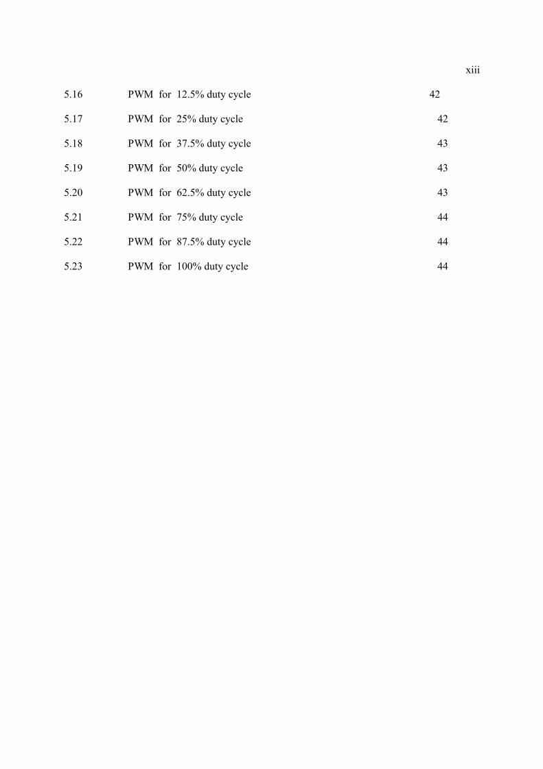
5.16 PWM for 12.5% duty cycle 42
5.17 PWM for 25% duty cycle 42
5.18 PWM for 37.5% duty cycle 43
5.19 PWM for 50% duty cycle 43
5.20 PWM for 62.5% duty cycle 43
5.21 PWM for 75% duty cycle 44
5.22 PWM for 87.5% duty cycle 44
5.23 PWM for 100% duty cycle 44

1
CHAPTER 1
INTRODUCTION
1.1 Introduction
This chapter will explain the objectives of the project, scope of the project,
problem statement and the project background. The review of the DC motor, chopper
drive, buck converter and pulse width modulation (PWM) control also will be
explained in this chapter. At the end of chapter 1 the thesis outline is briefly
described.
1.2 Background
The DC motor is an attractive piece of equipment in many industrial
applications requiring variable speed and load characteristics due to its ease of
controllability. The “Chopper drive” based speed controlling method is superior in
comparison to “Thyristor Controlled Bridge Rectifier” method as far as DC motor
speed controlling is concerned. PC based software controlling is adopted to retain
simplicity & ease of implementation.
By using PC and a circuit driver in controlling speed of a DC motor, the speed
of a DC motor can easily handle and measure by the user. From this project also will
shows the required signal generation to drive the chopper.

2
A Closed-loop designing a complete automatic speed control system for a DC
motor and will brings the motor to the speed set by the user irrespective of the load.
1.3 Objective Of The Project
The project has these following objectives:
To evolve of a PWM Signal Generator for chopper drive
To design and apply chopper circuit in controlling DC motor
To develop software implementation for interface
1.4 Scope Of The Project
This project is developed by using input from PWM signal generation to get
PWM output. The implementation the PWM Chopper with a MOSFET also needed
because nowadays, the chopper switch is obviously a fast power MOSFET with very
short switching times and low resistance that reduce the conductive losses but
produce extremely high voltage- and current-rates [2]. Program code also will be
created to drive the hardware circuitry by using MATLAB and the implementation of
PIC controller will be used for this project.
1.5 Problem Statement
Due to its ease of controllability, the DC motor is an attractive piece in
requiring variable speed and load characteristics. Hence, the ‘Chopper drive” based
speed controlling method detected as superior in comparison to “Thyristor
Controlled Bridge Rectifier” method. It is also adopted to retain simplicity and ease
of implementation. PC interfacing also will be giving the easier way to the user on
how to control the motor speed.
3
1.6 Project Background
The overview of chopper drive and buck-converter will take part for this
section besides the methodology in developing this project. In addition, the
methodology will be best described in the block diagram as in Figure 1.
1.6.1 Overview Of Chopper Drive And Buck-Converter
The chopper is used to control the armature voltage of a DC motor [1].
Chopper drive circuits are also referred to as constant current drives because they
generate a somewhat constant current in each winding rather than applying a
constant voltage. A Buck converter consists of the power stage and feedback control
circuit. The power stage includes power switch and output filter. It converts a higher
input voltage to a lower output voltage. The feedback control circuit regulates the
output voltage by modulating the power switch duty cycle. The three basic this dc-
dc converters use a pair of switches, usually one controlled (MOSFET) and one
uncontrolled (diode) in order to achieve unidirectional power flow from input to
output.
1.6.2 Methodology of the Project
In the research of this project, motor will receives the input from the DC
source. Signal also will be send to the motor through the chopper after PWM
generator gives the output to the chopper that is result from the feedback speed.
Feedback speed that comes from the sensor attached to motor will be the input to the
PWM generator and PIC controller. This project will be applying the closed-loop
system. A closed-loop designing a complete automatic speed control system for a DC
motor and will brings the motor to the speed set by the user irrespective of the load.

4
Figure 1: The block diagram of the project
1.7 Thesis Outline
This thesis is divided into 6 chapters which the content of each chapter is summarized as below.
Chapter 1 will be discussed about the overview of the concept of the project,
objective of the project and scope of the project.
Chapter 2 will be described briefly the hardware components used in this
project, including their description of operation and article review of the project.
Chapter 3 will be focused on the methodology of this research project which
includes the generation of power supply, generation of PWM waveform for the
motor and full circuit diagram of the project.
Chapter 4 will elaborated in detailed about the designing step of buck
converter and chopper drive, PMW generation and the PIC controller design.
Chapter 5 will focused on the result obtained from the simulation design
using MATLAB and PROTUSE, the result obtained from hardware design and PC
interface.
Chapter 6 will described the conclusion from the result and observation, the
future recommendation and costing besides the commercialization of the project.

5
CHAPTER 2
LITERATURE REVIEW
2.1 Introduction
In this chapter will explain in detail the operation of buck converter and
chopper drive. Besides that, DC motor and pulse width modulation also will be part
of the explanation in this chapter. In addition, all the circuit diagram and element that
are related in order to develop this project also will be reviewed in detail.
2.2 Dc Motor
DC motor is a mechanical workhorse. Many large pieces equipment depend
on a DC motor for power to move. A DC motor rotates as a result of two magnetic
fields interacting with one another. There are three categories for the DC motor like
series DC motor, shunt DC motor and compound DC motor.
The speed control is concerned not only with starting the motor but also with
maintaining or controlling the motor speed while it is running. There are a number of
conditions to be considered for speed control for example constant speed, varying
speed, adjustable speed and multispeed[3].

6
Table 2.1 : DC Motor Characteristics and Applications [7]
Speed Regulation
Speed Control Starting Torque Pull-out Torque Application
Series DC MotorVaries inversely as the load. Races on light loads and full voltages in
Zero to maximum, depending on control and load.
High. Varies as square of voltage. Limited by the communication, heating, and line capacity.
High. Limited by communication, heating, and line capacity.
Where high torque is required and speed can be regulated.
Shunt DC MotorDrops 3% to 5% from no load to full load.
Any desired range, depending on motor design and type of system
Good with constant field, varies directly as voltage applied to the armature
High. Limited by communication, heating, and line capacity
Where constant speed is needed and starting conditions are not severe
Compound DC MotorDrops 3% to 2% from no load to full load depending on the amount of compounding
Any desired range, depending on motor design and type of control
Higher than for shunt, depending on the amount of compounding
High. Limitedby communication, heating, and line capacity
Where high starting torque combine with fairly constant speed is required.
For this project, stepper motor is chosen that its speed will be controlled by
the computer. The stepper motor is designed to move in finite increments (steps) in
either direction and to keep track of how many steps have been taken at any point in
time. The stepper motor can be used with mechanical linkages to provide precise
positioning. [2]
2.3 Chopper Drive
DC motor drives are used for many speed and position control systems where
their excellent performance, ease of control and high efficiency are desirable
characteristics. DC motor speed control can be achieved using switch mode DC to
DC chopper circuits.
7
Chopper Driver is chosen for this project due to the advantages against the
Thyristor. These are the following advantages over Thyristor Bridge Rectifiers
method:
High energy efficiency
Flexibility in control
Quick Response
Light weight & compact control unit
Less ripple in the armature current
Small discontinuous conduction region in the Speed-Torque plane
Small discontinuous conduction region improves the speed regulation and
transient response of the drive
Less amount of machine losses due to less ripple in the armature current
Ability to control down to very low speeds [4]
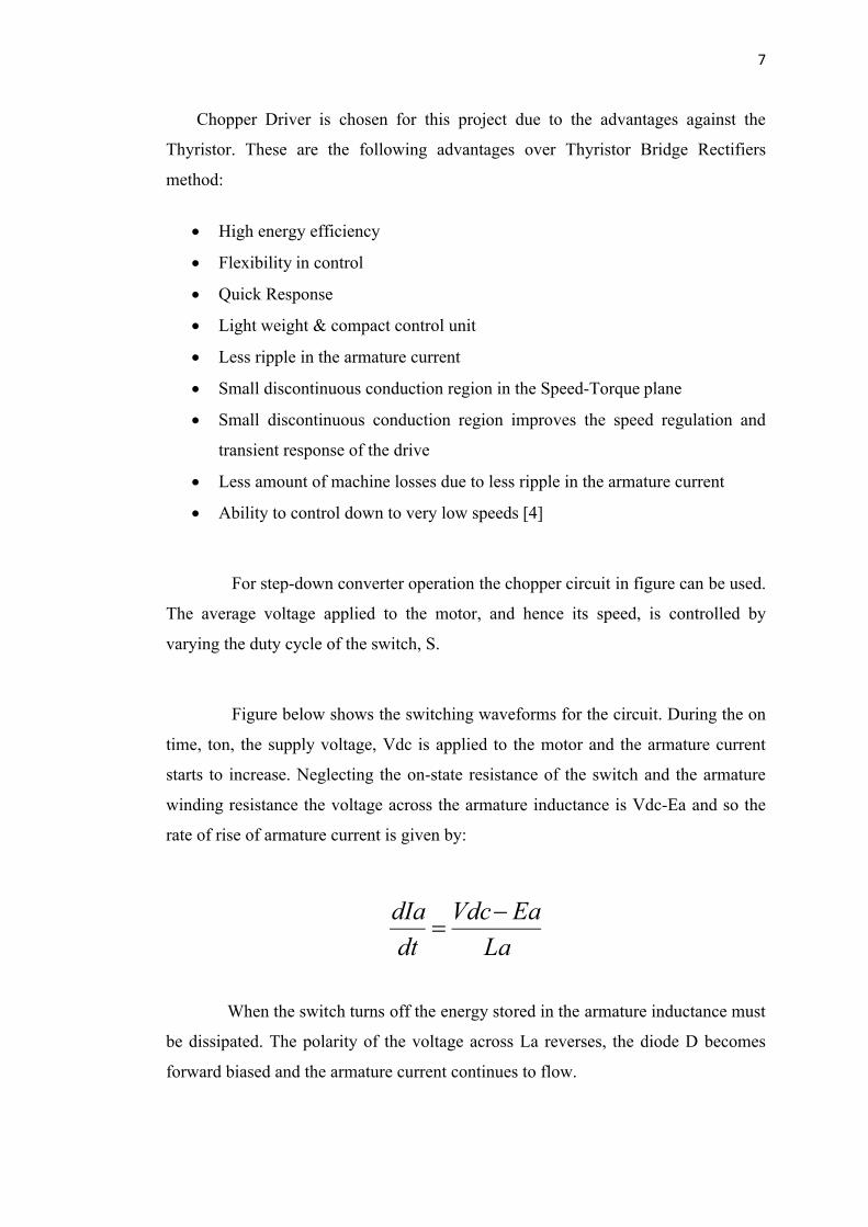
For step-down converter operation the chopper circuit in figure can be used.
The average voltage applied to the motor, and hence its speed, is controlled by
varying the duty cycle of the switch, S.
Figure below shows the switching waveforms for the circuit. During the on
time, ton, the supply voltage, Vdc is applied to the motor and the armature current
starts to increase. Neglecting the on-state resistance of the switch and the armature
winding resistance the voltage across the armature inductance is Vdc-Ea and so the
rate of rise of armature current is given by:
La
EaVdc
dt
dIa
When the switch turns off the energy stored in the armature inductance must
be dissipated. The polarity of the voltage across La reverses, the diode D becomes
forward biased and the armature current continues to flow.
8
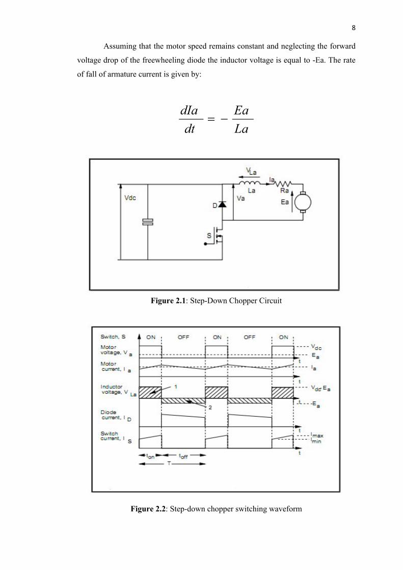
Assuming that the motor speed remains constant and neglecting the forward
voltage drop of the freewheeling diode the inductor voltage is equal to -Ea. The rate
of fall of armature current is given by:
La
Ea
dt
dIa
Figure 2.1: Step-Down Chopper Circuit
Figure 2.2: Step-down chopper switching waveform

9
If this switching sequence is repeated at some frequency, then the motor
voltage can be controlled by altering the relative duration of the on period and off
period. Variation of the duty cycle of the switch (ton/T) to control the motor voltage
is referred to as Pulse Width Modulation (PWM) control. As the average voltage
across the inductor over a period must be zero then:
T
t L
t
L
T
Lon
on
dtVdtVdtV 0...00
The integral of inductor voltage for the interval ton corresponds to the
shaded area1 in figure, whilst the integral of inductor voltage for the toff interval
corresponds to the shaded area 2 in the Figure 2.2.
These two areas must be equal and so from equations and figure the transfer
function of the controller is given by:
dcon
a VT
tV .
2.4 Switched Mode Power Supply (SMPS)
For many years the world of power supply design has seen a gradual
movement away from the use of linear power supplies to the more practical Switched
Mode Power Supply (SMPS). The linear power supply contains a mains transformer
and a dissipative series regulator. This means the supply has extremely large and
heavy 50/60 Hz transformers, and also very poor power conversion efficiencies, both
serious drawbacks. Typical efficiencies of 30% are standard for a linear. This
compares with efficiencies of between 70 and 80%, currently available using SMPS
designs.

10
Furthermore, by employing high switching frequencies, the sizes of the
power transformer and associated filtering components in the SMPS are dramatically
reduced in comparison to the linear. This means an SMPS design can produce very
compact and lightweight supplies. This is now an essential requirement for the
majority of electronic systems. The supply must slot into an ever shrinking space left
for it by electronic system designers.
Figure 2.3: Basic SMPS block diagram
An SMPS can be a fairly complicated circuit, as can be seen from the block
diagram shown in figure above. (This configuration assumes a 50/60Hz mains input
supply is used.) The ac supply is first rectified, and then filtered by the input
reservoir capacitor to produce a rough DC input supply. This level can fluctuate
widely due to variations in the mains. In addition the capacitance on the input has to
be fairly large to hold up the supply in case of a severe droop in the mains. The
SMPS can also be configured to operate from many suitable dc input, in this case the
supply is called a DC to DC converter. In a switching converter circuit, the transistor
operates as an electronic switch by being completely on or completely off and this
circuit is also known as a DC chopper [6].

11
2.4.1 DC – DC Converter
DC to DC converter is an electronic circuit which converts a source of direct
current (DC) from one voltage level to another.
There are few converters that are listed in this DC to DC converter such as:
Buck Converter
Boost Converter
Buck Boost Converter
Cuk converter
Full bridge converter
Figure 2.4: General Block Diagram for DC to DC converter
Switching power supplies offer higher efficiency than traditional linear
power supplies. They can step-up, step-down, and invert. Some designs can isolate
output voltage from the input. The switching regulator used in DC-DC converter and
this may be a simple way of converting a DC supply voltage to a lower Dc voltage
and regulating the output[6].
2.4.2 Buck Converter
A buck converter is a step-down DC to DC converter. Its design is similar to
the step-up boost converter. It is a switched-mode power supply that uses two
switches (a transistor and a diode), an inductor and a capacitor similarly like the
Boost Converter. The diode provides a path for the inductor current when the switch
is opened and is reverse biased when the switch is closed.