Embed Size (px)
Citation preview
SINCE 1922
Den Haan Rotterdam
DHR60LED MAINTENANCE MANUAL
WARNING!Read carefully before opening
the navigation light!ESD This product, like all LED navigation lights, uses semi-conductors that can be damaged by electrostatic discharge (ESD). When handling, care must be taken so the LEDs are not damaged.
The following precautions must be taken:• Always remove the power from the navigation light before any maintenance.• Use a conductive wrist wrap attached to a good earth ground. • Always discharge yourself by touching a grounded bare metal.• Use an approved anti-static mat to cover your work surface. • When in doubt always consult a qualified electrician.
Damage due to inappropriate handling is not covered by the warranty.
2
Disclaimer:Den Haan Rotterdam B.V. is not responsible or liable for (in)direct or consequential damages from the use or application of this equipment and manual. All illustrations in this manual are for illustrative purposes only. This manual is not intended to cover every possible detail about the product and its maintenance. Den Haan Rotterdam B.V. does not assume responsibility or reliability for actual use based on the text, illustrations and diagrams.
© Copyright, Den Haan Rotterdam B.V. Version 1.0 December 2014
This document contains proprietary information that is protected by copyright. All rights reserved.

TABLE OF CONTENTSMaintenance kit contents / required tools Page 4Trouble shooting Page 5Opening the navigation light Page 6Removing the LED Driver Page 7Removing the LED PCB Page 8Replacing the LED PCB Page 9Reassembling the heatsink Page 10Reassembling LED Driver Page 11Closing the navigation light Page 12Exploded view Page 13Spare parts list Page 14Available models Page 15
3

MAINTENANCE KIT CONTENTS
REQUIRED HAND TOOLS• Slotted Screwdriver• Wrench 14-15 and 16-17• Torque Wrench 2-20• Torque Screwdriver 1-5 Nm with Hex, Torx Tx10 and Slotted bits• Multimeter• Conductive wrist strap• Anti-static mat
Gasket Ø91x4mm (2x)
LED Driver
LED PCB(Printed Circuit Board)
Base Plate Gasket
4

TROUBLE SHOOTING
5
Light is not working.
Check the wiring.
Are some or all LEDs failing on a string?
Replace LED PCB.
Replace LED Driver and LED PCB.
Has the light worked before?
Connect the light to a 24VDC power supply.
Wiring ok?
Replace wiring.
Check Control Panel.
Is the light working?
Call our Sales department on +31(0) 10 4130 755
No
Yes
Yes
No
No
Yes
Some
All
Yes No
See page 11 for main and spare input on LED-Driver.The navigation light has a spare and main module in ONE lantern. So there is always one horizontal string of LEDs burning, top or bottom. Except the Manouvring light, on which the top and bottom strings are burning simultaneously. When using a (laboratory) power supply, switch of limiting current.
Check voltage on LED- Driver Input cables.
Is the voltage between 18 and 32VDC?
12
1
2
3
3
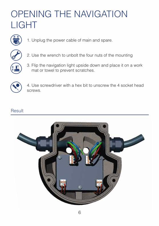
OPENING THE NAVIGATION LIGHT
1. Unplug the power cable of main and spare.
2. Use the wrench to unbolt the four nuts of the mounting
3. Flip the navigation light upside down and place it on a work mat or towel to prevent scratches.
4. Use screwdriver with a hex bit to unscrew the 4 socket head screws.
6
Result
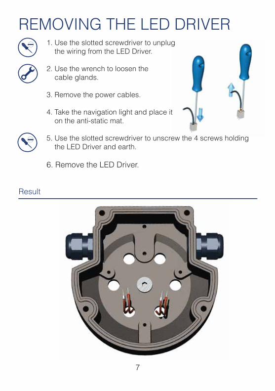
REMOVING THE LED DRIVER1. Use the slotted screwdriver to unplug the wiring from the LED Driver.
2. Use the wrench to loosen the cable glands.
3. Remove the power cables.
4. Take the navigation light and place it on the anti-static mat.
5. Use the slotted screwdriver to unscrew the 4 screws holding the LED Driver and earth.
6. Remove the LED Driver.
7
Result
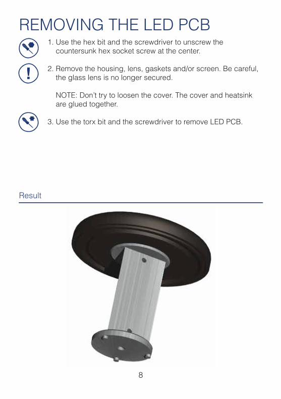
REMOVING THE LED PCB1. Use the hex bit and the screwdriver to unscrew the countersunk hex socket screw at the center.
2. Remove the housing, lens, gaskets and/or screen. Be careful, the glass lens is no longer secured.
NOTE: Don’t try to loosen the cover. The cover and heatsink are glued together.
3. Use the torx bit and the screwdriver to remove LED PCB.
8
Result
!
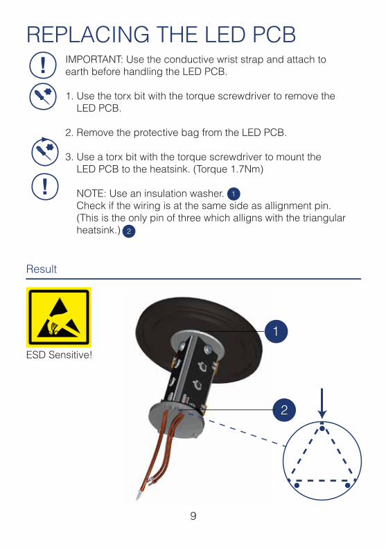
REPLACING THE LED PCBIMPORTANT: Use the conductive wrist strap and attach to earth before handling the LED PCB.
1. Use the torx bit with the torque screwdriver to remove the LED PCB.
2. Remove the protective bag from the LED PCB.
3. Use a torx bit with the torque screwdriver to mount the LED PCB to the heatsink. (Torque 1.7Nm)
NOTE: Use an insulation washer. Check if the wiring is at the same side as allignment pin. (This is the only pin of three which alligns with the triangular heatsink.)
9
1
2
1
2
Result
!
!
ESD Sensitive!
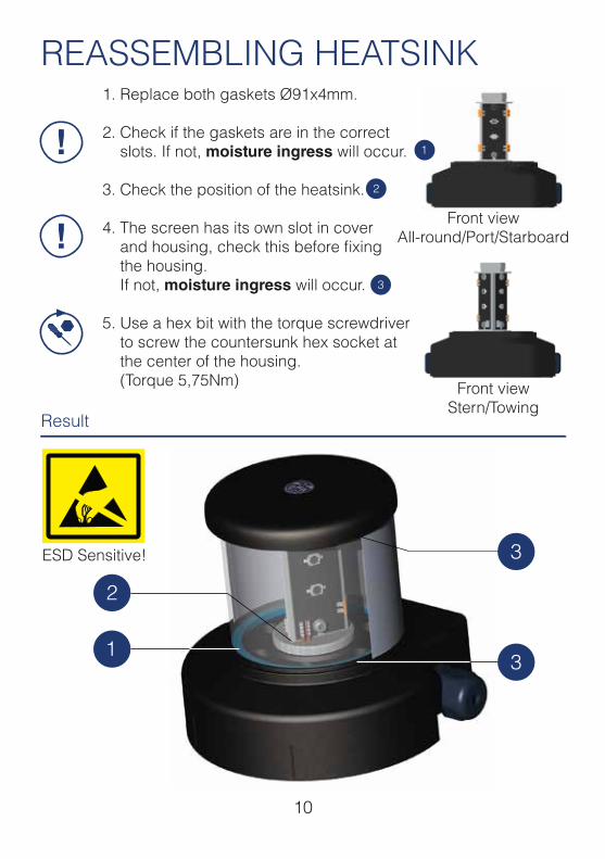
REASSEMBLING HEATSINK1. Replace both gaskets Ø91x4mm.
2. Check if the gaskets are in the correct slots. If not, moisture ingress will occur.
3. Check the position of the heatsink.
4. The screen has its own slot in cover and housing, check this before fixing the housing. If not, moisture ingress will occur.
5. Use a hex bit with the torque screwdriver to screw the countersunk hex socket at the center of the housing. (Torque 5,75Nm) Front view
Stern/Towing
Front viewAll-round/Port/Starboard
10
1
2
3
1
2
3
3
Result
!
!
ESD Sensitive!
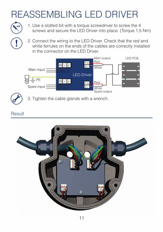
REASSEMBLING LED DRIVER1. Use a slotted bit with a torque screwdriver to screw the 4 screws and secure the LED Driver into place. (Torque 1,5 Nm)
2. Connect the wiring to the LED Driver. Check that the red and white ferrules on the ends of the cables are correctly installed in the connector on the LED Driver.
3. Tighten the cable glands with a wrench.
11
Result
!
PE
LED PCB
12Spare input
Main input
1 +2 -
PE - +
121 +2 -PE - +
Ÿ Use the fitting screw driver to screw the four screws Ÿ Connect the wiring to the power supply
Tighten the cable glands of the power cables
Result
LED-Driver
Red
White
Red
White
Main output
Spare output

CLOSING THE LIGHT1. Replace the base plate gasket.
2. Screw the four hex socket screws of the base plate in the housing with a hex bit and the torque screwdriver. (Torque 3Nm)
3. Bolt the navigation light to the mounting plate with a torque wrench. (Torque 6-8Nm) NOTE: Always use the insulation washers to prevent galvanic corrosion.
12
Result
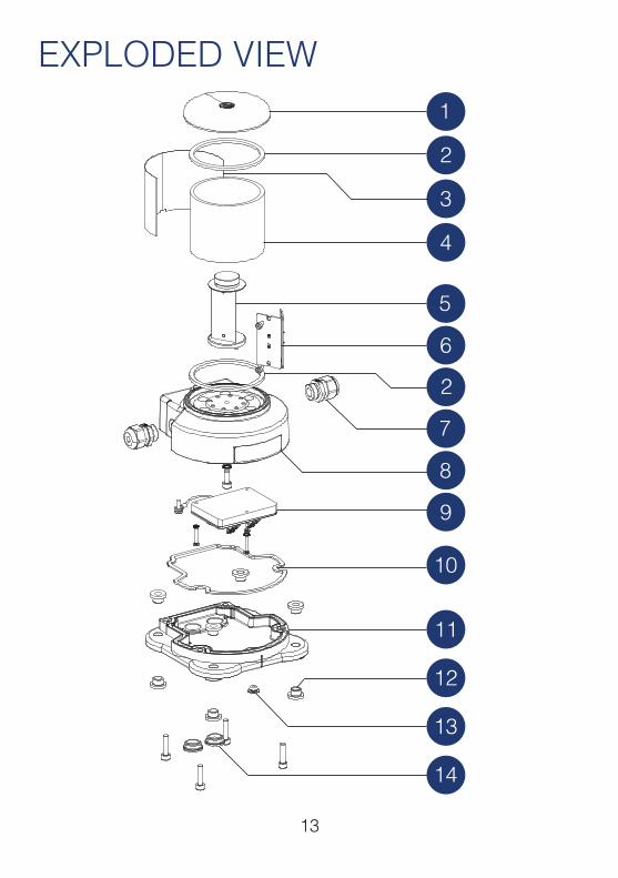
1
2
8
14
3
4
5
6
2
7
9
10
11
13
12
EXPLODED VIEW
13
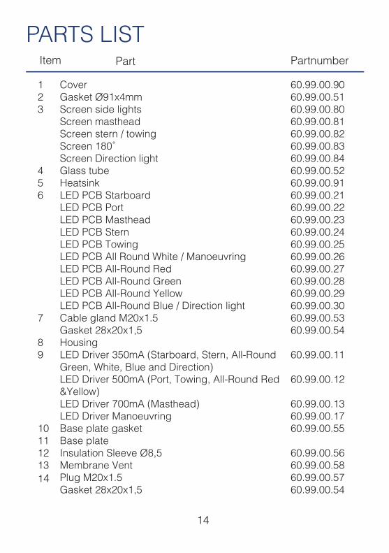
Item Part Partnumber
123
456
7
89
1011121314
CoverGasket Ø91x4mmScreen side lightsScreen mastheadScreen stern / towingScreen 180˚Screen Direction lightGlass tubeHeatsink LED PCB StarboardLED PCB PortLED PCB MastheadLED PCB SternLED PCB TowingLED PCB All Round White / ManoeuvringLED PCB All-Round RedLED PCB All-Round GreenLED PCB All-Round YellowLED PCB All-Round Blue / Direction lightCable gland M20x1.5Gasket 28x20x1,5HousingLED Driver 350mA (Starboard, Stern, All-Round Green, White, Blue and Direction)LED Driver 500mA (Port, Towing, All-Round Red &Yellow)LED Driver 700mA (Masthead)LED Driver ManoeuvringBase plate gasketBase plateInsulation Sleeve Ø8,5Membrane VentPlug M20x1.5Gasket 28x20x1,5
60.99.00.9060.99.00.5160.99.00.8060.99.00.8160.99.00.8260.99.00.8360.99.00.8460.99.00.5260.99.00.9160.99.00.2160.99.00.2260.99.00.2360.99.00.2460.99.00.2560.99.00.2660.99.00.2760.99.00.2860.99.00.2960.99.00.3060.99.00.5360.99.00.54
60.99.00.11
60.99.00.12
60.99.00.1360.99.00.1760.99.00.55
60.99.00.5660.99.00.5860.99.00.5760.99.00.54
PARTS LIST
14
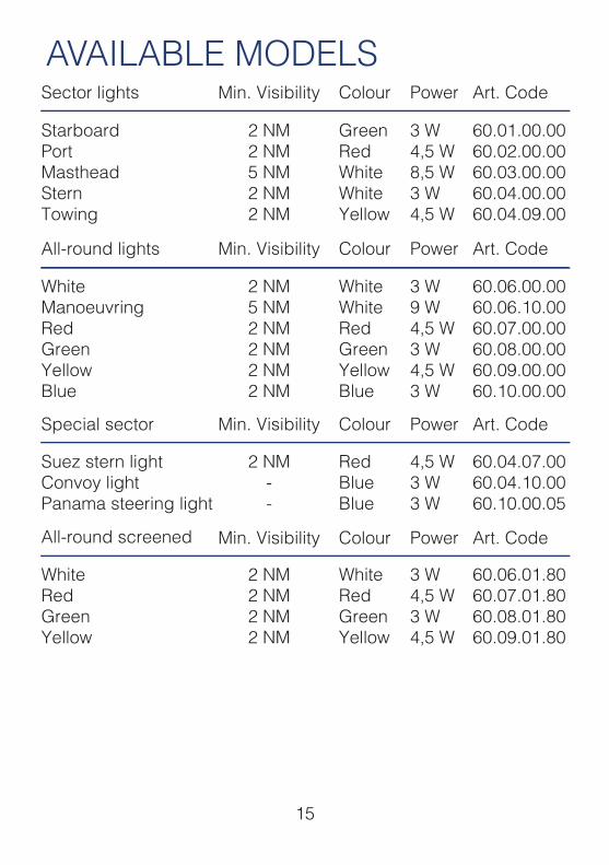
AVAILABLE MODELS
All-round screened
Sector lights
Min. Visibility
Min. Visibility
Colour
Colour
Art. Code
Art. CodePower
StarboardPortMastheadSternTowing
2 NM2 NM5 NM2 NM2 NM
GreenRedWhiteWhiteYellow
60.01.00.0060.02.00.0060.03.00.0060.04.00.0060.04.09.00
3 W4,5 W8,5 W3 W4,5 W
Suez stern lightConvoy lightPanama steering light
2 NM--
RedBlueBlue
60.04.07.0060.04.10.0060.10.00.05
4,5 W3 W3 W
WhiteRedGreenYellow
2 NM2 NM2 NM2 NM
WhiteRedGreenYellow
60.06.01.8060.07.01.8060.08.01.8060.09.01.80
3 W4,5 W3 W4,5 W
Special sector Min. Visibility Colour Art. CodePower
Power
WhiteManoeuvringRedGreenYellowBlue
2 NM5 NM2 NM2 NM2 NM2 NM
WhiteWhiteRedGreenYellowBlue
60.06.00.0060.06.10.0060.07.00.0060.08.00.0060.09.00.0060.10.00.00
3 W9 W4,5 W3 W4,5 W3 W
All-round lights Min. Visibility Colour Art. CodePower
15
SINCE 1922
Den Haan RotterdamFascinatio Boulevard 11822909 VA Capelle a/d IJsselT +31 (0) 10 41 30 755E [email protected]
ADVANCED MARITIME SIGNALLING SOLUTIONS