Embed Size (px)
Citation preview
Dielectric Elastomer Spring Roll Actuators fora Portable Force Feedback Device
Rui Zhang∗
Swiss Federal Institute of Technology (ETH)Center of Product Development
Tannenstrasse 3, 8092 Zurich, Switzerland
Andreas Kunz†
Swiss Federal Institute of Technology (ETH)Institute of Machine Tools and Manufacturing
Tannenstrasse 3, 8092 Zurich, Switzerland
Patrick Lochmatter‡
Swiss Federal Laboratoriesfor Materials Testing and Research (Empa)Laboratory for Materials and Engineering
Ueberlandstrasse 1298600 Duebendorf, Switzerland
Gabor Kovacs §
Swiss Federal Laboratoriesfor Materials Testing and Research (Empa)Laboratory for Materials and Engineering
Ueberlandstrasse 1298600 Duebendorf, Switzerland
ABSTRACT
In this paper, we present a new portable force feedback device forsurgery simulations. Dielectric elastomer spring roll linear actua-tors for this device were manufactured, and characterized via pas-sive tensile tests and active isometric tests. The actuators exhibiteda maximum force of 7.2 N, and a maximum elongation of 31%.Due to the high driving voltage, electrical safety issues were alsoconsidered. The results showed that sufficient electrical safety canbe provided to the user. Two prototypes were built, which practi-cally showed functionalities of the actuator and the proposed forcefeedback concept with actuators connected between the fingers.
CR Categories: H.5.2 [Information Interfaces and Presenta-tion]: User Interfaces—Haptic I/O; H.1.2 [Models and Principles]:User/Machine Systems—Human Factors
Keywords: force feedback, actuator, dielectric elastomer, electri-cal safety
1 INTRODUCTION
The design of a force feedback device is always an application-oriented task due to the complex haptic sensation of human beingsand the limitation of the nowadays actuation technologies. Thisholds also true for the development of a force feedback device foropen surgery simulations.
Our study shows that surgeons use their hands 22− 26% of thewhole operation time to touch the body of a patient, to define theoperation area, or to find, hold and to palpate the organ [22]. Fromthe organ palpation, surgeons receive precise haptic information ofthe organ such as texture, temperature, humidity, stiffness, etc. Thefingertips of the index, the middle finger, and the thumb are mainlyinvolved in this process. According to the classification of graspinggeometries [7], this action belongs to the precision grasping.
Force feedback devices used for grasping simulations can gener-ally be classified into ground-based and body-based types accord-ing to the location of the device. The former is fixed to its envi-ronment such as desk, ceiling, wall, or floor, while the latter has itsground on the user’s body.
∗e-mail:[email protected]†e-mail:[email protected]‡e-mail:[email protected]§e-mail:[email protected]
Some of the ground-based devices are based on stylus appara-tus such as PHANTOM [21] or Delta [16]. In order to study vi-sual recalibration aided by haptic cues, Atkins et al [3] have usedtwo PHANTOMs, allowing a user to grasp virtual objects with histhumb and index finger.
Barbagli et al [4] have attached additional force reflecting grip-pers to two PHANTOMs, which enable multi-finger, dual-hand ex-plorations of virtual objects.
The advent of these ground-based devices enable users to in-tuitively grasp and manipulate virtual objects. However, implicitfriction and backlash from the series design, limited workspace,absence of portability, and high cost of two complete systems aretheir drawbacks.
Body-based devices are portable and provide more workspace tousers in virtual environments (VE). These devices provide forcesonto the fingertips, either from the dorsal side, or from the palmarside of the hand.
Stergiopoulos et al [13] have developed a two-finger hand ex-oskeleton with 2 active degrees of freedom (DOF). The device isdriven by DC motors that are located at the metacarpophalangeal(MCP) joints. Forces are transmitted onto each fingertip via a cable-pulley mechanism.
Instead of positioning the actuators on the hand, CyberGrasp[18] has 5 electric actuators located remotely from the hand. Theirforces are transmitted onto the fingertips via a cable-pulley systemas well.
Using ultrasonic actuators, Choi et al [6] have designed a handexoskeleton with a 4-bar mechanism transmitting the forces ontothe fingertips.
Bouzit et al [5] have developed Rutgers Master II with four pneu-matic actuators located between the palm and the fingers (exceptfor the little finger). This structure requires no force transmissionmechanism (kinematic-free), and provides forces directly onto fin-gertips, where contact forces are necessary.
Compared to ground-based devices, portable devices enableusers to interact with virtual objects in a more intuitive way. How-ever, the portability is achieved at the sacrifice of their ergonomics.
Force transmission mechanisms can be found in both types ofdevices. Such mechanisms result in bulky, and mechanically com-plex systems with high inertia and high internal frictions. It fur-ther induces an obscuring of the effective feedback force (actuatorforce/system friction). The adjustment of such mechanisms to fitdifferent sizes of hands is time-consuming and may cause errors inthe position sensing. Moreover, the attachments of these transmis-sion structures on the hand introduce unwanted forces, which maystrongly disturb the user from concentrating on a task.
In our previous study [9] and [24], we presented a conceptualforce feedback glove with integrated tendon-like actuators on the
347
Symposium on Haptic Interfaces for Virtual Environment and Teleoperator Systems 2006March 25 - 26, Alexandria, Virginia, USA1-4244-0226-3/06/$20.00 ©2006 IEEE
Authorized licensed use limited to: IEEE Xplore. Downloaded on December 6, 2008 at 05:41 from IEEE Xplore. Restrictions apply.
finger’s dorsal side. The tendon-like actuator provide forces onthe fingertips by pulling them backwards. No force transmissionstructure is necessary. An elementary dielectric elastomer (DE) ac-tuator for this concept (active area: 48×30×0.1 mm3) exhibited adisplacement of 7.5 mm and a contractile force of 0.7 N under apre-stretching force of 2 N.
The challenge for such planar DE actuators is the design of ahousing, which should be able to hold biaxial pre-strains in the film(VHB 4910 3M) while allowing one degree of freedom for the ac-tive deformation. We tried both joint-free housings and mechanicalslides with spiral springs. The former was not able to hold the pre-strains completely. The latter strongly reduced the ratio of the activematerial’s mass to the housing’s mass. Due to those difficulties inthe actuator manufacturing and the required external pre-stretchingforce, the application of this tendon-like actuator for the proposedforce feedback glove was limited.
In this study, we present a DE spring roll actuator, which hasbeen improved concerning the actuator construction, manufacturingprocess, actuator performance, and its suitability for a new portableforce feedback device. The final goal of this study is to build akinematic-free, lightweight, and portable force feedback device for,but not limited to surgery simulations.
2 CONCEPT STUDY OF GLOVE-LIKE FORCE FEEDBACKDEVICES
In order to determine the functions of a portable force feedbackdevice, we need to look at the essentials of human-object grasping.
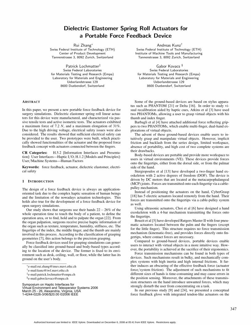
In precision grasping, the index finger, the middle finger, andthe thumb are involved with the contact forces concentrating on thefingertips [7]. The forces from the object act against the finger’sflexion, which is generated by the muscles and tendons in the handand the forearm (see Figure 1(a)). Here, we assume that the contactforce is normal to the contact surface.
(a) (b)
Figure 1: (a) External resulting forces from the object act againstthe finger flexion in precision grasping and (b) the contact model ofthe finger-device grasping.
To simulate an object grasping in VE, a device must be able toprovide resulting external forces on the contact areas. As shown inFigure 1(b), we take a portable device, which is grounded on thewrist for example. Local actuators with force transmission mecha-nisms are able to provide the required force.
However, there exist constraint forces from the device acting onthe wrist via the attachment A and B. As we mentioned in Sec-tion 1, these unnecessary forces consequently reduce the fidelity ofthe force feedback, since they don’t exist in a real object grasping.Therefore, it is important to moderate the effects of these constraintforces on the user by properly positioning the actuators, properlyselecting and attaching a transmission system to the hand.
2.1 Requirements
In this study, we’ve defined two major functional capabilities fordesigning a transparent [4] force feedback device.
(i) Force feedback capability: The device should be able to gen-erate forces at given contact points, when an interaction be-tween a virtual hand and a virtual object occurs. Here we de-fined one actuator at one contact point as one active DOF. Forthe aforementioned precision grasping, four active DOF arerequired with each for the fingertip of the index, the middle,the ring finger, and the thumb.
(ii) Backdrivablility: The device should have low intrinsic me-chanical impedance, so it can passively follow an imposedmotion from the finger. Extending this definition, a device isalso considered to be backdrivable if it can actively follow theimposed motion. Thus, the user can move their fingers freelywithout perceiving the existence of the device. The DOF ofthe fingers’ motions is defined here as passive DOF. 16 passiveDOF are considered to be enough for the precision graspingsimulation (four for each finger, except for the little finger).
Detailed functional requirements such as force, elongation,bandwidth, etc. were given in [24]. In addition, ergonomics such asweight, volume, location, and kind of the attachment onto the bodywere considered.
2.2 Concepts for a portable force feedback device in three cat-egories
For portable devices, the fixation of the devices is limited to thehand including the wrist. According to the locations of the actua-tors, we have classified our concepts into three categories: actua-tors on the dorsal side, on the palmar side, and actuators around thefingers. The concepts is briefly analyzed concerning their mechan-ics (distribution of the feedback force and their counter forces fromthe attachments, force direction, etc.), as well as their ergonomicfactors (design space, weight, volume, inertia, friction, etc.).
2.2.1 Actuators on the dorsal side
Most of the existing portable devices belong to this group, such asthe above mentioned CyberGrasp, the 2-finger hand exoskeleton,and the ultrasonic based hand exoskeleton. The devices provideforces onto the fingertips by pulling them backwards, either hav-ing the actuators integrated in the exoskeleton or remotely located.Additional force transmission mechanisms are required for intro-ducing the actuator forces normal to the fingertips.
To avoid any force transmission, we can attach tendon-like DEactuators on the finger’s back [24], or integrate such actuators in aprotagonist-antagonist mechanism over the fingers. A lightweightand concise structure can therefore be reached. However, the forceacts more along the finger axis than normal to the fingertip. Ob-viously, bulky force transmission mechanism and a realistic forcebecome a tricky trade-off in this category.
One advantage of this group is their large design space on thedorsal side. Depending on their force transmissions, they could bekinematic-free, and provide wide area feedbacks [8]. The actua-tors can be individually controlled, which allows rich simulationmetaphors.
2.2.2 Actuators on the palmar side
Instead of pulling the fingers backwards, the actuators in this cat-egory provide forces onto the fingertips by pushing against them.They can be attached between the thumb and other fingers, between
348
Authorized licensed use limited to: IEEE Xplore. Downloaded on December 6, 2008 at 05:41 from IEEE Xplore. Restrictions apply.
the finger phalanxes, between the fingers and the palm (such as Rut-ger Master II), or between the fingers and the wrist, respectively.
Compared with the category actuators on the dorsal side, thisgroup also allows individual control of the actuators and wide areaforce feedback, but it has less design space. No force transmissionmechanism is required, and thus, it allows a light-weight, and con-cise device with low friction, low inertia, and zero backlash.
Furthermore, some concepts take great use of the countergrounding force and transfer it into the useful feedback forces. Tak-ing the Rutgers Master II for example, it can well simulate power-ful grasping, where the fingers and the palm are involved. There isno unrealistic constraint force (as from force transmission mecha-nisms) that disturbs the users.
One drawback of these systems is the limited simulationmetaphors (either touch or grasping, but not both).
This group contains instability as well. Opposite to the actua-tors on the dorsal side, the actuator and its attachments are undercompressive load. Due to the softness of the fingers and their per-ception constraints, an ideally rigid connection between fingers andactuators is not possible. Furthermore, the compressive force on theactuator is limited by its buckling load. These factors may seriouslydeteriorate the force feedback fidelity.
2.2.3 Actuators around the fingers
In this group the actuators are directly attached around the fingerphalanxes. Such as ring-like actuators or sphincter-like actuators,the actuators provide forces to the fingertips by radially squeezingthe fingers.
Due to the limited ab-/adduction angles of the fingers, there islittle design space. Moreover, the resulting external force from thesphincter-like actuator on the fingertips is almost zero. Accordingto our discussion on the contact model (see Figure 1), we doubtedif this category should be taken into account. Therefore, we madeinitial psychophysical tests in order to find out if the sphincter-likeactuators would provide realistic grasping forces to the user.
A textile band was attached around the subject’s index fingertip.Two ends of this band were held by the examiner. By contractingthese two ends, the examiner can manually ”switch on” (i.e. con-tracting) the part around the finger, and thus squeezing forces wereapplied around the fingertip.
Eight subjects were asked to fulfill the tests. They were not in-formed about the content of the test before. Each subject was askedto follow two phases: Phase I: forces were applied around the fin-gertip without any visual cue to the user, and Phase II: forces wereapplied around the fingertips, while visual cues were given to theuser.
In Phase I, no subject could describe exactly what actually hap-pened on the fingertip. However, in Phase II, seven of the totaleight subjects felt a grasping force on the fingertip. Guided by thevisual cues, the subjects could concentrate on the task of ”graspinga glass”, and were not disturbed by forces at the finger’s dorsal andlateral side.
2.3 Results of the concept study
22 concepts in three categories have been established. Structuremechanics of each concept was studied in order to theoretically es-timate the feedback resp. counter force distributions, and to specifythe actuator requirements. 10 concepts with their feasibilities forDE actuators were selected, and then evaluated using the pair com-parison method [10], out of which 4 solutions have been furtherstudied.
The first rank, and the selected concept in this paper as well, wasin the category actuator between fingers. Four actuators connectdirectly the thumb with other fingers. Such a solution has almostthe same grasping geometry as human beings naturally have. The
working principle of the corresponding DE actuators is introducedin Section 3.
3 SPRING ROLL DE ACTUATORS
Basically, a DE actuator is a compliant capacitor. A thin elas-tomeric film is sandwiched between two compliant electrodes. Un-der activation with a high DC voltage (kV ), the electrostatic pres-sure squeezes the elastomer film in thickness, and thus the incom-pressible film expands in all planar directions.
A DE spring roll actuator consists of biaxially pre-stretched,electrode-coated elastomer films, which are wrapped around anelastic core. The geometry of the core can be varied according to agiven application. By utilizing such a compact structure, the energydensity is significantly enhanced when compared to the foregoingplanar DE actuator. Pei et al [12] [11] have developed multi-DOFDE spring roll linear or bending actuators for multi-leg robots. Hav-ing low buckling strength, the spring roll actuator provides limitedcompressive forces as needed for the selected concept actuator be-tween the fingers.
3.1 Manufacturing of the DE actuator
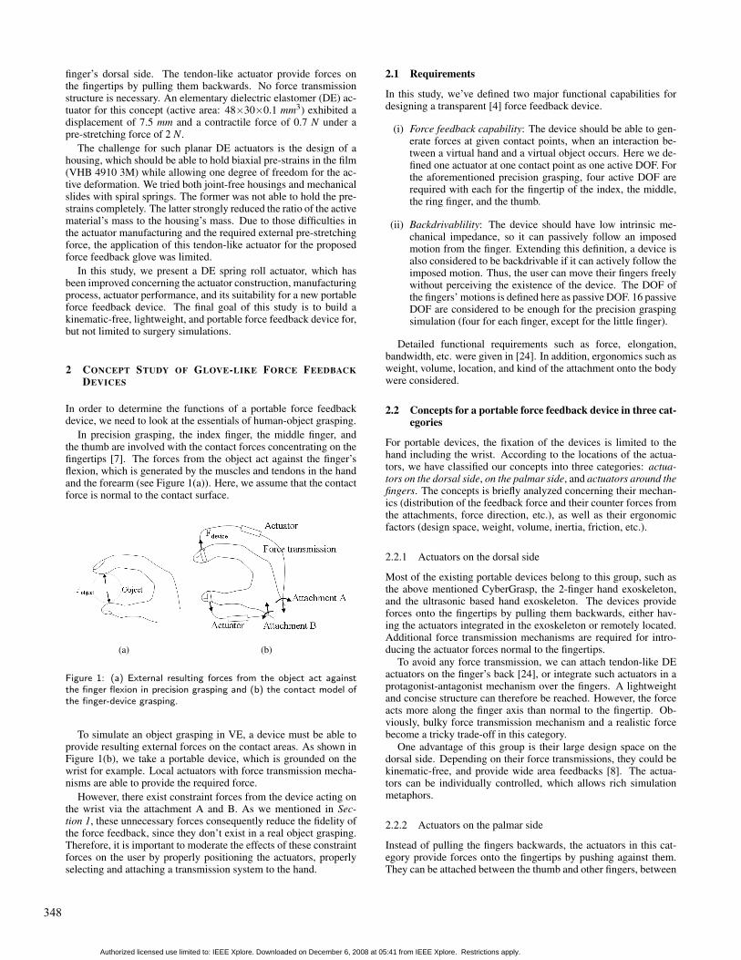
For our application, we enhanced the core by adding a telescopicstructure inside the spring. The DE spring roll linear actuators (seeFigure 2) were produced at Empa Dubendorf [15] based on a half-automated manufacturing process.
Figure 2: The DE spring roll linear actuator made at Empa Duben-dorf.
Major steps of the actuator manufacturing are as follows: au-tomated biaxial pre-stretching of the elastomer film (VHB 49103M), manual coating the films with compliant electrodes, manualwrapping of the pre-stretched film around the fully compressedtelescope-spring core (see Figure 3 Assembly), and lateral fixationof the film on the core.
3.2 Working principle of the DE spring roll linear actuator
Basically, the DE spring roll actuator is an active spring with adap-tive stiffness. Figure 3 schematically shows the working principleof the actuator for a force feedback device with actuators betweenthe fingers. In the force-displacement diagram (see Figure 3), weassume that the employed VHB 4910 elastomer film is incompress-ible, isotropic, and has quasi-linear behavior under the given pre-stretch condition.
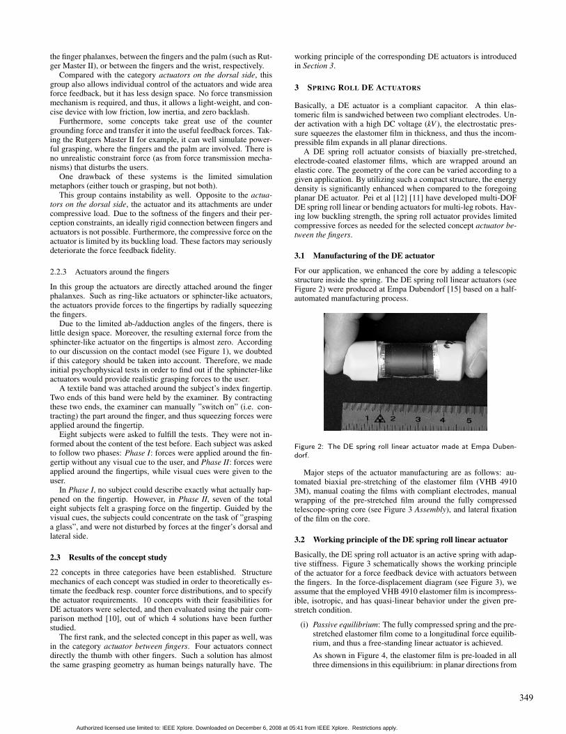
(i) Passive equilibrium: The fully compressed spring and the pre-stretched elastomer film come to a longitudinal force equilib-rium, and thus a free-standing linear actuator is achieved.As shown in Figure 4, the elastomer film is pre-loaded in allthree dimensions in this equilibrium: in planar directions from
349
Authorized licensed use limited to: IEEE Xplore. Downloaded on December 6, 2008 at 05:41 from IEEE Xplore. Restrictions apply.
Figure 3: The working principle of DE spring roll linear actuators forthe proposed force feedback device.
the pre-stretching, and in the film’s thickness direction fromthe wrapping of the film around the cylindric core. An electri-cal voltage acting in the film’s thickness direction brings elec-tromechanical pressure in this direction. This force changesthe force equilibrium state, and therefore the actuator can becontrolled via the electrical voltage.
Figure 4: Force equilibrium of the free-standing actuator and theelectromechanical coupling.
(ii) Free-strain under isotonic activation: If a high voltage is ap-plied to the actuator, electrostatic forces act in the film’s thick-ness. This results in a longitudinal elongation of the film.Consequently, the spring extends until the film and the springget to a new force equilibrium called activated equilibrium.This motion is reversible when turning off the voltage. Thefree-strain enables the device to actively follow a finger’s mo-tion (backdrivability).
(iii) Blocking force under isometric activation: In the passiveequilibrium, if the actuator’s length is kept constant, and avoltage is applied to the actuator, the tensile force from thefilm decreases, and the spring tends to elongate. The resultingforce can act against an external constraint (e.g. the finger)and is called blocking force of the actuator.
The free-strain and blocking force are two major characteristicsfor such an actuator. By varying the applied activation voltage and
the actuator’s boundary condition, all states within the shaded areain Figure 3 can be actively achieved.
3.3 Characterization of the DE spring roll linear actuator
In order to determine performances of the actuator, passive uniaxialtensile tests and isometric tests under activation were performed.
3.3.1 Measurement setup
As shown in Figure 5, we attached one side of the actuator to thegrounded-frame, and the other side to a force sensor (HBM U2B[17]), which is mounted on a pneumatic cylinder (BRAMATI [15]).The displacement of the actuator was measured by the laser sensor(OADM20I6460/S1 4F, [14]). The measurement signals are con-trolled by LabView via an optoelectronic coupler [20] and a dataacquisition card (BNC 2090 [19]).
Figure 5: Setup of the tensile and isometric tests.
3.3.2 Measurements
In the passive uniaxial tensile tests, the actuator was stretched bythe pneumatic cylinder from its free-standing length to 10 mm withan elongation rate of 2 mm/min. The tensile force of the actuatorwas measured.
During the isometric test under activation, two control signalswere given by LabView: a DC activation voltage (provided byPS350, Stanford Research Systems) for the actuator, and a displace-ment control for the pneumatic cylinder. First, the actuator was keptin its passive equilibrium length. To avoid electrical breakdowncaused by an overshooting voltage from a square activation signal,a DC activation voltage was linearly increased from 0 to 3.5 kVwithin 90 s and applied to the actuator. The compressive blockingforce from the actuator was measured.
Second, the actuator was stretched to 1 mm with an elongationrate of 2 mm/min. While keeping this distance and applying againthe voltage up to 3.5 kV , the longitudinal force was measured. Thisstep was repeated by stretching the actuator each time 1 mm more,until a maximum displacement of 10 mm was reached.
3.3.3 Results
We tested 30 actuators in different groups with slight differences inconstructions and aging (due to the viscosity of the elastomer film).All results show a quasi-linear force-displacement behavior of theactuators. As shown in Figure 6, the measured force decreased asthe linearly increasing voltage was applied for all initial pre-strainsin the range of 0-10 mm. At the original length of the actuator,this force varied in negative range (thrust). As we increased thedisplacement of the actuator, the force varied from negative area
350
Authorized licensed use limited to: IEEE Xplore. Downloaded on December 6, 2008 at 05:41 from IEEE Xplore. Restrictions apply.
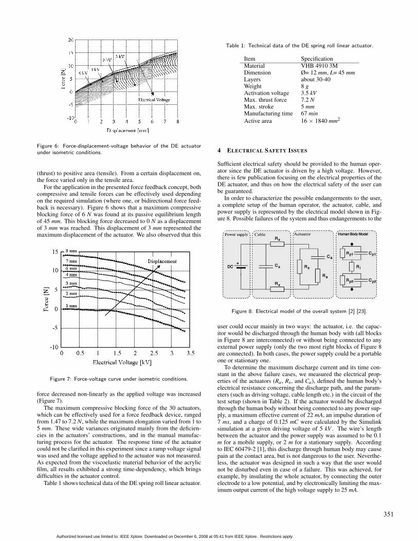
Figure 6: Force-displacement-voltage behavior of the DE actuatorunder isometric conditions.
(thrust) to positive area (tensile). From a certain displacement on,the force varied only in the tensile area.
For the application in the presented force feedback concept, bothcompressive and tensile forces can be effectively used dependingon the required simulation (where one, or bidirectional force feed-back is necessary). Figure 6 shows that a maximum compressiveblocking force of 6 N was found at its passive equilibrium lengthof 45 mm. This blocking force decreased to 0 N as a displacementof 3 mm was reached. This displacement of 3 mm represented themaximum displacement of the actuator. We also observed that this
Figure 7: Force-voltage curve under isometric conditions.
force decreased non-linearly as the applied voltage was increased(Figure 7).
The maximum compressive blocking force of the 30 actuators,which can be effectively used for a force feedback device, rangedfrom 1.47 to 7.2 N, while the maximum elongation varied from 1 to5 mm. These wide variances originated mainly from the deficien-cies in the actuators’ constructions, and in the manual manufac-turing process for the actuator. The response time of the actuatorcould not be clarified in this experiment since a ramp voltage signalwas used and the voltage applied to the actuator was not measured.As expected from the viscoelastic material behavior of the acrylicfilm, all results exhibited a strong time-dependency, which bringsdifficulties in the actuator control.
Table 1 shows technical data of the DE spring roll linear actuator.
Table 1: Technical data of the DE spring roll linear actuator.
Item SpecificationMaterial VHB 4910 3MDimension Ø= 12 mm, L= 45 mmLayers about 30-40Weight 8 gActivation voltage 3.5 kVMax. thrust force 7.2 NMax. stroke 5 mmManufacturing time 67 minActive area 16 × 1840 mm2
4 ELECTRICAL SAFETY ISSUES
Sufficient electrical safety should be provided to the human oper-ator since the DE actuator is driven by a high voltage. However,there is few publication focusing on the electrical properties of theDE actuator, and thus on how the electrical safety of the user canbe guaranteed.
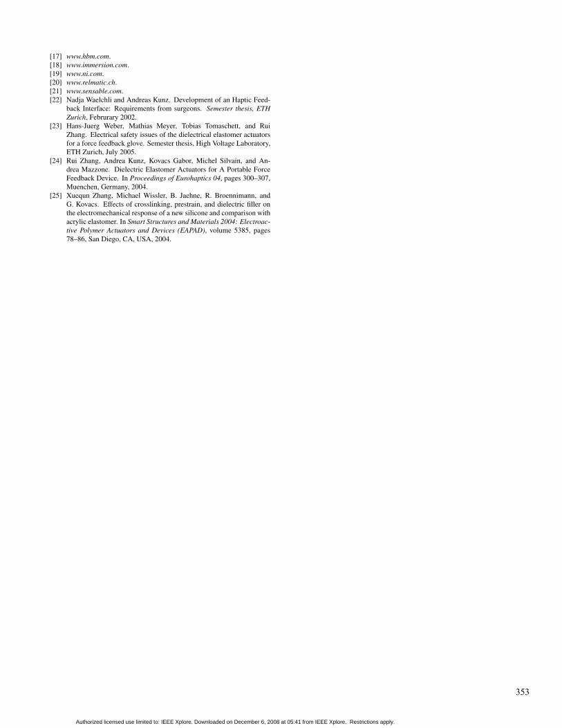
In order to characterize the possible endangerments to the user,a complete setup of the human operator, the actuator, cable, andpower supply is represented by the electrical model shown in Fig-ure 8. Possible failures of the system and thus endangerments to the
Figure 8: Electrical model of the overall system [2] [23].
user could occur mainly in two ways: the actuator, i.e. the capac-itor would be discharged through the human body with (all blocksin Figure 8 are interconnected) or without being connected to anyexternal power supply (only the two most right blocks of Figure 8are connected). In both cases, the power supply could be a portableone or stationary one.
To determine the maximum discharge current and its time con-stant in the above failure cases, we measured the electrical prop-erties of the actuators (Ra, Rs, and Ca), defined the human body’selectrical resistance concerning the discharge path, and the param-eters (such as driving voltage, cable length etc.) in the circuit of thetest setup (shown in Table 2). If the actuator would be dischargedthrough the human body without being connected to any power sup-ply, a maximum effective current of 22 mA, an impulse duration of7 ms, and a charge of 0.125 mC were calculated by the Simulinksimulation at a given driving voltage of 5 kV . The wire’s lengthbetween the actuator and the power supply was assumed to be 0.1m for a mobile supply, or 2 m for a stationary supply. Accordingto IEC 60479-2 [1], this discharge through human body may causepain at the contact area, but is not dangerous to the user. Neverthe-less, the actuator was designed in such a way that the user wouldnot be disturbed even in case of a failure. This was achieved, forexample, by insulating the whole actuator, by connecting the outerelectrode to a low potential, and by electronically limiting the max-imum output current of the high voltage supply to 25 mA.
351
Authorized licensed use limited to: IEEE Xplore. Downloaded on December 6, 2008 at 05:41 from IEEE Xplore. Restrictions apply.
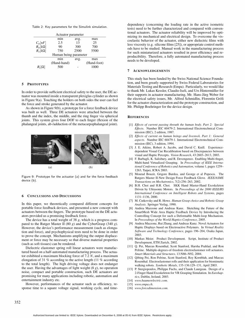
Table 2: Key parameters for the Simulink simulation.
Actuator parametermin avg. max
Ca[nF ] 2.5 13 25Ra[kΩ] 90 300 700Rs[kΩ] 750 2500 5500
Human being parametermin avg. max
(Hand-hand) (Hand-foot)Ri[Ω] 500 - 1000
5 PROTOTYPES
In order to provide sufficient electrical safety to the user, the DE ac-tuator was mounted inside a transparent plexiglas cylinder as shownin Figure 9(a). Touching the holders on both sides the user can feelthe force and stroke generated by the actuator.
As shown in Figure 9(b), a prototype for a force feedback devicewas built as well. Three DE actuators were attached between thethumb and the index, the middle, and the ring finger via sphericaljoints. This system gives four DOF to each finger (flexion of thephalangeal joints, ab-/adduction of the metacarpophalangeal joint).
(a) (b)
Figure 9: Prototype for the actuator (a) and for the force feedbackdevice (b).
6 CONCLUSIONS AND DISCUSSIONS
In this paper, we theoretically compared different concepts forportable force feedback devices, and presented a new concept withactuators between the fingers. The prototype based on the DE actu-ators provided us a promising feedback force.
The device has a total weight of 38 g, which is a progress com-pared to the Rutger Master II (80 g) and the CyberGrasp (340 g).However, the device’s performance measurement (such as elonga-tion and force), and psychophysical tests need to be done in orderto prove the concept. Mechanisms amplifying the output displace-ment or force may be necessary so that diverse material properties(such as soft tissues) can be rendered.
Dielectric elastomer spring roll linear actuators were manufac-tured based on a half-automated manufacturing process. The actua-tor exhibited a maximum blocking force of 7.2 N, and a maximumelongation of 31 % according to the active length (11 % accordingto the total length). The high driving voltage does not endangerthe user. Having the advantages of light weight (8 g), no operationnoise, compact and portable construction, such DE actuators arepromising for many applications including robotic, automation andentertainment industry etc.
However, performances of the actuator such as efficiency, re-sponse time to a square voltage signal, working cycle, and time-
dependency (concerning the loading rate in the active isometrictests) need to be further characterized and compared with conven-tional actuators. The actuator reliability will be improved by opti-mizing its mechanical and electrical design. To overcome the vis-coelastic behavior of the actuator, either new dielectric films withless viscosity (e.g. silicone films [25]), or appropriate control meth-ods have to be studied. Manual work in the manufacturing processfor such miniaturized actuators resulted in poor efficiency and re-producibility. Therefore, a fully automated manufacturing processneeds to be developed.
7 ACKNOWLEDGEMENTS
This study has been funded by the Swiss National Science Founda-tion, and been greatly supported by Swiss Federal Laboratories forMaterials Testing and Research (Empa). Particularly, we would liketo thank Mr. Lukas Kessler, Claudio Iseli, and Urs Hintermuller fortheir supports in actuator manufacturing, Mr. Hans-Jurg Weber forthe electrical safety issues, Mr. Alfred Schmidlin, Florentin Grolifor the actuator characterization and the prototype construction, andMr. Philipp Boehringer for the device design.
REFERENCES
[1] Effects of current passing throuth the human body. Part 2: SpecialEffects. Number IEC 60479-2. International Electrotechnical Com-mission (IEC), 2 edition, 1987.
[2] Effects of current on human beings and livestock. Part 1: Generalaspects. Number IEC 60479-1. International Electrotechnical Com-mission (IEC), 3 edition, 1994.
[3] J. E. Atkins, Robert A. Jacobs, and David C. Knill. Experience-dependent Visual Cue Recalibration based on Discrepancies betweenvisual and Haptic Percepts. Vision Research, 43:2603–2613, 2003.
[4] F. Barbagli, K. Salisbury, and R. Devengenzo. Enabling Multi-finger,Multi-hand Virtualized Grasping. In Proceedings of IEEE Interna-tional Conference of Robotics and Automation, volume 1, pages 1259–1263, Taipei, ICRA 2003.
[5] Mourad Bouzit, Grigore Burdea, and George et al Popescu. TheRutgers Master II-New Design Force Feedback Glove. IEEE/ASMETransactions on Mechatronics, 7(2):256–263, 2002.
[6] B.H. Choi and H.R. Choi. SKK Hand Master-Hand ExoskeletonDriven by Ultrasonic Motors. In Proceedings of the 2000 IEEE/RSInternational Conference on Intelligent Robots and Systems, pages1131–1136, 2000.
[7] M. Cutkovsky and R. Howe. Human Grasp choice and Robotic GraspAnalysis. Springer Verlag, 1990.
[8] Andrea Mazzone and Andreas Kunz. Sketching the Future of theSmartMesh Wide Area Haptic Feedback Device by Introducing theControlling Concept for such a Deformable Multi-loop Mechanism.In Proceedings of the World Haptics Conference, 2005.
[9] Andrea Mazzone, Rui Zhang, and Andreas Kunz. Novel Actuators forHaptic Displays based on Electroactive Polymers. In Virtual RealitySoftware and Technology Conference, pages 196–204, Osaka Japan,2003.
[10] Markus Meier. Product Development. Script, Institute of ProductDevelopment, ETH Zurich, 2002.
[11] Q. Pei, Marcus Rosenthal, Scott Stanford, Harsha Prahlad, and RonPelrine. Multiple-degrees-of-freedom electroelastomer roll actuators.Smart Materials and Structures, 13:N86–N92, 2004.
[12] Qibing Pei, Ron Pelrine, Scott Stanford, Roy Kornbluh, and MarcusRosenthal. Electroelastomer rolls and their application for biomimeticwalking robots. Synthetic Metals, 135-136:129–131, April 2003.
[13] P. Stergiopoulos, Philippe Fuchs, and Claude Laurgeau. Design of a2-Finger Hand Exoskeleton for VR Grasping Simulation. In Eurohap-tics, Dublin, Ireland, 2003.
[14] www.baumerelectric.com.[15] www.empa.ch.[16] www.forcedimension.com.
352
Authorized licensed use limited to: IEEE Xplore. Downloaded on December 6, 2008 at 05:41 from IEEE Xplore. Restrictions apply.
[17] www.hbm.com.[18] www.immersion.com.[19] www.ni.com.[20] www.relmatic.ch.[21] www.sensable.com.[22] Nadja Waelchli and Andreas Kunz. Development of an Haptic Feed-
back Interface: Requirements from surgeons. Semester thesis, ETHZurich, Februrary 2002.
[23] Hans-Juerg Weber, Mathias Meyer, Tobias Tomaschett, and RuiZhang. Electrical safety issues of the dielectrical elastomer actuatorsfor a force feedback glove. Semester thesis, High Voltage Laboratory,ETH Zurich, July 2005.
[24] Rui Zhang, Andrea Kunz, Kovacs Gabor, Michel Silvain, and An-drea Mazzone. Dielectric Elastomer Actuators for A Portable ForceFeedback Device. In Proceedings of Eurohaptics 04, pages 300–307,Muenchen, Germany, 2004.
[25] Xuequn Zhang, Michael Wissler, B. Jaehne, R. Broennimann, andG. Kovacs. Effects of crosslinking, prestrain, and dielectric filler onthe electromechanical response of a new silicone and comparison withacrylic elastomer. In Smart Structures and Materials 2004: Electroac-tive Polymer Actuators and Devices (EAPAD), volume 5385, pages78–86, San Diego, CA, USA, 2004.
353
Authorized licensed use limited to: IEEE Xplore. Downloaded on December 6, 2008 at 05:41 from IEEE Xplore. Restrictions apply.


![Silicone rubbers for dielectric elastomers with improved ......dielectric elastomer (DE) formulation due to their favorable electro-mechanical properties. [1] Dielectric elastomers](https://img.pdfslide.net/doc/110x75/60a7aa8430c09b569000940a/silicone-rubbers-for-dielectric-elastomers-with-improved-dielectric-elastomer.jpg)

![Muscle-like high-stress dielectric elastomer actuators ... · to various failure modes as shown in Fig. 1(a), for examples: partial discharge[11], electromechanical instability[12,](https://img.pdfslide.net/doc/110x75/606fef72549e5f1ee437ed9c/muscle-like-high-stress-dielectric-elastomer-actuators-to-various-failure-modes.jpg)