Embed Size (px)
Citation preview
D I F F E R E N C E S B E T W E E N A C O U S T I C A L I N S U L A T I O N P R O P E R T I E S M E A S U R E D I N T H E L A B O R A T O R Y A N D
R E S U L T S O F M E A S U R E M E N T S I N S I T U *
JUDITH LANG
Versuchsanstalt ft'ir W6rme- und Schalltechnik, TGH, Viem~a and Forschungsgesellschaft fiir Wohnen, Bauen und Planen, Vienna (Austria)
(Received : 29 March, 1971)
SUMMA R Y
The writer examines all the causes of rariations in insulation properties measured in the laboratory and in the field, i.e. eotmections, locations, flanking walls, doors, windows, eqttipment and workmanship.
INTRODUCTION
Sound insulation requirements in residential buildings were investigated twenty years ago in several papers and requirements or recommendations for sound insulation of walls and ceilings were established at that time in most countries. There are two different sets of measurements necessary, one to predict the properties of the construction (laboratory measurements of construction specimens) and the other to check whether the requirements are fulfilled in the building. These are:
(I) The measurement of the sound reduction index of a certain wall or ceiling in the laboratory, where air-borne sound reduction index is defined as:
Nl R = !0 log ~22 dB ( l )
Where NI = sound energy incident on the wall in the source room and N 2 ---
s o u n d energy emitted from the wall into the receiving room. (2) The measurement of the sound insulation between two adjacent rooms,
separated by a wall or ceiling. Here R is given by eqn. (2):
S R = LI - L2 + 101og~ dB (2)
* Paper given at CIB Acoustics Working Commission Meeting held in Paris on 15 and 16 April, 1970.
21 Applied Acoustfcs (5) (1972)--O Applied Science Publishers Lid, England--Printed in Great Britain
22 JUDITH LANG
where L t = sound pressure level in the source room, L z = sound pressure level in the receiving room, S = area of the wall or ceiling and A = sound absorption area in the receiving room.
This formula is derived from the first one under conditions of a diffuse sound field and sound transmission only through the wall or ceiling.*
In laboratory measurements only the sound insulation given by the wall to be tested is measured, i.e. the sound transmission through by-passes must be avoided (see ISO Recommendation R140--4-1: 'The sound transmitted by an indirect path should be negligible compared with the sound transmitted through the test specimen').
In buildings, however, a complex sound transmission is given: (a) by the partition wall itself; (b) by the flanking walls; (c) through windows and doors and (d) through installations (pipes, etc.). Hence, sound insulation between two adjacent rooms separated by a wall is often smaller than that measured in the laboratory for the same wall; later building work may not be carried out as carefully as in the laboratory and an additional diminution of sound insulation therefore results.
RESULTS OF LABORATORY MEASUREMENTS
Results of laboratory measurements obtained under defined conditions show differences, i.e. sound insulations of walls vary sometimes even in laboratories under the most favourable conditions, where flanking transmission, by-passes and careless workmanship are excluded. These differences are caused by different edge conditions, as discussed below.
Connection of partition wall to flanking wall According to the way in which the partition wall is connected to the flanking
walls more or less e~nergy flows off and the sound insulation is accordingly higher or lower. Theoretical investigations 2 have shown that the sound insulation of single walls below the critical frequency is not dependent on the dimensions of the wall and its conditions; above the critical frequency, however, the sound insulation is strongly influenced by the energy loss to the flanking walls and the dimensions of the wall. The edge conditions can be described by the absorption coefficient for bending waves, which depends on the properties of test and flanking walls.
Measurements showed that the sound insulation of heavy single walls (400 kg/m 2) is 4 to 8 dB higher compared with calculations which consider only the damping in the material. However, the measurements compare well with calcula- tions presupposing energy loss to the flanking walls, a Measurements on a 23 cm
* According to ISO Recommendation R 140 the quantity R is primarily defined as 10 log NdN2; from which extn. (2) can be derived. However, since the conditions assumed cannot be guaranteed in all cases, the quantity R has been defined directly by exln. (2).
DIFFERENCES BETWEEN ACOUSTICAL INSULATION PROPERTIES 23
brick wall with plaster on both sides, carried out in two laboratories, gave air-borne sound insulation indices differing by 8 dB. 4
Material with high internal damping A material with high internal damping between test wall and flanking walls
contributes in damping the wall and, consequently, raises its sound insulation. 3
Location of test wall The location of the test wall in the test room and the tightness of the edges may
influence the sound insulation, especially with displaceable multi-layer walls without plaster. Thus the same double leaf wall (wooden panels) gave different sound insulation indices (I~ = 45 to 50 dB) depending on the location of the connection to the flanking walls of the test room separated by an air space; three different methods of tightening a double leaf wall to the test room gave sound insulation indices I, = 47 to 55 dB and, therefore, differences of 8 dB. 4
Sound transmission in flanking walls Although sound transmission in flanking walls is completely avoided by an
air space, sound energy is transmitted from the flanking wall in the source room to the test wall, or from the test wall to the flanking wall in the receiving room, according to the position of the air space; the amount of the energy transmitted depends on the construction of test and flanking wall and is particularly important in the case where the specific mass of the flanking wall is of the same order or smaller than that of the test wall. This influence is of particular importance when testing walls with limp panels (Vorsatzschalen) which considerably reduce direct sound transmission through the wall.
Limp panels may give an additional sound insulation from 20 to 30 dB, depending on their construction; the sound reduction at the junction of test wall and flanking wall may be I0 to 40 dB; consequently the sound transmission flanking wall to test wall may be predominant.
To ensure uniform measurement results in all laboratories the conditions lbr test rooms (e.g. edge conditions, flanking walls, dimensions of test walls etc.) should be defined as precisely as possible.
VARYING SOUND INSULATION IN LABORATORIES AND BUILDINGS
Differences of sound transmission through the flanking walls are mainly responsible for the different sound insulations in laboratories and buildings. In particular, field values of air-borne sound insulation can be considerably lower than laboratory values, due to energy transmission via flanking walls. 5 These differences depend on the sound insulation, the materials and construction of the partition wall and
24 JUDITH LANG
the flanking walls. This problem became important after the War when lightweight constructions were developed.
Early investigations indicated that the magnitude of the indirect transmission is negligible when the average insulation of the partition wall or ceiling is lower than 50 dB. 5'6'7 However, later, considerable differences were found with joist floors e.g. with joist floors carried on 11 cm brick walls a limit of about 46 dB between superposed rooms was obtained in the medium frequency range, corresponding to a limit of about 53 dB with concrete floors on similar walls, s This example shows the complexity of the problem which has been intensively studied during recent
30
2 0 m _ _
AIa laboratory
building dB 10
Fig. 1.
i i
i 0 i ' I ! :t
! -
I !
; xo.. - Ya.
[ 40 50
I a laboratory dB
10 20 30 60 70 80
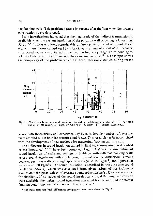
Variations between sound insulation studied in the laboratory and in situ: x--par t i t ion wall m < 150 kg/mZ. C--par t i t ion wall m > 150 kg/m2. [--]--general experience.
years, both theoretically and experimentally by considerable numbers of measure- ments carried out in both laboratories and hi situ. This research has been combined with the development of new methods for measuring flanking transmission.
The differences in sound insulation caused by flanking transmission, as described in the literature, 4's-2° have been compiled. Figure I shows the diminutiort of sound insulation of walls and ceilings in buildings with different flanking walls versus sound insulation without flanking transmission. A distinction is made between partition walls with high specific mass (m < 150 kg/m 2) and lightweight walls (m < 150 kg/m2). The sound insulation is described by the air-borne sound insulation index In, which was calculated from given values of the Luftschall- schutzmass; the given values of average sound reduction index Rwere taken as la for simplicity. If no values of the sotmd insulation without flanking transmission were available, the highest sound insulation measured for the wall under different flanking conditions was takert as the reference value.*
* For these cases the 'real' differences are greater than those shown in Fig. 1.
DIFFERENCES BETWEEN ACOUSTICAL INSULATION PROPERTIES 25
Obviously the differences are considerable and rise with. increasing sound insula- tion. They are also greater for lightweight than for heavyweight constructions.
The present state of knowledge with regard to sound transmission via flanking walls, based on numerous investigations, is as follows:
The sound reduction index of a wall or ceiling is defined by eqns. (i) or (2). The sound level difference between two rooms of a building separated by a wall with sound reduction index R is, however, not given by Lt - L2 = R - 10 log S / A ; in most cases the sound level, L., in the receiving room is increased by energy
,i i l l I
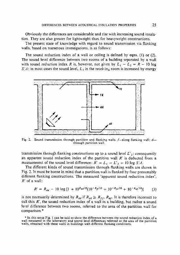
Fig. 2. Sound transmission through partition and flanking walls, f--along flanking wall; d-- through partition wall.
transmission through flanking constructions up to a sound level L'2: consequently an apparent sotmd reduction index of the partition wall R' is deducted from a measurement of the sound level difference: R' = L~ - L'_, + 10 log S~A.
The different kinds of sound transmission through flanking walls are shown in Fig. 2. It must be borne in mind that a partition wall is flanked by four presumably different flanking constructions. The measured 'apparent sound reduction index', R' of a wall:
R' = Ran - 10 log [I + lORaa/l°(lO-R.O ":l° + 10-Rill/t° + lO-Raf:to)] (3)
is not necessarily determined by Ran if Rad ~ Rf.f, Ra$. It is therefore incorrect to call this R', the sound reduction index of a wall in a building, but rather a sound level difference between two rooms, referred to the area of the partition wall for comparison.*
* In this sense Fig. 1 can be said to show the difference between the sound reduction index of a wall measured in the laboratory and sound level differences referred to the area of the partition walls, obtained with these walls in buildings with different flanking conditions.
26 JUDITH LANG
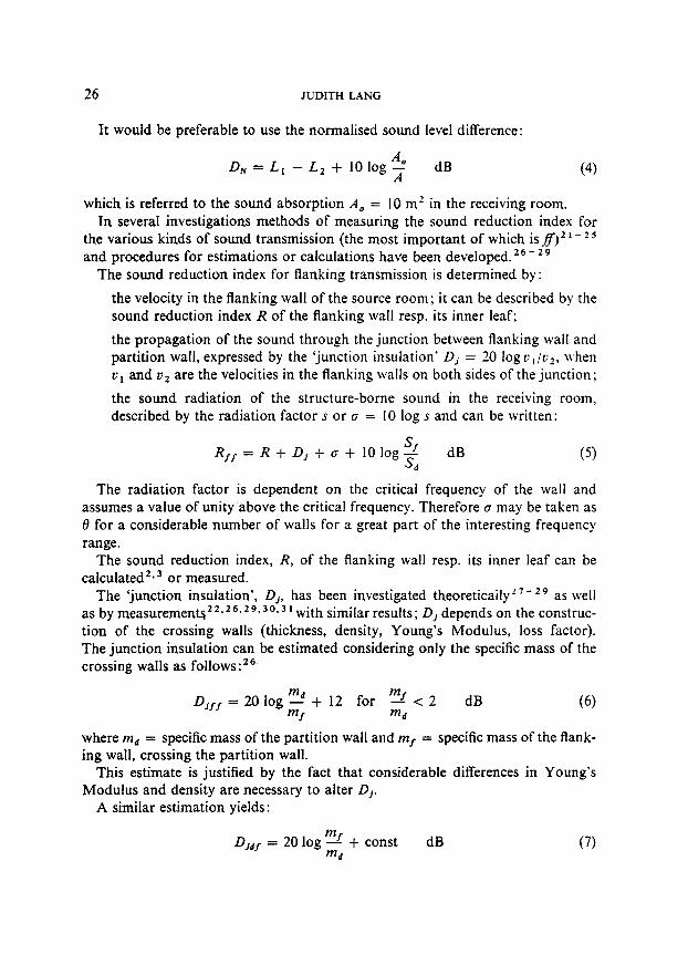
It would be preferable to use the normalised sotmd level difference:
Ds = Lt - L2 + 10 log Ao_ dB (4) A
which is referred to the sound absorption Ao = 10 m 2 in the receiving room. In several investigations methods of measuring the sound reduction index for
the various kinds of sound transmission (the most important of which is f f ) 2 t - 2 5 and procedures for estimations or calculations have been developed. 2 6- 2 9
The sound reduction index for flanking transmission is determined by:
the velocity in the flanking wall of the source room; it cart be described by the sound reduction index R of the flanking wall resp. its inner leaf;
the propagation of the sound through the junction between flanking wall and partition wall, expressed by the 'junction insulation' Dj = 20 log v~/v2, when vt and v 2 are the velocities in the flanking walls on both sides of the junction;
the sound radiation of the structure-borne sound in the receiving room, described by the radiation factor s or a = 10 log s and can be written:
Sf dB (5) R f f = R + Dj + a + 1 0 1 o g ~
The radiation factor is dependent on the critical frequency of the wall and assumes a value of unity above the critical frequency. Therefore a may be taken as 0 for a considerable number of walls for a great part of the interesting frequency range.
The sound reduction index, R, of the flanking wall resp. its inner leaf can be calculated 2. 3 or measured.
The 'junction insulation', D j, has been investigated theoretically z7-29 as well as by measurement~ 2 ~. 26.29.3 o. a, with similar results; Dj depends on the construc- tion of the crossing walls (thickness, density, Young's Modulus, loss factor). The junction insulation can be estimated considering only the specific mass of the crossing walls as follows :26
Djff 20 log mj mf = - - + 12 for - - < 2 dB (6) m s md
where md = specific mass of the partition wall and mf = specific mass of the flank- ing wall, crossing the partition wall.
This estimate is justified by the fact that considerable differences in Young's Modulus and density are necessary to alter Dj.
A similar estimation yields:
Djd f 20 log mf = - - + const dB (7) md
DIFFERENCES BETWEEN ACOUSTICAL INSULATION PROPERTIES 27
The comparison of measured and calculated values shows that the constant is between 5 and 10 dB.
With the calculated values for the sound reduction index and the junction insula- tion the sound reduction index for flanking transmission RIs and Rj.j may be calculated and compared with the sound reduction index of the partition wall.
70
60 -" j ,,..,:..>'-
2..4..7,.
4o ,, , .... , I
30 ~ d- " " " /
20 10 20 30 40 50 I00 200 400 1000
m d kg/m 2
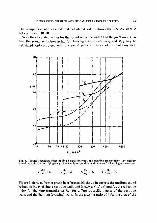
Fig. 3. Sound reduction index of single partition walls and flanking transmission: d=medium sound reduction index of single wall. f = medium sound reduction index for flanking transmission.
md md tad md f l ~ f = 1, f2--~f =2 , f 4 ~ f = 4 , f , 0 ~ 7 = 1 0
Figure 3, derived from a graph in reference 26, shows in curve d the medium sound reduction index of single partition walls and in curvesf~, f2,f4 andfl o the reduction index for flanking transmission Rj.j, for different specific masses of the partition walls and the flanking (crossing) walls. In the graph a ratio of 4 for the area of the
28 JUDITH LANG
flanking structures and the area of the partition wall is considered by a reduction of 6 dB of RIr; this ratio is an average between ceilings (.with 5 riB) and walls (with 7 dB) for areas of ceilings and partition walls common in residential buildings (this value is also used in O NO R M B 8115, "Hochbau, SchaUschutz und H~irsamkeit'.)
It can be seen that for walls with m > 100 kg/m 2 the sound transmission via flanking walls may be only a little lower, or of the same order as, for the partition wall itself, especially if the ratio maim I is approximately 1 to 2. This crude compari- son shows that in the interesting range of walls with m = 300 to 500 kg/m 2 the sound insulation index of a single wall may be reduced by 3 dB. When considering the additional sound transmission given by Rs. a resp. Ra~, the reduction of the insulation can be approximated to 6 dB. This approximation only considers flanking transmission by crossing walls; however, in practice there are also nanking external walls for which Sj is smaller; this means a further reduction of the sound insulation.
These approximate values correspond with measured results. Measurements comparing the sound insulation of concrete floors in the laboratory and in situ showed a diminution of 5 to 7 dB, depending on the number of flanking lightweight walls (thickness < 10 cm). The reduction became still larger when the floors were separated by an air gap. 1 v
Measurements in newly built blocks of dwellings of various traditional and prefabricated construction showed that 50 ~ of the sound energy is transmitted '~y flanking walls, when the partition walls have a sound insulation corresponding, o the standards. 32 This means that higher sound insulation of partition walls and floors than that usually specified in the various international standards is impossible without also considering flanking transmission. Experiments exploring the possibi- lities of high sound insulation proved that reduction of flanking transmission, e.g. by limp panels, is essential. 1 *' * 2
Figure 3 shows the sound reduction index of single partition walls. Double walls have smaller specific mass for a certain sound reduction index and the sound transmission via flanking walls is substantially higher. Figure 3 shows that low values of RIz are obtained with a small specific mass of the partition wall and of the flanking walls; in particular, the specific mass range between 50 and 200 kg/m / is unfavourable, a fact which is also apparent from Fig. 1 for lightweight walls.
The sound transmission may be influenced particularly unfavourably by resonance effects in the flanking structures, e.g. through resilient linings on the walls, which form a mass/spring system made up by the layer of plaster on the resilient layer (like wooden wool slabs, polystyrol and materials with similar stiffness). ~' 33 In addition, resonance effects in certain ceilings with unfavourable cavities can ea.*se a high flanking transmission, reducing the sound insulation by 5 to 10 dB.13'3~
The influence of edge conditions and flanking transmission on the sound insulation between two rooms separated by a partion wall or ceiling raises the questions:
and
DIFFERENCES BETWEEN ACOUSTICAL INSULATION PROPERTIES 29
how to measure the sound insulation of a wall in a laboratory and to derive an estimate ofthe sound insulation in a building under varying conditions
how to define the sound insulation in regulations and recommendations.
LABORATORY MEASUREMENTS
The precise definition of the measuring conditions in laboratories is necessary in order to ensure reliable, reproducible and uniform results on sound insulations. The specification should include: the size of the wall or ceiling; the construction of the flanking walls and the flanking transmission. The size of the wall or ceiling should be of the order of 12 (as in practice). The construction of the flanking wails can be described by the value of the absorption coefficient for bending waves or by the value:
E212k2 + E313k 3 q = Elk (8)
which will be of the order of 0"5 to 2 for most of the test walls. 2 Here E1 represents the bending rigidity and k the bending wave number; the indices 2 and 3 refer to the flanking wall in the source room and the receiving room and the absence of an index denotes the test wall.
In the given range of q the Sound insulation is only slightly influenced by the absorption coefficient for bending waves.
Measurements without energy losses are unsuitable because sound insulations measured in the laboratory would be too low.
Flanking transmission should be avoided; this would be the best way of ensuring uniform results in different laboratories and would also provide a basis for calcula- ting the sound insulation in a building under given flanking conditions. The sound transmission viaffcan be interrupted by an air gap as is used in many laboratories (in this case E313k 3 = 0). More difficulties arise from the insulation of df or fd , i.e. additional insulating limp panels must be mounted to the flanking wall of that room in which the test wall is connected to the flanking wall without air gap.
The avoidance of flanking transmission is the best possible way of achieving sound insulation in practice. The certificate describing the test wall should state not only the sound insulation without flanking transmission, but also sound insulation estimated for the various flanking conditions likely to be encountered in practice, e.g. by approximating the junction insulation in connection with walls of different mass. At present it seems impossible to correctly calculate sound insula- tion in a particular building.
Measurement without flanking transmission is 'advantageous for single walls and also for double walls consisting of flexible leaves such as wooden wool slabs,
30 JUDITH LANG
gypsum boards, etc., which are mostly connected by studs'; there the sound insulation is limited by the connection between the slabs by the studs.
It is more difficult to find the correct measurement for a double wall of two rigid leaves or a rigid wall with a limp panel. These walls give high sound insulations if they are built without connection--something that cannot be obtained in practice (the difference can be 20 dB). 3,
It is recommended that two measurements be made, one with the two leaves of the double wall at both sides of the air gap of the flanking wall and the other with both leaves in connection with the same wall on one side of the air gap (covered with limp panels). At this second measurement one of the two leaves could be insulated from the flanking wall by an insulation board, as is usual in practice. Nevertheless, this is not always of advantage for sound insulation, as has been shown by measurements on double wails of lightweight concrete. 35
Measurement with Bauiibliche Nebenwege (usual flanking transmission)does not seem to be advantageous with regard to the present transition from traditional buildings with heavy walls to lightweight buildings with curtain walls, etc. 'Bauiibliche Nebenwege' can hardly be defined and, in addition, represents only one of a number of possible flanking conditions.
On the other hand, the sound insulation of constructions may be high when the flanking transmission is extremely small, e.g. a ceiling without floating floor, but with a lining underneath, showed an air-borne sound insulation 1, = 65 d B 36 in a building with lightweight partition walls which did not reach the ceiling.
With regard to the short time available for drying walls to be investigated in test rooms, measurements may be mentioned which showed that humidity up to 20~o of weight did not noticeably influence the sound insulation. With higher humidity the sound insulation increases. 37
MEASUREMENTS IN BUILDINGS
Sound insulation in buildings is measured mainly to determine the insulation between two rooms separated by a wall or ceiling but not the insulation of a wall or ceiling separately, i.e. the quantit~y sought is the sound transmission through all ways. If the insulation proves insufficient, the cause has to be analysed. Then it is important to know what amount of sound is transmitted by a single cortstructional element. It is possible to measure the velocity of any wall in the receiving room, to calculate the radiated power and to compare it with the measured air-borne sound level Such measurements in a residential building with insufficient sound insulation between two superposed rooms showed that the sound power radiated from the ceilirtg was very slight compared with that radiated from the flanking walls, particularly from an outer wall with a resilient layer with plaster and from a light- weight partition wall.
DIFFERENCES BETWEEN ACOUSTICAL INSULATION PROPERTIES 31
It is also possible to measure the normalised sound level difference D# t- 3 between two rooms separated by one intermediate room; this characterises the flanking transmission and shows how much the flanking transmission contributes to the sound transmission between two adjacent rooms. Lightweight double leaf walls showed an average sound reduction index of 38 dB in a building while 49 dB had been measured in the laboratory; by measuring the normalised sound level difference D~ t. 3 = 51 dB it was proved that the low sound insulation was not caused by a high flanking transmission. Further measurements showed that the low sound insulation was caused by a rigid fastening of the two leaves instead of an acoustically advantageous fastening which had been used in the test wall in the laboratory.
Measurements between two rooms separated by art intermediate one permit the determination of the flanking transmission, reduced by a further 'junction insula- tion'. This reduction cart be estimated by measuring the normalised sound level difference D~t.** between two rooms separated by two intermediate rooms, which is again higher by one further junctiort insulatiort.
The measurement of velocity of the walls in the receiving room has the advantage of showing which wall radiates most sound and has to be improved. By calculating the radiated sound of walls and ceilings and comparing it with the air-borne sound level in the receiving room, the sound transmission caused by lack of air- tightness, installations, windows artd doors cart be determined.
A disadvantage arises when measurements are carried out between two quite equal rooms with the same normal modes in buildings. 3 s This is especially impor- tant for low frequencies in small rooms. Less sound insulation is measured than, in reality, is given for furnished rooms. It is therefore recommended that diffusers be used in small, empty, identical rooms. Temperatures in source and receiving rooms also influence the results of sound insulation measurements since the normal modes are then moved. Between empty 10 ft cubes, differences in low frequency insulation of 12 dB for 10-'C and 7 dB for 5°C have been measured. 39
SOUND INSULATION 1N BUILDING REGULATIONS
In building regulations the sound insulation between two adjacent rooms should be specified, e.g. by a minimum normalised sound level difference (as is done, for instance, in Denmark, Norway and Sweden). It is less advantageous to specify the sound reduction index of the wall or ceiling since constructions which prove a sufficient sound reduction index in the laboratory may not ensure sufficient sound insulation between the rooms of an actual building. The architect of every building should have to estimate the attainable sound level difference between two rooms by using a partition wall or ceiling and flanking walls with given sound reduction
* The indices denote the r o o m s between which the sound level difference is measured , beginning with I in the source room.
32 JUDITH LANG
indices and junction insulation. Architects would be able to do this for a consider- able number of buildings if the certificates concerned with the sound reduction index measured in laboratories contained proper estimates of junction insulation and flanking transmission. The size of the wall does not much influence the normalised sound level difference in residential buildings (Ao = 10 m 2, S ~ 10 m2), but is important for buildings with larger wall-areas.
In the Austrian standard, ONORM B 8115 'Hochbau, Schallschutz und Hiirsam- keit' the sound reduction index for partition walls, ceilings, outer walls, etc., is specified in addition to the junction insulation in the flanking walls crossing the partition walls and ceilings. Therefore for partition walls between two rooms in the same flat it is required that 1o = 44 dB and for partition walls and ceilings between two flats 1 a = 52 dB; further, the junction insulation in partition walls between two rooms in the same fiat, crossing walls or ceilings between two flats, has to be Dj = 14 dB and for outer walls 1o = 52 dB and Dj = 6 dB. The value of Dj is derived from the previously mentioned relation between sound reduction index for flanking transmission, sound reduction index of the flanking wall and junction insulation, considering the ratio SflSa = 4. By means of these specifications the sound insulation between two rooms is ensured; they also require that the architect has to estimate the junction insulation in the flanking walls. Examples of how the requirements may be fulfilled are given in the standard.
SOUND TRANSMISSION THROUGH WINDOWS, DOORS AND STAIRCASES
Sound transmission through open windows in two adjacent or superposed rooms, doors and staircases has been investigated only perfunctorily. The measuring locations in buildings are usually selected in such a way that sound transmission through windows and doors is as low as possible. Measurements showed, how- ever, that a sound transmission may occur, for example, between two flats through doors separating the flats from the staircases; this is especially important if the living-rooms are adjacent to the doors. The sound insulation given by the partition walls is reduced at high frequencies if the air-tightness of the doors is inadequate. ~ 7
Experiments in a test building with a sound-absorbing staircase showed that the sound insulation between two superposed rooms is naturally very much reduced when both doors are open (Io = 30 dB, referred to the area of the ceiling) ; with one door closed the sound insulation is increased to Io = 51 dB and with both doors (single doors) closed to Io = 62 dB. If there are closed double doors involved the sound insulation is increased further to Io -- 63 dB. 11 The results are essentially determined by the high sound absorption in the staircase.
In the same test building measurements on sound transmission through the air via open and closed windows were carried out. With windows in two superposed rooms open I° = 42 dB, with one single window closed Ia = 58 dB, with two single
DIFFERENCES BETWEEN ACOUSTICAL INSULATION PROPERTIES 33
windows closed I, = 61 dB and with two double windows closed Ia = 63 dB were recorded. Obviously normal sound insulation, as used at present in residential buildings, is not reduced if even only one single window is closed.
SOUND TRANSMISSION BY INSTALLATIONS
Sound transmission by various installations (air, water, heating) is a serious cause of diminution of sound insulation given by walls and floors. This diminution can be high.
Air ducts and dust-collector shafts An important sound transmission is given by air ducts which connect different
rooms, for example, ducts from heating and air conditioning plants. Measurements showed that the sound insulation cart be reduced by I0 dB if one duct is connected to different rooms. ~7'4° In numerous investigations, however, solutions were found to ensure sufficient sound insulation in air shafts by sound absorption of the inner surface of the shaft or by silencers or appropriate constructions of air inlet and outlet. 4 ~.42 When designing the necessary sound absorption or sound insula- tion the sound insulation given by the air duct has to be at least 3 dB higher than that of the respective wall or ceiling, to ensure that the given sound insulation is not reduced.
In the same way as air ducts, dust-collector shafts may also reduce sound insula- tion if they are connected to the kitchens of different flats. ~ 7 This diminution of sound insulation can be avoided by locating the dust-collector shaft outside the flats (in the staircase).
Water-filled pipes Water-filled pipes (of a water installation or warm water heating installation)
which break through a wall or ceiling may also reduce sound insulation. The essential causes are breaks and sound bridges arising in double leaf constructions or floating floors.
For example, a heating pipe breaking through the ceiling reduced the sound insulation between two superposed rooms from 1, --- 51 dB to Io = 48 dB, as shown by experiments with lined heating pipes and radiators.
As shown by various experiments, 43 the sound insulation of a small slit is important for total sound insulation. Practical methods of insulating pipes passing through walls have been developed, a4 The problem is simpler if the pipes are located in the walls as is usual in Austria, but even in this case sound transmission via the water-filled pipes connecting radiators in different rooms is noticeable.
An investigation on the sound insulation of a 14 em hollow brick wall plastered on both sides, located in a test room, showed the following results. 45 The fastening
34 JUDITH LANG
of one radiator (without water) to one or both sides of the wall has no influence on the sound insulation of that wall. The fastening of radiators (without water) to both sides of the wall which are connected with an ½ in iron pipe, covered in the wall by a PVC pipe of 15 cm length, causes a reduction of the sound insulation by 3 to 10 dB for frequencies above 1000 Hz, the reduction depending on the design of the radiators. This reduction is mainly compensated for if the radiators are filled with water when only a small reduction above 2500 Hz remains. If the iron pipe is omitted and the radiators are connected to the PVC pipe the result is the same. I f the soft PVC layer between pipe and wall is replaced by a rigid fixture, the sound insulation is also reduced by water-filled radiators; the reduction increasing up to 10 dB above 1000 Hz, depending on the radiator's design.
Measurements in buildings showed 46 that the sound insulation between super- posed rooms is essentially reduced by 10 to 15 dB for frequencies above 630 Hz by radiators and their connections. Even the sound insulation between two rooms separated by an intermediate room was reduced by 5 to 10 dB for frequencies above 800 Hz by the radiators. The normalised sound level difference between two superposed rooms, determined by the sound transmission caused by radiators alone, was 45 to 65 dB according to the design of the radiator in question, indepen- dent of frequencies, with an average value of about 50 dB; if measured between two rooms separated by an intermediate one it was 60 to 65 dB.
Obviously the design of the radiators greatly influences the sound insulation and should be considered carefully, especially when higher sound insulation is required. An appropriate measuring method for the sound insulation of radiators should be developed.
SOUND INSULATION AND WORKMANSHIP
Differences in sound insulation caused by different workmanship also occur. It is not possible to give average values for these differences or to calculate them. The difference may be negligible or as high as 10 or 20 dB. In the latter case the usual cause is a lack of air-tightness or sound bridges in double leaf constructions. In general it may be said that the differences grow with the probability of faults increasing according to the complexity of the construction. A simple brick wall or concrete floor may show no difference, a transportable light wall construction or a double leaf wall with a particular manner of fastening the boards to the double studs, or tightening the joints, may, however, show a high sound insulation in the laboratory where the engineer and craftsman attempt to achieve a high quality certificate, but the sound insulation is reduced when, in practice, hundreds of walls have to be erected in a short time by unskilled workmen.
Insufficient sound insulation in buildings is very often caused by the ignorance of workmen with regard to the importance of minute details of sound insulation.

DIFFERENCES BET-WEEN ACOUSTICAL INSULATION PROPERTIES 35
Often design details of an element are varied, a fact which the layman may consider unimportant but which makes work simpler and the element cheaper. For example, in the laboratory a double leaf wall with high sound insulation was developed for partition walls in a university; I, was 49 dB. These walls were used in the whole building. The sound insulation, measured after installation, was I, = 38 dB; further measurements showed that flanking transmission had no influence, but the resonance frequency of the double leaf wall was substantially higher than for the prototype in the laboratory because the studs had been slightly varied. In another block of the same university another system of double leaf walls was selected. The sound insulation in the building was, in this case, exactly the same as that measured in the laboratory.
These differences in sound insulation in laboratory and field due to workmanship could be avoided by training engineers and craftsmen in acoustics. It would be useful, too, to describe in a sound insulation certificate the importance of critical details for sound insulation.
CONCLUSIONS
The preceding is a summary of some of our measurements and of a survey of the literature available in our Institute and, particularly, of literature and remarks received from colleagues, for which I wish to express my appreciation.
The state of knowledge of the differences between sound insulation measured in the laboratory and in the field is based on a considerable number of results and the causes are manifold. There is, however, r, ot much information available on methods of calculating sound insulation in buildings. Further measurements, based on well-defined methods, could be useful. It also seems necessary to inform everyone working on the construction of buildings about the various details which may influence sound insulation.
REFERENCES
1. ISO Recommendation RI40, Field and Laboratory Measurements of Airborne and Impact Sound Transmission, 1st Edition (January, 1960).
2. M. HECKL; Die Schalld~mmung yon homogenen Einfachw~nden endlicher Fliche, Acustica, 10 (1960) 2.
3. K. GOSELE, Zur Luftschalldimmung von einschaligen Winden und Decken. Aeustica, 20 (1968) 6.
4. C.O. JORGEN, Sound insulation in laboratory and in buildings, Norges Byggforskningsinstitutt, Saertrykk, 158 (1968).
5. J. E. R. CONSTABLE, The transmission of sound in a building by indirect paths, Proc. Phys. Soc., London, 50 (1938).
6. G. H. AsroN, Report of the 1948 Summer Symposium of the Acoustic Group, Phys. Sot., (1949).
36 JUDITH LANG
7. P. H. PARKIN and H. R. HUMPHREYS, Measurements and sound insulation in houses and flats, 7. Roy. Inst. Brit. Archit., 57 (1950) p. 10.
8. H. J. PURKtS and P. H. PARKIN, Indirect sound transmission with joist and solid floors, Acustiea, 2 (1952).
9. A. EtSENaERO, Untersuchungen fiber die Schalldiimmung zwiscben benachbarten Raumen mit durehlanfendem schwimmenden Estrich, Wdrme Kdlte Schall, 1 l.Jhg. (1966), H.2.
10. A. EtSENS~aG, Ober den Einfluss leichter Zwischanwande auf die Schalldimmung in Wohn- bauten. Schallschutz yon Bauteilen, Verlag Wilhelm Ernst u~ Sohn, Berlin (1960).
11. A. EISENBERO, Versuche zur Erzielung eines erh6hten Schallschutzes bei f~bereinanderliegender RAumen, Bericht Nr. 25-8/69 des Staatl. Materialprfifungsamtes Nordrbein-Westfalen, Dortmund.
12. P. DAMMIG arid G. VENZKE, Improvement of sound insulation between two adjacent rooms by progressive reduction of direct and flanking transmission, lEE Conference, Publication No. 26 (Acoustics, noise and its control), London, 1967.
13. K. GOSELE, Erh6hung der SchalI-Langsleitung dutch bestimmte Hohlk6rperdecken. Luft- schall, Trittschall, K6rpcrschall, Verlag Wilhelm Ernst u. Sohn, Berlin, 1964.
14. K. GOSELE, Versehlechterung der Schalld/tmmung von Decken und W~inden durch anbetonierte W~.rmediimmplatten, Ges. lng., 82: Jhg. (1961), H.1 I.
15. TH. Klus'rEN and H. W. MULLER, Uber den Einfluss der Nebenwegfibertragung auf die Schall- d ~ m u n g yon Trennwandkonstruktionen. Die Schalltechnik, 16. Jhg. (1956), H.18.
16. F. BRUCKM^YER, Hellh6rigkeit (Sc.hall/ingsleitung)yon Bauten einschliesslich Installations- geriiuschen, Wohnbauforsehung in ~sterreich, Jhg. 9 (1964), Folge 3/4.
17. R. Jesse and R. PLAGNOL, Les diff6rences entre les isolements acoustiques r~els et les mesures de laboratoire, Cahiers du CSTB No. 86, Cahier, 748 (1967).
18. O. BRANDT, En unders6kning av flanktransmission i l/ittelement, Stockholm (1961). 19. T. KtHLMANN, Rumsisolering mot luftljud i bostadshus. Inverkan av flanktransmission och
kantanslutninger, Byggmdstaren (1963) No. 5. 20. A. LAUBER, Pers6nliche Mitteilung. 21. E. MEYER, P. H. PARKIN, H. OBERST and H. J. PURKIS, A tentative method for the measurement
of indirect sound transmission in buildings, Acustica, 1 (1951). 22. K. GOSELE, Der Einfluss der Hauskonstruktion auf die Schall-Liingsleitung bei Bauten, Ges.
Ing., 75. Jhg. (1954), H.17/18. 23. J. VAN DEN EIJK and M, L. KASTELEYN, A method of measuring flanking transmission in
flats, Aeustiea, 5 (1955) 5. 24. W. ERLEa, Die Bestimmung der Nebenwege bei Luftschall nach der Methode der K6rper-
schallmessung und K6rperschallerregung, Hoehfrequenzteehnik und Elektroakustik (1959), H.4/5.
25. W. FASOLD and G. MERKEL, Entwicklung und Aufbau einer Messapparatur zur Durchfiihrung yon Flankenwegmessungen nach Erler, Hochfrequenztechnik und Elektroakustik (1962), H.3.
26. K. GOSEL~, Untersuchungen zur SchalI-Liingsleitung in Bauten. Schallschutz in GebS.uden, Verlag Wilhelm Ernst u. Sohn, Berlin, 1968.
27. L. CREMER, Propagation of structure-borne sound, Dept. of Scientific and Industrial Research. Report No. 1 (series B), HMSO 1952.
28. L. CREMER and M. HECKL, K6rperschall. Springer-Verlag, Berlin 1967. 29. T. KIHLMANN, Transmission of structure-borne sound in buildings, National Swedish Institute
for Building Research, Report 9/1967. 30. R. MARTIN and H. W. MULLER, Ober K6rperschalluntersuchungen in Wohnbauten, Acustica,
Akust. Beihefte H.I (1956). 31. W. WES'rPHAL, Ausbreitung yon K6rperschall in Gebiiuden, Acustica, Akust. Beihefte H.1
(1957). 32. W. FASOLD and G. MERKEL, Der Einfluss der FlankenwegObertragung aufdie Luftschalld~im-
mung yon Wohnungstrennw~inden und -decken. Schriftenreihen der Bauforschung, Reihe Technik und Organisation, 11.24 (1969).
33. R. F. HIGGINSON, Sound insulation between rooms having resilient linings on the walls, Building Research Station, August 1969, En 63/69.
34. R. JessE, Les patois doubles utilis6es :~ des fins acoustiques. Cahiers du CSTB No. 80, Cahier, 693 (1966).
35. A. EISENBERG, Schalld/immung von Doppelw/inden aus Leichtbeton, Schallsehutz von Bauteilen, Verlag Willhelm Ernst u. Sohn (1960).
36. K. GOSELE, Zum Schallschutz im Bauwesen, Ges. lng., 88. Jhg. (1967), H.3. 37. TrL KRIS'rEN, H. SCHULZE and R. PALAZY, Abhingigkeit des Schallschutzes veto Feuchtig-
keitsgehalt der Bauteile. Schallschutz yon Bauteilen, Verlag Wilhelm Ernst u. Sohn (1960).
DIFFERENCES BETWEEN ACOUSTICAL INSULATION PROPERTIES 37
38. M. HECKL and K. SEIFERT, Untersuchungen fiber den Einfiuss der Eigen-resonanzen der Messrium© auf die Ergebnisse von Schalldimmessungen, Acustica, 3 No. 4 (1958).
39. W. E. SCHOLES, A note on the repeatability of field measurements of airborne sound insulation, J. Sound Vibr., 10(1) (1969).
40. J. LANG, Schallschutztechnisehe Gesichtspunkte zum Bau yon Klimaanlagen, Jahresbericht 1961/62 des Technologischen Gewerbemuseums, Wien.
41. R. Josst, Transmission du son par les conduits de ventilation, Cahiers du C S T 8 No. 70, Cahier 590 (1964).
42. L. CREMER and M. HtCKL, Luftschallfibertragung fiber L~ftungs- und Abgaskan~i.le. Sehall- schutz yon Bauteilen, I/erlag Wilhelm Ernst u. Sohn (1960).
43. M. C. GOMPER'PS, The 'sound insulation' of circular and slit-shaped apertures, Acustica, 14 No. 1 (1964).
44. K. HEMPEL, Akustische Untersuchungen an Rohrschellen und Rohrdurchffihrungen. Schrif- tenreihen der Bauforschung, Reihe Technik und Organisation, H.24 (1969).
45. D~termination exl~rimentale de crit~res fonctionnels d'isolation et d'~tanch~it~ pour parois et cloisons des bgttiments. Centre Scientifique et Technique de la Construction, Bruxelles. D.340.42 (1968).
46. P. O. RENHAI.L, LjudSverf6ring via radiatorer. VVS, 3 (1967).