Embed Size (px)
Citation preview
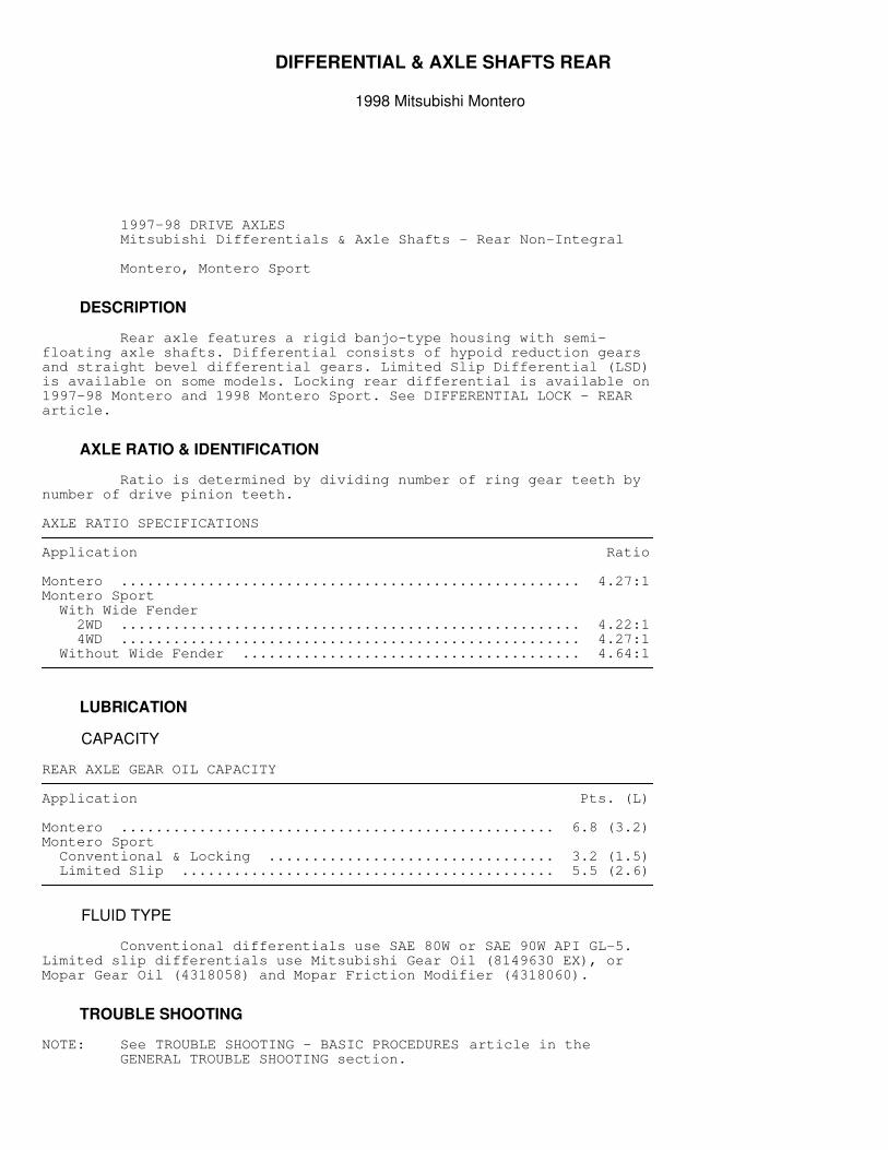
DIFFERENTIAL & AXLE SHAFTS REAR
1998 Mitsubishi Montero
1997-98 DRIVE AXLES Mitsubishi Differentials & Axle Shafts - Rear Non-Integral
Montero, Montero Sport
DESCRIPTION
Rear axle features a rigid banjo-type housing with semi-floating axle shafts. Differential consists of hypoid reduction gearsand straight bevel differential gears. Limited Slip Differential (LSD)is available on some models. Locking rear differential is available on1997-98 Montero and 1998 Montero Sport. See DIFFERENTIAL LOCK - REARarticle.
AXLE RATIO & IDENTIFICATION
Ratio is determined by dividing number of ring gear teeth bynumber of drive pinion teeth.
AXLE RATIO SPECIFICATIONS�������������������������������������������������������������������������������������������������������������������������������������������
Application Ratio
Montero ..................................................... 4.27:1Montero Sport With Wide Fender 2WD ..................................................... 4.22:1 4WD ..................................................... 4.27:1 Without Wide Fender ....................................... 4.64:1�������������������������������������������������������������������������������������������������������������������������������������������
LUBRICATION
CAPACITY
REAR AXLE GEAR OIL CAPACITY�������������������������������������������������������������������������������������������������������������������������������������������
Application Pts. (L)
Montero .................................................. 6.8 (3.2)Montero Sport Conventional & Locking ................................. 3.2 (1.5) Limited Slip ........................................... 5.5 (2.6)�������������������������������������������������������������������������������������������������������������������������������������������
FLUID TYPE
Conventional differentials use SAE 80W or SAE 90W API GL-5.Limited slip differentials use Mitsubishi Gear Oil (8149630 EX), orMopar Gear Oil (4318058) and Mopar Friction Modifier (4318060).
TROUBLE SHOOTING
NOTE: See TROUBLE SHOOTING - BASIC PROCEDURES article in the GENERAL TROUBLE SHOOTING section.
TESTING & INSPECTION
AXLE SHAFT END PLAY
Montero & Montero Sport Using dial indicator, check axle shaft end play. End playshould be .010" (.25 mm). If end play is not within specification,replace axle bearing. See AXLE SHAFT OVERHAUL under OVERHAUL.
AXLE TOTAL BACKLASH
1) Raise and support rear axle. Place transmission inNeutral. Apply parking brake. Rotate drive shaft clockwise. Placereference marks on pinion dust cover and differential housing. 2) Rotate drive shaft counterclockwise, and measure distancebetween reference marks. Differential must be removed and backlashadjusted if distance exceeds 0.2" (5 mm). See RING GEAR BACK-LASHprocedure under DIFFERENTIAL ASSEMBLY (LIMITED SLIP) under OVERHAUL.
LIMITED SLIP DIFFERENTIAL PRELOAD
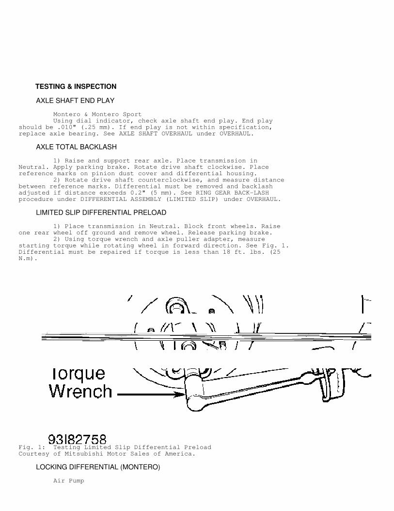
1) Place transmission in Neutral. Block front wheels. Raiseone rear wheel off ground and remove wheel. Release parking brake. 2) Using torque wrench and axle puller adapter, measurestarting torque while rotating wheel in forward direction. See Fig. 1.Differential must be repaired if torque is less than 18 ft. lbs. (25N.m).
Fig. 1: Testing Limited Slip Differential PreloadCourtesy of Mitsubishi Motor Sales of America.
LOCKING DIFFERENTIAL (MONTERO)
Air Pump
Connect air pressure gauge in-line to air hose from air pump.Air pump is located in right storage area, under rear seat. Connectbattery voltage to air pump (positive lead to Red wire). The air pumpis operating correctly when the following sequences occur;
* Pump should operate for no more than 5 seconds. * Pressure should be 4-6 psi (.28-.41 kg/cm
�
) within 10-20 seconds after pump has stopped. * After air pump has stopped operating, it should not restart operating for 5 minutes.
Center Differential Lock Operation Switch See ANTI-LOCK BRAKE SYSTEM article in BRAKES.
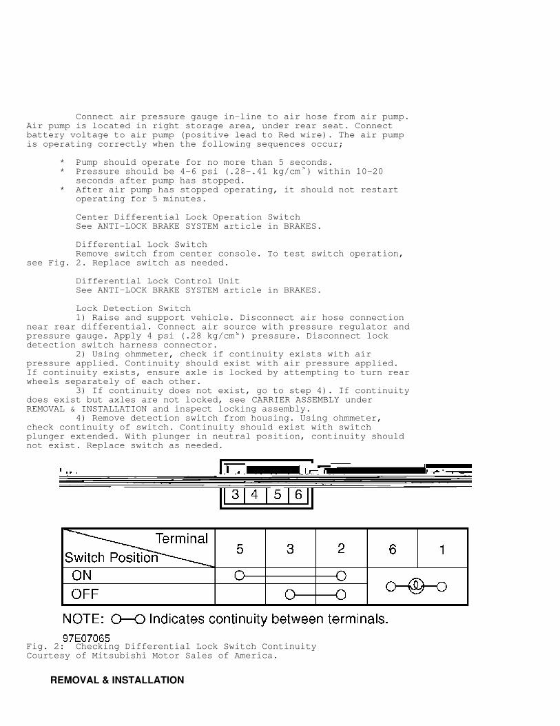
Differential Lock Switch Remove switch from center console. To test switch operation,see Fig. 2. Replace switch as needed.
Differential Lock Control Unit See ANTI-LOCK BRAKE SYSTEM article in BRAKES.
Lock Detection Switch 1) Raise and support vehicle. Disconnect air hose connectionnear rear differential. Connect air source with pressure regulator andpressure gauge. Apply 4 psi (.28 kg/cm
�
) pressure. Disconnect lockdetection switch harness connector. 2) Using ohmmeter, check if continuity exists with airpressure applied. Continuity should exist with air pressure applied.If continuity exists, ensure axle is locked by attempting to turn rearwheels separately of each other. 3) If continuity does not exist, go to step 4). If continuitydoes exist but axles are not locked, see CARRIER ASSEMBLY underREMOVAL & INSTALLATION and inspect locking assembly. 4) Remove detection switch from housing. Using ohmmeter,check continuity of switch. Continuity should exist with switchplunger extended. With plunger in neutral position, continuity shouldnot exist. Replace switch as needed.
Fig. 2: Checking Differential Lock Switch ContinuityCourtesy of Mitsubishi Motor Sales of America.
REMOVAL & INSTALLATION
AXLE SHAFT R & I
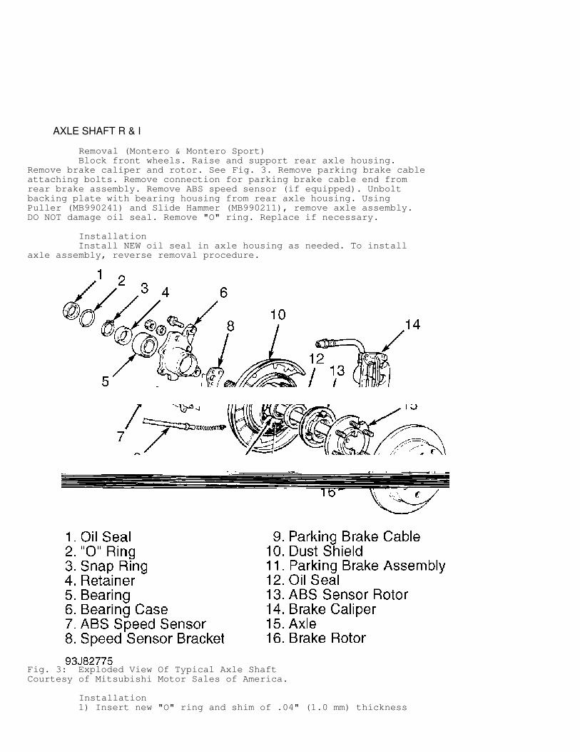
Removal (Montero & Montero Sport) Block front wheels. Raise and support rear axle housing.Remove brake caliper and rotor. See Fig. 3. Remove parking brake cableattaching bolts. Remove connection for parking brake cable end fromrear brake assembly. Remove ABS speed sensor (if equipped). Unboltbacking plate with bearing housing from rear axle housing. UsingPuller (MB990241) and Slide Hammer (MB990211), remove axle assembly.DO NOT damage oil seal. Remove "O" ring. Replace if necessary.
Installation Install NEW oil seal in axle housing as needed. To installaxle assembly, reverse removal procedure.
Fig. 3: Exploded View Of Typical Axle ShaftCourtesy of Mitsubishi Motor Sales of America.
Installation 1) Insert new "O" ring and shim of .04" (1.0 mm) thickness
into left side axle housing. Install left axle shaft assembly intoaxle housing, and tighten nuts to specification. SeeTORQUE SPECIFICATIONS. 2) Install right axle shaft assembly into axle housingwithout shim or "O" ring. Temporarily tighten nuts in diagonalsequence to 51.6 INCH lbs. (5.8 N.m) in 2 stages. Measure clearancebetween bearing case of right axle and rear axle housing end withfeeler gauge. 3) Select shims equal to sum of measured clearance plus .002-.008" (.05-.20 mm). Remove right axle shaft, and install selectedshim(s) and "O" ring into right axle housing end. Install right axleshaft assembly into rear axle housing. Tighten nuts in diagonalsequence to specification. See TORQUE SPECIFICATIONS. 4) Using dial indicator, check end play of axle shaft. Endplay should be .002-.008" (.05-.20 mm). If end play is not withinspecification, change shim(s) to obtain correct end play. Reverseremoval procedure to install remaining components. Adjust parkingbrake, and bleed brake system.
CARRIER ASSEMBLY
Removal Raise and support vehicle. Drain gear oil. Mark drive shaftflange-to-pinion flange position. Remove drive shaft. Remove axleshafts. See AXLE SHAFT R & I. Support differential carrier with jack.Remove differential carrier retaining nuts. Remove differentialcarrier.
Inspection Check for leaks at vent plug, differential carrier companionflange and where carrier joins axle housing.
Installation Apply sealant to axle housing surface. To install, reverseremoval procedure. Align marks on drive shaft and pinion flange.
DRIVE SHAFT
Removal Make match marks on drive shaft yoke flange and pinionflange. Remove bolts and drive shaft from vehicle.
Installation To install, reverse removal procedure. Ensure match marks arealigned. Tighten bolts to specification. See TORQUE SPECIFICATIONS.
OVERHAUL
AXLE SHAFT OVERHAUL
Removal 1) Secure axle shaft assembly in a vise, and remove oneretainer bolt from backing plate. Push bearing case completely to sideof dust cover. Place adhesive tape around edge of bearing case atretainer bolt hole to prevent damage.
CAUTION: DO NOT damage bearing case or axle shaft when grinding or chiseling retainer ring.
2) Secure axle shaft, and grind retainer ring until retainerring wall thickness is .04-.06" (1.0-1.5 mm) on axle shaft side and .08" (2.0 mm) on bearing side. See Fig. 4.
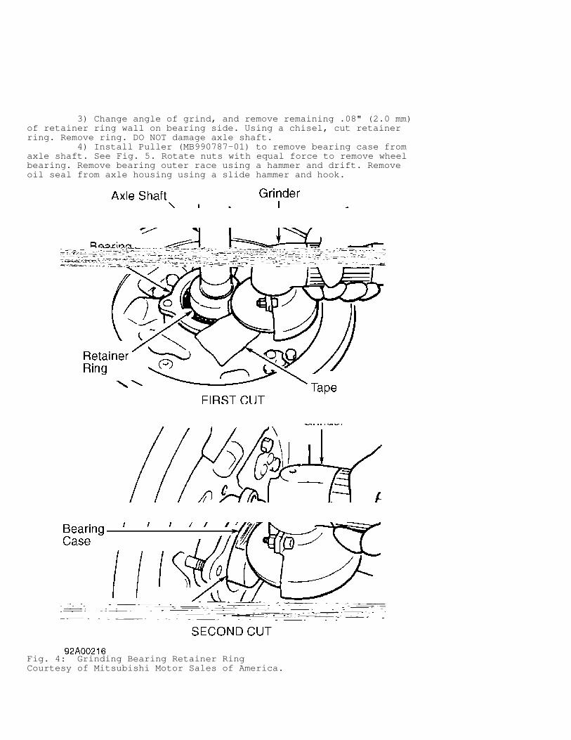
3) Change angle of grind, and remove remaining .08" (2.0 mm)of retainer ring wall on bearing side. Using a chisel, cut retainerring. Remove ring. DO NOT damage axle shaft. 4) Install Puller (MB990787-01) to remove bearing case fromaxle shaft. See Fig. 5. Rotate nuts with equal force to remove wheelbearing. Remove bearing outer race using a hammer and drift. Removeoil seal from axle housing using a slide hammer and hook.
Fig. 4: Grinding Bearing Retainer RingCourtesy of Mitsubishi Motor Sales of America.
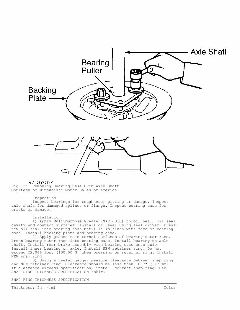
Fig. 5: Removing Bearing Case From Axle ShaftCourtesy of Mitsubishi Motor Sales of America.
Inspection Inspect bearings for roughness, pitting or damage. Inspectaxle shaft for damaged splines or flange. Inspect bearing case forcracks or damage.
Installation 1) Apply Multipurpose Grease (SAE J310) to oil seal, oil sealcavity and contact surfaces. Install oil seal using seal driver. Pressnew oil seal into bearing case until it is flush with face of bearingcase. Install backing plate and bearing case. 2) Apply grease to external surfaces of bearing outer race.Press bearing outer race into bearing case. Install bearing on axleshaft. Install rear brake assembly with bearing case onto axle.Install inner bearing on axle. Install NEW retainer ring. Do notexceed 22,046 lbs. (100,00 N) when pressing on retainer ring. InstallNEW snap ring. 3) Using a feeler gauge, measure clearance between snap ringand NEW retainer ring. Clearance should be less than .007" (.17 mm).If clearance exceeds specification, install correct snap ring. SeeSNAP RING THICKNESS SPECIFICATION table.
SNAP RING THICKNESS SPECIFICATION�������������������������������������������������������������������������������������������������������������������������������������������
Thickness: In. (mm) Color
.060 (1.52) .................................................... Red
.067 (1.70) ................................................. Purple
.073 (1.85) ................................................... Blue
.079 (2.01) ................................................. Yellow
.085 (2.16) ................................................ Neutral�������������������������������������������������������������������������������������������������������������������������������������������
DIFFERENTIAL ASSEMBLY (CONVENTIONAL)
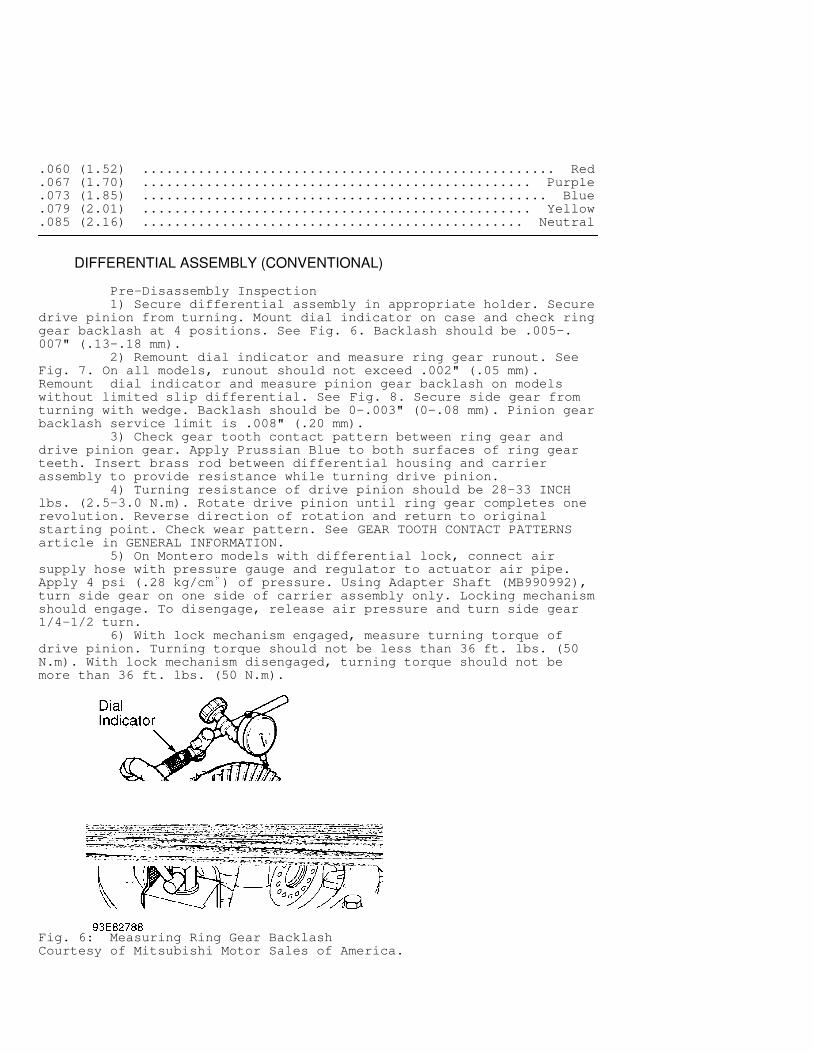
Pre-Disassembly Inspection 1) Secure differential assembly in appropriate holder. Securedrive pinion from turning. Mount dial indicator on case and check ringgear backlash at 4 positions. See Fig. 6. Backlash should be .005-.007" (.13-.18 mm). 2) Remount dial indicator and measure ring gear runout. SeeFig. 7. On all models, runout should not exceed .002" (.05 mm).Remount dial indicator and measure pinion gear backlash on modelswithout limited slip differential. See Fig. 8. Secure side gear fromturning with wedge. Backlash should be 0-.003" (0-.08 mm). Pinion gearbacklash service limit is .008" (.20 mm). 3) Check gear tooth contact pattern between ring gear anddrive pinion gear. Apply Prussian Blue to both surfaces of ring gearteeth. Insert brass rod between differential housing and carrierassembly to provide resistance while turning drive pinion. 4) Turning resistance of drive pinion should be 28-33 INCHlbs. (2.5-3.0 N.m). Rotate drive pinion until ring gear completes onerevolution. Reverse direction of rotation and return to originalstarting point. Check wear pattern. See GEAR TOOTH CONTACT PATTERNSarticle in GENERAL INFORMATION. 5) On Montero models with differential lock, connect airsupply hose with pressure gauge and regulator to actuator air pipe.Apply 4 psi (.28 kg/cm
�
) of pressure. Using Adapter Shaft (MB990992),turn side gear on one side of carrier assembly only. Locking mechanismshould engage. To disengage, release air pressure and turn side gear1/4-1/2 turn. 6) With lock mechanism engaged, measure turning torque ofdrive pinion. Turning torque should not be less than 36 ft. lbs. (50N.m). With lock mechanism disengaged, turning torque should not bemore than 36 ft. lbs. (50 N.m).
Fig. 6: Measuring Ring Gear BacklashCourtesy of Mitsubishi Motor Sales of America.
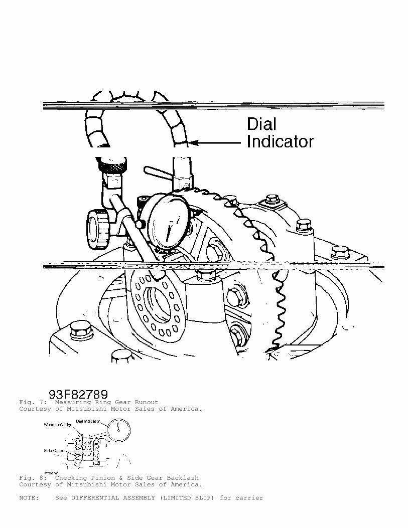
Fig. 7: Measuring Ring Gear RunoutCourtesy of Mitsubishi Motor Sales of America.
Fig. 8: Checking Pinion & Side Gear BacklashCourtesy of Mitsubishi Motor Sales of America.
NOTE: See DIFFERENTIAL ASSEMBLY (LIMITED SLIP) for carrier
assembly and drive pinion installation.
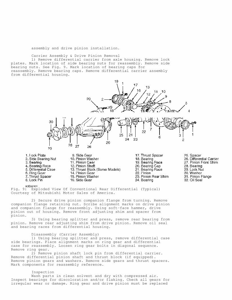
Carrier Assembly & Drive Pinion Removal 1) Remove differential carrier from axle housing. Remove lockplates. Mark location of side bearing nuts for reassembly. Remove sidebearing nuts. See Fig. 9. Mark location of bearing caps forreassembly. Remove bearing caps. Remove differential carrier assemblyfrom differential housing.
Fig. 9: Exploded View Of Conventional Rear Differential (Typical)Courtesy of Mitsubishi Motor Sales of America.
2) Secure drive pinion companion flange from turning. Removecompanion flange retaining nut. Scribe alignment marks on drive pinionand companion flange for reassembly. Using soft-face hammer, drivepinion out of housing. Remove front adjusting shim and spacer frompinion. 3) Using bearing splitter and press, remove rear bearing frompinion. Remove rear adjusting shim from drive pinion. Remove oil sealand bearing races from differential housing.
Disassembly (Carrier Assembly) 1) Using bearing splitter and press, remove differential caseside bearings. Place alignment marks on ring gear and differentialcase for reassembly. Loosen ring gear bolts in diagonal sequence.Remove ring gear. 2) Remove pinion shaft lock pin from differential carrier.Remove differential pinion shaft and thrust block (if equipped).Remove pinion gears and washers. Remove side gears and thrust spacers.Mark components for reassembly reference.
Inspection Wash parts in clean solvent and dry with compressed air.Inspect bearings for discoloration and/or flaking. Check all gears forirregular wear or damage. Ring gear and drive pinion must be replaced
as matched set. Side gears and pinion gears must be replaced asmatched set.
Reassembly & Adjustment 1) Install thrust spacers, side gears, pinion washers andpinion gears in differential case. DO NOT install thrust block (ifequipped) at this time. 2) Install pinion shaft without lock pin. Check pinion andside gear backlash. Install wooden wedge to lock side gears. SeeFig. 8. Using dial indicator, measure gear backlash. Backlash shouldbe .0004-.0030" (.010-.080 mm). Service limit is .008" (.20 mm). 3) Adjust backlash by using different side gear spacers.Ensure both sides are equally shimmed. Install thrust block (ifequipped) once correct backlash is obtained. Install pinion shaft lockpin from ring gear side of carrier housing. Securely stake pin in 2places. Ensure adhesive is removed from ring gear mounting bolts andgear mounting surface. Clean internal threads with tap. 4) Ensure alignment marks on differential case and ring gearalign. Apply Loctite 271 to bolts, and install ring gear ondifferential case. Tighten bolts in diagonal sequence tospecification. See TORQUE SPECIFICATIONS. Using appropriate adapter,press on carrier side bearings.
DIFFERENTIAL ASSEMBLY (LIMITED SLIP)
NOTE: Manufacturer does not provide disassembly or reassembly procedures for locking type differential. Use illustrations for exploded views of assembly. See Figs. 11 and 12.
NOTE: See PRE-DISASSEMBLY INSPECTION under DIFFERENTIAL ASSEMBLY (CONVENTIONAL) before disassembling carrier assembly. For carrier assembly and drive pinion removal, see DIFFERENTIAL ASSEMBLY (CONVENTIONAL).
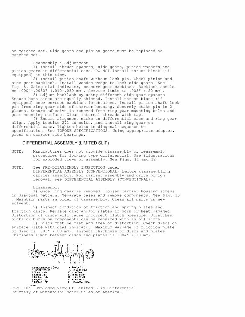
Disassembly 1) Once ring gear is removed, loosen carrier housing screwsin diagonal pattern. Separate cases and remove components. See Fig. 10. Maintain parts in order of disassembly. Clean all parts in newsolvent. 2) Inspect condition of friction and spring plates andfriction discs. Replace disc and/or plates if worn or heat damaged.Distortion of discs will cause incorrect clutch pressure. Scratches,nicks or burrs on components can be repaired with an oil stone. 3) Discs must be flat and free of distortion. Check discs onsurface plate with dial indicator. Maximum warpage of friction plateor disc is .003" (.08 mm). Inspect thickness of discs and plates.Thickness limit between discs and plates is .004" (.10 mm).
Fig. 10: Exploded View Of Limited Slip DifferentialCourtesy of Mitsubishi Motor Sales of America.
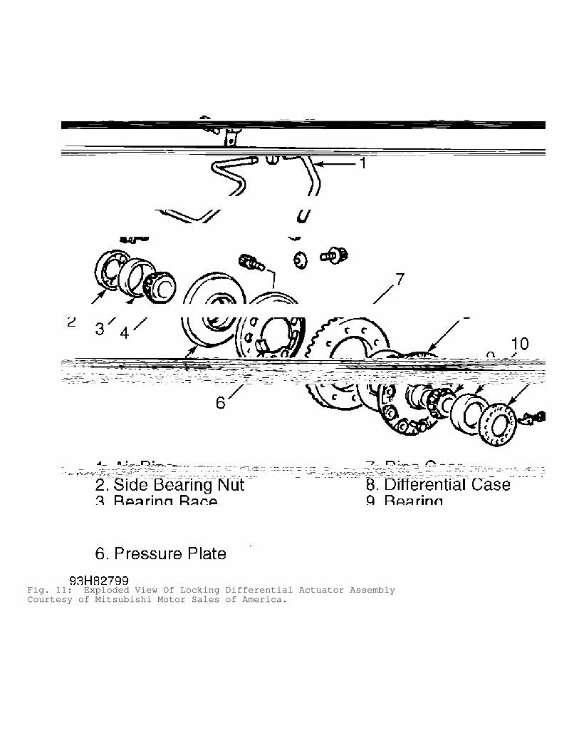
Fig. 11: Exploded View Of Locking Differential Actuator AssemblyCourtesy of Mitsubishi Motor Sales of America.
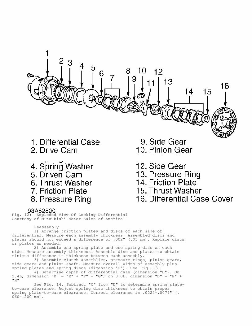
Fig. 12: Exploded View Of Locking DifferentialCourtesy of Mitsubishi Motor Sales of America.
Reassembly 1) Arrange friction plates and discs of each side ofdifferential. Measure each assembly thickness. Assembled discs andplates should not exceed a difference of .002" (.05 mm). Replace discsor plates as needed. 2) Assemble one spring plate and one spring disc on eachside. Measure assembly thickness. Assemble disc and plates to obtainminimum difference in thickness between each assembly. 3) Assemble clutch assemblies, pressure rings, pinion gears,side gears and pinion shaft. Measure overall width of assembly plusspring plates and spring discs (dimension "C"). See Fig. 13. 4) Determine depth of differential case (dimension "D"). On2.4L, dimension "D" = "E" + "F" - "G"; on 3.0L, dimension "D" = "E" +"H" See Fig. 14. Subtract "C" from "D" to determine spring plate-to-case clearance. Adjust spring disc thickness to obtain properspring plate-to-case clearance. Correct clearance is .0024-.0079" (.060-.200 mm).
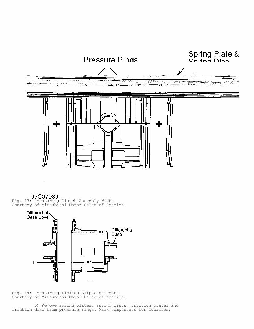
Fig. 13: Measuring Clutch Assembly WidthCourtesy of Mitsubishi Motor Sales of America.
Fig. 14: Measuring Limited Slip Case DepthCourtesy of Mitsubishi Motor Sales of America.
5) Remove spring plates, spring discs, friction plates andfriction disc from pressure rings. Mark components for location.
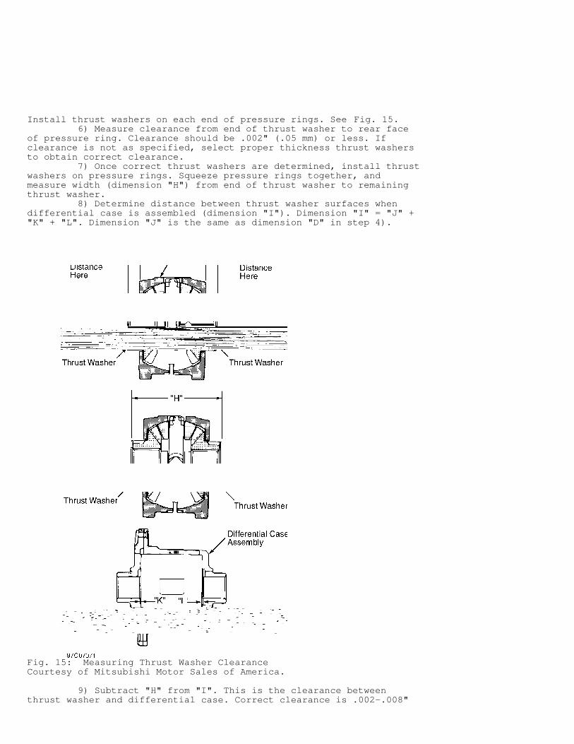
Install thrust washers on each end of pressure rings. See Fig. 15. 6) Measure clearance from end of thrust washer to rear faceof pressure ring. Clearance should be .002" (.05 mm) or less. Ifclearance is not as specified, select proper thickness thrust washersto obtain correct clearance. 7) Once correct thrust washers are determined, install thrustwashers on pressure rings. Squeeze pressure rings together, andmeasure width (dimension "H") from end of thrust washer to remainingthrust washer. 8) Determine distance between thrust washer surfaces whendifferential case is assembled (dimension "I"). Dimension "I" = "J" +"K" + "L". Dimension "J" is the same as dimension "D" in step 4).
Fig. 15: Measuring Thrust Washer ClearanceCourtesy of Mitsubishi Motor Sales of America.
9) Subtract "H" from "I". This is the clearance betweenthrust washer and differential case. Correct clearance is .002-.008"
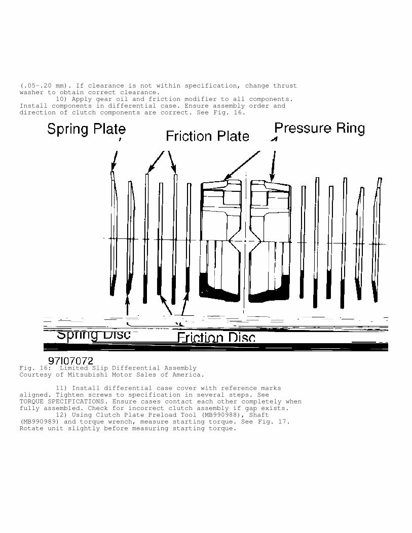
(.05-.20 mm). If clearance is not within specification, change thrustwasher to obtain correct clearance. 10) Apply gear oil and friction modifier to all components.Install components in differential case. Ensure assembly order anddirection of clutch components are correct. See Fig. 16.
Fig. 16: Limited Slip Differential AssemblyCourtesy of Mitsubishi Motor Sales of America.
11) Install differential case cover with reference marksaligned. Tighten screws to specification in several steps. SeeTORQUE SPECIFICATIONS. Ensure cases contact each other completely whenfully assembled. Check for incorrect clutch assembly if gap exists. 12) Using Clutch Plate Preload Tool (MB990988), Shaft(MB990989) and torque wrench, measure starting torque. See Fig. 17.Rotate unit slightly before measuring starting torque.
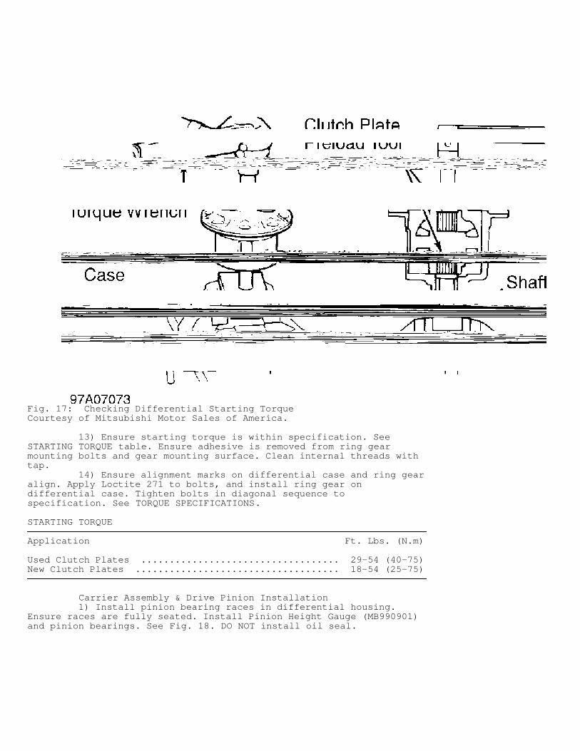
Fig. 17: Checking Differential Starting TorqueCourtesy of Mitsubishi Motor Sales of America.
13) Ensure starting torque is within specification. SeeSTARTING TORQUE table. Ensure adhesive is removed from ring gearmounting bolts and gear mounting surface. Clean internal threads withtap. 14) Ensure alignment marks on differential case and ring gearalign. Apply Loctite 271 to bolts, and install ring gear ondifferential case. Tighten bolts in diagonal sequence tospecification. See TORQUE SPECIFICATIONS.
STARTING TORQUE�������������������������������������������������������������������������������������������������������������������������������������������
Application Ft. Lbs. (N.m)
Used Clutch Plates ................................... 29-54 (40-75)New Clutch Plates .................................... 18-54 (25-75)�������������������������������������������������������������������������������������������������������������������������������������������
Carrier Assembly & Drive Pinion Installation 1) Install pinion bearing races in differential housing.Ensure races are fully seated. Install Pinion Height Gauge (MB990901)and pinion bearings. See Fig. 18. DO NOT install oil seal.
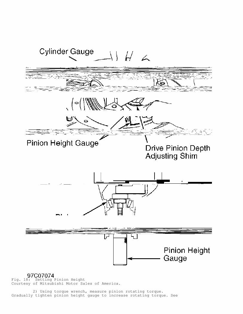
Fig. 18: Setting Pinion HeightCourtesy of Mitsubishi Motor Sales of America.
2) Using torque wrench, measure pinion rotating torque.Gradually tighten pinion height gauge to increase rotating torque. See
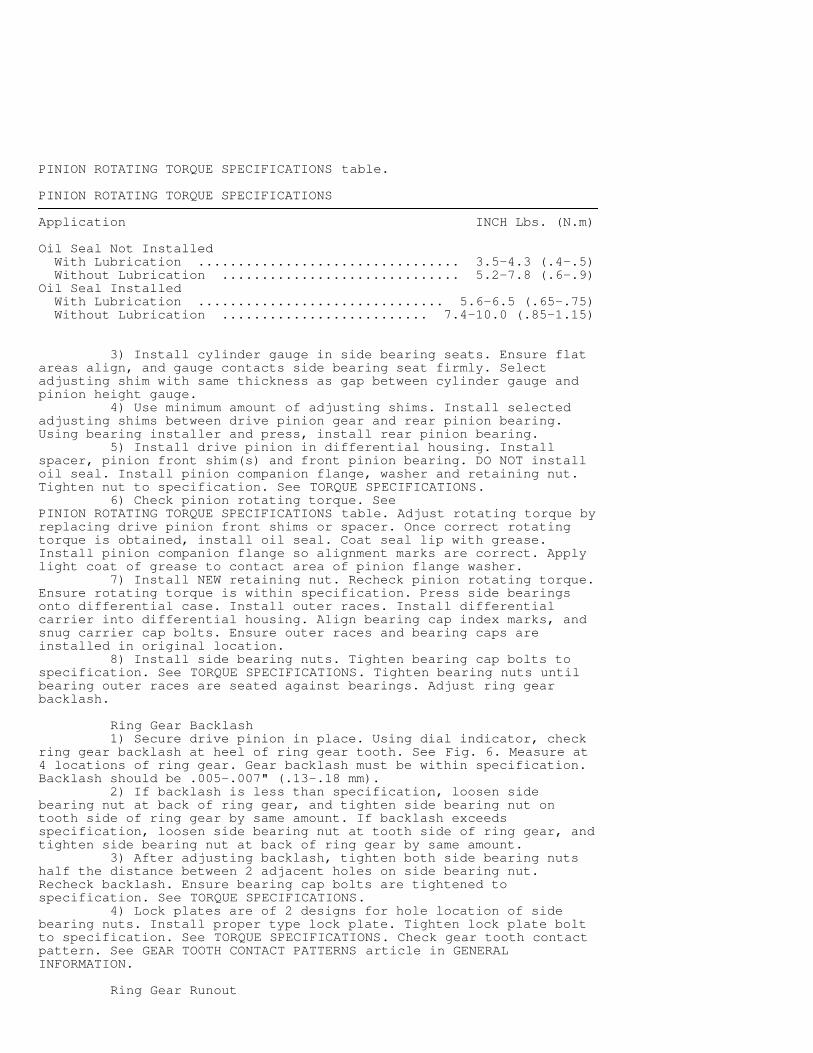
PINION ROTATING TORQUE SPECIFICATIONS table.
PINION ROTATING TORQUE SPECIFICATIONS�������������������������������������������������������������������������������������������������������������������������������������������
Application INCH Lbs. (N.m)
Oil Seal Not Installed With Lubrication ................................. 3.5-4.3 (.4-.5) Without Lubrication .............................. 5.2-7.8 (.6-.9)Oil Seal Installed With Lubrication ............................... 5.6-6.5 (.65-.75) Without Lubrication .......................... 7.4-10.0 (.85-1.15)�������������������������������������������������������������������������������������������������������������������������������������������
3) Install cylinder gauge in side bearing seats. Ensure flatareas align, and gauge contacts side bearing seat firmly. Selectadjusting shim with same thickness as gap between cylinder gauge andpinion height gauge. 4) Use minimum amount of adjusting shims. Install selectedadjusting shims between drive pinion gear and rear pinion bearing.Using bearing installer and press, install rear pinion bearing. 5) Install drive pinion in differential housing. Installspacer, pinion front shim(s) and front pinion bearing. DO NOT installoil seal. Install pinion companion flange, washer and retaining nut.Tighten nut to specification. See TORQUE SPECIFICATIONS. 6) Check pinion rotating torque. SeePINION ROTATING TORQUE SPECIFICATIONS table. Adjust rotating torque byreplacing drive pinion front shims or spacer. Once correct rotatingtorque is obtained, install oil seal. Coat seal lip with grease.Install pinion companion flange so alignment marks are correct. Applylight coat of grease to contact area of pinion flange washer. 7) Install NEW retaining nut. Recheck pinion rotating torque.Ensure rotating torque is within specification. Press side bearingsonto differential case. Install outer races. Install differentialcarrier into differential housing. Align bearing cap index marks, andsnug carrier cap bolts. Ensure outer races and bearing caps areinstalled in original location. 8) Install side bearing nuts. Tighten bearing cap bolts tospecification. See TORQUE SPECIFICATIONS. Tighten bearing nuts untilbearing outer races are seated against bearings. Adjust ring gearbacklash.
Ring Gear Backlash 1) Secure drive pinion in place. Using dial indicator, checkring gear backlash at heel of ring gear tooth. See Fig. 6. Measure at4 locations of ring gear. Gear backlash must be within specification.Backlash should be .005-.007" (.13-.18 mm). 2) If backlash is less than specification, loosen sidebearing nut at back of ring gear, and tighten side bearing nut ontooth side of ring gear by same amount. If backlash exceedsspecification, loosen side bearing nut at tooth side of ring gear, andtighten side bearing nut at back of ring gear by same amount. 3) After adjusting backlash, tighten both side bearing nutshalf the distance between 2 adjacent holes on side bearing nut.Recheck backlash. Ensure bearing cap bolts are tightened tospecification. See TORQUE SPECIFICATIONS. 4) Lock plates are of 2 designs for hole location of sidebearing nuts. Install proper type lock plate. Tighten lock plate boltto specification. See TORQUE SPECIFICATIONS. Check gear tooth contactpattern. See GEAR TOOTH CONTACT PATTERNS article in GENERALINFORMATION.
Ring Gear Runout
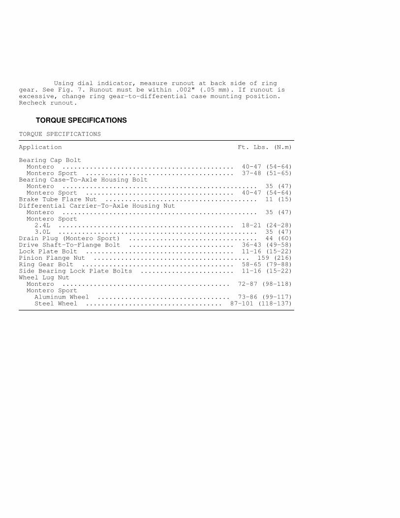
Using dial indicator, measure runout at back side of ringgear. See Fig. 7. Runout must be within .002" (.05 mm). If runout isexcessive, change ring gear-to-differential case mounting position.Recheck runout.
TORQUE SPECIFICATIONS
TORQUE SPECIFICATIONS�������������������������������������������������������������������������������������������������������������������������������������������
Application Ft. Lbs. (N.m)
Bearing Cap Bolt Montero ............................................ 40-47 (54-64) Montero Sport ...................................... 37-48 (51-65)Bearing Case-To-Axle Housing Bolt Montero .................................................. 35 (47) Montero Sport ...................................... 40-47 (54-64)Brake Tube Flare Nut ....................................... 11 (15)Differential Carrier-To-Axle Housing Nut Montero .................................................. 35 (47) Montero Sport 2.4L ............................................. 18-21 (24-28) 3.0L ................................................... 35 (47)Drain Plug (Montero Sport) ................................. 44 (60)Drive Shaft-To-Flange Bolt ........................... 36-43 (49-58)Lock Plate Bolt ...................................... 11-16 (15-22)Pinion Flange Nut ........................................ 159 (216)Ring Gear Bolt ....................................... 58-65 (79-88)Side Bearing Lock Plate Bolts ........................ 11-16 (15-22)Wheel Lug Nut Montero ........................................... 72-87 (98-118) Montero Sport Aluminum Wheel .................................. 73-86 (99-117) Steel Wheel ................................... 87-101 (118-137)�������������������������������������������������������������������������������������������������������������������������������������������