Embed Size (px)
Citation preview
HAL Id: hal-00509083https://hal.archives-ouvertes.fr/hal-00509083
Submitted on 14 Jan 2015
HAL is a multi-disciplinary open accessarchive for the deposit and dissemination of sci-entific research documents, whether they are pub-lished or not. The documents may come fromteaching and research institutions in France orabroad, or from public or private research centers.
L’archive ouverte pluridisciplinaire HAL, estdestinée au dépôt et à la diffusion de documentsscientifiques de niveau recherche, publiés ou non,émanant des établissements d’enseignement et derecherche français ou étrangers, des laboratoirespublics ou privés.
Diffraction-limited optics for single-atom manipulationYvan R. P. Sortais, H Marion, C Tuchendler, M Lamare, P Fournet, CArmellin, R Mercier, G Messin, Antoine Browaeys, Philippe Grangier
To cite this version:Yvan R. P. Sortais, H Marion, C Tuchendler, M Lamare, P Fournet, et al.. Diffraction-limited opticsfor single-atom manipulation. Physical Review A, American Physical Society, 2007, 75, pp.013406.<10.1103/PhysRevA.75.013406>. <hal-00509083>

Diffraction-limited optics for single-atom manipulation
Y. R. P. Sortais,* H. Marion, C. Tuchendler, A. M. Lance, M. Lamare, P. Fournet, C. Armellin, R. Mercier, G. Messin,A. Browaeys, and P. Grangier
Laboratoire Charles Fabry de l’Institut d’Optique, Campus Polytechnique, RD 128, 91127 Palaiseau Cedex, France†
�Received 4 October 2006; published 8 January 2007�
We present an optical system designed to capture and observe a single neutral atom in an optical dipole trap,created by focusing a laser beam using a large-numerical-aperture �NA=0.5� aspheric lens. We experimentallyevaluate the performance of the optical system and show that it is diffraction limited over a broad spectralrange ��200 nm� with a large transverse field �±25 �m�. The optical tweezer created at the focal point of thelens is able to trap single atoms of 87Rb and to detect them individually with a large collection efficiency. Wemeasure the oscillation frequency of the atom in the dipole trap and use this value as an independent deter-mination of the waist of the optical tweezer. Finally, we produce with the same lens two dipole traps separatedby 2.2 �m and show that the imaging system can resolve the two atoms.
DOI: 10.1103/PhysRevA.75.013406 PACS number�s�: 32.80.Lg, 32.80.Pj, 42.15.Eq
I. INTRODUCTION
The observation and manipulation of a few individual par-ticles are at the core of many present experiments in atomicand molecular physics, quantum optics, and quantum infor-mation, as well as in biology and chemistry. Quite often,these experiments rely on high numerical aperture opticswhich collect a very weak fluorescence signal emitted by theparticles. These optics generally operate at the diffractionlimit in order to image small objects with a high spatialresolution. As a few examples, the objects may be single ionsin a Paul trap �1�, single neutral atoms in microscopic opticaldipole traps �2�, Bose-Einstein condensates in a double wellpotential �3�, or single fluorophores in a biological mem-brane �4�. The high resolution of the imaging optics allowsthe observation of periodic chains of ions �5,6� or arrays �7�of microscopic objects, with distances between them as smallas a few microns.
Many of these experiments rely on the ability not only toobserve, but also to trap and manipulate the particles. Largenumerical aperture optics, when diffraction limited, can fo-cus laser beams down to submicron spots that can be used assharp optical tweezers �8�. In atomic physics, this strong con-finement can be used to trap exactly one atom in the tweezer�2,9�, with high oscillation frequencies due to the sharp fo-cusing. Using independently controlled optical tweezers si-multaneously, one can control the collision between two �ormore� individual particles �10�. This approach has alreadybeen implemented to investigate interactions between mov-ing biological objects �11�, and offers an interesting perspec-tive to realize quantum logic operations between a few coldneutral atoms or ions �5,12�.
In the case of atoms or ions, the design of large numericalaperture optics requires one to take into account the ultrahighvacuum environment that is necessary to produce and ma-
nipulate them. The optics may be either inside the vacuumchamber—and then must be bakable and vacuumcompatible—or outside—but then the focused beam must gothrough a vacuum window, which generally creates signifi-cant aberrations. Another constraint arises from the arrange-ment of the trapping system surrounding the particles �e.g.,electrodes for an ion trap or laser cooling beams�, whichusually requires a long enough working distance of at least afew millimeters. These constraints add up to the require-ments of large numerical aperture and diffraction limited per-formance, and often lead to a rather complicated design andmanufacturing of vacuum compatible custom objectives.
In this paper, we describe and characterize a simple opti-cal system, based on the combination of a large numericalaperture aspheric lens placed inside the vacuum chamber,and a few standard lenses placed outside. This system com-bines the powerful techniques of optical tweezers and confo-cal microscopy to trap, manipulate, and observe single ultra-cold 87Rb atoms. The simplicity and low cost of the designcompare favorably with custom objectives based on spheri-cal lenses �13,14� and suggest broad applicability to otherfields of research where excellent spatial resolution is criti-cal. The numerical aperture is NA=0.5 and, for a fixed work-ing distance on the order of a centimeter, it performs at dif-fraction limit over a large spectral range, from 700 up to880 nm �15�. We take advantage of this property to bothfocus the tweezer beam at a wavelength of 850 nm, and col-lect fluorescence light at 780 nm through the same lens.
The paper is organized as follows. Section II details therequirements of the system and describes the optical setup.In Sec. III the performance of the tweezer is characterizedusing optical techniques. Section IV explains how to trap anddetect a single atom at the focal point of the tweezer, andSec. V how to measure the oscillation frequency of one atomin the trap. This method provides a way to probe the lightfield locally and to perform an independent measurement ofthe laser beam waist at the focal spot.
II. REQUIREMENTS AND DESIGNOF THE OPTICAL SYSTEM
Trapping a single atom in an optical tweezer leads to thefollowing requirements for our objective lens. First, control-
*Electronic address: [email protected]†Laboratoire Charles Fabry is an “Unité Mixte de Recherche” of
Institut d’Optique Graduate School, Centre National de la Recher-che Scientifique, and Université Paris-Sud.
PHYSICAL REVIEW A 75, 013406 �2007�
1050-2947/2007/75�1�/013406�7� ©2007 The American Physical Society013406-1
ling the evolution of the atom, or its interactions with anotheratom, requires that the trap size be smaller than a few mi-crons, i.e., that the objective be diffraction limited while hav-ing a numerical aperture as large as possible. In particular,our method for single atom trapping relies on a “collisionalblockade mechanism” �16�: in a very small trap, the two-body loss rate is so high that if an atom is already trapped, asecond atom entering the trap leads to a fast inelastic colli-sion and, eventually, to the loss of the two atoms. Second,loading of the tweezer is performed by focusing the laserbeam into a reservoir of laser cooled atoms, an optical mo-lasses in our case. In practice, this implies that the focusinglens has a large enough working distance to allow for opticalaccess of the cooling beams, typically at least 5 to 10 mm isdesirable. Third, the laser used to produce the optical tweezeris far off-resonance at 850 nm, in order to avoid heating anddecoherence of the trapped atom due to spontaneous emis-sion. On the other hand, the atom is probed by exciting theD2 transition and collecting the fluorescence at 780 nm, witha dichroic plate separating the two radiations. Since it isconvenient to have both beams going through the same as-pheric lens, a third requirement is that the system be diffrac-tion limited over a broad spectral range while keeping theworking distance constant �17�. Fourth, in view of futureexperiments using several single atoms trapped in adjacenttweezers, it is also desirable that the objective remains dif-fraction limited off axis, which requires a large enough trans-verse field. For instance, a field of view of ±25 �m and aresolution of 2 �m �see below� allows one to easily addressseveral hundreds of traps. Designing arbitrary arrays couldbe achieved, for example, by combining our large NA lensand a spatial phase modulator placed on the incoming laserbeam �7�, or by using appropriate optical lattices �18�.
The requirements enumerated above can be fulfilled bycombining a sufficient number of spherical lenses. This is thecase for the microscope objective that we designed for ourfirst generation experiment dedicated to single atom manipu-lation �13,19�. This objective consists of nine sphericallenses and has a numerical aperture NA=0.7. Tight mechani-cal constraints and careful alignment of the lenses resulted ina diffraction-limited performance with spatial resolution of0.7 �m. The transverse field is ±10 �m. The working dis-tance is 10 mm and the objective operates under ultrahighvacuum.
For simplification and scalability purposes, we have builta second generation apparatus that uses a single commercialmolded aspheric lens �20� with NA=0.5, a working distanceof �5.7 mm, and a focal length of 8 mm. This lens is manu-factured by LightPath Technologies, Inc. �21� and is diffrac-tion limited at 780 nm for an object plane at infinite distance,with a 0.25 mm thick glass plate between the lens and theimage focal plane. The absence of this glass plate results inan enhanced spherical aberration when operating the lens atan infinite conjugate ratio. However, we noticed thataberration-free operation can be restored by slightly defocus-ing the aspheric lens and operating with weakly noncolli-mated beams. Low numerical aperture lenses can providesuch beams without introducing aberrations. This beam shap-ing, which is crucial for our system, was optimized by usingan optical design software �22�.
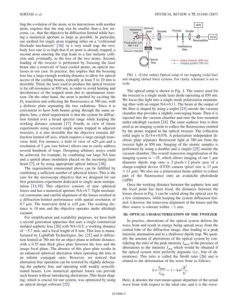
The optical setup is shown in Fig. 1. The source used forthe tweezer is a single mode laser diode operating at 850 nm.We focus this light into a single mode polarization maintain-ing fiber with an output NA=0.11. The beam at the output ofthe fiber is shaped by using a triplet �23� outside the vacuumchamber that provides a slightly converging beam. Then it isinjected into the vacuum chamber and onto the lens mountedunder ultrahigh vacuum �24�. The same aspheric lens is thenused as an imaging system to collect the fluorescence emittedby the atoms trapped in the optical tweezer. The collectionsolid angle is � /4�=0.076. A polarization independent di-chroic plate separates fluorescent light at 780 nm from thetweezer light at 850 nm. Imaging of the atomic samples isperformed by using a doublet and a singlet �25� outside thevacuum chamber. The overall transverse magnification of theimaging system is �25, which allows imaging of our 1 �mdiameter dipole trap onto a 2 pixels�2 pixels area of acharge-coupled device �CCD� camera �pixel size is 13 �m�13 �m�. We also use a polarization beam splitter to collectpart of the fluorescence onto an avalanche photodiode�APD�.
Once the working distance between the aspheric lens andthe focal point has been fixed, the distances between thelenses shown in Fig. 1 can be varied along the optical axis bya few centimeters, while keeping the system diffraction lim-ited. Likewise, the transverse alignment of the lenses and thefiber source is tolerant within �1 mm.
III. OPTICAL CHARACTERIZATION OF THE TWEEZER
In practice, aberrations of the optical system deform thewave front and result in energy being spread away from thecentral lobe of the diffraction image, thus leading to a peakintensity attenuation and to a shallower dipole trap. We quan-tify the amount of aberrations of the optical system by con-sidering the ratio of the peak intensity Iaberr in the presence ofaberrations to the intensity Istig which would be obtained ifthe optical system were perfectly stigmatic �i.e., free of ab-errations�. This ratio is called the Strehl ratio �26� and isrelated to the deformation of the wave front as follows:
S =Iaberr
Istig� 1 − 4�2�2
�2 .
Here, � denotes the root-mean-square departure of the actualwave front with respect to the ideal one, and � is the wave-
FIG. 1. �Color online� Optical setup of our trapping �solid line�and imaging �dotted lines� systems. For clarity, schematic is not toscale.
SORTAIS et al. PHYSICAL REVIEW A 75, 013406 �2007�
013406-2
length of the radiation propagating through the system. Apractical criterion is that the peak intensity attenuation S islarger than the arbitrary value 0.8 for the amount of aberra-tions to be acceptable �S�0.8�. This sets an upper limit tothe amount of aberrations that we tolerate in our system ���� /14�. For a system free of aberrations, �=0 and S=1.Experimentally, the optical tweezer was characterized inthree steps.
First, we tested the performance of the triplet and theaspheric lens separately by using a wave-front analyzer�Fizeau interferometer �26��. We find that both exhibit dif-fraction limited performance: ��� /40 for the triplet �NA=0.12� and ��� /30 for the aspheric lens �NA=0.5�, thelatter being remarkable for such a large numerical aperture.The residual deformation of the wave front is due mainly toa small spherical aberration.
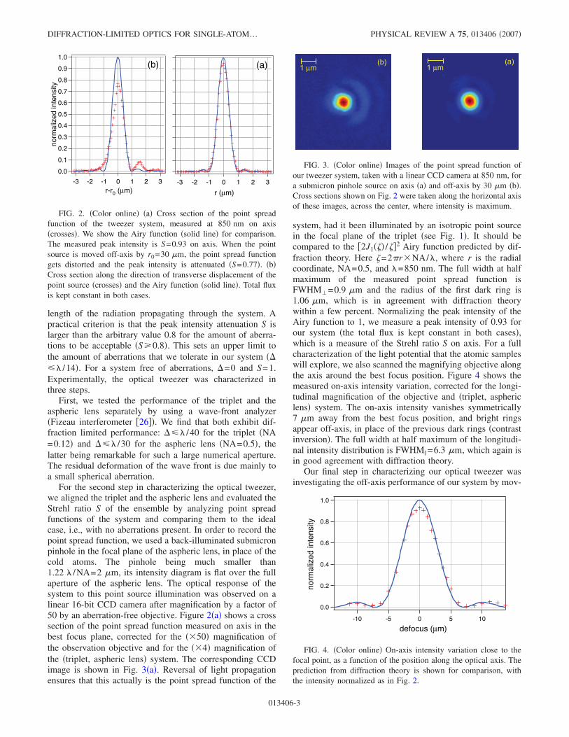
For the second step in characterizing the optical tweezer,we aligned the triplet and the aspheric lens and evaluated theStrehl ratio S of the ensemble by analyzing point spreadfunctions of the system and comparing them to the idealcase, i.e., with no aberrations present. In order to record thepoint spread function, we used a back-illuminated submicronpinhole in the focal plane of the aspheric lens, in place of thecold atoms. The pinhole being much smaller than1.22 � /NA=2 �m, its intensity diagram is flat over the fullaperture of the aspheric lens. The optical response of thesystem to this point source illumination was observed on alinear 16-bit CCD camera after magnification by a factor of50 by an aberration-free objective. Figure 2�a� shows a crosssection of the point spread function measured on axis in thebest focus plane, corrected for the ��50� magnification ofthe observation objective and for the ��4� magnification ofthe �triplet, aspheric lens� system. The corresponding CCDimage is shown in Fig. 3�a�. Reversal of light propagationensures that this actually is the point spread function of the
system, had it been illuminated by an isotropic point sourcein the focal plane of the triplet �see Fig. 1�. It should becompared to the �2J1�� /�2 Airy function predicted by dif-fraction theory. Here =2�r�NA/�, where r is the radialcoordinate, NA=0.5, and �=850 nm. The full width at halfmaximum of the measured point spread function isFWHM�=0.9 �m and the radius of the first dark ring is1.06 �m, which is in agreement with diffraction theorywithin a few percent. Normalizing the peak intensity of theAiry function to 1, we measure a peak intensity of 0.93 forour system �the total flux is kept constant in both cases�,which is a measure of the Strehl ratio S on axis. For a fullcharacterization of the light potential that the atomic sampleswill explore, we also scanned the magnifying objective alongthe axis around the best focus position. Figure 4 shows themeasured on-axis intensity variation, corrected for the longi-tudinal magnification of the objective and �triplet, asphericlens� system. The on-axis intensity vanishes symmetrically7 �m away from the best focus position, and bright ringsappear off-axis, in place of the previous dark rings �contrastinversion�. The full width at half maximum of the longitudi-nal intensity distribution is FWHM� =6.3 �m, which again isin good agreement with diffraction theory.
Our final step in characterizing our optical tweezer wasinvestigating the off-axis performance of our system by mov-
1.0
0.9
0.8
0.7
0.6
0.5
0.4
0.3
0.2
0.1
0.0
3210-1-2-3
r (µm)
1.0
0.9
0.8
0.7
0.6
0.5
0.4
0.3
0.2
0.1
0.0
norm
aliz
ed in
tens
ity
3210-1-2-3r-r0 (µm)
(a)(b)
FIG. 2. �Color online� �a� Cross section of the point spreadfunction of the tweezer system, measured at 850 nm on axis�crosses�. We show the Airy function �solid line� for comparison.The measured peak intensity is S=0.93 on axis. When the pointsource is moved off-axis by r0=30 �m, the point spread functiongets distorted and the peak intensity is attenuated �S=0.77�. �b�Cross section along the direction of transverse displacement of thepoint source �crosses� and the Airy function �solid line�. Total fluxis kept constant in both cases.
1 µm(b)
1 µm(a)
FIG. 3. �Color online� Images of the point spread function ofour tweezer system, taken with a linear CCD camera at 850 nm, fora submicron pinhole source on axis �a� and off-axis by 30 �m �b�.Cross sections shown on Fig. 2 were taken along the horizontal axisof these images, across the center, where intensity is maximum.
1.0
0.8
0.6
0.4
0.2
0.0
norm
aliz
ed in
tens
ity
-10 -5 0 5 10
defocus (µm)
FIG. 4. �Color online� On-axis intensity variation close to thefocal point, as a function of the position along the optical axis. Theprediction from diffraction theory is shown for comparison, withthe intensity normalized as in Fig. 2.
DIFFRACTION-LIMITED OPTICS FOR SINGLE-ATOM… PHYSICAL REVIEW A 75, 013406 �2007�
013406-3
ing the pinhole perpendicular to the optical axis. Figure 3shows the point spread functions measured for a pinhole,respectively, on-axis and off-axis by 30 �m. The latter dis-plays the characteristic V-shaped flare of a comatic aberra-tion. Since our system is nearly free of aberrations on axis,we determine its Strehl ratio by directly comparing the peakintensities of images taken with an off-axis and on-axis pin-hole, provided the total flux is kept constant �see Fig. 2�b��.The performance of the optical tweezer can be equivalentlyevaluated by plotting its optical modulation transfer function�MTF� that characterizes the attenuation of the various spa-tial frequencies present in a test object, due to the optics �27�.Figure 5 shows cross sections of the two-dimensional �2D�-Fourier transform of the images shown in Fig. 3 and com-pares them to the frequency response of an aberration-freesystem with similar numerical aperture: the 2D-autocorrelation function of a circular aperture. The measure-ments show that our system displays a field of ±25 �m overwhich S�0.8.
It should be noted here that the results described abovewere obtained by illuminating the system with sphericalwave fronts, issued from a submicron pinhole. The situationis slightly different for our single atom tweezer because thesystem is illuminated with a Gaussian beam provided by anoptical fiber, with a beam waist equal to the aspheric lensradius. This has two consequences: first, the diffraction ringstructure shown above is significantly damped, due to theGaussian apodization effect. Second, the point spread func-tion becomes slightly broader, with a FWHM� increased by9%, and is neither an Airy function nor purely Gaussian.
IV. DETECTION OF A SINGLE ATOM TRAPPEDIN AN OPTICAL TWEEZER
The optical tweezer described above is a powerful tool formanipulating single neutral atoms. The alignment of the op-tical tweezer onto the center region of an optical molasses ofcold 87Rb atoms indeed results in the trapping of a singleatom in the microscopic dipole trap as shown below. Theoptical molasses �28,29� is produced by six counterpropagat-
ing cooling beams at �780 nm and a Zeeman slowed beamof Rb atoms �30�, providing a large reservoir of cold atoms�with typical size �1 mm� surrounding the microscopic op-tical tweezer.
We observe the fluorescence of the trapped atoms with anavalanche photodiode �APD� used in single photon countingmode, as well as a CCD camera with low read-out noise �seeFig. 1�. We use an interference filter �centered at 780 nm,with 10 nm bandwidth� and a 400 �m diameter pinhole inconfocal configuration to reduce the background signal. Theresidual scattering of the 780 nm cooling beams in thevacuum chamber and on the optical table contributes for81% of this background signal, the remaining 19% comingfrom the background fluorescence at 780 nm by the molassesitself. We estimate the overall collection efficiency of oursystem to be �1%, taking into account the angular collectionefficiency of the lens �7.6%�, the transmission of the optics,and the quantum efficiency of the APD.
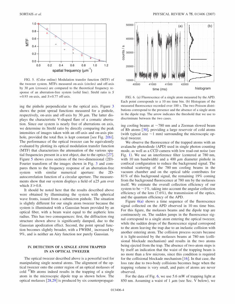
Figure 6�a� shows a time sequence of the fluorescencesignal collected on the APD observed in 10 ms time bins.For this figure, the molasses beams and the dipole trap arecontinuously on. The sudden jumps in the fluorescence sig-nal correspond to a single atom entering the optical tweezer,while the sudden drops of the fluorescence signal correspondto the atom leaving the trap due to an inelastic collision withanother entering atom. The collision process occurs becauseit is light-assisted by the molasses beams at 780 nm �colli-sional blockade mechanism� and results in the two atomsbeing ejected from the trap. The absence of two-atom steps isby itself an indication that the waist of the trapping beam isno more than a few microns, since this condition is requiredfor the collisional blockade mechanism �16�. In that case, theloss rate due to two-body collisions becomes huge when thetrapping volume is very small, and pairs of atoms are neverobserved.
For the data of Fig. 6, we use 5.6 mW of trapping light at850 nm. Assuming a waist of 1 �m �see Sec. V below�, we
1.0
0.8
0.6
0.4
0.2
0.0
MT
F
1.21.00.80.60.40.20.0
spatial frequency (µm-1
)
FIG. 5. �Color online� Modulation transfer function �MTF� ofthe tweezer system. MTFs measured on-axis �circles� and off-axisby 30 �m �crosses� are compared to the theoretical frequency re-sponse of an aberration-free system �solid line�. Strehl ratio is S=0.93 on-axis, and S=0.77 off-axis. FIG. 6. �a� Fluorescence of a single atom measured by the APD.
Each point corresponds to a 10 ms time bin. �b� Histogram of themeasured fluorescence recorded over 100 s. The two Poisson distri-butions correspond to the presence and the absence of a single atomin the dipole trap. The arrow indicates the threshold that we use todiscriminate between the two cases.
SORTAIS et al. PHYSICAL REVIEW A 75, 013406 �2007�
013406-4

calculate a trap depth of 1.5 mK, or equivalently a lightshiftof 32 MHz. The cooling beams that induce the fluorescenceof the atom are red-detuned with respect to the atomic tran-sition by 5, where =2��6�106 rad s−1 is the linewidthof the D2 transition. The fluorescent signal exhibits steps of2.7�104 photons s−1 on top of a background signal of 1.3�104 photons s−1. The analysis of the corresponding histo-grams shown in Fig. 6�b� indicates that both background andstep signals are shot-noise limited. This, together with thestep height of 2.7�104 photons s−1, allows us to discrimi-nate between the presence and the absence of an atom within10 ms with a confidence better than 99%. In the presence ofthe cooling laser beams, the storage time of the atom is lim-ited by the light-assisted collision with a second atom. It canbe varied from 100 ms up to about 10 s, depending on thedensity of the molasses cloud.
We have also measured the lifetime of the atom in theabsence of the cooling light and found a 1/e decay time of�10 s. This was measured by varying the duration Toff dur-ing which the cooling beams are switched off, and measuringthe probability to detect the atom fluorescence again rightafter Toff. This lifetime may be limited by collisions with thebackground gas �pressure in the 10−9 Pa range� as well asheating mechanisms.
Finally, we briefly address the issue of addressability andresolution of our imaging system. For this purpose, we pro-duce two tweezers by sending a second trapping beam at850 nm at a small angle in the aspheric lens. An angle of0.25 mrad, together with the focal length of 8 mm of theaspheric lens, results a 2 �m distance between the two traps.The loading of the two traps is not deterministic but we caneasily find periods of time during which two atoms arepresent at the same time in the two optical tweezers. Figure 7shows a cross section of a CCD image taken when such anevent occurs. A Gaussian fit to the peak signal produced byeach single atom indicates a waist of 0.9±0.2 �m, whichvalidates the performance of the tweezer system and the per-
formance of the imaging system altogether. We emphasizethat the two atoms are always present during the 100 msintegration time. Therefore these data correspond to realisticconditions for “reading out� a quantum register �31� with twoqubits separated by 2.2 �m. This indicates that our imagingsystem may resolve two atoms with separation as small as2 �m, within a time as short as 10 ms.
V. MEASUREMENT OF THE TRANSVERSEOSCILLATION FREQUENCY
Once the atom is trapped, we switch off the coolingbeams, while the optical tweezer is kept on. The atom oscil-lates at the bottom of the dipole trap, and measurement of itsoscillation frequency provides an in situ measurement of thetrap dimension. Knowing the power Ptrap of the trapping la-ser, and assuming that the trapping beam is Gaussian, we cancalculate from the oscillation frequency the waist w0 of theoptical tweezer:
w0 = � �
m�r2
Ptrap
�Isat
3 1+
2
3 2�1/4
,
where Isat�1.67 mW/cm2 is the saturation intensity of theD2 transition, �r is the oscillation frequency of the atommeasured in the radial plane �i.e., perpendicular to the twee-zer optical axis�, and 1�2��2.4�1013 rad s−1 � 2�2��3.2�1013 rad s−1� is the frequency detuning of the tweezerbeam relative to the D1 �D2� transition �32�.
In order to measure the oscillation frequency �r, we fol-lowed the procedure described in �33,34�. Once a singleatom is loaded in the trap, the cooling beams are switched offfor a time Toff=50 ms. Meanwhile, the dipole trap beam isswitched off and on twice, as shown in the time sequence ofFig. 8�a�. The first “off� pulse �duration t1� increases theinitial amplitude of the oscillation, once the trap is turnedback on �see details below�. After a variable period of time�t, we switch the potential off again for a fixed duration t2.After this time, we turn the molasses beams on again anddetermine whether the atom is still present or not. We thenrepeat this procedure on about 100 atoms and measure theprobability to keep the atom at the end of this sequence forvarious �t. We obtain the curve shown in Fig. 8�b�.
This curve shows oscillations that we can understand inthe following way. Assume the atom is oscillating in the trap.If the atom reaches the bottom of the trap when the second“off� pulse occurs, it will most likely leave the trap duringthe time t2 because its velocity is maximal at this point.Alternatively, if the atom reaches the apogee of its oscillationwhen the second “off” pulse occurs, it will most likely berecaptured in the trap after time t2 because its velocity isnull at the apogee. Due to the symmetry of the motion, theprobability of keeping the atom oscillates at twice the oscil-lation frequency when �t is varied. The recapture probabil-ity, which we measure when the cooling beams are switchedon again �i.e., at t=Toff�, also depends on duration t2, whichis adjusted to optimize the contrast at the beginning of theoscillation.
The role of the first “off” period is crucial in this mea-surement. Since each data point shown in Fig. 8�a� is aver-
inte
nsity
(u.
a.)
1210864position (µm)
FIG. 7. Cross section of a CCD image showing two single at-oms trapped in two adjacent optical tweezers, corrected for themagnification ��25� of the imaging system. The distance betweenthe two optical tweezers is 2.2±0.1 �m. Each peak is fitted by aGaussian model �dashed lines� and exhibits a waist w=0.9±0.2 �m. The solid line represents the sum of the fits of thetwo fluorescent signals emitted by each single atom. Vertical barsrepresent the intensity measured by each pixel of the CCD cameraduring a time window of 100 ms.
DIFFRACTION-LIMITED OPTICS FOR SINGLE-ATOM… PHYSICAL REVIEW A 75, 013406 �2007�
013406-5

aged over 100 single atoms, all these atoms must oscillate inthe trap with the same phase if one wants to see any oscilla-tions at all. The first pulse precisely fulfills this function, asexplained in Fig. 9. In this figure, we consider the phasespace defined by the position x and the velocity vx in theradial plane, assuming a harmonic motion with the frequency�r. We suppose that the initial distribution of atoms followsa Gaussian distribution, both in position and velocity. The
width of this distribution in the phase space �x ,vx /�r� de-pends on the mean energy of the atoms. During the free flightof duration t1, the initial isotropic distribution evolves to-wards an elliptical distribution �Fig. 9� because the velocitiesof the atoms remain constant when the trap is switched off.In phase space, the ellipse is pulled along the x axis and itslong axis makes an angle � that decreases with time: thelonger the duration t1, the “flatter” the ellipse, keeping aconstant area in phase space. For an oscillation frequencyaround 119 kHz and t1=1.3 �s, we calculate that the angleof the ellipse is ��32° and the ratio between the lengths ofthe long axis and the small axis is �2.6. When the trap isturned back on at the end of the free flight period, the atomsthat are still in the trap oscillate with a larger amplitude, andthey are now almost all in phase with each other. We notethat for the chosen t1, only the radial oscillation frequencyis excited because along the longitudinal axis the free expan-sion remains quite small compared to the initial size of theatomic “cloud.”
We fit the data shown in Fig. 8�b� with a damped sinefunction and measure a radial oscillation frequency �r /2�=119±3 kHz. The damping of the oscillation is attributed tothe anharmonicity of the trap potential explored by the atomafter the first “off” period �33,34�. Since the trapping beampower was measured to be Ptrap=5.6±0.1 mW and assuminga Gaussian intensity distribution at the focal point of the trapbeam, we infer a beam waist w0=1.03±0.01 �m. From thisresult we calculate a trap depth U0=1.5 mK and a longitudi-nal oscillation frequency �z /2�=22 kHz. The waist w0 ex-tracted from the data is in good agreement with the value of0.9±0.2 �m, obtained by imaging a single atom on a CCDcamera, as presented in Sec. IV.
VI. CONCLUSION
In conclusion, we have demonstrated a diffraction limitedoptical system with a large numerical aperture �NA=0.5�that acts as a sharp optical tweezer used to trap a single atom.The large collection efficiency of this same lens allowssingle atom detection with confidence better than 99% within10 ms, and resolves atoms at the microscopic level. Theresolution is good enough that we can resolve two atomstrapped in two tweezers separated by less than 2 �m. Thissystem is based on low cost commercial lenses and is rela-tively tolerant to small misalignments. It also provides alarge field of view �±25 �m� and a large spectral range overwhich it remains diffraction limited. We believe that this sys-tem is thus a valuable tool for experiments manipulating andobserving single particles. It should be useful for applica-tions in quantum computing using neutral atoms and also foraddressing strings of individual ions.
ACKNOWLEDGMENTS
We acknowledge support from the Integrated Project“SCALA” which is part of the European IST/FET/QIPC Pro-gram, from Institut Francilien des Atomes Froids �IFRAF�,and from ARDA/DTO. Y.R.P.S. and H.M. were supported byIFRAF and CNRS, and A.M.L. also by IFRAF.
100
80
60
40
20
0Rec
aptu
re p
roba
bilit
y (%
)
1211109876543210
Time (µs)
(b)
FIG. 8. �Color online� Oscillations of a single atom in the dipoletrap. �a� shows the time sequence used for this measurement. Dipoletrap is switched off twice, during t1�1.3 �s and t2�6.2 �s. Inthe time interval �t separating these two “off” pulses, the dipoletrap is switched on again. �b� shows the probability to keep theatom after this time sequence. Each point corresponds to 100 suc-cessful events �i.e., with one single atom at the beginning of thesequence� for a given time delay �t. Error bars are statistical. Thesolid line is a damped sine fit to the data, showing that the atomoscillates with frequency �r /2�=119±3 kHz.
-0.4
-0.2
0
0.2
0.4
-0.4 -0.2 0 0.2 0.4 0.6-0.6 -0.4 -0.2 0 0.2 0.4 0.6-0.6
(a) (b)
x (µm)
v /ω
(µ
m)
x
x (µm)
θ
r
FIG. 9. Monte Carlo simulation of the evolution of 2000 atomsin the radial plane of the tweezer, using phase space representation.�a� The atoms are distributed with an initial symmetric Gaussiandistribution before the first “off” period of duration t1. The circlerepresents one standard deviation of the distribution. �b� The distri-bution evolves towards an ellipse with angle � during the free flightof duration t1. As a consequence, the atoms oscillate in phasewhen they are recaptured in the trap.
SORTAIS et al. PHYSICAL REVIEW A 75, 013406 �2007�
013406-6
�1� W. Neuhauser, M. Hohenstatt, P. E. Toschek, and H. Dehmelt,Phys. Rev. A 22, 1137 �1980�.
�2� N. Schlosser, G. Reymond, I. Protsenko, and P. Grangier, Na-ture �London� 411, 1024 �2001�.
�3� M. Albiez, R. Gati, J. Fölling, S. Hunsmann, M. Cristiani, andM. K. Oberthaler, Phys. Rev. Lett. 95, 010402 �2005�.
�4� J. Wenger, H. Rigneault, J. Dintinger, D. Marguet, and P.-F.Lenne, J. Biol. Phys. 32, SN1 �2006�.
�5� C. F. Roos, G. P. T. Lancaster, M. Riebe, H. Häffner, W.Hänsel, S. Gulde, C. Becher, J. Eschner, F. Schmidt-Kaler, andR. Blatt, Phys. Rev. Lett. 92, 220402 �2004�.
�6� M. G. Raizen, J. M. Gilligan, J. C. Bergquist, W. M. Itano, andD. J. Wineland, Phys. Rev. A 45, 6493 �1992�.
�7� S. Bergamini, B. Darquié, M. Jones, L. Jacubowiez, A.Browaeys, and P. Grangier, J. Opt. Soc. Am. B 21, 1889�2004�.
�8� D. G. Grier, Nature �London� 424, 810 �2003�.�9� M. Weber, J. Volz, K. Saucke, C. Kurtsiefer, and H. Wein-
fürter, Phys. Rev. A 73, 043406 �2006�.�10� T. Calarco, H.-J. Briegel, D. Jaksch, J. I. Cirac, and P. Zoller, J.
Mod. Opt. 47, 2137 �2000�.�11� M. Mammen, K. Helmerson, R. Kishore, S.-K. Choi, W. D.
Phillips, and G. M. Whitesides, Chem. Biol. 3, 757 �1996�.�12� U. Dorner, T. Calarco, P. Zoller, A. Browaeys, and P. Grangier,
J. Opt. B: Quantum Semiclassical Opt. 7, S341 �2005�.�13� K. Vigneron, Thèse de Doctorat de l’Université Paris XI, Or-
say, 1998 �unpublished�; N. Schlosser, Thèse de Doctorat del’Université Paris XI, Orsay, 2001 �unpublished�.
�14� W. Alt, Optik �Stuttgart� 113, 142 �2002�.�15� The numerical aperture is NA=n sin � where n is the refrac-
tion index of the medium in which the lens is working, and �is half of the angular aperture of the lens. Here n=1 since ourlens operates under vacuum, and �=30°.
�16� N. Schlosser, G. Reymond, and P. Grangier, Phys. Rev. Lett.89, 023005 �2002�.
�17� This does not mean that the optics is achromatic: the images atdifferent wavelengths are in different planes outside thevacuum chamber, but this is not a limitation since they corre-spond to different light beams.
�18� S. Peil, J. V. Porto, B. Laburthe Tolra, J. M. Obrecht, B. E.King, M. Subbotin, S. L. Rolston, and W. D. Phillips, Phys.Rev. A 67, 051603�R� �2003�.
�19� B. Darquié, M. P. A. Jones, J. Dingjan, J. Beugnon, S. Ber-gamini, Y. Sortais, G. Messin, A. Browaeys, and P. Grangier,Science 309, 454 �2005�.
�20� Model 350240 from LightPath Technologies, Inc., 2603 Chal-lenger Tech Court, Suite 100, Orlando, FL 32826, USA; web-site: http://www.lightpath.com
�21� Mention of a specific company does not constitute an endorse-ment by Institut d’Optique Graduate School.
�22� Code V 9.60 from Optical Research Associates, 3280 EastFoothill Boulevard, Suite 300, Pasadena, CA 91107-3103,USA; website http://www.opticalres.com
�23� Model 09 LAM 126 from Melles Griot, 55 Science Parkway,Rochester, NY 14620, USA; website: http://www.mellesgriot.com
�24� The vacuum chamber was baked up to 130 °C for 2 days. Theresulting pressure is less than 10−8 Pa.
�25� From Melles Griot: doublet model 01 LAO 226; singlet model01 LDX 141.
�26� M. Born and E. Wolf, Principles of Optics �Cambridge Uni-versity Press, Cambridge, England, 2003�.
�27� The incoherent optical modulation transfer function is the 2D-Fourier transform of the energy point spread function �26�. Thelatter being normalized to unity flux, the MTF equals 1 for nullspatial frequency.
�28� P. D. Lett, W. D. Phillips, S. L. Rolston, C. E. Tanner, R. N.Watts, and C. I. Westbrook, J. Opt. Soc. Am. B 6, 2084 �1989�.
�29� J. Dalibard and C. Cohen-Tannoudji, J. Opt. Soc. Am. B 6,2023 �1989�.
�30� W. D. Phillips and H. Metcalf, Phys. Rev. Lett. 48, 596�1982�.
�31� I. Dotsenko, W. Alt, M. Khudaverdyan, S. Kuhr, D. Meschede,Y. Miroshnychenko, D. Schrader, and A. Rauschenbeutel,Phys. Rev. Lett. 95, 033002 �2005�.
�32� R. Grimm, M. Weidemüller, and Y. B. Ovchinnikov, in Ad-vances in Atomic, Molecular and Optical Physics, edited by B.Bederson and H. Walther �Academic Press, San Diego, 2000�,Vol. 42, p. 95.
�33� G. Reymond, N. Schlosser, I. Protsenko, and P. Grangier, Phi-los. Trans. R. Soc. London, Ser. A 361, 1527 �2003�.
�34� B. Darquié, Thèse de Doctorat de l’Université Paris XI, Orsay,2005 �unpublished�, available online at http://tel.ccsd.cnrs.fr/tel-00011604/en/
DIFFRACTION-LIMITED OPTICS FOR SINGLE-ATOM… PHYSICAL REVIEW A 75, 013406 �2007�
013406-7