Embed Size (px)
Citation preview

Diffuse reflection of ceramics coated withdielectric thin films
Gang Xu, Masato Tazawa, Ping Jin, and Kazuki Yoshimura
We have studied the diffuse reflection properties of ceramics in the presence of dielectric thin films on thesurface. A simple optical model was proposed in which interference effects in a thin film were consideredfor light scattered out of a ceramic in various directions. Measurements were performed on angle-resolved reflection spectra of a thin-film-coated alumina ceramic in the case of normal incidence. Theyshowed that the presence of the thin film on the ceramic’s surface modified the angular distributions ofscattered radiation from that of a bare ceramic, which suggested a way to tailor the scattering propertiesof a diffuse reflector as needed. © 2003 Optical Society of America
OCIS codes: 120.5700, 290.1990, 310.1620, 230.0250.
1. Introduction
There is continuing interest in modification of theoptical scattering properties of diffuse reflectorswhen environmental conditions change. Under-standing these modifications leads to awareness ofthe underlying mechanisms that affect the scatter-ing, which is beneficial for some practical applica-tions such as remote sensing1,2 and computer vision.3
The importance of an additional layer on the sur-face of the reflector has been recognized. Jezek andKoh2 found that a water or ice layer on top of a diffusereflector would change the angular distribution of thescattered radiation. In their studies the layer wasmuch thicker ��1 mm� than the probe wavelength�� � 0.6238 �m�, and the interface between the re-flector and the layer was neglected. Wolff3 studiedanother diffuse reflector with a smooth surface. Hestressed that this surface could greatly influence dif-fuse reflection because Fresnel attenuation and Snellrefraction occur at the reflector–air boundary. Oneis then led to inquire what the situation is if a thinfilm is coated onto a smooth diffuse reflector, which isthe subject of our investigation here.
There is another practical reason for such an in-
The authors are with the National Institute of Advanced Indus-trial Science and Technology, 2266-98, Shidami, Moriyama-ku,Nagoya 463-8560, Japan. M. Tazawa’s e-mail address [email protected].
Received 22 May 2002; revised manuscript received 29 October2002.
0003-6935�03�071352-08$15.00�0© 2003 Optical Society of America
1352 APPLIED OPTICS � Vol. 42, No. 7 � 1 March 2003
vestigation. The results may be applied to clarifythe effect of a buffer layer on optical confinement in akind of crystalline silicon solar cell that uses a ce-ramic substrate.4 The buffer layer is coated onto theceramic to improve the quality of the silicon film andto protect it from contamination.5–7 Obviously,the optical properties of the ceramic as well as ofthe buffer layer may significantly influence the ef-fect of optical confinement. Several groups ofresearchers8–10 have made studies of this issue; theyconcentrated mainly on the substrate. However, therole of the buffer layer deserves more attention. Re-cently we carried out a numerical calculation of op-tical behavior in an alumina-based cell with bufferlayers of Si3N4 and SiO2 and explored the possibilitythat the buffer could enhance optical confinement.11
Further, we pointed out that the optimization of thebuffer layer is of nearly the same importance as thatof the substrate.12
For these purposes, here we study the changes inangular distribution of scattering light of a ceramicbefore and after it has been coated with a thin film.We first propose an optical model in which the inter-ference effects in the thin film for scattering light arefully considered. Measurements are then per-formed of angle-resolved reflection spectra of analumina-coated ceramic in circumstances of normalincidence. Finally, we interpret the experimentalresults based on the proposed theoretical model.
2. Theoretical Consideration
Only few authors have considered the effect of sur-face conditions on light scattering from a light-scattering medium.3,13,14 In practice, once the
surface is assumed sufficiently smooth on a scalecomparable to the wavelength, light is reflected bothspecularly from the surface and diffusely from thesubsurface. Further, the presence of an interfacewith the medium also influences the distribution ofscattering light; Fresnel attenuation and Snell re-fraction take effect at the medium’s boundary.
We deal with the case of a dielectric thin filmcoated upon the optically smooth surface of the scat-tering medium, a ceramic. Conceivably, the bidirec-tional reflectance in this case is a consequence mainlyof three processes, as shown schematically in Fig. 1:
�1� Specular reflection and transmission of lightincident from air.
�2� Volume scattering in the ceramic. Lighttransmitted from the upper layer is scattered in var-ious directions, forming an angular distribution ofintensity.
�3� Emission of scattering light from within theceramic.
Because the phase difference of light through adielectric thin film depends on the incident angle,scattering light emitted in different directions yieldsdifferent states. At the same time, the scatteringangle in the ceramic is also changed after transmis-sion into air. These two factors lead to a redistribu-tion of diffuse intensity compared with thedistribution within the ceramics.
If a collimated beam of power P0 is incident uponthe medium at an angle i relative to the surface nor-mal, specularly reflected fraction Psr from the thinfilm and transmitted fraction Pst into the ceramic willbe, respectively,
Psr � P0 R�i�, (1a)
Pst � P0 T�i�, (1b)
where R�i� and T�i� are, respectively, the specularreflectance and transmittance averaged over the twodirections of polarization. They are described by theregular theory of optical multilayers.
The transmitted radiation power will be scatteredin various directions inside the ceramic. Assumingdiffuse-reflectance function r�i�, e��, the powerPdiff�d�� that is scattered into an infinitesimal solidangle d�� to a direction with zenith angle e� in theceramic is
Pdiff�d�� � P0 T�i�r�i�, e��cos�e��d��, (2)
where a prime refers to a corresponding quantityinside the ceramic.
When the light refracts into air through the dielec-tric film at emitting �or scattering� angle e, powerPdiff�d�� will be attenuated by T�e�� �the transmit-tance from the ceramic to air�, and solid angle d��will also be modified on transmission in accordancewith Snell’s law,3 i.e.,
d�� �cos�e�
n2 cos�e��d�, (3)
in which d�, an infinitesimal solid angle in air, cor-responds to d�� and n is the refractive index of theceramic. So the diffuse power Pdiffd� in air is givenby
Pdiffd� � Pdiff�d��
�1n2 P0 T�i�r�i�, e��T�e��cos�e�d�. (4)
Combining Eqs. �1� and �4�, we can obtain an expres-sion for reflected power Psd, which consists of bothspecular and diffuse components:
Psdd� � P0 R�i��e � i�
�Kn2 P0 T�i�r�i�, e��T�e��cos�e�d�, (5)
in which �e i� is the delta function that specifiesthe location of the specular component in the princi-pal plane containing the incident plane and the re-flection plane, and i� and e� are related to angles i ande through Snell’s laws, sin�i� � n sin�i�� and sin�e� �n sin�e��, respectively. The additional factor K takesaccount of the multiple internal reflection that occursat the ceramic–film boundary. It is nearly constant,with a value larger than unity under the assumptionof isotropic scattering.
Because our interest lies in the diffuse phenome-non, we leave out of consideration the first term onthe right-hand side of Eq. �5�, the specular compo-nent, and concentrate on the second term. For sim-plicity we consider normal incidence of a collimatedbeam �i � 0°� and assume Lambert’s law for theceramic scattering. In this case, if a detector with asensitive area �a views the illuminated spot on the
Fig. 1. Schematic of bidirectional reflectance of a ceramic over-coated with a dielectric thin film. Three processes are illustrated:specular reflectance, volume scattering inside the ceramic, andemission of scattering light from the ceramic to air.
1 March 2003 � Vol. 42, No. 7 � APPLIED OPTICS 1353
coated ceramic from a large distance the diffusepower received by the detector will become
Pobs � ��a
Kn2 P0 T�i�T�e��cos�e�d� � CT�e�cos�e�.
(6)
Here C is a proportional factor that depends on theincident and the observation conditions. For claritywe use T�e� in place of T�e��. Notice that e is thescattering angle in air and is related to e� by means ofSnell’s law.
In contrast to Lambert’s cosine law,15
PLam�e� � B cos�e�, (7)
in which B is a constant, whereas the transmittanceT�e� in Eq. �6� is a function of scattering angle e.This means that the resultant angular distributionwill deviate more or less from the cosine law assumedfor the ceramic scattering, depending on the situationof T�e�.
3. Experimental
A. Samples
An alumina ceramic was used as a diffuse reflector inexperiment reported here. The ceramic was formedfrom alumina particles with a grain size of 1 �m.It appears white because of its granular nature,which effectively diffuses any light entering the sur-face through multiple internal reflections at the grainboundaries. This characteristic minimizes the pos-sibility of multiple reflections occurring at the backside. The ceramic slice was �1 mm thick.
A thin film of TiO2 was deposited onto one side of aceramic slice that had been well polished. We choseto use a TiO2 film because of its large refractive index�usually �2.5� relative to that of alumina �n � 1.75�.This film was at the same time deposited upon asilicon slice, and its optical constants and thicknesswere measured with a thin-film measurement system�Filmetrics F20�. Film deposition was carried out ina rf magnetron sputtering system at room tempera-ture. The system has been described elsewhere.16
The base pressure of this system was less than 2.0 �105 Pa. The rf power was set at 150 W. Otherdeposition conditions are listed in Table 1, togetherwith film thickness d and refractive index nf at sev-eral wavelengths.
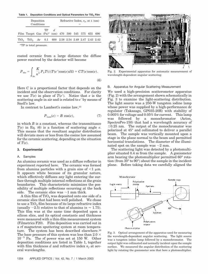
B. Apparatus for Angular Scattering Measurement
We used a high-precision scatterometer apparatus�Fig. 2� with the arrangement shown schematically inFig. 3 to examine the light-scattering distribution.The light source was a 250-W tungsten iodine lampwhose power was supplied by a high-performance dcregulator �Takasago, GP035-20R� with stability of0.005% for voltage and 0.05% for current. This lampwas followed by a monochromator �Acton,SpectroPro-150� that had a wavelength accuracy of�0.25 nm. The output of the monochromator waspolarized at 45° and collimated to deliver a parallelbeam. The sample was vertically mounted upon astage in the plane normal to the beam and permittedhorizontal translations. The diameter of the illumi-nated spot on the sample was �2 mm.
The scattering light was detected by a photomulti-plier situated 0.4 m from the sample. A goniometerarm bearing the photomultiplier permitted 60° rota-tion �from 30° to 90°� about the sample in the incidentplane. Before taking data we carefully aligned the
Fig. 2. Experimental apparatus for automatic measurement ofwavelength-dependent angular scattering.
Fig. 3. Optical arrangement of the apparatus used for measuringthe wavelength-dependent angular scattering. The light sourcewas a tungsten iodine lamp followed by a monochromator. Theoutput light was collimated and normally incident upon the samplesurface. We measured the angular distribution of the scatteringlight by rotating the goniometer arm that bore a photomultiplier.
Table 1. Deposition Conditions and Optical Parameters for TiO2 Film
Film
DepositionConditions
d�nm�
Refractive Index, nf, at � �nm��
Target GasTP
�Pa�a 470 500 545 575 655 690
TiO2 TiO2 Ar 0.1 600 2.58 2.54 2.49 2.47 2.43 2.42
aTP is total pressure.
1354 APPLIED OPTICS � Vol. 42, No. 7 � 1 March 2003
apparatus such that the spot illuminated on the sam-ple coincided with the center of goniometer arm’srotation. The angle of rotation was accurately posi-tioned with a stepping motor �Yokogawa, DM1045B�controlled by a computer to a precision of �15�. Theangular repeatability was �2�. The solid angle ofscattering light for detecting was limited to 5 � 104
sr by the aperture in front of the photomultiplier.This aperture was designed to ensure that only theilluminated spot of the sample was viewed by thedetector and that stray light from other directionswas rejected. The polarization angles for light de-tection were set parallel to that of incidence, namely,at 45°.
Experimental measurements were performed in adust-free darkroom. Before making the measure-ment we heated the system for more than 2 h toachieve the best stability; the effects of spurious lightwere minimized. To do this, we covered all the dis-plays, including the indicating lights of instrumentsin the darkroom, with aluminum foil. Signal fluctu-ations were usually 2.5% during the course of anexperiment. We established the absolute zero of sig-nal by measuring the scattering power of a Spec-tralon standard white diffuser �99% reflectance� at ascattering angle of 90°. We set this signal to zero byadjusting the voltage for the photomultiplier �in thelinear response region�, and this voltage was keptconstant for all measurements.
Our apparatus permitted angle-resolved orwavelength-dependent measurement, or both, of dif-fuse reflectance. That is, at each scattering angle,the scattering can be measured as a function of wave-length. In the experiments reported here the detec-tor was moved from 30° to 90° in incremental steps of5°; at each incremental step the wavelength wasscanned from 450 to 830 nm in 5-nm steps. There-fore we had 13 spectral curves for one sample, and ittook �2.5 h to perform these measurements.
We used the standard white diffuser to check thecalibration of the entire apparatus before each exper-iment. The uncertainty of the measurement wasfound to be 2% when different spots on the samplesurface were measured.
We focused our attention on the changes in scat-tering distributions of coated and uncoated ceramics.In other words, we stressed the effect of T��� on mod-ification of the curve shape of the cosine law �see Eq.�6��. Inasmuch as we did not intend to make com-parisons of different samples or at different wave-lengths, the measured data were raw signals andwere not referenced to any standards, unless other-wise stated.
4. Experimental Results
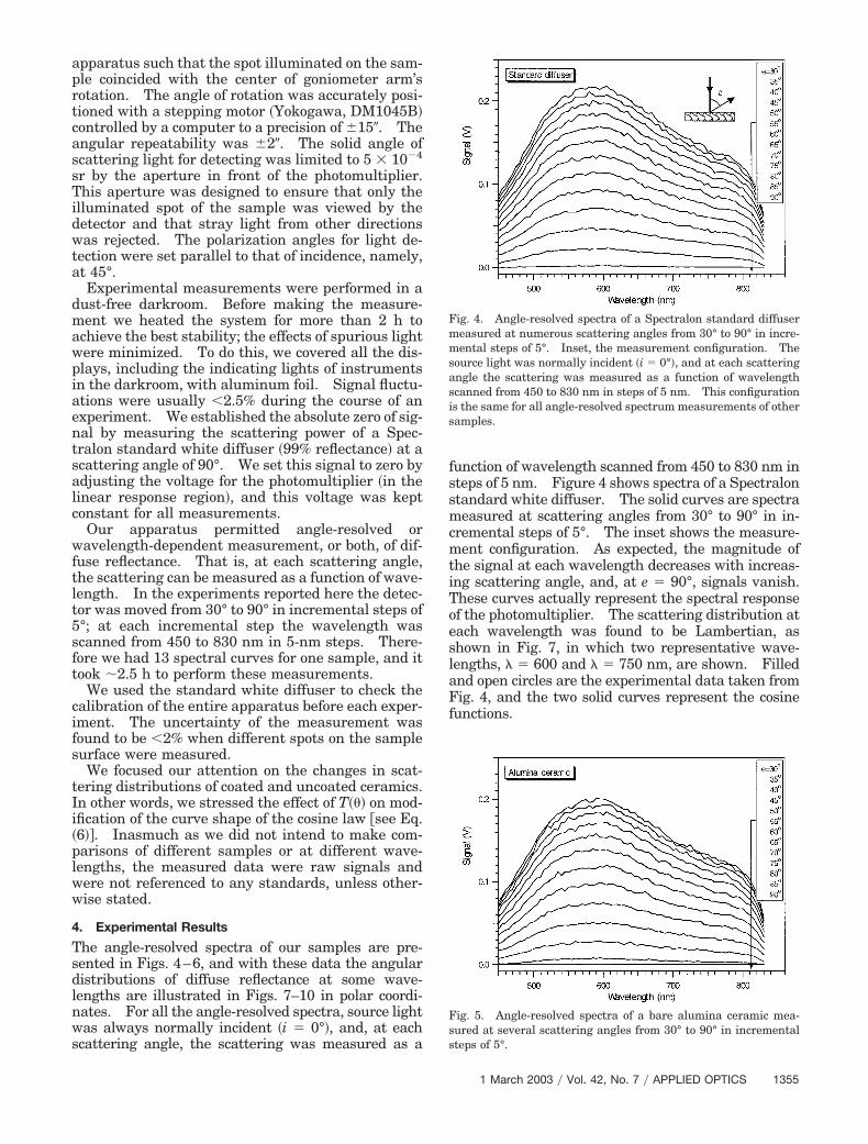
The angle-resolved spectra of our samples are pre-sented in Figs. 4–6, and with these data the angulardistributions of diffuse reflectance at some wave-lengths are illustrated in Figs. 7–10 in polar coordi-nates. For all the angle-resolved spectra, source lightwas always normally incident �i � 0°�, and, at eachscattering angle, the scattering was measured as a
function of wavelength scanned from 450 to 830 nm insteps of 5 nm. Figure 4 shows spectra of a Spectralonstandard white diffuser. The solid curves are spectrameasured at scattering angles from 30° to 90° in in-cremental steps of 5°. The inset shows the measure-ment configuration. As expected, the magnitude ofthe signal at each wavelength decreases with increas-ing scattering angle, and, at e � 90°, signals vanish.These curves actually represent the spectral responseof the photomultiplier. The scattering distribution ateach wavelength was found to be Lambertian, asshown in Fig. 7, in which two representative wave-lengths, � � 600 and � � 750 nm, are shown. Filledand open circles are the experimental data taken fromFig. 4, and the two solid curves represent the cosinefunctions.
Fig. 4. Angle-resolved spectra of a Spectralon standard diffusermeasured at numerous scattering angles from 30° to 90° in incre-mental steps of 5°. Inset, the measurement configuration. Thesource light was normally incident �i � 0°�, and at each scatteringangle the scattering was measured as a function of wavelengthscanned from 450 to 830 nm in steps of 5 nm. This configurationis the same for all angle-resolved spectrum measurements of othersamples.
Fig. 5. Angle-resolved spectra of a bare alumina ceramic mea-sured at several scattering angles from 30° to 90° in incrementalsteps of 5°.
1 March 2003 � Vol. 42, No. 7 � APPLIED OPTICS 1355
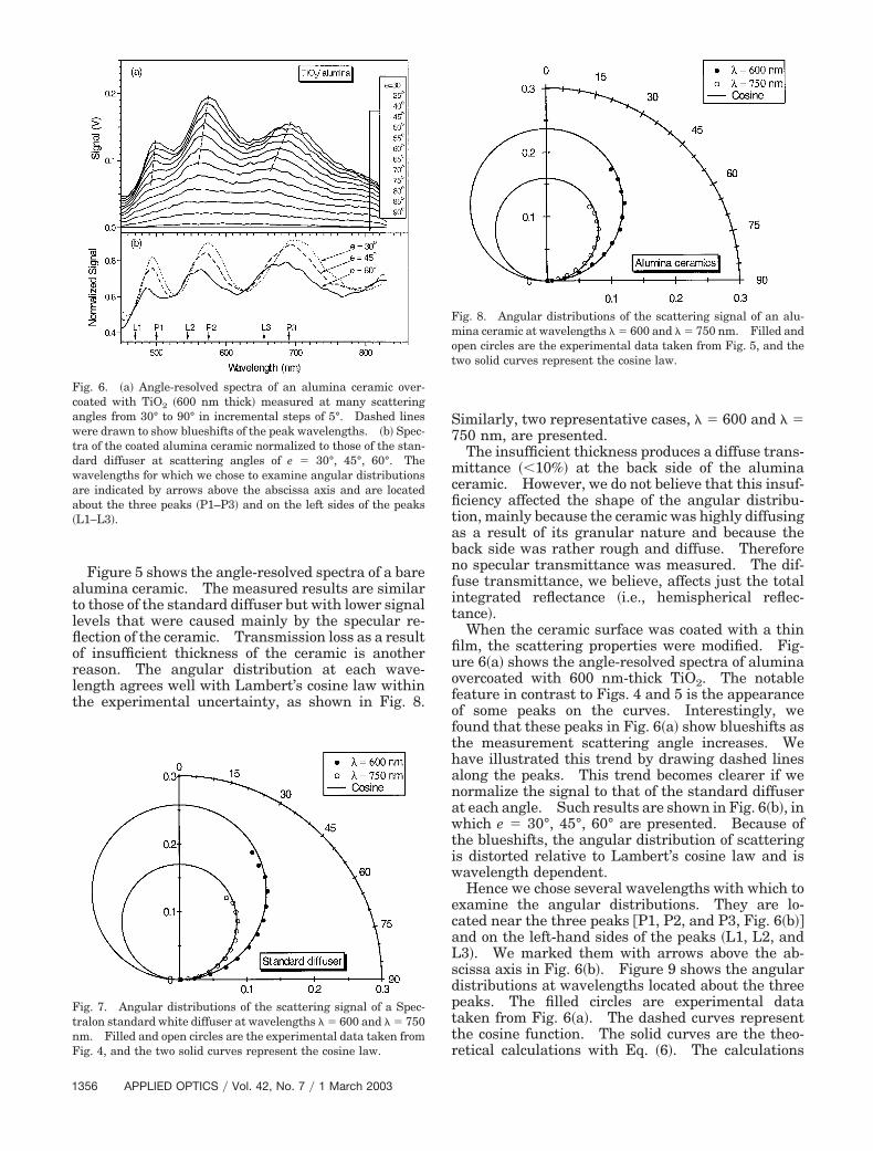
Figure 5 shows the angle-resolved spectra of a barealumina ceramic. The measured results are similarto those of the standard diffuser but with lower signallevels that were caused mainly by the specular re-flection of the ceramic. Transmission loss as a resultof insufficient thickness of the ceramic is anotherreason. The angular distribution at each wave-length agrees well with Lambert’s cosine law withinthe experimental uncertainty, as shown in Fig. 8.
Similarly, two representative cases, � � 600 and � �750 nm, are presented.
The insufficient thickness produces a diffuse trans-mittance � 10%� at the back side of the aluminaceramic. However, we do not believe that this insuf-ficiency affected the shape of the angular distribu-tion, mainly because the ceramic was highly diffusingas a result of its granular nature and because theback side was rather rough and diffuse. Thereforeno specular transmittance was measured. The dif-fuse transmittance, we believe, affects just the totalintegrated reflectance �i.e., hemispherical reflec-tance�.
When the ceramic surface was coated with a thinfilm, the scattering properties were modified. Fig-ure 6�a� shows the angle-resolved spectra of aluminaovercoated with 600 nm-thick TiO2. The notablefeature in contrast to Figs. 4 and 5 is the appearanceof some peaks on the curves. Interestingly, wefound that these peaks in Fig. 6�a� show blueshifts asthe measurement scattering angle increases. Wehave illustrated this trend by drawing dashed linesalong the peaks. This trend becomes clearer if wenormalize the signal to that of the standard diffuserat each angle. Such results are shown in Fig. 6�b�, inwhich e � 30°, 45°, 60° are presented. Because ofthe blueshifts, the angular distribution of scatteringis distorted relative to Lambert’s cosine law and iswavelength dependent.
Hence we chose several wavelengths with which toexamine the angular distributions. They are lo-cated near the three peaks �P1, P2, and P3, Fig. 6�b��and on the left-hand sides of the peaks �L1, L2, andL3�. We marked them with arrows above the ab-scissa axis in Fig. 6�b�. Figure 9 shows the angulardistributions at wavelengths located about the threepeaks. The filled circles are experimental datataken from Fig. 6�a�. The dashed curves representthe cosine function. The solid curves are the theo-retical calculations with Eq. �6�. The calculations
Fig. 6. �a� Angle-resolved spectra of an alumina ceramic over-coated with TiO2 �600 nm thick� measured at many scatteringangles from 30° to 90° in incremental steps of 5°. Dashed lineswere drawn to show blueshifts of the peak wavelengths. �b� Spec-tra of the coated alumina ceramic normalized to those of the stan-dard diffuser at scattering angles of e � 30°, 45°, 60°. Thewavelengths for which we chose to examine angular distributionsare indicated by arrows above the abscissa axis and are locatedabout the three peaks �P1–P3� and on the left sides of the peaks�L1–L3�.
Fig. 7. Angular distributions of the scattering signal of a Spec-tralon standard white diffuser at wavelengths � � 600 and � � 750nm. Filled and open circles are the experimental data taken fromFig. 4, and the two solid curves represent the cosine law.
Fig. 8. Angular distributions of the scattering signal of an alu-mina ceramic at wavelengths � � 600 and � � 750 nm. Filled andopen circles are the experimental data taken from Fig. 5, and thetwo solid curves represent the cosine law.
1356 APPLIED OPTICS � Vol. 42, No. 7 � 1 March 2003
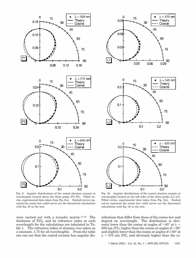
were carried out with a transfer matrix.17,18 Thethickness of TiO2 and its refractive index at eachwavelength for the calculations are tabulated in Ta-ble 1. The refractive index of alumina was taken asa constant, 1.75 for all wavelengths. From the tableone can see that the coated ceramic has angular dis-
tributions that differ from those of the cosine law anddepend on wavelength. The distribution is obvi-ously lower than the cosine at angles of �45° at � �500 nm �P1�, higher than the cosine at angles of 50°and slightly lower than the cosine at angles of �50° at� � 575 nm �P2�, and obviously higher than the co-
Fig. 9. Angular distributions of the coated alumina ceramic atwavelengths located about the three peaks �P1–P3�. Filled cir-cles, experimental data taken from Fig. 6�a�. Dashed curves rep-resent the cosine law; solid curves are the theoretical calculationswith Eq. �6� in the text.
Fig. 10. Angular distributions of the coated alumina ceramic atwavelengths located on the left sides of the three peaks �L1–L3�.Filled circles, experimental data taken from Fig. 6�a�. Dashedcurves represent the cosine law; solid curves are the theoreticalcalculations with Eq. �6� in the text.
1 March 2003 � Vol. 42, No. 7 � APPLIED OPTICS 1357
sine at angles of 50° at � � 690 nm �P3�. As can beseen, these measurements can be well described byour proposed theory, whereas Lambert’s cosine law inthese cases seems unsuitable.
In Fig. 10 the cases when the wavelengths exam-ined were located on the left of the three peaks areshown. Similar distributions can be seen, which aregenerally higher than a cosine. Again, good agree-ment between experiment and theory was obtained.
5. Interpretation of the Measurements
According to our proposed model, the modification inangular distribution results from interference effectsin the thin film. In other words, T�e� in Eq. �6�causes the modification. For scattering light, the in-cident medium is the ceramic and T�e� is given by19
T�e� �t01
2t122
1 � 2r01r12 cos�2� � r012r12
2 , (8)
where t01 and r01 are the Fresnel transmission andreflection coefficients at the ceramic–film interface;they are functions of angle e� �see Fig. 1�. t12 and r12are similar quantities that corresponding to thefilm–air interface; they are functions of �. is thephase difference, given by
�2�nf d cos���
�. (9)
The four Fresnel coefficients can regarded as con-stant because their angles of variance are rathersmall, i.e., 0 e� 35° and 0 � 24° whenscattering angle e varies from 0° to 90° in air. Lightwith larger e� or � will be confined in the film and inthe ceramic and rescattered by the ceramic �this ef-fect was represented by factor K in Eqs. �5� and �6��.Thus, only the term that contains cos�2� in the de-nominator in relation �8� determines the variation ofT�e�, and several results are found.
First, T�e� varies with scattering angle e because eis related to � through Snell’s law. In contrast, Lam-bert’s cosine law requires that T�e� be a constant as evaries �Eq. �7��. Therefore, the measured angulardistributions are distorted �Figs. 9 and 10�, whereasthe standard diffuser and the bare-alumina ceramicconform to the cosine law �Figs. 7 and 8�.
Second, the phase difference in T�e� makes thedistribution dependent on the film’s thickness andrefractive index and on the probe’s wavelength. Inthe present experiments the differences among thedistribution curves �e.g., the three curves in Fig. 9�result mainly from the differences in probe wave-lengths because the TiO2 thin film has weak disper-sion in its refractive index in the wavelength rangethat we measured.
The blueshifts of the peak wavelengths in Fig. 6merely confirm our theory in another way than fromthe angular distribution, which is investigated at afixed wavelength. The blueshifts can be simply in-terpreted with Eq. �9�. According to the interferencetheory, every point on the spectrum corresponds to a
phase difference defined by Eq. �9�. As scatteringangle e increases, the numerator in Eq. �9� decreases�� increases with e�. To keep the phase differenceunchanged, one decreases the denominator, whichleads to a blueshift of the wavelength. However, be-cause the incidence, i.e., specular transmittance T�i��see Eq. �6��, is not always unity but depends on wave-length because of interference effects in the thin film,the blueshifts at different scattering angles becomesomewhat complicated. In other words, we shouldconsider not only T�e�, which is related to the emit-ting conditions, but also T�i�, which is related to theincidence conditions, if we attempt to reproduce thespectrum theoretically. These conditions are allwavelength dependent as far as the spectrum is con-cerned. In this case proportional factor C in Eq. �6�is no longer a constant, and the scattering power canbe given by
Pobs � C�����T�i�T�e�cos�e�, (10)
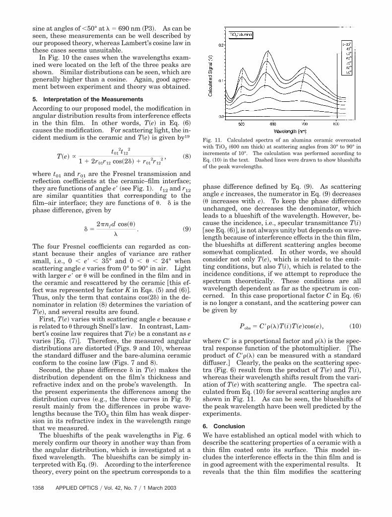
where C� is a proportional factor and ���� is the spec-tral response function of the photomultiplier. �Theproduct of C����� can be measured with a standarddiffuser.� Clearly, the peaks on the scattering spec-tra �Fig. 6� result from the product of T�e� and T�i�,whereas their wavelength shifts result from the vari-ation of T�e� with scattering angle. The spectra cal-culated from Eq. �10� for several scattering angles areshown in Fig. 11. As can be seen, the blueshifts ofthe peak wavelength have been well predicted by theexperiments.
6. Conclusion
We have established an optical model with which todescribe the scattering properties of a ceramic with athin film coated onto its surface. This model in-cludes the interference effects in the thin film and isin good agreement with the experimental results. Itreveals that the thin film modifies the scattering
Fig. 11. Calculated spectra of an alumina ceramic overcoatedwith TiO2 �600 nm thick� at scattering angles from 30° to 90° inincrements of 10°. The calculation was performed according toEq. �10� in the text. Dashed lines were drawn to show blueshiftsof the peak wavelengths.
1358 APPLIED OPTICS � Vol. 42, No. 7 � 1 March 2003
properties of a perfect diffuser; the interference ef-fects in the thin film cause the angular distribution ofthe diffuser to deviate from Lambert’s cosine law.The modification depends on the film’s thickness andrefractive index as well as on the probe wavelength.This effect of the thin film provides us the possibilityof tailoring the scattering properties of a diffuse re-flector as needed, which may be useful for some ap-plications, e.g., in the design of the buffer layer in asolar cell.
References1. S. A. Twomey, C. F. Bohren, and J. L. Mergenthaler, “Reflec-
tance and albedo differences between wet and dry surfaces,”Appl. Opt. 25, 431–437 �1986�.
2. K. C. Jezek and G. Koh, “Effects of water and ice layers on thescattering properties of diffuse reflectors,” Appl. Opt. 26, 5143–5147 �1987�.
3. L. B. Wolff, “Diffuse-reflectance model for smooth dielectricsurfaces,” J. Opt. Soc. Am. A 11, 2956–2968 �1994�.
4. K. R. Catchpole, M. J. McCann, K. J. Weber, and A. W. Blak-ers, “A review of thin-film crystalline silicon for solar cell ap-plications. 2. Foreign substrates,” Sol. Energy Mater. Sol.Cells 68, 173–215 �2001�, and references therein.
5. K. Ishii, H. Nishikawa, T. Takahashi, and Y. Hayashi, “Sub-5micron thin film crystalline silicon solar cell on alumina ce-ramic substrate,” Jpn. J. Appl. Phys. 32, L770–L773 �1993�.
6. T. Takahashi, R. Shimokawa, Y. Matsumoto, K. Ishii, and T.Sekigawa, “Recrystallization of polycrystalline silicon films onceramics by electron beam,” Sol. Energy Mater. Sol. Cells 48,327–333 �1997�.
7. S. Reber, J. Aschaber, and A. Hurrle, “High temperature dif-fusion of iron in PECVD-SiO2 barrier layers for crystallinesilicon thin-film solar cells,” in Second World Conference on PVSolar Energy Conversion, J. Schmid, H. A. Ossenbrink, P.Helm, H. Ehmann, and E. D. Dunlop, eds. �European Commis-sion, Ispra, Italy, 1998�, pp. 1798–1801.
8. R. Shimokawa, K. Ishii, and T. Takahashi, “Optical confine-ment in thin film Si solar cells by diffuse reflective substrate,”Jpn. J. Appl. Phys. 35, 3445–3456 �1996�.
9. K. Winz, Th. Eickhoff, C. Beneking, H. Wagner, C. M. Fort-mann, H. Fujiwara, and I. Shimizu, “Novel light-trappingschemes involving planar junctions and diffuse rear reflectorsfor thin-film silicon-based solar cells,” Sol. Energy Mater. Sol.Cells 49, 195–203 �1997�.
10. J. E. Cotter, “Optical intensity of light in layers of silicon withrear diffuse reflectors,” J. Appl. Phys. 84, 618–624 �1998�.
11. M. Tazawa, K. Yoshimura, K. Igarashi, and S. Tanemura,“Effect of buffer layers on optical confinement in thin film Sisolar cell formed on alumina ceramic substrate,” in SecondWorld Conference on PV Solar Energy Conversion, J. Schmid,H. A. Ossenbrink, P. Helm, H. Ehmann, and E. D. Dunlop, eds.�European Commission, Ispra, Italy, 1998�, pp. 1732–1735.
12. G. Xu, M. Tazawa, P. Jin, and K. Yoshimura, “Optical confine-ment properties of crystalline silicon film on ceramic sub-strate,” Jpn. J. Appl. Phys. 41, 4586–4593 �2002�.
13. M. Tazawa, K. Yoshimura, K. Igarashi, and S. Tanemura,“Optical properties of alumina ceramics as a substrate of thinfilm solar cells,” Sol. Energy Mater. Sol. Cells 48, 315–320�1997�.
14. B. Hapke, Theory of Reflectance and Emittance Spectroscopy�Cambridge U. Press, Cambridge, Mass., 1993�.
15. G. Kortum, Reflectance Spectroscopy �Springer-Verlag, Berlin,1969�.
16. P. Jin and S. Tanemura, “Formation and thermochromism ofVO2 films deposited by RF magnetron sputtering at low sub-strate temperature,” Jpn. J. Appl. Phys. 33, 1478–1483 �1994�.
17. H. S. Hou, “Method for optimized design of dielectric multi-layer filters,” Appl. Opt. 13, 1863–1866 �1974�.
18. B. Harbecke, “Coherent and incoherent reflection and trans-mission of multilayer structures,” Appl. Phys. B 39, 165–170�1986�.
19. O. S. Heavens, Optical Properties of Thin Solid Films �Dover,New York, 1991�.
1 March 2003 � Vol. 42, No. 7 � APPLIED OPTICS 1359


![Dielectric characterization of microwave sintered lead ...cdmf.org.br/wp-content/uploads/2016/11/Goncalves-2016-Dielectric... · ceramics by microwave radiation [12]. Since the first](https://img.pdfslide.net/doc/110x75/5fc1c8c131fd0b11cc286f9d/dielectric-characterization-of-microwave-sintered-lead-cdmforgbrwp-contentuploads201611goncalves-2016-dielectric.jpg)
![Broadband dielectric response of AlN ceramic composites 23 07.pdf · Processing and Application of Ceramics 8 [1] (2014) 47–51 DOI: 10.2298/PAC1401047B Broadband dielectric response](https://img.pdfslide.net/doc/110x75/5fa922ac40e755630c4b9722/broadband-dielectric-response-of-aln-ceramic-23-07pdf-processing-and-application.jpg)


![UNS - Processing and dielectric properties of ZnTiO ceramics … 16 03.pdf · 2012-07-12 · 83 Processing and Application of Ceramics 6 [2] (2012) 83–89 Processing and dielectric](https://img.pdfslide.net/doc/110x75/5ea51469ecc71a45ed171baf/uns-processing-and-dielectric-properties-of-zntio-ceramics-16-03pdf-2012-07-12.jpg)