Embed Size (px)
Citation preview

Objectives_template
file:///C|/Documents%20and%20Settings/iitkrana1/Desktop/new_electroceramics_14may,2012/lecture17a%20(20)/17_1.htm[5/25/2012 12:54:12 PM]
Module 4: Dielectric Ceramics: Basic Principles Introduction
Dielectrics are insulating or non-conducting ceramic materials and are used in many applications suchas capacitors, memories, sensors and actuators. For the sake of simplicity, we can assume that thereis no long range moment of charges. First we will look the simple properties of dielectric materialssuch as dipole moment, polarization, susceptibility, polarizability and polarization mechanisms. Thenwe will do analytical treatment of polarizabilities for each of the polarization mechanisms tounderstand the meaning of these polarizabilities. Subsequently, we will do detailed analysis ofdielectric properties for each of the polarization mechanisms under the influence of alternating field,important from the point of understanding the behaviour of these materials in real conditions. Finally,we will look at the breakdown mechanisms which lead to failure of dielectric materials.
The Module contains
Basic Properties: Dielectrics in DC Electric Field
Summary
Mechanisms of Polarization
Microscopic Approach
Determination of Local Field
Summary
Analytical Treatment of Polarizability
Summary
Effect of Alternating Field on the Behavior of a Dielectric Material
Summary
Frequency Dependence of Dielectric Properties: Resonance
Dipolar Relaxation i.e. Debye Relaxation in Polar Solids
Summary
Circuit Representation of a Dielectric and Impedance Analysis
Impedance Spectroscopy
Dielectric Breakdown
Basic mechanisms of breakdown
Summary
Suggested Reading:
Principles of Electronic Ceramics, by L. L. Hench and J. K. West, Wiley
Dielectrics and Waves, by Arthur R. von Hippel, John Wiley and Sons Inc.

Objectives_template
file:///C|/Documents%20and%20Settings/iitkrana1/Desktop/new_electroceramics_14may,2012/lecture17a%20(20)/17_1.htm[5/25/2012 12:54:12 PM]
Electroceramics: Materials, Properties, Applications, by A. J. Moulson and J.M. Herbert, Wiley
Objectives_template
file:///C|/Documents%20and%20Settings/iitkrana1/Desktop/new_electroceramics_14may,2012/lecture17a%20(20)/17_2.html[5/25/2012 12:54:12 PM]
Module 4: Dielectric Ceramics: Basic Principles
Basic Properties: Dielectrics in DC Electric Field
4.1 Basic Properties: Dielectrics in DC Electric Field
Upon application of a dc or static electric field, there is a long range migration of charges. However,there is a limited movement of charges leading to the formation of charge dipoles and the material,in this state, is considered as polarized. These dipoles are aligned in the direction of the appliedfield.The applied field can also align the dipoles that were already present in the material i.e. materialcontaining dipoles without application of the field.
Of course, both these effects may be present in a single material i.e. dipoles can be aligned as wellas be induced by the applied field.
The net effect is called Polarization of the material.
Objectives_template
file:///C|/Documents%20and%20Settings/iitkrana1/Desktop/new_electroceramics_14may,2012/lecture17a%20(20)/17_3.html[5/25/2012 12:54:13 PM]
Module 4: Dielectric Ceramics: Basic Principles Basic Properties: Dielectrics in DC Electric Field
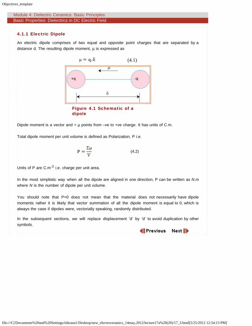
4.1.1 Electric Dipole
An electric dipole comprises of two equal and opposite point charges that are separated by adistance d. The resulting dipole moment, µ is expressed as
(4.1)
Figure 4.1 Schematic of adipole
Dipole moment is a vector and + µ points from –ve to +ve charge. It has units of C.m.
Total dipole moment per unit volume is defined as Polarization, P i.e.
(4.2)
Units of P are C.m-2 i.e. charge per unit area.
In the most simplistic way when all the dipole are aligned in one direction, P can be written as N.mwhere N is the number of dipole per unit volume.
You should note that P=0 does not mean that the material does not necessarily have dipolemoments rather it is likely that vector summation of all the dipole moment is equal to 0, which isalways the case if dipoles were, vectorially speaking, randomly distributed.
In the subsequent sections, we will replace displacement 'd' by 'd' to avoid duplication by othersymbols.

Objectives_template
file:///C|/Documents%20and%20Settings/iitkrana1/Desktop/new_electroceramics_14may,2012/lecture17a%20(20)/17_4.htm[5/25/2012 12:54:13 PM]
Module 4: Dielectric Ceramics: Basic Principles Basic Properties: Dielectrics in DC Electric Field
4.1.2 Polarization and Surface Charge
Figure 4.2 Schematic of a dielectric between twoplates
Imagine a parallel plate capacitor with homogeneously distributed polarized material between theplates.Assume that all the dipole moments are aligned in the same direction. Now, if we look at the chargedensity in a small volume of the material (circle inside the capacitor), then it is clearly zero sinceboth positive and negative charges are equal.
While at the surface, there is a finite charge as shown by the small circle. On both surfaces, thecharges move out by a tiny distance, dx, which is nothing but surface polarization charge which canbe calculated.
The number of charges, nc, on the surface area A is equal to the number of dipoles contained within
a surface volume (V=A.dx) times the charge of the dipole, q which is nothing but equivalent to onelayer of the surface charge.
Assuming homogeneous distribution of the dipoles, polarization can be written as
where the subscript ‘s’ implies the surface. Hence
(4.3)
where ∑s implies sum over the surface volume. Hence
(4.4)
So the surface charge density s is
Objectives_template
file:///C|/Documents%20and%20Settings/iitkrana1/Desktop/new_electroceramics_14may,2012/lecture17a%20(20)/17_4.htm[5/25/2012 12:54:13 PM]
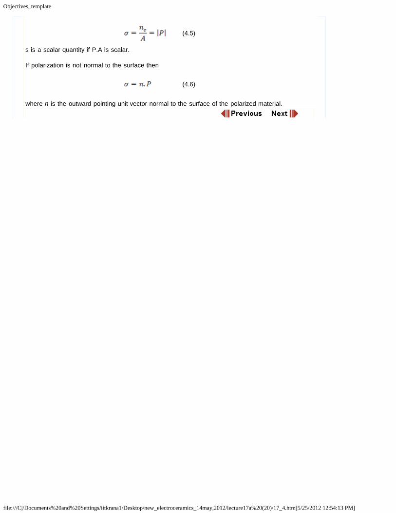
(4.5)
s is a scalar quantity if P.A is scalar.
If polarization is not normal to the surface then
(4.6)
where n is the outward pointing unit vector normal to the surface of the polarized material.

Objectives_template
file:///C|/Documents%20and%20Settings/iitkrana1/Desktop/new_electroceramics_14may,2012/lecture17a%20(20)/17_5.htm[5/25/2012 12:54:13 PM]
Module 4: Dielectric Ceramics: Basic Principles Basic Properties: Dielectrics in DC Electric Field
4.1.3 Dielectric Displacement and Susceptibility
Consider a vacuum plate capacitor configuration as shown below:
Figure 4.3 Parallel plate vacuumcapacitor
Figure 4.4 Parallel plate capacitor with adielectric
For a vacuum capacitor
OR
(4.7)
where capacitance of the vacuum is given as Cvac = (e0A)(d) where eo is the permittivity of free
space and is equal to 8.85x10⁻¹² F/m.
If one inserts a dielectric between plates, then capacitance gets modified as
(4.8)
Where er is dielectric permittivity or more commonly (but not accurately) as relative dielectric
constant with value greater than 1.

Objectives_template
file:///C|/Documents%20and%20Settings/iitkrana1/Desktop/new_electroceramics_14may,2012/lecture17a%20(20)/17_5.htm[5/25/2012 12:54:13 PM]
OR
(4.9)
(4.9)Thus, inserting a dielectric leads to an increase in the stored charge in the capacitor as shownbelow. Basically, er signified some sort of interaction between the material and electromagnetic field.
Figure 4.5 Q-V plot with effect of er
Now the question is: Why does inserting a dielectric increases the capacitance of a capacitor?
We will see this in the following sections.

Objectives_template
file:///C|/Documents%20and%20Settings/iitkrana1/Desktop/new_electroceramics_14may,2012/lecture17a%20(20)/17_6.htm[5/25/2012 12:54:13 PM]
Module 4: Dielectric Ceramics: Basic Principles Basic Properties: Dielectrics in DC Electric Field
4.1.4 Polarization Charges
In a parallel plate capacitor without any dielectric, the surface charge in vacuum ss is
(4.10)
where E is the applied field due to the potential V between the plates.
In the presence of a dielectric, the net charge density now becomes
(4.11)
sexternal is nothing but to due to presence of dielectric and due to polarization of charges and can be
written as spol. Hence,
(4.12)
where ρ is the extra charge resulting from the polarization of the dielectric.
According to the electromagnetic theory, the surface charges on the plates can be defined asdielectric displacement, D, such as
OR
OR
(4.13)
The equation shows that the total charge on the plates of a capacitor with dielectric inserted betweenthe plates is now the sum of the surface charge present in a vacuum capacitor (e0.E) and extra
charge resulting from polarization of the dielectric material, ρ.
Hence, we can now write dielectric displacement as,
(4.14)
OR
(4.15)
where is called dielectric susceptibility and is expressed as
(4.16)

Objectives_template
file:///C|/Documents%20and%20Settings/iitkrana1/Desktop/new_electroceramics_14may,2012/lecture17a%20(20)/17_6.htm[5/25/2012 12:54:13 PM]
This implies that susceptibility is nothing but the ratio of polarized charge or excess charge to thesurface charge in a vacuum capacitor.
Now the question arises: What is the reason for polarization? It can be said that it is basically due toshort range movement of masses i.e. electrons, or atoms or molecules under applied electric field.Such a movement is not likely to occur arbitrarily fast, rather it is a function of the frequency of theapplied field. This also implies that the dielectric properties are also a function of the frequency.These properties are also a function of material structure and temperature. But for now, we will turnour attention to the understanding of basics of mechanisms of polarization and qualitatively what itmeans in terms of applied frequency.

Objectives_template
file:///C|/Documents%20and%20Settings/iitkrana1/Desktop/new_electroceramics_14may,2012/lecture17a%20(20)/17_7.htm[5/25/2012 12:54:14 PM]
Module 4: Dielectric Ceramics: Basic Principles
Summary
Summary
So far, we have learnt that the effect of an applied field on a dielectric material is to polarize it whichis quantified by parameters such as dielectric constant, er ; polarization, P; and dielectric
susceptibility, χ. Next we will learn about the polarization mechanisms and local field inside adielectric.

Objectives_template
file:///C|/Documents%20and%20Settings/iitkrana1/Desktop/new_electroceramics_14may,2012/lecture18a(21)/18_2.htm[5/25/2012 12:54:14 PM]
Module 4: Dielectric Ceramics: Basic Principles Mechanisms of Polarization
4.2 Mechanisms of Polarization
Basically, there are four mechanisms of polarization:
Electronic or Atomic Polarization
This involves the separation of the centre of the electron cloud around an atom with respectto the centre of its nucleus under the application of electric field (see (a) in figure below).
Ionic Polarization
This happens in solids with ionic bonding which automatically have dipoles but which getcancelled due to symmetry of the crystals. Here, external field leads to small displacement ofions from their equilibrium positions and hence inducing a net dipole moment (see (b)).
Dipolar or Orientation Polarization
This is primarily due to orientation of molecular dipoles in the direction of applied field whichwould otherwise be randomly distributed due to thermal randomization (see (c and d)) andfinally
Interface or Space Charge Polarization
This involves limited movement of charges resulting in alignment of charge dipoles underapplied field. This usually happens at the grain boundaries or any other interface such aselectrode-material interface (see (e and f))
.

Objectives_template
file:///C|/Documents%20and%20Settings/iitkrana1/Desktop/new_electroceramics_14may,2012/lecture18a(21)/18_2.htm[5/25/2012 12:54:14 PM]
Figure 4.6 Schematic of mechanisms ofpolarization
Atomic polarization is present in all materials by definition and hence any other mechanismwould be an addition.
While mathematical treatment of the first three mechanisms is rather straightforward, interfacepolarization is not easy to quantify.
Qualitatively, we can see that in the above four mechanisms, the masses of the entities to bedisplaced are different, with mass getting larger from electronic to ionic to dipolarpolarization. This has a direct relation with the frequency of the applied field (see figurebelow). Intuitively, we can mention that heavier the particular entity, more is the time spent indisplacing it. As a result, atomic polarization is the fastest and typically persists at
frequencies between ~1013-1015 Hz. In contrast, ionic polarization is sluggish and typically
occurs at frequencies between ~109-1013 Hz while dipolar polarization involving movement
of molecules happens below 109 Hz. Interface or space charge polarization occurs atfrequencies below 10 Hz.
For non-magnetic dielectrics, Maxwell’s electromagnetic theory predicts that the dielectricconstant obtained from the electronic contribution is also related to the index of refraction as
er = n2 which is true at very high frequencies, above 1012-1013 Hz. Contribution from any
other mechanism will be on top of it. So the total dielectric constant for a material would be
er-electronic (= n2) + er-ionic + er-dipolar.

Objectives_template
file:///C|/Documents%20and%20Settings/iitkrana1/Desktop/new_electroceramics_14may,2012/lecture18a(21)/18_2.htm[5/25/2012 12:54:14 PM]
Figure 4.7 Schematic figures between dielectricconstant vs frequency showing variousmechanisms
The following table shows the values of er and n2 for a variety of materials and the dominant
polarization processes in them:
Material er n2 Dominantmechanisms
C(Diamond)
~5.7 5.85 Electronic
Ge ~16 16.73 Electronic
NaCl ~5.9 2.37 Electronic and Ionic
Water(H2O)
~80 1.77 Electronic, Ionic andDipolar
So, you can see that while carbon and germanium being single elemental materials showelectronic polarization only and as a result their dielectric constants match well with the
values of n2. However, the same is not the case with NaCl or water which have strongcontributions of ionic and ionic and dipolar polarization respectively. We will discuss moreabout these processes in the latter sections.

Objectives_template
file:///C|/Documents%20and%20Settings/iitkrana1/Desktop/new_electroceramics_14may,2012/lecture18a(21)/18_3.htm[5/25/2012 12:54:14 PM]
Module 4: Dielectric Ceramics: Basic Principles Microscopic Approach
4.3 Microscopic Approach
Earlier we saw, polarization in a system with N dipoles per unit volume can be expressed as
i.e.
(4.17)
This gives
(4.18)
Hence, greater is d greater is χ and hence larger is er, i.e. more polarizable a medium is, more is
its dielectric constant.
Further, polarizability of an ion or atom of type, i, in a dipole is defined as
(4.19)
where Eloc is the local electric field experienced by an atom or ion or molecule which can be
different than the applied field. However, magnitude of local field can be modified quite significantlythe polarization of surrounding medium.
As a result P can expressed as
(4.20)
Note that equation (4.20) relates a macroscopic parameter, P, to the microscopic parameters N, aand Eloc.
As a result, in general, susceptibility is
(4.21)
where a is the sum of all types of polarizabilities due to different mechanisms (aelectronic + aionic +
adipolar+ ainterface) as we will see later.
Objectives_template
file:///C|/Documents%20and%20Settings/iitkrana1/Desktop/new_electroceramics_14may,2012/lecture18a(21)/18_4.htm[5/25/2012 12:54:14 PM]
Module 4: Dielectric Ceramics: Basic Principles Determination of Local Field
4.4 Determination of Local Field
The local field, Eloc, experienced by an atom or dipole or molecule usually differs from the applied
field, Eex owing to the polarization of the surrounding medium around a dipole or molecule.
While on a macroscopic scale, the overall field in a material is zero due to the condition of electricalneutrality, when we start looking at the scale of individual atoms and molecules, it is not the case.Although this local field which is nothing but the sum of applied field and some other fields and can,in principle, be solved using Poison’s equation, coupling charge density and potential at eachlocation, the method is far from being simple. Instead, we use a simple approach, by using Lorentzmodel where we divide the field into different components.
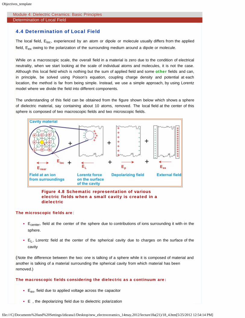
The understanding of this field can be obtained from the figure shown below which shows a sphereof dielectric material, say containing about 10 atoms, removed. The local field at the center of thissphere is composed of two macroscopic fields and two microscopic fields.
Figure 4.8 Schematic representation of variouselectric fields when a small cavity is created in adielectric
The microscopic fields are:
Ecenter, field at the center of the sphere due to contributions of ions surrounding it with-in the
sphere.
EL, Lorentz field at the center of the spherical cavity due to charges on the surface of the
cavity
(Note the difference between the two: one is talking of a sphere while it is composed of material andanother is talking of a material surrounding the spherical cavity from which material has beenremoved.)
The macroscopic fields considering the dielectric as a continuum are:
Eex, field due to applied voltage across the capacitor
E , the depolarizing field due to dielectric polarization
Objectives_template
file:///C|/Documents%20and%20Settings/iitkrana1/Desktop/new_electroceramics_14may,2012/lecture18a(21)/18_4.htm[5/25/2012 12:54:14 PM]
d
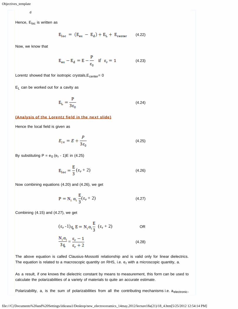
Hence, Eloc is written as
(4.22)
Now, we know that
(4.23)
Lorentz showed that for isotropic crystals,Ecenter= 0
EL can be worked out for a cavity as
(4.24)
(Analysis of the Lorentz field in the next slide)
Hence the local field is given as
(4.25)
By substituting P = e0 (er - 1)E in (4.25)
( + 2) (4.26)
Now combining equations (4.20) and (4.26), we get
( + 2) (4.27)
Combining (4.15) and (4.27), we get
( -1) ( + 2) OR
= (4.28)
The above equation is called Clausius-Mossotti relationship and is valid only for linear dielectrics.The equation is related to a macroscopic quantity on RHS, i.e. er with a microscopic quantity, a.
As a result, if one knows the dielectric constant by means to measurement, this form can be used tocalculate the polarizabilities of a variety of materials to quite an accurate estimate.
Polarizability, a, is the sum of polarizabilities from all the contributing mechanisms i.e. aelectronic,

Objectives_template
file:///C|/Documents%20and%20Settings/iitkrana1/Desktop/new_electroceramics_14may,2012/lecture18a(21)/18_4.htm[5/25/2012 12:54:14 PM]
aionic, adipolar and ainterfacial.
Special case:
For gases
And hence at low pressures
Thus

Objectives_template
file:///C|/Documents%20and%20Settings/iitkrana1/Desktop/new_electroceramics_14may,2012/lecture18a(21)/18_5.htm[5/25/2012 12:54:14 PM]
Module 4: Dielectric Ceramics: Basic Principles Determination of Local Field
4.4.1 Analysis of the Lorentz Field (newly added)
Here, we are interested in calculating the field from the free ends of dipoles i.e. Lorentz field El, linedalong the cavity wall in the direction of applied field, as shown below. This charge density arisesfrom the bound charges and is determined by the normal component of polarization/dielectricdisplacement vector P and is written as
Figure 4.9 Schematic of field components for aspherical cavity
Now, since each element dA contributes to the field, according to Coulomb’s law, the radial fieldintensity is
Each dA’s angular position is between θ and θ+dθ and for each dA element, there is another dAelement on the other side of the sphere which produces same but opposite horizontal fieldcomponent.Horizontal components cancel each other and vertical components dE2 cosθ survives
So the total field intensity is
The field intensity is parallel to the applied field and actually strengthens it. Now we can also rewritedA as
Objectives_template
file:///C|/Documents%20and%20Settings/iitkrana1/Desktop/new_electroceramics_14may,2012/lecture18a(21)/18_5.htm[5/25/2012 12:54:14 PM]
so

Objectives_template
file:///C|/Documents%20and%20Settings/iitkrana1/Desktop/new_electroceramics_14may,2012/lecture18a(21)/18_6.htm[5/25/2012 12:54:15 PM]
Module 4: Dielectric Ceramics: Basic Principles Summary
Summary
Here, we saw that polarization is caused by the movement of electrons or ions or molecules fromtheir equilibrium positions and is frequency dependent. This is because the mass of each entity isdifferent and hence time scales are different. Basically, there are four polarization mechanisms:electronic, ionic, dipolar or orientation and interface and each of these mechanisms is characterizedby different polarizability. The net polarizability of a solid will be sum of these four polarizabilities.
We also learnt that the local field inside a dielectric is not the same as the applied electric field. Thisfield is a result of various microscopic and macroscopic fields inside the dielectric. This leads toderivation of Clausius-Mossotti equation which relates the microscopic dielectric properties to themacroscopic dielectric properties.
Next, we will then calculate the polarizabilities for each polarization mechanisms.
Objectives_template
file:///C|/Documents%20and%20Settings/iitkrana1/Desktop/new_electroceramics_14may,2012/lecture19a(22)/19_2.htm[5/25/2012 12:54:15 PM]
Module 4: Dielectric Ceramics: Basic Principles Analytical Treatment of Polarizability
4.5 Analytical Treatment of Polarizability
Here we discuss the simple analytical solutions for determining the polarizability and polarization foreach of the above polarization mechanisms. The analysis will shed some light on the dependenceof polarizability on the material parameters as well as any external parameters.
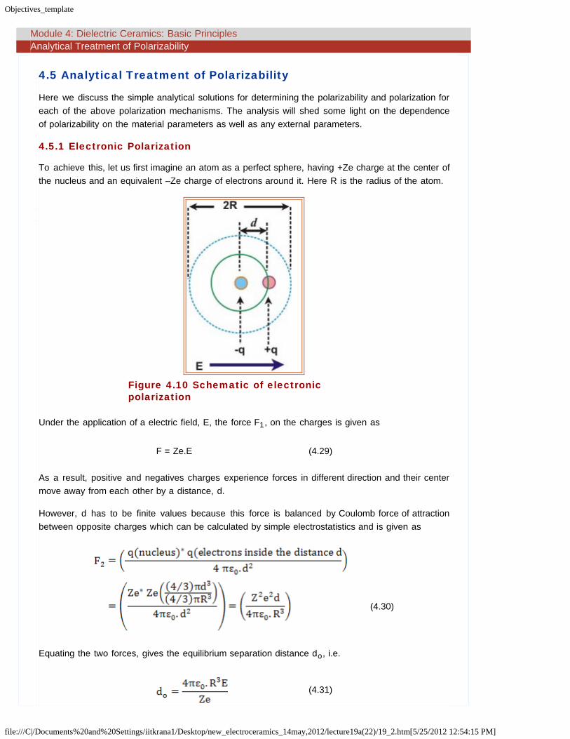
4.5.1 Electronic Polarization
To achieve this, let us first imagine an atom as a perfect sphere, having +Ze charge at the center ofthe nucleus and an equivalent –Ze charge of electrons around it. Here R is the radius of the atom.
Figure 4.10 Schematic of electronicpolarization
Under the application of a electric field, E, the force F1, on the charges is given as
F = Ze.E (4.29)
As a result, positive and negatives charges experience forces in different direction and their centermove away from each other by a distance, d.
However, d has to be finite values because this force is balanced by Coulomb force of attractionbetween opposite charges which can be calculated by simple electrostatistics and is given as
(4.30)
Equating the two forces, gives the equilibrium separation distance do, i.e.
(4.31)

Objectives_template
file:///C|/Documents%20and%20Settings/iitkrana1/Desktop/new_electroceramics_14may,2012/lecture19a(22)/19_2.htm[5/25/2012 12:54:15 PM]
Induced dipole moment, µ, would be
OR
(4.32)
If dipole density was N, the polarization is given as
(4.33)
Using equation (4.15), we can get electronic susceptibility, χe, and electronic polarizability, ae, as
(4.34)
This is a very important result as it allows us to work out the electronic contribution to the dielectricconstant. This also shows the linear relationship between polarization and electric field for electronicpolarization mechanism. Another point to note is that polarizability of atoms with s- and p- atomsi.e. alkali and rate-earth is more than that of transition elements i.e. d-atoms due to higher shieldingof nucleus by electrons in d-atoms.
The equation (4.34) also shows that the larger the atom, the larger is the polarization! Moreover,anions are more polarizable than cations as electrons in anions' outer shells are more looselybound.
The values for atomic polarizability of some atoms are given below:
Halogens Alkali
F 1.2 Li 0.03
Cl 3 Na 0.3
Br 4.5 K 0.9
I 7 Rb 1.7
4.5.1.1 Examples
Assume a typical value for dipole density, N, and atomic radius, R, for a material made up of atoms
with spherical symmetry of orbitals, i.e. N=4*1019 cm and R ˜ 7*10-9 cm, yielding
which is a very small value and the relative dielectric constant,er, does not increase by much.
What it says is that the electronic polarization effect is generally very weak and contributes verylittle to the overall polarization. Having said that, it must be borne in mind that some materials like

Objectives_template
file:///C|/Documents%20and%20Settings/iitkrana1/Desktop/new_electroceramics_14may,2012/lecture19a(22)/19_2.htm[5/25/2012 12:54:15 PM]
Si which are covalently bonded and orbital do not have spherical symmetry and as a result thedielectric constants can be higher (for example Si has about er ~ 12). For electronic polarization, er
is also equal to n2 and hence, if one knows the refractive index, this works as a check for thevalues calculated.
Values for some materials where electronic polarization is the principle mechanism of polarizationare given below (source: "Solid State Physics” by N.W. Ashcroft and N.D. Mermin):
Carbon (diamond) 5.7
Ge 16.0
GaP 8.4
Si 12.0
SiC 6.7
GaAs 10.9

Objectives_template
file:///C|/Documents%20and%20Settings/iitkrana1/Desktop/new_electroceramics_14may,2012/lecture19a(22)/19_3.htm[5/25/2012 12:54:15 PM]
Module 4: Dielectric Ceramics: Basic Principles Analytical Treatment of Polarizability
4.5.2 Ionic Polarization
The figure below shows that in an ionic solid, in the absence of an external electric field, all the
dipoles (formed by each Na+ and Cl- pair with an equilibrium separation distance as do cancel each
other due to crystal symmetry and hence net dipole moment is equal to zero. Remember, in thesesolids, no dipole rotation is allowed.
However, when a finite field, E, is applied, the force experienced by the ions leads them to moveaway from their equilibrium positions , as shown in the figure, giving rise to unequal dipole momentsin different directions and as a result, the material will have net dipole moment.
Figure 4.11 Schematic of the ionicpolarization
As you can now see, the distance between the ions decreases by ‘d’ in one direction and increasesby ‘d’ in the opposite direction.
Now we calculate the magnitude of ‘d’.
The force, F1, which increases the distance between the ions of charge, q, can be expressed as
(4.35)
However, there is a force, F2, in the other direction trying to restore the equilibrium between the
ions which is expressed as
(4.36)
Where ki can be considered as spring constant of the bond between ions assuming ionic dipoles
behave like springs.
The spring constant can be expressed in terms of elastic modulus, Y, and can be expressed as
Objectives_template
file:///C|/Documents%20and%20Settings/iitkrana1/Desktop/new_electroceramics_14may,2012/lecture19a(22)/19_3.htm[5/25/2012 12:54:15 PM]
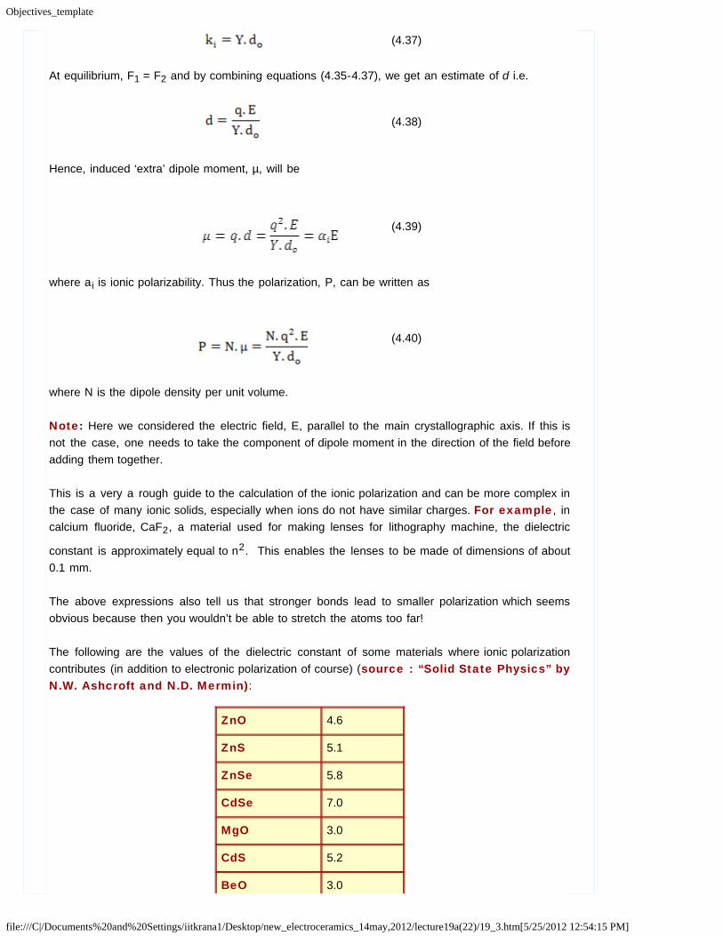
(4.37)
At equilibrium, F1 = F2 and by combining equations (4.35-4.37), we get an estimate of d i.e.
(4.38)
Hence, induced ‘extra’ dipole moment, µ, will be
(4.39)
where ai is ionic polarizability. Thus the polarization, P, can be written as
(4.40)
where N is the dipole density per unit volume.
Note: Here we considered the electric field, E, parallel to the main crystallographic axis. If this isnot the case, one needs to take the component of dipole moment in the direction of the field beforeadding them together.
This is a very a rough guide to the calculation of the ionic polarization and can be more complex inthe case of many ionic solids, especially when ions do not have similar charges. For example, incalcium fluoride, CaF2, a material used for making lenses for lithography machine, the dielectric
constant is approximately equal to n2. This enables the lenses to be made of dimensions of about0.1 mm.
The above expressions also tell us that stronger bonds lead to smaller polarization which seemsobvious because then you wouldn’t be able to stretch the atoms too far!
The following are the values of the dielectric constant of some materials where ionic polarizationcontributes (in addition to electronic polarization of course) (source : “Solid State Physics” byN.W. Ashcroft and N.D. Mermin):
ZnO 4.6
ZnS 5.1
ZnSe 5.8
CdSe 7.0
MgO 3.0
CdS 5.2
BeO 3.0

Objectives_template
file:///C|/Documents%20and%20Settings/iitkrana1/Desktop/new_electroceramics_14may,2012/lecture19a(22)/19_3.htm[5/25/2012 12:54:15 PM]

Objectives_template
file:///C|/Documents%20and%20Settings/iitkrana1/Desktop/new_electroceramics_14may,2012/lecture20(23)/20_2.htm[5/25/2012 12:54:16 PM]
Module 4: Dielectric Ceramics: Basic Principles Analytical Treatment of Polarizability
4.5.3 Dipolar or Orientation Polarization
In case of dipolar polarization, we have materials where the dipoles are present independent ofeach other, i.e. they don’t interact and they can be rotated freely by an applied field unlike in caseof ionic polarization.
One such example is water where each H2O molecule has a dipole moment and these dipole
moments are free to rotate and can have any orientation with respect to neighbouring molecules.Due to the ability of molecules to move around randomly, liquids like water have very limited dipolarpolarization contribution despite having a permanent dipole moment for each molecule.
A two dimensional image of water molecules is shown below which should remain almost similar atany instant. Arrows depict the direction of dipole moment associated with each molecule.
Figure 4.12 Dipoles in a polarmaterial
It is quite obvious by looking at the figure that in the absence of an applied field, all the momentsare randomly distributed (huge number for even a small amount of water, say 10 ml) and net dipolemoment would be zero.
Now when we apply an external electric field say parallel to the paper along +X- axis as shownbelow, the dipoles would tend to align with the applied field to lower their electrostatic energy andlead to minimum dipole energy (basically the positive end of the dipole would like to join thenegative end of the applied field).
For instance, water does have a pretty large dielectric constant of ~80 which means that there isobviously some orientation along the field.
Exercise
You can show it to yourself that this dielectric constant is several orders of magnitude smaller thanfor fully oriented dipole moments at some normal field strengths (see here for solution). In reality, the tendency of dipoles to orient along into the field direction will be counteracted by

Objectives_template
file:///C|/Documents%20and%20Settings/iitkrana1/Desktop/new_electroceramics_14may,2012/lecture20(23)/20_2.htm[5/25/2012 12:54:16 PM]
random collisions between molecules, a process driven by the thermal energy ‘kT’ at a temperature‘T’. Moreover, the dipole containing molecules move around at all times due to thermal energy andthe associated entropy i.e. disorder.
So, basically when we apply an external field, there is a competition between field induced orderand thermal driven disorder. The Later prevails in liquids more than in solids. Hence, perfectalignment of dipoles would be possible only at very low temperature and possibly in solid crystals.
As a result of intermolecular collisions and thermally induced random movement, the dipoles do notcompletely align themselves along the field unless the field is extremely high. So basically, theconfiguration of dipoles looks something like shown below.
Figure 4.13 Effect of electric field on thedipole orientation
This basically highlights that the orientation of all the dipoles is just a little bit shifted towards thefield direction leading to an average non-zero dipole moment in the direction of the applied electricfield.
Thermodynamically speaking, we will minimize the free energy, G which is equal to H – TS whereH is the internal energy and S is the entropy. So for this, now we take the following configurationwhere the charge dipole of an molecule makes an angle, θ, to the applied field.
Figure 4.14 2-D schematic diagram of acharge dipole aligned with respect to appliedfield
The internal energy, U, of a dipole depends on its orientation with respect to the applied field, i.e. itis function of θ.
U is minimum when the dipole is completely aligned with the field i.e.θ = 0 and maximum if θ =
180o.

Objectives_template
file:///C|/Documents%20and%20Settings/iitkrana1/Desktop/new_electroceramics_14may,2012/lecture20(23)/20_2.htm[5/25/2012 12:54:16 PM]
The energy U(θ) of a dipole with dipole moment, µ under an applied field, E, can be written as
(4.41)
What it means in 3-D world is that we would have a cone of dipoles making an angle θ around theapplied field E which points along the axis of the cone as shown below. The total internal energy ofthe whole material would be the sum of internal energies of all these cones.
Figure 4.15 Schematicrepresentation of dipoles around theelectric field
Now we need to calculate the number of dipoles at an angle θ, N(θ) which can then be multipliedwith the energy for that θ and then be integrated between θ ranging from 0 to 180° to give us thetotal internal energy. However, to calculate the free energy, we also need to calculate the entropy,S, which is not very straightforward. This is where Boltzman statistics (from classical thermodynamics) rescues us which allows us towork out the minimum of the free energy using a distribution function.
We treat our system, to a good approximation, as a classical system containing a number ofindependent entities (the dipoles), occupying various energies as determined by their angle w.r.t.applied field. The distribution of these dipoles at various energies can be expressed by a distributionfunction in such a manner that it minimizes the free energy of the system.
Now, at a given temperature, T, the number of dipoles with energy U can expressed as
(4.42)
where A is a constant and kB is Boltzmann constant.
Equation (4.42) provides us the number of dipoles in a cone as shown above.
Now, we should calculate the component of the dipole moment parallel to the applied field using thesolid angle dO for a unit sphere in the segment between θ and θ + dθ.

Objectives_template
file:///C|/Documents%20and%20Settings/iitkrana1/Desktop/new_electroceramics_14may,2012/lecture20(23)/20_2.htm[5/25/2012 12:54:16 PM]
Figure 4.16 Spherical representation ofdipoles
This implies that the number of dipoles between θ and θ + dθ is equal to N(U( θ)).d θ.
The total dipole moment is nothing but the sum of the components of the dipole moments indirection of applied field i.e.
(4.43)
The average dipole moment, <µE>, is calculated by adding up the contributions from all the solid
angles i.e.
(4.44)
The incremental solid can be expressed as
(4.45)
which together with (4.42) yields
(4.46)
To solve this equation, we make substitutions as ß = (µE/kBT) and x = cos θ in the above equation
which yields
(4.47)
or rather
(4.48)

Objectives_template
file:///C|/Documents%20and%20Settings/iitkrana1/Desktop/new_electroceramics_14may,2012/lecture20(23)/20_2.htm[5/25/2012 12:54:16 PM]
where L(ß) = Langevin function, named after Paul Langevin, and is defined as
(4.49)
The function cot h(x) is nothing but (ex + e-x) / (ex - e-x). We won’t go into details of L(x) exceptthat it is not an easy function to deal with and L(x) values are between 0 and 1 for our purposes.
Langevin function is plotted as shown below.
Figure 4.17 Schematic plot of Langevinfunction
As we can see, for large values of ß (i.e. large electric fields or very low temperatures, close to 0K),
(4.50)
while for small values of (ß< 1) i.e. nominal fields and higher temperatures, the slope is 1/3 for ß →0 and hence the Langevin function is approximated by
(4.51)
In general, ß is always much smaller than one i.e.ß << 1.
As a result, the induced dipole moment, often called as Langevin - Debye equation is given as
(4.52)
Where ad is dipolar polarizability. Now, the average polarization is
(4.53)
These equations hold pretty well for small values of µ and E and/or large enough T which we canpresume as normal conditions.
In fact when fields are very high and temperature is very low (i.e. minimizing the randomization), all

Objectives_template
file:///C|/Documents%20and%20Settings/iitkrana1/Desktop/new_electroceramics_14may,2012/lecture20(23)/20_2.htm[5/25/2012 12:54:16 PM]
the dipoles would be parallel to the applied field and then the average dipole moment would beequal to the theoretical dipole moment.
Equation (4.52) also shows the temperature dependence of dipolar polarizability as µ = a, unlike inthe case of electronic and ionic polarization.

Objectives_template
file:///C|/Documents%20and%20Settings/iitkrana1/Desktop/new_electroceramics_14may,2012/lecture20(23)/20_3.htm[5/25/2012 12:54:16 PM]
Module 4: Dielectric Ceramics: Basic Principles Analytical Treatment of Polarizability
4.5.3.1 Example
Suppose for a system
E = 100 MV/cm
µ = 10–29 cm (large enough dipole moment for a strongly polarized molecule, e.g. HCl, andT = 300 K.
Using the above equation, we can calculate ß = 0.24 which validates our analysis.
However, at T = 30 K, ß = 2.4 and this may raise doubts about our analysis.
But, at this temperature it is likely to have liquid into solid state and what we see now is only theeffect of ionic polarization and no longer at orientation polarization!
Similar analysis is applied to the study of magnetic dipoles (a misnomer) in response to a magneticfield.
Unlike our assumption in the beginning, if there is a dipole-dipole strong interaction, such as inmost solids, the dipoles are not free to orient themselves and mostly the contribution in such casesarises from ionic polarization. There are, however, some solids like ferroelectrics where dipoles dointeract and can rotate to some extent giving rise to extraordinary effects as we will study later.

Objectives_template
file:///C|/Documents%20and%20Settings/iitkrana1/Desktop/new_electroceramics_14may,2012/lecture20(23)/20_4.htm[5/25/2012 12:54:16 PM]
Module 4: Dielectric Ceramics: Basic Principles
Summary
Summary
Here, we calculated the electronic and ionic polarizability and the polarizations of the dielectric usingelectronic charge dipoles and ionic lattice having charges coupled as springs. In case of electronicpolarizability, we see that the larger the ion is, the higher is the polarizability. On the other hand,ionic polarizability is inversely proportional to the elastic modulus which is related to the bondstrength. Hence, the higher the bond strength is, the lower is the ionic polarization. Finally wecalculated the dipolar polarization using random dipole model and Boltzman statistics. Here, we sawthat polarizability is inversely related to the temperature which explains the drop in the polarization ofa polar solid upon increasing the temperature.
Next, we will investigate the behavior of dielectric under alternating fields.
Objectives_template
file:///C|/Documents%20and%20Settings/iitkrana1/Desktop/new_electroceramics_14may,2012/lecture21(24)/21_2.htm[5/25/2012 12:54:16 PM]
Module 4: Dielectric Ceramics: Basic Principles Effect of Alternating Field on the Behavior of a Dielectric Material
4.6 Effect of Alternating Field on the Behavior of a DielectricMaterial
Here we will examine the behavior of real and ideal dielectric materials under the influence of analternating electric field, giving an account of the real situations to which dielectric materials aresubjected.
4.6.1 Behavior of an Ideal Dielectric
While most of the above discussion has been for d.c. or static fields, in most practical applications,dielectrics are used under alternating fields. Hence, it is imperative to work out their characteristicsin alternating fields.
Let us apply a sinusoidal field
(4.54)
This leads to the development of a charging current, Ic, due to a change in the charge with time
which is
(4.55)
(4.56)
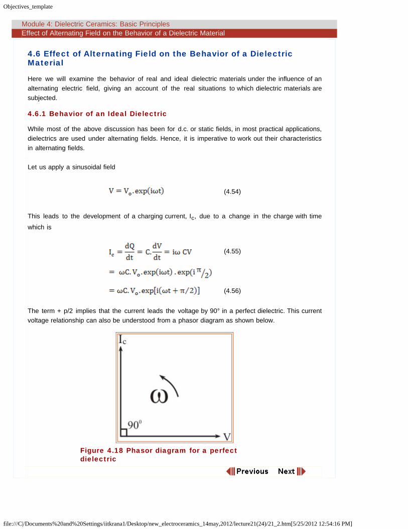
The term + p/2 implies that the current leads the voltage by 90° in a perfect dielectric. This currentvoltage relationship can also be understood from a phasor diagram as shown below.
Figure 4.18 Phasor diagram for a perfectdielectric
Objectives_template
file:///C|/Documents%20and%20Settings/iitkrana1/Desktop/new_electroceramics_14may,2012/lecture21(24)/21_3.htm[5/25/2012 12:54:16 PM]
Module 4: Dielectric Ceramics: Basic Principles Effect of Alternating Field on the Behavior of a Dielectric Material
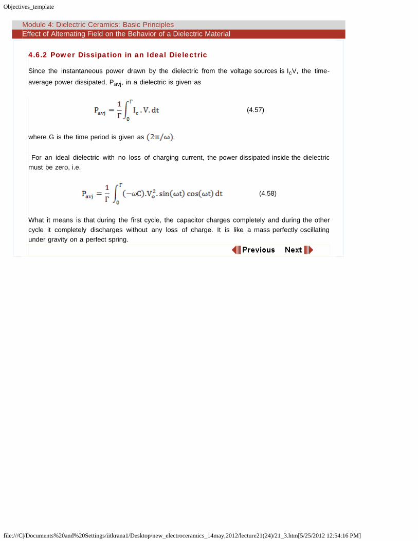
4.6.2 Power Dissipation in an Ideal Dielectric
Since the instantaneous power drawn by the dielectric from the voltage sources is IcV, the time-
average power dissipated, Pavj, in a dielectric is given as
(4.57)
where G is the time period is given as .
For an ideal dielectric with no loss of charging current, the power dissipated inside the dielectricmust be zero, i.e.
(4.58)
What it means is that during the first cycle, the capacitor charges completely and during the othercycle it completely discharges without any loss of charge. It is like a mass perfectly oscillatingunder gravity on a perfect spring.

Objectives_template
file:///C|/Documents%20and%20Settings/iitkrana1/Desktop/new_electroceramics_14may,2012/lecture21(24)/21_4.htm[5/25/2012 12:54:17 PM]
Module 4: Dielectric Ceramics: Basic Principles Effect of Alternating Field on the Behavior of a Dielectric Material
4.6.3 Behavior of Real Dielectrics
However, in real dielectrics, the charging current is also accompanied by a loss current, associatedwith storage of electric charge by the dipoles. There are two sources of this loss current:
Long range migration of charges due to ohmic conduction and is frequency independent i.e.d.c. in nature, and
Dissipation of energy due to dipole rotation or oscillation as there always is certain inertial totheir movement due their mass. This contribution is time-dependent i.e. frequency dependent.
Since, both of these current are in phase with the applied field, the loss current, Il, can be written as
(4.59)
where G depicts the conductance in mho or Siemens which is nothing but the inverse of resistance.Hence, the total current, Il, is the sum of charging and loss current i.e
(4.60)
Hence, the current in a real dielectric is a complex quantity that leads voltage by angle 90o- d whered is defined as the loss angle or dissipation factor. It is made up of two components that are 90° outof phase with respect to each other and have to be added vectorially as shown below. Naturally, dwill be zero if there was no loss current present.
Figure 4.19 Real and Imaginary part of Iand V
When the field applied is static or d.c. i.e. ω = 0 then
where Gdc = 1/R and R is the ohmic resistance.

Objectives_template
file:///C|/Documents%20and%20Settings/iitkrana1/Desktop/new_electroceramics_14may,2012/lecture21(24)/21_4.htm[5/25/2012 12:54:17 PM]
An alternative way to express the real dielectrics passing both charging and loss current is to usecomplex permittivity.
(4.61)
and
(4.62)
Total current in a dielectric can now be expressed in terms of a single material parameter, k, sincecapacitance and charge are
(4.63)
Using equation (4.54), the total current can be expressed as
(4.64)
i.e.
(4.65)
Here
(4.66)
The first term in (4.65) is the out-of-phase charging current term and last two terms are in-phaseloss current terms.
Comparing equation (4.65) with (4.60) yields overall conductance, G, as
(4.67)
where G(ω)ac = ωk''C0V
Loss tangent, tan d, is expressed as
(4.68)
If Gdc << ωk''C0 then
(4.69)
The values of dielectric constant and loss tangent for selected materials are shown below.

Objectives_template
file:///C|/Documents%20and%20Settings/iitkrana1/Desktop/new_electroceramics_14may,2012/lecture21(24)/21_4.htm[5/25/2012 12:54:17 PM]
Material Dielectric Constant (er') Loss Tangent (tand*10-4)
Alumina 10 5-20
SiO2 3.8 2
BaTiO3 500 150
Nylon 3.1 10
Polycarbonate ~3 10
PVC 3 160

Objectives_template
file:///C|/Documents%20and%20Settings/iitkrana1/Desktop/new_electroceramics_14may,2012/lecture21(24)/21_5.htm[5/25/2012 12:54:17 PM]
Module 4: Dielectric Ceramics: Basic Principles Effect of Alternating Field on the Behavior of a Dielectric Material
4.6.4 Power Dissipation in a Real Dielectric
Hence, a.c. conductivity can be expressed as
(4.70)
If sdc is very small, then
(4.71)
Now, the time average power loss can be expressed as
(4.72)
If Gdc << ωk''C0, then
(4.73)
OR
(4.74)
Hence, if C0 =(e0A/d), C0 = (V0/d) and V = A.d, the dissipated power density in a dielectric would
be
One can now see that for static or d.c. fields, ω = 0, i.e.
(4.75)
and hence,
(4.76)
which is the standard equation for power dissipation in a material under dc fields.

Objectives_template
file:///C|/Documents%20and%20Settings/iitkrana1/Desktop/new_electroceramics_14may,2012/lecture21(24)/21_6.htm[5/25/2012 12:54:17 PM]
Module 4: Dielectric Ceramics: Basic Principles
Summary
Summary
We have investigated the behavior of dielectric materials in alternating electric fields. We see that forideal dielectrics, the current leads the voltage by 90° and power dissipation is equal to zero. On theother hand, in real dielectrics, the current leads voltage by an angle 90° - d where d is the lossangle. This results in real and imaginary parts of the dielectric constant and the ratio of imaginary toreal part is loss tangent, depicting the power loss in a real dielectric.
Next we will look into the frequency dependence of the dielectric properties.
Objectives_template
file:///C|/Documents%20and%20Settings/iitkrana1/Desktop/new_electroceramics_14may,2012/lecture22(25)/22_2.htm[5/25/2012 12:54:17 PM]
Module 4: Dielectric Ceramics: Basic Principles Frequency Dependence of Dielectric Properties: Resonance
4.7 Frequency Dependence of Dielectric Properties: Resonance
As briefly shown in the earlier section, polarization mechanisms have frequency dependence andthat is because of the mass associated with the charge dipoles and hence inherent inertia to
movement. This also means that if the frequency of the field is very high, say above 1015 Hz, nodipole system will be able to follow the field oscillations and in such a situation, no mechanism willcontribute and hence er ~ 1.
However, at frequencies below 1012 Hz, the dielectric properties are affected by the frequency ofthe field.
In case of electronic and ionic polarization, the charge dipoles can be considered behaving asmechanical oscillators where charges are connected with linear springs whose restoring forcebalances the force induced via the applied electric field. The characteristic of any such mechanicallyoscillating system is resonance at a certain frequency.
In case of orientation polarization, there is no direct mechanical restoring force. Instead we havemany statistical events, that respond in their average results to the driving forces of electrical fields.In other words, if a driving force is present, there is an equilibrium state with an (average) net dipolemoment. If the driving force were to disappear suddenly, the ensemble of dipoles will assume anew equilibrium state (random distribution of the dipoles) within some characteristic time calledrelaxation time. This process does not show any resonance phenomena and is characterized by itsrelaxation time instead of a resonance frequency.

Objectives_template
file:///C|/Documents%20and%20Settings/iitkrana1/Desktop/new_electroceramics_14may,2012/lecture22(25)/22_3.htm[5/25/2012 12:54:18 PM]
Module 4: Dielectric Ceramics: Basic Principles Frequency Dependence of Dielectric Properties: Resonance
4.7.1 Description of Ionic and Electronic Phenomenon
If we assume charge dipoles behaving like a linear harmonic oscillator, then they also follow the itsequation of motion.
The equation of motion describing an oscillating system driven by a sinusoidal force can be writtenas
(4.77)
where mi* is the mass of the particle (i.e. charges or ions containing charges), i, x is the
displacement from the equilibrium, γi is the friction coefficient on the species and ω0,i is the natural
frequency of the particle. In this equation, on the left hand side, the first term is the force due toacceleration, the second term is the damping or frictional force, and the third term is the springrestoring force, while the term on the right hand side is the force due to applied electric field.
The field will actually be local field than just the applied field but for the sake of simplicity, we canassume the system to behave like a gas consisting of N atoms per unit volume for which qi = -Zie.
Consider two cases:
Case I: When the applied field in d.c. and is switched off at a given moment
Restoring force pulls back the charges to equilibrium.
If friction is zero, there will be no damping of oscillations.
If friction is present, then system will have damped oscillations.
Case II :
When applied field is sinusoidally varying field i.e.
(4.78)
The corresponding displacement is given as
(4.79)
Ignoring transient terms, the solution of equation (4.78) is
(4.80)
The induced dipole moment per particle is

Objectives_template
file:///C|/Documents%20and%20Settings/iitkrana1/Desktop/new_electroceramics_14may,2012/lecture22(25)/22_3.htm[5/25/2012 12:54:18 PM]
(4.81)
(4.82)
where aiis the electronic or ionic polarizability as be the case. If the friction term is neglected, then
frequency dependent polarizability is
(4.83)
Here mass, mi, is either the mass of electrons in atoms or ions in crystals.
In case of ionic polarization, one takes the reduced mass which is given as {M+ M- / (M++
M-)} where M+ and M- are cation and anion masses respectively. Similarly qi will be charge on the
particle as appropriate and ω0,i will be natural frequency of electronic or ionic polarization
mechanisms.
The polarization can then be written as
(4.84)
Hence using equations (4.15) and (4.16) we get the expressions for the susceptibility and dielectricconstant as
(4.85)
and
(4.86)
Here * implies that these are complex quantities which was also mentioned earlier when wediscussed power dissipation characteristics in real dielectrics.
The subscript 8 signifies the susceptibility and dielectric constants at frequencies below the
resonance frequencies. Resonance for electronic polarization occurs at about 1015 s-1 and for ionic
polarization occurs at about 1013 s-1.
Now, we can separate out the real and imaginary parts of the dielectric constants as following
(4.87)
and

Objectives_template
file:///C|/Documents%20and%20Settings/iitkrana1/Desktop/new_electroceramics_14may,2012/lecture22(25)/22_3.htm[5/25/2012 12:54:18 PM]
(4.88)
These can be plotted vs frequency as shown below.
Figure 4.20 Schematic plot of real and imaginaryparts of dielectric constant for electronic andionic polarization
The value of resonance frequency can be determined from the polarizability expressions we
determined above in equations (4.34) and (4.39) as we know that . All now you need
to do is to balance the force inducing the moment and the restoring force to find out the spring
constant. The value of ω0 works out to be about 1013 Hz for ionic and 1015 Hz for electronic
polarization mechanism. This makes sense because for ionic polarization, the masses of ions are
several thousand times higher than electrons and 1013 Hz is very close to the natural frequency oflattice vibrations!
The shape of the plot should also help you understand the far right portion of the dielectric constantversus frequency plot shown earlier when we discussed mechanisms of polarization. For very
frequencies when ω → 8, er' = 1 or e' = e0.
You must remember that the above discussion is valid for gases with non-interacting dipoles for weassumed that local field was equal to the applied field. If we use the local field instead of the applied
field i.e. Eloc= E/3(er'' + 2), fortunately we don’t change the form of expressions, rather we get only
a shift in the resonance frequency. The changed resonance frequency is .
Naturally for a system with ionic polarization, electronic polarization will be in-built simply becauseanything is made of atoms.
Objectives_template
file:///C|/Documents%20and%20Settings/iitkrana1/Desktop/new_electroceramics_14may,2012/lecture22(25)/22_4.htm[5/25/2012 12:54:18 PM]
Module 4: Dielectric Ceramics: Basic Principles Frequency Dependence of Dielectric Properties: Resonance
4.7.1.1 Electronic polarization vis-à-vis frequency
If ω<< ω0,e the charges oscillate in phase with the applied field and contribute to dielectric constant.
If ω0,e = ω, i.e. frequency is equal to the natural frequency of vibration, then resonance occurs and
er' attains a maximum. The charges are 90° out of phase with the applied field and do not contribute
to er'. We witness a maximum loss i.e. high er
''.
If ω0,e < ω, then in this region field changes its direction too fast compared to the rate at which
electrons can move. Hence, electrons do not respond and no polarization results and er' is equal to
1, i.e. system behaves as if there was no dielectric was present.
4.7.1.2 Ionic polarization vis-à-vis frequency
If ω<< ω0,i , the charges oscillate in phase with the applied field and contribute to dielectric
constant. The total dielectric constant is now er,e+i' i.e. both due to ionic and electronic contributions.
If ω0 < ω i.e. frequency is equal to the natural frequency of vibration, then resonance occurs and er'
attains a maximum. The charges are 90° out of phase with applied field and do not contribute to the
dielectric constant and we witness maximum loss i.e. high er''.
If ω0,i < ω, then in this region field charges its direction too fast compared to the rate at which ions
can move. Hence, ions don’t respond and no ionic polarization results and er' is er,e
', i.e. the system
behaves as if there was no ionic polarization mechanism present.

Objectives_template
file:///C|/Documents%20and%20Settings/iitkrana1/Desktop/new_electroceramics_14may,2012/lecture22(25)/22_5.htm[5/25/2012 12:54:18 PM]
Module 4: Dielectric Ceramics: Basic Principles Frequency Dependence of Dielectric Properties: Resonance
4.7.2 Microscopic Examination of Polarizability
From the equation (4.83), for electronic polarization, we can write the electronic or atomicpolarizability as
(4.89)
Here, we have replaced the subscript i with e for electrons.
We can get an expression for ω0 ( = (k (spring constant)/m (mass))1/2) by equating the restoring
force (k.dx) and the force inducing the displacement. From that the atomic polarizability can beexpressed as
(4.90)
which is nothing but equation (4.34) where we worked out the atomic polarizability just from forcebalance.
A similar analysis can be carried out for ionic polarization as well which is left to you as an exercise.

Objectives_template
file:///C|/Documents%20and%20Settings/iitkrana1/Desktop/new_electroceramics_14may,2012/lecture23(26)/23_2.htm[5/25/2012 12:54:18 PM]
Module 4: Dielectric Ceramics: Basic Principles Dipolar Relaxation i.e. Debye Relaxation in Polar Solids
4.8 Dipolar Relaxation i.e. Debye Relaxation in Polar Solids
Relaxation processes occur in many ceramics and ionic solids, especially glasses and thesematerials applying damped forced oscillator approach does not work in the low frequencyregion.
In such cases, the structure of the solid plays an important role because movement ofcharges may have to occur over many atomic distances and can be classified as diffusionalin nature. These processes can be strongly temperature dependent in nature.
As a result, it may take considerable amount of time in the distribution of charges.
Figure 4.21 Potential energy distribution ofionic sites in a glass
For instance, in an ionic solid, application of a field leads to first almost instantaneousdevelopment of ionic and electronic polarization followed by slow development of dipolarpolarization, Pd to a saturation polarization, Ps.
Figure 4.22 Dependence of dipolar polarization ontime
We can approximately express the rate of change of polarization as
(4.91)
Objectives_template
file:///C|/Documents%20and%20Settings/iitkrana1/Desktop/new_electroceramics_14may,2012/lecture23(26)/23_2.htm[5/25/2012 12:54:18 PM]
where 1/t is the proportionality constant. The above equation is also called RelaxationEquation. This equation can be derived using a simple bi-stable model in a similar fashion tothat used in Module 3 (section 3.10) .

Objectives_template
file:///C|/Documents%20and%20Settings/iitkrana1/Desktop/new_electroceramics_14may,2012/lecture23(26)/23_3.html[5/25/2012 12:54:19 PM]
Module 4: Dielectric Ceramics: Basic Principles Dipolar Relaxation i.e. Debye Relaxation in Polar Solids
4.8.1 Bi-stable model for dipolar relaxation
Figure 4.23 Schematic of a polar molecule going onestate to another and resulting energy well diagram
In a solid when field is applied to a polar material, the ions hop from ionic position to another as
shown above in figure 4.23, e.g. Na+ movement in glasses. We consider a bistable dipole model. Asthe cation moves from left to right, there is a change in the co-ordinates. At any temperature above0K, there is random oscillation of cation between these sites.
The probability of jump between sites is given as
(4.92)
Upon application of field, the wells tilt in the direction of applied field, resulting in unequal probabilityin two directions resulting a net flow of dipoles
(4.93)
where E is the applied field.
Under the application of an ac field, the change in the number of dipoles at site 1 = outflow to site 2– inflow to site 1 i.e.
(4.94)
Where N1 + N2 = N = constant
Further, since
Objectives_template
file:///C|/Documents%20and%20Settings/iitkrana1/Desktop/new_electroceramics_14may,2012/lecture23(26)/23_3.html[5/25/2012 12:54:19 PM]
(4.95)
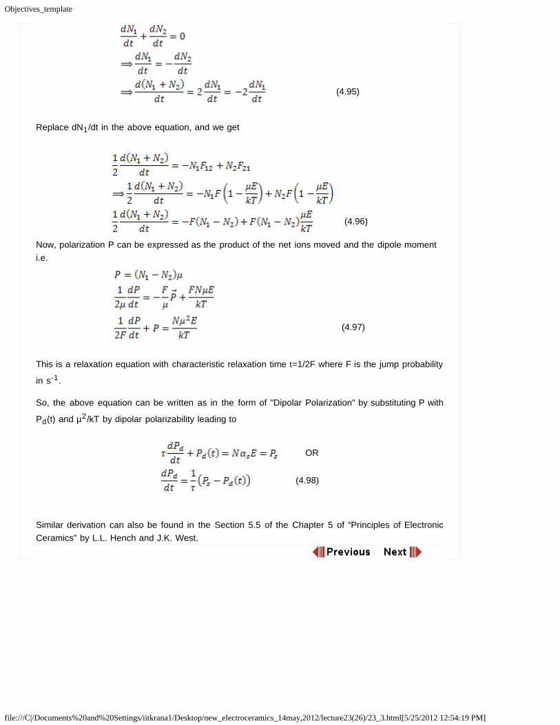
Replace dN1/dt in the above equation, and we get
(4.96)
Now, polarization P can be expressed as the product of the net ions moved and the dipole momenti.e.
(4.97)
This is a relaxation equation with characteristic relaxation time t=1/2F where F is the jump probability
in s-1.
So, the above equation can be written as in the form of "Dipolar Polarization" by substituting P with
Pd(t) and µ2/kT by dipolar polarizability leading to
OR
(4.98)
Similar derivation can also be found in the Section 5.5 of the Chapter 5 of “Principles of ElectronicCeramics” by L.L. Hench and J.K. West.

Objectives_template
file:///C|/Documents%20and%20Settings/iitkrana1/Desktop/new_electroceramics_14may,2012/lecture23(26)/23_4.htm[5/25/2012 12:54:19 PM]
Module 4: Dielectric Ceramics: Basic Principles Dipolar Relaxation i.e. Debye Relaxation in Polar Solids
4.8.2 Solution of relaxation equations
The initial and final conditions are
At t = 0, Pd = 0 and at some reasonably large t, P=Ps
Integrating within these limits yield
(4.99)
where t is defined as relaxation time.
Application of alternating fields to this polarization is not as simple as in the previous analysis
This is because the saturation polarization, Ps, is dependent on the instantaneous value of field and
thus will be time-dependent and the local field is a function of both position and time.
In any case, if we assume that polarizing field is expressed as E* = E0 exp (1wt) then
Ps can be expressed as
(4.100)
Here, we can define ers' as static dielectric constant or dielectric constant at very low frequencies
and er8' is dielectric constant at high frequencies covering electronic and ionic polarization. This
kind of makes sense because dipolar polarization occurs between these two ends of the frequency.
Now, substitute E* and Ps into (4.98)
(4.101)
The integration of this equation yields us
(4.102)
Here the first term is the transient time dependent term depicting decay of the d.c. charges on thecapacitor and second term is the a.c. behavior of the polarization under an alternating field.
Since, electronic and ionic polarization are approximately frequency independent in this regime offrequencies, we can write
(4.103)

Objectives_template
file:///C|/Documents%20and%20Settings/iitkrana1/Desktop/new_electroceramics_14may,2012/lecture23(26)/23_4.htm[5/25/2012 12:54:19 PM]
Now ignoring the transient time dependent term of (4.95) and substituting (4.96) into (4.94), we get
(4.104)
We also know that er* = er' - ier'', hence, now we can separate the real and imaginary parts as
OR
(4.105a)
(4.105b)
and the loss tangent is
(4.106)
The above equations are called Debye equations.
The graphical representation of these is shown below:
Figure 4.24 Graphical representation of Debyeequations
Here, the relaxation frequency is defined as inverse of the relaxation time i.e. 1/t.
The equation (4.98) and the above figure suggest that er' is independent of frequency at values
corresponding to the sum of three polarizations i.e. Pd+Pi+Pe. As the applied field frequency
approaches value ω = 1/t, er' passes an inflection and then drops off to er8' which is dependent
only on (Pi+Pe).
At ω = 1/t, the oscillating charges are coupled with the applied field and absorb maximum energy

Objectives_template
file:///C|/Documents%20and%20Settings/iitkrana1/Desktop/new_electroceramics_14may,2012/lecture23(26)/23_4.htm[5/25/2012 12:54:19 PM]
as depicted by the peak in er'' magnitude of er'' peak being (ers'' - er8')/2 depending upon the
number of oscillating charges and distance of motion.
It is also seen that tand is also goes than a maximum, but at higher frequencies with ω = (ers'/
er8')1/2/t.
Now since, we have understood that polarization develops by temperature dependent diffusionalprocesses which also give rise to the d.c. conductivity, temperature dependence of the relaxationtime, t can be expressed as
(4.107)
where Qa is the activation energy for dipole relaxation and t0 is the intrinsic relaxation time.
Combining Debye equations with (4.99) we can obtain the frequencies (= ωt) at which maxima forer'' as well as tand occur and you will that these frequencies for the maxima change with
temperature because t is temperature dependent. The plots below show this trend for Li2O.2SiO2
glass ceramic.
Figure 4.25 Shift of tand peak in Li2O.2SiO2 glass due toincreasing temperature (Reproduced from Principle ofElectronic Ceramics, L.L. Hench & J.K. West, P206)

Objectives_template
file:///C|/Documents%20and%20Settings/iitkrana1/Desktop/new_electroceramics_14may,2012/lecture23(26)/23_4.htm[5/25/2012 12:54:19 PM]
Figure 4.26 Temperature dependence of the frequencymaxima vs time for Li2O.2SiO2 glass at 500°C (Reproduced from Principle of Electronic Ceramics, L.L.Hench & J.K. West, P207)

Objectives_template
file:///C|/Documents%20and%20Settings/iitkrana1/Desktop/new_electroceramics_14may,2012/lecture23(26)/23_5.html[5/25/2012 12:54:19 PM]
Module 4: Dielectric Ceramics: Basic Principles Dipolar Relaxation i.e. Debye Relaxation in Polar Solids
4.8.3 Complete Picture of Frequency Dependence of the DielectricConstant
So, now we can plot the contributions to the dielectric constant from all the mechanisms.
In case of an ideal dielectric material exhibiting all four basic mechanisms, we would expect thefollowing curve.
Figure 4.27 Complete plot of frequency dependence ofdielectric constant and loss (note that frequency is not toscale)
Although the above plot represents an ideal material, yet the plot gives an idea of what you mightexpect when you measure dielectric constant of a material as a function of frequency.
Although the real plots may look quite different (look for dielectric constant data for electronicceramics in journal publications), you can expect a correlation between the real and imaginary partof the curve i.e. we can still clearly see the absorption peak.
As, mentioned earlier, for a non-magnetic dielectric solid, Maxwell’s electromagnetic equations
predicts that er be equal to n2.

Objectives_template
file:///C|/Documents%20and%20Settings/iitkrana1/Desktop/new_electroceramics_14may,2012/lecture23(26)/23_6.htm[5/25/2012 12:54:19 PM]
Module 4: Dielectric Ceramics: Basic Principles
Summary
Summary
We looked at the frequency dependence of all three polarization mechanisms. For electronic andionic polarizations, we described charges as linear harmonic oscillators and solved the equation ofmotion in an alternating field. We see that for both these mechanisms, there is a characteristicsfrequency, ω0, where resonance occurs and the loss is maximum. These mechanisms contribute
only when the applied frequency is lower than this characteristic frequency. On the other hand, thescenario for dipolar polarization is depicted by Debye relaxation where inflection in the dielectricconstant occurs a frequency ω = 1/t which is accompanied by a maxima in e. This maxima is also afunction of temperature in many dielectric ceramics.
Next, we will see the circuit representation of dielectric materials which is very important for theircharacterization and understanding of various phenomenon.
Objectives_template
file:///C|/Documents%20and%20Settings/iitkrana1/Desktop/new_electroceramics_14may,2012/lecture24(27)/24_2.htm[5/25/2012 12:54:20 PM]
Module 4: Dielectric Ceramics: Basic Principles Circuit Representation of a Dielectric and Impedance Analysis
4.9 Circuit Representation of a Dielectric and Impedance Analysis
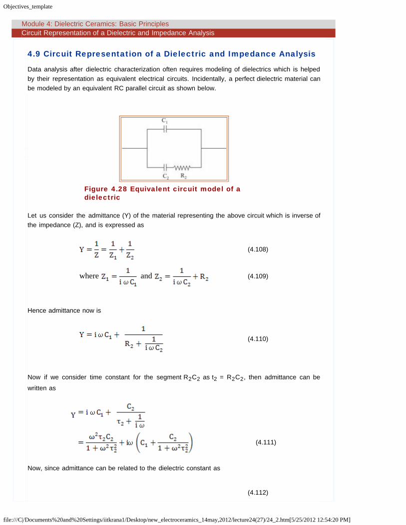
Data analysis after dielectric characterization often requires modeling of dielectrics which is helpedby their representation as equivalent electrical circuits. Incidentally, a perfect dielectric material canbe modeled by an equivalent RC parallel circuit as shown below.
Figure 4.28 Equivalent circuit model of adielectric
Let us consider the admittance (Y) of the material representing the above circuit which is inverse ofthe impedance (Z), and is expressed as
(4.108)
where and (4.109)
Hence admittance now is
(4.110)
Now if we consider time constant for the segment R2C2 as t2 = R2C2, then admittance can be
written as
(4.111)
Now, since admittance can be related to the dielectric constant as
(4.112)

Objectives_template
file:///C|/Documents%20and%20Settings/iitkrana1/Desktop/new_electroceramics_14may,2012/lecture24(27)/24_2.htm[5/25/2012 12:54:20 PM]
This gives
and (4.113)
which have the same form as Debye equations with C2 = (es - e8) C0 and C1 = e8.
In 1941, K.S. Cole and R.H. Cole explained the behavior of dielectrics in alternating fields in whichthey plotted the electrical response of dielectric materials to the alternating fields as a function offrequency. By this technique, they were able to identify and relate the observed relaxation effect with theatomic and microstructural features of the materials.
However, Cole and Cole used modified Debye equation which is
(4.114)
where a is a parameter which describes the distribution of relaxation times in the material.
For an ideal dielectric with well defined relaxation time i.e. a = 0, the system would be representedby the Debye equations i.e. equations (4.104-4.106).
As a result, if we plot er'' (ω) vs er' (ω) i.e. imaginary vs real part of the dielectric constant on a
complex plane, we get a semi-circle.

Objectives_template
file:///C|/Documents%20and%20Settings/iitkrana1/Desktop/new_electroceramics_14may,2012/lecture24(27)/24_3.htm[5/25/2012 12:54:20 PM]
Module 4: Dielectric Ceramics: Basic Principles Impedance Spectroscopy
4.10 Impedance Spectroscopy
The frequency response of the impedance of above circuit would also yields a semi-circle in thecomplex plot between real and imaginary parts of the dielectric constant and such a responserepresent a capacitor with losses. Such technique of characterizing dielectrics is called ImpedanceSpectroscopy.
The intercepts of the semi-circle on the x-axis represent high and low frequency dielectric constantsor er8' and ers' respectively.
The maxima of the semi-circle occurs at
(4.115)
The semicircle equation turns out to be
( - ) + =
which can be obtained by removing ωt from the equations (4.105a) and (4.105b).
Figure 4.29 Cole-ColePlot
Alternatively in a semi-circle one can draw two vectors, X and Y which are always perpendicular toeach other and are related as y = -iωt.xThis relation can easily be obtained just by using theDebye’s equation (4.98) and simple vector additions and subtractions.
Basically any point on the surface of the semi-circle of diameter (ers' - er8' ) in this complex plane
can be defined by these vectors.
In the figure above, a perfect semicircle represents a narrow distribution of relaxation timesindicating only one primary mechanism of polarization.
However, if there is the presence of a tail on the low frequency side, as shown by dashed line i.e.

Objectives_template
file:///C|/Documents%20and%20Settings/iitkrana1/Desktop/new_electroceramics_14may,2012/lecture24(27)/24_3.htm[5/25/2012 12:54:20 PM]
increasing er'' , indicates large distribution of relaxation times and usually is due to high losses in
the material.
In case a material has more than one contribution to the impedance, which is often the case withpolycrystalline ceramics where grain, grain boundaries and electrode-ceramic interface have distinctcontributions, then one can witness more than one semi-circle, often overlapping each other. Anidealized picture of such a scenario can be see below. One of the ways to model such a behaviormay be using three series-parallel RC elements circuit as shown below.
Figure 4.30 Cole-Cole Plot and possible equivalentcircuit for a solid with multiple polarizationmechanisms
Objectives_template
file:///C|/Documents%20and%20Settings/iitkrana1/Desktop/new_electroceramics_14may,2012/lecture24(27)/24_4.htm[5/25/2012 12:54:20 PM]
Module 4: Dielectric Ceramics: Basic Principles Dielectric Breakdown
4.11 Dielectric Breakdown
Every material is bound to fail or breakdown under certain conditions. Basically, in case of adielectric it means short circuiting across the dielectric.
Technically speaking, dielectric breakdown occurs when the electron density in the conduction bandbecomes very high during the application of an electric field such that conductivity increases rapidlyresulting in a permanent damage to material. However, it is easier to measure and talk in terms ofthe electric current which is anyway a representation of electron density.
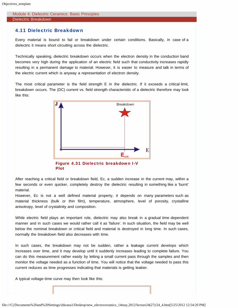
The most critical parameter is the field strength E in the dielectric. If it exceeds a critical limit,breakdown occurs. The (DC) current vs. field strength characteristic of a dielectric therefore may looklike this:
Figure 4.31 Dielectric breakdown I-VPlot
After reaching a critical field or breakdown field, Ec, a sudden increase in the current may, within afew seconds or even quicker, completely destroy the dielectric resulting in something like a ‘burnt’material.However, Ec is not a well defined material property, it depends on many parameters such asmaterial thickness (bulk or thin film), temperature, atmosphere, level of porosity, crystallineanisotropy, level of crystalinity and composition.
While electric field plays an important role, dielectric may also break in a gradual time dependentmanner and in such cases we would rather call it as ‘failure’. In such situation, the field may be wellbelow the nominal breakdown or critical field and material is destroyed in long time. In such cases,normally the breakdown field also decreases with time.
In such cases, the breakdown may not be sudden, rather a leakage current develops whichincreases over time, and it may develop until it suddenly increases leading to complete failure. Youcan do this measurement rather easily by letting a small current pass through the samples and thenmonitor the voltage needed as a function of time. You will notice that the voltage needed to pass thiscurrent reduces as time progresses indicating that materials is getting leakier.
A typical voltage-time curve may then look like this:

Objectives_template
file:///C|/Documents%20and%20Settings/iitkrana1/Desktop/new_electroceramics_14may,2012/lecture24(27)/24_4.htm[5/25/2012 12:54:20 PM]
Figure 4.32 Time dependent failure for adielectric
The values of breakdown fields for some materials are given below:
Material
CriticalFieldStrength[kV/cm]
Oil 200Glass, ceramics 200-400Mica 200-700Oiled paper 1800Polymers 50-900Al2O3 film (100 nm) 16,000
Al2O3 ceramic 200-300
BaTiO3 (bulk single crystal) 300
BaTiO3(Polycrystalline ceramic) 120
SiO2 (in Integrated circuits) > 10,000
Example:
For example, in thin film memory devices, SiO2 is used as a gate dielectric and has a thickness of a
few nanometers say 5 nm. The voltages at which these devices operate are about 5 V whichtranslates into a field of 10 MV/cm which is a very large field when compared to break down fields ofmost of the bulk materials. This explains the importace of material form on the breakdown field.

Objectives_template
file:///C|/Documents%20and%20Settings/iitkrana1/Desktop/new_electroceramics_14may,2012/lecture24(27)/24_5.htm[5/25/2012 12:54:20 PM]
Module 4: Dielectric Ceramics: Basic Principles Basic mechanisms of breakdown
4.12 Basic mechanisms of breakdown
Intrinsic breakdown
Thermal breakdown
Avalanche breakdown
4.12.1 Intrinsic Breakdown
This mechanism is based on lattice ionization and subsequent increase in the electrontemperature.
Actual breakdown field is larger than critical breakdown field, Ec, needed to cause a critical
breakdown electron temperature, Tc.
This mechanism is field dependent and here appliedfield determines the electron temperatureto reach critical level for breakdown
The break time is very short, smaller than ms, suggesting that the process is electronic isnature.
It is independent of sample or its geometry or waveform type.
It is a purely material dependent process.
4.12.2 Thermal Breakdown:
It occurs due to heat dissipation in the sample due to current flowing through defective partsof the sample which in turn further increase the ionic defect concentration leading tosubsequent increase in the conductivity and then failure.
It is a very common process in most of the bulk materials.
It depends on the speed of application of field.
It is observed between room temperature and 300°C.
Ambient temperature determines the electron temperature and not the electric field strength.
Rate of application of field is an important factor.
The process can be quite slow, from minutes to ms, and is dependent on sample geometry
The shorter the pulse time is, the higher is the breakdown voltage.
4.12.3 Avalanche Breakdown
Large electric field in the samples lead to energetic electrons which can further lead to amultiplication process i.e. a few electrons knock out more and more electrons leading to alarge increase in the conductivity.

Objectives_template
file:///C|/Documents%20and%20Settings/iitkrana1/Desktop/new_electroceramics_14may,2012/lecture24(27)/24_5.htm[5/25/2012 12:54:20 PM]
There is a gradual build up of charge rather than sudden change in conductivity even throughcharge build up can be quite fast.
Quite often it occurs in thin films.
It occurs at low temperature and in short time.
Other or Pseudo breakdown mechanisms are
Dielectric discharge
Electrochemical and/or mechanical breakdown
Dielectric discharge
In small pores which are always present in sintered dielectric ceramics, the field strength ishigher than the average field and as a result, microscopic arc discharge in the pores may beinitiated.
Electrons and ions from the discharge bombard the inner surface and erode it. As the poresgrow, the current in the arc increases leading to an increased sample temperature eventuallyleading to failure.
Electrochemical breakdown
This occurs due to transport of conducting material due to the presence of localelectrochemical current paths or defect into the interior of the dielectric leading to overallincrease in the sample conductivity and then failure.
It is assisted by suitable atmospheric conditions such as humidity and pH.
Objectives_template
file:///C|/Documents%20and%20Settings/iitkrana1/Desktop/new_electroceramics_14may,2012/lecture24(27)/24_6.htm[5/25/2012 12:54:20 PM]
Module 4: Dielectric Ceramics: Basic Principles Summary
Summary
A dielectric material is characterized by parameters such as dielectric constant or dielectricpermittivity which is greater than 1. Other parameters which define dielectric beahviour are dielectricsusceptibility and polarization where the former shows the response of a dielectric material uponapplication of electric field. Polarization in dielectrics happens because of variety of reasons and is afrequency dependent phenomenon as characterized by electronic, ionic and dipolar or orientationpolarizations. Application of an alternating field on real dielectrics results in real and imaginary part ofdielectric constant and in a loss tangent which define the quality of a dielectric. Frequencydependence of dielectric constant is also characterized by the presence of resonance phenomenon
for electronic and ionic polarization mechanisms, occurring at frequencies typically above 1012 Hzand relaxation phenomenon for orientation or dipolar polarization in polar materials which is atypically low frequency mechanism. The frequency dependence can also be modeled by impedancespectroscopy and Cole-Cole plots which give an insight into various relaxation mechanisms in adielectric material arising due to various microstructural features.


![Broadband dielectric response of AlN ceramic composites 23 07.pdf · Processing and Application of Ceramics 8 [1] (2014) 47–51 DOI: 10.2298/PAC1401047B Broadband dielectric response](https://img.pdfslide.net/doc/110x75/5fa922ac40e755630c4b9722/broadband-dielectric-response-of-aln-ceramic-23-07pdf-processing-and-application.jpg)