Embed Size (px)
Citation preview
Indoor/Outdoor 2.4GHz
Digital AV Sender -
Control PTZ wirelessly
Manual
V1.2
Please note the PTZ camera, DVR, TV and RS485 Keyboard are
for demo purpose, not included inside the package
WL24
1-512-756-1678

1
Important-Safety PrecautionsTo prevent fire or shock hazard, do not expose this device to rain or moisture. Does not use near a
bathtub, washbowl, kitchen sink, or laundry tub, in a wet basement, or near a swimming pool
1.To avoid electrical shock, do not open this device.
2.This device should be operated to use only the power supply included with it or provided
as an accessory.
3.Do not overload wall outlets and extension cords as this can result in the risk of fire or
electrical shock.
4.Do not attempt to service this device yourself. Refer servicing to qualified personnel only.
5.Reorient or relocate the receiving antenna.
6.Increase the separation between the equipment and receiver.
7.Connect the equipment into an outlet on a circuit different from that to which the receiver
is connected.
8.Consult the dealer or an experienced radio/TV technician for help.
■ Note:
This device complies with Part 15 of the FCC Rules. Operation is subject to the following two
conditions: (1) this device may not cause harmful interference, and (2) this device must accept
any interference received, including interference that may cause undesired operation.
Notice : The changes or modifications not expressly approved by the party responsible
for compliance could void the user’s authority to operate the equipment.
IMPORTANT NOTE: To comply with the FCC RF exposure compliance requirements, the antenna(s)
used for this transmitter must be installed to provide a separation distance of at
least 20 cm from all persons and must not be co-located or operating in conjunction
with any other antenna or transmitter. No change to the antenna or the device is
permitted. Any change to the antenna or the device could result in the device
exceeding the RF exposure requirements and void user’s authority to operate the
device.
12
Video Output Level 1 ± 0.2V p-p @ 75 ohm
Audio Output Level 1 ± 0.2V p-p @ 600 ohm (STEREO)
RS485 port – control Pelco D or Pelco P protocol PTZ camera
Baudrate – 9600/4800/2400/1200bpsby DIP switch
Antenna– omni antenna 3dBi
PA Output Power – 100mW,optional 200mW
Power consumption 1.9W
Power supply 12V/1A
Dimension 76mm x73mm
x 24mm
Weight 82g
System:Transmission channels 26
channels auto selection
Video bit rate up to 12 Mbps
Random ID code up to 4 million sets
Video resolution 720 x 480 @ 30 fps (NTSC) or 768 x 576 @25 fps (PAL)
PTZ camera control wirelessly -
Pelco D or Pelco P auto
detect
Baud rate – 9600/4800/2400/1200 bps
Operational range up to 150meters or 250 meters (line of sight and open site)
●All specification subject to change without notice
(indoor),140mmx180mmx40mm(outdoor)
(indoor),430g(outdoor)
11
Make sure power plugs are pushed all the way in
Check power switches on the remote TV or DVR and Video
source(Camera, Camcorder, etc.)
Check if the POWER LED of the transmitter and receiver is lighting or
not? Their LINK LED should be lit.
If The LINK LED is lit, you must re-pair their codes following the D.
instruction of the manual
Interference: picture
or audio
Adjust receiver and transmitter antenna orientation
Try to place transmitter and receiver a little more close together
The transmission path between the pair may be overlapped by another pair, try to install into a higher
position or separate these two pairs
Trouble shoot by turning off any high power wireless units that are
near by TX or RX, please find it and move or un plug from power.
Transmitter:Operating Frequency Band 2.400GHz~2.483GHz
Modulation 16QAM/QPSK/BPSK
Video Input Level 1V p-p @
75 ohm
Audio Input Level 1V p-p @
600 ohm (STEREO)
RS485 port – control Pelco D or Pelco P protocol PTZ camera
Baud
rate –
9600/4800/2400/1200bpsby DIP switch
Antenna
–
omni antenna
3dBi
PA Output Power –
100 Mw,optional 200mW
Power consumption 1.9W
Power supply 12V/1A
Dimension 76mm x
73mmx 24mm(indoor),140mmx180mmx40mm(outdoor)
Weight 82g(indoor),430g(outdoor)
Receiver:Operating Frequency Band 2.400GHz~2.483GHz
Modulation 16QAM/QPSK/BPSK
Receiver Sensitivity -85dBm min.
2
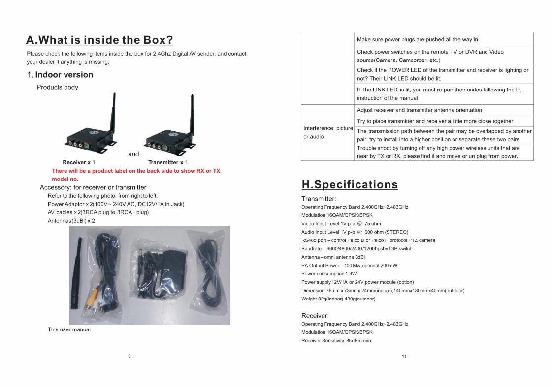
Please check the following items inside the box for 2.4Ghz Digital AV sender, and contact
your dealer if anything is missing:
1. Indoor version
Products body
and Receiver x 1 Transmitter x 1
There will be a product label on the back side to show RX or TX
model no.
Accessory: for receiver or transmitter Refer to the following photo, from right to left: Power Adaptor x 2(100V ~ 240V AC, DC 12V/1A in Jack)
AV cables x 2(3RCA plug to 3RCA plug)
Antennas(3dBi) x 2
This user manual
A.What is inside the Box?
H.Specifications
or 24V power module (option)
10
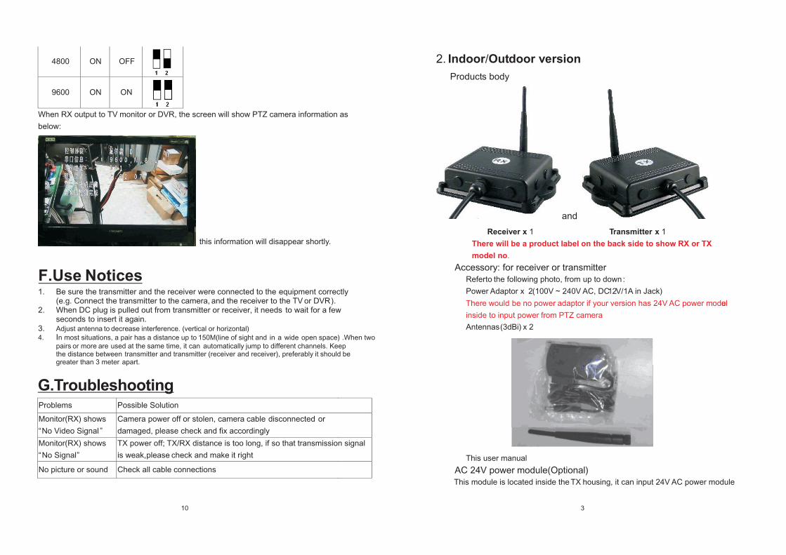
4800 ON OFF
9600 ON ON
When RX output to TV monitor or DVR, the screen will show PTZ camera information as
below:
this information will disappear shortly.
1. Be sure the transmitter and the receiver were connected to the
equipment correctly(e.g. Connect the transmitter to the camera,
and the receiver to the TV
or DVR ).
2. When DC plug is pulled out from transmitter or receiver, it needs to wait for a fewseconds to insert it again.
3. Adjust antenna to decrease interference. (vertical or horizontal)
4. In most situations, a pair has a distance up to 150M(line of sight and in a wide open space) .When two
pairs or more are used at the same time, it can automatically jump to different channels. Keepthe distance between transmitter and transmitter (receiver and receiver), preferably it should begreater than 3 meter apart.
Problems Possible Solution
Monitor(RX) shows
“No Video Signal ”
Camera power off or stolen, camera cable disconnected or
damaged, please check and fix accordinglyMonitor(RX) shows
“No Signal”
TX power off; TX/RX distance is too long, if so that transmission signal
is weak, please check and make it right
No picture or sound Check all cable connections
3
2. Indoor/Outdoor version
Products body
and
Receiver
x 1 Transmitter x 1
There will be a product label on the back side to show RX or TX
model no.
Accessory: for receiver or transmitterRefer to the following photo, from up to down :
Power Adaptor x 2(100V ~ 240V AC, DC 12V/1A in Jack)
There would be no power adaptor if your version has 24V AC power module
inside to input power from PTZ camera
Antennas(3dBi) x 2
This user manual
AC 24V power module(Optional)This module is located inside the TX housing, it can input 24V AC power module
F.Use Notices
G.Troubleshooting
9
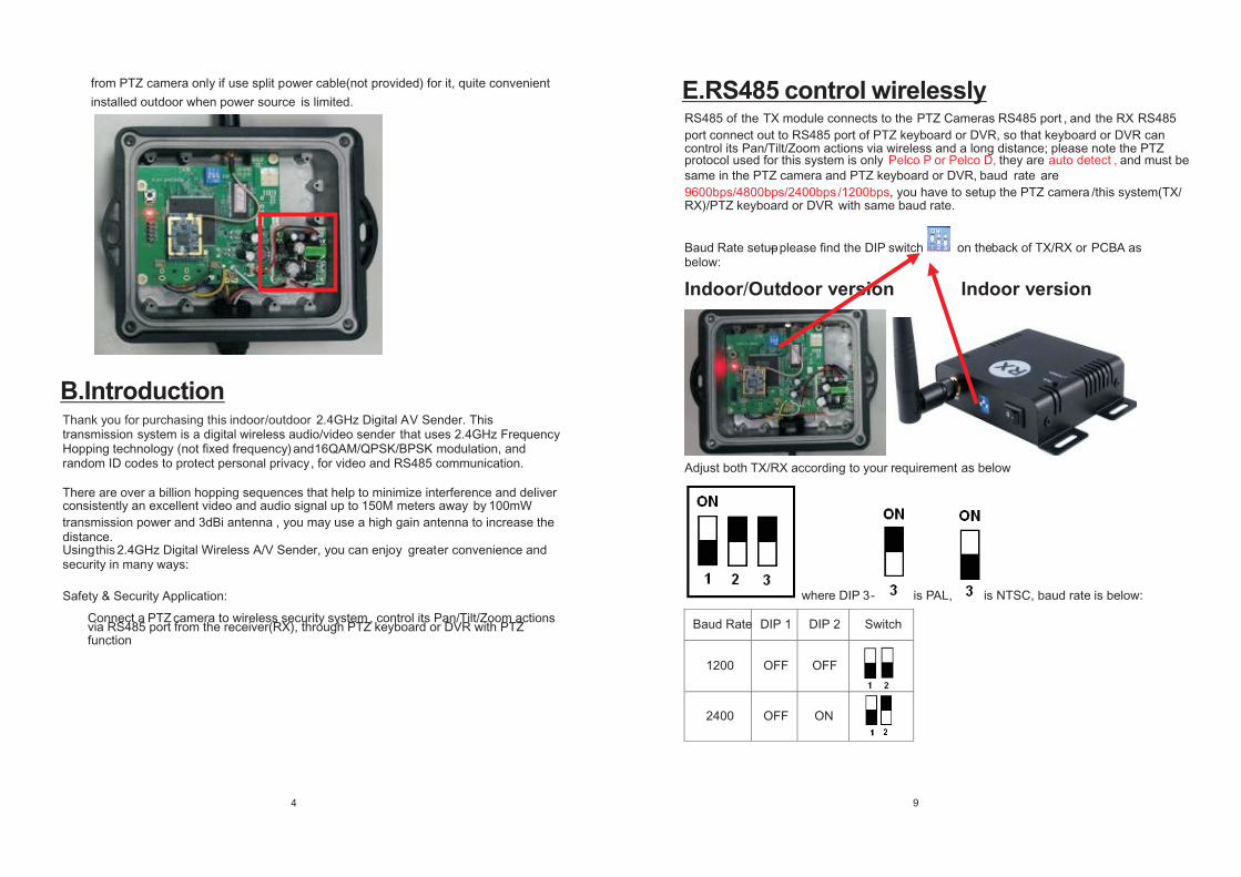
RS485 of the TX module connects to the PTZ Cameras RS485 port , and the RX RS485
port connect out to RS 485 port of PTZ keyboard or DVR, so that keyboard or DVR can control its Pan/Tilt/Zoom actions via wireless and a long distance; please note the PTZ protocol used for this system is only Pelco P or Pelco D, they are auto detect , and must be same in the PTZ camera and PTZ keyboard or DVR, baud rate are 9600bps/4800bps/2400 bps /1200bps, you have to
setup the PTZ camera /this system(TX/
RX)/PTZ keyboard or DVR with same baud rate.
Baud Rate setup – please find the DIP switch on the back of TX/RX or PCBA as below:
Indoor/Outdoor version Indoor version
Adjust both TX/RX according to your requirement as below
where DIP 3 - is PAL, is NTSC, baud rate is below:
Baud Rate DIP 1 DIP 2 Switch
1200 OFF OFF
2400 OFF ON
4
from PTZ camera only if use split power cable(not provided) for it, quite convenient
installed outdoor when power source is limited.
Thank you for purchasing this indoor/outdoor 2.4GHz Digital AV Sender. This transmission system is a digital wireless audio/video
sender
that uses 2.4GHz Frequency
Hopping technology (not fixed frequency)
and 16QAM/QPSK/BPSK
modulation, and random ID codes to protect personal privacy , for video and RS485 communication.
There are over a billion hopping sequences that help to minimize interference and deliver consistently an excellent video and audio signal up to 150M meters away by 100mW
transmission power and 3dBi antenna , you may use a high gain antenna to increase the distance.Using this 2.4GHz Digital Wireless A/V Sender, you can enjoy greater convenience and security in many ways:
Safety & Security Application:
Connect a PTZ camera to wireless security system , control its Pan/Tilt/Zoom actions via RS485 port from the receiver(RX), through PTZ keyboard or DVR with PTZ function
B.Introduction
E.RS485 control wirelessly
8
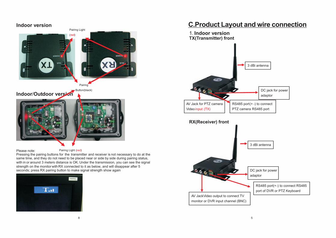
Indoor version
Indoor/Outdoor version
Please note: Pairing Light (red)
Pressing the pairing buttons for the transmitter and receiver is not necessary to do at the same time, and they do not need to be placed near or side by side during pairing status, with in or around 3 meters distance is OK
. Under
the transmission, you can see the signal
strength on the monitor with RX connected to it as below, and will disappear after 5 seconds; press RX pairing button to make signal strength show again
Pairing
Button(black)
Pairing Light
(red)
5
1. Indoor version
AV Jack for PTZ camera
Video input (TX)
DC jack for power
adaptor
RS485 port(+ -) to connect
PTZ camera RS485 port
3 dBi antenna
3 dBi antenna
DC jack for power
adaptor
RS485 port(+ -) to connect RS485
port of DVR or PTZ Keyboard
AV JackVideo output to connect TV
monitor or DVR input channel (BNC)
C.Product Layout and wire connection
TX(Transmitter) front
RX(Receiver) front
6
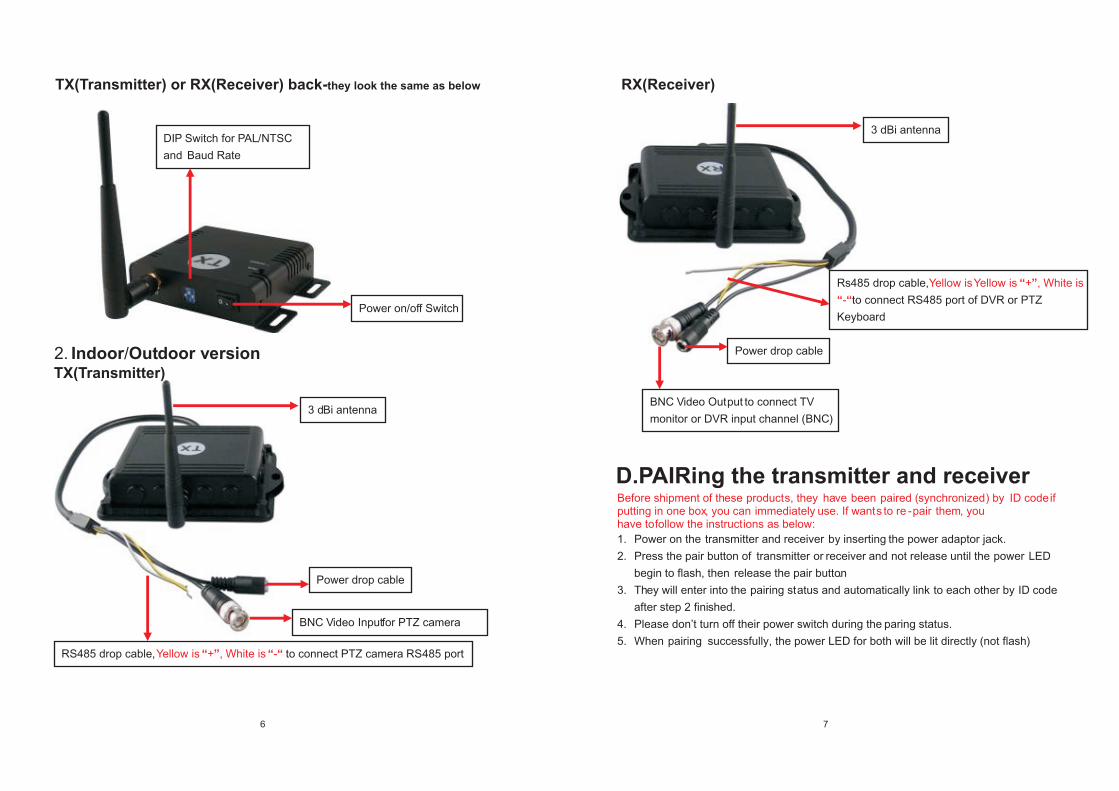
2. Indoor/Outdoor version
DIP Switch for PAL/NTSC
and Baud Rate
Power on/off Switch
3 dBi antenna
Power drop cable
BNC Video Input for PTZ camera
RS485 drop cable, Yellow is “+”, White is “-“ to connect PTZ camera RS485 port
7
Before shipment of these
products, they
have
been paired (synchronized) by ID codeif putting in one box, you can immediately use. If wants to re -pair them, you have to follow the instructions as below:
1.
Power on the transmitter and receiver by inserting the power adaptor jack.
2.
Press the pair button of transmitter
or receiver and
not release until the power LED
begin to flash, then release the pair button.
3. They will enter into the pairing status and automatically link to each other by ID code
after step 2 finished.
4. Please don’t turn off their power switch during the paring status.
5. When pairing successfully, the power LED for both will be lit directly (not flash)
3 dBi antenna
Power drop cable
BNC Video Output
to connect TV
monitor or DVR input channel (BNC)
Rs485 drop cable, Yellow isYellow is “+”, White is
“-“to connect RS485 port of DVR or PTZ
Keyboard
TX(Transmitter)
TX(Transmitter) or RX(Receiver) back-they look the same as below RX(Receiver)
D.PAIRing the transmitter and receiver