Embed Size (px)
Citation preview

Technical changes reserved -Latest updates of data sheet always under www.burster.com
burster praezisionsmesstechnik gmbh & co kg . Tel. +49-7224-6450 . Fax 64588Talstr. 1-5 . DE-76593 Gernsbach . www.burster.com . [email protected]
Code: 9180 EN
Delivery: ex stock / 4 weeks
Warranty: 24 months
9180
EN
Desktop version
Panel-mounted version
Digital DisplayFor strain gauge units, potentiometers,DC/DC sensors and standard signals
Model 9180
ApplicationModel 9180 supports force, pressure and torque sensors operating on the strain gauge principle, as well as the connection of position and angle sensors in potentiometer or DC/DC configuration. It also allows the measurement of process signals ± 1 V/ 5 V/ 10 V or 0 ...1 mA, 0(4) ... 20 mA. The current measured value is indicated on the 14 mm high LED main display, while a second display located directly below provides a reading of the peak value.The display is particularly suitable for highly accurate measurements due to the high accuracy of 0.1%. It is also possible to monitor up to 4 limit values and provide the results via relay or transistor outputs. Thus the process value display can be used for classification, process and control tasks. The current measured value is frozen on the display by activating an external HOLD signal. The TARE function is useful for balancing out previous loads for example. The optional serial interface can be used to transfer measured values and perform device settings. Powerful PC software is available for this on request.
DescriptionState-of-the-art microprocessor technology has allowed the realization of numerous special functions for practical use. Menu guidance of device setup is standard. Self-explanatory abbreviations greatly facilitate this process so that even inexperienced users can manage without operating instructions. First, the user specifies the type of input signal or sensor. Strain gauge, potentiometer or process signals 0 ...1 mA, 4 ...20 mA or ± 1 V, ± 10 V as well as DC/ DC sensors can be selected. Then the calibration process is selected. Users can choose between teach-in or calibration depending on the sensor protocol. The decimal point can be moved as required. The sensor excitation stated in the technical specifications is set automatically upon selection of the sensor type except with process signals. A choice of three excitations is available for process signals. Complete electrical isolation of the measurement channel prevents measurement values from being falsified by ground loops.
n Up to 8 sensor parameters can be saved (optional)
n For force, pressure or torque measurements using strain gauge sensors
n For distance or angle measurements with potentiometer or DC/DC sensors
n Processing of standard signals ± 1 V/ 10 V/ 0 ... 1 mA, 0 (4) ... 20 mA
n Min. or max. peak values via an additional display
n TARE and HOLD function
n Generation of up to 4 limit signals (optional)
n RS232 or RS485 (optional)
n Analog output (optional)
n Measurement accuracy < 0.1 %
n Scaling possible using teach-in procedure or by entering sensor data directly
n Convenient configuration and evaluation software DigiVision
New !Evaluation optional
via Ethernet

1760-009180EN
-5672-011516
Technical changes reserved -Latest updates of data sheet always under www.burster.com
burster praezisionsmesstechnik gmbh & co kg . Tel. +49-7224-6450 . Fax 64588Talstr. 1-5 . DE-76593 Gernsbach . www.burster.com . [email protected]
The CAD drawing (3D/2D) for this device can be imported online directly into your CAD system.Download via www.burster.com or directly at www.traceparts.com. For further information about the burster traceparts cooperation refer to data sheet 80-CAD-EN.
9180 EN - 2
Technical DataConnectable sensorsStrain gauge
Connection system: 4 wire
Bridge resistance: 120 ... 1000 ΩBridge voltage: 15/ 30/ 60/ 300 mV, selection via menu
Sensor excitation: 10 V/ 120 mA, automatic 5 V/ 120 mA*
Potentiometer
Track resistance: 500 Ω ... 10 kΩSensor excitation: 10 V/ 120 mA, automatic 5 V/ 120 mA*
Standard signals, DC/DC sensors and transmitters
Voltage input: ± 1 V/ ±10 V
Resolution: 0.1 mV respectively 1 mV
Input resistance: 1 MΩ
Current input: 0 ... 1 mA, 0 (4) ... 20 mA
Resolution: 1 µA
Load: 15 Ω
Transmitters and DC/DC sensors: 10 V/ 120 mA
Excitation: 24 V/ 30 mA 5 V/ 120 mA*Transmitters can be connected in 2, 3 or 4 wire configuration.
*) if the jumper is set (default setting)
Standard functionsPeak-value memory Minimum or maximum value on an auxiliary display, cancellation with RESET via keyboard or digital control input.
HOLD functionFreezing of the measured value on the main display.Active: via ext. HOLD signal
TARE function Balancing out an offset.The balanced-out value can also be shown on the auxiliary display.Active: via button or ext. TARE signal
Digital control inputsRESET, HOLD, TARE, MIN/MAX (opto-electrically)Active: 24 VResonse time ≤ 10 ms
General specificationsAccuracy
Resolution: 15 Bit
Measurement error: 0.1 % v. E. ± 3 digits
Temperature coefficient: 50 ppm/K
Warm-up period: 10 minutes
LED display
Main display: - 99999 ... + 99999, height 14 mm
Auxiliary display: - 99999 ... + 99999, height 8 mm
Decimal point: programmable
Measurement rate 16/sec.
Environmental conditions
Operating temperature: 0 ... 50 °C
Relative humidity: < 95 %
Protection class: Front panel IP65
Dimensions/weightPanel-mounted version: Dimensions (W x H x D): 96 x 48 x 120 mm Installation depth incl. connector: approx. 150 mm Cut-out in front panel: 92 x 44 mm Weight: 600 g Housing material: plastic
Desktop version: Dimensions (W x H x D): 155 x 90 x 210 mm Weight: 1.2 kg Housing material: metal/plastic
Electrical connection
Panel-mounted version: snap-in plug connection
Desktop version: 12 pole jacks for plug 9941
Power supply
Desktop version: 115/2301) V AC, 50/60 Hz
Panel-mounted version: 115/2301) V AC, 50/60 Hz
or 24/481) V AC, 50/60 Hz Power consumption: 5 VA without options 10 VA with all options1)Switch over by means of a jumper
OptionsDigital set point alarm outputs
2 relay contacts 250 VAC/ 150 VDC/ 8 A, for 2 limiting values or
4 relay contacts 50 VAC/ DC/ 0.2 A, for 4 limiting values or
4 transistors open C. switching n or open E. switching P, 50 V/ 50 mA for 4 limits each, opto-decoupled
Response time: 250 ... 750 ms, depending on the filter setting
Analog output Ranges: Voltage 0 ... 10 V Load > 50 Ω Drift 0,2 mV/K or Current 4 ... 20 mA Load < 800 Ω Drift 0,5 µA/K (Selection between 0 ... 10 V and 4 ... 20 mA via the menu)
Resolution: 12 Bit
Potential separation to signal input
Accuracy: 0.1 % F.S.
Signal response time: 60 ms
Serial interface
RS232 (V.24) or RS485 (half duplex)
Baud rate: 1200 ... 19200
Data transmission rate: 10 values/sec. at 19200 baud
Networking via RS485 by means of a converter (model 9180-Z001)
BCD interface
Level: 24 V/ TTL The BCD option excludes all other options.
The options analog output; RS232 or RS485 (only one) and 2 relays, 4 relays or 4 O.C. (only one);can be used simultaneously.
CalibrationTwo basic procedures are possible; in both cases, one display value is allocated to two input variables each (two-point calibration):
1. In the teach-in mode, the two input variables are applied physically as measurement signals to the input. These are assigned to the corresponding display values by pressing an enter key.
2. During calibration in accordance with the sensor protocol, the two signals are not applied physically, but read off from the sensor protocol and entered via the keyboard.
RS
485
Technical changes reserved -Latest updates of data sheet always under www.burster.com
burster praezisionsmesstechnik gmbh & co kg . Tel. +49-7224-6450 . Fax 64588Talstr. 1-5 . DE-76593 Gernsbach . www.burster.com . [email protected]
9180 EN - 3
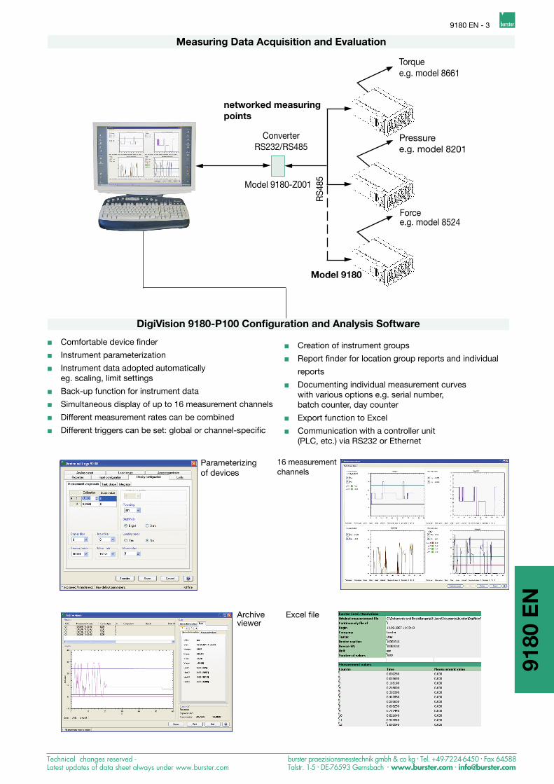
Measuring Data Acquisition and Evaluation
9180
EN
DigiVision 9180-P100 Configuration and Analysis Software
Parameterizingof devices
Archiveviewer
16 measurement channels
Excel file
ConverterRS232/RS485
Model 9180-Z001
Model 9180
Pressuree.g. model 8201
Forcee.g. model 8524
networked measuringpoints
Torquee.g. model 8661
n Creation of instrument groups
n Report finder for location group reports and individual
reports
n Documenting individual measurement curves with various options e.g. serial number, batch counter, day counter
n Export function to Excel
n Communication with a controller unit (PLC, etc.) via RS232 or Ethernet
n Comfortable device finder
n Instrument parameterization
n Instrument data adopted automatically eg. scaling, limit settings
n Back-up function for instrument data
n Simultaneous display of up to 16 measurement channels
n Different measurement rates can be combined
n Different triggers can be set: global or channel-specific

1760-009180EN
-5672-011516
Technical changes reserved -Latest updates of data sheet always under www.burster.com
burster praezisionsmesstechnik gmbh & co kg . Tel. +49-7224-6450 . Fax 64588Talstr. 1-5 . DE-76593 Gernsbach . www.burster.com . [email protected]
Order Code
Digital indicator
Version model 9180 - V
8 sensor parameters
Options on extra charge:
Displays and Operating Panel
Keys for configuration, tare, limiting
LEDs forrelaysstatus(optional)
Mains display formeasurement value
Auxiliary display formin, max or tare value
Multichannel Measurement Systems for any Numbers of Channels in Desktop Housing (please enquire)
Panel seal
Dimensions Mounting Rear Connection
Fasteningclips
Front panel
Clamping connection
0 0 0 0
1) - Important! The BCD option does not allow any additional options (limiting value or analog output) and is not available as desktop version either.
Cut-out infront panel92 x 44 mm
AccessoriesInstrument calibration for one sensor ordered with the instrument or using sensor data provided by the costumer (e.g. sensitivity, display range of correct reading, excitation voltage or sensor test certificate) (Please specify the calibration data precisely!) Model 91ABG
If calibration data not communicated, it will be calibrated as standard sensor-specified.
Strain gauge simulator Model 9405See data sheet 76-9405 insection 7 of the Sensors andProcess Instruments catalog.
DigiVision 9180-P100 configuration and analysis software for device series 9180Enables an easy storage of device data, graphical visualization,storage and logging of measurement data Model 9180-P100
Converter RS232/RS485Cartridge with RS485 applications for maximum 32 participantsmains adapter included Model 9180-Z001
Indicator for angle, pulses or rotation on request
Data cable for connection of desktop version and PC Model 9900-K333for connection of panel version and PC Model 9180-K001Interface adapter USB-RS232 Model 9900-K361Networking via RS232 requires Ethernet Model 9900-K453
9180 EN - 4
Back view:All sockets forsensors, control signals and serial interfaces are com-pletely installed.
Front view:Up to 16 panel-meters in one common housing possible.
-1
Housing and power supply Panel-mounted version 115/230V-50/60 Hz 0 Panel-mounted version 24/48V-50/60 Hz 1 Desktop version 115/230V-50/60 Hz 3 Desktop version 24/48V-50/60 Hz 6
Analog output without 0 0 ... 10 V / 4 ... 20 mA 1
Interface without 0 RS232 1 RS485 2 BCD1) 3
Set point alarm outputs without 0 2 relays 1 4 relays 2 4 transistor open C. n-switched 3 4 transistor open E. p-switched 4
LEDMin/Max
LEDTare/Peak
Additional display shows program steps)


![BCD & Accessories 2010 - nemo-sub.comEN][PreVer].pdf · Page BC4| BCD & Accessories BCD & Accessories| Page 5 The BC-87 Elite Pro from AQUATEC™ is an internal bladderless BCD that](https://img.pdfslide.net/doc/110x75/5ea4f75f48423e5c5a379918/bcd-accessories-2010-nemo-sub-enpreverpdf-page-bc4-bcd-accessories.jpg)