Embed Size (px)
Citation preview
Digital Encoding And Decoding
Dr. George W Benthien
August 13, 2007
Revised March 30, 2010
E-mail: [email protected]
1 Introduction
Many electronic communication devices today process and transfer information digitally. Exam-ples are cable televisions, cell phones, cable/DSL modems, and wireless routers. Digital informa-tion is specified by a sequence of zeroes and ones such as 1101010001. Each zero or one is calleda binary digit or bit. Digital information is usually embedded in an electric or optical signal. Thisarticle describes a number of methods for encoding digital information in an electric or opticalsignal and later extracting this information. I have divided these methods into two types. The firsttype (sometimes referred to as baseband) involves the encoding of digital information in digitalsignals consisting of a sequence of rectangular pulses. These methods are used primarily in localarea Ethernet networks. The second type often referred to as broadband) involves modulation ofone or more sinusoidal carrier waves. These methods are used in cable/DSL broadband networks,satellite communication, cell phones, digital TV, and wireless networks. Some of the specific tech-niques that will be discussed are Manchester encoding, 4B/5B block encoding, MLT-3 encoding,Frequency Shift Keying (FSK), Quadrature Phase Shift Keying (QPSK), Quadrature AmplitudeModulation (QAM), Orthogonal Frequency Division Multiplexing (OFDM), Frequency HoppingSpread Spectrum (FHSS), and Direct-Sequence Spread Spectrum (DSSS).
In digital encoding time is broken up into a succession of equal time intervals of length T . In eachtime interval either one or a group of bits of the given sequence are encoded in the signal. T iscalled the symbol period and the group of bits encoded during a time interval T is called a symbol.The rate at which symbols are encoded is called the baud rate. The rate at which bits are encodedis called the bit rate.
2 Encoding Digital Information in Digital Signals
A digital signal consists of a sequence of equal width rectangular pulses. The timing of the pulsesis controlled by an internal clock whose output is an alternating sequence of high and low valuedrectangular pulses. A high/low pair is called a clock cycle.
2.1 NRZ encoding
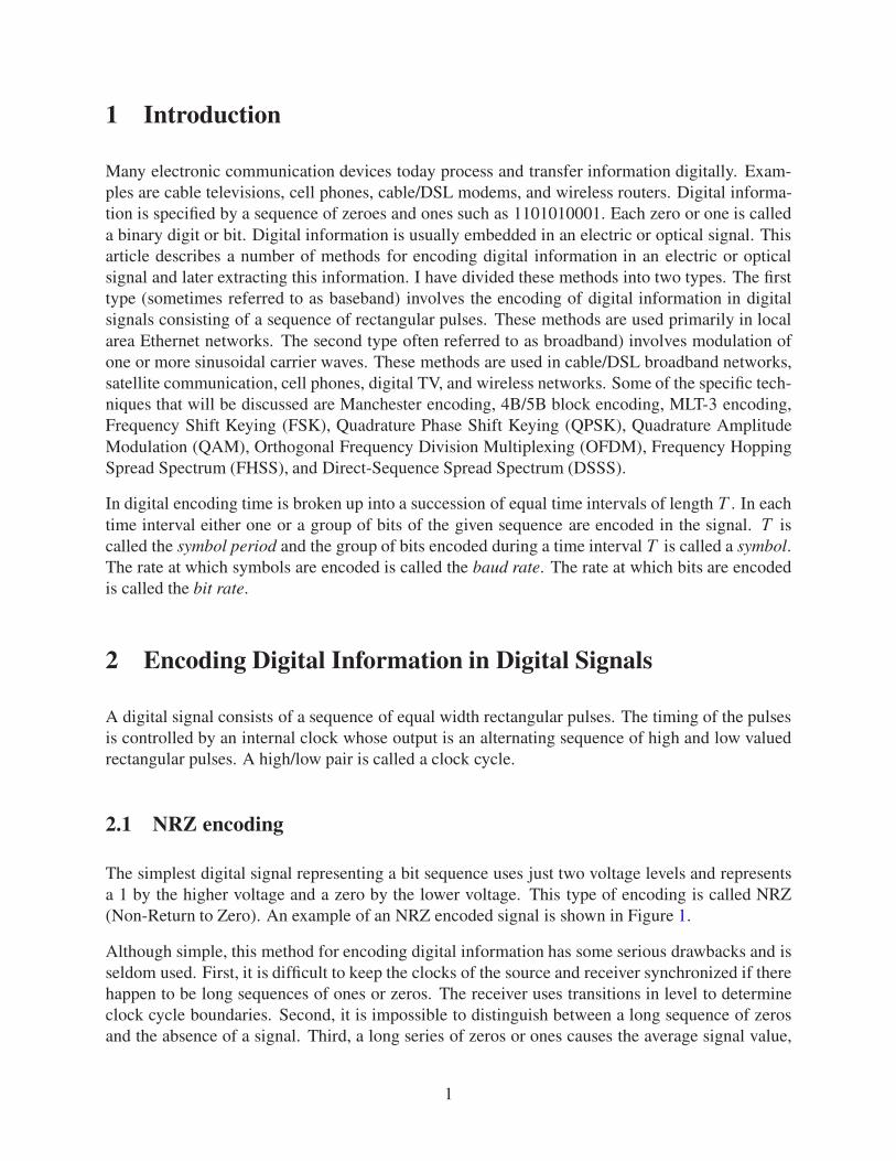
The simplest digital signal representing a bit sequence uses just two voltage levels and representsa 1 by the higher voltage and a zero by the lower voltage. This type of encoding is called NRZ(Non-Return to Zero). An example of an NRZ encoded signal is shown in Figure 1.
Although simple, this method for encoding digital information has some serious drawbacks and isseldom used. First, it is difficult to keep the clocks of the source and receiver synchronized if therehappen to be long sequences of ones or zeros. The receiver uses transitions in level to determineclock cycle boundaries. Second, it is impossible to distinguish between a long sequence of zerosand the absence of a signal. Third, a long series of zeros or ones causes the average signal value,
1
Data bits
NRZ
1 0 0 1 0 1 1 0 1 0 0 1
Clock
Figure 1: Example of NRZ encoding.
which is used to distinguish between high and low values, to drift. Thus, for many reasons, it isdesirable to have frequent transitions between the high and low values.
2.2 NRZI encoding
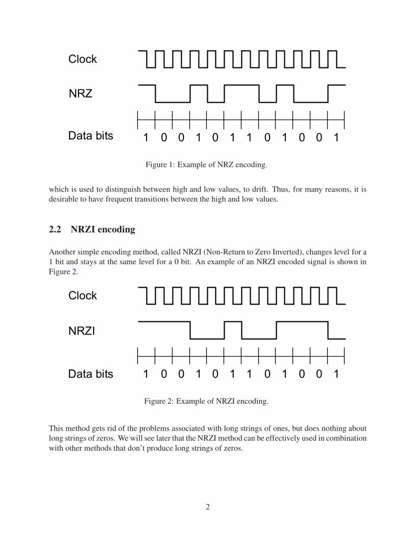
Another simple encoding method, called NRZI (Non-Return to Zero Inverted), changes level for a1 bit and stays at the same level for a 0 bit. An example of an NRZI encoded signal is shown inFigure 2.
Data bits
NRZI
1 0 0 1 0 1 1 0 1 0 0 1
Clock
Figure 2: Example of NRZI encoding.
This method gets rid of the problems associated with long strings of ones, but does nothing aboutlong strings of zeros. We will see later that the NRZI method can be effectively used in combinationwith other methods that don’t produce long strings of zeros.
2
2.3 Manchester encoding
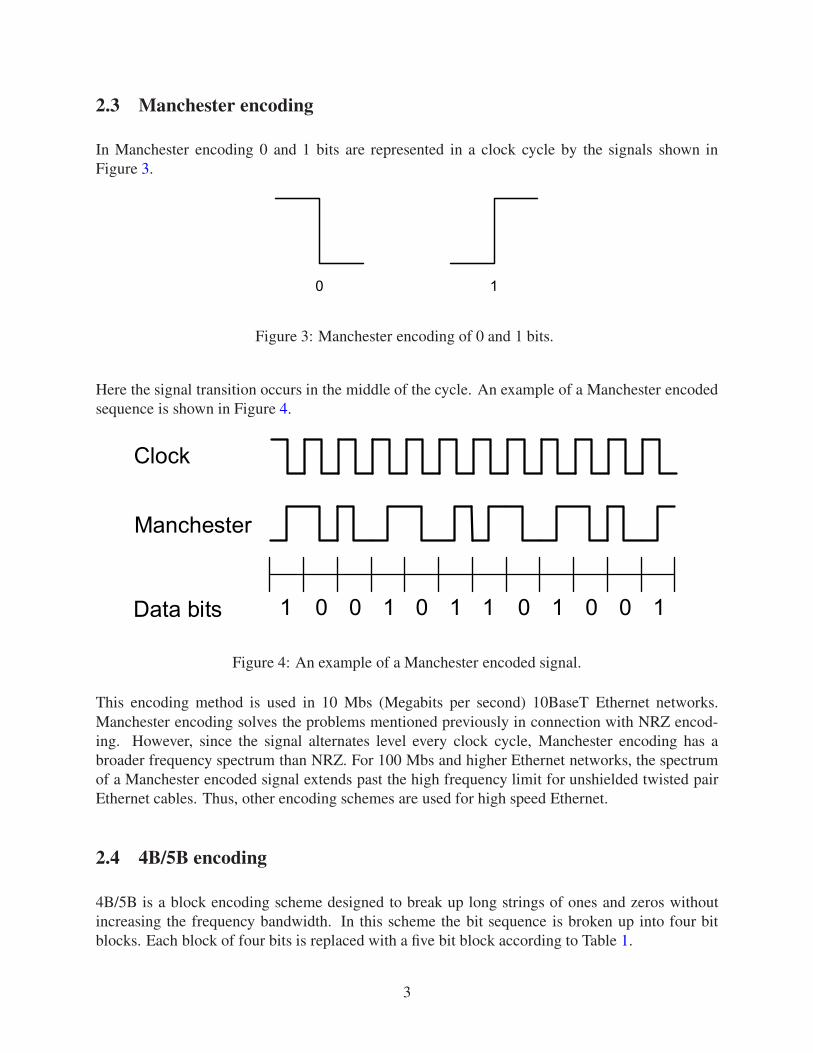
In Manchester encoding 0 and 1 bits are represented in a clock cycle by the signals shown inFigure 3.
0 1
Figure 3: Manchester encoding of 0 and 1 bits.
Here the signal transition occurs in the middle of the cycle. An example of a Manchester encodedsequence is shown in Figure 4.
Data bits
Manchester
1 0 0 1 0 1 1 0 1 0 0 1
Clock
Figure 4: An example of a Manchester encoded signal.
This encoding method is used in 10 Mbs (Megabits per second) 10BaseT Ethernet networks.Manchester encoding solves the problems mentioned previously in connection with NRZ encod-ing. However, since the signal alternates level every clock cycle, Manchester encoding has abroader frequency spectrum than NRZ. For 100 Mbs and higher Ethernet networks, the spectrumof a Manchester encoded signal extends past the high frequency limit for unshielded twisted pairEthernet cables. Thus, other encoding schemes are used for high speed Ethernet.
2.4 4B/5B encoding
4B/5B is a block encoding scheme designed to break up long strings of ones and zeros withoutincreasing the frequency bandwidth. In this scheme the bit sequence is broken up into four bitblocks. Each block of four bits is replaced with a five bit block according to Table 1.
3
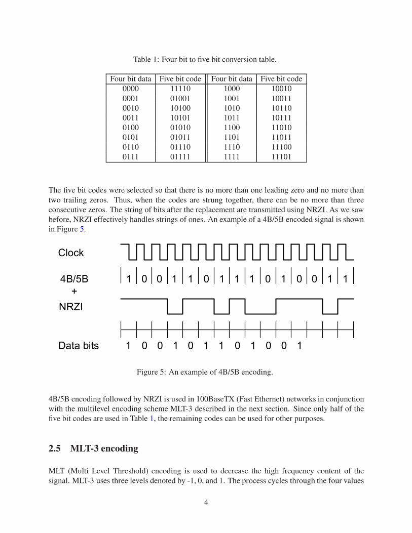
Table 1: Four bit to five bit conversion table.
Four bit data Five bit code Four bit data Five bit code0000 11110 1000 100100001 01001 1001 100110010 10100 1010 101100011 10101 1011 101110100 01010 1100 110100101 01011 1101 110110110 01110 1110 111000111 01111 1111 11101
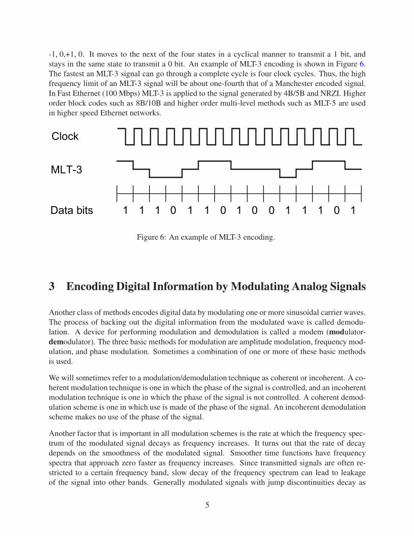
The five bit codes were selected so that there is no more than one leading zero and no more thantwo trailing zeros. Thus, when the codes are strung together, there can be no more than threeconsecutive zeros. The string of bits after the replacement are transmitted using NRZI. As we sawbefore, NRZI effectively handles strings of ones. An example of a 4B/5B encoded signal is shownin Figure 5.
Data bits 1 0 0 1 0 1 1 0 1 0 0 1
Clock
1 0 0 1 0 1 14B/5B 1 0 1 1 1 0 1 0
NRZI+
Figure 5: An example of 4B/5B encoding.
4B/5B encoding followed by NRZI is used in 100BaseTX (Fast Ethernet) networks in conjunctionwith the multilevel encoding scheme MLT-3 described in the next section. Since only half of thefive bit codes are used in Table 1, the remaining codes can be used for other purposes.
2.5 MLT-3 encoding
MLT (Multi Level Threshold) encoding is used to decrease the high frequency content of thesignal. MLT-3 uses three levels denoted by -1, 0, and 1. The process cycles through the four values
4
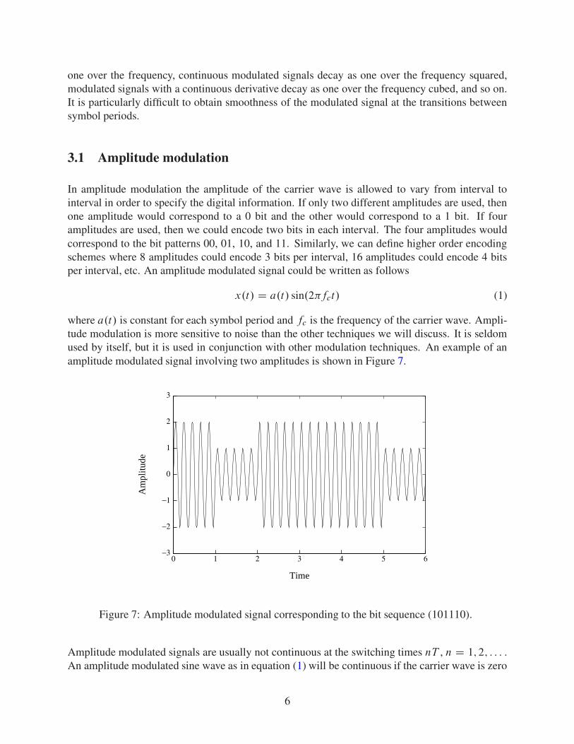
-1, 0,+1, 0. It moves to the next of the four states in a cyclical manner to transmit a 1 bit, andstays in the same state to transmit a 0 bit. An example of MLT-3 encoding is shown in Figure 6.The fastest an MLT-3 signal can go through a complete cycle is four clock cycles. Thus, the highfrequency limit of an MLT-3 signal will be about one-fourth that of a Manchester encoded signal.In Fast Ethernet (100 Mbps) MLT-3 is applied to the signal generated by 4B/5B and NRZI. Higherorder block codes such as 8B/10B and higher order multi-level methods such as MLT-5 are usedin higher speed Ethernet networks.
Data bits
Clock
1 1 1 0 1 0 11 1 0 1 0 0 1 1
MLT-3
Figure 6: An example of MLT-3 encoding.
3 Encoding Digital Information by Modulating Analog Signals
Another class of methods encodes digital data by modulating one or more sinusoidal carrier waves.The process of backing out the digital information from the modulated wave is called demodu-lation. A device for performing modulation and demodulation is called a modem (modulator-demodulator). The three basic methods for modulation are amplitude modulation, frequency mod-ulation, and phase modulation. Sometimes a combination of one or more of these basic methodsis used.
We will sometimes refer to a modulation/demodulation technique as coherent or incoherent. A co-herent modulation technique is one in which the phase of the signal is controlled, and an incoherentmodulation technique is one in which the phase of the signal is not controlled. A coherent demod-ulation scheme is one in which use is made of the phase of the signal. An incoherent demodulationscheme makes no use of the phase of the signal.
Another factor that is important in all modulation schemes is the rate at which the frequency spec-trum of the modulated signal decays as frequency increases. It turns out that the rate of decaydepends on the smoothness of the modulated signal. Smoother time functions have frequencyspectra that approach zero faster as frequency increases. Since transmitted signals are often re-stricted to a certain frequency band, slow decay of the frequency spectrum can lead to leakageof the signal into other bands. Generally modulated signals with jump discontinuities decay as
5
one over the frequency, continuous modulated signals decay as one over the frequency squared,modulated signals with a continuous derivative decay as one over the frequency cubed, and so on.It is particularly difficult to obtain smoothness of the modulated signal at the transitions betweensymbol periods.
3.1 Amplitude modulation
In amplitude modulation the amplitude of the carrier wave is allowed to vary from interval tointerval in order to specify the digital information. If only two different amplitudes are used, thenone amplitude would correspond to a 0 bit and the other would correspond to a 1 bit. If fouramplitudes are used, then we could encode two bits in each interval. The four amplitudes wouldcorrespond to the bit patterns 00, 01, 10, and 11. Similarly, we can define higher order encodingschemes where 8 amplitudes could encode 3 bits per interval, 16 amplitudes could encode 4 bitsper interval, etc. An amplitude modulated signal could be written as follows
x.t/ D a.t/ sin.2�fct/ (1)
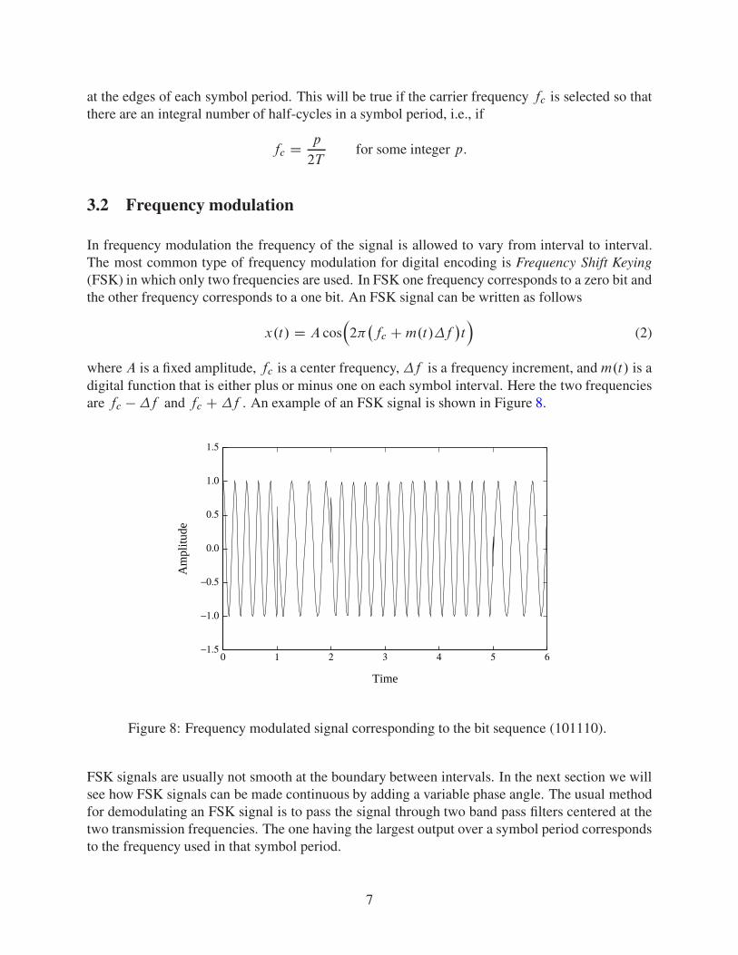
where a.t/ is constant for each symbol period and fc is the frequency of the carrier wave. Ampli-tude modulation is more sensitive to noise than the other techniques we will discuss. It is seldomused by itself, but it is used in conjunction with other modulation techniques. An example of anamplitude modulated signal involving two amplitudes is shown in Figure 7.
0 1 2 3 4 5 6
Time
−3
−2
−1
0
1
2
3
Am
plitu
de
Figure 7: Amplitude modulated signal corresponding to the bit sequence (101110).
Amplitude modulated signals are usually not continuous at the switching times nT , n D 1; 2; : : : .An amplitude modulated sine wave as in equation (1) will be continuous if the carrier wave is zero
6
at the edges of each symbol period. This will be true if the carrier frequency fc is selected so thatthere are an integral number of half-cycles in a symbol period, i.e., if
fc D p
2Tfor some integer p.
3.2 Frequency modulation
In frequency modulation the frequency of the signal is allowed to vary from interval to interval.The most common type of frequency modulation for digital encoding is Frequency Shift Keying(FSK) in which only two frequencies are used. In FSK one frequency corresponds to a zero bit andthe other frequency corresponds to a one bit. An FSK signal can be written as follows
x.t/ D A cos�2�
�fc C m.t/�f
�t�
(2)
where A is a fixed amplitude, fc is a center frequency, �f is a frequency increment, and m.t/ is adigital function that is either plus or minus one on each symbol interval. Here the two frequenciesare fc � �f and fc C �f . An example of an FSK signal is shown in Figure 8.
0 1 2 3 4 5 6
Time
−1.5
−1.0
−0.5
0.0
0.5
1.0
1.5
Am
plitu
de
Figure 8: Frequency modulated signal corresponding to the bit sequence (101110).
FSK signals are usually not smooth at the boundary between intervals. In the next section we willsee how FSK signals can be made continuous by adding a variable phase angle. The usual methodfor demodulating an FSK signal is to pass the signal through two band pass filters centered at thetwo transmission frequencies. The one having the largest output over a symbol period correspondsto the frequency used in that symbol period.
7
3.3 Continuous Phase FSK Modulation (CPFSK)
A continuous phase FSK signal has the form
x.t/ D A cos�2�fct C 2��f
Z t
0
m.�/ d��: (3)
where m is a digital message signal that is constant on each time interval of width T . The argumentof the cosine is continuous and hence x.t/ is continuous. If t is in the interval nT � t � .nC1/T ,then
Z t
0
m.�/ d� D T
n�1XkD0
mk C .t � nT /mn
D mnt C�T
n�1XkD0
mk � nT mn
�
D mnt C �n=.2��f / (4)
where mk is the value of m.t/ in the interval�kT; .k C 1/T
�and
�n D 2��f�
T
n�1XkD0
mk � nT mn
�:
Substituting equation (4) into equation (3), we get
x.t/ D A cos.2�fct C 2�mn�f t C �n/ for nT � t � .n C 1/T : (5)
Thus, x.t/ is a continuous FSK signal with an added phase term in each interval. In a later sectionwe will look at Minimum Shift Keying (MSK) which is an important subclass of CPFSK signals.
3.4 Phase modulation
Phase modulation uses signals of the form
x.t/ D A cos�2�fct C �.t/
�(6)
where �.t/ can take on one of a finite set of values in each symbol period. The signal in equation (6)can be written in the alternate form
x.t/ D I.t/ cos.2�fct/ C Q.t/ sin.2�fct/ (7)
where I.t/ D A cos �.t/ and Q.t/ D A sin �.t/. A two-dimensional plot of the possible pairs.I; Q/ is called a constellation diagram.
8
Phase modulated signals are usually demodulated using a coherent scheme. Multiplying the signalx.t/ in equation (7) by cos.2�fct/ and using trigonometric formulas for double angles, we get
x.t/ cos.2�fct/ D I.t/ cos2.2�fct/ C Q.t/sin.2�fct/cos.2�fct/
D 12I.t/Œ1 C cos.4�fct/� C 1
2Q.t/ sin.4�fct/: (8)
Passing x.t/ cos.2�fct/ through a low-pass filter gives 12I.t/. Multiplying the signal x.t/ by
sin.2�fct/ and using trigonometric formulas for double angles, we get
x.t/ sin.2�fct/ D I.t/sin.2�fct/cos.2�fct/ C Q.t/ sin2.2�fct/
D 12I.t/ sin.4�fct/ C 1
2Q.t/Œ1 � cos.4�fct/�: (9)
Passing x.t/ sin.2�fct/ through a low-pass filter gives 12Q.t/. The closest point to .I; Q/ in the
constellation diagram is used to obtain the symbol.
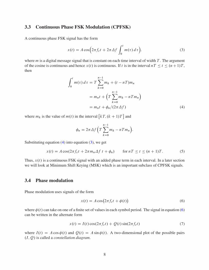
One of the most popular forms of phase modulation is Quadrature Phase Shift Keying (QPSK). InQPSK the phase �.t/ takes on one of the four values �=4, 3�=4, 5�=4, or 7�=4 in each symbolperiod. The signals corresponding to these four phase angles are A
�cos.2�fct/� sin.2�fct/
�=p
2,A
�� cos.2�fct/ � sin.2�fct/�=p
2, A�� cos.2�fct/ C sin.2�fct/
�=p
2, and A�cos.2�fct/ C
sin.2�fct/�=p
2. If we let A D p2, then the pair .I; Q/ takes on the values .1; �1/, .�1; �1/,
.�1; 1/, and .1; 1/. Each signal x.t/ corresponds to a unique pair .I; Q/. Figure 9 shows the pointscorresponding to the pairs .I; Q/ for QPSK along with the associated symbols.
I
Q
1000
01 11
Figure 9: Constellation diagram for QPSK modulation.
The points in this constellation diagram are often associated with points in the complex plane.For phase shift keying the points in the constellation diagram all lie on a circle. QPSK can beeasily generated using equation (7). Let d.t/ be a digital signal representing the bit sequenceto be encoded. Choose d.t/ to be -1 on an interval for a zero bit and +1 on an interval for aone bit. Let d0; d1: : : : be the successive values of d.t/. Define dI .t/ to be a digital signal with
9
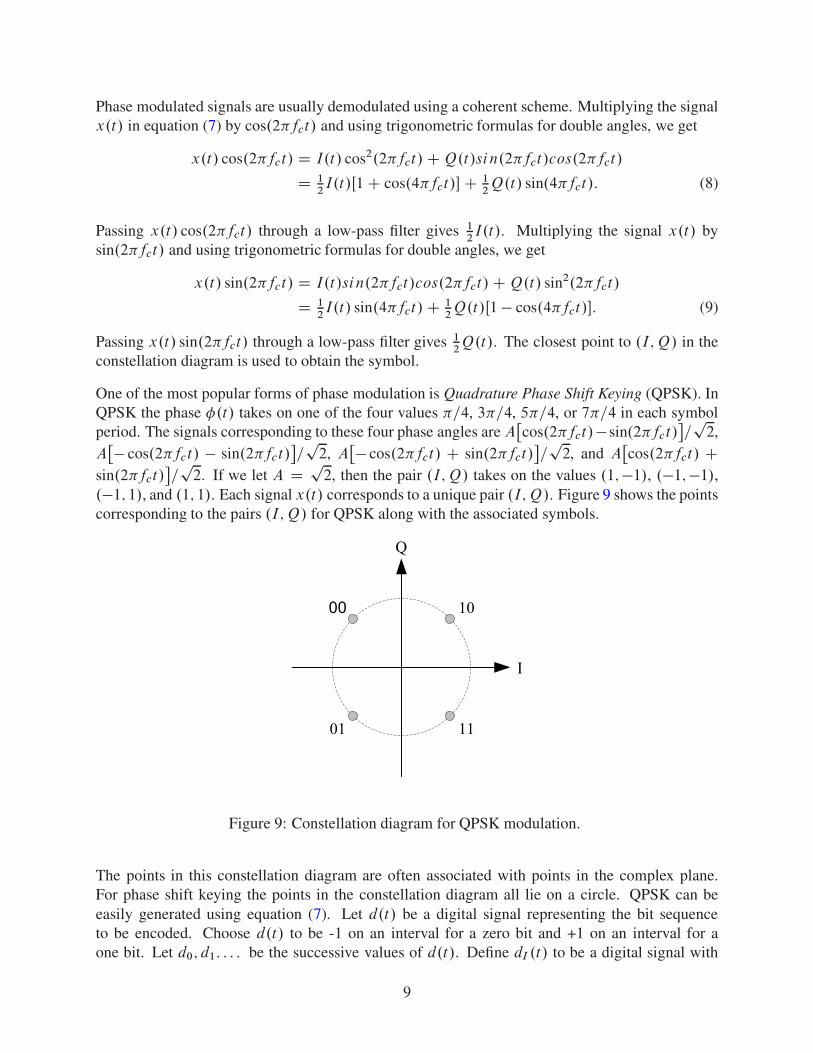
symbol period 2T representing the even values d0; d2; : : : . Define dQ.t/ to be a digital signalwith symbol period 2T representing the odd values d1; d3; : : : . Figure 10 shows the signals d ,dI , and dQ corresponding to the bit sequence 11000111. The QPSK signal is obtained by lettingI.t/ D AdI .t/=
p2 and Q.t/ D AdQ.t/=
p2.
d(t) d0 d1
d2 d3 d4
d5 d6 d7
t
dI(t)d0
d2 d4
d6
t
dQ(t) d1
d3
d5 d7
t
2TT 8T3T 4T 5T 6T 7T0
Figure 10: Digital signals used in QPSK modulation.
The form of QPSK we have constructed has the same bit rate as the original, but the symbol periodis doubled. Doubling the symbol period has the effect of narrowing the frequency bandwidth ofthe signal. We could have kept the same symbol period for the QPSK signal and the bit rate wouldthen have doubled.
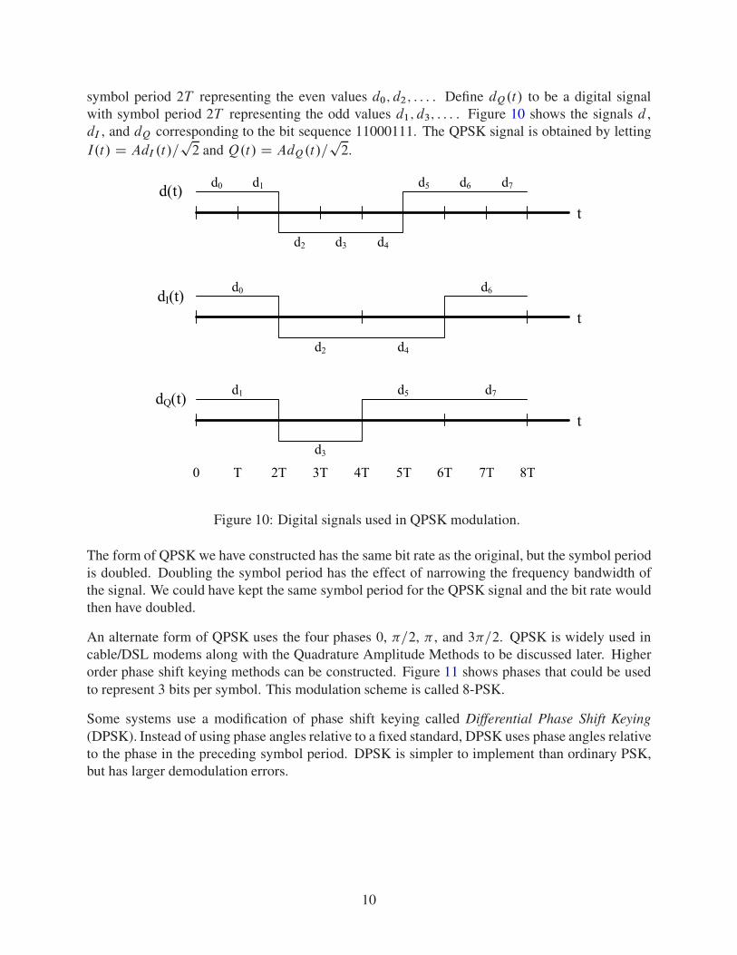
An alternate form of QPSK uses the four phases 0, �=2, � , and 3�=2. QPSK is widely used incable/DSL modems along with the Quadrature Amplitude Methods to be discussed later. Higherorder phase shift keying methods can be constructed. Figure 11 shows phases that could be usedto represent 3 bits per symbol. This modulation scheme is called 8-PSK.
Some systems use a modification of phase shift keying called Differential Phase Shift Keying(DPSK). Instead of using phase angles relative to a fixed standard, DPSK uses phase angles relativeto the phase in the preceding symbol period. DPSK is simpler to implement than ordinary PSK,but has larger demodulation errors.
10
101
001
000
010
011
111
110
100
Q
I
Figure 11: Constellation diagram for 8-PSK modulation.
3.5 Minimum Shift Keying (MSK)
The goal of minimum shift keying is to obtain a smoother signal and thus a faster decaying fre-quency spectrum. There are several ways to approach MSK. We will consider MSK as a modifi-cation of QPSK. In QPSK we modulated the carrier waves cos 2�fct and sin 2�fct by the digitalsignals dI .t/ and dQ.t/. Suppose that we replace the square pulses in dI and dQ by half cyclesinusoidal pulses as in
x.t/ D dI .t/ cos� �t
2T
�cos.2�fct/ C dQ.t/ sin
� �t
2T
�sin.2�fct/ (10)
where dI .t/ and dQ.t/ are the same digital signals used previously. The functions dI and dQ
are continuous at odd multiples of T , and sin�
�t2T
�is zero at even multiples of T . Therefore, the
second term on the right-hand-side of equation (10) is continuous. Since cos�
�t2T
�vanishes at odd
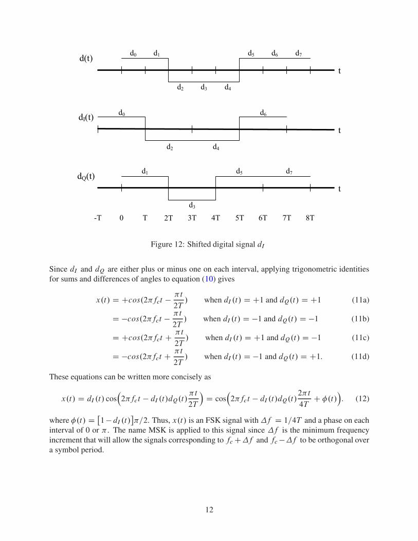
multiples of T , the signal x.t/ will be continuous if we can modify dI .t/ so that it is continuousat even multiples of T . This is easily done. We only need to shift dI .t/ to the left by T as isillustrated in Figure 12. With this modification x.t/ is called an MSK signal. We will now showthat the MSK signal x.t/ is in fact a continuous phase FSK signal.
11
d(t) d0 d1
d2 d3 d4
d5 d6 d7
t
dI(t)d0
d2 d4
d6
t
dQ(t) d1
d3
d5 d7
t
2TT 8T3T 4T 5T 6T 7T0-T
Figure 12: Shifted digital signal dI
Since dI and dQ are either plus or minus one on each interval, applying trigonometric identitiesfor sums and differences of angles to equation (10) gives
x.t/ D Ccos.2�fct � �t
2T/ when dI .t/ D C1 and dQ.t/ D C1 (11a)
D �cos.2�fct � �t
2T/ when dI .t/ D �1 and dQ.t/ D �1 (11b)
D Ccos.2�fct C �t
2T/ when dI .t/ D C1 and dQ.t/ D �1 (11c)
D �cos.2�fct C �t
2T/ when dI .t/ D �1 and dQ.t/ D C1: (11d)
These equations can be written more concisely as
x.t/ D dI .t/ cos�2�fct � dI .t/dQ.t/
�t
2T
�D cos
�2�fct � dI .t/dQ.t/
2�t
4TC �.t/
�: (12)
where �.t/ D �1 � dI .t/
��=2. Thus, x.t/ is an FSK signal with �f D 1=4T and a phase on each
interval of 0 or � . The name MSK is applied to this signal since �f is the minimum frequencyincrement that will allow the signals corresponding to fc C�f and fc ��f to be orthogonal overa symbol period.
12
Let us now look at the derivative of x.t/. Differentiating equation (10), we obtain
Px.t/ D dI .t/
�� �
2Tsin
� �t
2T
�cos.2�fct/ � 2�fc cos
� �t
2T
�sin.2�fct/
C dQ.t/
�� �
2Tcos
� �t
2T
�sin.2�fct/ C 2�fc sin
� �t
2T
�cos.2�fct/
Dh�dI .t/
�
2TC dQ.t/2�fc
isin
� �t
2T
�cos.2�fct/
Ch�dI .t/2�fc C dQ.t/
�
2T
icos
� �t
2T
�sin.2�fct/: (13)
Since sin�
�t2T
�is zero for t an even multiple of T and cos
��t2T
�is zero for t an odd multiple of T ,
Px.t/ will be zero at all multiples of T if fc is chosen so that
cos.2�fct/ D 0 for t an odd multiple of T
sin.2�fct/ D 0 for t an even multiple of T .
These conditions will hold if fc is an odd multiple of �f D 1=4T . If fc is chosen in this way,then the MSK signal will not only be continuous, but will have a continuous derivative.
We mentioned earlier that the �f used in MSK was the smallest increment that allowed the signalscorresponding to fc C �f and fc � �f to be orthogonal over every symbol period. Let us looknow at the conditions necessary for orthogonality. Using trigonometric identities for the sum anddifference of two angles we obtainZ .nC1/T
nT
cos�2�.fc C �f /t
�cos
�2�.fc � �f /t
�dt D 1
2
Z .nC1/T
nT
�cos.4�fct/ C cos.4��f t/
�dt
D 12
�sin.4�fct/
4�fc
C sin.4��f t/
4��f
.nC1/T
nT
:
(14)
For orthogonality we need this integral to vanish over each symbol period. It can be seen fromequation (14) that the integral will vanish if fc and �f satisfy the conditions
fc D p
4Tfor some integer p (15a)
�f D q
4Tfor some integer q < p: (15b)
The smallest �f satisfying the condition (15b) is the one used in MSK.
The process described for the MSK signal is not the only way to obtain a smooth FSK signal.Consider an FSK signal x.t/ of the form
x.t/ D r.t/ cos�2�fct C s.t/2��f t
�(16)
where r.t/ and s.t/ are ˙1 on each symbol interval. The only way we can hope to match slopesat the boundary between each pair of intervals is for the cosine term in equation (16) to have zero
13
slope at each boundary point nT , n D 1; 2; : : : . The value of the cosine at the zero slope pointsis ˙1. If we can match the zero slopes, then the function r.t/ can be chosen so as to match thevalues at this boundary. Therefore, we want the conditions
cos�2�.fc C �f /nT
� D ˙1 (17a)
cos�2�.fc � �f /nT
� D ˙1 (17b)
to hold for all n. These conditions will hold if fc and �f satisfy the following relations
2.fc C �f /T D p for some integer p (18a)2.fc � �f /T D q for some integer q < p: (18b)
By adding and subtracting equations (18a) and (18b) we obtain
fc D p C q
4T(19)
�f D p � q
4T: (20)
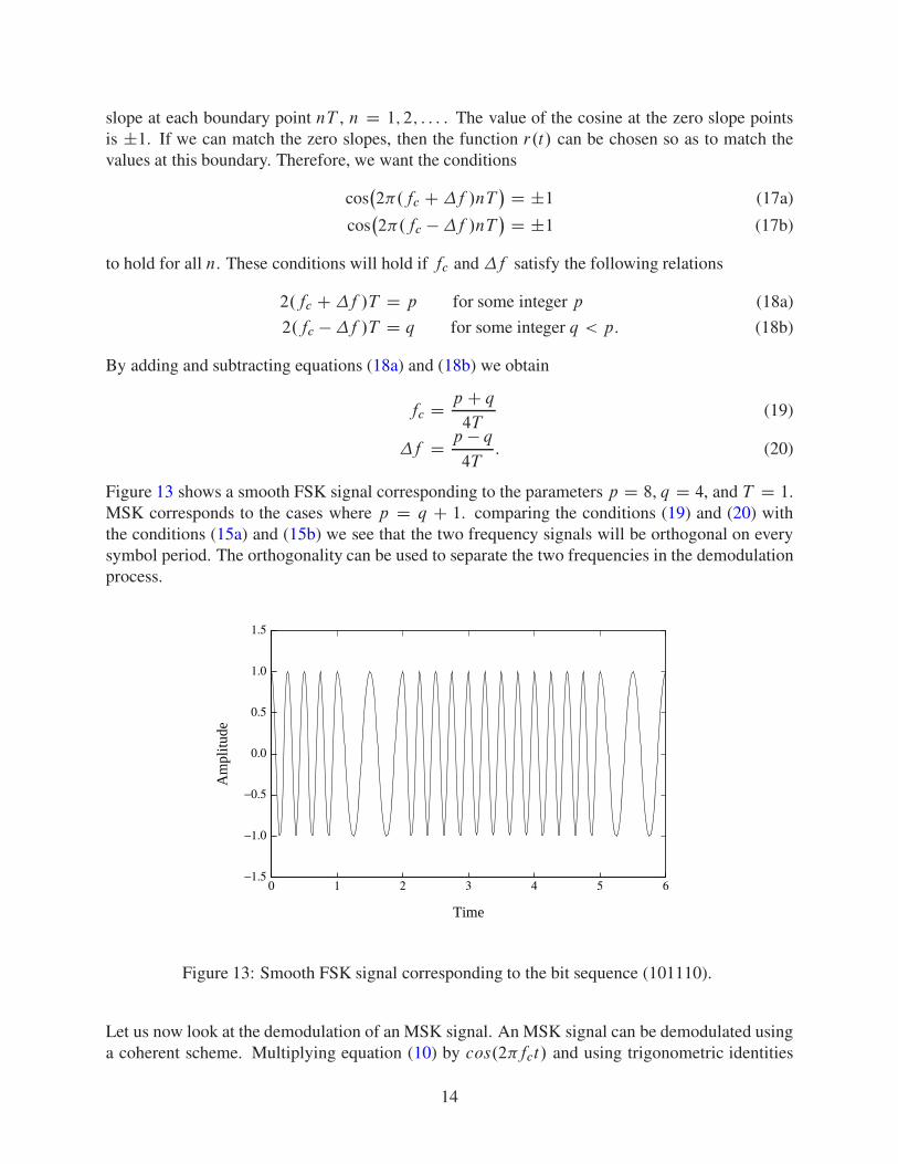
Figure 13 shows a smooth FSK signal corresponding to the parameters p D 8, q D 4, and T D 1.MSK corresponds to the cases where p D q C 1. comparing the conditions (19) and (20) withthe conditions (15a) and (15b) we see that the two frequency signals will be orthogonal on everysymbol period. The orthogonality can be used to separate the two frequencies in the demodulationprocess.
0 1 2 3 4 5 6
Time
−1.5
−1.0
−0.5
0.0
0.5
1.0
1.5
Am
plitu
de
Figure 13: Smooth FSK signal corresponding to the bit sequence (101110).
Let us now look at the demodulation of an MSK signal. An MSK signal can be demodulated usinga coherent scheme. Multiplying equation (10) by cos.2�fct/ and using trigonometric identities
14
for double angles, we get
x.t/ cos.2�fct/ D 12dI .t/ cos
� �t
2T
�Œ1 C cos.4�fct/� C 1
2dQ.t/ sin
� �t
2T
�sin.4�fct/: (21)
Passing x.t/ cos.2�fct/ through a low pass filter, we obtain the signal xc.t/ defined by
xc.t/ D 12dI .t/ cos
� �t
2T
�: (22)
If we now integrate xc.t/ over an interval Œ.2k � 1/T; .2k C 1/T �, we obtain
Z .2kC1/T
.2k�1/T
xc.t/ dt D 12dI .2kT /
2T
�sin
� �t
2T
�ˇ̌ˇ̌.2kC1/T
.2k�1/T
D 2dI .2kT /T
�.�1/k: (23)
From this result we can obtain dI .2kT /.
Similarly, multiplication of equation (10) by sin.2�fct/ yields
x.t/ sin.2�fct/ D 12dI .t/ cos
� �t
2T
�sin.4�fct/ C 1
2dQ.t/ sin
� �t
2T
�Œ1 C cos.4�fct/�: (24)
Passing x.t/ sin.2�fct/ through a low pass filter, we obtain the signal xs.t/ defined by
xs.t/ D 12dQ.t/ sin
� �t
2T
�: (25)
If we now integrate xs.t/ over an interval Œ2kT; .2k C 2/T �, we obtain
Z .2kC2/T
2kT
xs.t/ dt D �12dQ
�.2k C 1/T
�2T
�cos
� �t
2T
�ˇ̌ˇ̌.2kC2/T
2kT
D 2dQ
�.2k C 1/T
�T
�.�1/k:
(26)From this result we can obtain dQ
�.2k C 1/T
�. The original digital sequence can be reconstructed
from the dI and dQ values.
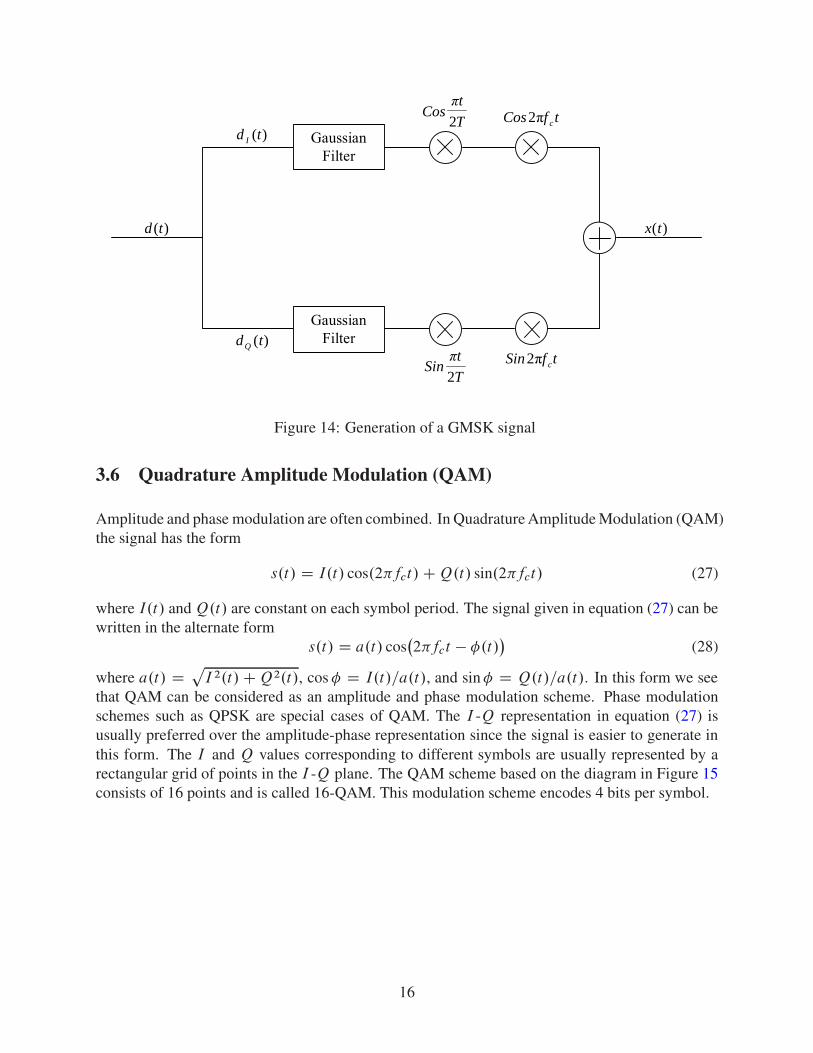
There is a modification of MSK called Gaussian Minimum Shift Keying (GMSK) that is used in anumber of systems. GMSK follows the same process as MSK except that the modulating digitalsignals are smoothed with a Gaussian filter. The process is pictured in Figure 14.
The smoothing decreases the bandwidth and the inter-channel interference, but it increases theinter-symbol interference. The demodulation of a GMSK signal is similar to that used for an MSKsignal. GMSK is used in a number of cellular devices as well as Bluetooth devices for short rangeconnectivity.
15
GaussianFilter
GaussianFilter
)(td I
)(tdQ
)(td )(tx
T
tSin
2
π
T
tCos
2
πtfCos cπ2
tfSin cπ2
Figure 14: Generation of a GMSK signal
3.6 Quadrature Amplitude Modulation (QAM)
Amplitude and phase modulation are often combined. In Quadrature Amplitude Modulation (QAM)the signal has the form
s.t/ D I.t/ cos.2�fct/ C Q.t/ sin.2�fct/ (27)
where I.t/ and Q.t/ are constant on each symbol period. The signal given in equation (27) can bewritten in the alternate form
s.t/ D a.t/ cos�2�fct � �.t/
�(28)
where a.t/ D pI 2.t/ C Q2.t/, cos � D I.t/=a.t/, and sin � D Q.t/=a.t/. In this form we see
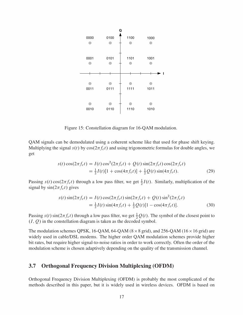
that QAM can be considered as an amplitude and phase modulation scheme. Phase modulationschemes such as QPSK are special cases of QAM. The I -Q representation in equation (27) isusually preferred over the amplitude-phase representation since the signal is easier to generate inthis form. The I and Q values corresponding to different symbols are usually represented by arectangular grid of points in the I -Q plane. The QAM scheme based on the diagram in Figure 15consists of 16 points and is called 16-QAM. This modulation scheme encodes 4 bits per symbol.
16
0000 0100 1100 1000
0001 0101 1101 1001
0011 0111 1111 1011
0010 0110 1110 1010
Q
I
Figure 15: Constellation diagram for 16-QAM modulation.
QAM signals can be demodulated using a coherent scheme like that used for phase shift keying.Multiplying the signal s.t/ by cos.2�fct/ and using trigonometric formulas for double angles, weget
s.t/ cos.2�fct/ D I.t/ cos2.2�fct/ C Q.t/ sin.2�fct/ cos.2�fct/
D 12I.t/Œ1 C cos.4�fct/� C 1
2Q.t/ sin.4�fct/: (29)
Passing s.t/ cos.2�fct/ through a low pass filter, we get 12I.t/. Similarly, multiplication of the
signal by sin.2�fct/ gives
s.t/ sin.2�fct/ D I.t/ cos.2�fct/ sin.2�fct/ C Q.t/ sin2.2�fct/
D 12I.t/ sin.4�fct/ C 1
2Q.t/Œ1 � cos.4�fct/�: (30)
Passing s.t/ sin.2�fct/ through a low pass filter, we get 12Q.t/. The symbol of the closest point to
.I; Q/ in the constellation diagram is taken as the decoded symbol.
The modulation schemes QPSK, 16-QAM, 64-QAM (8 �8 grid), and 256-QAM (16 �16 grid) arewidely used in cable/DSL modems. The higher order QAM modulation schemes provide higherbit rates, but require higher signal-to-noise ratios in order to work correctly. Often the order of themodulation scheme is chosen adaptively depending on the quality of the transmission channel.
3.7 Orthogonal Frequency Division Multiplexing (OFDM)
Orthogonal Frequency Division Multiplexing (OFDM) is probably the most complicated of themethods described in this paper, but it is widely used in wireless devices. OFDM is based on
17
the Discrete Fourier Transform (DFT). For a sequence of complex values x0; x1; : : : ; xN �1 theDiscrete Fourier Transform X0; X1; : : : ; XN �1 of this sequence is defined by
Xn DN �1XmD0
xme�i2�mn=N : (31)
It can be shown that
xm D 1
N
N �1XnD0
Xnei2�mn=N : (32)
This relation is called the inverse DFT. The DFT and inverse DFT can be computed rapidly usingFast Fourier Transform (FFT) algorithms or devices. The sequence fxmg is usually considered tobe in the time domain, and the sequence fXng is usually considered to be in the frequency domain.If T is the symbol period, we can write equations (31) and (32) as follows
x.tm/ D 1
N
N �1XnD0
X.fn/ei2�fntm D xm (33a)
X.fn/ DN �1XmD0
x.tm/e�i2�fntm D Xn (33b)
where tm D m�t , fn D n�f , �t D T=N , and �f D 1=T . Thus, the x.tm/ values can beconsidered as sampled values of the time function x.t/ given by
x.t/ D 1
N
N �1XnD0
X.fn/ei2�fnt : (34)
It can be shown that the functions fei2�fntg are orthogonal over each symbol period, i.e.,
Z .kC1/T
kT
ei2�fmte�i2�fn t dt D 0 m ¤ n: (35)
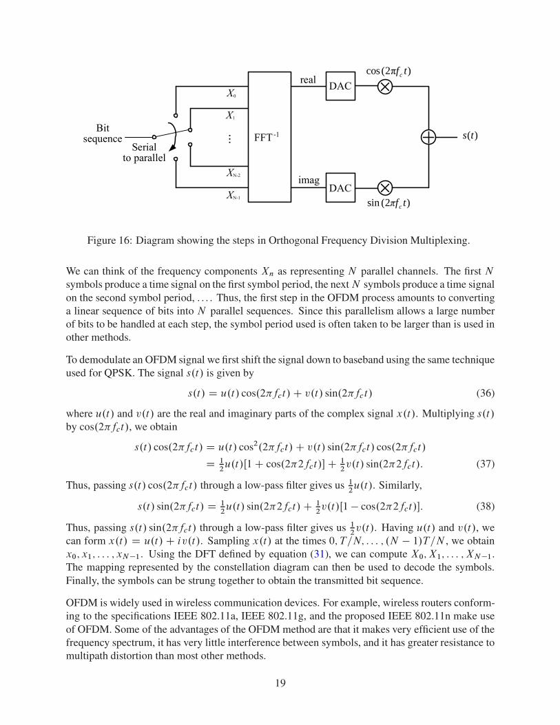
In the OFDM method the symbols are represented by complex values that are then used for thefrequency components Xn in equation (32). The constellation diagrams introduced in connectionwith the PSK and QAM modulation schemes can be looked upon as defining mappings betweensymbols and complex values. Using one of the constellation diagrams we assign the complexnumber corresponding to the first symbol to X0, the complex number corresponding to the secondsymbol to X1, and so on until the complex number corresponding to the N -th symbol is assignedto XN �1. We then obtain a sequence of time values fxmg by means of the inverse DFT definedin equation (32). This sequence is in general complex. The real and imaginary parts of thissequence can be converted to continuous functions of time on the interval T using a digital-to-analog converter (DAC). The real and imaginary functions of time on each symbol period are oftenused to modulate carrier signals cos.2�fct/ and sin.2�fct/ respectively. A diagram of the processis shown in Figure 16.
18
X0
X1
XN-1
XN-2
... FFT-1
Serialto parallel
Bitsequence
DAC
DAC
)(ts
)2(sin tfcπ
)π2(cos tfcreal
imag
Figure 16: Diagram showing the steps in Orthogonal Frequency Division Multiplexing.
We can think of the frequency components Xn as representing N parallel channels. The first N
symbols produce a time signal on the first symbol period, the next N symbols produce a time signalon the second symbol period, . . . . Thus, the first step in the OFDM process amounts to convertinga linear sequence of bits into N parallel sequences. Since this parallelism allows a large numberof bits to be handled at each step, the symbol period used is often taken to be larger than is used inother methods.
To demodulate an OFDM signal we first shift the signal down to baseband using the same techniqueused for QPSK. The signal s.t/ is given by
s.t/ D u.t/ cos.2�fct/ C v.t/ sin.2�fct/ (36)
where u.t/ and v.t/ are the real and imaginary parts of the complex signal x.t/. Multiplying s.t/
by cos.2�fct/, we obtain
s.t/ cos.2�fct/ D u.t/ cos2.2�fct/ C v.t/ sin.2�fct/ cos.2�fct/
D 12u.t/Œ1 C cos.2�2fct/� C 1
2v.t/ sin.2�2fct/: (37)
Thus, passing s.t/ cos.2�fct/ through a low-pass filter gives us 12u.t/. Similarly,
s.t/ sin.2�fct/ D 12u.t/ sin.2�2fct/ C 1
2v.t/Œ1 � cos.2�2fct/�: (38)
Thus, passing s.t/ sin.2�fct/ through a low-pass filter gives us 12v.t/. Having u.t/ and v.t/, we
can form x.t/ D u.t/ C iv.t/. Sampling x.t/ at the times 0; T=N; : : : ; .N � 1/T=N , we obtainx0; x1; : : : ; xN �1. Using the DFT defined by equation (31), we can compute X0; X1; : : : ; XN �1.The mapping represented by the constellation diagram can then be used to decode the symbols.Finally, the symbols can be strung together to obtain the transmitted bit sequence.
OFDM is widely used in wireless communication devices. For example, wireless routers conform-ing to the specifications IEEE 802.11a, IEEE 802.11g, and the proposed IEEE 802.11n make useof OFDM. Some of the advantages of the OFDM method are that it makes very efficient use of thefrequency spectrum, it has very little interference between symbols, and it has greater resistance tomultipath distortion than most other methods.
19
3.8 Frequency Hopping Spread Spectrum (FHSS)
Frequency Hopping Spread Spectrum (FHSS) is a technique used in many wireless devices inorder to spread the transmitted information over a wider frequency band. There are several reasonswhy this spreading is desirable. (1) Spread-spectrum signals are highly resistant to narrow-bandnoise and jamming. (2) Spread-spectrum signals are difficult to intercept. They tend to look likebackground noise. (3) Spread-spectrum signals can share a frequency band with many types ofconventional transmissions with minimal interference.
In FHSS the carrier frequency hops over a predetermined but random-like sequence of frequencies.The pattern of frequency hops must be known by both the transmitter and the receiver. If the periodof the frequency hopping is shorter than the symbol period (fast hopping), then there is a built inredundancy since each symbol will occur in more than one carrier. This redundancy is useful inreducing the effects of narrow band noise and jamming. The main disadvantage to fast hoppingis that coherent detection is difficult and seldom used. If the period of the frequency hopping isgreater than the symbol period (slow hopping), then coherent detection schemes are feasible andthe implementation is easier. The disadvantage of slow hopping is that narrow-band noise candestroy one or more bits of information making error correcting codes almost a necessity. Anyof the techniques discussed previously can be used to modulate the carrier signals. FHSS allowsmultiple devices with different hopping codes to operate simultaneously. Since the hopping patternis random like, this technique offers some security against eavesdropping. Frequency HoppingSpread Spectrum (FHSS) is used in a number of wireless devices including Bluetooth devices.
3.9 Direct-Sequence Spread Spectrum (DSSS)
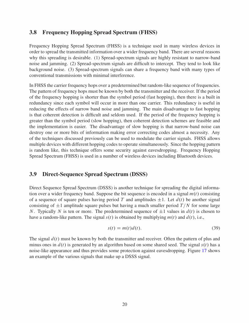
Direct Sequence Spread Spectrum (DSSS) is another technique for spreading the digital informa-tion over a wider frequency band. Suppose the bit sequence is encoded in a signal m.t/ consistingof a sequence of square pulses having period T and amplitudes ˙1. Let d.t/ be another signalconsisting of ˙1 amplitude square pulses but having a much smaller period T=N for some largeN . Typically N is ten or more. The predetermined sequence of ˙1 values in d.t/ is chosen tohave a random-like pattern. The signal s.t/ is obtained by multiplying m.t/ and d.t/, i.e.,
s.t/ D m.t/d.t/: (39)
The signal d.t/ must be known by both the transmitter and receiver. Often the pattern of plus andminus ones in d.t/ is generated by an algorithm based on some shared seed. The signal s.t/ has anoise-like appearance and thus provides some protection against eavesdropping. Figure 17 showsan example of the various signals that make up a DSSS signal.
20
m(t)
d(t)
s(t)
1
-1
1
1
-1
-1
Figure 17: Example of Direct Sequence Spread Spectrum.
Since d.t/ only takes on the values ˙1, multiplying d by itself produces a function that is iden-tically one. Therefore, multiplication of equation (39) by d.t/ gives m.t/ D s.t/d.t/ . Thus,decoding of this process is very simple. There is an inherent redundancy in DSSS that is usefulin overcoming narrow band noise and jamming. Since the resulting signal in DSSS is also digital,this method can also be combined with any of the modulation techniques discussed previously.DSSS is used in a number of wireless applications. For example, wireless routers conformingto the specification IEEE 802.11b use DSSS and wireless routers conforming to the specificationIEEE 802.11g use DSSS and OFDM.
3.9.1 Code Division Multiple Access (CDMA)
Analog cell phones divide the frequency band up into a number of smaller sub bands called chan-nels and assign each user a different channel. Digital cell phones commonly use a technique calledCode Division Multiple Access (CDMA) that allows each user to use the whole frequency band.CDMA is a form of DSSS in which each user is assigned a different pseudo random signal tomultiply the original digital signal. The pseudo random signals assigned to different users are cho-sen so that the correlation between them is small. The DSSS signals are used to modulate a highfrequency carrier. QPSK is often used for this modulation.
21