Embed Size (px)
Citation preview
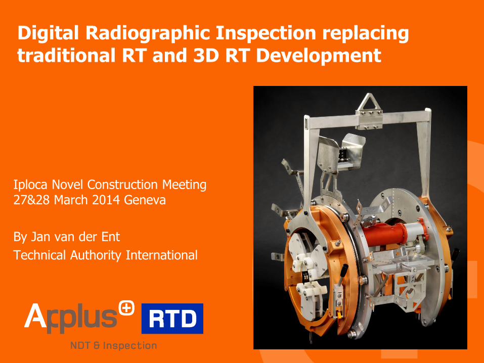
Digital Radiographic Inspection replacing traditional RT and 3D RT Development
Iploca Novel Construction Meeting 27&28 March 2014 Geneva
By Jan van der Ent
Technical Authority International

Contents
Introduction of Digital Radiography
Advantages of digital radiography
Digital Radiography inspection methodology
RTD RAYSCAN system
Digital detector and Image processing principle
Time delayed integration
Image Quality indicator
Software features
Practical benefits of RTD RAYSCAN
Future development, 3D tomography
| 2

Introduction of Digital Radiography
Radiographic image = x-ray image (photography)
RTR = Real Time Radiography = direct x-ray image
| 3

Digital RTR vs. Conventional RT
Advantages of digital vs. conventional RT:
Shorter exposure times (due to high sensitivity)
Reduced angle of radiation beam
Improved radiation safety (lower keV)
Direct on-line weld image display
No residual products lower costs
• No use of chemicals
• No film
Large dynamic range (multiple film classes covered)
| 4

Geometric unsharpness comparison
Image 1 : Poor geometric un-sharpness, high radiation risk!
Image 2 : Multiple exposures, high radiation risk!
Image 3 : RAYSCAN system methodology
– Eliminates geometrical un-sharpness
– Eliminates multiple images
– Reduces the radiation risk
| 5
Panoramic film
Crawler
Directional film
Detector
External source
RAYSCAN METHODOLOGY
IMAGE 1 IMAGE 2 IMAGE 3

Movie Rayscan system
| 6

Digitial RT system development
| 7
2” 12” 16” 20” 24”
Shielded
Unshielded

The heart of the Rayscan: Digital Sensor
Rayscan uses a digital sensor (like a digital photocamera... but for Xrays)
The Xray-photographs are 6mm wide and up to 220mm long
300 photographs (or frames) a second are being made!
Software re-constructs all photographs to a complete weld-image
High efficiency of sensor makes it possible to inspect large wall thicknesses with relative low radiation.
| 8
Active
area

Digital X-ray detector principle
Direct detection of x rays with:
Biased semiconductor
Collection array
X-ray photons hit the semiconductor
X-ray photons generate charges in semiconductor
Field separates charges
Charges are processed by collection array
| 9
Incident
x-ray
photons
Field
electrode Dielectric
layer
Semi-
conductor
Collection array –
(signal to computer)

RTR inspection methodology
DWSI technique used in the RTR system
Tube and detector rotate around the pipe and the data is processed.
After full rotation the whole weld is captured and processed by the software.
| 10
Detector
Tube
Pipe

Time Delayed Integration (TDI)
The detector has to read at least one image when it moves by the width of a pixel.
The (e.g.) seven pixel rows of the detector acquire different parts of the weld (color).
| 11
Detector
Tube
Pipe
1 2 3 4 5 6 7 1 2 3 4 5 6 7
1. frame

Time Delayed Integration (TDI)
The detector moves. For the second acquisition the seven pixel rows cover a new area of the weld, i.e., additionally “mid blue” but not “dark red” anymore)
The pixel rows are shifted by one row.
| 12
Detector
Tube
Pipe
1 2 3 4 5 6 7
1 2 3 4 5 6 7
2. frame
1. frame

Time Delayed Integration (TDI)
After another acquisition the pixel rows are shifted by two with “dark blue” as an additional weld area.
And so forth for all acquisitions!
| 13
Detector
Tube
Pipe
1 2 3 4 5 6 7 1 2 3 4 5 6 7
1 2 3 4 5 6 7
1 2 3 4 5 6 7
3. frame
2. frame
1. frame
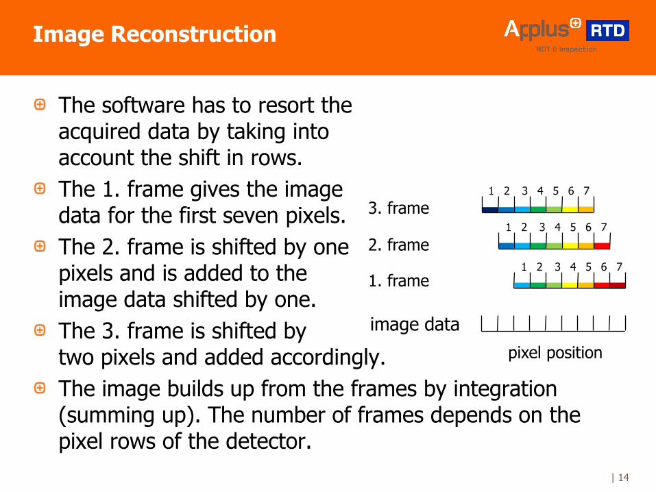
Image Reconstruction
The software has to resort the acquired data by taking into account the shift in rows.
The 1. frame gives the image data for the first seven pixels.
The 2. frame is shifted by one pixels and is added to the image data shifted by one.
The 3. frame is shifted by two pixels and added accordingly.
The image builds up from the frames by integration (summing up). The number of frames depends on the pixel rows of the detector.
| 14
1 2 3 4 5 6 7
1 2 3 4 5 6 7
1 2 3 4 5 6 7
3. frame
2. frame
1. frame
image data
pixel position

RTD RayScan system performance
Minimal motion un-sharpness
No film un-sharpness
Image quality equal or better than film or other digital RT
High performance (using constant potential X-ray ) with lower radiation, see example below;
Conventional directional X ray 300 keV x-ray radiation
Digital CP RT 160 keV x-ray radiation
Noise reduction improved image quality
| 15

Image Quality Indicators (IQI)
| 16
Single wire IQI Double wire IQI (Rayleigh criterion >20%)
According to EN 1435, soon to be accepted ISO 17636 part 1 and 2 (DR)
IQI’s are used to measure sensitivity and spatial resolution
Single : Sensitivity
Double : Spatial resolution

Image Enhancement with RTD RayScan
| 17
Wall Thickness 16mm, 8” CS - 175kV, 4mA
Brightness
Contrast

Digital Zoom with RTD RayScan
| 18
Wall Thickness 16mm, 8” CS - 175kV, 4mA
Cluster porosity Source side IQI –13th wire visible Scattered porosity
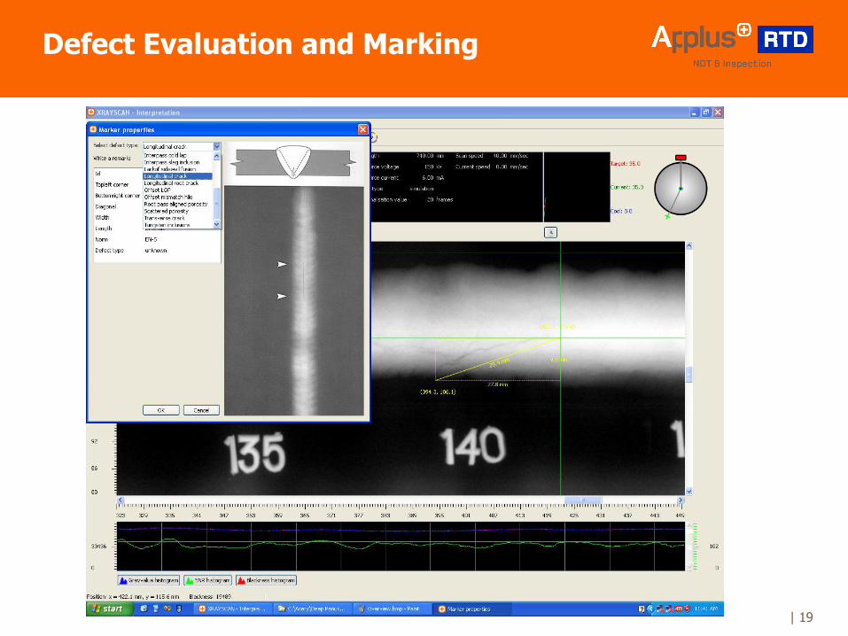
Defect Evaluation and Marking
| 19

Practical Benefits of RTD RayScan
Typical benefits of RTD RAYSCAN
No films or consumables, no storage cabinets required
No darkroom, no processors or chemicals (chemical waste)
No waiting time for film development
Less personnel (scanner tech + operator)
Digital enhancement tools
Lower radiation
Wide range of pipe sizes and wall thickness
However also the Digital radiographic inspection technique, despite the mentioned benefits, is limited to the use of standard workmanship acceptance criteria as no defect height can be measured.
| 20

3D Development: Applus RTD TomoCAR for Accurate Defect Sizing and Characterization
| 21

Why 3D Radiographic Inspection?
Defect orientation
Defects can be missed due to orientation
Position of Source relative to film
Defects can be missed due to orientation
Operator subjective interpretation
Influence of human judgment
Probability of Detection
Is negative influence by above factors
Standard Radiographic
Doesn’t offer defect height sizing
Main objectives are :
• To improve the Probability of Detection
• To introduce ECA based acceptance criteria into the RT
inspection
| 23
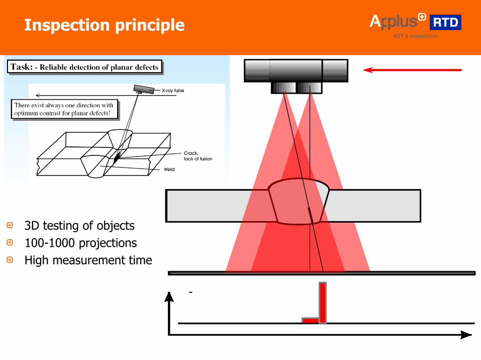
Inspection principle
3D testing of objects
100-1000 projections
High measurement time

Scanning in X direction through weld
| 24
X -scan direction
X
Defect height visible in cross section

| 25
Defect height System Data analysis

| 26
What is more
in the pipeline?
Thank you!
Jan van der Ent
ApplusRTD
Technical Authority Pipeline Department