Embed Size (px)
Citation preview

Digital Radiography
Dr Sangeeta Malik
Reader
Oral Medicine and Radiology

INDEX INTRODUCTION
PRINCIPLES OF DENTAL IMAGING
DIGITAL DETECTORS- CCD
CMOS
CID
PSP
FLAT PANEL DETECTOR
DIGITAL DETECTOR CHARACTERISTICS
CONTRAST RESOLUTION
SPATIAL RESOLUTION
DETECTOR LATITUDE
DETECTOR SENSITIVITY

DIGITAL IMAGE DISPLAY
IMAGE PROCESSING
IMAGE RESTORATION
IMAGE ENHANCEMENT
IMAGE ANALYSIS
IMAGE STORAGE
IMAGE COMPRESSION
OTHER CLINICAL APPLICATIONS BESIDES RADIOGRAPHIC IMAGING
ADVANTAGES
DISADVANTAGES
CONCLUSION

Any method of X-ray image formation that uses a
computer to store and manipulate data is termed as
"Digital Radiography".
Digital imaging offers some distinct advantages over
film, but like any emerging technology, it presents
with new and different challenges for the practitioner
to overcome.

The first direct digital imaging system,
RadioVisioGraphy (RVG), was invented by Dr.
Frances Mouyens for use in dentistry and
manufactured by Trophy Radiologie (Vincennes,
France) in 1987.

Basic elements
1. X-ray machine
2. An electronic sensor or detector
3. An analog to digital converter
4. A computer
5. A monitor

Digital system

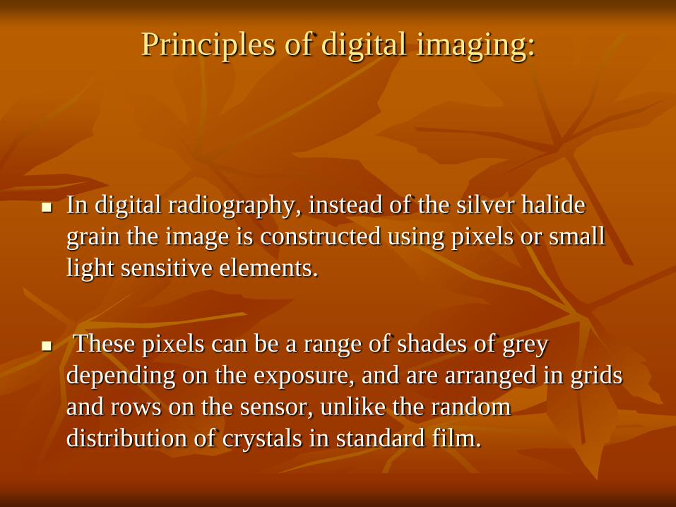
Principles of digital imaging:
In digital radiography, instead of the silver halide
grain the image is constructed using pixels or small
light sensitive elements.
These pixels can be a range of shades of grey
depending on the exposure, and are arranged in grids
and rows on the sensor, unlike the random
distribution of crystals in standard film.


Digital imaging is the result of x-ray interaction with electrons
in electronic sensor pixels (picture elements), conversion of
analog data to digital data, computer processing, and display of
the visible image on a computer screen.

Digital images are numeric and
discrete in two ways:
In terms of the spatial distribution of the picture elements (pixels) and
In terms of different shades of gray of its pixels.

At each pixel of an electronic detector, the absorption of X-rays generates a small voltage.
More x-rays generate higher voltage and vice versa.
At each pixel, the voltage can fluctuate between a minimum and maximum value and is therefore an analog signal.

Analog to digital conversion (ADC).
ADC consists of two steps: sampling and quantization.
Sampling means that small ranges of voltage values are grouped together as a single value. Once sampled, the signal is quantized, which means that every sampled signal is assigned a value.
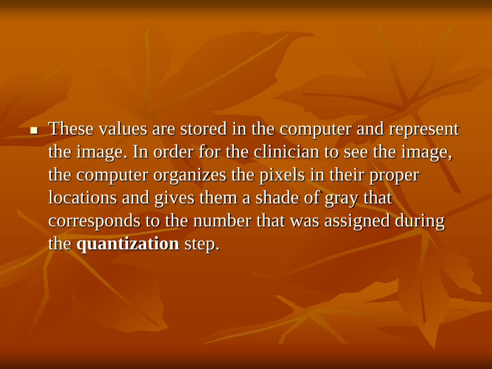
These values are stored in the computer and represent
the image. In order for the clinician to see the image,
the computer organizes the pixels in their proper
locations and gives them a shade of gray that
corresponds to the number that was assigned during
the quantization step.


Three Methods to Obtain a Digital Image
Currently Exist
Direct Digital Imaging: Here a sensor is placed in the
patient's mouth and exposed to radiation. The sensor
captures the radiographic image and then transmits the
image to a computer monitor, and within seconds the
image appears on the computer screen.

Digital system

Indirect Digital Imaging: X-ray film is digitized using a CCD camera, and then displays it on the computer monitor.
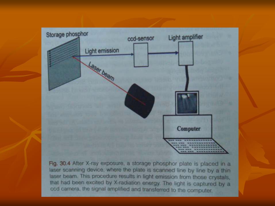
Storage Phosphor Imaging:
- records diagnostic data on the plates following
exposure to the X-ray source
-and uses a high speed scanner to convert the
information to electronic files which can be
displayed on the computer screen.

SENSORS
1.Charged couple device-CCD
2.Complementary metal oxide semiconductor-CMOS
3.Charge injector device- CID
4.Storage phosphor plate- SPP or
Photostimulable phosphor plate-PPP/PSP

FILM & SENSORS

Digital Detectors
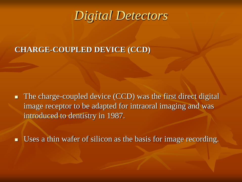
CHARGE-COUPLED DEVICE (CCD)
The charge-coupled device (CCD) was the first direct digital
image receptor to be adapted for intraoral imaging and was
introduced to dentistry in 1987.
Uses a thin wafer of silicon as the basis for image recording.
There are two types of digital sensor array designs.
Area arrays - are used in intraoral radiography (Sizes-0,1,2)
-Fiberoptically coupled sensors- Gadolinium oxybromide
, cesium iodide
-Direct sensors
Linear arrays - are used in extraoral radiography (panoramic
and cephalometric imaging)

Basic structure of the CCD

When exposed to radiation, the covalent bonds between silicon atoms are broken, producing electron-hole pairs
The number of electron-hole pairs that are formed is proportional to the amount of exposure that an area receives.


The image is read by transferring each row of pixel charges from one pixel to the next in a "bucket brigade" fashion.
As a charge reaches the end of its row, it is transferred to a readout amplifier and transmitted as a voltage to the analog-to-digital converter located within or connected to the computer.
Voltages from each pixel are sampled and assigned a numerical value representing a gray level. The silicon matrix and its associated readout and amplifying electronics are enclosed within a plastic housing to protect them from the oral environment.


Most detectors incorporate an electronic cable to transfer data
to the ADC.
One manufacturer has produced a system that replaces the
cable connection with a microwave transmitter. This frees the
detector from a direct tether to the computer, but it necessitates
some additional electronic components, thus increasing the
overall bulk of the sensor.

COMPLEMENTARY METAL OXIDE
SEMICONDUCTOR (CMOS)
These detectors are silicon-based semiconductors but
are fundamentally different from CCDs in the way
that pixel charges are read.
Each pixel is isolated from its neighboring pixels and
is directly connected to a transistor. Like the CCD,
electron hole pairs are generated within the pixel in
proportion to the amount of x-ray energy that is
absorbed.

This charge is transferred to the transistor as a small
voltage. The voltage in each transistor can be
addressed separately, read by the frame grabber, and
then stored and displayed as a digital gray value.

Charge Injection Device (CID):
Charge Injection Device (CID): is another sensor technology, structurally it is very much like the CCD, but in this case no computer is required to process the images.
This system consists of a CID X-ray sensor, cord and plug that can be inserted into the light source on the camera platform, digital images are seen on the system monitor within seconds.
The CID sensor uses the same docking platform as the intraoral camera. The image can be printed with a color video printer and saved as a computer file or onto a video desk recorder.

Photostimulable Phosphor Plates (PSP)
The photostimulator phosphor used for
radiographic imaging is Europium doped, barium
fluorohalide. Barium in combination with iodine,
chlorine, or bromine forms a crystal lattice.

These absorb and store energy from X-rays
and then release this energy as light
(phosphorescence) when stimulated by other
light of appropriate wavelength

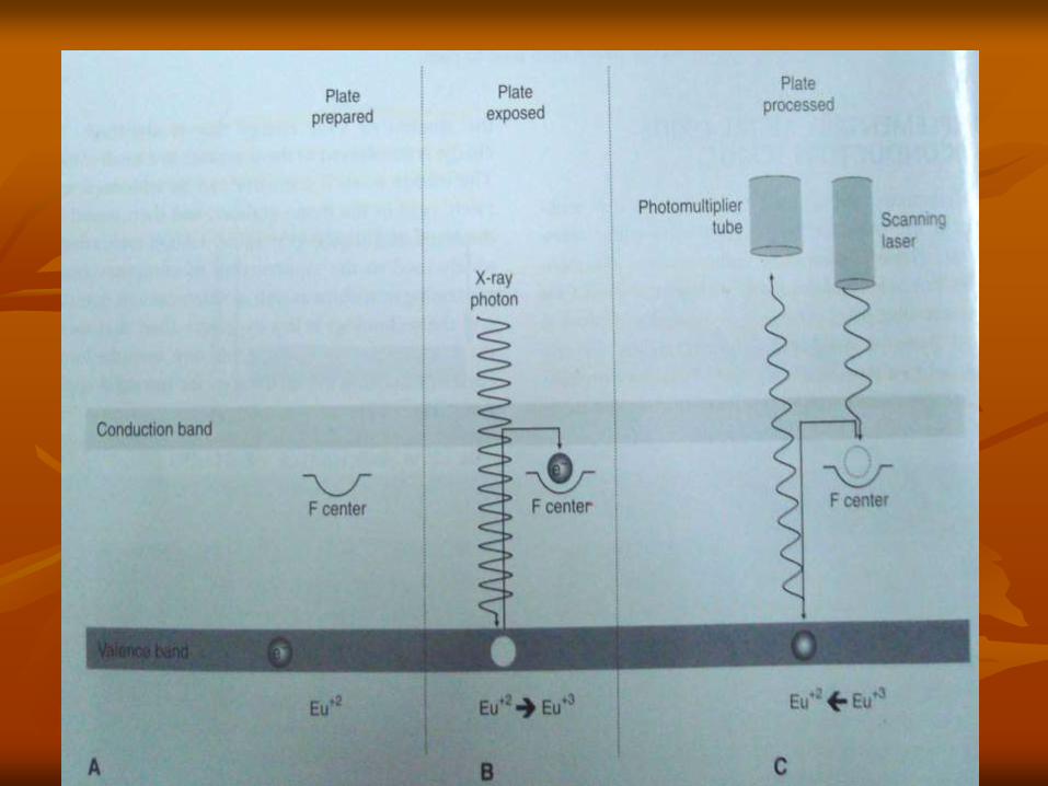
When exposed to radiation, valence electrons in Europium can absorb energy and move into the conduction band.
These electrons migrate to nearby halogen vacancies in the fluorohalide lattice and may become trapped there in a metastable state.
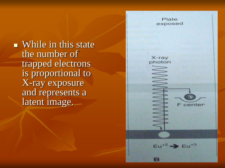
While in this state the number of trapped electrons is proportional to X-ray exposure and represents a latent image.

When stimulated by red light of around 600 nm, the barium fluorohalide releases trapped electrons to the conduction band.
When an electron returns to the Europium ion, energy is released in the green spectrum between 300 and 500 nm.
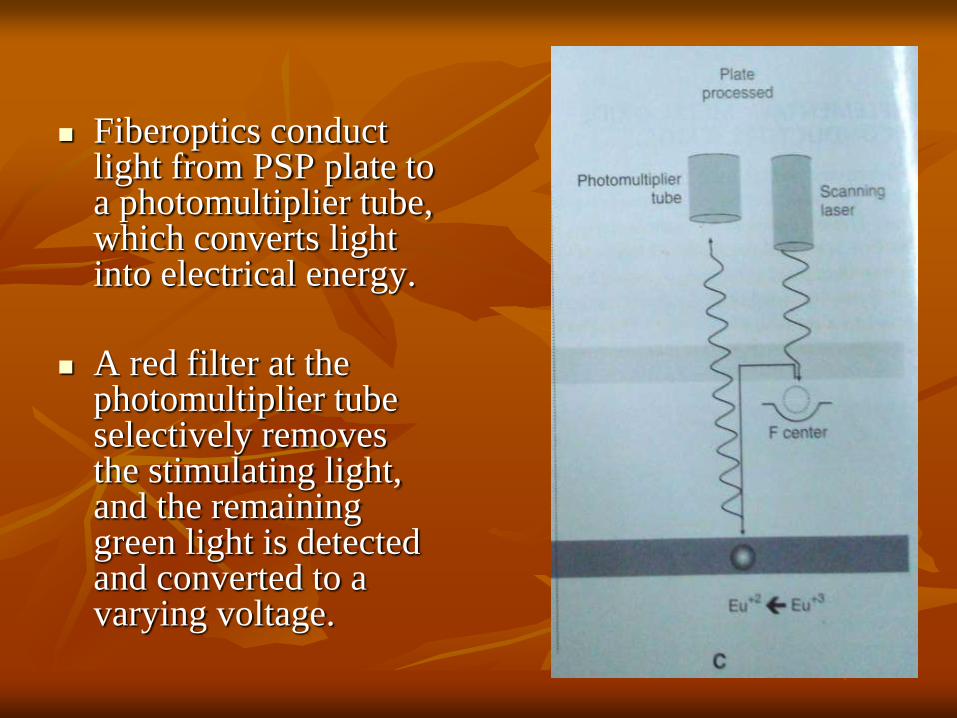
Fiberoptics conduct light from PSP plate to a photomultiplier tube, which converts light into electrical energy.
A red filter at the photomultiplier tube selectively removes the stimulating light, and the remaining green light is detected and converted to a varying voltage.

The variation in the voltage output from the photomultiplier tube corresponds to variations in stimulated light intensity from the latent image.
The voltage signal is quantified by an analog-to-digital converter and stored and displayed as a digital image.
PSP plates are made in sizes similar to intraoral films, and sizes commonly used for panoramic and cephalometric imaging.

Before PSP is used the plates must be erased to eliminate 'ghost images' from prior exposures.
Following exposure, plates should be processed as soon as possible, as the trapped electrons are spontaneously released over a period of time.
The latent image can be read by:
Stationary plate scans
Rotating plate scans

The active (tube side) surface of the plate (left) and plate placed in the
infection control pouch (right). The plate is oriented with the
tube side against the black (opaque) side of the pouch to limit exposure of the
active side of the plate to ambient light.

Storage phosphor sensors

The drum on which storage phosphor plates are clipped. The drum is inserted
into the scanner and the lid is closed before scanning
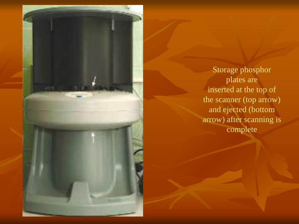
Storage phosphor
plates are
inserted at the top of
the scanner (top arrow)
and ejected (bottom
arrow) after scanning is
complete

Flat Panel Detectors
These provide a relatively large matrix areas with pixel sizes less than 100 microns.
This allows direct digital imaging of larger areas of the body, including the head. These are of two types: Indirect detectors that are sensitive to visible light, and an intensifying screen is used to convert X-ray photons to light.
Direct detectors which used a photoconductor material (selenium) with properties similar to silicon and a higher atomic number that permits more efficient absorption of X-rays.

Digital detector characteristics
Contrast resolution
Spatial resolution
Detector latitude
Detector sensitivity
Contrast resolution- is ability to distinguish different
densities in radiographic image.
Spatial resolution- is for distinguishing fine detail. The
theoretical limit of resolution is function of picture element
(pixel) size for digital imaging system. Currently, the highest
resolution CCD detector for dentistry have pixel sizes of
approx 20 microns. Current digital systems are capable of
providing more than 71p/mm of resolution.

Detector latitude- The ability of a detector to capture a range of x-ray exposure is termed latitude. The latitude of CCD and CMOS detectors is similar to film. PSP have larger latitude.
Detector sensitivity-is its ability to respond to small amount of radiation. It depends upon detector efficiency, pixel size, system noise.
Current PSP systems for intraoral imaging allow dose reductions of about 50% in comparison with F-speed film. High resolution CCD and CMOS systems achieve less dose reduction than lower resolution PSP systems.
CCD and PSP systems for extra-oral imaging require exposures similar to those needed for 200-speed screen-film systems.

Digital Image Display
Cathode Ray Tube (CRT) which are used in
conventional computer monitors.
Thin Film Transistor (TFT) is used in laptop
and flat panel computer displays.

The image may be:
i. Stored permanently in the computer.
ii. Printed on a hard copy for patient record.
a.Film printer.
b Paper printer.
iii. Transmitted electronically to insurance companies or
referring dental specialists.

Display & print out of image

The computer offers Split screen technology: which allows the
operator to view and compare multiple images on the same
screen. This helps in the comparison and evaluation of disease
progression and treatment results.
IMAGE PROCESSING
Digital image processing operations can be grouped into five
fundamental classes:
Restoration
Image enhancement
Analysis
Compression
synthesis.

i. Image restoration: defects in the raw data
received are corrected before the image
becomes visible on screen.

ii. Image enhancement:
Most image enhancement operations are applied to make the image visually more appealing. This is done by adjusting the:
a. Brightness and contrast;
Digital radiographs do not always effectively utilize the full range of available gray values. They can be relatively dark or light, and they can show too much contrast in certain areas or not enough.
This can be modified by changing the display of the image without changing the image.

b)Sharpening and smoothening.
The purpose of sharpening and smoothing filters is to improve image quality by removing blur or noise.
Noise is often categorized as high-frequency noise (speckling) or low-frequency noise (gradual intensity changes).
Filters that smooth an image are sometimes called despeckling filters because they remove high-frequency noise.
Filters that sharpen an image either remove low-frequency noise or enhance boundaries between regions with different intensities (edge enhancement).
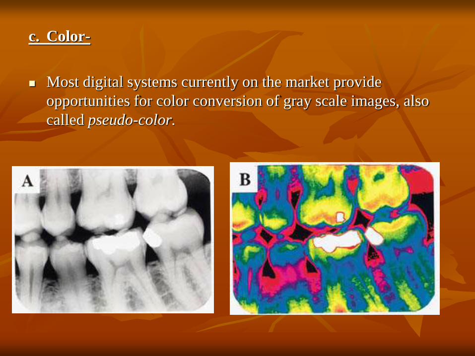
c. Color-
Most digital systems currently on the market provide
opportunities for color conversion of gray scale images, also
called pseudo-color.

d) Digital Subtraction Radiography (DSR):
This is a specialized digital technique in which two digital radiographic
images (with an interval) of the same region made by standardized method
are made & then the two images are superimposed.
Special software is used to subtract the regions that are unchanged and
thereby highlighting those regions where there is a difference.
With conventional radiography it is impossible to detect an 0.85 mm
changed in cortical bone thickness but DSR is so sensitive it can detect
0.12 mm change.
DSR can be used in periodontal and carious lesions. For evaluation of small
changes in mandibular condyle position and integritiy of the articular
surface and for assessment of osseous remodeling around granular
hydroxyapatite implants.

Digital Subtraction Radiography (DSR):
The subtraction of Figures 1a and b reveals
areas of bone loss in black (black arrow) and
bone deposition in white (white arrows).
After extraction 1 month later subtraction of Figures 1a
and b reveals areas of bone loss
in black (black arrow) and bone
deposition in white (white arrows).

iii. Image analysis:
These operations are designed to extract nonpictorial information
from image that is diagnostically relevant.
Magnification, this allows better viewing and linear and
angular measurements can also be obtained, e.g. for measuring
root length.
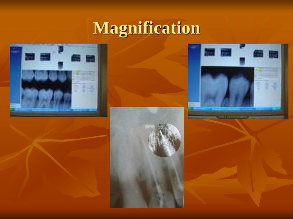
Magnification


iv. Image Compression:
Here the image is compressed by reducing the number of
digital image files for storage or transmission.
Lossless methods do not discard any image data, and an exact
copy of the image is reproduced after decompression.
Lossy compression methods achieve higher levels of
compression by discarding image data.

Version 3.0 of the DICOM (Digital Imaging and
Communications in Medicine) standard adopted JPEG (Joint
Photographic Experts Group) as the compression method,
which provides a range of compression levels.

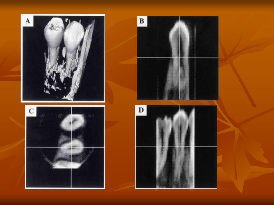
v. Image Synthesis:
Synthesizing new images based upon image data acquired
from multiple projections.
The purpose of these modalities is to access information about
the object of interest in three dimensions.
CT, MRI and Positron Emission Tomography Scanners are
amongst the most well known and sophisticated image
synthesizers for maxillofacial imaging.

Digital imaging is used in several techniques-
Intraoral radiography
Panoramic radiography
Cephalometry
C.T.
MRI

Other Clinical Applications besides
Radiographic Imaging
1. Microscopic Imaging
Medical grade single frame digital cameras are available which
may be attached to dental microscopes, and produce high
quality images.
2. Intraoral Cameras
These are dental cameras that can photograph a single tooth, a
group of teeth or a patient's full face.
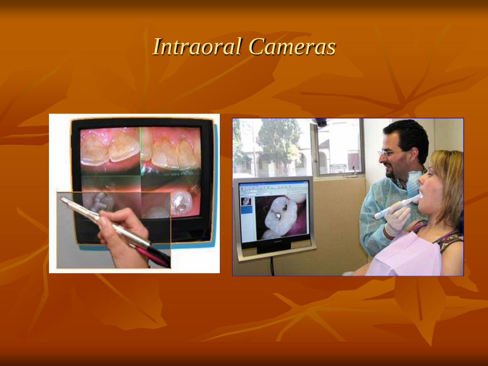
Intraoral Cameras

3.Fiberoptic Imaging
Fiberoptic endoscopes specifically for use in the oral cavity,
to view the root canals. This consists of a 0.7 mm and 11.8
mm diameter light fiberoptic probe, the former can be
inserted into the root canal for internal viewing.
4. Digital Photography
Inexpensive and records the images with a high degree of
accuracy. These have a better resolution, accurate color
values and no occurance of ghosting or distortion.

Advantages
Reduced exposure to X-radiation-may be reduced by 50-90%
per intraoral exposure.
Increased speed or faster image acquisition
Enhancement of diagnostic image
Image reconstruction-Digital images may be reconstructed to
provide insight into the anatomy of internal structures, display
cross-sectional views, and produce multi-dimensional views

Image storage-Paperless file
Effective patient education tool
Envioronmental friendly
Teleradiography

Disadvantages
Initial set-up is costly.
Image quality
Fragility of sensors
Wire attached to sensor
Sensor size-these are thicker and rigid than intraoral
films and therefore not patient compliant.

Infection control, the sensor has to be covered adequately in a
disposable plastic wrapper.
Legal issues, because the original digital image can be
manipulated, it is debatable whether digital radiographs
can be used as evidence in lawsuits

Conclusion
DR is an excellent alternative to film-based radiography and continues to grow in popularity.
Images can be taken, immediately examined, deleted, corrected, and subsequently sent to a network of computers.
The benefits from digital radiology are enormous. It can make the facility filmless.
The referring physician can view the requested image on a desktop personal computer, often with the report, just minutes after the examination was performed.
The images are no longer held in a single location; they can be seen simultaneously by physicians who are kilometres apart.
In addition, the patient can have all his or her X rays on a compact disk to take to another physician or hospital.
Thus digital radiography will soon become a standard in dentistry as well as in medical radiology.

References
White , Pharoah. Digital Imaging. In: Oral Radiology-Principles and Interpretation. 5th ed,ch-12.Mosby;2006:225-244.
Freny R. Kajodkar. Digital Radiography. In: textbook of dental and Maxillofacial Radiology.Ch-15.Jaypee Brothers Medical Publishers (P) Ltd ;2006:259-266
Haring , Howerton . Digital Radiography. In: Dental Radiography: Principles and Techniques.3rd ed,ch 24. Saunders;2006: 344-354 .
Gerard C.H. Sanderink, Dale A Miles.Intraoral Detectors CCD,CMOS,TFT and other devices.Dental clinics of North America.April 2000;44(2):249-255
J. Brennan.An introduction to digital radiography in Dentistry.Journal of orthodontics,2002;29:66-69.

THANK-YOU