Embed Size (px)
Citation preview

4 OCTOBER 2004, GSA TODAY
GSA Today; v. 14; no. 10, doi: 10.1130/1052-5173(2004)014<4:DFSAPC>2.0.CO;2
Dilational fault slip and pit chain formation on MarsDavid A. Ferrill and Danielle Y. Wyrick, CNWRA, Southwest Research Institute, 6220 Culebra Road, San Antonio, Texas 78238, USA, [email protected]
Alan P. Morris, Department of Earth and Environmental Science, University of Texas, San Antonio, Texas 78249, USA
Darrell W. Sims and Nathan M. Franklin, CNWRA, Southwest Research Institute, 6220 Culebra Road, San Antonio, Texas 78238, USA
ABSTRACTPit crater chains that are parallel or
collinear with normal faults are com-mon on Mars, but only rarely observed on Earth. We explore the origin of pit crater chains using recent high-resolu-tion imagery from Mars, laboratory simulation of pit chains, investigation of recent pit chains formed in response to seismic fault slip in Iceland, and as-sessment of rock failure criteria and the Martian crustal stress field to develop a deeper understanding of the relation-ship between pit chain formation and fault activity. Based on these analyses, we conclude that pit chains form in re-sponse to dilational fault slip. Because gravitational acceleration on Earth (9.81 m/s2) is higher than on Mars (3.72 m/s2), stress within Earth is greater than that of Mars for any given depth. Consequently, steep fault segments are likely to extend to about 5 km depth on Mars compared with about 2 km depth on Earth. Dilation of these steep segments associated with fault slip on Mars could result in large volume increase in the uppermost crust, influencing groundwater flow and dis-charge and mineralization. Based on crosscutting relationships, pristine pit morphologies, and lack of evidence of sediment accumulation in the bottoms of pits, we interpret that some pit craters may be actively forming in response to dilational fault slip.
Figure 1. (A) Composite Viking imagery of normal fault scarps defining horsts and grabens in the southeast part of Alba Patera, Mars. Fault segmentation and en echelon arrangement of faults and grabens are common. Scale bar is 50 km. (B) THEMIS visible spectrum image shows detail of normal faults and pit chain (Phlegethon Catena) shown in A. Scale bar is 5 km. (C) Mars Orbital Camera image shows clear association of pit chains with normal fault scarps within graben on the southeast flank of Alba Patera. Scale bar is 1 km.

GSA TODAY, OCTOBER 2004 5
INTRODUCTIONThe surface of Mars has been a source of debate since
the earliest telescopic observations in the 1600s by Galileo, Huygens, and Cassini. Unprecedented detail in images and topographic maps generated by Mars missions within the past three decades allows identification of features carved by flow-ing water (Carr, 1996), accumulations of wind-blown sand and active dust devils (Malin and Edgett, 2001), and landforms generated by tectonic faulting (Schultz, 1985; Anderson et al., 2001; Wilkins and Schultz, 2003). Views of strata exposed in walls of canyons and pits demonstrate the presence of rock layers with different strengths (McEwen et al., 1999), dispelling the belief that the Martian surface has been so heavily dam-aged by impact cratering that it consists primarily of cohesion-less regolith (Tanaka and Golombek, 1989).
Comparisons of geologic features on Mars with analogous features on Earth have been used extensively to understand Martian crustal processes. One distinctive feature of Martian topography is the occurrence of pit craters and pit chains (Tanaka and Golombek, 1989; Banerdt et al., 1992). Pit craters lack a raised crater rim or ejecta deposits, form alignments (chains), and are likely the result of collapse of loose surface material into a subsurface void (see Wyrick et al., 2004, and references therein). The close association of pit crater chains with faulting on Mars (Tanaka and Golombek, 1989; Wyrick et al., 2004) indicates that some Martian faults produce consider-able subsurface void space. Collapse features seen on Earth are neither as widespread nor as large as those seen on Mars, nor is the mechanism of widespread dissolution of soluble rock, such as limestone or evaporites, observed on Earth likely on Mars. High-resolution imagery reveals that many pit craters have conical shapes. In addition, the walls of pit cra-ters, troughs, grabens, and erosional canyons display a near-horizontal stratigraphy, composed of alternating layers with relatively low (gentle slopes) and relatively high (steep slopes) mechanical strength. The extreme size of pit craters on Mars, with diameters of individual pits reaching >4 km, and pit vol-umes >7 km3 (Wyrick et al., 2004), has remained an enigma.
Using recent high-resolution imagery from Mars, labora-tory simulation of pit chains, investigation of recent pit chains formed in response to seismic fault slip in Iceland, and assess-ment of rock failure criteria and the Martian crustal stress field, we explore the origin of pit crater chains. We conclude that pit chains form in response to fault slip and dilation, consistent with the interpretation of active faulting on Mars (Anderson et al., 2001).
FAULT-LOCALIZED PIT CHAINS ON ALBA PATERA, MARS
Alba Patera is a large shield volcano, measuring 2700 km across, in the northern part of the Tharsis region on Mars (Cailleau et al., 2003). Normal faulting of Alba Patera is thought to have been active between the onset of the Noachian through the Early Amazonian—possibly more than a billion years of activity (Cailleau et al., 2003). Normal faults gener-ally strike NNE-SSW through Alba Patera, but are tangential or locally circumferential to the volcano on the east, west, and northwest flanks of the volcano. Normal faults and associated horsts and grabens (fossae) locally host pit crater chains on
Figure 2. Schematic illustrations of faulting on Mars that display steep dilated faults and their potential relationship to pit chain development. (A) Pit chain and trough localized along the surface traces of dilational faults (compare with Fig. 1C). (B) Pit chain in surface graben in unconsolidated material above a dilational fault at depth (compare with Fig. 1A and B).
the eastern (Phlegethon Catenae, Archeron Catenae, Tractus Catenae) and western (Alba Catenae, Cyane Catenae, and Artynia Catenae) flanks of Alba Patera.
Images from Viking (e.g., Fig. 1A), Thermal Emission Imaging System (THEMIS; Fig. 1B), and Mars Orbital Camera (MOC; Fig. 1C) show the clear association of pit chains with normal faults, and the Phlegethon Catenae pit chain system displays the association of pits with a graben. Within a graben, pits and troughs tend to be localized along surface fault traces (Fig. 1C). The clear isolated pits in Fig. 1B are along a portion of Phlegethon Catenae where associated faults have relatively small displacements. Northeast and southwest of the area of Fig. 1B (see Fig. 1A) displacement increases laterally along the graben bounding faults and the pit chain has developed into a trough along the fault scarps. In the narrow-angle MOC im-age shown in Fig. 1C, pits are localized along a fault scarp with 100 m throw (based on Mars Orbiter Laser Altimeter, or MOLA, data). In the same figure, the fault with 600 m throw hosts a trough that we interpret to have developed from coalescence of a pit chain along the fault trace (Fig. 2A). The association of normal faults and pit chains (Fig. 2) implies that pit chains are surface indicators of normal faults which in turn influence
6 OCTOBER 2004, GSA TODAY
hydrothermal circulation, groundwater hydrology, and seismicity.
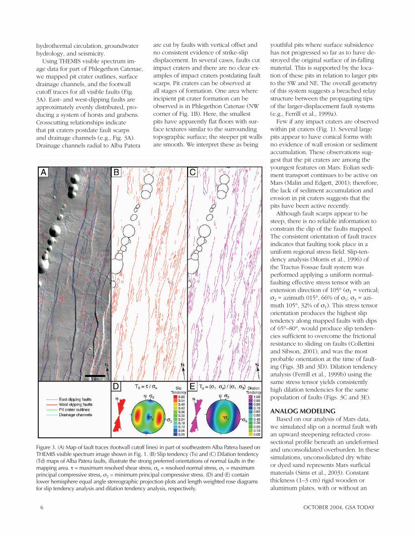
Using THEMIS visible spectrum im-age data for part of Phlegethon Catenae, we mapped pit crater outlines, surface drainage channels, and the footwall cutoff traces for all visible faults (Fig. 3A). East- and west-dipping faults are approximately evenly distributed, pro-ducing a system of horsts and grabens. Crosscutting relationships indicate that pit craters postdate fault scarps and drainage channels (e.g., Fig. 3A). Drainage channels radial to Alba Patera
are cut by faults with vertical offset and no consistent evidence of strike-slip displacement. In several cases, faults cut impact craters and there are no clear ex-amples of impact craters postdating fault scarps. Pit craters can be observed at all stages of formation. One area where incipient pit crater formation can be observed is in Phlegethon Catenae (NW corner of Fig. 1B). Here, the smallest pits have apparently flat floors with sur-face textures similar to the surrounding topographic surface; the steeper pit walls are smooth. We interpret these as being
youthful pits where surface subsidence has not progressed so far as to have de-stroyed the original surface of in-falling material. This is supported by the loca-tion of these pits in relation to larger pits to the SW and NE. The overall geometry of this system suggests a breached relay structure between the propagating tips of the larger-displacement fault systems (e.g., Ferrill et al., 1999a).
Few if any impact craters are observed within pit craters (Fig. 1). Several large pits appear to have conical forms with no evidence of wall erosion or sediment accumulation. These observations sug-gest that the pit craters are among the youngest features on Mars. Eolian sedi-ment transport continues to be active on Mars (Malin and Edgett, 2001); therefore, the lack of sediment accumulation and erosion in pit craters suggests that the pits have been active recently.
Although fault scarps appear to be steep, there is no reliable information to constrain the dip of the faults mapped. The consistent orientation of fault traces indicates that faulting took place in a uniform regional stress field. Slip-ten-dency analysis (Morris et al., 1996) of the Tractus Fossae fault system was performed applying a uniform normal-faulting effective stress tensor with an extension direction of 105° (σ1 = vertical; σ2 = azimuth 015°, 66% of σ1; σ3 = azi-muth 105°, 32% of σ1). This stress tensor orientation produces the highest slip tendency along mapped faults with dips of 65°–80°, would produce slip tenden-cies sufficient to overcome the frictional resistance to sliding on faults (Collettini and Sibson, 2001), and was the most probable orientation at the time of fault-ing (Figs. 3B and 3D). Dilation tendency analysis (Ferrill et al., 1999b) using the same stress tensor yields consistently high dilation tendencies for the same population of faults (Figs. 3C and 3E).
ANALOG MODELINGBased on our analysis of Mars data,
we simulated slip on a normal fault with an upward steepening refracted cross- sectional profile beneath an undeformed and unconsolidated overburden. In these simulations, unconsolidated dry white or dyed sand represents Mars surficial materials (Sims et al., 2003). Constant thickness (1–3 cm) rigid wooden or aluminum plates, with or without an
Figure 3. (A) Map of fault traces (footwall cutoff lines) in part of southeastern Alba Patera based on THEMIS visible spectrum image shown in Fig. 1. (B) Slip tendency (Ts) and (C) Dilation tendency (Td) maps of Alba Patera faults, illustrate the strong preferred orientations of normal faults in the mapping area. τ = maximum resolved shear stress, σn = resolved normal stress, σ1 = maximum principal compressive stress, σ3 = minimum principal compressive stress. (D) and (E) contain lower hemisphere equal angle stereographic projection plots and length weighted rose diagrams for slip tendency analysis and dilation tendency analysis, respectively.

GSA TODAY, OCTOBER 2004 7
overlying layer of cohesive powder, were used to represent dilating fissures beneath the surficial material. Two fault geometries with imposed displacements were used to simulate fault geometry at depth: (a) a vertical upper fault segment linked to a horizontal detachment at depth (Sims et al., 2003), and (b) a verti-cal fault segment linked to a fault with
65° dip (consistent with slip tendency analysis) at depth (Fig. 4A). Plates were initially edge-to-edge, and tabular voids were created by progressively separating the plates. In some experiments, a layer of cohesive powder, capable of sup-porting steep to near vertical walls, was used in combination with rigid plates to represent the refracted fault geometries.
Fault traces were slightly irregular or cor-rugated (Ferrill et al., 1999a), similar to faults observed on Earth and Mars.
Most pit chain morphologies observed on Mars, including (i) chains of isolated circular or irregularly shaped pits, (ii) elongate pits, (iii) pit chains grading to troughs along trace, and (iv) pit chains along graben bounding faults (Wyrick et al., 2004), were reproduced in our physi-cal models. Modeled pit chains follow a uniform developmental sequence from an alignment of circular pits of varying size, and variable (Sims et al., 2003) or regular (Horstman and Melosh, 1989) spacings, to elongate pits, to coalesced pits that form continuous troughs. Different stages of development were often present simultaneously along fault strike (e.g., Fig. 4H). Model pit chains tend to form somewhat irregular map traces, even where formed over paral-lel rigid plates. In some experiments, pit formation was preceded or accompanied by the formation of elongate grabens (Sims et al., 2003), with pit formation usually occurring along a single bound-ing fault.
In Model 19NOV03b (Fig. 4), displace-ment was gradually applied along the 65° fault segment at depth and produced oblique dilation of a vertical fault seg-ment beneath a layer of cohesive pow-der. Overlying the cohesive powder was a layer of dry sand. As displacement pro-gressed, an extension fracture propa-gated upward through the cohesive
Figure 4. Analog modeling example of normal faulting and pit chain development. Model 19NOV03b produced a pit chain in unconsolidated sand above a refracted normal fault. (A) Schematic cross section illustrating model setup for simulation of pit chain development in a sandpack resting on a layer of relatively cohesive silica powder above a refracted normal fault that is vertical at the top and dips 65° at depth. Imposed displacement is normal dip slip along the 65° fault segment. The vertical fault segment experiences oblique dilation parallel to the slip vector on the 65° fault segment at depth. (B) Oblique photograph illustrating model pit chain development along the surface rupture trace of the normal fault. (C–H) Plan view photographs (illumination is from the top in each photo) of the model surface during progressive displacement, D, of the underlying normal fault.

8 OCTOBER 2004, GSA TODAY
Figure 5 (here and on facing page). Pit chains in northeastern Iceland. (A) Shallow grabens and pit chain in gravels overlying basalt near the north coast of Iceland (inset map of Iceland shows the extent of the mid-Atlantic Ridge, and dot shows location of photograph near Ásbyrgi). Grabens and pit chains developed in response to an extensional deformation event in December 1975. Photograph was taken by George McGill on July 3, 1976. View is to the north. Note person (Bran Potter) standing in pit. (B) Aerial photograph taken on September 5, 1958, shows no evidence of pit chains and only subtle evidence of faulting. (C) Aerial photograph on September 2, 1976, shows pit chains. (D) Aerial photograph taken on August 3, 1984, shows growth and development of several pits between 1976 and 1984. Also during the 1976–1984 period, a stream channel established itself along one pit chain (trough), and subsequent erosion and deposition progressively erased the surface expression of the pit chain along the stream’s course.
powder layer and progressively dilated. The void space filled by draining of the overlying unconsolidated dry sand (Fig. 4), producing pits up to 1 cm diameter in the sand. Initially isolated pits gradu-ally grew and intersected, forming elon-gate pits, scalloped sided coalesced pits, and relatively smooth-sided troughs (Figs. 4C–4H).
PIT CRATER CHAINS IN ICELANDAlthough pit crater chains are com-
mon on Mars, comparable examples on Earth are rare (Wyrick et al., 2004). A striking example of pit chain devel-opment occurred in Iceland during the rifting episode that started in 1975. December 20, 1975, marked the begin-ning of a rifting and subsidence episode along the Mid-Atlantic spreading center
in northeastern Iceland. This first event, the largest event of the deformation episode, continued into February 1976 and was followed by 10 more events from September 1976 to May 1979 (Sigurdsson, 1980). Deformation events were marked by seismicity, small-vol-ume volcanic eruptions at Krafla (during first, fifth, and sixth events), reactivation of faults along existing surface traces, and the formation of normal fault scarps, grabens, and pit crater chains in allu-vium where surface ruptures were previ-ously unmapped. Seismicity and ground surface fissures associated with the December 1975 through February 1976 event were concentrated in a NNE-SSW–trending elongate region extending 30–50 km north of the Krafla caldera center. Surface ruptures with components of
dilation and normal dip slip (Opheim and Gudmundsson, 1989; Angelier et al., 1997; Dauteuil et al., 2001) formed along previously mapped fault traces in basalt flows. To the north, a 1–1.25-km wide and 12-km-long system of fault ruptures, fissures, and pit craters also formed in the floodplain deposits of Jökulsá á Fjöllum (Sigurdsson, 1980). In alluvium of the Jökulsá plain, within 2 km north of the contact with the gently northward-dipping basalt flows, the nor-mal fault system reactivated by the first event produced a 1-km-wide graben that accommodated an estimated 1.5 m of horizontal extension and approximately 1 m vertical throw. The western graben-bounding fault system accommodated approximately 30 cm horizontal exten-sion and 1 m vertical throw.
George McGill provided us with the ground photograph of a pit crater chain formed within this western graben-bounding fault system in the floodplain deposits of Jökulsá á Fjöllum during the December 1975 through February 1976 event (Fig. 5A). Aerial photographs taken on (1) September 5, 1958, (2) September 2, 1976, and (3) August 3, 1984, of the same region document the formation and evolution of this pit crater chain (Fig. 5). The photograph taken on September 5, 1958, (Fig. 5B) shows no evidence of pit chains and only subtle evidence of faulting. The aerial photo-graph taken on September 2, 1976,

GSA TODAY, OCTOBER 2004 9
(Fig. 5C) shows pit chains that trend NNE-SSW and consist of pits ranging in size from ~1 m to ~10 m in diameter. Some pit chains are clearly associated with normal faults, in some cases occur-ring within a down-dropped graben be-tween two normal fault scarps. Aerial photographs taken on August 3, 1984, show growth of numerous pits between 1976 and 1984. Also during the 1976–1984 period, a stream channel estab-lished itself along one pit chain (trough), and subsequent erosion and deposition progressively erased the surface expres-sion of the pit chain along the stream’s course. Aerial photographs taken after August 3, 1984, show some growth of
pits and minor change in the amount of erasure of pits by the stream erosion and deposition.
Although the pit crater chains formed during this crustal deformation episode in Iceland are small, generally <10 m diameter, they are excellent geologic analogs for pit craters observed on Mars. Faults along the Icelandic rift have dilational displacement (Opheim and Gudmundsson, 1989; Angelier et al., 1997; Dauteuil et al., 2001) and this is likely the result of the contrast in strength between basalt and interbedded ash and sediment (Ferrill and Morris, 2003). Where dilational jogs occur be-neath unconsolidated surface material,
they cause subsidence of this material into fault-generated void space and hence pit crater formation. We interpret their small size to be due to the thin layer of unconsolidated surficial deposits overlying the basalt and a small void volume formed by 10 cm to 2 m fault displacements. In Iceland, pit crater vol-umes represent a short series of events and rapid sedimentation fills the pit crater before the next deformation event (Fig. 5D).
WHY ARE PIT CRATERS SO LARGE AND SO EVIDENT ON MARS?
On Mars, where erosion is minimal, pit size may represent a cumulative

10 OCTOBER 2004, GSA TODAY
Figure 6. (A) Mohr circle and illustration of tensile, hybrid, shear failure modes (after Ferrill and Morris, 2003). (B) Lithostatic stress gradients on Earth vs. Mars assuming same rock type (basalts) and no hydrostatic gradient. (C) Hoek-Brown failure envelopes for basalt, color coded according to fault dips for the normal faulting regime, comparing depths of occurrence in Earth (green) versus Mars (red).
volume as a result of many events spread out over time. On Earth, erosional and depositional processes may erase and/or subdue the surface expression of pit cra-ters within decadal time scales. Although surface processes such as wind and me-teorite impacts can erase pits, these pro-cesses are less effective than flowing wa-ter, which is the dominant erosive agent on Earth. Aerial photography from Iceland (Fig. 5) demonstrates the impor-tant role of erosion and deposition in the obliteration of terrestrial pit craters. Perhaps more important, the influence of Martian gravity on faulting in the brit-tle crust plays a major role in the overall geometry of Martian faults. Martian grav-ity at 3.72 m/s2 is substantially less than Earth’s gravity at 9.81 m/s2 (Table I in Esposito et al., 1992) and this influence, along with rock density, controls the lithostatic stress profile, which is the pri-mary influence on failure characteristics of rock at depth.
FAILURE MODES, NORMAL FAULT PROFILES, AND GRAVITY
Active normal faults on Earth com-monly have steep dips near the surface and progressively more gentle dips at depth (Walsh and Watterson 1988). Dips of 70°–90° are common in the uppermost brittle crust (0–2 km) in a variety of rocks including volcanic tuffs (Day et al., 1998), basalts (Opheim and Gudmundsson, 1989; Angelier et al., 1997; Dauteuil et al., 2001), limestones
(Ferrill and Morris, 2003; Ferrill et al., 2004), and clastic sedimentary rocks (Walsh and Watterson, 1988). Dips of 60° are common at depths of 2–5 km, and dips of 35°–55° are common in the lower part of the brittle crust (>5 km; Jackson and White, 1989; Collettini and Sibson, 2001). Dips of 0°–35° are as-sociated with detachments at the brittle-ductile transition in the crust and in ex-tremely weak sedimentary layers.
Fault orientation in rock is initially controlled by mechanical properties of the faulted rocks, and magnitudes and orientations of the effective principal stresses at the time of failure. Failure angle is the angle between the failure plane and the maximum principal com-pressive stress at the time of failure. The angle of shear failure (θ) in rock can be calculated from the angle of internal fric-tion (friction angle, φ) using:
θ = ± (45° − φ/2) (1)
Failure mode depends on the differen-tial stress (Δσ = σ1 – σ3; where σ1 = max-imum principal compressive stress, and σ3 = minimum principal compressive stress) and the effective minimum princi-pal compressive stress (σ3ʹ; σ3ʹ = σ3 – Pf, where Pf = pore fluid pressure) at the time of failure, and upon the strength characteristics of the rock (e.g., Mandl, 1988 and references therein; Fig. 6A). There are three types of failure (Mandl, 1988; Ferrill and Morris, 2003). Shear
failure is characterized by a failure angle given by Equation (1), displacement parallel to the fracture surface, and the effective normal stress (σnʹ) acting on the fracture surface, σ3ʹ < σnʹ ≥ 0 (Fig. 6A). Tensile failure is characterized by a failure angle of 0° and displacement perpendicular to the fracture surface (Fig. 6A). In this case σ3ʹ = σnʹ < 0 and |σ3ʹ| ≥ tensile strength of the rock. Hybrid failure is characterized by a failure angle between 0° and the angle calculated by Equation (1), and displace-ment oblique to the fracture surface (“dilatant faults,” Mandl, 1988; Fig. 6A). Hybrid fracture, hypothesized and de-bated for decades, has recently been demonstrated in laboratory experiments (Ramsey and Chester, 2004). In the case of hybrid failure, σ3ʹ < σnʹ < 0 and |σ3ʹ| < tensile strength of the rock.
The normal faulting regime is de-fined by a vertical maximum principal compressive stress (Anderson, 1951). The vertical or lithostatic stress (σv) in-creases with depth and is a function of the thickness (h) of the overburden, the integrated density of the overburden (ρ), and the acceleration due to gravity (g):
σv = ρgh (2)
As a result of the vertical stress gradient, differential stress required for failure also increases with depth. Assuming a range of density values of 2.7–3.1 g/cm3 for basalt (Carmichael, 1989) as examples,

GSA TODAY, OCTOBER 2004 11
lithostatic stresses can be calculated as a function of depth for Earth (g = 9.81 m/s2), and Mars (g = 3.72 m/s2) (Fig. 6B). Hoek-Brown failure envelopes (Hoek and Brown, 1988; Schultz and Zuber, 1994) were constructed for an average basalt and two end-member basalts based on failure test data from 37 basalts (Gevantman, 1982). Basalt was chosen as a likely rock type on Mars because extensive volcanic plains cover half of its surface (Gornitz, 1997). Each point on a failure envelope represents a unique value for Δσ, and because the envelopes are nonlinear (especially at low values of Δσ), each point also represents a unique value of the failure angle. Because Δσ for failure is depth-related, and ignor-ing the effects of pore fluid pressure, the envelope curves can be color-coded for normal fault dip (normal fault dip = 90° – failure angle) and correlated with depth in the crust for both Mars and Earth (Fig. 6C). Tensile and hybrid failure for an “average basalt” and corre-sponding fault dips of 78°–90°, would be limited to <2 km on Earth, but are likely to depths of ~5 km on Mars.
Fault profiles on Mars are likely to be similar in shape to analogs on Earth, but depth-dependent fault dip transi-tions are likely to occur deeper than on Earth and occur more gradually with depth. The seismogenic depth associated with extensional deformation on Mars is expected to be shifted deeper due to lower gravity, but would also depend on geothermal gradient at the time of active faulting. Dilational faulting, found in the upper ~2 km on Earth, may extend to depths of 5 km or more on Mars due to the factor of 2.64 difference in gravity.
DISCUSSIONThe common occurrence of pit crater
chains on Mars compared with Earth is probably controlled by two factors: weathering and erosion rates and fault-ing style. Earth’s surface is reworked much more rapidly than that of Mars because of the thicker terrestrial atmo-sphere and the prevalence of surface and near surface water. Pit crater chains formed in Iceland have been signifi-cantly modified and even obliterated within a decade of formation. Martian pit craters are larger by at least an order of magnitude than any on Earth. This size difference has three likely sources: (i)
thickness of low-cohesion surface mate-rial, (ii) depth-extent of the dilational fault segment generating the subsurface void, and (iii) Martian pit craters repre-sent a cumulative volume over a number of faulting events, whereas on Earth, pit crater volume represents a single event. Normal faults and extension fractures on Mars are more likely to be dilatant and extend to greater depths than similar features on Earth because of the lower Martian gravity and consequent lower stress gradient.
Martian thermal history may also have influenced the prevalence of dilational faults. Mars has cooled and conse-quently the thickness of the Martian cryosphere and the thickness of ice in the cryosphere has increased over time (Clifford and Parker, 2001). At a latitude of 30–40°N on Mars today (e.g., Alba Patera examples in Fig. 1), the top of ice is estimated to be at a depth of 10 m (Fanale et al., 1986) and extend to a depth of 3.5–5 km (Clifford and Parker, 2001). The strength of unconsolidated material increases as freezing occurs (p. 272 in Sowers, 1979), therefore steepen-ing the failure envelope. Consequently, the shear failure angle decreases and the stress range over which hybrid failure can occur increases, resulting in steeper dips for faults forming in a frozen strati-graphic section. Deeply frozen rock and unconsolidated materials (Carr, 1996; Clifford and Parker, 2001) would gener-ate deeper, steeper dilatant fault seg-ments. This effect on faulting would be more pronounced as the planet cooled.
Faults and fractures form important pathways for and barriers to groundwa-ter flow on Earth (e.g., Ferrill et al., 2004, and references therein). We anticipate a similar relationship between these features and past groundwater flow on Mars. The occurrence of dilational fault-ing on Mars indicates highly permeable zones and potentially important sites for storage of water or ice and locations of mineralization. Pit chains indicate the presence (either now or formerly) of subsurface voids and potential con-duits for groundwater flow, whether unfilled or filled with porous material. Understanding their mechanism(s) of formation is essential for constraining volumes and locations (depth and lateral extent) of groundwater flow conduits and potential areas of water storage,
with major implications for the subsur-face distribution and movement of water and mineralization in the Martian crust. Recent description of outflow channels sourced by pits supports the interpreta-tion of pit chains as indicators of impor-tant groundwater flow and discharge pathways (Dinwiddie et al., 2004). This interpretation is also consistent with outflow channels sourced by fractures (see summary in table IV of Clifford and Parker, 2001).
CONCLUSIONSMany pit crater chains on Mars are
produced by dilational normal faulting. Pit craters are larger and better preserved on Mars than on Earth because of more active erosion and deposition on Earth and the lower gravity and greater vertical extent of the zone of dilational faulting on Mars. In many areas, pit crater chains appear to be some of the youngest features, postdating drainage channels, faulting, and impact craters. Based on crosscutting relationships, pristine pit morphologies, and lack of evidence of sediment accumulation in pits, we believe that some pit craters may be ac-tively forming. Dilational faults, whether partially filled or open cavities, are likely to have served as conduits for past groundwater flow and would now serve as reservoirs for water or ice.
ACKNOWLEDGMENTSThis work was funded by Southwest
Research Institute through the Internal Research and Development Program (project #R9314). George McGill brought to our attention the occurrence of pit chains in Iceland and was gracious in allowing us to use his field photograph. Shannon Colton assisted with MOC and Viking data preparation, Clark Chapman provided consultation on ages of Martian landscapes, and Bob Grimm provided consultation on the Martian cryosphere and hydrology. Larry McKague and John Russell improved this paper by their constructive reviews. We appreciate the assistance of Cheryl Patton in prepara-tion of the manuscript. Comments by re-viewers Robert Anderson, James Dohm, Jay Melosh, Gerry Ross, Richard Schultz, and Glen Stockmal further improved the manuscript.

12 OCTOBER 2004, GSA TODAY
REFERENCES CITEDAnderson, E.M., 1951, The dynamics of faulting and dyke formation with applications to Britain: Edinburgh, United Kingdom, Oliver and Boyd, 206 p.
Anderson, R.C., Dohm, J.M., Golombek, M.P., Haldemann, A.F.C., Franklin, B.J., Tanaka, K.L., Lias, J., and Peer, B., 2001, Primary centers and secondary concentrations of tectonic activity through time in the western hemisphere of Mars: Journal of Geophysical Research, v. 106, no. E9, p. 20,563–20,585, doi: 10.1029/2000JE001278.
Angelier, J., Bergerat, F., Dauteuil, O., and Villemin, T., 1997, Effective tension-shear relationships in extensional fissure swarms, axial rift zone of northeastern Iceland: Journal of Structural Geology, v. 19, p. 673–685, doi: 10.1016/S0191-8141(96)00106-X.
Banerdt, W.B., Golombek, M.P., and Tanaka, K.L., 1992, Stress and Tectonics on Mars, in Kieffer, H.H., et al., eds., Mars: The University of Arizona Press, p. 249–297.
Cailleau, B., Walter, T.R., Janle, P., and Hauber, E., 2003, Modeling volcanic deformation in a regional stress field: Implications for the formation of graben structures on Alba Patera, Mars: Journal of Geophysical Research, v. 108, no. E12, 5141, doi: 10.1029/2003JE002135.
Carmichael, R.S., 1989, Practical Handbook of Physical Properties of Rocks and Minerals: CRC Press, Boca Raton, Florida.
Carr, M.H., 1996, Water on Mars: New York, Oxford University Press, p. 229.
Clifford, S.M., and Parker, T.J., 2001, The evolution of the Martian hydrosphere: Implications for the fate of a pri-mordial ocean and the current state of the northern plains: Icarus, v. 154, p. 40–79, doi: 10.1006/ICAR.2001.6671.
Collettini, C., and Sibson, R.H., 2001, Normal faults, normal friction?: Geology, v. 29, p. 927–930, doi: 10.1130/0091-7613(2001)0292.0.CO;2.
Dauteuil, O., Angelier, J., Bergerat, F., Verrier, S., and Villemin, T., 2001, Deformation partitioning inside a fis-sure swarm of the northern Iceland rift: Journal of Structural Geology, v. 23, p. 1359–1372, doi: 10.1016/S0191-8141(01)00002-5.
Day, W.C., Dickerson, R.P., Potter, C.J., Sweetkind, D.S., San Juan, C.A., Drake, R.M., II, and Fridrich, C.J., 1998, Bedrock geologic map of the Yucca Mountain area, Nye County, Nevada: U.S. Geological Survey Miscellaneous Investigations Series Map I-2627, Scale 1:24,000.
Dinwiddie, C.L., Coleman, N.M., and Necsoiu, M., 2004, Walla Walla Vallis and Wallula Crater: Two recently dis-covered Martian features record aqueous history: Lunar and Planetary Science Conference 35, Lunar and Planetary Institute, no. 1316.
Esposito, P.B., Banerdt, W.B., Lindal, G.F., Sjogren, W.L., Slade, M.A., Bills, B.G., Smith, D.E., and Balmino, G., 1992, Gravity and topography, in Kieffer, H.H., et al., eds., Mars: The University of Arizona Press, p. 209–248.
Fanale, F.P., Salvail, J.R., Zent, A.P., and Postawko, S.E., 1986, Global distribution and migration of subsurface ice on Mars: Icarus, v. 67, p. 1–18, doi: 10.1016/0019-1035(86)90170-3.
Ferrill, D.A., and Morris, A.P., 2003, Dilational normal faults: Journal of Structural Geology, v. 25, p. 183–196, doi: 10.1016/S0191-8141(02)00029-9.
Ferrill, D.A., Stamatakos, J.A., and Sims, D.W., 1999a, Normal fault corrugation: implications for growth and seismicity of active normal faults: Journal of Structural Geology, v. 21, p. 1027–1038, doi: 10.1016/S0191-8141(99)00017-6.
Ferrill, D.A., Winterle, J., Wittmeyer, G., Sims, D., Colton, S., Armstrong, A., and Morris, A.P., 1999b, Stressed rock strains groundwater at Yucca Mountain, Nevada: GSA Today, v. 9, no. 5, p. 1–8.
Ferrill, D.A., Sims, D.W., Waiting, D.J., Morris, A.P., Franklin, N., and Schultz, A.L., 2004, Structural framework of the Edwards Aquifer recharge zone in south-central Texas: Geological Society of America Bulletin, v. 116, p. 407–418, doi: 10.1130/B25174.1.
Gevantman, L.H., 1982, Physical properties data for ba-salt: U.S. Department of Commerce, National Bureau of Standards, National Measurement Laboratory, Office of Standard Reference Data, Washington, D.C. 20234, Report NBSIR 82-2587.
Gornitz, V., 1997, Mars: Geology, in Shirley, J.H., and Fairbridge, R.W., eds., Encyclopedia of Planetary Sciences: Dordrecht, The Netherlands, Kluwer Academic Publishers, p. 441–450.
Hoek, E., and Brown, E.T., 1988, The Hoek-Brown failure criterion—A 1988 update: 15th Canadian Rock Mechanics Symposium, p. 31–38.
Horstman, C., and Melosh, H.J., 1989, Drainage pits in co-hesionless materials: Implications for the surface of Phobos: Journal of Geophysical Research, v. 94, p. 12433–12441.
Jackson, J.A., and White, N.J., 1989, Normal faulting in the upper continental crust: Observations from regions of active extension: Journal of Structural Geology, v. 11, p. 15–36, doi: 10.1016/0191-8141(89)90033-3.
Mandl, G., 1988, Mechanics of Tectonic Faulting: Elsevier, New York, 407 p.
Malin, M.C., and Edgett, K.S., 2001, Mars Global Surveyor Mars Orbiter Camera: Interplanetary cruise through primary mission: Journal of Geophysical Research, v. 106, no. E10, p. 23,429–23,570, doi: 10.1029/2000JE001455.
McEwen, A.S., Malin, M.C., Carr, M.H., and Hartmann, W.K., 1999, Voluminous volcanism on early Mars revealed in Valles Marineris: Nature, v. 397, p. 584–586, doi: 10.1038/17539.
Morris, A.P., Ferrill, D.A., and Henderson, D.B., 1996, Slip tendency analysis and fault reactivation: Geology, v. 24, p. 275–278, doi: 10.1130/0091-7613(1996)0242.3.CO;2.
Opheim, J.A., and Gudmundsson, A., 1989, Formation and geometry of fractures, and related volcanism, of the Krafla fissure swarm, northeast Iceland: Geological Society of America Bulletin, v. 101, p. 1608–1622, doi: 10.1130/0016-7606(1989)1012.3.CO;2.
Ramsey, J.M., and Chester, F.M., 2004, Hybrid fracture and the transition from extension fracture to shear fracture: Nature, v. 428, p. 63–66, doi: 10.1038/NATURE02333.
Schultz, R.A., 1985, Assessment of global and regional tectonic models for faulting in the ancient terrains of Mars: Journal of Geophysical Research, v. 90, p. 7849–7860.
Schultz, R.A., and Zuber, M.T., 1994, Observations, mod-els, and mechanisms of failure of surface rocks surrounding planetary surface loads: Journal of Geophysical Research, v. 99, no. E7, p. 14691–14702, doi: 10.1029/94JE01140.
Sigurdsson, O., 1980, Surface deformation of the Krafla fissure swarm in two rifting events: Journal of Geophysics, v. 47, p. 154–159.
Sims, D.W., Morris, A.P., Ferrill, D.A., Wyrick, D.Y., and Colton, S.L., 2003, Physical Models of Pit Chain Formation over Dilational Faults on Mars: Lunar and Planetary Science Conference 34, Lunar and Planetary Institute, no. 2099.
Sowers, G.F., 1979, Introductory Soil Mechanics and Foundations: Geotechnical Engineering: New York, MacMillan Publishing Co., Inc., 621 p.
Tanaka, K.L., and Golombek, M.P., 1989, Martian tension fractures and the formation of grabens and collapse features at Valles Marineris: Proceedings of the 19th Lunar and Planetary Science, Conference Lunar and Planetary Science Institute, p. 383–396.
Walsh, J.J., and Watterson, J., 1988, Dips of normal faults in British Coal Measures and other sedimentary se-quences: Journal of the Geological Society, London, v. 145, p. 859–873.
Wilkins, S.J., and Schultz, R.A., 2003, Cross faults in exten-sional settings: Stress triggering, displacement localization, and implications for the origin of blunt troughs at Valles Marineris, Mars: Journal of Geophysical Research, v. 108, no. E6, p. 5056, doi: 10.1029/2002JE001968.
Wyrick, D.Y., Ferrill, D.A., Morris, A.P., Colton, S.L., and Sims, D.W., 2004, Distribution, morphology and origins of Martian pit crater chains: Journal of Geophysical Research, Planets, v. 109, E06005, doi: 10.1029/2004JE002240.
Manuscript received May 11, 2004; accepted July 13, 2004.


![Telecommunication Products - Trendtek jointing pits.pdf · [01] UG2006 - P6 Pit UG2007 - P7 Pit UG2008 - P8 Pit UG2900 - P9 Pit UG2001 - P1 Pit UG2002 - P2 Pit UG2003 - P3 Pit UG2004](https://img.pdfslide.net/doc/110x75/5a7969077f8b9ab9308d3433/telecommunication-products-jointing-pitspdf01-ug2006-p6-pit-ug2007-p7-pit.jpg)