Embed Size (px)
Citation preview
1 of 6 Updated: 3/22/11 12:59 PM This document is available electronically at http://crit.artic.edu/aoc/
The Advanced Output Center Sullivan Center, 36 S Wabash Rm. 1232
312 629 6688 / [email protected]
Guide for File Prep and Submission
Dimension SST 3D Printer
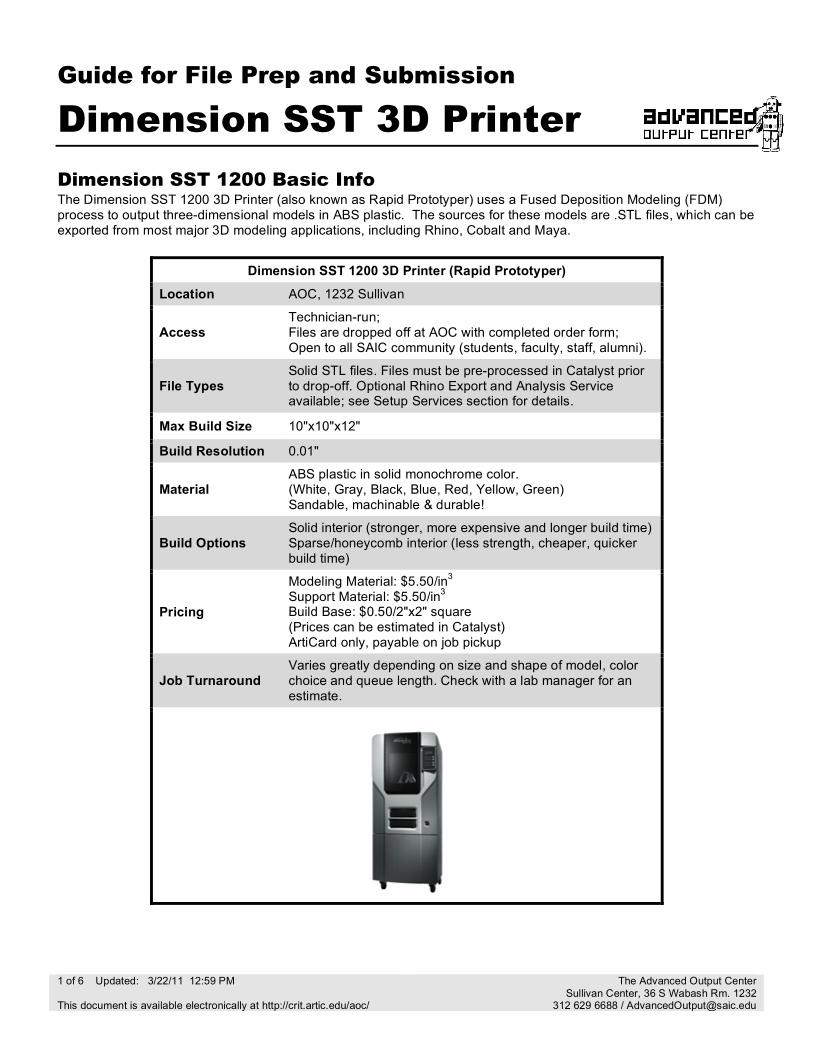
Dimension SST 1200 Basic Info The Dimension SST 1200 3D Printer (also known as Rapid Prototyper) uses a Fused Deposition Modeling (FDM) process to output three-dimensional models in ABS plastic. The sources for these models are .STL files, which can be exported from most major 3D modeling applications, including Rhino, Cobalt and Maya.
Dimension SST 1200 3D Printer (Rapid Prototyper)
Location AOC, 1232 Sullivan
Access Technician-run; Files are dropped off at AOC with completed order form; Open to all SAIC community (students, faculty, staff, alumni).
File Types Solid STL files. Files must be pre-processed in Catalyst prior to drop-off. Optional Rhino Export and Analysis Service available; see Setup Services section for details.
Max Build Size 10"x10"x12"
Build Resolution 0.01"
Material ABS plastic in solid monochrome color. (White, Gray, Black, Blue, Red, Yellow, Green) Sandable, machinable & durable!
Build Options Solid interior (stronger, more expensive and longer build time) Sparse/honeycomb interior (less strength, cheaper, quicker build time)
Pricing
Modeling Material: $5.50/in3 Support Material: $5.50/in3
Build Base: $0.50/2"x2" square (Prices can be estimated in Catalyst) ArtiCard only, payable on job pickup
Job Turnaround Varies greatly depending on size and shape of model, color choice and queue length. Check with a lab manager for an estimate.
2 of 6 Updated: 3/22/11 12:59 PM This document is available electronically at http://crit.artic.edu/aoc/
The Advanced Output Center Sullivan Center, 36 S Wabash Rm. 1232
312 629 6688 / [email protected]
Model Preparation in Rhino These instructions assume a basic working knowledge of modeling in Rhino. If you are unsure about your modeling skill, we recommend that you work with a faculty member who can guide you through the modeling process. You can also visit the AOC’s website for links to helpful tutorials (see the URL at the bottom of this page). Remember, modeling is a skill; it can take months and even years of practice to become proficient!
Units We recommend modeling in either inches or millimeters, especially if accuracy of size is important to your part. The units you use during modeling must correspond to the actual units used during output. To set the units, click on ‘File -> Properties…’ then click on ‘Units.’ Set the ‘Model Units:’ to either inches or millimeters.
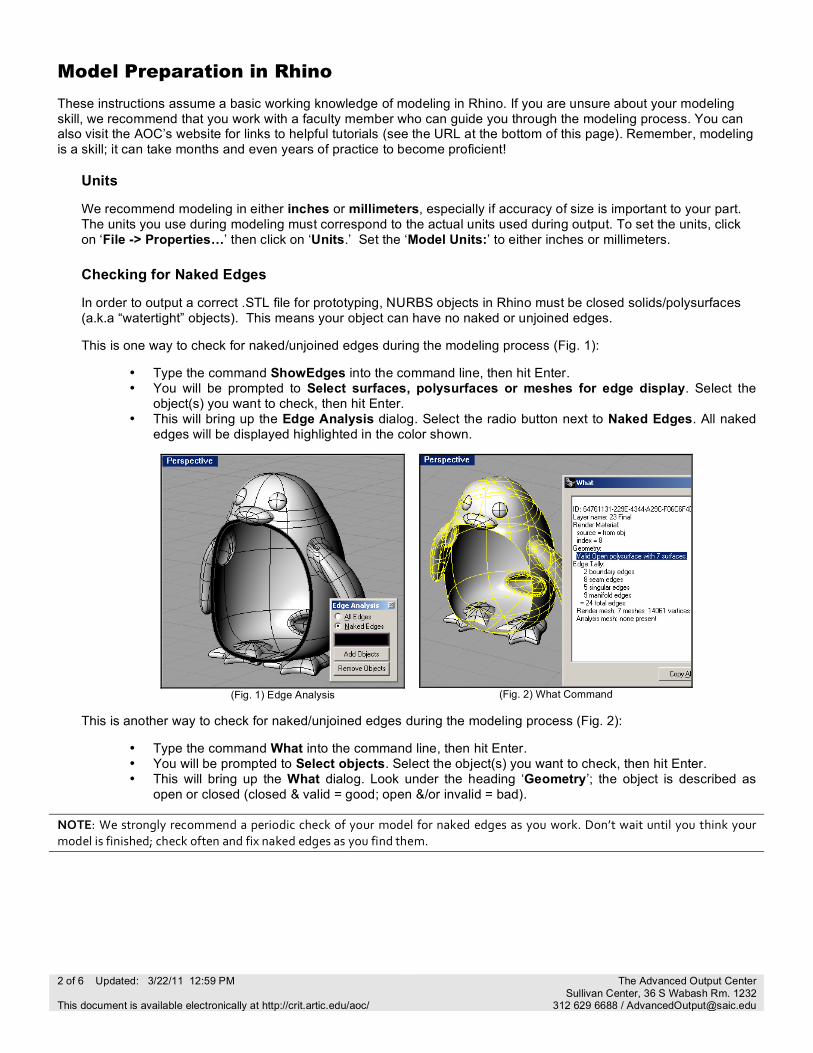
Checking for Naked Edges In order to output a correct .STL file for prototyping, NURBS objects in Rhino must be closed solids/polysurfaces (a.k.a “watertight” objects). This means your object can have no naked or unjoined edges. This is one way to check for naked/unjoined edges during the modeling process (Fig. 1):
• Type the command ShowEdges into the command line, then hit Enter. • You will be prompted to Select surfaces, polysurfaces or meshes for edge display. Select the
object(s) you want to check, then hit Enter. • This will bring up the Edge Analysis dialog. Select the radio button next to Naked Edges. All naked
edges will be displayed highlighted in the color shown.
(Fig. 1) Edge Analysis
(Fig. 2) What Command
This is another way to check for naked/unjoined edges during the modeling process (Fig. 2):
• Type the command What into the command line, then hit Enter. • You will be prompted to Select objects. Select the object(s) you want to check, then hit Enter. • This will bring up the What dialog. Look under the heading ‘Geometry’; the object is described as
open or closed (closed & valid = good; open &/or invalid = bad). NOTE: We strongly recommend a periodic check of your model for naked edges as you work. Don’t wait until you think your model is finished; check often and fix naked edges as you find them.
3 of 6 Updated: 3/22/11 12:59 PM This document is available electronically at http://crit.artic.edu/aoc/
The Advanced Output Center Sullivan Center, 36 S Wabash Rm. 1232
312 629 6688 / [email protected]
Repairing Naked Edges To join two naked edges once they have been located:
• Type the command JoinEdge into the command line, then hit Enter. • You will be prompted to Select two unjoined edges. Select the
edges you want to join, then hit Enter.
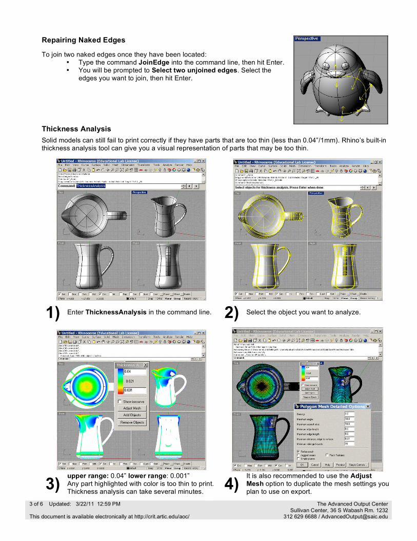
Thickness Analysis
Solid models can still fail to print correctly if they have parts that are too thin (less than 0.04”/1mm). Rhino’s built-in thickness analysis tool can give you a visual representation of parts that may be too thin.
1) Enter ThicknessAnalysis in the command line. 2) Select the object you want to analyze.
3) upper range: 0.04” lower range: 0.001” Any part highlighted with color is too thin to print. Thickness analysis can take several minutes. 4) It is also recommended to use the Adjust
Mesh option to duplicate the mesh settings you plan to use on export.
4 of 6 Updated: 3/22/11 12:59 PM This document is available electronically at http://crit.artic.edu/aoc/
The Advanced Output Center Sullivan Center, 36 S Wabash Rm. 1232
312 629 6688 / [email protected]
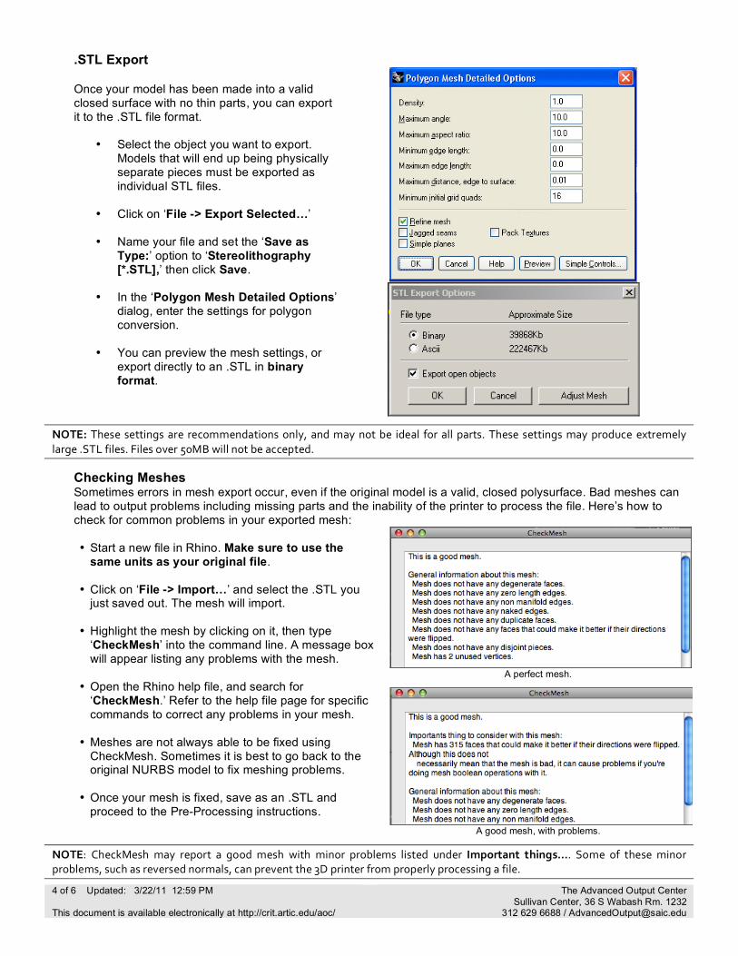
.STL Export
Once your model has been made into a valid closed surface with no thin parts, you can export it to the .STL file format.
• Select the object you want to export.
Models that will end up being physically separate pieces must be exported as individual STL files.
• Click on ‘File -> Export Selected…’
• Name your file and set the ‘Save as
Type:’ option to ‘Stereolithography [*.STL],’ then click Save.
• In the ‘Polygon Mesh Detailed Options’
dialog, enter the settings for polygon conversion.
• You can preview the mesh settings, or
export directly to an .STL in binary format.
NOTE: These settings are recommendations only, and may not be ideal for all parts. These settings may produce extremely large .STL files. Files over 50MB will not be accepted.
Checking Meshes Sometimes errors in mesh export occur, even if the original model is a valid, closed polysurface. Bad meshes can lead to output problems including missing parts and the inability of the printer to process the file. Here’s how to check for common problems in your exported mesh:
A perfect mesh.
• Start a new file in Rhino. Make sure to use the
same units as your original file. • Click on ‘File -> Import…’ and select the .STL you
just saved out. The mesh will import. • Highlight the mesh by clicking on it, then type
‘CheckMesh’ into the command line. A message box will appear listing any problems with the mesh.
• Open the Rhino help file, and search for
‘CheckMesh.’ Refer to the help file page for specific commands to correct any problems in your mesh.
• Meshes are not always able to be fixed using
CheckMesh. Sometimes it is best to go back to the original NURBS model to fix meshing problems.
• Once your mesh is fixed, save as an .STL and
proceed to the Pre-Processing instructions.
A good mesh, with problems.
NOTE: CheckMesh may report a good mesh with minor problems listed under Important things…. Some of these minor problems, such as reversed normals, can prevent the 3D printer from properly processing a file.
5 of 6 Updated: 3/22/11 12:59 PM This document is available electronically at http://crit.artic.edu/aoc/
The Advanced Output Center Sullivan Center, 36 S Wabash Rm. 1232
312 629 6688 / [email protected]
Pre-Processing Your File
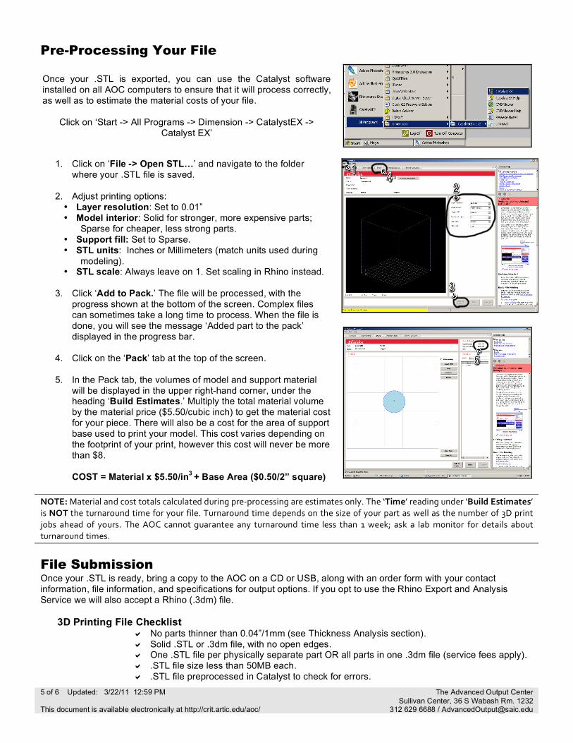
Once your .STL is exported, you can use the Catalyst software installed on all AOC computers to ensure that it will process correctly, as well as to estimate the material costs of your file.
Click on ‘Start -> All Programs -> Dimension -> CatalystEX ->
Catalyst EX’
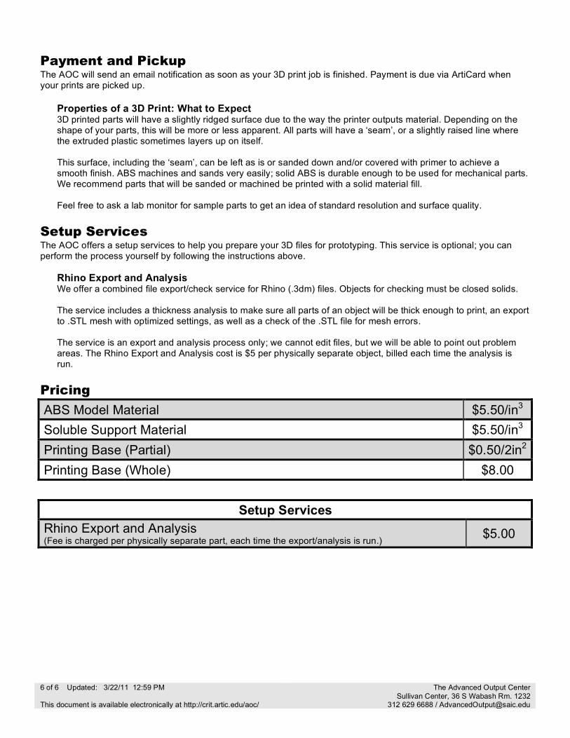
1. Click on ‘File -> Open STL…’ and navigate to the folder where your .STL file is saved.
2. Adjust printing options: • Layer resolution: Set to 0.01” • Model interior: Solid for stronger, more expensive parts;
Sparse for cheaper, less strong parts. • Support fill: Set to Sparse. • STL units: Inches or Millimeters (match units used during
modeling). • STL scale: Always leave on 1. Set scaling in Rhino instead.
3. Click ‘Add to Pack.’ The file will be processed, with the
progress shown at the bottom of the screen. Complex files can sometimes take a long time to process. When the file is done, you will see the message ‘Added part to the pack’ displayed in the progress bar.
4. Click on the ‘Pack’ tab at the top of the screen.
5. In the Pack tab, the volumes of model and support material
will be displayed in the upper right-hand corner, under the heading ‘Build Estimates.’ Multiply the total material volume by the material price ($5.50/cubic inch) to get the material cost for your piece. There will also be a cost for the area of support base used to print your model. This cost varies depending on the footprint of your print, however this cost will never be more than $8.
COST = Material x $5.50/in3 + Base Area ($0.50/2” square)
NOTE: Material and cost totals calculated during pre-‐processing are estimates only. The ‘Time’ reading under ‘Build Estimates’ is NOT the turnaround time for your file. Turnaround time depends on the size of your part as well as the number of 3D print jobs ahead of yours. The AOC cannot guarantee any turnaround time less than 1 week; ask a lab monitor for details about turnaround times.
File Submission Once your .STL is ready, bring a copy to the AOC on a CD or USB, along with an order form with your contact information, file information, and specifications for output options. If you opt to use the Rhino Export and Analysis Service we will also accept a Rhino (.3dm) file.
3D Printing File Checklist No parts thinner than 0.04”/1mm (see Thickness Analysis section). Solid .STL or .3dm file, with no open edges. One .STL file per physically separate part OR all parts in one .3dm file (service fees apply). .STL file size less than 50MB each. .STL file preprocessed in Catalyst to check for errors.
6 of 6 Updated: 3/22/11 12:59 PM This document is available electronically at http://crit.artic.edu/aoc/
The Advanced Output Center Sullivan Center, 36 S Wabash Rm. 1232
312 629 6688 / [email protected]
Payment and Pickup The AOC will send an email notification as soon as your 3D print job is finished. Payment is due via ArtiCard when your prints are picked up.
Properties of a 3D Print: What to Expect 3D printed parts will have a slightly ridged surface due to the way the printer outputs material. Depending on the shape of your parts, this will be more or less apparent. All parts will have a ‘seam’, or a slightly raised line where the extruded plastic sometimes layers up on itself. This surface, including the ‘seam’, can be left as is or sanded down and/or covered with primer to achieve a smooth finish. ABS machines and sands very easily; solid ABS is durable enough to be used for mechanical parts. We recommend parts that will be sanded or machined be printed with a solid material fill. Feel free to ask a lab monitor for sample parts to get an idea of standard resolution and surface quality.
Setup Services The AOC offers a setup services to help you prepare your 3D files for prototyping. This service is optional; you can perform the process yourself by following the instructions above.
Rhino Export and Analysis We offer a combined file export/check service for Rhino (.3dm) files. Objects for checking must be closed solids. The service includes a thickness analysis to make sure all parts of an object will be thick enough to print, an export to .STL mesh with optimized settings, as well as a check of the .STL file for mesh errors. The service is an export and analysis process only; we cannot edit files, but we will be able to point out problem areas. The Rhino Export and Analysis cost is $5 per physically separate object, billed each time the analysis is run.
Pricing
ABS Model Material $5.50/in3 Soluble Support Material $5.50/in3 Printing Base (Partial) $0.50/2in2 Printing Base (Whole) $8.00
Setup Services Rhino Export and Analysis (Fee is charged per physically separate part, each time the export/analysis is run.) $5.00


![A Dimensions: [mm] B Recommended land pattern: [mm] · 2020. 8. 11. · 2014-03-11 2013-12-19 2013-12-04 2013-04-10 2013-03-06 2013-02-14 2012-12-10 DATE SSt SSt SSt SSt SSt SSt SSt](https://img.pdfslide.net/doc/110x75/6145e75a8f9ff812541fec6f/a-dimensions-mm-b-recommended-land-pattern-mm-2020-8-11-2014-03-11-2013-12-19.jpg)


![A Dimensions: [mm] B Recommended land pattern: [mm] D ... · 2013-03-12 2013-01-13 2012-12-10 2012-10-29 2012-08-27 2006-05-05 DATE SSt SSt SSt SSt SSt SSt SSt BY SSt COt COt SSt](https://img.pdfslide.net/doc/110x75/604b228bc93c005c75431c51/a-dimensions-mm-b-recommended-land-pattern-mm-d-2013-03-12-2013-01-13.jpg)