Embed Size (px)
Citation preview
Diploma in Beverage Packaging (Beer)
Unit 2.3 Large Pack Operations - Keg
Pre-filling Operations
Learning Material © Institute of Brewing and Distilling 2012
Qualifications
2 Diploma in Beverage Packaging (Beer)
DIPOLMA IN PACKAGING (BEER) - MODULE 2
UNIT 2.3: Large Pack Operations - Keg
ELEMENT 2.3.2: Pre-filling Operations
ABSTRACT: This section gives a qualitative knowledge of
design and operation of unitising and de-unitising
equipment, as well as keg handling pre-washer. This section
also gives a qualitative knowledge of the design and
operation on container preparation equipment.
LEARNING OUTCOMES: : On completion of this unit you will
have:
1. An understanding of de-unitising, selective keg
turning plus unitising operations, including pallets
and locator boards.
2. Understand the key operating principles of
external keg washing including label removal.
SYLLABUS.
2.3.2.1 Container collation methods:
• Pallets (flat beds, belly)
• Locator boards
• Loose
2.3.2.2 De-unitizing:
• Traditional methods
• Robotic arms
• Pallet and locator board inspection
2.3.2.3 External keg washing and label removal:
• Overview and objectives of external keg
washing
• Current design capabilities
• Typical washer configurations and operations
• Maintenance and cleaning of equipment,
common faults and remedies
2.3.2.4 Keg orientation and spear torque tightness:
• Selective turning
• Spear torque tightness
Dipl.Pack Revision Notes v2 October 2012 3
Element 2.3.2
Pre-filling Operations
2.3.2.1 – CONTAINER COLLATION METHODS
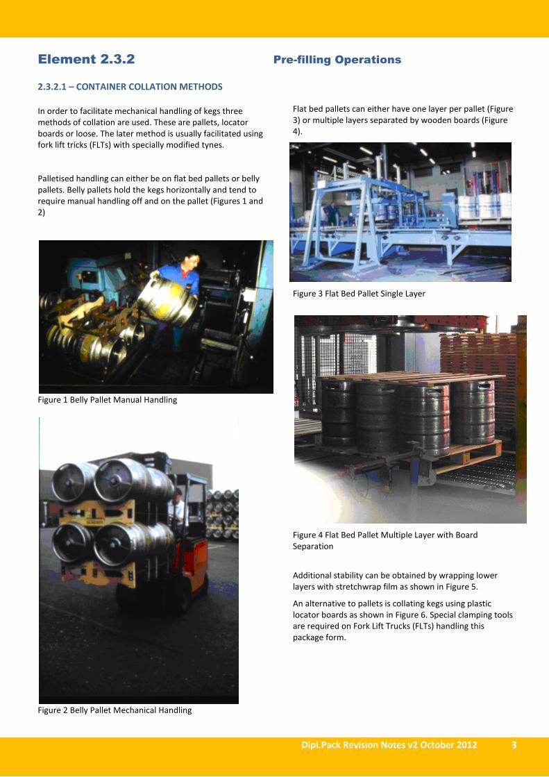
In order to facilitate mechanical handling of kegs three
methods of collation are used. These are pallets, locator
boards or loose. The later method is usually facilitated using
fork lift tricks (FLTs) with specially modified tynes.
Palletised handling can either be on flat bed pallets or belly
pallets. Belly pallets hold the kegs horizontally and tend to
require manual handling off and on the pallet (Figures 1 and
2)
Figure 1 Belly Pallet Manual Handling
Figure 2 Belly Pallet Mechanical Handling
Flat bed pallets can either have one layer per pallet (Figure
3) or multiple layers separated by wooden boards (Figure
4).
Figure 3 Flat Bed Pallet Single Layer
Figure 4 Flat Bed Pallet Multiple Layer with Board
Separation
Additional stability can be obtained by wrapping lower
layers with stretchwrap film as shown in Figure 5.
An alternative to pallets is collating kegs using plastic
locator boards as shown in Figure 6. Special clamping tools
are required on Fork Lift Trucks (FLTs) handling this
package form.
4 Diploma in Beverage Packaging (Beer)
Figure 5 Flat Bed Pallet multiple Layer with Stretchwrap
Figure 6 Kegs stacked using Locator Boards to assist
collation
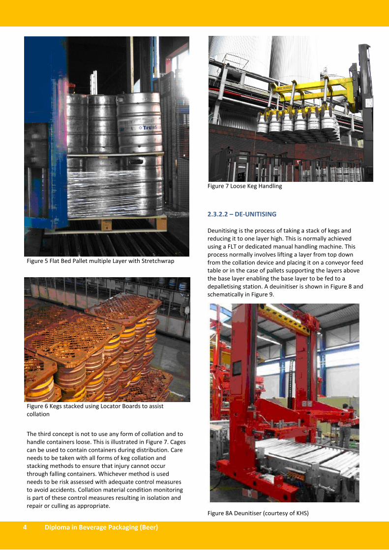
The third concept is not to use any form of collation and to
handle containers loose. This is illustrated in Figure 7. Cages
can be used to contain containers during distribution. Care
needs to be taken with all forms of keg collation and
stacking methods to ensure that injury cannot occur
through falling containers. Whichever method is used
needs to be risk assessed with adequate control measures
to avoid accidents. Collation material condition monitoring
is part of these control measures resulting in isolation and
repair or culling as appropriate.
Figure 7 Loose Keg Handling
2.3.2.2 – DE-UNITISING
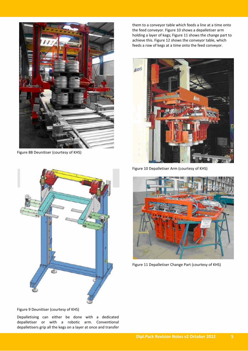
Deunitising is the process of taking a stack of kegs and
reducing it to one layer high. This is normally achieved
using a FLT or dedicated manual handling machine. This
process normally involves lifting a layer from top down
from the collation device and placing it on a conveyor feed
table or in the case of pallets supporting the layers above
the base layer enabling the base layer to be fed to a
depalletising station. A deuinitiser is shown in Figure 8 and
schematically in Figure 9.
Figure 8A Deunitiser (courtesy of KHS)
Dipl.Pack Revision Notes v2 October 2012 5
Figure 8B Deunitiser (courtesy of KHS)
Figure 9 Deunitiser (courtesy of KHS)
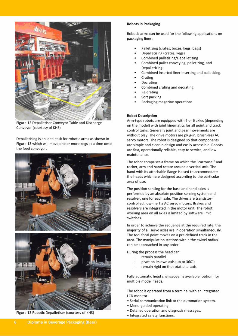
Depalletising can either be done with a dedicated
depalletiser or with a robotic arm. Conventional
depalletisers grip all the kegs on a layer at once and transfer
them to a conveyor table which feeds a line at a time onto
the feed conveyor. Figure 10 shows a depalletiser arm
holding a layer of kegs; Figure 11 shows the change part to
achieve this. Figure 12 shows the conveyor table, which
feeds a row of kegs at a time onto the feed conveyor.
Figure 10 Depalletiser Arm (courtesy of KHS)
Figure 11 Depalletiser Change Part (courtesy of KHS)
6 Diploma in Beverage Packaging (Beer)
Figure 12 Depalletiser Conveyor Table and Discharge
Conveyor (courtesy of KHS)
Depalletising is an ideal task for robotic arms as shown in
Figure 13 which will move one or more kegs at a time onto
the feed conveyor.
Figure 13 Robotic Depalletiser (courtesy of KHS)
Robots in Packaging
Robotic arms can be used for the following applications on
packaging lines:
• Palletizing (crates, boxes, kegs, bags)
• Depalletizing (crates, kegs)
• Combined palletizing/Depalletizing
• Combined pallet conveying, palletizing, and
Depalletizing.
• Combined inserted liner inserting and palletizing.
• Crating
• Decrating
• Combined crating and decrating
• Re-crating
• Sort packing
• Packaging magazine operations
Robot Description
Arm-type robots are equipped with 5 or 6 axles (depending
on the model) with joint kinematics for all point and track
control tasks. Generally joint and gear movements are
without play. The drive motors are plug-in, brush-less AC
servo motors. The robot is designed so that components
are simple and clear in design and easily accessible. Robots
are fast, operationally reliable, easy to service, and low
maintenance.
The robot comprises a frame on which the "carrousel" and
rocker, arm and hand rotate around a vertical axis. The
hand with its attachable flange is used to accommodate
the heads which are designed according to the particular
area of use.
The position sensing for the base and hand axles is
performed by an absolute position sensing system and
resolver, one for each axle. The drives are transistor-
controlled, low-inertia AC servo motors. Brakes and
resolvers are integrated in the motor unit. The robot
working area on all axles is limited by software limit
switches.
In order to achieve the sequence at the required rate, the
majority of all servo axles are in operation simultaneously.
The tool focal point moves on a pre-defined track in the
area. The manipulation stations within the swivel radius
can be approached in any order.
During the process the head can
- remain parallel
- pivot on its own axis (up to 360°)
- remain rigid on the rotational axis.
Fully automatic head changeover is available (option) for
multiple model heads.
The robot is operated from a terminal with an integrated
LCD monitor.
• Serial communication link to the automation system.
• Menu-guided operating
• Detailed operation and diagnosis messages.
• Integrated safety functions.
Dipl.Pack Revision Notes v2 October 2012 7
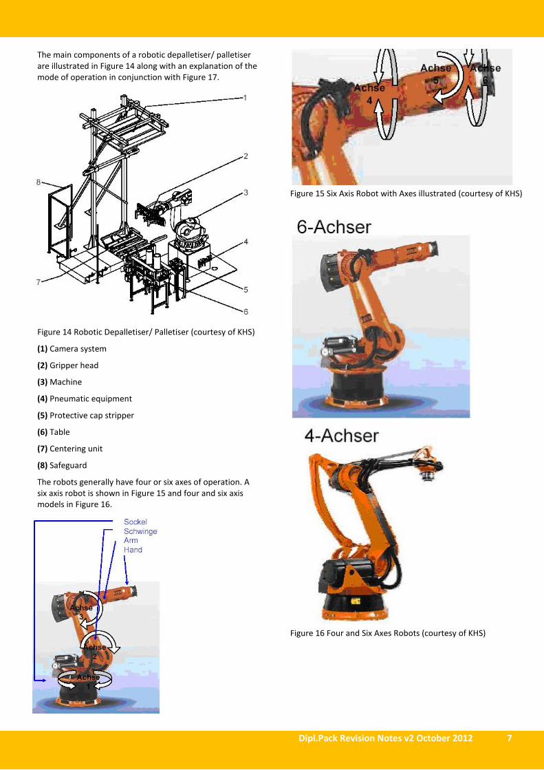
The main components of a robotic depalletiser/ palletiser
are illustrated in Figure 14 along with an explanation of the
mode of operation in conjunction with Figure 17.
Figure 14 Robotic Depalletiser/ Palletiser (courtesy of KHS)
(1) Camera system
(2) Gripper head
(3) Machine
(4) Pneumatic equipment
(5) Protective cap stripper
(6) Table
(7) Centering unit
(8) Safeguard
The robots generally have four or six axes of operation. A
six axis robot is shown in Figure 15 and four and six axis
models in Figure 16.
Figure 15 Six Axis Robot with Axes illustrated (courtesy of KHS)
Figure 16 Four and Six Axes Robots (courtesy of KHS)
8 Diploma in Beverage Packaging (Beer)
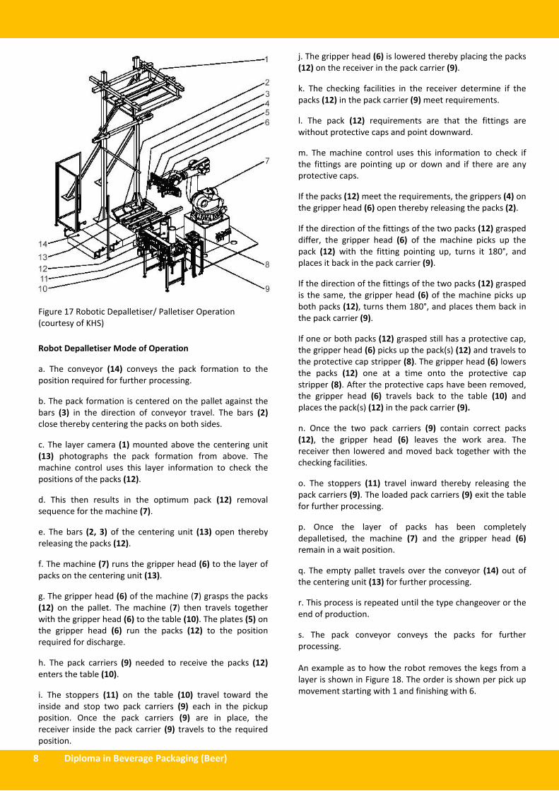
Figure 17 Robotic Depalletiser/ Palletiser Operation
(courtesy of KHS)
Robot Depalletiser Mode of Operation
a. The conveyor (14) conveys the pack formation to the
position required for further processing.
b. The pack formation is centered on the pallet against the
bars (3) in the direction of conveyor travel. The bars (2)
close thereby centering the packs on both sides.
c. The layer camera (1) mounted above the centering unit
(13) photographs the pack formation from above. The
machine control uses this layer information to check the
positions of the packs (12).
d. This then results in the optimum pack (12) removal
sequence for the machine (7).
e. The bars (2, 3) of the centering unit (13) open thereby
releasing the packs (12).
f. The machine (7) runs the gripper head (6) to the layer of
packs on the centering unit (13).
g. The gripper head (6) of the machine (7) grasps the packs
(12) on the pallet. The machine (7) then travels together
with the gripper head (6) to the table (10). The plates (5) on
the gripper head (6) run the packs (12) to the position
required for discharge.
h. The pack carriers (9) needed to receive the packs (12)
enters the table (10).
i. The stoppers (11) on the table (10) travel toward the
inside and stop two pack carriers (9) each in the pickup
position. Once the pack carriers (9) are in place, the
receiver inside the pack carrier (9) travels to the required
position.
j. The gripper head (6) is lowered thereby placing the packs
(12) on the receiver in the pack carrier (9).
k. The checking facilities in the receiver determine if the
packs (12) in the pack carrier (9) meet requirements.
l. The pack (12) requirements are that the fittings are
without protective caps and point downward.
m. The machine control uses this information to check if
the fittings are pointing up or down and if there are any
protective caps.
If the packs (12) meet the requirements, the grippers (4) on
the gripper head (6) open thereby releasing the packs (2).
If the direction of the fittings of the two packs (12) grasped
differ, the gripper head (6) of the machine picks up the
pack (12) with the fitting pointing up, turns it 180°, and
places it back in the pack carrier (9).
If the direction of the fittings of the two packs (12) grasped
is the same, the gripper head (6) of the machine picks up
both packs (12), turns them 180°, and places them back in
the pack carrier (9).
If one or both packs (12) grasped still has a protective cap,
the gripper head (6) picks up the pack(s) (12) and travels to
the protective cap stripper (8). The gripper head (6) lowers
the packs (12) one at a time onto the protective cap
stripper (8). After the protective caps have been removed,
the gripper head (6) travels back to the table (10) and
places the pack(s) (12) in the pack carrier (9).
n. Once the two pack carriers (9) contain correct packs
(12), the gripper head (6) leaves the work area. The
receiver then lowered and moved back together with the
checking facilities.
o. The stoppers (11) travel inward thereby releasing the
pack carriers (9). The loaded pack carriers (9) exit the table
for further processing.
p. Once the layer of packs has been completely
depalletised, the machine (7) and the gripper head (6)
remain in a wait position.
q. The empty pallet travels over the conveyor (14) out of
the centering unit (13) for further processing.
r. This process is repeated until the type changeover or the
end of production.
s. The pack conveyor conveys the packs for further
processing.
An example as to how the robot removes the kegs from a
layer is shown in Figure 18. The order is shown per pick up
movement starting with 1 and finishing with 6.

Dipl.Pack Revision Notes v2 October 2012 9
Figure 18 Robotic Depalletiser Keg Removal Sequence
(courtesy of KHS)
Palletising is the reverse of depalletising where the control
emphasis is on locating the kegs on the collation medium to
be used plus correct placement of the collation medium
used to separate layers. Robotic arms are commonly used
for these operations as described above and shown in
Figure 19. The alternative is dedicated machines to collate
kegs on the collation medium as shown in Figures 20 and
21.
Figure 19A Robotic Palletiser (courtesy of KHS)
Figure 19B Robotic Palletiser (courtesy of KHS)
Figure 20 Palletiser Collation Conveyor Table (courtesy of
KHS)

10 Diploma in Beverage Packaging (Beer)
Figure 21 Palletiser (courtesy of KHS)
The layout of a line rated at 160 kegs per hour using one
robot is shown in Figure 22.
Figure 22 Line layout 160 keg/hr (courtesy of KHS)
Robot Depalletiser Maintenance Examples
Electrical Maintenance
Switchgears with mechanical contacts are subject to wear.
For service life and the highest possible rate of switching
cycles, cf. manufacturer’s lists.
Electronic appliances are wear-resistant and maintenance-
free. Care should be taken to ensure that there is sufficient
cooling and dry circulation air. The filter mats of the filter
ventilators must be cleaned or replaced regularly (according
to local conditions).
For three-phase motors it is sufficient to keep the cooling
air duct clean and to check the antifriction bearings
regularly.
Light Barriers, Light Scanners
Daily cleaning of lenses and reflectors prior to operation
start-up. Be sure that light barriers, light scanners,
electronic and optical appliances are not splashed during
cleaning.
Dipl.Pack Revision Notes v2 October 2012 11
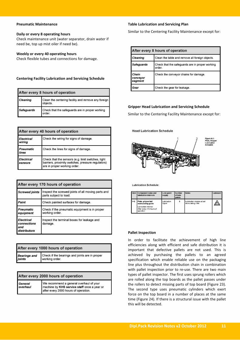
Pneumatic Maintenance
Daily or every 8 operating hours
Check maintenance unit (water separator, drain water if
need be, top up mist oiler if need be).
Weekly or every 40 operating hours
Check flexible tubes and connections for damage.
Centering Facility Lubrication and Servicing Schedule
Table Lubrication and Servicing Plan
Similar to the Centering Facility Maintenance except for:
Gripper Head Lubrication and Servicing Schedule
Similar to the Centering Facility Maintenance except for:
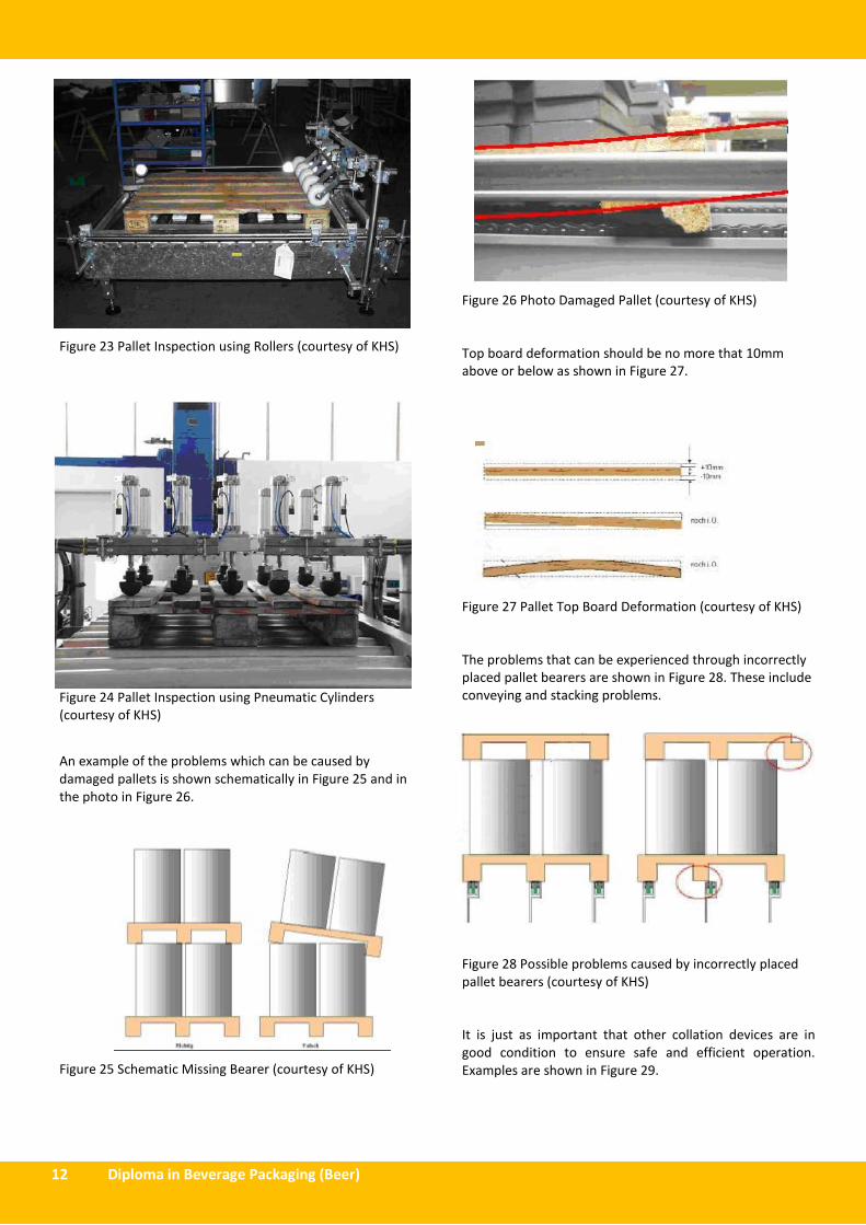
Pallet Inspection
In order to facilitate the achievement of high line
efficiencies along with efficient and safe distribution it is
important that defective pallets are not used. This is
achieved by purchasing the pallets to an agreed
specification which enable reliable use on the packaging
line plus throughout the distribution chain in combination
with pallet inspection prior to re-use. There are two main
types of pallet inspector. The first uses sprung rollers which
are rolled along the top boards as the pallet passes under
the rollers to detect missing parts of top board (Figure 23).
The second type uses pneumatic cylinders which exert
force on the top board in a number of places at the same
time (Figure 24). If there is a structural issue with the pallet
this will be detected.
12 Diploma in Beverage Packaging (Beer)
Figure 23 Pallet Inspection using Rollers (courtesy of KHS)
Figure 24 Pallet Inspection using Pneumatic Cylinders
(courtesy of KHS)
An example of the problems which can be caused by
damaged pallets is shown schematically in Figure 25 and in
the photo in Figure 26.
Figure 25 Schematic Missing Bearer (courtesy of KHS)
Figure 26 Photo Damaged Pallet (courtesy of KHS)
Top board deformation should be no more that 10mm
above or below as shown in Figure 27.
Figure 27 Pallet Top Board Deformation (courtesy of KHS)
The problems that can be experienced through incorrectly
placed pallet bearers are shown in Figure 28. These include
conveying and stacking problems.
Figure 28 Possible problems caused by incorrectly placed
pallet bearers (courtesy of KHS)
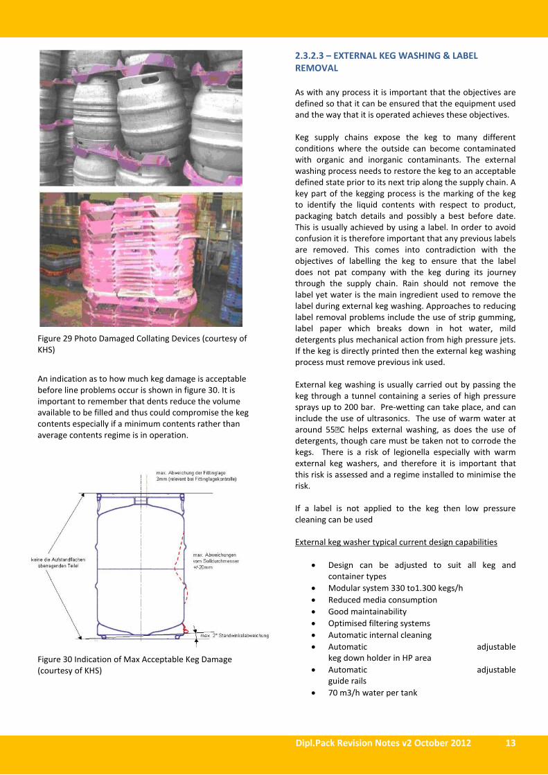
It is just as important that other collation devices are in
good condition to ensure safe and efficient operation.
Examples are shown in Figure 29.
Dipl.Pack Revision Notes v2 October 2012 13
Figure 29 Photo Damaged Collating Devices (courtesy of
KHS)
An indication as to how much keg damage is acceptable
before line problems occur is shown in figure 30. It is
important to remember that dents reduce the volume
available to be filled and thus could compromise the keg
contents especially if a minimum contents rather than
average contents regime is in operation.
Figure 30 Indication of Max Acceptable Keg Damage
(courtesy of KHS)
2.3.2.3 – EXTERNAL KEG WASHING & LABEL
REMOVAL
As with any process it is important that the objectives are
defined so that it can be ensured that the equipment used
and the way that it is operated achieves these objectives.
Keg supply chains expose the keg to many different
conditions where the outside can become contaminated
with organic and inorganic contaminants. The external
washing process needs to restore the keg to an acceptable
defined state prior to its next trip along the supply chain. A
key part of the kegging process is the marking of the keg
to identify the liquid contents with respect to product,
packaging batch details and possibly a best before date.
This is usually achieved by using a label. In order to avoid
confusion it is therefore important that any previous labels
are removed. This comes into contradiction with the
objectives of labelling the keg to ensure that the label
does not pat company with the keg during its journey
through the supply chain. Rain should not remove the
label yet water is the main ingredient used to remove the
label during external keg washing. Approaches to reducing
label removal problems include the use of strip gumming,
label paper which breaks down in hot water, mild
detergents plus mechanical action from high pressure jets.
If the keg is directly printed then the external keg washing
process must remove previous ink used.
External keg washing is usually carried out by passing the
keg through a tunnel containing a series of high pressure
sprays up to 200 bar. Pre-wetting can take place, and can
include the use of ultrasonics. The use of warm water at
around 55C helps external washing, as does the use of
detergents, though care must be taken not to corrode the
kegs. There is a risk of legionella especially with warm
external keg washers, and therefore it is important that
this risk is assessed and a regime installed to minimise the
risk.
If a label is not applied to the keg then low pressure
cleaning can be used
External keg washer typical current design capabilities
• Design can be adjusted to suit all keg and
container types
• Modular system 330 to1.300 kegs/h
• Reduced media consumption
• Good maintainability
• Optimised filtering systems
• Automatic internal cleaning
• Automatic adjustable
keg down holder in HP area
• Automatic adjustable
guide rails
• 70 m3/h water per tank
14 Diploma in Beverage Packaging (Beer)
External keg washer typical configuration
The design depends on the cleaning rate required and the
cleaning duty. The cleaning duty will depend on whether
labels need to be removed from the top of the keg along
with the materials of construction of the keg. Stainless steel
is the material used for most kegs today. There are many
aluminium kegs in service and these will be less resistant to
the use of caustic for external cleaning. Supply chain
conditions will also affect the cleaning duty. Kegs which
have baked on soil from long distribution chains in hot
conditions will require more external cleaning effort.
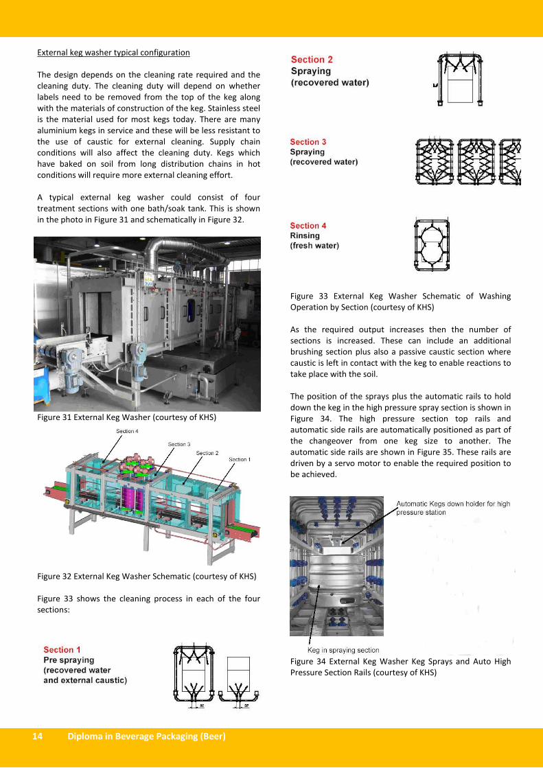
A typical external keg washer could consist of four
treatment sections with one bath/soak tank. This is shown
in the photo in Figure 31 and schematically in Figure 32.
Figure 31 External Keg Washer (courtesy of KHS)
Figure 32 External Keg Washer Schematic (courtesy of KHS)
Figure 33 shows the cleaning process in each of the four
sections:
Figure 33 External Keg Washer Schematic of Washing
Operation by Section (courtesy of KHS)
As the required output increases then the number of
sections is increased. These can include an additional
brushing section plus also a passive caustic section where
caustic is left in contact with the keg to enable reactions to
take place with the soil.
The position of the sprays plus the automatic rails to hold
down the keg in the high pressure spray section is shown in
Figure 34. The high pressure section top rails and
automatic side rails are automatically positioned as part of
the changeover from one keg size to another. The
automatic side rails are shown in Figure 35. These rails are
driven by a servo motor to enable the required position to
be achieved.
Figure 34 External Keg Washer Keg Sprays and Auto High
Pressure Section Rails (courtesy of KHS)
Dipl.Pack Revision Notes v2 October 2012 15
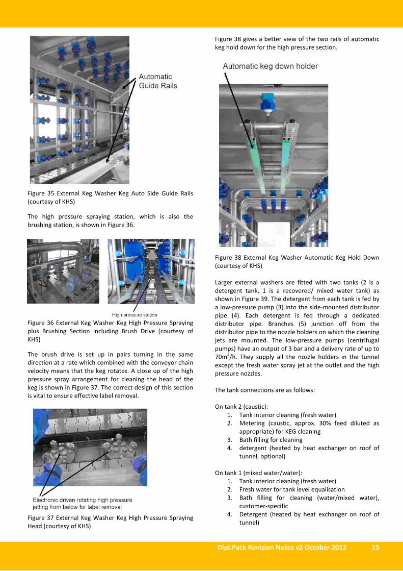
Figure 35 External Keg Washer Keg Auto Side Guide Rails
(courtesy of KHS)
The high pressure spraying station, which is also the
brushing station, is shown in Figure 36.
Figure 36 External Keg Washer Keg High Pressure Spraying
plus Brushing Section including Brush Drive (courtesy of
KHS)
The brush drive is set up in pairs turning in the same
direction at a rate which combined with the conveyor chain
velocity means that the keg rotates. A close up of the high
pressure spray arrangement for cleaning the head of the
keg is shown in Figure 37. The correct design of this section
is vital to ensure effective label removal.
Figure 37 External Keg Washer Keg High Pressure Spraying
Head (courtesy of KHS)
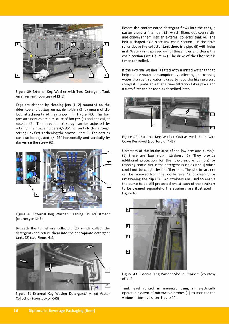
Figure 38 gives a better view of the two rails of automatic
keg hold down for the high pressure section.
Figure 38 External Keg Washer Automatic Keg Hold Down
(courtesy of KHS)
Larger external washers are fitted with two tanks (2 is a
detergent tank, 1 is a recovered/ mixed water tank) as
shown in Figure 39. The detergent from each tank is fed by
a low-pressure pump (3) into the side-mounted distributor
pipe (4). Each detergent is fed through a dedicated
distributor pipe. Branches (5) junction off from the
distributor pipe to the nozzle holders on which the cleaning
jets are mounted. The low-pressure pumps (centrifugal
pumps) have an output of 3 bar and a delivery rate of up to
70m3/h. They supply all the nozzle holders in the tunnel
except the fresh water spray jet at the outlet and the high
pressure nozzles.
The tank connections are as follows:
On tank 2 (caustic):
1. Tank interior cleaning (fresh water)
2. Metering (caustic, approx. 30% feed diluted as
appropriate) for KEG cleaning
3. Bath filling for cleaning
4. detergent (heated by heat exchanger on roof of
tunnel, optional)
On tank 1 (mixed water/water):
1. Tank interior cleaning (fresh water)
2. Fresh water for tank level equalisation
3. Bath filling for cleaning (water/mixed water),
customer-specific
4. Detergent (heated by heat exchanger on roof of
tunnel)
16 Diploma in Beverage Packaging (Beer)
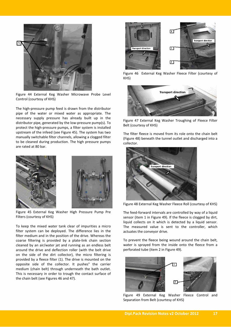
Figure 39 External Keg Washer with Two Detergent Tank
Arrangement (courtesy of KHS)
Kegs are cleaned by cleaning jets (1, 2) mounted on the
sides, top and bottom on nozzle holders (3) by means of clip
lock attachments (4), as shown in Figure 40. The low
pressure nozzles are a mixture of fan jets (1) and conical jet
nozzles (2). The direction of spray can be adjusted by
rotating the nozzle holders +/- 35° horizontally (for a rough
setting), by first slackening the screws - item 5). The nozzles
can also be adjusted +/- 35° horizontally and vertically by
slackening the screw (6).
Figure 40 External Keg Washer Cleaning Jet Adjustment
(courtesy of KHS)
Beneath the tunnel are collectors (1) which collect the
detergents and return them into the appropriate detergent
tanks (2) (see Figure 41).
Figure 41 External Keg Washer Detergent/ Mixed Water
Collection (courtesy of KHS)
Before the contaminated detergent flows into the tank, it
passes along a filter belt (3) which filters out coarse dirt
and conveys them into an external collector tank (4). The
belt is shaped as a plate-link chain section. On the drive
roller above the collector tank there is a pipe (5) with holes
in it. Water/air is sprayed out of these holes and cleans the
chain section (see Figure 42). The drive of the filter belt is
timer-controlled.
If the external washer is fitted with a mixed water tank to
help reduce water consumption by collecting and re-using
water then as this water is used to feed the high pressure
sprays it is preferable that a finer filtration takes place and
a cloth filter can be used as described later.
Figure 42 External Keg Washer Coarse Mesh Filter with
Cover Removed (courtesy of KHS)
Upstream of the intake area of the low-pressure pump(s)
(1) there are four slot-in strainers (2). They provide
additional protection for the low-pressure pump(s) by
trapping coarse dirt in the detergent (such as labels) which
could not be caught by the filter belt. The slot-in strainer
can be removed from the profile rails (4) for cleaning by
unfastening the clip (3). Two strainers are used to enable
the pump to be still protected whilst each of the strainers
to be cleaned separately. The strainers are illustrated in
Figure 43.
Figure 43 External Keg Washer Slot In Strainers (courtesy
of KHS)
Tank level control in managed using an electrically
operated system of microwave probes (1) to monitor the
various filling levels (see Figure 44).
Dipl.Pack Revision Notes v2 October 2012 17
Figure 44 External Keg Washer Microwave Probe Level
Control (courtesy of KHS)
The high-pressure pump feed is drawn from the distributor
pipe of the water or mixed water as appropriate. The
necessary supply pressure has already built up in the
distributor pipe, generated by the low-pressure pump(s). To
protect the high-pressure pumps, a filter system is installed
upstream of the infeed (see Figure 45). The system has two
manually switchable filter channels, allowing a clogged filter
to be cleaned during production. The high pressure pumps
are rated at 80 bar.
Figure 45 External Keg Washer High Pressure Pump Pre
Filters (courtesy of KHS)
To keep the mixed water tank clear of impurities a micro
filter system can be deployed. The difference lies in the
filter medium and in the position of the drive. Whereas the
coarse filtering is provided by a plate-link chain section
cleaned by an air/water jet and running as an endless belt
around the drive and deflection roller (with the belt drive
on the side of the dirt collector), the micro filtering is
provided by a fleece filter (1). The drive is mounted on the
opposite side of the collector. It pushes" the carrier
medium (chain belt) through underneath the bath outlet.
This is necessary in order to trough the contact surface of
the chain belt (see Figures 46 and 47).
Figure 46 External Keg Washer Fleece Filter (courtesy of
KHS)
Figure 47 External Keg Washer Troughing of Fleece Filter
Belt (courtesy of KHS)
The filter fleece is moved from its role onto the chain belt
(Figure 48) beneath the tunnel outlet and discharged into a
collector.
Figure 48 External Keg Washer Fleece Roll (courtesy of KHS)
The feed-forward intervals are controlled by way of a liquid
sensor (item 1 in Figure 49). If the fleece is clogged by dirt,
liquid collects on it which is detected by a liquid sensor.
The measured value is sent to the controller, which
actuates the conveyor drive.
To prevent the fleece being wound around the chain belt,
water is sprayed from the inside onto the fleece from a
perforated tube (item 2 in Figure 49).
Figure 49 External Keg Washer Fleece Control and
Separation from Belt (courtesy of KHS)
18 Diploma in Beverage Packaging (Beer)
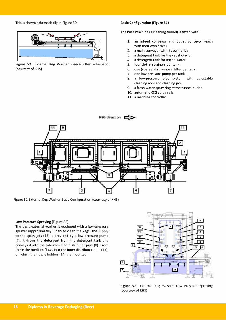
This is shown schematically in Figure 50.
Figure 50 External Keg Washer Fleece Filter Schematic
(courtesy of KHS)
Basic Configuration (Figure 51)
The base machine (a cleaning tunnel) is fitted with:
1. an infeed conveyor and outlet conveyor (each
with their own drive)
2. a main conveyor with its own drive
3. a detergent tank for the caustic/acid
4. a detergent tank for mixed water
5. four slot-in strainers per tank
6. one (coarse) dirt removal filter per tank
7. one low-pressure pump per tank
8. a low-pressure pipe system with adjustable
cleaning rods and cleaning jets
9. a fresh water spray ring at the tunnel outlet
10. automatic KEG guide rails
11. a machine controller
Figure 51 External Keg Washer Basic Configuration (courtesy of KHS)
Low Pressure Spraying (Figure 52)
The basic external washer is equipped with a low-pressure
sprayer (approximately 3 bar) to clean the kegs. The supply
to the spray jets (12) is provided by a low-pressure pump
(7). It draws the detergent from the detergent tank and
conveys it into the side-mounted distributor pipe (8). From
there the medium flows into the inner distributor pipe (13),
on which the nozzle holders (14) are mounted.
Figure 52 External Keg Washer Low Pressure Spraying
(courtesy of KHS)

Dipl.Pack Revision Notes v2 October 2012 19
Additional Possible Features (Figure 53)
1. Fine dirt removal filter
High-pressure sprayer comprising
2. 2 High-pressure pump
3. 3 High-pressure jets (rotating)
4. Micro filter for high-pressure pump
5. Brush station
6. Heat exchanger
7. KEG hold-down
8. Tank interior cleaner
9. Vent air system
Figure 53 External Keg Washer Additional Possible Features (courtesy of KHS)
High Pressure Spraying (Figure 54)
In addition to the low-pressure sprayer, the external
washer can also be equipped with a high-pressure spray
system to remove resistant dirt and adhesive residues from
the keg head, such as those which the cleaning brushes are
unable to reach. The cleaning is carried out by rotating jets
(see item 1 in Figure 2.24). The high-pressure medium is
drawn from the distributor pipe of the water or mixed
water segment as appropriate (item 2 in Figure 2.24). The
necessary supply pressure of min. 2 bar (generated by the
low-pressure pump) should be present in the distributor
feed pipe. If this supply pressure is not attained, the high-
pressure pump automatically shuts down. As a further
protective measure for the high-pressure pumps, an
additional safety filter system is installed on the high
pressure pump feed. The filter system consists of two filter
housings one of which is in use and the other is clean
awaiting changeover. If the open filter becomes clogged,
the permeability is reduced, and thus the supply pressure
for the high-pressure pump too. A pressure sensor installed
downstream of the filter system monitors the high-pressure
pump supply pressure. If the pressure falls below a value
entered on the PLC (> 2 bar), a warning message is
generated to provide the operator with time to open the
clean filter channel (shut-off valves) and then close off the
contaminated channel. Then the contaminated filter can be
removed and cleaned.
Figure 54 External Keg Washer High Pressure Spraying
(courtesy of KHS)

20 Diploma in Beverage Packaging (Beer)
External keg washer Maintenance
Below are a series of possible maintenance checks and their
frequency from daily through to every 24 months:
2.3.2.4 – KEG ORIENTATION AND SPEAR TORQUE
TIGHTNESS
Selective Keg Turning
Following depalletising the keg needs to be turned so that
the Barnes neck points downwards i.e. the keg is upside
down. This will enable the keg to be internally washed and
then filled in this inverted position. When the kegs are
collated prior to returning to the packaging plan they are
often not all collated the right way up or upside down.
Therefore not all kegs will need to be turned so as to
ensure that they are in the upside down position. In order
to achieve this a selective keg turner is used. This uses a
flap which detects the presence of the Barnes neck on a
right way up keg which is then turned. The Barnes neck is
not detected on an upside down keg and thus is not
turned. Turning is achieved by clamping the keg between
two curved clamps, lifting it off the conveyor and rotating it
by 180 degrees, after which it is placed back on the
conveyor. If kegs are depalletised one keg at a time by a
robotic depalletiser then a camera can be used to make the
decision whether to rotate the keg prior to placing it on the
feed conveyor to ensure all kegs are placed on the
conveyor in the upside down position. This would negate
the need of for a selective turner.
Keg Cap Removal
If keg caps are used which are not tamper evident and then
there is a risk that these will be placed on top of the keg
spears after use. If this is the case then these need to be
removed prior to washing and filling. A camera system can
be used to detect the presence of a cap and this is then
removed post selective turning from the upturned keg. This
is done by gripping the cap and pulling it off the keg head.
A system for achieving this shown in Figure 55.
Figure 55. Keg Cap Removal System (courtesy of KHS)