Embed Size (px)
Citation preview
Solenoid Free to RotateThrough 360º
316L Stainless Steel SolenoidEnclosure and Valve
NACE MR-01-75 Internal Wetted and Body Materials (Option)
Low Power
Arctic Service Options to -36ºC
Up to 690 bar Working Pressure
Worldwide Solenoid ApprovalsEx d, Ex ia, Ex emb and Explosion Proof
Compact Design
Seated Ball Design Offers Extremely Low Leakage (Less AccumulationRequired, Smaller Pump Size & Duty)
ATEX Registered
Solenoid Valve
Innovative and ReliableValve Solutions
www.bifold.co.uk
Global Presence forPeace of Mind
Superior Performance Throughout the Full Operational Range
Direct Acting Solenoid ValvesModel FP01 (Up to 690 bar, 1 litre per minute)
is a member of the
of companies
www.bifold.co.uk
BFD87 November‘13 © Bifold 2013
Solenoid Valve Range
2
Worldwide Approvals
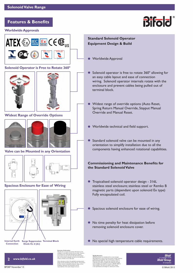
Spacious Enclosure for Ease of Wiring
Widest Range of Override Options
Solenoid Operator is Free to Rotate 360º
Valve can be Mounted in any Orientation
Standard Solenoid Operator Equipment Design & Build
Worldwide Approval
Solenoid operator is free to rotate 360º allowing for an easy cable layout and ease of connection wiring. Solenoid operator internals rotate with the enclosure and prevent cables being pulled out of terminal block.
Widest range of override options (Auto Reset, Spring Return Manual Override, Stayput Manual Override and Manual Reset.
Standard solenoid valve can be mounted in any orientation to simplify installation due to all the components having enhanced rotational capabilities.
the Standard Solenoid Valve
Tropicalised solenoid operator design - 316L stainless steel enclosure; stainless steel or Remko B magnetic parts (dependant upon solenoid Ex type) Fully encapsulated coil.
Spacious solenoid enclosure for ease of wiring.
No time penalty for heat dissipation before removing solenoid enclosure cover.
No special high temperature cable requirements.Terminal BlockSurge SuppressionDiode Ex d (dc)
Internal Earth Connection
ATEXRegistered
Accuracy of informationWe take care to ensure that product information in thiscatalogue is reasonably accurate and up-to-date. However,our products are continually developed and updatedso to ensure accurate and up-to-date information pleaserefer to the product catalogue issue list on our web site orcontact a member of our sales team.
When selecting a product, the applicable operating systemdesign must be considered to ensure safe use. The productsfunction, material compatibility, adequate ratings, correctinstallation, operation and maintenance are theresponsibilities of the system designer and user.
Quality AssuranceAll Bifold products are manufactured to a most stringentQA programme to ensure that every product will give optimum
total traceability are available on request, to BS EN 10204 3.1where available. We reserve the right to make changes
is a member of the
of companies
www.bifold.co.uk
BFD87 November‘13 © Bifold 2013
33
Solenoid Valve Range
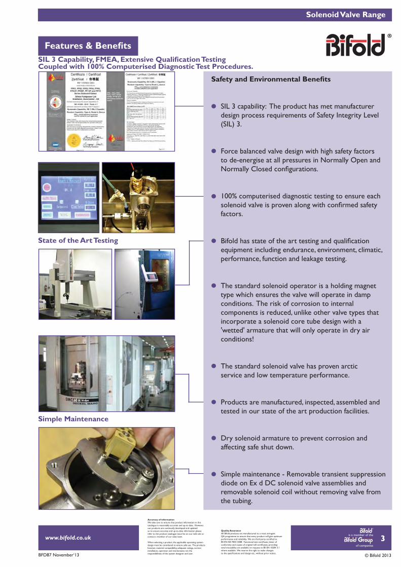
Simple Maintenance
State of the Art Testing
Coupled with 100% Computerised Diagnostic Test Procedures.
SIL 3 capability: The product has met manufacturer design process requirements of Safety Integrity Level (SIL) 3.
Force balanced valve design with high safety factors to de-energise at all pressures in Normally Open and
100% computerised diagnostic testing to ensure each
factors.
equipment including endurance, environment, climatic, performance, function and leakage testing.
The standard solenoid operator is a holding magnettype which ensures the valve will operate in dampconditions. The risk of corrosion to internal components is reduced, unlike other valve types that incorporate a solenoid core tube design with a 'wetted' armature that will only operate in dry air conditions!
The standard solenoid valve has proven arctic service and low temperature performance.
Products are manufactured, inspected, assembled and tested in our state of the art production facilities.
Dry solenoid armature to prevent corrosion and affecting safe shut down.
Simple maintenance - Removable transient suppression diode on Ex d DC solenoid valve assemblies and removable solenoid coil without removing valve from the tubing.
Accuracy of informationWe take care to ensure that product information in thiscatalogue is reasonably accurate and up-to-date. However,our products are continually developed and updatedso to ensure accurate and up-to-date information pleaserefer to the product catalogue issue list on our web site orcontact a member of our sales team.
When selecting a product, the applicable operating systemdesign must be considered to ensure safe use. The productsfunction, material compatibility, adequate ratings, correctinstallation, operation and maintenance are theresponsibilities of the system designer and user.
Quality AssuranceAll Bifold products are manufactured to a most stringentQA programme to ensure that every product will give optimum
total traceability are available on request, to BS EN 10204 3.1where available. We reserve the right to make changes
is a member of the
of companies
www.bifold.co.uk
BFD87 November‘13 © Bifold 2013
FP01 Solenoid Valve Range
4
Accuracy of informationWe take care to ensure that product information in thiscatalogue is reasonably accurate and up-to-date. However,our products are continually developed and updatedso to ensure accurate and up-to-date information pleaserefer to the product catalogue issue list on our web site orcontact a member of our sales team.
When selecting a product, the applicable operating systemdesign must be considered to ensure safe use. The productsfunction, material compatibility, adequate ratings, correctinstallation, operation and maintenance are theresponsibilities of the system designer and user.
Quality AssuranceAll Bifold products are manufactured to a most stringentQA programme to ensure that every product will give optimum
total traceability are available on request, to BS EN 10204 3.1where available. We reserve the right to make changes
Preferred Range
Product SchematicRepresentation
PageNumber Product Code Product Description
13
13
13
13
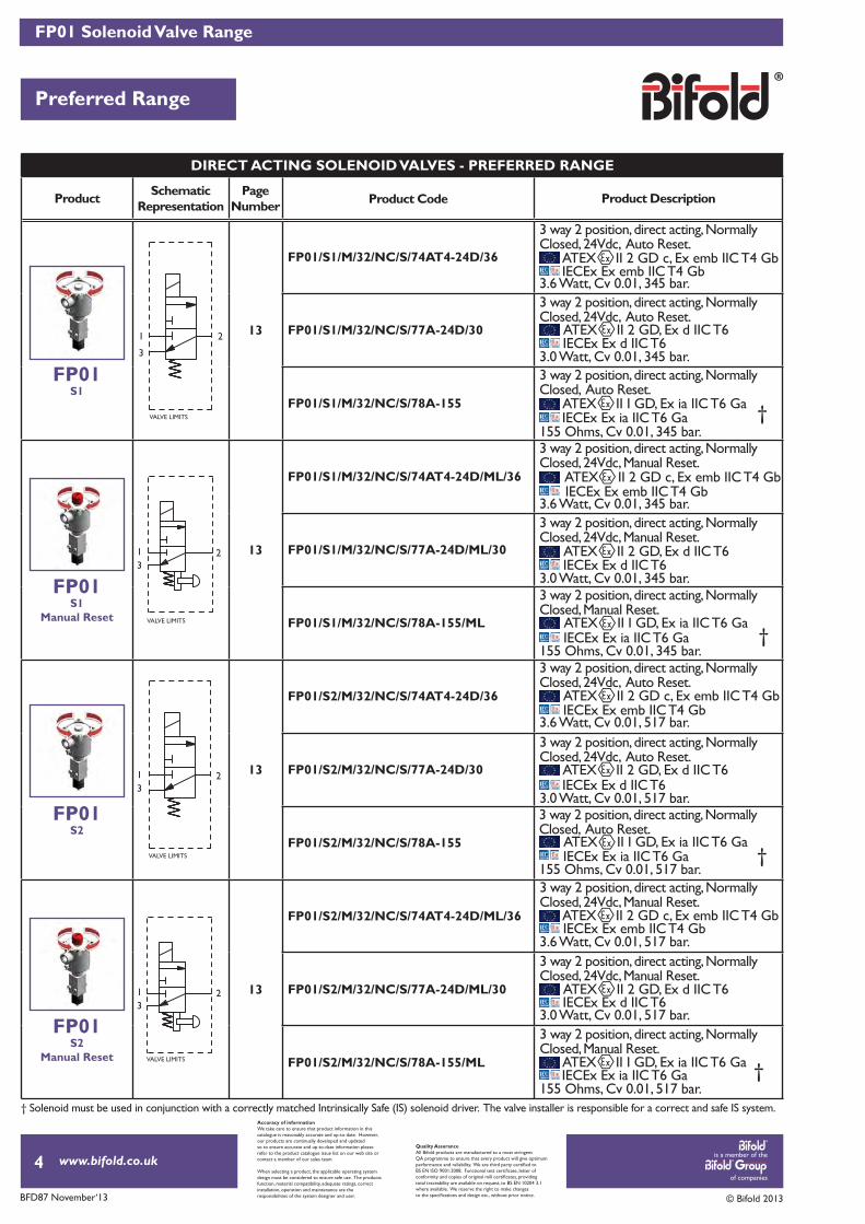
DIRECT ACTING SOLENOID VALVES - PREFERRED RANGE
FP01S1
FP01S1
Manual Reset
FP01S2
FP01S2
Manual Reset
†
FP01/S1/M/32/NC/S/74AT4-24D/36
FP01/S2/M/32/NC/S/74AT4-24D/36
FP01/S1/M/32/NC/S/77A-24D/30
FP01/S2/M/32/NC/S/77A-24D/30
FP01/S1/M/32/NC/S/78A-155
FP01/S2/M/32/NC/S/78A-155
FP01/S1/M/32/NC/S/74AT4-24D/ML/36
FP01/S2/M/32/NC/S/74AT4-24D/ML/36
FP01/S1/M/32/NC/S/77A-24D/ML/30
FP01/S2/M/32/NC/S/77A-24D/ML/30
FP01/S1/M/32/NC/S/78A-155/ML
FP01/S2/M/32/NC/S/78A-155/ML
ATEX II 2 GD c, Ex emb IIC T4 Gb
ATEX II 2 GD c, Ex emb IIC T4 Gb
ATEX II 2 GD, Ex d IIC T6
ATEX II 2 GD, Ex d IIC T6
ATEX II I GD, Ex ia IIC T6 Ga
ATEX II I GD, Ex ia IIC T6 Ga
IECEx Ex emb IIC T4 Gb
IECEx Ex emb IIC T4 Gb
IECEx Ex d IIC T6
IECEx Ex d IIC T6
IECEx Ex ia IIC T6 Ga
IECEx Ex ia IIC T6 Ga
3.6 Watt, Cv 0.01, 345 bar.
3.6 Watt, Cv 0.01, 517 bar.
3.0 Watt, Cv 0.01, 345 bar.
3.0 Watt, Cv 0.01, 517 bar.
3 way 2 position, direct acting, Normally Closed, 24Vdc, Auto Reset.
3 way 2 position, direct acting, Normally Closed, 24Vdc, Auto Reset.
3 way 2 position, direct acting, Normally Closed, Auto Reset.
3 way 2 position, direct acting, Normally Closed, 24Vdc, Auto Reset.
3 way 2 position, direct acting, Normally Closed, 24Vdc, Auto Reset.
3 way 2 position, direct acting, Normally Closed, Auto Reset.
ATEX II 2 GD c, Ex emb IIC T4 Gb
ATEX II 2 GD c, Ex emb IIC T4 Gb
3.6 Watt, Cv 0.01, 345 bar.
3.6 Watt, Cv 0.01, 517 bar.
3 way 2 position, direct acting, Normally Closed, 24Vdc, Manual Reset.
3 way 2 position, direct acting, Normally Closed, 24Vdc, Manual Reset.
3 way 2 position, direct acting, Normally Closed, Manual Reset.
3 way 2 position, direct acting, Normally Closed, 24Vdc, Manual Reset.
3 way 2 position, direct acting, Normally Closed, 24Vdc, Manual Reset.
3 way 2 position, direct acting, Normally Closed, Manual Reset.
ATEX II 2 GD, Ex d IIC T6
ATEX II 2 GD, Ex d IIC T6
IECEx Ex d IIC T6
IECEx Ex d IIC T6
3.0 Watt, Cv 0.01, 345 bar.
3.0 Watt, Cv 0.01, 517 bar.
†
†
†
ATEX II I GD, Ex ia IIC T6 Ga
ATEX II I GD, Ex ia IIC T6 Ga
IECEx Ex ia IIC T6 Ga
IECEx Ex ia IIC T6 Ga
155 Ohms, Cv 0.01, 345 bar.
155 Ohms, Cv 0.01, 517 bar.
155 Ohms, Cv 0.01, 345 bar.
155 Ohms, Cv 0.01, 517 bar.
IECEx Ex emb IIC T4 Gb
IECEx Ex emb IIC T4 Gb
† Solenoid must be used in conjunction with a correctly matched Intrinsically Safe (IS) solenoid driver. The valve installer is responsible for a correct and safe IS system.
VALVE LIMITS
1 2
3
VALVE LIMITS
1 23
VALVE LIMITS
1 23
VALVE LIMITS
1 23

is a member of the
of companies
www.bifold.co.uk
BFD87 November‘13 © Bifold 2013
FP01 Solenoid Valve Range
Preferred Range
5
Accuracy of informationWe take care to ensure that product information in thiscatalogue is reasonably accurate and up-to-date. However,our products are continually developed and updatedso to ensure accurate and up-to-date information pleaserefer to the product catalogue issue list on our web site orcontact a member of our sales team.
When selecting a product, the applicable operating systemdesign must be considered to ensure safe use. The productsfunction, material compatibility, adequate ratings, correctinstallation, operation and maintenance are theresponsibilities of the system designer and user.
Quality AssuranceAll Bifold products are manufactured to a most stringentQA programme to ensure that every product will give optimum
total traceability are available on request, to BS EN 10204 3.1where available. We reserve the right to make changes
Product SchematicRepresentation
PageNumber Product Code Product Description
13
13
DIRECT ACTING SOLENOID VALVES - PREFERRED RANGE
FP01S3
FP01S3
Manual Reset
FP01/S3/M/32/NC/S/74AT4-24D/36
FP01/S3/M/32/NC/S/77A-24D/30
FP01/S3/M/32/NC/S/78A-155
FP01/S3/M/32/NC/S/74AT4-24D/ML/36
FP01/S3/M/32/NC/S/77A-24D/ML/30
FP01/S3/M/32/NC/S/78A-155/ML
ATEX II 2 GD c, Ex emb IIC T4 GbIECEx Ex emb IIC T4 Gb
3.6 Watt, Cv 0.01, 690 bar.
3 way 2 position, direct acting, Normally Closed, 24Vdc, Auto Reset.
ATEX II 2 GD, Ex d IIC T6IECEx Ex d IIC T6
3.0 Watt, Cv 0.01, 690 bar.
3 way 2 position, direct acting, Normally Closed, 24Vdc, Auto Reset.
3 way 2 position, direct acting, Normally Closed, 24Vdc, Manual Reset.
ATEX II 2 GD, Ex d IIC T6IECEx Ex d IIC T6
3.0 Watt, Cv 0.01, 690 bar.
†ATEX II I GD, Ex ia IIC T6 GaIECEx Ex ia IIC T6 Ga
3 way 2 position, direct acting, Normally Closed, Auto Reset.
155 Ohms, Cv 0.01, 690 bar.
3 way 2 position, direct acting, Normally Closed, Manual Reset.
†ATEX II I GD, Ex ia IIC T6 GaIECEx Ex ia IIC T6 Ga
155 Ohms, Cv 0.01, 690 bar.
ATEX II 2 GD c, Ex emb IIC T4 Gb
3.6 Watt, Cv 0.01, 690 bar.
3 way 2 position, direct acting, Normally Closed, 24Vdc, Manual Reset.
IECEx Ex emb IIC T4 Gb
† Solenoid must be used in conjunction with a correctly matched Intrinsically Safe (IS) solenoid driver. The valve installer is responsible for a correct and safe IS system.
VALVE LIMITS
1 23
VALVE LIMITS
1 23
is a member of the
of companies
www.bifold.co.uk
BFD87 November‘13 © Bifold 2013
6
Accuracy of informationWe take care to ensure that product information in thiscatalogue is reasonably accurate and up-to-date. However,our products are continually developed and updatedso to ensure accurate and up-to-date information pleaserefer to the product catalogue issue list on our web site orcontact a member of our sales team.
When selecting a product, the applicable operating systemdesign must be considered to ensure safe use. The productsfunction, material compatibility, adequate ratings, correctinstallation, operation and maintenance are theresponsibilities of the system designer and user.
Quality AssuranceAll Bifold products are manufactured to a most stringentQA programme to ensure that every product will give optimum
total traceability are available on request, to BS EN 10204 3.1where available. We reserve the right to make changes
Product SchematicRepresentation
PageNumber Product Code Product Description
14
14
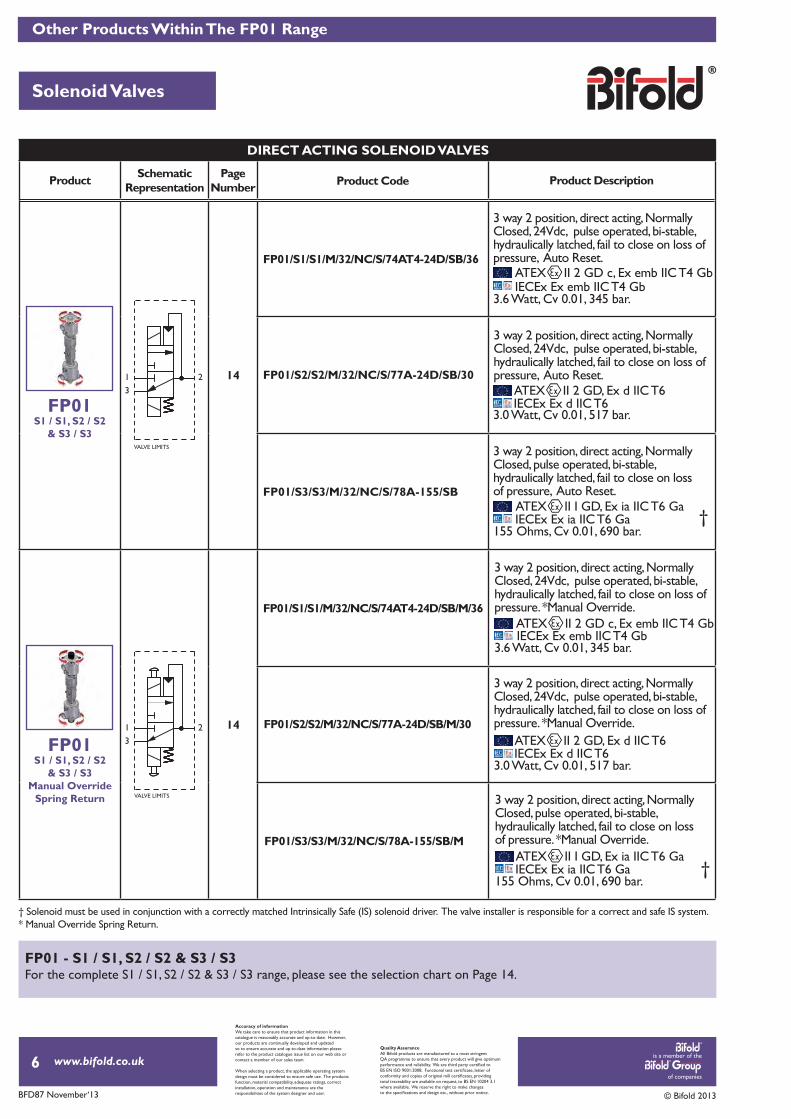
DIRECT ACTING SOLENOID VALVES
FP01/S2/S2/M/32/NC/S/77A-24D/SB/30
FP01/S3/S3/M/32/NC/S/78A-155/SB
FP01/S2/S2/M/32/NC/S/77A-24D/SB/M/30
FP01/S3/S3/M/32/NC/S/78A-155/SB/M
ATEX II 2 GD, Ex d IIC T6IECEx Ex d IIC T6
3.0 Watt, Cv 0.01, 517 bar.
3 way 2 position, direct acting, Normally Closed, 24Vdc, pulse operated, bi-stable, hydraulically latched, fail to close on loss of pressure, Auto Reset.
3 way 2 position, direct acting, Normally Closed, 24Vdc, pulse operated, bi-stable, hydraulically latched, fail to close on loss of pressure. *Manual Override.
ATEX II 2 GD, Ex d IIC T6IECEx Ex d IIC T6
3.0 Watt, Cv 0.01, 517 bar.
†ATEX II I GD, Ex ia IIC T6 GaIECEx Ex ia IIC T6 Ga
3 way 2 position, direct acting, Normally Closed, pulse operated, bi-stable, hydraulically latched, fail to close on loss of pressure, Auto Reset.
155 Ohms, Cv 0.01, 690 bar.
3 way 2 position, direct acting, Normally Closed, pulse operated, bi-stable, hydraulically latched, fail to close on loss of pressure. *Manual Override.
†ATEX II I GD, Ex ia IIC T6 GaIECEx Ex ia IIC T6 Ga
155 Ohms, Cv 0.01, 690 bar.
Other Products Within The FP01 Range
Solenoid Valves
FP01S1 / S1, S2 / S2
& S3 / S3
FP01S1 / S1, S2 / S2
& S3 / S3Manual Override
Spring Return
FP01/S1/S1/M/32/NC/S/74AT4-24D/SB/36
FP01/S1/S1/M/32/NC/S/74AT4-24D/SB/M/36
ATEX II 2 GD c, Ex emb IIC T4 GbIECEx Ex emb IIC T4 Gb
3.6 Watt, Cv 0.01, 345 bar.
3 way 2 position, direct acting, Normally Closed, 24Vdc, pulse operated, bi-stable, hydraulically latched, fail to close on loss of pressure, Auto Reset.
ATEX II 2 GD c, Ex emb IIC T4 Gb
3.6 Watt, Cv 0.01, 345 bar.
3 way 2 position, direct acting, Normally Closed, 24Vdc, pulse operated, bi-stable, hydraulically latched, fail to close on loss of pressure. *Manual Override.
IECEx Ex emb IIC T4 Gb
† Solenoid must be used in conjunction with a correctly matched Intrinsically Safe (IS) solenoid driver. The valve installer is responsible for a correct and safe IS system. * Manual Override Spring Return.
FP01 - S1 / S1, S2 / S2 & S3 / S3 For the complete S1 / S1, S2 / S2 & S3 / S3 range, please see the selection chart on Page 14.
1 23
VALVE LIMITS
1 23
VALVE LIMITS
is a member of the
of companies
www.bifold.co.uk
BFD87 November‘13 © Bifold 2013
Overview
7
Accuracy of informationWe take care to ensure that product information in thiscatalogue is reasonably accurate and up-to-date. However,our products are continually developed and updatedso to ensure accurate and up-to-date information pleaserefer to the product catalogue issue list on our web site orcontact a member of our sales team.
When selecting a product, the applicable operating systemdesign must be considered to ensure safe use. The productsfunction, material compatibility, adequate ratings, correctinstallation, operation and maintenance are theresponsibilities of the system designer and user.
Quality AssuranceAll Bifold products are manufactured to a most stringentQA programme to ensure that every product will give optimum
total traceability are available on request, to BS EN 10204 3.1where available. We reserve the right to make changes
Materials of Construction
Technical Data
Product Options
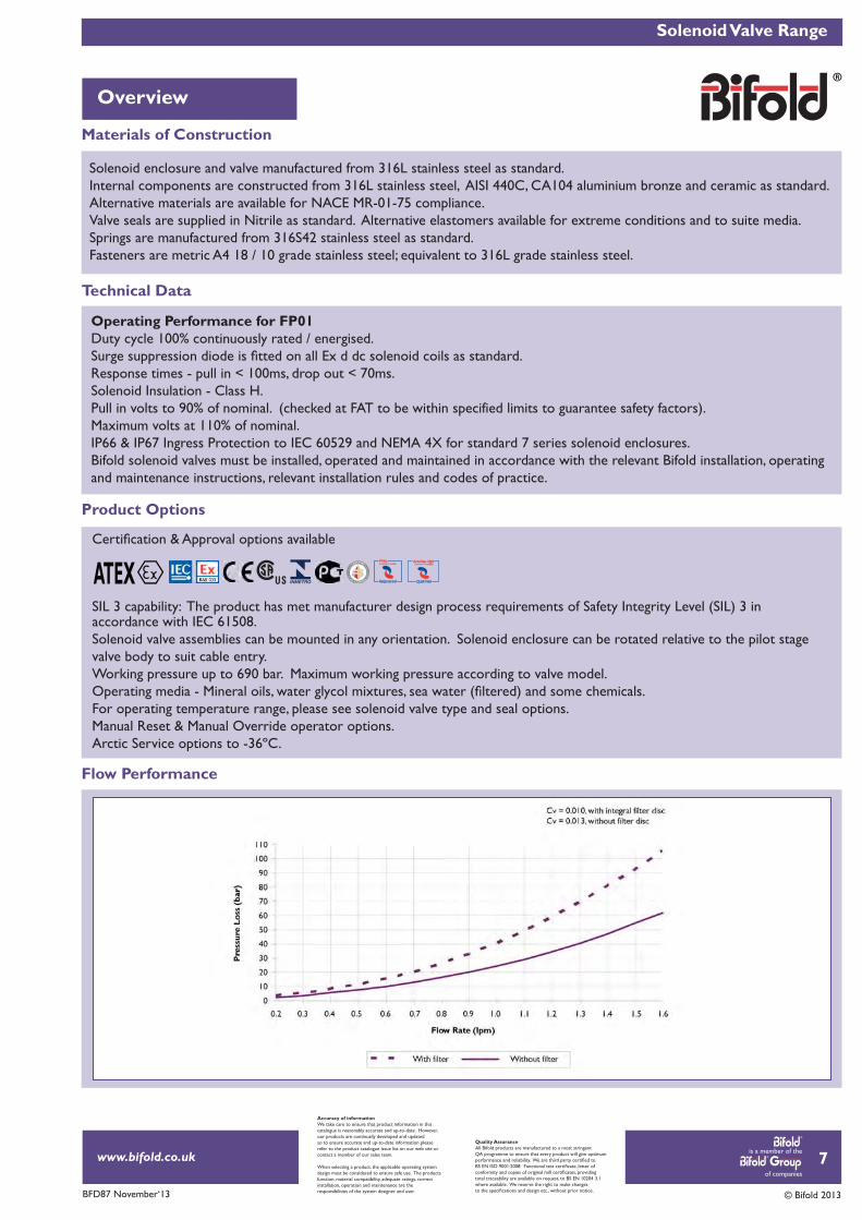
Solenoid enclosure and valve manufactured from 316L stainless steel as standard.Internal components are constructed from 316L stainless steel, AISI 440C, CA104 aluminium bronze and ceramic as standard.Alternative materials are available for NACE MR-01-75 compliance.Valve seals are supplied in Nitrile as standard. Alternative elastomers available for extreme conditions and to suite media. Springs are manufactured from 316S42 stainless steel as standard.Fasteners are metric A4 18 / 10 grade stainless steel; equivalent to 316L grade stainless steel.
Solenoid Valve Range
SIL 3 capability: The product has met manufacturer design process requirements of Safety Integrity Level (SIL) 3 in accordance with IEC 61508.Solenoid valve assemblies can be mounted in any orientation. Solenoid enclosure can be rotated relative to the pilot stage valve body to suit cable entry.Working pressure up to 690 bar. Maximum working pressure according to valve model.
For operating temperature range, please see solenoid valve type and seal options.Manual Reset & Manual Override operator options. Arctic Service options to -36ºC.
ATEX Registered
Operating Performance for FP01Duty cycle 100% continuously rated / energised.
Response times - pull in < 100ms, drop out < 70ms.Solenoid Insulation - Class H. Pull in volts to 90% of nominal. (checked at FAT to be within specified limits to guarantee safety factors). Maximum volts at 110% of nominal.IP66 & IP67 Ingress Protection to IEC 60529 and NEMA 4X for standard 7 series solenoid enclosures.Bifold solenoid valves must be installed, operated and maintained in accordance with the relevant Bifold installation, operatingand maintenance instructions, relevant installation rules and codes of practice.
Flow Performance
is a member of the
of companies
www.bifold.co.uk
BFD87 November‘13 © Bifold 2013
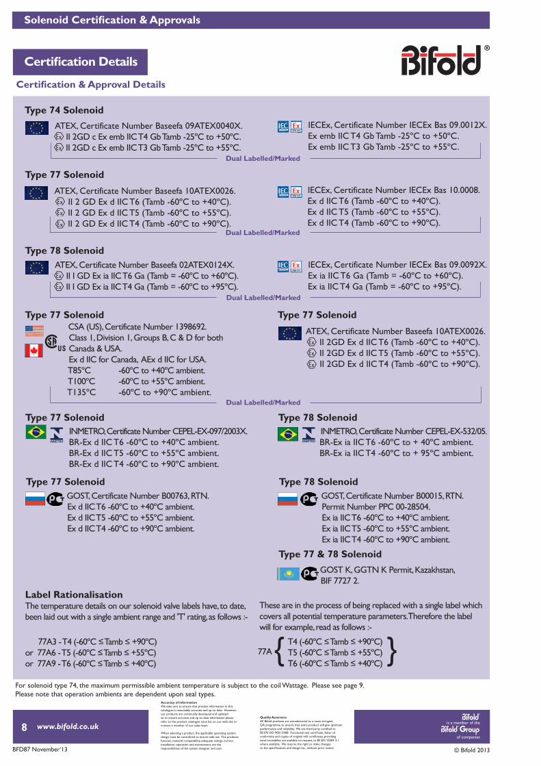
Type 77 Solenoid
Type 74 Solenoid
Type 78 Solenoid
Type 77 Solenoid
Type 78 Solenoid
Type 77 Solenoid
Type 77 & 78 Solenoid
Type 78 Solenoid
Type 77 Solenoid
Type 77 Solenoid
IECEx, Certificate Number IECEx Bas 10.0008. Ex d IIC T6 (Tamb -60ºC to +40ºC). Ex d IIC T5 (Tamb -60ºC to +55ºC). Ex d IIC T4 (Tamb -60ºC to +90ºC).
IECEx, Certificate Number IECEx Bas 09.0012X. Ex emb IIC T4 Gb Tamb -25ºC to +50ºC. Ex emb IIC T3 Gb Tamb -25ºC to +55ºC.
IECEx, Certificate Number IECEx Bas 09.0092X. Ex ia IIC T6 Ga (Tamb = -60ºC to +60ºC). Ex ia IIC T4 Ga (Tamb = -60ºC to +95ºC).
INMETRO, Certificate Number CEPEL-EX-097/2003X. BR-Ex d IIC T6 -60ºC to +40ºC ambient. BR-Ex d IIC T5 -60ºC to +55ºC ambient. BR-Ex d IIC T4 -60ºC to +90ºC ambient.
ATEX, Certificate Number Baseefa 10ATEX0026. II 2 GD Ex d IIC T6 (Tamb -60ºC to +40ºC). II 2 GD Ex d IIC T5 (Tamb -60ºC to +55ºC). II 2 GD Ex d IIC T4 (Tamb -60ºC to +90ºC).
ATEX, Certificate Number Baseefa 10ATEX0026. II 2GD Ex d IIC T6 (Tamb -60ºC to +40ºC). II 2GD Ex d IIC T5 (Tamb -60ºC to +55ºC). II 2GD Ex d IIC T4 (Tamb -60ºC to +90ºC).
ATEX, Certificate Number Baseefa 09ATEX0040X. II 2GD c Ex emb IIC T4 Gb Tamb -25ºC to +50ºC. II 2GD c Ex emb IIC T3 Gb Tamb -25ºC to +55ºC.
ATEX, Certificate Number Baseefa 02ATEX0124X. II I GD Ex ia IIC T6 Ga (Tamb = -60ºC to +60ºC). II I GD Ex ia IIC T4 Ga (Tamb = -60ºC to +95ºC).
INMETRO, Certificate Number CEPEL-EX-532/05. BR-Ex ia IIC T6 -60ºC to + 40ºC ambient. BR-Ex ia IIC T4 -60ºC to + 95ºC ambient.
GOST, Certificate Number B00763, RTN. Ex d IIC T6 -60ºC to +40ºC ambient. Ex d IIC T5 -60ºC to +55ºC ambient. Ex d IIC T4 -60ºC to +90ºC ambient.
GOST K, GGTN K Permit, Kazakhstan, BIF 7727 2.
GOST, Certificate Number B00015, RTN. Permit Number PPC 00-28504. Ex ia IIC T6 -60ºC to +40ºC ambient. Ex ia IIC T5 -60ºC to +55ºC ambient. Ex ia IIC T4 -60ºC to +90ºC ambient.
CSA (US), Certificate Number 1398692. Class 1, Division 1, Groups B, C & D for both Canada & USA. Ex d IIC for Canada, AEx d IIC for USA. T85ºC -60ºC to +40ºC ambient. T100ºC -60ºC to +55ºC ambient. T135ºC -60ºC to +90ºC ambient.
Dual Labelled/Marked
Dual Labelled/Marked
Dual Labelled/Marked
Dual Labelled/Marked
For solenoid type 74, the maximum permissible ambient temperature is subject to the coil Wattage. Please see page 9. Please note that operation ambients are dependent upon seal types.
Label RationalisationThe temperature details on our solenoid valve labels have, to date, been laid out with a single ambient range and 'T' rating, as follows :-
or 77A6 - T5 or 77A9 - T6
These are in the process of being replaced with a single label which covers all potential temperature parameters. Therefore the label will for example, read as follows :-
T5 T6
77A{ {
8
Accuracy of informationWe take care to ensure that product information in thiscatalogue is reasonably accurate and up-to-date. However,our products are continually developed and updatedso to ensure accurate and up-to-date information pleaserefer to the product catalogue issue list on our web site orcontact a member of our sales team.
When selecting a product, the applicable operating systemdesign must be considered to ensure safe use. The productsfunction, material compatibility, adequate ratings, correctinstallation, operation and maintenance are theresponsibilities of the system designer and user.
Quality AssuranceAll Bifold products are manufactured to a most stringentQA programme to ensure that every product will give optimum
total traceability are available on request, to BS EN 10204 3.1where available. We reserve the right to make changes
is a member of the
of companies
www.bifold.co.uk
BFD87 November‘13 © Bifold 2013
Solenoid Valve Product Options
Port Connections
Solenoid Coil Spare
Product Weights
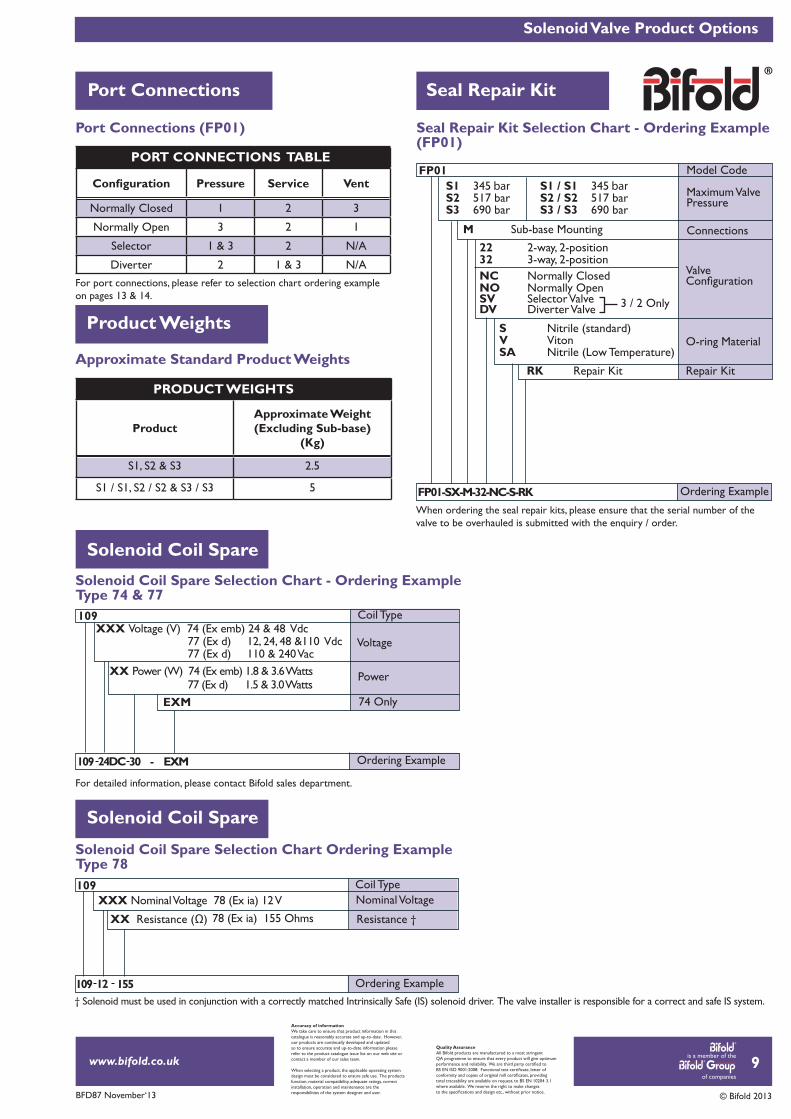
Port Connections (FP01)
Solenoid Coil Spare Selection Chart - Ordering ExampleType 74 & 77
Approximate Standard Product Weights
For port connections, please refer to selection chart ordering example on pages 13 & 14.
Pressure Service Vent
Normally Closed 1 2 3
Normally Open 3 2 1
Selector 1 & 3 2 N/A
Diverter 2 1 & 3 N/A
ProductApproximate Weight (Excluding Sub-base)
(Kg)
S1, S2 & S3 2.5
S1 / S1, S2 / S2 & S3 / S3 5
109
109
Voltage
Coil Type
Coil Type
Power
74 Only
Resistance †
Nominal Voltage
Ordering Example
Ordering Example
109
109
30 - EXM
155
24DC
12
XXX Voltage (V) 74 (Ex emb) 24 & 48 Vdc
EXM
XXX Nominal Voltage 78 (Ex ia) 12 V
XX Power (W) 74 (Ex emb) 1.8 & 3.6 Watts
Seal Repair Kit
77 (Ex d) 12, 24, 48 &110 Vdc
78 (Ex ia) 155 Ohms
77 (Ex d) 110 & 240 Vac
77 (Ex d) 1.5 & 3.0 Watts
PORT CONNECTIONS TABLE
PRODUCT WEIGHTS
For detailed information, please contact Bifold sales department.
Solenoid Coil Spare
Solenoid Coil Spare Selection Chart Ordering Example Type 78
† Solenoid must be used in conjunction with a correctly matched Intrinsically Safe (IS) solenoid driver. The valve installer is responsible for a correct and safe IS system.
9
Accuracy of informationWe take care to ensure that product information in thiscatalogue is reasonably accurate and up-to-date. However,our products are continually developed and updatedso to ensure accurate and up-to-date information pleaserefer to the product catalogue issue list on our web site orcontact a member of our sales team.
When selecting a product, the applicable operating systemdesign must be considered to ensure safe use. The productsfunction, material compatibility, adequate ratings, correctinstallation, operation and maintenance are theresponsibilities of the system designer and user.
Quality AssuranceAll Bifold products are manufactured to a most stringentQA programme to ensure that every product will give optimum
total traceability are available on request, to BS EN 10204 3.1where available. We reserve the right to make changes
XX
Seal Repair Kit Selection Chart - Ordering Example(FP01)
Model Code
Ordering Example
When ordering the seal repair kits, please ensure that the serial number of the valve to be overhauled is submitted with the enquiry / order.
FP01
FP01-SX-M-32-NC-S-RK
S1 345 barS2 517 bar S3 690 bar
RK Repair Kit
S1 / S1 345 barS2 / S2 517 bar S3 / S3 690 bar
M Sub-base Mounting
NC Normally ClosedNO Normally Open
22 2-way, 2-position 32 3-way, 2-position
S Nitrile (standard) V Viton SA Nitrile (Low Temperature)
3 / 2 OnlySV Selector ValveDV Diverter Valve
Connections
Maximum Valve Pressure
Valve
O-ring Material
Repair Kit
is a member of the
of companies
www.bifold.co.uk
BFD87 November‘13 © Bifold 2013
Ex emb Options
FP01 Solenoid Options
10
Accuracy of informationWe take care to ensure that product information in thiscatalogue is reasonably accurate and up-to-date. However,our products are continually developed and updatedso to ensure accurate and up-to-date information pleaserefer to the product catalogue issue list on our web site orcontact a member of our sales team.
When selecting a product, the applicable operating systemdesign must be considered to ensure safe use. The productsfunction, material compatibility, adequate ratings, correctinstallation, operation and maintenance are theresponsibilities of the system designer and user.
Quality AssuranceAll Bifold products are manufactured to a most stringentQA programme to ensure that every product will give optimum
total traceability are available on request, to BS EN 10204 3.1where available. We reserve the right to make changes
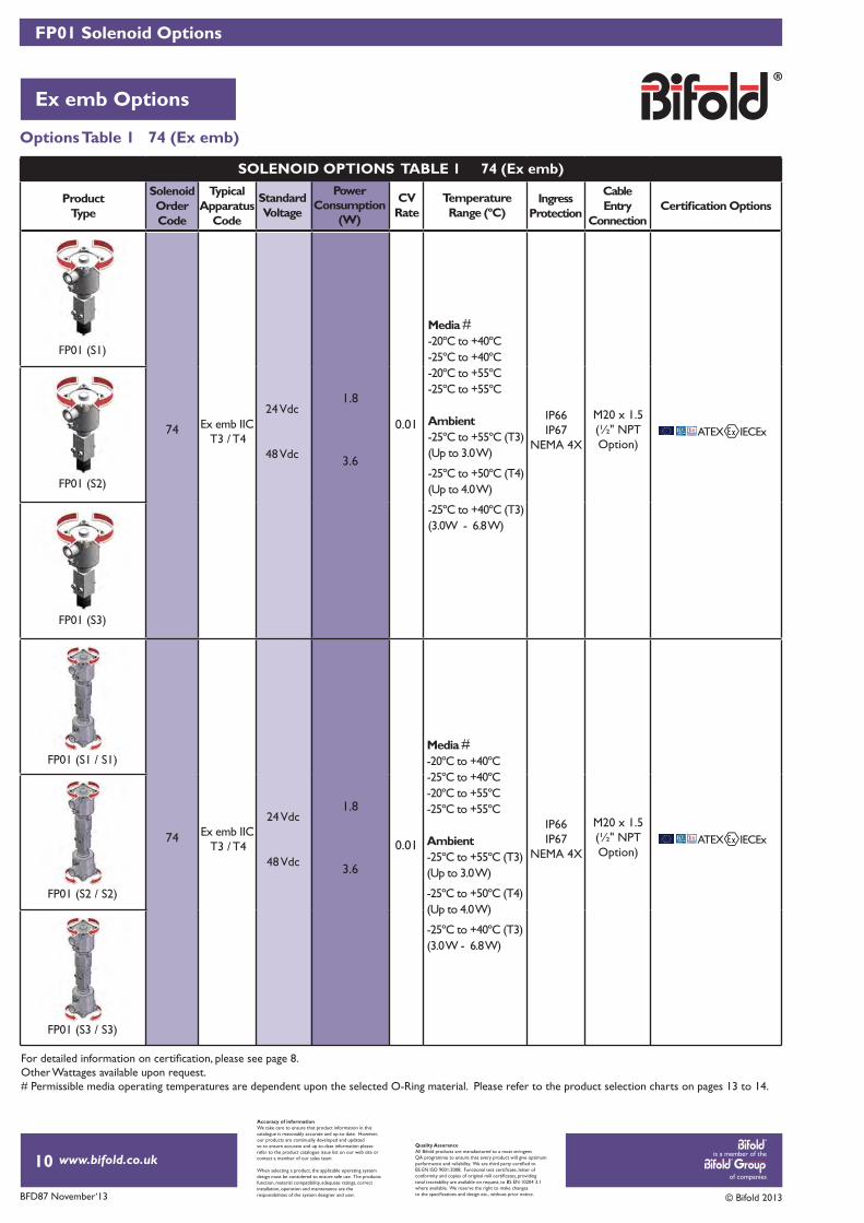
Media #-20ºC to +40ºC-25ºC to +40ºC-20ºC to +55ºC-25ºC to +55ºC
Ambient-25ºC to +55ºC (T3)(Up to 3.0 W)
-25ºC to +50ºC (T4)(Up to 4.0 W)
-25ºC to +40ºC (T3)(3.0W - 6.8 W)
Media #-20ºC to +40ºC-25ºC to +40ºC-20ºC to +55ºC-25ºC to +55ºC
Ambient-25ºC to +55ºC (T3)(Up to 3.0 W)
-25ºC to +50ºC (T4)(Up to 4.0 W)
-25ºC to +40ºC (T3)(3.0 W - 6.8 W)
IP66IP67
NEMA 4X
IP66IP67
NEMA 4X
M20 x 1.5(½" NPT Option)
M20 x 1.5(½" NPT Option)
ProductType
SolenoidOrderCode
TypicalApparatus
Code
IngressProtection
CableEntry
Connection
74
1.8
3.6
0.01
74
1.8
3.6
0.01
ATEX IECEx
ATEX IECEx
Options Table 1 74 (Ex emb)
Other Wattages available upon request.# Permissible media operating temperatures are dependent upon the selected O-Ring material. Please refer to the product selection charts on pages 13 to 14.
Standard Voltage
CVRate
PowerConsumption
(W)
TemperatureRange (ºC)
Ex emb IIC T3 / T4
Ex emb IIC T3 / T4
24 Vdc
48 Vdc
24 Vdc
48 Vdc
FP01 (S1)
FP01 (S2)
FP01 (S3)
FP01 (S1 / S1)
FP01 (S2 / S2)
FP01 (S3 / S3)
SOLENOID OPTIONS TABLE 1 74 (Ex emb)
is a member of the
of companies
www.bifold.co.uk
BFD87 November‘13 © Bifold 2013
Ex d Options
FP01 Solenoid Options
11
Accuracy of informationWe take care to ensure that product information in thiscatalogue is reasonably accurate and up-to-date. However,our products are continually developed and updatedso to ensure accurate and up-to-date information pleaserefer to the product catalogue issue list on our web site orcontact a member of our sales team.
When selecting a product, the applicable operating systemdesign must be considered to ensure safe use. The productsfunction, material compatibility, adequate ratings, correctinstallation, operation and maintenance are theresponsibilities of the system designer and user.
Quality AssuranceAll Bifold products are manufactured to a most stringentQA programme to ensure that every product will give optimum
total traceability are available on request, to BS EN 10204 3.1where available. We reserve the right to make changes
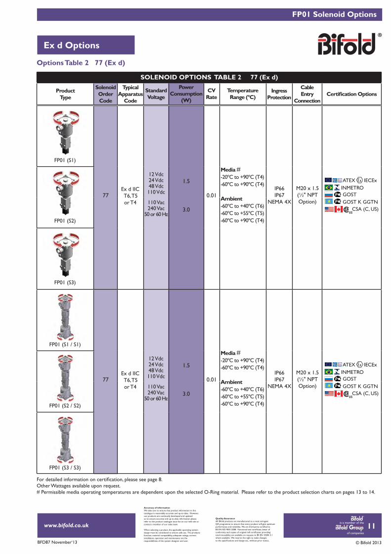
IP66IP67
NEMA 4X
IP66IP67
NEMA 4X
M20 x 1.5(½" NPT Option)
M20 x 1.5(½" NPT Option)
ATEX IECExINMETROGOST
CSA (C, US)GOST K GGTN
ATEX IECExINMETROGOST
CSA (C, US)GOST K GGTN
ProductType
SolenoidOrderCode
TypicalApparatus
Code
IngressProtection
CableEntry
Connection
77
1.5
3.0
0.01
77
1.5
3.0
0.01
Other Wattages available upon request.# Permissible media operating temperatures are dependent upon the selected O-Ring material. Please refer to the product selection charts on pages 13 to 14.
Options Table 2 77 (Ex d)
FP01 (S1)
FP01 (S2)
FP01 (S3)
FP01 (S1 / S1)
FP01 (S2 / S2)
FP01 (S3 / S3)
Standard Voltage
CVRate
PowerConsumption
(W)
TemperatureRange (ºC)
Ex d IIC T6, T5or T4
Ex d IIC T6, T5or T4
12 Vdc24 Vdc48 Vdc110 Vdc
12 Vdc24 Vdc48 Vdc110 Vdc
110 Vac240 Vac
50 or 60 Hz
110 Vac240 Vac
50 or 60 Hz
Media #-20ºC to +90ºC (T4)-60ºC to +90ºC (T4)
Ambient-60ºC to +40ºC (T6)-60ºC to +55ºC (T5)-60ºC to +90ºC (T4)
Media #-20ºC to +90ºC (T4)-60ºC to +90ºC (T4)
Ambient-60ºC to +40ºC (T6)-60ºC to +55ºC (T5)-60ºC to +90ºC (T4)
SOLENOID OPTIONS TABLE 2 77 (Ex d)
is a member of the
of companies
www.bifold.co.uk
BFD87 November‘13 © Bifold 2013
FP01 Solenoid Options
Ex ia Options
12
Accuracy of informationWe take care to ensure that product information in thiscatalogue is reasonably accurate and up-to-date. However,our products are continually developed and updatedso to ensure accurate and up-to-date information pleaserefer to the product catalogue issue list on our web site orcontact a member of our sales team.
When selecting a product, the applicable operating systemdesign must be considered to ensure safe use. The productsfunction, material compatibility, adequate ratings, correctinstallation, operation and maintenance are theresponsibilities of the system designer and user.
Quality AssuranceAll Bifold products are manufactured to a most stringentQA programme to ensure that every product will give optimum
total traceability are available on request, to BS EN 10204 3.1where available. We reserve the right to make changes
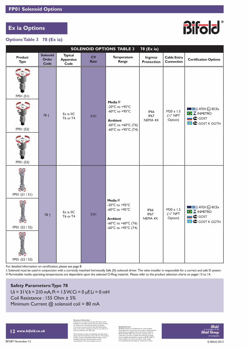
Options Table 3 78 (Ex ia)
† Solenoid must be used in conjunction with a correctly matched Intrinsically Safe (IS) solenoid driver. The valve installer is responsible for a correct and safe IS system.# Permissible media operating temperatures are dependent upon the selected O-Ring material. Please refer to the product selection charts on pages 13 to 14.
ProductType
TypicalApparatus
Code
IngressProtection
Cable EntryConnection
78 †
0.01
0.01
Ex ia IIC T6 or T4
Ex ia IIC T6 or T4
78 †IP66IP67
NEMA 4X
IP66IP67
NEMA 4X
M20 x 1.5(½" NPT Option)
M20 x 1.5(½" NPT Option)
TemperatureRange
Solenoid OrderCode
CVRate
Media #-20ºC to +95ºC-60ºC to +95ºC
Ambient-60ºC to +60ºC (T6)-60ºC to +95ºC (T4)
Media #-20ºC to +95ºC-60ºC to +95ºC
Ambient-60ºC to +60ºC (T6)-60ºC to +95ºC (T4)
SOLENOID OPTIONS TABLE 3 78 (Ex ia)
GOST K GGTN
INMETROATEX IECEx
GOST
GOST K GGTN
INMETROATEX IECEx
GOST
FP01 (S1)
FP01 (S2)
FP01 (S3)
FP01 (S2 / S2)
FP01 (S3 / S3)
FP01 (S1 / S1)
Safety Parameters: Type 78Ui = 31 V, Ii = 210 mA, Pi = 1.5 W, Ci = 0 μF, Li = 0 mHCoil Resistance : 155 Ohm ± 5%Minimum Current @ solenoid coil = 80 mA
is a member of the
of companies
www.bifold.co.uk
BFD87 November‘13 © Bifold 2013
FP01 - S1, S2 & S3 Selection Chart
FP01 (S1, S2 & S3)
13
Accuracy of informationWe take care to ensure that product information in thiscatalogue is reasonably accurate and up-to-date. However,our products are continually developed and updatedso to ensure accurate and up-to-date information pleaserefer to the product catalogue issue list on our web site orcontact a member of our sales team.
When selecting a product, the applicable operating systemdesign must be considered to ensure safe use. The productsfunction, material compatibility, adequate ratings, correctinstallation, operation and maintenance are theresponsibilities of the system designer and user.
Quality AssuranceAll Bifold products are manufactured to a most stringentQA programme to ensure that every product will give optimum
total traceability are available on request, to BS EN 10204 3.1where available. We reserve the right to make changes
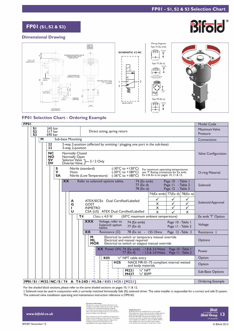
Dimensional Drawing
FP01 Selection Chart - Ordering ExampleFP01 Model Code
Connections
Maximum Valve Pressure
O-ring Material
Solenoid Approval
Voltage
Ex emb 'T' Option
Solenoid
Option
Option
Sub-Base Options
Options
Power
Resistance †
Ordering Example
XX Refer to solenoid options tables.
XXX Voltage, refer to Solenoid option tables. XX
S1 345 barS2 517 barS3 690 bar
FP01 / S1 / M/32 / NC / 74 A T4-24D / ML/ K85 / H2S /S / 36 /
M Sub-base Mounting
Direct acting, spring return
NC Normally ClosedNO Normally Open
22 2-way, 2-position (effected by omitting / plugging one port in the sub-base)32 3-way, 2-position
S Nitrile (standard) V Viton SA Nitrile (Low Temperature)
XX Power (W)
78 (Ex ia)
74 (Ex emb) Page 10 - Table 1
74 (Ex emb) Page 10 - Table 1
77 (Ex d)
77 (Ex d) Page 11 - Table 2
77 (Ex d) Page 11 - Table 2
78 (Ex ia) Page 12 - Table 3
74 (Ex emb)
K85 ½" NPT cable entry
T4 Class ≤ 4.0 W (50ºC maximum ambient temperature)
M Electrical to switch or temporary manual overrideML Electrical and manual requiredMOR Electrical to switch or stayput manual override
For maximum operating temperaturessee 'T' Rating Limitations for Ex emb,Ex d & Ex ia on pages 10, 11 & 12.
3 / 2 OnlySV Selector ValveDV Diverter Valve
(-30ºC to +130ºC)(-20ºC to +180ºC)(-36ºC to +180ºC)
AG GOST I INMETROU CSA (US) ATEX Dual Certified/Labelled
74(Ex emb) 77(Ex d) 78(Ex ia)
xx
x x
H2S NACE MR-01-75 compliant internal wetted and body materials
FACTORY SETADJUSTEMENT
M20 x 1.5PCABLE ENTRY
PUSH TORESET OROVERRIDE(OPTION)
3
2
1
12
3
VALVE SHOWN AS NORMALLY CLOSED
REQUIRED FIXING HOLESM6 x 1P x 10 DP
2 PLACES55
,5
20,8
25,4
198
25(M
& M
L)
50,8
1424
,5
22,5
9
167,
5
EXTERNALEARTH
SOLENOID ENCLOSURE MAY BEROTATED THRO' 360 IF°
UNRESTRICTED
2 x S.H.C.S.M6 x 40 LG
SUB-BASE(OPTION)
For the shaded block sections, please refer to the same shaded sections on pages 10, 11 & 12.† Solenoid must be used in conjunction with a correctly matched Intrinsically Safe (IS) solenoid driver. The valve installer is responsible for a correct and safe IS system.The solenoid valve installation operating and maintenance instruction reference is OP0165.
VALVE LIMITS
SCHEMATIC 3/2 NC
1 2
3
Type 74 (Ex emb)
Type 77 (Ex d)
Voltage can be applied in either direction
WINDING CASESOLENOID
DC VOLTAGE
Wiring Diagrams
+
WINDING
CASESOLENOID
DC VOLTAGE -
+
WINDING
CASESOLENOID
DC VOLTAGE -
WINDING
CASESOLENOID
AC VOLTAGE
Type 78 (Ex ia)
Page 10 - Table 1 Page 11 - Table 2
- 1.8 & 3.6 Watts- 1.5 & 3.0 Watts
- 155 Ohms Page 12 - Table 3
[M221]
M221 ¼" NPTM437 ¼" BSPP

is a member of the
of companies
www.bifold.co.uk
BFD87 November‘13 © Bifold 2013
FP01 - S1 / S1, S2 / S2 & S3 / S3 Selection Chart
FP01 (S1 / S1, S2 / S2 & S3 / S3)
Dimensional Drawing
EXTERNALEARTH
31
2517
814
725
31
375
20,8
EXTERNALEARTH
REQUIRED FIXING HOLESM6 x 1P x 10DP2 PLACES
SOLENOID ENCLOSURE MAY BE ROTATED THRO' 360°
IF UNRESTRICTED
SUB-BASE(OPTION)
M20 x 1.5PCABLE ENTRY
M20 x 1.5PCABLE ENTRY
2 x S.H.C.S.M6 x 40 LG
(M &
ML)
(M &
ML)
3
2
1
12
3
50,8
1424
,5
22,5
9
VALVE SHOWN AS NORMALLY CLOSED
PUSH TORESET OROVERRIDE(OPTION)
1 2
3
14
Accuracy of informationWe take care to ensure that product information in thiscatalogue is reasonably accurate and up-to-date. However,our products are continually developed and updatedso to ensure accurate and up-to-date information pleaserefer to the product catalogue issue list on our web site orcontact a member of our sales team.
When selecting a product, the applicable operating systemdesign must be considered to ensure safe use. The productsfunction, material compatibility, adequate ratings, correctinstallation, operation and maintenance are theresponsibilities of the system designer and user.
Quality AssuranceAll Bifold products are manufactured to a most stringentQA programme to ensure that every product will give optimum
total traceability are available on request, to BS EN 10204 3.1where available. We reserve the right to make changes
FP01 Selection Chart - Ordering ExampleFP01 Model Code
Connections
Maximum Valve Pressure
O-ring Material
Solenoid Approval
Voltage
Solenoid
Option
Option
Default Position
Options
Resistance †
Power
Ordering Example
XX Refer to solenoid options tables.
XXX Voltage, refer to Solenoid option tables. XX
S1 / S1 345 barS2 / S2 517 barS3 / S3 690 bar
FP01/S1/S1 M// 32/NC/ 74 A T4- M / K85 / HS2 / [M221]S / 24D/ SB / 36 /
M Sub-base Mounting
Pulse operated, hydraulically latched, spring bias to close on loss of pressure
NC Normally Closed
32 3-way, 2-position
S Nitrile (standard) V Viton SA Nitrile (Low Temperature)
XX Power (W)
78 (Ex ia) - 155 Ohms Page 12 - Table 3
74 (Ex emb) Page 10 - Table 1
74 (Ex emb) Page 10 - Table 1
77 (Ex d)
77 (Ex d) Page 11 - Table 2
77 (Ex d) Page 11 - Table 2
78 (Ex ia) Page 12 - Table 3
74 (Ex emb)
K85 ½" NPT cable entry
SB Spring bias to close on loss of hydraulic supply pressureM Electrical to switch or temporary manual overrideML Electrical and manual requiredMOR Electrical to switch or stayput manual override
For maximum operating temperaturessee 'T' Rating Limitations for Ex emb,Ex d & Ex ia on pages 10, 11 & 12.
(-30ºC to +130ºC)(-20ºC to +180ºC)(-36ºC to +180ºC)
AG GOST I INMETROU CSA (US) ATEX Dual Certified/Labelled
74(Ex emb) 77(Ex d) 78(Ex ia)
xx
x x
For the shaded block sections, please refer to the same shaded sections on pages 10, 11 & 12.† Solenoid must be used in conjunction with a correctly matched Intrinsically Safe (IS) solenoid driver. The valve installer is responsible for a correct and safe IS system.The solenoid valve installation operating and maintenance instruction reference is OP0165.
Ex emb 'T' OptionT4 Class ≤ 4.0 W (50ºC maximum ambient temperature)
Sub-Base OptionsM221 ¼" NPTM437 ¼" BSPP
H2S NACE MR-01-75 compliant internal wetted and body materials
Type 74 (Ex emb)
Type 77 (Ex d)
Voltage can be applied in either direction
WINDING CASESOLENOID
DC VOLTAGE
Wiring Diagrams
+
WINDING
CASESOLENOID
DC VOLTAGE -
+
WINDING
CASESOLENOID
DC VOLTAGE -
WINDING
CASESOLENOID
AC VOLTAGE
Type 78 (Ex ia)VALVE LIMITS
SCHEMATIC 3/2 NC
1 23
Page 10 - Table 1 Page 11 - Table 2
- 1.8 & 3.6 Watts- 1.5 & 3.0 Watts
is a member of the
of companies
www.bifold.co.uk
BFD87 November‘13 © Bifold 2013
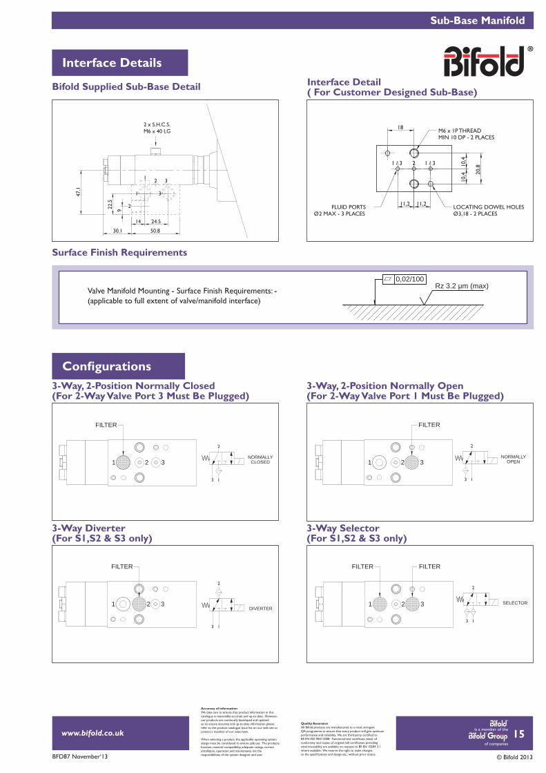
Sub-Base Manifold
Interface Details
15
Accuracy of informationWe take care to ensure that product information in thiscatalogue is reasonably accurate and up-to-date. However,our products are continually developed and updatedso to ensure accurate and up-to-date information pleaserefer to the product catalogue issue list on our web site orcontact a member of our sales team.
When selecting a product, the applicable operating systemdesign must be considered to ensure safe use. The productsfunction, material compatibility, adequate ratings, correctinstallation, operation and maintenance are theresponsibilities of the system designer and user.
Quality AssuranceAll Bifold products are manufactured to a most stringentQA programme to ensure that every product will give optimum
total traceability are available on request, to BS EN 10204 3.1where available. We reserve the right to make changes
Bifold Supplied Sub-Base Detail Interface Detail ( For Customer Designed Sub-Base)
1 2 3
FILTER
FILTER FILTER
321
3
2
1
1 2
2 x S.H.C.S.M6 x 40 LG
3
50.830.1
14 24.5
22.5
9
47.1
M6 x 1P THREADMIN 10 DP - 2 PLACES
FLUID PORTSØ2 MAX - 3 PLACES
LOCATING DOWEL HOLESØ3,18 - 2 PLACES
2 1 / 31 / 3
18
11,2 11,2
20,810
,410
,41 2 3
FILTER
32
FILTER
1
3-Way, 2-Position Normally Closed(For 2-Way Valve Port 3 Must Be Plugged)
3-Way Diverter (For S1,S2 & S3 only)
3-Way Selector(For S1,S2 & S3 only)
3-Way, 2-Position Normally Open(For 2-Way Valve Port 1 Must Be Plugged)
Surface Finish Requirements
NORMALLY OPEN
3 1
2
DIVERTER
3 1
2
SELECTOR
3 1
2
NORMALLY CLOSED
3 1
2
r 0,02/100Rz 3.2 μm (max)
Valve Manifold Mounting - Surface Finish Requirements: - (applicable to full extent of valve/manifold interface)
is a member of the
of companies
www.bifold.co.uk
BFD87 November‘13 © Bifold 2013
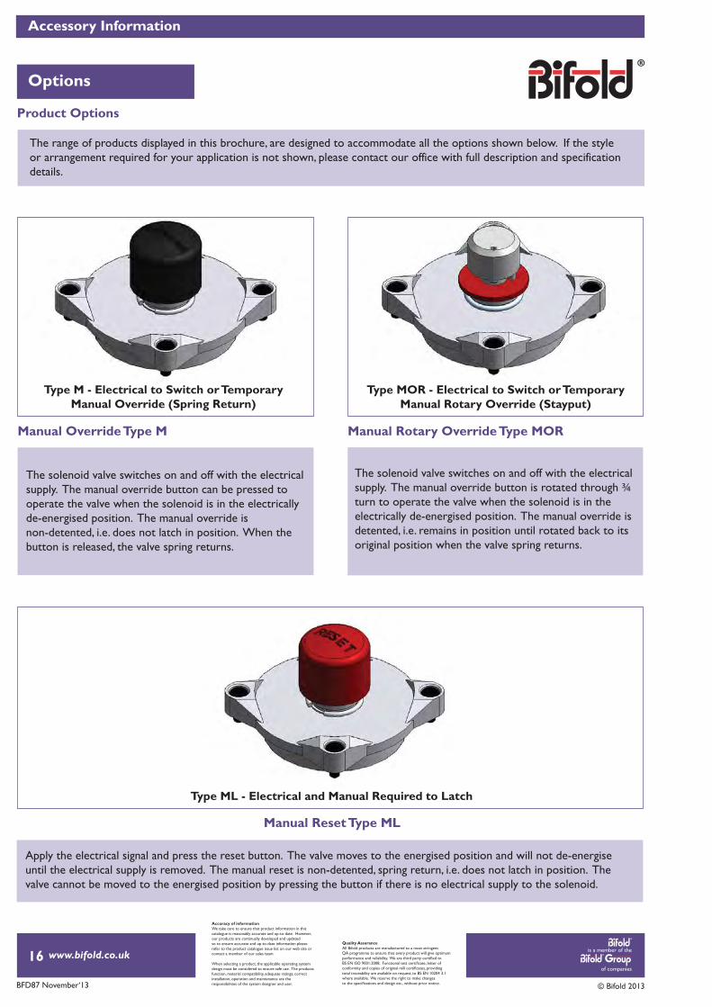
Accessory Information
Options
16
Accuracy of informationWe take care to ensure that product information in thiscatalogue is reasonably accurate and up-to-date. However,our products are continually developed and updatedso to ensure accurate and up-to-date information pleaserefer to the product catalogue issue list on our web site orcontact a member of our sales team.
When selecting a product, the applicable operating systemdesign must be considered to ensure safe use. The productsfunction, material compatibility, adequate ratings, correctinstallation, operation and maintenance are theresponsibilities of the system designer and user.
Quality AssuranceAll Bifold products are manufactured to a most stringentQA programme to ensure that every product will give optimum
total traceability are available on request, to BS EN 10204 3.1where available. We reserve the right to make changes
The range of products displayed in this brochure, are designed to accommodate all the options shown below. If the styleor arrangement required for your application is not shown, please contact our office with full description and specificationdetails.
The solenoid valve switches on and off with the electrical supply. The manual override button can be pressed tooperate the valve when the solenoid is in the electrically de-energised position. The manual override isnon-detented, i.e. does not latch in position. When the button is released, the valve spring returns.
The solenoid valve switches on and off with the electrical supply. The manual override button is rotated through ¾ turn to operate the valve when the solenoid is in theelectrically de-energised position. The manual override isdetented, i.e. remains in position until rotated back to its original position when the valve spring returns.
Apply the electrical signal and press the reset button. The valve moves to the energised position and will not de-energise until the electrical supply is removed. The manual reset is non-detented, spring return, i.e. does not latch in position. The valve cannot be moved to the energised position by pressing the button if there is no electrical supply to the solenoid.
Type M - Electrical to Switch or TemporaryManual Override (Spring Return)
Type MOR - Electrical to Switch or TemporaryManual Rotary Override (Stayput)
Type ML - Electrical and Manual Required to Latch
Product Options
Manual Override Type M Manual Rotary Override Type MOR
Manual Reset Type ML

is a member of the
of companies
www.bifold.co.uk
BFD87 November‘13 © Bifold 2013
Typical Assembly Information
Typical Assemblies
17
VALVE LIMITS
VALVE LIMITS
Accuracy of informationWe take care to ensure that product information in thiscatalogue is reasonably accurate and up-to-date. However,our products are continually developed and updatedso to ensure accurate and up-to-date information pleaserefer to the product catalogue issue list on our web site orcontact a member of our sales team.
When selecting a product, the applicable operating systemdesign must be considered to ensure safe use. The productsfunction, material compatibility, adequate ratings, correctinstallation, operation and maintenance are theresponsibilities of the system designer and user.
Quality AssuranceAll Bifold products are manufactured to a most stringentQA programme to ensure that every product will give optimum
total traceability are available on request, to BS EN 10204 3.1where available. We reserve the right to make changes
VALVE LIMITS
VALVE LIMITS
P2T2
T1P1
P3
S1
S2
S3
B
BAT
P
SOL 'X'
SOL 'Z'
Typical Valve Assembly Showing FP01 Solenoid Valves - Manual Reset
Typical Valve Assembly Showing FP01 Solenoid Valves
Schematic
Schematic
Marshalsea Hydraulics LimitedMarshalsea House, Venture WayPriorswood Industrial EstateTaunton, Somerset, TA2 8DE. UK.Tel: +44 (0) 1823 331081Fax: +44 (0) 1823 323382Email: [email protected]: www.bifold.co.uk
Bifold, Bifold Fluidpower, Bifold Subsea and Marshalsea Hydraulics Ltdare all members of the Bifold Group.Registered No. 1787729 in England.
Middleton, Manchester, M24 ISW.
Bifold Fluidpower Ltd11490 Westheimer,Suite 850,Houston, TX, 77077.Tel: +1 (713) 783 4253Fax: +1 (713) 783 0067Email: [email protected]: www.bifold.co.uk
Bifold Fluidpower LtdGreenside Way,Middleton, Manchester,M24 ISW. UK.Tel: +44 (0) 161 345 4777Fax: +44 (0) 161 345 4780Email: [email protected]: www.bifold.co.uk
Bifold Fluidpower LtdToa Payoh Industrial Park,Lorong 8 #07-1475,Singapore, 3109075.Tel: +65 6735 1323Fax: +65 6735 1367Email: [email protected]: www.bifold.co.uk
Innovative and ReliableValve Solutions
www.bifold.co.uk
Instrument, Process,Directional Control Valves,and Pumps
Accuracy of InformationWe take care to ensure that product information in this catalogue is reasonably accurate and up-to-date. However, our products are continually developed and updated so to ensure accurate and up-to-date information please refer to the product catalogue issue list on our web site or contact a member of our sales team.
Quality AssuranceAll Bifold products are manufactured to a most stringent QA programme. Every care is taken at all stages of manufacture to ensure that every product will give optimum performance and reliability. We are third
design etc., without prior notice.
When selecting a product, the applicable operating system design must be considered to ensure safe use. The products function, material compatibility, adequate ratings, correct installation, operation, and maintenance are the responsibilities of the system designer and user.
BFD87 November‘13 © Bifold 2013