Embed Size (px)
Citation preview
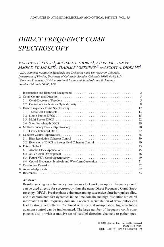
ADVANCES IN ATOMIC, MOLECULAR AND OPTICAL PHYSICS, VOL. 55
DIRECT FREQUENCY COMBSPECTROSCOPY
MATTHEW C. STOWE1, MICHAEL J. THORPE1, AVI PE’ER1, JUN YE1,JASON E. STALNAKER2, VLADISLAV GERGINOV2 and SCOTT A. DIDDAMS2
1JILA, National Institute of Standards and Technology and University of Colorado,Department of Physics, University of Colorado, Boulder, Colorado 80309-0440, USA2Time and Frequency Division, National Institute of Standards and Technology,Boulder, Colorado 80305, USA
1. Introduction and Historical Background . . . . . . . . . . . . . . . . . . . . . . . . . . . . 22. Comb Control and Detection . . . . . . . . . . . . . . . . . . . . . . . . . . . . . . . . . . 5
2.1. Comb Degrees of Freedom . . . . . . . . . . . . . . . . . . . . . . . . . . . . . . . . 52.2. Control of Comb via an Optical Cavity . . . . . . . . . . . . . . . . . . . . . . . . . . 8
3. Direct Frequency Comb Spectroscopy . . . . . . . . . . . . . . . . . . . . . . . . . . . . . 123.1. Theoretical Treatments . . . . . . . . . . . . . . . . . . . . . . . . . . . . . . . . . . . 133.2. Single-Photon DFCS . . . . . . . . . . . . . . . . . . . . . . . . . . . . . . . . . . . . 153.3. Multi-Photon DFCS . . . . . . . . . . . . . . . . . . . . . . . . . . . . . . . . . . . . 223.4. Short Wavelength DFCS . . . . . . . . . . . . . . . . . . . . . . . . . . . . . . . . . . 29
4. Multi-Frequency Parallel Spectroscopy . . . . . . . . . . . . . . . . . . . . . . . . . . . . . 304.1. Cavity Enhanced DFCS . . . . . . . . . . . . . . . . . . . . . . . . . . . . . . . . . . 32
5. Coherent Control Applications . . . . . . . . . . . . . . . . . . . . . . . . . . . . . . . . . 385.1. High Resolution Coherent Control . . . . . . . . . . . . . . . . . . . . . . . . . . . . 395.2. Extension of DFCS to Strong Field Coherent Control . . . . . . . . . . . . . . . . . . 40
6. Future Outlook . . . . . . . . . . . . . . . . . . . . . . . . . . . . . . . . . . . . . . . . . . 456.1. Atomic Clock Applications . . . . . . . . . . . . . . . . . . . . . . . . . . . . . . . . 456.2. XUV Comb Development . . . . . . . . . . . . . . . . . . . . . . . . . . . . . . . . . 466.3. Future VUV Comb Spectroscopy . . . . . . . . . . . . . . . . . . . . . . . . . . . . . 496.4. Optical Frequency Synthesis and Waveform Generation . . . . . . . . . . . . . . . . . 51
7. Concluding Remarks . . . . . . . . . . . . . . . . . . . . . . . . . . . . . . . . . . . . . . . 528. Acknowledgements . . . . . . . . . . . . . . . . . . . . . . . . . . . . . . . . . . . . . . . 529. References . . . . . . . . . . . . . . . . . . . . . . . . . . . . . . . . . . . . . . . . . . . . 53
AbstractBesides serving as a frequency counter or clockwork, an optical frequency combcan be used directly for spectroscopy, thus the name Direct Frequency Comb Spec-troscopy (DFCS). Precise phase coherence among successive ultrashort pulses allowone to explore both fast dynamics in the time domain and high-resolution structuralinformation in the frequency domain. Coherent accumulation of weak pulses canlead to strong field effects. Combined with spectral manipulation, high-resolutionquantum control can be implemented. The large number of frequency comb com-ponents also provide a massive set of parallel detection channels to gather spec-
© 2008 Elsevier Inc. All rights reservedISSN 1049-250X
DOI: 10.1016/S1049-250X(07)55001-9
1

2 M.C. Stowe et al. [1
troscopic information. In this chapter we provide a detailed review of some of thecurrent applications that exploit these unique features, and discuss several futuredirections of DFCS.
1. Introduction and Historical Background
At the end of the 1990s the mode-locked femtosecond laser and its associatedoptical frequency comb made an unanticipated entry into the field of precisionoptical frequency metrology (Udem et al., 1999a, 1999b; Diddams et al., 2000;Jones et al., 2000). It is difficult to overstate the impact of this new technol-ogy on frequency metrology research (Hall, 2006; Hänsch, 2006). In simpleterms, the femtosecond laser frequency comb transformed optical frequency stan-dards into optical clocks by providing a straightforward means to count opti-cal cycles (Diddams et al., 2001; Ye et al., 2001). Just as important, a stabi-lized frequency comb permits the easy comparison of optical standards sep-arated by hundreds of terahertz (Diddams et al., 2001; Stenger et al., 2002),offers new tools for frequency transfer (Holman et al., 2004; Foreman et al.,2007), introduces new approaches to length metrology (Ye, 2004; Minoshimaand Matsumoto, 2000), and provides the carrier–envelope control required forphase-sensitive nonlinear optics and attosecond physics (Paulus et al., 2001;Baltuska et al., 2003).
Beyond its enabling advances in optical frequency metrology, a stabilized opti-cal frequency comb can also be a versatile spectroscopic tool, providing excellentaccuracy, high spectral purity, and at the same time broad spectral coverage. Infact, the concept of using the frequency comb from a mode-locked laser for highresolution spectroscopy precedes the more recent comb-related excitement byseveral decades. The 1970s saw the emergence of the theory and experiments con-taining the roots of the ideas that will be discussed in detail in this review. Whilethe pulses were longer (nano- or picosecond compared with femtosecond) and thefrequency control was rudimentary by today’s standards, many of the early exper-iments already highlighted the advantages of a mode-locked laser frequency combfor multi-photon spectroscopy and measuring optical frequency differences.
Considering our present-day understanding of the frequency comb, it is notsurprising that these early experiments emerged as either time- or frequency-domain interpretations of the interaction of a series of coherent pulses withan atomic system. From the time-domain perspective, two early experimentswere cast as variations of Ramsey spectroscopy applied to two-photon transi-tions (Salour and Cohen-Tannoudji, 1977; Teets et al., 1977). In both cases,linewidths less than the pulse bandwidth were observed due to the coherence
1] DIRECT FREQUENCY COMB SPECTROSCOPY 3
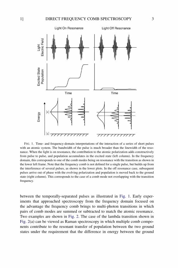
FIG. 1. Time- and frequency-domain interpretations of the interaction of a series of short pulseswith an atomic system. The bandwidth of the pulse is much broader than the linewidth of the reso-nance. When the light is on resonance, the contribution to the atomic polarization adds constructivelyfrom pulse to pulse, and population accumulates in the excited state (left column). In the frequencydomain, this corresponds to one of the comb modes being on resonance with the transition as shown inthe lower left frame. Note that the frequency comb is not defined for a single pulse, but builds up fromthe interference of several pulses, as shown in the lower plots. In the off resonance case, subsequentpulses arrive out of phase with the evolving polarization and population is moved back to the groundstate (right column). This corresponds to the case of a comb mode not overlapping with the transitionfrequency.
between the temporally-separated pulses as illustrated in Fig. 1. Early exper-iments that approached spectroscopy from the frequency domain focused onthe advantage the frequency comb brings to multi-photon transitions in whichpairs of comb modes are summed or subtracted to match the atomic resonance.Two examples are shown in Fig. 2. The case of the lambda transition shown inFig. 2(a) can be viewed as Raman spectroscopy in which multiple comb compo-nents contribute to the resonant transfer of population between the two groundstates under the requirement that the difference in energy between the ground
4 M.C. Stowe et al. [1
© 1981 American Physical Society
© 1996 Elsevier
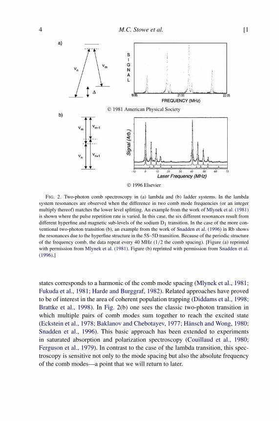
FIG. 2. Two-photon comb spectroscopy in (a) lambda and (b) ladder systems. In the lambdasystem resonances are observed when the difference in two comb mode frequencies (or an integermultiply thereof) matches the lower level splitting. An example from the work of Mlynek et al. (1981)is shown where the pulse repetition rate is varied. In this case, the six different resonances result fromdifferent hyperfine and magnetic sub-levels of the sodium D1 transition. In the case of the more con-ventional two-photon transition (b), an example from the work of Snadden et al. (1996) in Rb showsthe resonances due to the hyperfine structure in the 5S–5D transition. Because of the periodic structureof the frequency comb, the data repeat every 40 MHz (1/2 the comb spacing). [Figure (a) reprintedwith permission from Mlynek et al. (1981). Figure (b) reprinted with permission from Snadden et al.(1996).]
states corresponds to a harmonic of the comb mode spacing (Mlynek et al., 1981;Fukuda et al., 1981; Harde and Burggraf, 1982). Related approaches have provedto be of interest in the area of coherent population trapping (Diddams et al., 1998;Brattke et al., 1998). In Fig. 2(b) one sees the classic two-photon transition inwhich multiple pairs of comb modes sum together to reach the excited state(Eckstein et al., 1978; Baklanov and Chebotayev, 1977; Hänsch and Wong, 1980;Snadden et al., 1996). This basic approach has been extended to experimentsin saturated absorption and polarization spectroscopy (Couillaud et al., 1980;Ferguson et al., 1979). In contrast to the case of the lambda transition, this spec-troscopy is sensitive not only to the mode spacing but also the absolute frequencyof the comb modes—a point that we will return to later.

2] DIRECT FREQUENCY COMB SPECTROSCOPY 5
2. Comb Control and Detection
In this section we provide a brief review of optical frequency comb structure andthe means for its stabilization. More detailed reviews can be found in Cundiffet al. (2001), Cundiff and Ye (2003), Ye et al. (2003), Ye and Cundiff (2005).Passive optical cavities will also be discussed here, which will serve three roles:frequency comb stabilization; buildup of intracavity field strength; and enhance-ment of spectroscopic detection sensitivity.
2.1. COMB DEGREES OF FREEDOM
The frequency spectrum of an ideal mode-locked laser is generally composed ofhundreds of thousands of equidistant modes spaced by the repetition rate of thelaser, thus the name optical frequency comb. In practice, however, a mode-lockedlaser exhibits noise on the optical phase and repetition rate of the emitted pulses.In this section we briefly review the relevant degrees of freedom governing thelaser frequency spectrum and the common methods of stabilization.
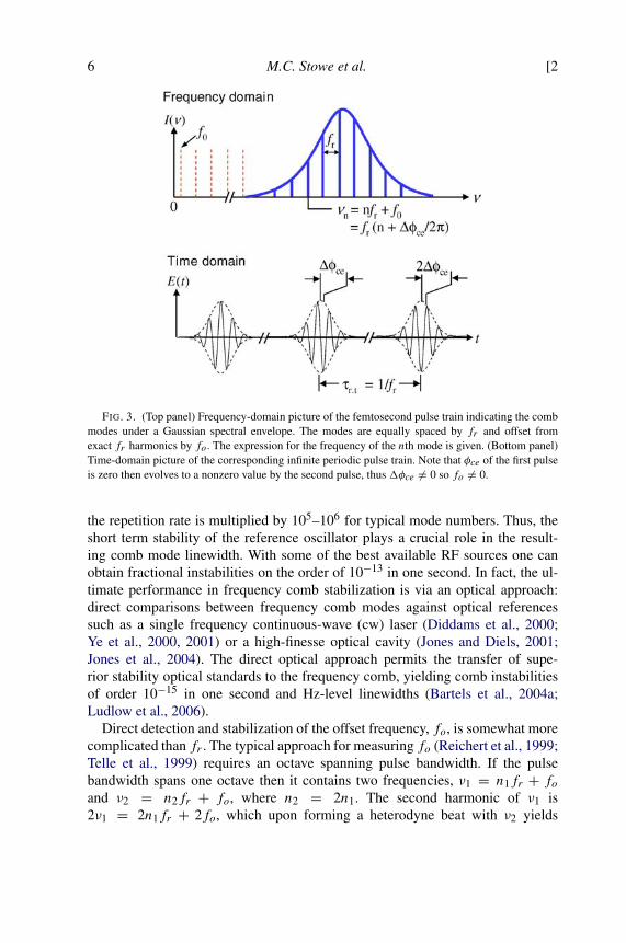
There are only two degrees of freedom necessary to uniquely specify the fre-quency of every comb mode (Reichert et al., 1999). The first is the repetitionrate of the laser, fr , defined as the inverse of the inter-pulse period. As can beseen in Fig. 3 the comb mode spacing is exactly fr . Secondly, the rate changeof optical phase from pulse to pulse must be specified. Referring to Fig. 3 thecarrier–envelope offset phase, φce, is defined as the relative phase between thepeak of the pulse envelope and the underlying electric field. In general the φce
changes between pulses, it is this change, �φce, which determines the offset fre-quency, fo, of the comb modes as shown in Fig. 3. Using these definitions thefrequency of the mode indexed by n is given by νn = nfr+fo, with fo = fr
�φce2π .
For a laser with a repetition rate between 1 to 100 MHz and center wavelengthof 800 nm the mode index n is of order 105 to 106. In general, fr and fo can beindependently measured and then controlled via two servo transducers acting onthe cavity length and the dispersion of the mode-locked laser.
The laser repetition rate fr is generally directly measured on a fast, multi-GHzbandwidth, photodiode. This produces a series of radio frequency (RF) beats atmultiples of fr which can be used for phase locking to an RF reference such as acrystal oscillator with low short-term noise. To achieve superior phase sensitivity,one of the high harmonics of fr is used for the phase lock, for example the tenthharmonic of a 100 MHz repetition rate laser can be locked to a 1 GHz referenceoscillator. The beat phase between the measured fr harmonic and the referenceis filtered and amplified for use as an error signal to servo the laser cavity lengthvia a piezo-electric transducer (PZT) mounted output coupler. Because an opti-cal frequency is related to the repetition rate by the mode number, any noise on
6 M.C. Stowe et al. [2
FIG. 3. (Top panel) Frequency-domain picture of the femtosecond pulse train indicating the combmodes under a Gaussian spectral envelope. The modes are equally spaced by fr and offset fromexact fr harmonics by fo. The expression for the frequency of the nth mode is given. (Bottom panel)Time-domain picture of the corresponding infinite periodic pulse train. Note that φce of the first pulseis zero then evolves to a nonzero value by the second pulse, thus �φce �= 0 so fo �= 0.
the repetition rate is multiplied by 105–106 for typical mode numbers. Thus, theshort term stability of the reference oscillator plays a crucial role in the result-ing comb mode linewidth. With some of the best available RF sources one canobtain fractional instabilities on the order of 10−13 in one second. In fact, the ul-timate performance in frequency comb stabilization is via an optical approach:direct comparisons between frequency comb modes against optical referencessuch as a single frequency continuous-wave (cw) laser (Diddams et al., 2000;Ye et al., 2000, 2001) or a high-finesse optical cavity (Jones and Diels, 2001;Jones et al., 2004). The direct optical approach permits the transfer of supe-rior stability optical standards to the frequency comb, yielding comb instabilitiesof order 10−15 in one second and Hz-level linewidths (Bartels et al., 2004a;Ludlow et al., 2006).
Direct detection and stabilization of the offset frequency, fo, is somewhat morecomplicated than fr . The typical approach for measuring fo (Reichert et al., 1999;Telle et al., 1999) requires an octave spanning pulse bandwidth. If the pulsebandwidth spans one octave then it contains two frequencies, ν1 = n1fr + foand ν2 = n2fr + fo, where n2 = 2n1. The second harmonic of ν1 is2ν1 = 2n1fr + 2fo, which upon forming a heterodyne beat with ν2 yields
2] DIRECT FREQUENCY COMB SPECTROSCOPY 7
a beat note at the desired fo frequency. This technique is referred to as self-referencing because it forms the beat note entirely from the laser output with-out any separate reference frequencies. It is now also possible to obtain anoctave bandwidth directly from a suitably constructed Ti:sapphire laser (Ell etal., 2001; Fortier et al., 2006a, 2003; Mücke et al., 2005). A common tech-nique for generating the required bandwidth is via four-wave mixing in anextra-cavity highly nonlinear fiber. Other techniques for measuring fo requireless than an octave of bandwidth. For example, one needs only 2/3 of an oc-tave bandwidth by using a heterodyne beat between two sets of adjacent modes,one formed by doubling the high-frequency portion of the original comb spec-trum and the other from tripling the low-frequency portion (Telle et al., 1999;Ramond et al., 2002).
It was the development of dispersion modified micro-structured fiber (Ranka etal., 2000; Dudley et al., 2006) that enabled the first experimental demonstrationof self-referencing (Jones et al., 2000; Apolonski et al., 2000). Micro-structurefiber, also called photonic crystal fiber, exhibits two important features for effi-ciently producing an octave spanning bandwidth. Micro-structure fiber gets itsname from the regular pattern of air holes that extend the length of the fiber andsurrounding the core, forming a photonic band gap to confine the light. By tuningthe waveguide dispersion of the fiber the net dispersion can be made zero nearthe desired input pulse wavelength. Typically such a fiber has a core diameter ofabout 1.7 µm for a zero dispersion point at 800 nm. Confining the pulse to sucha small area can generate extremely large peak intensities, which due to the zerodispersion property may persist through the fiber with minimal pulse stretching.This combination of high intensity over a long interaction length allows for ef-ficient four-wave mixing. In practice transform limited pulses with energies oforder nanojoules can be used with approximately 10 cm of fiber to generate thenecessary octave bandwidth.
To understand how to servo the laser and thus control fo we must first under-stand the origin of the phase, φce. Recall that φce is defined between the pulseenvelope, which travels at the group velocity vg , and the underlying electric field,which travels at the phase velocity vp. In the laser cavity the difference of vg andvp results in a generally nonzero �φce given by
�φce = lcωc
(1
vg− 1
vp
),
where lc is the cavity round trip length and ωc is the carrier frequency. Withthis knowledge in mind it is clear that tuning the dispersion of the cavitywill also change fo. This was first accomplished by tilting the end mirror ofa linear cavity in which the spectrum is spatially dispersed via the intracav-ity prisms, the resulting wavelength-dependent extra path length changes thegroup velocity. Experimentally this can be done by mounting the end mirror
8 M.C. Stowe et al. [2
after the intracavity prism pair on a split PZT that is driven such that the mir-ror tilts in response to the error signal (Reichert et al., 1999; Cundiff et al.,2001). Alternatively, one can change the dispersion of the laser cavity via con-trol of the pump power (Holman et al., 2003a). This approach can achieve atypical servo bandwidth of the order of 100 kHz. Once fo is stabilized, frcan be controlled using an error signal generated from a heterodyne beat be-tween a cw optical frequency standard and one of the neighboring comb modes.This stabilization scheme comprises the basic gearwork for an optical atomicclock.
2.2. CONTROL OF COMB VIA AN OPTICAL CAVITY
A passive, high-finesse, and low-dispersion optical cavity is useful in many as-pects to aid in high precision DFCS, as will be discussed in the following sections.A broad bandwidth optical frequency comb can be efficiently coupled into such acavity, enabling its use as a frequency reference as well as enhancement of powerand interaction length. Indeed, understanding the intricate interactions between atrain of ultrashort pulses and passive optical cavities, along with the developmentof the capability to efficiently couple and coherently store ultrashort pulses of lightinside a high-finesse optical cavity, has been an area of focused research (Jonesand Ye, 2002). Several important studies have ensued. Intracavity storage and am-plification of ultrashort pulses in the femtosecond regime require precise controlof the reflected spectral phase of the resonator mirrors as well as the optical lossof the resonator. While the reflected phase and group delay of the mirrors onlychange the effective length of the resonator, the group delay dispersion (GDD)and higher-order derivatives of the group delay with respect to wavelength af-fect the pulse shape. The net cavity GDD over the bandwidth of the pulse needsto be minimized in order to maintain the shape of the resonant pulse and allowfor the coherent addition of energy from subsequent pulses (Thorpe et al., 2005;Schliesser et al., 2006).
Direct stabilization of a frequency comb to a high-finesse optical cavity ben-efits from a low cavity dispersion that leads to a large spectral range overwhich comb and cavity modes can overlap precisely (Jones and Diels, 2001;Jones et al., 2004). A simplified schematic for cavity stabilization of femtosecondpulses is shown in Fig. 4. The pulse train is mode-matched to the passive high-finesse cavity after passing through an electro–optical phase modulator (EOM).Both fr and fo need proper adjustments to optimize frequency overlap betweenthe comb components and the corresponding cavity modes. The light reflectedfrom the cavity is spectrally dispersed with a grating and error signals from thecavity are obtained at different spectral regions resonant with the cavity (ωi) us-ing the standard Pound–Drever–Hall RF sideband technique (Drever et al., 1983).
2] DIRECT FREQUENCY COMB SPECTROSCOPY 9
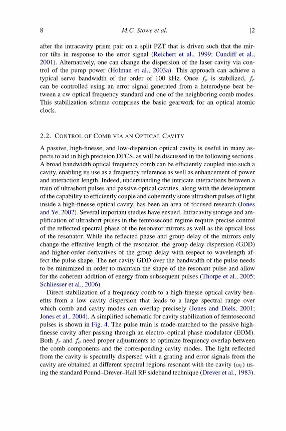
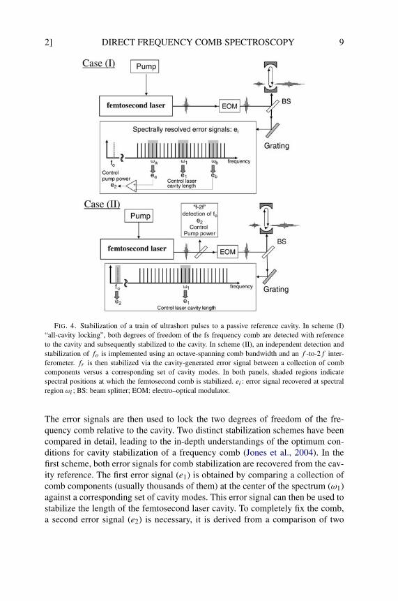
FIG. 4. Stabilization of a train of ultrashort pulses to a passive reference cavity. In scheme (I)“all-cavity locking”, both degrees of freedom of the fs frequency comb are detected with referenceto the cavity and subsequently stabilized to the cavity. In scheme (II), an independent detection andstabilization of fo is implemented using an octave-spanning comb bandwidth and an f -to-2f inter-ferometer. fr is then stabilized via the cavity-generated error signal between a collection of combcomponents versus a corresponding set of cavity modes. In both panels, shaded regions indicatespectral positions at which the femtosecond comb is stabilized. ei : error signal recovered at spectralregion ωi ; BS: beam splitter; EOM: electro–optical modulator.
The error signals are then used to lock the two degrees of freedom of the fre-quency comb relative to the cavity. Two distinct stabilization schemes have beencompared in detail, leading to the in-depth understandings of the optimum con-ditions for cavity stabilization of a frequency comb (Jones et al., 2004). In thefirst scheme, both error signals for comb stabilization are recovered from the cav-ity reference. The first error signal (e1) is obtained by comparing a collection ofcomb components (usually thousands of them) at the center of the spectrum (ω1)against a corresponding set of cavity modes. This error signal can then be used tostabilize the length of the femtosecond laser cavity. To completely fix the comb,a second error signal (e2) is necessary, it is derived from a comparison of two
10 M.C. Stowe et al. [2
errors obtained at two spectral regions located symmetrically around the center,as shown in Fig. 4. The second error signal is used to control the laser cavitydispersion. In scheme (II), the second error signal is derived from a standard f -to-2f self-referencing spectrometer, which corresponds to a direct detection andstabilization of fo. The value of fo is chosen to allow the maximum number offrequency comb modes to be matched to the cavity.
The stability of the frequency comb can be determined in both the optical andthe radio frequency domains. It has been verified that the second scheme per-formed better than the first one due to the effective long “lever arm” (Jones etal., 2004). In principle, one could improve the performance of the first schemeby using a larger spectral separation between ωa and ωb. However, the abilityto simultaneously optimize error signals in different spectral regions is neces-sarily limited by the parabolic variation of the cavity free-spectral-range (FSR)frequency, characteristic of the simple quarter-wave stack dielectric mirrors em-ployed. By employing lower dispersion mirrors, the performance of the firstscheme approaches that of the second. Using an independent, stable cw laser asa reference, measurement of the linewidth and stability of the cavity-stabilizedoptical frequency comb reveal superior performance comparable to that achievedby cavity-stabilized cw lasers.
The resulting frequency/phase stability between the frequency comb and thecavity modes demonstrates a fully coherent process of intracavity pulse buildupand storage. Similar to the state-of-art stabilization of cw lasers, a cavity-stabilized ultrafast laser demonstrates superior short-term stability of both frand fo. The improved stability is beneficial for frequency-domain applications,where the relative phase or “chirp” between comb components is unimpor-tant (e.g. optical frequency metrology), as well as time-domain applicationswhere the pulse shape and/or duration is vital, such as in nonlinear optical in-teractions. These applications include optical frequency measurement, carrier–envelope phase stabilization, all-optical atomic clocks, optical frequency synthe-sizer, and coherent pulse synthesis.
To further improve the quality of femtosecond enhancement cavities, a fem-tosecond comb-based measurement protocol has been developed to preciselycharacterize mirror loss and dispersion (Thorpe et al., 2005; Schliesser et al.,2006). This technical capability has facilitated production of large bandwidth,low-loss and low-dispersion mirrors. In addition, nonlinear responses of intracav-ity optical elements have been studied, demonstrating their limitation on powerscalability (Moll et al., 2005). This study has led to the design of novel cav-ity geometries to overcome this limitation (Moll et al., 2006). In short, nearlythree-orders of power enhancement inside a femtosecond buildup cavity within aspectral bandwidth of 30 nm has been achieved, resulting in an intracavity pulsetrain that (1) is completely phase coherent to the original comb from the oscil-lator, (2) has the original laser’s repetition rate (100 MHz), (3) has a pulse peak
2] DIRECT FREQUENCY COMB SPECTROSCOPY 11
energy exceeding 5 µJ (average power > 500 W), intracavity peak intensity ap-proaching 1014 W/cm2, and (4) is under 60 fs pulse duration. We also note thatthis enhancement cavity approach is compatible with a number of femtosecondlaser systems, including mode-locked Ti:sapphire and fiber lasers.
The use of power-enhanced intracavity pulses for high harmonic generationwill be discussed in Section 6.2. This is partly motivated by the fact that co-herent optical spectroscopy has now led to the recovery of a record-high qual-ity factor (Q > 2.4 × 10¹⁴) for a doubly “forbidden” natural resonance ob-served in a large ensemble of ultracold Sr atoms trapped in an optical lattice(Boyd et al., 2006). This unprecedented spectral resolving power impacts fieldsranging from precision frequency metrology to quantum optics and quantuminformation science. Ultrastable lasers, together with optical frequency combs,can now maintain optical phase coherence beyond 1 s and transfer this stabil-ity across hundreds of terahertz (Bartels et al., 2004a; Ludlow et al., 2006).As it becomes increasingly challenging to maintain phase coherence beyondmultiple seconds, it is natural to look beyond the visible domain and considerspeeding up the “wheel of precision measurement” to higher carrier frequen-cies. Two related experimental directions are currently being pursued to addressthis vision. One is the generation of phase coherent, high repetition-rate fre-quency combs in the VUV (50–200 nm) spectral domain (Jones et al., 2005;Gohle et al., 2005). In parallel, direct frequency comb spectroscopy (Marian etal., 2004) is being explored to ready ourselves for quantum optics and precisionspectroscopy once phase coherent sources (necessarily in the form of a train ofpulses) become available in VUV. In addition to the power enhancement aspect,a femtosecond cavity effectively increases the interaction length between matterand light, allowing direct frequency comb spectroscopy to measure weak linear ornonlinear atomic and molecular absorption with dramatically increased sensitivityand across a vast spectral bandwidth (Thorpe et al., 2006, 2007).
The coherently enhanced pulse train stored in the cavity can also be switchedout using a cavity-dumping element (Bragg cell), resulting in phase-coherent, am-plified pulses at a reduced repetition frequency (Potma et al., 2003; Vidne et al.,2003; Jones and Ye, 2004). The net cavity group delay dispersion over the band-width of the pulse is minimized to maintain the shape of the resonant pulse. Thiscoherent pulse-stacking technique has been applied to both picosecond (Potmaet al., 2003) and femtosecond pulses (Jones and Ye, 2004), demonstrating ampli-fications >500. An important application of these advanced pulse-control tech-nologies is in the field of nonlinear optical spectroscopy and nanoscale imaging.Using two tightly synchronized picosecond lasers, one can achieve a significantimprovement in experimental sensitivity and spatial resolutions for vibrationalimaging based on coherent anti-Stokes Raman spectroscopy (CARS) for acqui-sition of chemically selective maps of biological samples (Potma et al., 2002,

12 M.C. Stowe et al. [3
2004). The technologies of pulse synchronization and coherent pulse stacking fitwell with this task of combining spectroscopy and microscopy.
3. Direct Frequency Comb Spectroscopy
Femtosecond lasers have been used to reveal ultrafast dynamics and providewide bandwidth spectroscopic information in atomic, molecular, and condensedmatter systems (Zewail, 2000; Jonas, 2003). The advent of precision femtosec-ond optical combs brings a new set of tools for precision atomic and molecularspectroscopy. For example, ultrafast lasers are now being used not only for time-resolved spectroscopy on fast dynamics, but also for precision spectroscopy ofelectronic transitions. Indeed, coherent control of dynamics and precision mea-surement are merging into a joint venture (Stowe et al., 2006). The ability topreserve optical phase coherence and superior spectral resolution over a widespectral bandwidth permits detailed and quantitative studies of atomic and molec-ular structure and dynamics. The spectral analysis can be performed over a broadwavelength range, allowing precise investigations of minute changes in atomicand molecular structure over a large dynamic range (Chen and Ye, 2003). Forexample, absolute frequency measurement of vibration-overtone transitions andother related resonances (such as hyperfine splitting) can reveal precise informa-tion about the molecular potential-energy surface and relevant perturbation effects(Chen et al., 2004, 2005).
With precise control of both time- and frequency-domain properties of a pulsetrain, these two features can be combined into a single spectroscopic study, asdemonstrated in the following sections. The broad frequency comb bandwidthavailable for modern comb spectroscopy measurements distinguishes them fromthe earlier picosecond-pulse based experiments, leading to truly united time–frequency spectroscopy for broad-bandwidth spectroscopy (Marian et al., 2004).Precision spectroscopy of global atomic structure is achieved with a direct useof a single, phase-stabilized femtosecond optical comb. The pulsed nature of ex-citation allows real-time monitoring and control capabilities for both optical andquantum coherent interactions and state transfer. It is a synthesis of the fields ofprecision spectroscopy and coherent control: at short time scales the coherent ac-cumulation and population transfer is monitored, at long times all the informationpertinent to the atomic level structure is measured at a resolution limited onlyby the natural atomic linewidth, with a spectral coverage spanning hundreds ofterahertz. This powerful combination of frequency-domain precision and time-domain dynamics represents a new paradigm for spectroscopy.
The precision and control of both the frequency and time domain achievablewith femtosecond frequency combs introduce many new features to spectroscopy.In particular the spectroscopic resolution and precision are not compromised by
3] DIRECT FREQUENCY COMB SPECTROSCOPY 13
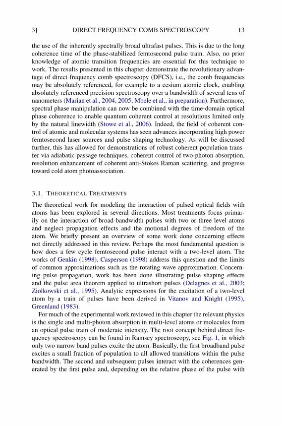
the use of the inherently spectrally broad ultrafast pulses. This is due to the longcoherence time of the phase-stabilized femtosecond pulse train. Also, no priorknowledge of atomic transition frequencies are essential for this technique towork. The results presented in this chapter demonstrate the revolutionary advan-tage of direct frequency comb spectroscopy (DFCS), i.e., the comb frequenciesmay be absolutely referenced, for example to a cesium atomic clock, enablingabsolutely referenced precision spectroscopy over a bandwidth of several tens ofnanometers (Marian et al., 2004, 2005; Mbele et al., in preparation). Furthermore,spectral phase manipulation can now be combined with the time-domain opticalphase coherence to enable quantum coherent control at resolutions limited onlyby the natural linewidth (Stowe et al., 2006). Indeed, the field of coherent con-trol of atomic and molecular systems has seen advances incorporating high powerfemtosecond laser sources and pulse shaping technology. As will be discussedfurther, this has allowed for demonstrations of robust coherent population trans-fer via adiabatic passage techniques, coherent control of two-photon absorption,resolution enhancement of coherent anti-Stokes Raman scattering, and progresstoward cold atom photoassociation.
3.1. THEORETICAL TREATMENTS
The theoretical work for modeling the interaction of pulsed optical fields withatoms has been explored in several directions. Most treatments focus primar-ily on the interaction of broad-bandwidth pulses with two or three level atomsand neglect propagation effects and the motional degrees of freedom of theatom. We briefly present an overview of some work done concerning effectsnot directly addressed in this review. Perhaps the most fundamental question ishow does a few cycle femtosecond pulse interact with a two-level atom. Theworks of Genkin (1998), Casperson (1998) address this question and the limitsof common approximations such as the rotating wave approximation. Concern-ing pulse propagation, work has been done illustrating pulse shaping effectsand the pulse area theorem applied to ultrashort pulses (Delagnes et al., 2003;Ziolkowski et al., 1995). Analytic expressions for the excitation of a two-levelatom by a train of pulses have been derived in Vitanov and Knight (1995),Greenland (1983).
For much of the experimental work reviewed in this chapter the relevant physicsis the single and multi-photon absorption in multi-level atoms or molecules froman optical pulse train of moderate intensity. The root concept behind direct fre-quency spectroscopy can be found in Ramsey spectroscopy, see Fig. 1, in whichonly two narrow band pulses excite the atom. Basically, the first broadband pulseexcites a small fraction of population to all allowed transitions within the pulsebandwidth. The second and subsequent pulses interact with the coherences gen-erated by the first pulse and, depending on the relative phase of the pulse with
14 M.C. Stowe et al. [3
the coherence, population is either excited or de-excited. We refer to the coherentinteraction of a series of pulses with an atomic or molecular transition as coherentaccumulation. This is the key physical concept behind the signal size and resolu-tion enabled by DFCS. To excite only one of many states in the bandwidth of thepulse, fo and fr may be chosen to always be in phase with only one coherence.In the frequency-domain picture this is simply to say one comb mode is resonantand all others are detuned. To properly treat multi-photon absorption the sum ofcomb modes must be considered, for example in a two-photon transition theremay be hundreds of thousands of resonant mode pairs. Due to the fact that morethan one pair of modes may excite a two-photon transition the spectral phase ofeach mode, and intermediate state detunings, must be considered to account forquantum interference effects.
Two models are used for the majority of the theoretical predictions for the ex-periments presented in Sections 3.2 and 3.3. The first is a perturbative modelsuitable for two-photon absorption of transform limited pulses in multi-levelatoms, for example the many hyperfine levels of the 5S, 5P, and 5D states of ru-bidium 87. This technique, presented by Felinto et al. (2004), uses the impulsiveexcitation approximation such that the spectral content and phase of the pulse arenot included. It provides a computationally fast method to predict the complicatedoptical pumping effects present between the many comb modes and electronicstates. Other experiments require either a non-perturbative treatment or the capa-bility of modeling spectral phase effects for multi-photon absorption. In this caseone can directly numerically solve the Louiville equation for the density matrixof the system for a three-level model under arbitrary shaped pulse excitation. Theadvantage of this approach is that it correctly predicts pulse shaping effects onmulti-photon transitions and the non-perturbative effect of power broadening ofatomic transitions relevant to correctly modeling parts of Sections 3.3 and 5.
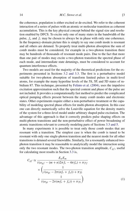
In many experiments it is possible to treat only those comb modes that areresonant with a transition. The simplest case is when the comb is tuned to beresonant with only one single-photon transition and the nearest mode for all othertransitions is detuned several linewidths. Similarly, for a resonantly enhanced two-photon transition it may be reasonable to analytically model the interaction usingonly the two resonant modes. The two-photon transition amplitude, Cgf , usefulfor calculating most results in Section 3.3 is,
Cgf ∝ EnEm
i(ωgf − (m+ n)2πfr − 4πfo)+ πγf×
(1
i(ωgi − 2π(nfr + fo))+ πγi(1)+ 1
i(ωgi − 2π(mfr + fo))+ πγi)
3] DIRECT FREQUENCY COMB SPECTROSCOPY 15
where En,m are the electric fields of the nth and mth modes of the comb, γi(f )is the intermediate (final) state scattering rate, ωgi(gf ) is ground to intermediate(final) state transition frequency. In general, the total transition amplitude is thesum over all modes of the comb and intermediate states. The full equation withcomparison to time-domain techniques may be found in Yoon et al. (2000).
In molecular systems, where the number of individual states covered by thebandwidth of the pulses may be too large to handle by direct solution in statespace, one can use techniques developed for the modeling of wave-packet dynam-ics, such as the split-operator method. In these techniques, one directly solves thetime-dependent Schrödinger equation with a set of electronic potentials coupledby the time-dependent fields of the pulses, see Garraway and Suominen (1995)for a comprehensive review. The theoretical results shown in Section 5.2 wereobtained with such a model. Like in the case of atomic excitation, the coherentaccumulation was modeled by simulating a single femtosecond pulse interactionfollowed by free evolution of the molecular coherences between pulses, this pro-cedure is then repeated for every pulse.
3.2. SINGLE-PHOTON DFCS
Of the many applications directly using the output of a femtosecond laser fre-quency comb (FLFC) for spectroscopy, single-photon spectroscopy is the easiestto realize experimentally. A single frequency component of the broad comb spec-trum is used to selectively excite an atomic or molecular transition. The spectra arerecorded by measuring the excited-state fluorescence while changing the laser’srepetition rate fr or carrier–envelope offset frequency fo. The time-domain prop-erties of the laser determine only the frequency and width of the selected compo-nent, but the requirements for pulse overlapping or preserving the phase relationacross multiple comb components are relaxed. The femtosecond laser frequencycomb can be viewed simply as a multimode laser with narrow-linewidth modes atknown optical frequencies. As a result, all methods of cw laser spectroscopy canbe applied with the advantage of absolute frequency calibration determined bythe knowledge of fr and fo. Additionally, the combs have spectral componentswhere no tunable cw laser sources exist, and they cover a broad spectral intervalallowing spectroscopy of different atomic or molecular systems to be done withthe same laser system. In particular the high peak intensity attainable with fem-tosecond pulses allows for efficient nonlinear conversion to spectral regions withdifficult or no accessibility by traditional cw laser techniques, see Section 3.4 fora specific example.
Several disadvantages of using FLFC for single-photon spectroscopy have to bementioned. The total laser intensity is distributed among ∼105 comb modes, re-sulting in a per mode intensity typically below 1 µW. Consequently spectroscopy
16 M.C. Stowe et al. [3
must be performed with very low laser power levels. This limits the sub-Dopplerspectroscopy experiments to atomic beams or laser cooled systems, where theDoppler width has already been reduced geometrically or using laser cooling(Gerginov et al., 2005; Marian et al., 2004). Saturated absorption is possible, butin order to reach significant saturation, tight laser beam focusing is required whichleads to time of flight broadening and other systematic effects. A possible solu-tion to the low intensity problem is amplification of the comb’s output, as shownin Section 3.2.3.
When the repetition rate is swept in order to measure the atomic transitionspectrum, the same difficulties as when using multimode lasers are encountered.Due to interleaving, all spectral features will be present in a frequency windowdetermined by the separation of the comb components at the optical frequency ofinterest. The identification of the spectral lines becomes problematic. The pres-ence of many other comb components, even if filtered by an interference filter orusing techniques described in the sections below, leads to systematic effects suchas AC Stark shifts. It is difficult to directly measure the intensity of any singlecomb mode, although it may be inferred from the laser’s spectral shape, power,and mode separation. The method of measuring the excited population in the fol-lowing experiments is either directly via fluorescence or population transfer with acw probe laser. This is preferable because in transmission, all components presentin the comb spectrum contribute to the background.
Determining the absolute frequency of a transition measured by DFCS re-quires the determination of the resonant comb mode index, n. There are generallytwo ways to determine the index. In some applications the frequency may bealready known to within half the comb mode spacing. If this is the case thenit is trivial to unambiguously determine n and calculate the absolute transitionfrequency using νn = nfr + fo. The second more general technique is to mea-sure the linecenter with two or more different fr . In principle, that is in theabsence of uncertainty corresponding to the fo and fr of the measured linecen-ter, the idea is straightforward. Measure the linecenter with νn = nfr + fo andνn = n(fr+�fr)+(fo+�fo), where�fr is small enough such that the resonantmode remains the same. From these measurements it is clear n = −�fo/�fr . Inpractice there is measurement uncertainty and�fr must be made larger, in generalthe resonant comb mode will change but �n may be determined. Cases may alsoarise in which two different atomic transitions are spaced by approximately fr ,these lines would overlap and it may be necessary to choose an appropriate frrange, or filter the pulse spectrum, to reduce the congestion of resonant transi-tions.
3.2.1. Single-Photon Spectroscopy of Rubidium
The first DFCS experiment we discuss measured the 5S to 5P single-photon tran-sitions in laser cooled 87Rb atoms (Marian et al., 2005). This simple application

3] DIRECT FREQUENCY COMB SPECTROSCOPY 17
FIG. 5. Relevant energy levels studied in experiments in (a) Rb and (b) Cs. The two-photon tran-sitions reached by two modes of the comb are discussed in Section 3.3. Although not shown the combresolution allows the excitation of specific hyperfine levels.
is a clear demonstration of how DFCS can be used to determine the absolutefrequency of any allowed transition within the laser bandwidth, see Fig. 5(a).A mode-locked Ti:sapphire laser operated at 100 MHz repetition rate, outputting20 fs pulses, with a center wavelength of 780 nm was used to excite a sampleof 87Rb atoms in a magneto–optical trap (MOT). A crystal oscillator with lowshort-term instability was used to lock fr resulting in a comb mode linewidth of330 kHz at 1 ms integration time. To absolutely reference the frequencies of thecomb modes fr was measured on a cesium referenced counter and steered appro-priately. To shutter the fs probe pulses a Pockels cell with an 8 ns rise time wasused. In brief, the experimental cycle generally used was as follows: the MOTwas loaded for 7.8 ms, the magnetic field was turned off and the atoms wereheld in optical molasses for 2 ms, then all MOT related optical fields were ex-tinguished before probing the atoms for 200 µs. Weakly focusing the fs pulsesinto the MOT to a diameter of about 130 µm results in an on axis average inten-sity of 0.8 mW/cm2. Due to the fact that the 5P fluorescence is at a wavelengthpresent in the pulse spectrum the photomultiplier tube used to measure the fluores-cence signal is turned off during the excitation time to avoid background counts.Similarly the fs laser was shuttered during the PMT operation time. Within the200 µs probing window the atoms were repeatedly excited and then PMT wasused to count the 5P fluorescence signal immediately after excitation. The fr andfo of the comb were chosen such that only the 5S1/2F = 2 to 5P3/2F = 3transition is near resonance, all other transitions are several linewidths detuned.Figure 6(b) shows the measured lineshape recovered by scanning fo and translat-

18 M.C. Stowe et al. [3
FIG. 6. (a) 133Cs D2 F = 4 → F = 5 line scan versus fr with fo = 120 MHz and 1.5 nW/mode.(b) 87Rb D2 F = 2 → F = 3 line scan versus fo with fr fixed.
ing the resonant comb mode over the atomic transition. To minimize any Dopplershift of the linecenter versus time, from repeated scattering via 5P3/2F = 3, thepulses were counter-propagated through the atoms balancing the radiation pres-sure. However, there is still residual radiation pressure that causes the linecenterto shift versus probing time. Taking this into account the linecenter versus time ismeasured and extrapolated to zero probing time to recover a center frequency ofν = 384, 228, 115, 271(87) kHz.
The broad bandwidth of a Ti:sapphire frequency comb has also recently beenused to study velocity selective excitation of a room temperature cell of Rb atoms,see the work of Aumiler et al. (2005), Ban et al. (2006). In these experiments theDoppler broadening at room temperature is significantly larger than the inter-mode spacing of the frequency comb used for excitation. This leads to a velocityselective excitation and optical pumping of both the ground and excited 5P statehyperfine levels. By measuring the absorption profile versus frequency with aseparate cw laser several transparency windows are observed corresponding todifferent velocity classes of the thermal Rb ensemble. Similar experiments havebeen performed that used significantly narrower bandwidth mode-locked lasers todemonstrate electromagnetic induced transparency (EIT) with a comb (Sautenkovet al., 2005; Arissian and Diels, 2006). The idea is very similar to the work dis-cussed in Section 1. By tuning the inter-pulse period or fr to a harmonic of theground state hyperfine splitting the atoms can be driven into a dark state. Futureexperiments in this direction may lead to the ability to directly lock fr of the combto the narrow transparency window achievable with EIT.
3.2.2. Single-Photon Spectroscopy of Cesium
Another experiment demonstrating single-photon spectroscopy in 133Cs is doneusing a thermal atomic beam. It uses a self-referenced Ti:sapphire femtosec-
3] DIRECT FREQUENCY COMB SPECTROSCOPY 19
ond laser frequency comb with a 1 GHz repetition rate (Ramond et al., 2002;Bartels et al., 2004a; Gerginov et al., 2005). Its repetition rate, fr , and the carrier–envelope offset frequency, fo, of the femtosecond laser are phase-locked to fre-quency synthesizers referenced to a stable hydrogen maser, which is calibratedby a cesium atomic fountain clock (Heavner et al., 2005; Ramond et al., 2002;Morgner et al., 2001). The fractional frequency instability of the comb teeth isdetermined by that of the hydrogen maser, given by ∼2 × 10⁻¹³τ−1/2, where τis the integration time measured in seconds. A single-mode fiber is used to de-liver part of the comb’s output to the highly-collimated atomic beam (Gerginovet al., 2004). The optical power is stabilized using the zero diffraction order ofan acousto–optical modulator (AOM), placed before the optical fiber. It shouldbe noted that for single-photon absorption spectroscopy the spectral phase of thefemtosecond pulses does not effect the signal strength, therefore pulse stretchingin, for example, the fiber or AOM is of no concern. However, in multi-photonabsorption the spectral phase may be of importance and will be addressed in Sec-tion 5.
To excite the 6s 2S1/2 → 6p 2P1/2 (D1) and 6s 2S1/2 → 6p 2P3/2 (D2) lines inCs, the comb spectrum was filtered using interference filters centered at 900 and850 nm, respectively. The Cs atomic beam is collimated to a rectangular profile.The output of the single-mode fiber is collimated and intersects the thermal atomicbeam at a right angle after the nozzle and above a large-area photodetector.
Around 895 nm, the FLFC excites four different components of the transition6s 2S1/2 (Fg = 3, 4) → 6p 2P1/2(Fe = 3, 4). Due to the presence of a comb toothevery 1 GHz, the fluorescence signals also repeat every 1 GHz change in opticalfrequency (interleaving), corresponding to a change in fr of ∼3 kHz.
The FLFC spectrum, narrowed in the vicinity of 850 nm, excites six compo-nents of the transition 6s 2S1/2(Fg = 3, 4) → 6p 2P3/2(Fe = 2, 3, 4, 5). Thefluorescence versus femtosecond laser repetition rate for one of the Cs D2 lines isshown in Fig. 6(a).
In this measurement, previous knowledge of the optical frequencies were usedto identify each spectral component. Due to the large repetition rate of the fem-tosecond laser (1 GHz), such identification is possible knowing the optical fre-quencies with a precision of several tens of megahertz, significantly better thanfr/2. As previously mentioned using different repetition rates of the femtosec-ond laser to measure the same spectra, identification without previous knowl-edge of optical frequencies is possible (Halzwarth et al., 2001; Ma et al., 2003;Marian et al., 2005).
Due to reduced signal-to-noise ratio in the FLFC experiment, the AC Starkshift of the optical frequency was not measured. The first-order Doppler shift wascanceled with the technique described in detail in Gerginov et al. (2004, 2006).Due to the reduced signal-to-noise ratio, this cancellation is limited by the statisti-cal uncertainty in the optical frequency determination, and is probably the reason
20 M.C. Stowe et al. [3
for the small offset of the FLFC data compared with the one obtained with theCW laser. From the data presented in Gerginov et al. (2005), it is clear that thestatistical and fit uncertainties approach the ones obtained using a cw laser.
3.2.3. Excitation of Forbidden Transitions
An extension of the ideas and techniques of single-photon spectroscopy describedabove to the study of forbidden transitions requires additional considerations. Inparticular, the difficulties encountered due to the small power per optical modeare heightened. Two possible solutions to this problem are the use of cold atoms,which allow for long interrogation times, and the amplification of the comb. In ad-dition to the power considerations, the study of forbidden transitions also requiresthe optical comb modes to be narrower than what is needed for the study of dipole-allowed transitions. Thus, the stabilization of the comb’s repetition rate directlyto an RF source is insufficient and greater stability can be achieved by stabilizinga single optical mode to a highly stable laser, in addition to the usual stabilizationof the carrier–envelope offset frequency. These extensions were demonstrated inthe context of studying the narrow 4s2 1S0 → 4s4p 3P1 transition in calcium (Ca)(Fortier et al., 2006b).
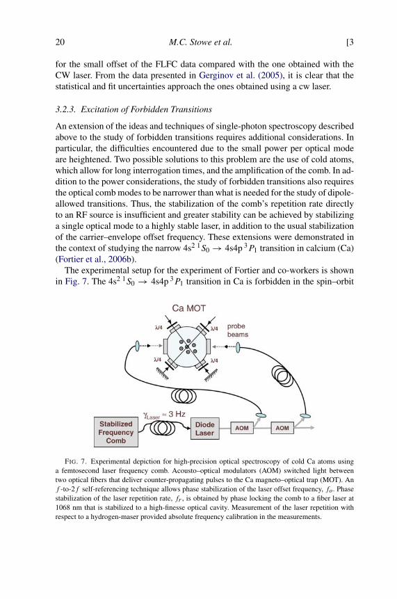
The experimental setup for the experiment of Fortier and co-workers is shownin Fig. 7. The 4s2 1S0 → 4s4p 3P1 transition in Ca is forbidden in the spin–orbit
FIG. 7. Experimental depiction for high-precision optical spectroscopy of cold Ca atoms usinga femtosecond laser frequency comb. Acousto–optical modulators (AOM) switched light betweentwo optical fibers that deliver counter-propagating pulses to the Ca magneto–optical trap (MOT). Anf -to-2f self-referencing technique allows phase stabilization of the laser offset frequency, fo. Phasestabilization of the laser repetition rate, fr , is obtained by phase locking the comb to a fiber laser at1068 nm that is stabilized to a high-finesse optical cavity. Measurement of the laser repetition withrespect to a hydrogen-maser provided absolute frequency calibration in the measurements.
3] DIRECT FREQUENCY COMB SPECTROSCOPY 21
approximation and has a natural linewidth of 374 Hz (Degenhardt et al., 2005),and this transition has been studied extensively as a optical frequency standard(Degenhardt et al., 2005; Oates et al., 2000). In this experiment, the frequencycomb was derived from an octave-spanning mode-locked Ti:sapphire laser with a≈1 GHz repetition rate (Fortier et al., 2006a). Due to the transmission of the out-put coupler, the output power of the laser peaked around the 657 nm wavelengthneeded to excite the 4s2 1S0 → 4s4p 3P1 transition. The power per mode at thiswavelength was ≈1 µW. With this type of power and the small dipole matrix ele-ment of the transition, one has Rabi frequencies of ∼10 kHz. In order to achievesizable population transfer, it is necessary to have interrogation times of ∼10 µs.These types of interrogation times can be achieved with moderately cooled atomswith temperatures of a few millikelvin.
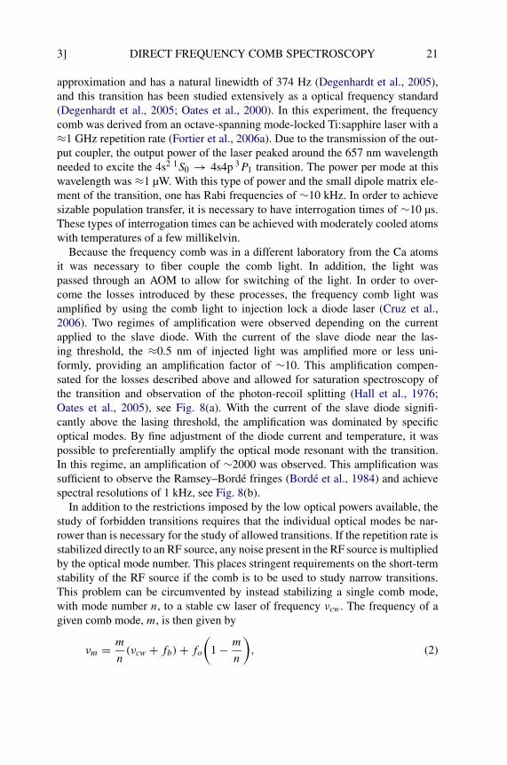
Because the frequency comb was in a different laboratory from the Ca atomsit was necessary to fiber couple the comb light. In addition, the light waspassed through an AOM to allow for switching of the light. In order to over-come the losses introduced by these processes, the frequency comb light wasamplified by using the comb light to injection lock a diode laser (Cruz et al.,2006). Two regimes of amplification were observed depending on the currentapplied to the slave diode. With the current of the slave diode near the las-ing threshold, the ≈0.5 nm of injected light was amplified more or less uni-formly, providing an amplification factor of ∼10. This amplification compen-sated for the losses described above and allowed for saturation spectroscopy ofthe transition and observation of the photon-recoil splitting (Hall et al., 1976;Oates et al., 2005), see Fig. 8(a). With the current of the slave diode signifi-cantly above the lasing threshold, the amplification was dominated by specificoptical modes. By fine adjustment of the diode current and temperature, it waspossible to preferentially amplify the optical mode resonant with the transition.In this regime, an amplification of ∼2000 was observed. This amplification wassufficient to observe the Ramsey–Bordé fringes (Bordé et al., 1984) and achievespectral resolutions of 1 kHz, see Fig. 8(b).
In addition to the restrictions imposed by the low optical powers available, thestudy of forbidden transitions requires that the individual optical modes be nar-rower than is necessary for the study of allowed transitions. If the repetition rate isstabilized directly to an RF source, any noise present in the RF source is multipliedby the optical mode number. This places stringent requirements on the short-termstability of the RF source if the comb is to be used to study narrow transitions.This problem can be circumvented by instead stabilizing a single comb mode,with mode number n, to a stable cw laser of frequency νcw. The frequency of agiven comb mode, m, is then given by
(2)νm = m
n(νcw + fb)+ fo
(1 − m
n
),
22 M.C. Stowe et al. [3
FIG. 8. (a) Saturation absorption dip observed on the Doppler profile of the Ca clock transitionusing two counter-propagating pulses. The double peak is the photon-recoil doublet. (b) Time-resolvedoptical Bordé–Ramsey fringes.
where fb is the heterodyne beat signal between the comb mode n and the cw laser.The frequency νm can be scanned by changing the frequency of the heterodynebeat note fb while the frequency comb is stabilized to light from a cw fiber laserat 1068 nm. The cw fiber laser was stabilized by doubling a portion of the lightand referencing it to a ultrastable optical cavity (Young et al., 1999). The residuallinewidth of the light at 1068 nm was ∼1 Hz. This stability was transferred to theentire bandwidth of the comb, providing a sufficiently narrow linewidth for thespectroscopy of the 4s2 1S0 → 4s4p 3P1 transition.
3.3. MULTI-PHOTON DFCS
Direct frequency comb spectroscopy is not only useful for single-photon transi-tions but also multi-photon transitions. Two general cases exist in the context oftwo-photon transitions, those with an intermediate resonance and those in whichthe pulse spectrum is far detuned from an intermediate resonance. In the casewhere one mode is resonant with the intermediate state, the system can often beunderstood by considering only two modes. However, when there is no interme-
3] DIRECT FREQUENCY COMB SPECTROSCOPY 23
diate resonance in the spectrum it should be noted that if one pair of comb modesis two-photon resonant, then all modes will form a resonant pair due to the equalspacing of modes.
3.3.1. Multi-Photon DFCS of Rubidium
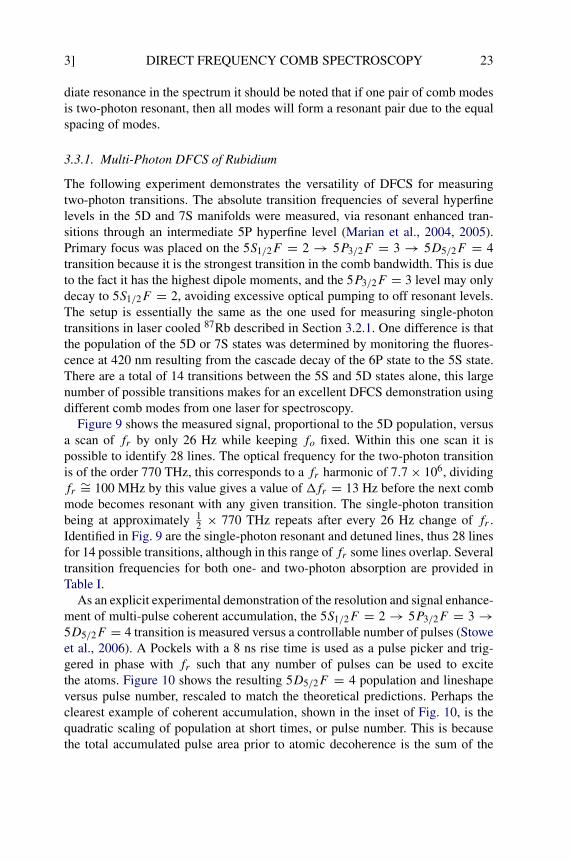
The following experiment demonstrates the versatility of DFCS for measuringtwo-photon transitions. The absolute transition frequencies of several hyperfinelevels in the 5D and 7S manifolds were measured, via resonant enhanced tran-sitions through an intermediate 5P hyperfine level (Marian et al., 2004, 2005).Primary focus was placed on the 5S1/2F = 2 → 5P3/2F = 3 → 5D5/2F = 4transition because it is the strongest transition in the comb bandwidth. This is dueto the fact it has the highest dipole moments, and the 5P3/2F = 3 level may onlydecay to 5S1/2F = 2, avoiding excessive optical pumping to off resonant levels.The setup is essentially the same as the one used for measuring single-photontransitions in laser cooled 87Rb described in Section 3.2.1. One difference is thatthe population of the 5D or 7S states was determined by monitoring the fluores-cence at 420 nm resulting from the cascade decay of the 6P state to the 5S state.There are a total of 14 transitions between the 5S and 5D states alone, this largenumber of possible transitions makes for an excellent DFCS demonstration usingdifferent comb modes from one laser for spectroscopy.
Figure 9 shows the measured signal, proportional to the 5D population, versusa scan of fr by only 26 Hz while keeping fo fixed. Within this one scan it ispossible to identify 28 lines. The optical frequency for the two-photon transitionis of the order 770 THz, this corresponds to a fr harmonic of 7.7 × 10⁶, dividingfr ∼= 100 MHz by this value gives a value of �fr = 13 Hz before the next combmode becomes resonant with any given transition. The single-photon transitionbeing at approximately 1
2 × 770 THz repeats after every 26 Hz change of fr .Identified in Fig. 9 are the single-photon resonant and detuned lines, thus 28 linesfor 14 possible transitions, although in this range of fr some lines overlap. Severaltransition frequencies for both one- and two-photon absorption are provided inTable I.
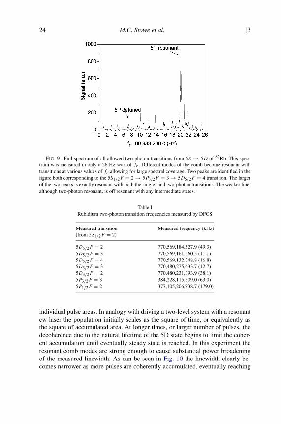
As an explicit experimental demonstration of the resolution and signal enhance-ment of multi-pulse coherent accumulation, the 5S1/2F = 2 → 5P3/2F = 3 →5D5/2F = 4 transition is measured versus a controllable number of pulses (Stoweet al., 2006). A Pockels with a 8 ns rise time is used as a pulse picker and trig-gered in phase with fr such that any number of pulses can be used to excitethe atoms. Figure 10 shows the resulting 5D5/2F = 4 population and lineshapeversus pulse number, rescaled to match the theoretical predictions. Perhaps theclearest example of coherent accumulation, shown in the inset of Fig. 10, is thequadratic scaling of population at short times, or pulse number. This is becausethe total accumulated pulse area prior to atomic decoherence is the sum of the
24 M.C. Stowe et al. [3
FIG. 9. Full spectrum of all allowed two-photon transitions from 5S → 5D of 87Rb. This spec-trum was measured in only a 26 Hz scan of fr . Different modes of the comb become resonant withtransitions at various values of fr allowing for large spectral coverage. Two peaks are identified in thefigure both corresponding to the 5S1/2F = 2 → 5P3/2F = 3 → 5D5/2F = 4 transition. The largerof the two peaks is exactly resonant with both the single- and two-photon transitions. The weaker line,although two-photon resonant, is off resonant with any intermediate states.
Table IRubidium two-photon transition frequencies measured by DFCS
Measured transition(from 5S1/2F = 2)
Measured frequency (kHz)
5D5/2F = 2 770,569,184,527.9 (49.3)5D5/2F = 3 770,569,161,560.5 (11.1)5D5/2F = 4 770,569,132,748.8 (16.8)5D3/2F = 3 770,480,275,633.7 (12.7)5D3/2F = 2 770,480,231,393.9 (38.1)5P3/2F = 3 384,228,115,309.0 (63.0)5P1/2F = 2 377,105,206,938.7 (179.0)
individual pulse areas. In analogy with driving a two-level system with a resonantcw laser the population initially scales as the square of time, or equivalently asthe square of accumulated area. At longer times, or larger number of pulses, thedecoherence due to the natural lifetime of the 5D state begins to limit the coher-ent accumulation until eventually steady state is reached. In this experiment theresonant comb modes are strong enough to cause substantial power broadeningof the measured linewidth. As can be seen in Fig. 10 the linewidth clearly be-comes narrower as more pulses are coherently accumulated, eventually reaching
3] DIRECT FREQUENCY COMB SPECTROSCOPY 25
FIG. 10. Shown in (a) is the excited state population versus pulse number. Notice two features inparticular, for short times the scaling is quadratic versus pulse number (see inset), and the populationreaches steady state at approximately 80 pulses. Scanning fo recovers the lineshape versus pulse num-ber shown in (b). The power broadened asymptotic linewidth of 2.2 MHz is reached at approximately80 pulses.
the asymptotic power broadened linewidth of 2.2 MHz at 80 pulses. In principlethe resolution obtainable by DFCS is only limited by decoherence mechanisms,typically due to the atomic transition because modern fs comb linewidths can bereduced to the 1 Hz level.
To determine the linecenter with high accuracy it is necessary to conduct ahigher resolution scan of the line of interest. Several sources of systematic errormust be carefully addressed to determine the unperturbed linecenter of interest.For all measurements the fs pulses are counter-propagated through the same setof atoms within the MOT to balance the radiation pressure. Provided the intensi-ties of the two counter-propagating beams are well matched the net momentumtransfer along the probing direction via photon scattering, primarily from the 5P
26 M.C. Stowe et al. [3
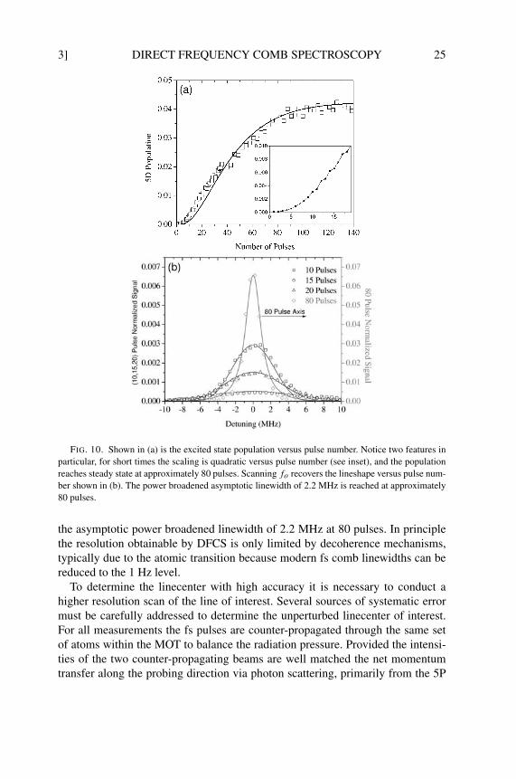
FIG. 11. The measured linecenter shift of the 5D5/2F = 4 level versus time relative to an arbi-trary reference value. For times below approximately 40 µs the fs comb power is increasing as theLCD shutter used in this experiment turns on, after 40 µs the power is constant. Three cases are pre-sented for different intermediate state detunings, all are nominally on resonance with 5D5/2F = 4.Two effects may be seen in this data, first the Stark shift is approximately equal and opposite aboutthe 0 MHz detuning result for the ±4 MHz detuning cases. Secondly, notice when the fs comb poweris constant the Stark shift is constant (red and blue detunings). However, the on resonance case under-goes significant accumulative Doppler shift due to radiation pressure from the residual intensity andalignment mismatch between the counter-propagating probe beams.
states, is significantly reduced. Repeated scattering also heats the atomic ensem-ble, broadening the linewidth. Similarly a residual net intensity imbalance of theprobe beams can accelerate the atoms resulting in a Doppler shift of the measuredlinecenters. The linecenter results reported in this review are based on measur-ing and fitting the linecenter versus time then extrapolating to zero interrogationtime. One interesting result is that for resonantly enhanced two-photon transitionsthe comb mode connecting the 5S1/2F = 2 → 5P3/2F = 3 transition can beeither resonant, blue detuned, or red detuned. By detuning the comb from exactintermediate resonance the heating rate is greatly reduced (Marian et al., 2004).
Another systematic error commonly encountered in two-photon transitions isthe AC Stark shift due to off-resonant intermediate states. Again in this case focusis placed on the 5S1/2F = 2 → 5P3/2F = 3 → 5D5/2F = 4 transition which issomewhat simplified because transitions to the final state are only allowed via the5P3/2F = 3 intermediate state due to hyperfine selection rules. A measurement ofthe 5D5/2F = 4 linecenter versus time, shown in Fig. 11, illustrates the positiveor negative Stark shift as a function of detuning from the intermediate state. Thisemphasizes the importance of being exactly on resonance with the intermediatestate when conducting highly accurate spectroscopy, but also that if the comb ismade exactly resonant the Stark shift is reduced. Furthermore it should be men-
3] DIRECT FREQUENCY COMB SPECTROSCOPY 27
tioned that, due to the regular spacing of modes, when one mode is resonant withthe intermediate state then for every mode detuned to the red of the intermediateresonance there is one to the blue side with an equal detuning. To within limitsdue to the spectral shape of the pulse the Stark shifts from off resonant modestends to cancel out, regardless of the spectral phases of the individual modes.
3.3.2. Multi-Photon DFCS of Cesium
As discussed in Section 3.3, two-photon spectroscopy is greatly enhanced in thecase where the two-photons are resonant with an intermediate state. While thisenhancement can be accomplished using the two degrees of frequency controlavailable with the comb as discussed above, it is also possible to utilize the mo-tion of the atoms to eliminate the need to fine tune both the carrier–envelopeoffset frequency and the repetition rate. This Doppler-induced enhancement wasdemonstrated in the work of Mbele et al. (in preparation).
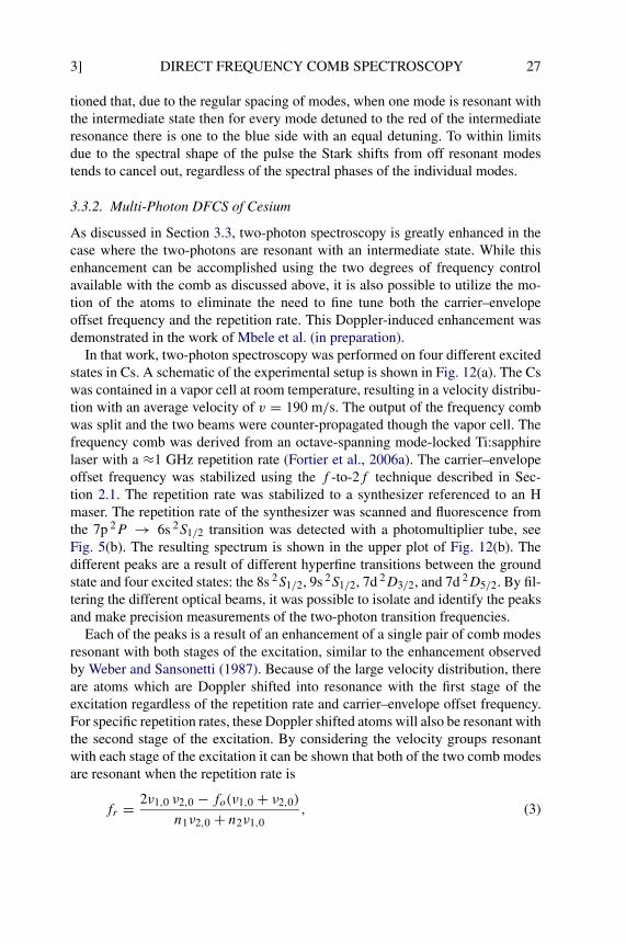
In that work, two-photon spectroscopy was performed on four different excitedstates in Cs. A schematic of the experimental setup is shown in Fig. 12(a). The Cswas contained in a vapor cell at room temperature, resulting in a velocity distribu-tion with an average velocity of v = 190 m/s. The output of the frequency combwas split and the two beams were counter-propagated though the vapor cell. Thefrequency comb was derived from an octave-spanning mode-locked Ti:sapphirelaser with a ≈1 GHz repetition rate (Fortier et al., 2006a). The carrier–envelopeoffset frequency was stabilized using the f -to-2f technique described in Sec-tion 2.1. The repetition rate was stabilized to a synthesizer referenced to an Hmaser. The repetition rate of the synthesizer was scanned and fluorescence fromthe 7p 2P → 6s 2S1/2 transition was detected with a photomultiplier tube, seeFig. 5(b). The resulting spectrum is shown in the upper plot of Fig. 12(b). Thedifferent peaks are a result of different hyperfine transitions between the groundstate and four excited states: the 8s 2S1/2, 9s 2S1/2, 7d 2D3/2, and 7d 2D5/2. By fil-tering the different optical beams, it was possible to isolate and identify the peaksand make precision measurements of the two-photon transition frequencies.
Each of the peaks is a result of an enhancement of a single pair of comb modesresonant with both stages of the excitation, similar to the enhancement observedby Weber and Sansonetti (1987). Because of the large velocity distribution, thereare atoms which are Doppler shifted into resonance with the first stage of theexcitation regardless of the repetition rate and carrier–envelope offset frequency.For specific repetition rates, these Doppler shifted atoms will also be resonant withthe second stage of the excitation. By considering the velocity groups resonantwith each stage of the excitation it can be shown that both of the two comb modesare resonant when the repetition rate is
(3)fr = 2ν1,0 ν2,0 − fo(ν1,0 + ν2,0)
n1ν2,0 + n2ν1,0,

28 M.C. Stowe et al. [3
were ν1,0 and ν2,0 are the Doppler-free frequencies of the first and second stagesof excitation, respectively, of the two-photon transition. This eliminates the needfor independent adjustment of the carrier–envelope offset frequency in order toachieve the double resonance condition. Because the velocity class that is exciteddepends on the frequency of both stages of the two-photon excitation, the spec-trum also provides information concerning the intermediate state frequency.
The velocity selective enhancement selects out a single pair of comb modes.Consequently, one can consider the excitation of a given state as equivalentto the excitation by two cw lasers. The middle trace in Fig. 12(b) shows the
FIG. 12. Two-photon excitation of Cs states. (a) shows a block diagram of the experiment. Thetop trace in (b) shows the spectrum obtained with an unfiltered comb. Four different excited statesare present. The middle trace in (b) shows the spectrum obtained by filtering the comb so that onlythe 6s 2S1/2 → 6p 2P3/2 → 8s 2S1/2 transition contributes. The bottom trace shows the calculatedspectrum.

3] DIRECT FREQUENCY COMB SPECTROSCOPY 29
experimental spectrum acquired by filtering the two arms to observe only the6s 2S1/2 → 9s 2S1/2 transition through the 6p 2P3/2 intermediate state. Belowit is the calculated spectrum generated by integrating the two-photon formula,Eq. (1), over the velocity distribution. It is possible to determine the frequencyof the transitions, as well as the hyperfine constants of the states, by calculatingspectra with different transition frequencies and hyperfine constants and match-ing the calculations to the experimental spectra. In the experiment of Mbele etal. (in preparation), the frequencies and hyperfine coefficients of the states weredetermined with an accuracy of 50–200 kHz.
3.4. SHORT WAVELENGTH DFCS
One of the most promising future applications of DFCS is to truly take advantageof the phase coherence of the comb combined with the efficient nonlinear con-version enabled by high peak intensities. Already some experiments have beenconducted by frequency mixing the fs pulses to shorter wavelengths where cwlasers are not easily accessible. There are two experiments conducted to date uti-lizing multi-pulse quantum interference for spectroscopy in the VUV spectrum.The first demonstration of this technique used two-photon absorption at 212 nmin krypton by pairs of phase coherent pulses (Witte et al., 2005). The most recent
FIG. 13. Measured xenon ion yield versus fr for 2, 3, 4, 5, 6 pulses. The strength of the pulsesdecreases versus pulse number as the amplifier inversion decays. These results emphasize severalaspects of DFCS. The signal linewidth reduces versus the number of pulses used, note it is sinusoidalfor two pulses similar to Ramsey spectroscopy. Secondly, the single resonant line repeats periodicallydue to the comb structure of the laser. [Reprinted with permission from Zinkstok et al. (2006).]
© 2006 Elsevier
30 M.C. Stowe et al. [4
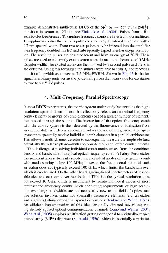
example demonstrates multi-pulse DFCS of the 5p6 1S0 → 5p5 (2P3/2)5d[ 12 ]1
transition in xenon at 125 nm, see Zinkstok et al. (2006). Pulses from a Rb-atomic-clock-referenced Ti:sapphire frequency comb are injected into a multipassTi:sapphire amplifier that outputs pulses of about 25 µJ centered at 750 nm with a0.7 nm spectral width. From two to six pulses may be injected into the amplifierthen frequency doubled in BBO and subsequently tripled in either oxygen or kryp-ton. The resulting pulses are phase coherent and have an energy of 50 fJ. Thesepulses are used to coherently excite xenon atoms in an atomic beam of <10 MHzDoppler width. The excited atoms are then ionized by a second pulse and the ionsare detected. Using this technique the authors were able to scan fr and recover atransition linewidth as narrow as 7.5 MHz FWHM. Shown in Fig. 13 is the ionsignal in arbitrary units versus the fr detuning from the mean value for excitationby two to six VUV pulses.
4. Multi-Frequency Parallel Spectroscopy
In most DFCS experiments, the atomic system under study has acted as the high-resolution spectral discriminator that effectively selects an individual frequencycomb element (or groups of comb elements) out of a greater number of elementsthat passed through the sample. The interaction of the optical frequency combwith the atomic system is then detected by the fluorescence or ionization froman excited state. A different approach involves the use of a high-resolution spec-trometer to spectrally resolve individual comb elements in a parallel architecture.This allows a multi-channel detector to subsequently measure the amplitude (andpotentially the relative phase—with appropriate reference) of the comb elements.
The challenge of resolving individual comb modes arises from the combineddensity and bandwidth of a typical optical frequency comb. A Fabry–Perot etalonhas sufficient finesse to easily resolve the individual modes of a frequency combwith mode spacing below 100 MHz; however, the free spectral range of suchan etalon does not typically exceed 100 GHz, which limits the bandwidth overwhich it can be used. On the other hand, grating-based spectrometers of reason-able size and cost can cover hundreds of THz, but the typical resolution doesnot exceed 10 GHz, which is insufficient to isolate individual modes of mostfemtosecond frequency combs. Such conflicting requirements of high resolu-tion over large bandwidths are not necessarily new to the field of optics, andone solution involves using two spectrally dispersive elements (e.g. an etalonand a grating) along orthogonal spatial dimensions (Jenkins and White, 1976).An efficient implementation of this idea, originally directed toward separat-ing densely-spaced optical communications channels (Xiao and Weiner, 2004;Wang et al., 2005) employs a diffraction grating orthogonal to a virtually-imagedphased array (VIPA) disperser (Shirasaki, 1996), which is essentially a variation

4] DIRECT FREQUENCY COMB SPECTROSCOPY 31
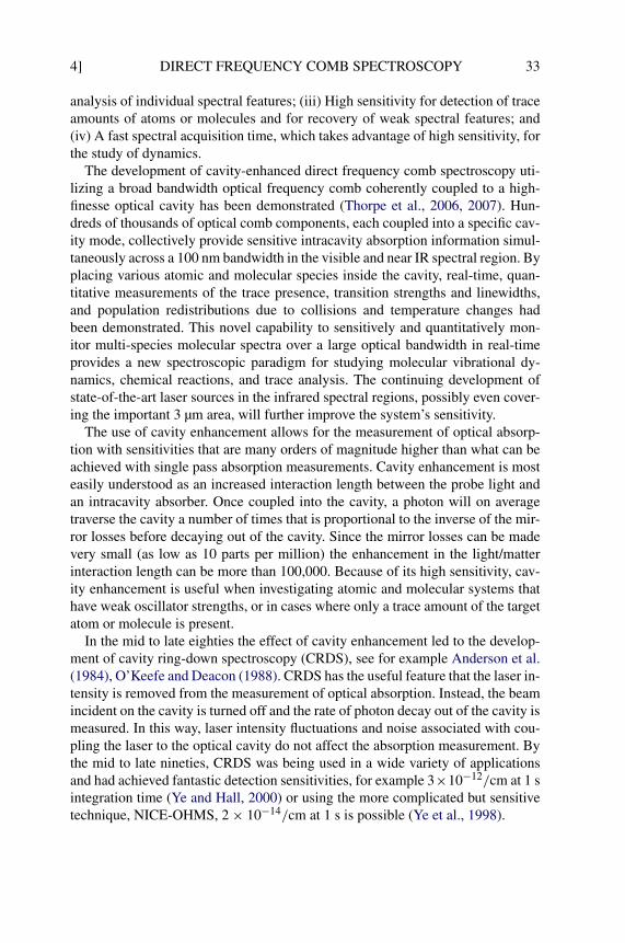
FIG. 14. A high resolution virtually-imaged phased array (VIPA) disperser is used in combina-tion with a lower resolution diffraction grating to spatially resolve the filtered frequency comb of afrequency-stabilized, broadband Ti:sapphire femtosecond laser. (a) The spectrometer output in the re-gion of 633 nm, as measured on a CCD element, consists of a 2-d array of the frequency comb modes,where each dot of this image represents an individual mode. Within a column (Y), which is tilted bythe grating dispersion, the dots are separated by the mode spacing (3 GHz in this case). Within eachrow (X), the dots are separated by the VIPA free spectral range (FSR 50 GHz in this case). (b) Sameframe as above, but now with iodine cell present. Note that some modes are missing or noticeablyattenuated due to the presence of the iodine.
on the well-known plane-parallel etalon. In this case, the grating should providespectral resolution better than that of the VIPA’s free spectral range (FSR).
A high-resolution spectrometer designed for resolving individual comb modesis diagrammed in Fig. 14 (Diddams et al., 2006). The VIPA is a plane-parallelsolid glass etalon, where the input beam is focused to a line and injected at an
32 M.C. Stowe et al. [4
angle through an uncoated entrance window on the etalon’s front face. The re-mainder of the front face is coated with a high-reflective dielectric, while the backface has a dielectric coating with 96% reflectivity. The multiple reflections withinthe VIPA etalon interfere in such a way that the exiting beam has its differentfrequencies emerging at different angles. In this case, the VIPA has a free spec-tral range of 50 GHz, determined by its thickness and index of refraction. The2400 line/mm grating, used at a large angle of incidence and oriented with itsdispersive axis orthogonal to that of the VIPA, provides 20 GHz spectral resolu-tion that is sufficient to separate the various orders of the VIPA etalon.
The output of the VIPA/grating spectrometer is imaged onto a CCD cam-era, resulting in the array of dots, representing the individual comb modes, seeFig. 14(a). In this example, a frequency comb with elements spaced by 3 GHz wascreated by filtering the 1 GHz comb produced by a broad bandwidth Ti:sapphirelaser. Approximately 2200 individual modes have been resolved within a 6.5 THzbandwidth captured in a few millisecond exposure on the CCD, for clarity thebandwidth is restricted to 2.5 THz in Fig. 14. In the vertical direction of this im-age, the data repeats every 50 GHz (at the VIPA FSR), and adjacent columns arealso separated by the FSR of the VIPA. Full details on the indexing and countingof the numerous modes, as well as the frequency calibration are described in a re-cent publication (Diddams et al., 2007). The repetitive nature of the data is evidentin Fig. 14(b), which is an image acquired with the iodine vapor cell inserted in thebeam path. The cell is at room temperature and multi-passed to yield an equivalentlength of 2 m. As clearly seen, numerous modes which coincide with absorp-tion features of iodine are attenuated. Given the particular phase-locked valuesof fo and fr , the absolute frequency of each mode (or equivalently each CCDpixel) can be determined, thus providing a rapid means of identifying atomic ormolecular species. While the VIPA spectrometer resolution is presently 1.2 GHz(at 475 THz), spectroscopic features down to the linewidth of the comb lines canbe distinguished. Scanning the repetition rate or offset frequency of the laser en-ables one to scan out the full optical spectrum with a resolution suitable for thesystem under study (Diddams et al., 2007).
4.1. CAVITY ENHANCED DFCS
With every optical comb component efficiently coupled into a respective high-finesse cavity mode, one can establish a network of parallel channels for ultra-sensitive detection of molecular dynamics and trace analysis. This configurationprovides an ideal spectroscopic paradigm suitable for the next generation ofatomic and molecular measurements. The approach presents simultaneously thefollowing attractive characteristics: (i) A large spectral bandwidth allowing for theobservation of global energy level structure of many different atomic and mole-cular species; (ii) High spectral resolution for the identification and quantitative
4] DIRECT FREQUENCY COMB SPECTROSCOPY 33
analysis of individual spectral features; (iii) High sensitivity for detection of traceamounts of atoms or molecules and for recovery of weak spectral features; and(iv) A fast spectral acquisition time, which takes advantage of high sensitivity, forthe study of dynamics.
The development of cavity-enhanced direct frequency comb spectroscopy uti-lizing a broad bandwidth optical frequency comb coherently coupled to a high-finesse optical cavity has been demonstrated (Thorpe et al., 2006, 2007). Hun-dreds of thousands of optical comb components, each coupled into a specific cav-ity mode, collectively provide sensitive intracavity absorption information simul-taneously across a 100 nm bandwidth in the visible and near IR spectral region. Byplacing various atomic and molecular species inside the cavity, real-time, quan-titative measurements of the trace presence, transition strengths and linewidths,and population redistributions due to collisions and temperature changes hadbeen demonstrated. This novel capability to sensitively and quantitatively mon-itor multi-species molecular spectra over a large optical bandwidth in real-timeprovides a new spectroscopic paradigm for studying molecular vibrational dy-namics, chemical reactions, and trace analysis. The continuing development ofstate-of-the-art laser sources in the infrared spectral regions, possibly even cover-ing the important 3 µm area, will further improve the system’s sensitivity.
The use of cavity enhancement allows for the measurement of optical absorp-tion with sensitivities that are many orders of magnitude higher than what can beachieved with single pass absorption measurements. Cavity enhancement is mosteasily understood as an increased interaction length between the probe light andan intracavity absorber. Once coupled into the cavity, a photon will on averagetraverse the cavity a number of times that is proportional to the inverse of the mir-ror losses before decaying out of the cavity. Since the mirror losses can be madevery small (as low as 10 parts per million) the enhancement in the light/matterinteraction length can be more than 100,000. Because of its high sensitivity, cav-ity enhancement is useful when investigating atomic and molecular systems thathave weak oscillator strengths, or in cases where only a trace amount of the targetatom or molecule is present.
In the mid to late eighties the effect of cavity enhancement led to the develop-ment of cavity ring-down spectroscopy (CRDS), see for example Anderson et al.(1984), O’Keefe and Deacon (1988). CRDS has the useful feature that the laser in-tensity is removed from the measurement of optical absorption. Instead, the beamincident on the cavity is turned off and the rate of photon decay out of the cavity ismeasured. In this way, laser intensity fluctuations and noise associated with cou-pling the laser to the optical cavity do not affect the absorption measurement. Bythe mid to late nineties, CRDS was being used in a wide variety of applicationsand had achieved fantastic detection sensitivities, for example 3×10⁻¹²/cm at 1 sintegration time (Ye and Hall, 2000) or using the more complicated but sensitivetechnique, NICE-OHMS, 2 × 10⁻¹⁴/cm at 1 s is possible (Ye et al., 1998).
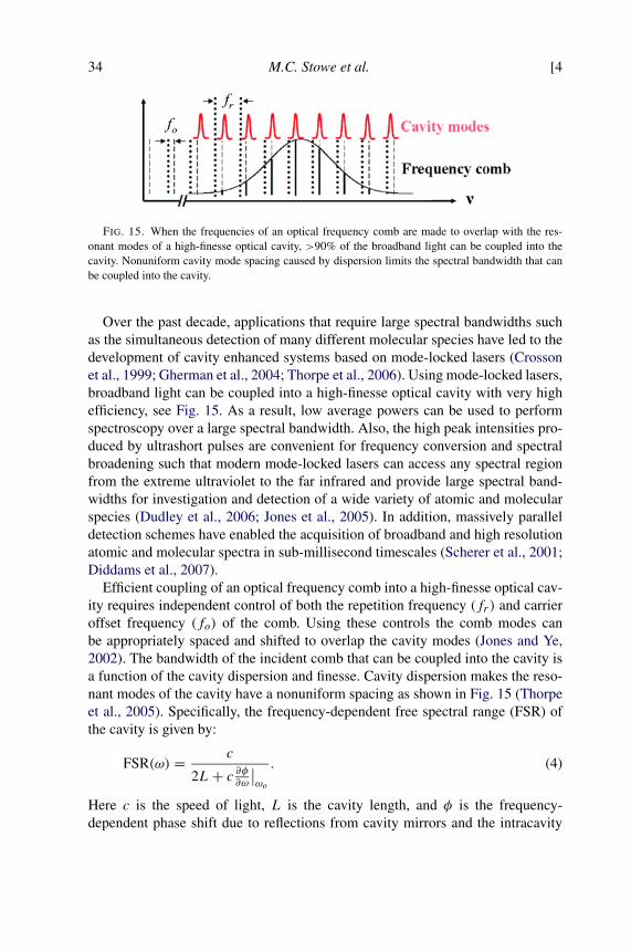
34 M.C. Stowe et al. [4
FIG. 15. When the frequencies of an optical frequency comb are made to overlap with the res-onant modes of a high-finesse optical cavity, >90% of the broadband light can be coupled into thecavity. Nonuniform cavity mode spacing caused by dispersion limits the spectral bandwidth that canbe coupled into the cavity.
Over the past decade, applications that require large spectral bandwidths suchas the simultaneous detection of many different molecular species have led to thedevelopment of cavity enhanced systems based on mode-locked lasers (Crossonet al., 1999; Gherman et al., 2004; Thorpe et al., 2006). Using mode-locked lasers,broadband light can be coupled into a high-finesse optical cavity with very highefficiency, see Fig. 15. As a result, low average powers can be used to performspectroscopy over a large spectral bandwidth. Also, the high peak intensities pro-duced by ultrashort pulses are convenient for frequency conversion and spectralbroadening such that modern mode-locked lasers can access any spectral regionfrom the extreme ultraviolet to the far infrared and provide large spectral band-widths for investigation and detection of a wide variety of atomic and molecularspecies (Dudley et al., 2006; Jones et al., 2005). In addition, massively paralleldetection schemes have enabled the acquisition of broadband and high resolutionatomic and molecular spectra in sub-millisecond timescales (Scherer et al., 2001;Diddams et al., 2007).
Efficient coupling of an optical frequency comb into a high-finesse optical cav-ity requires independent control of both the repetition frequency (fr) and carrieroffset frequency (fo) of the comb. Using these controls the comb modes canbe appropriately spaced and shifted to overlap the cavity modes (Jones and Ye,2002). The bandwidth of the incident comb that can be coupled into the cavity isa function of the cavity dispersion and finesse. Cavity dispersion makes the reso-nant modes of the cavity have a nonuniform spacing as shown in Fig. 15 (Thorpeet al., 2005). Specifically, the frequency-dependent free spectral range (FSR) ofthe cavity is given by:
(4)FSR(ω) = c
2L+ c ∂φ∂ω
∣∣ωo
.
Here c is the speed of light, L is the cavity length, and φ is the frequency-dependent phase shift due to reflections from cavity mirrors and the intracavity
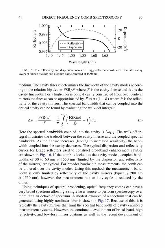
4] DIRECT FREQUENCY COMB SPECTROSCOPY 35
FIG. 16. The reflectivity and dispersion curves of Bragg reflectors constructed from alternatinglayers of silicon dioxide and niobium oxide centered at 1550 nm.
medium. The cavity finesse determines the linewidth of the cavity modes accord-ing to the relationship �ν = FSR/F where F is the cavity finesse and �ν is thecavity linewidth. For a high-finesse optical cavity constructed from two identicalmirrors the finesse can be approximated by F ≈ π/(1−R) where R is the reflec-tivity of the cavity mirrors. The spectral bandwidth that can be coupled into theoptical cavity can be found by evaluating the walk-off integral:
(5)�ν = FSR(ω)
F = 1
π
ω1/2∫0
(FSR(ω)
fr− 1
)dω.
Here the spectral bandwidth coupled into the cavity is 2ω1/2. The walk-off in-tegral illustrates the tradeoff between the cavity finesse and the coupled spectralbandwidth. As the finesse increases (leading to increased sensitivity) the band-width coupled into the cavity decreases. The typical dispersion and reflectivitycurves for Bragg reflectors used to construct broadband enhancement cavitiesare shown in Fig. 16. If the comb is locked to the cavity modes, coupled band-widths of 30 to 60 nm at 1550 nm (limited by the dispersion and reflectivityof the mirrors) are typical. For broader bandwidth measurements, the comb canbe dithered over the cavity modes. Using this method, the measurement band-width is only limited by reflectivity of the cavity mirrors (typically 200 nmat 1550 nm), however, the measurement rate or duty cycle is reduced by thedither.
Using techniques of spectral broadening, optical frequency combs can have avery broad spectrum allowing a single laser source to perform spectroscopy overmore than an octave of spectrum. A modest example of a spectrum that can begenerated using highly nonlinear fiber is shown in Fig. 17. Because of this, it istypically the cavity mirrors that limit the spectral bandwidth of cavity enhancedmeasurement systems. However, the continued development of broad-band, highreflectivity, and low-loss mirror coatings as well as the recent development of
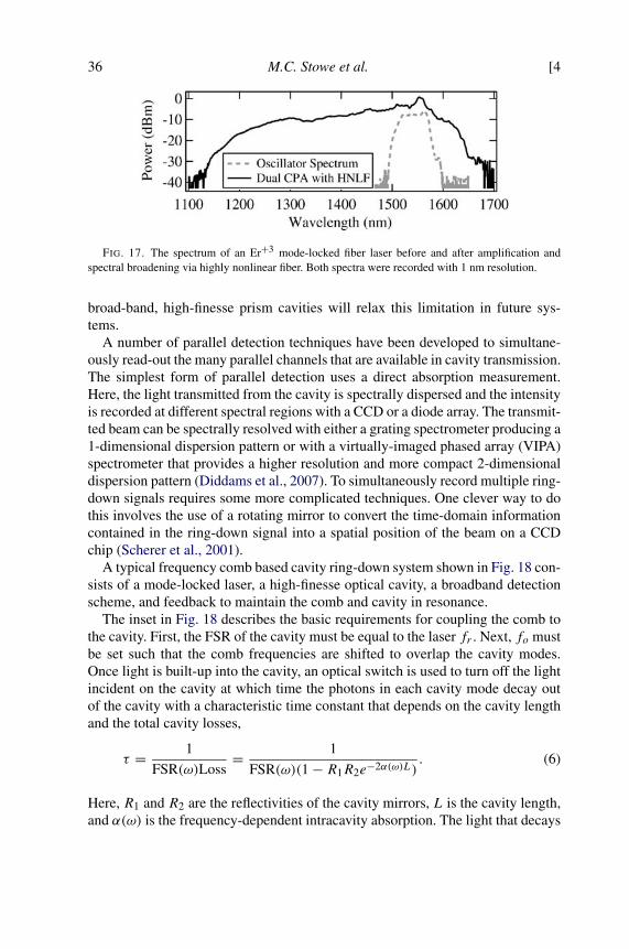
36 M.C. Stowe et al. [4
FIG. 17. The spectrum of an Er+3 mode-locked fiber laser before and after amplification andspectral broadening via highly nonlinear fiber. Both spectra were recorded with 1 nm resolution.
broad-band, high-finesse prism cavities will relax this limitation in future sys-tems.
A number of parallel detection techniques have been developed to simultane-ously read-out the many parallel channels that are available in cavity transmission.The simplest form of parallel detection uses a direct absorption measurement.Here, the light transmitted from the cavity is spectrally dispersed and the intensityis recorded at different spectral regions with a CCD or a diode array. The transmit-ted beam can be spectrally resolved with either a grating spectrometer producing a1-dimensional dispersion pattern or with a virtually-imaged phased array (VIPA)spectrometer that provides a higher resolution and more compact 2-dimensionaldispersion pattern (Diddams et al., 2007). To simultaneously record multiple ring-down signals requires some more complicated techniques. One clever way to dothis involves the use of a rotating mirror to convert the time-domain informationcontained in the ring-down signal into a spatial position of the beam on a CCDchip (Scherer et al., 2001).
A typical frequency comb based cavity ring-down system shown in Fig. 18 con-sists of a mode-locked laser, a high-finesse optical cavity, a broadband detectionscheme, and feedback to maintain the comb and cavity in resonance.
The inset in Fig. 18 describes the basic requirements for coupling the comb tothe cavity. First, the FSR of the cavity must be equal to the laser fr . Next, fo mustbe set such that the comb frequencies are shifted to overlap the cavity modes.Once light is built-up into the cavity, an optical switch is used to turn off the lightincident on the cavity at which time the photons in each cavity mode decay outof the cavity with a characteristic time constant that depends on the cavity lengthand the total cavity losses,
(6)τ = 1
FSR(ω)Loss= 1
FSR(ω)(1 − R1R2e−2α(ω)L).
Here, R1 and R2 are the reflectivities of the cavity mirrors, L is the cavity length,and α(ω) is the frequency-dependent intracavity absorption. The light that decays
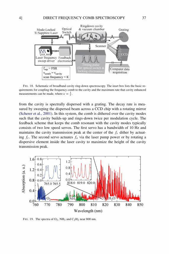
4] DIRECT FREQUENCY COMB SPECTROSCOPY 37
FIG. 18. Schematic of broadband cavity ring-down spectroscopy. The inset box lists the basic re-quirements for coupling the frequency comb to the cavity and the maximum rate that cavity enhancedmeasurements can be made, where κ = 1
τ .
from the cavity is spectrally dispersed with a grating. The decay rate is mea-sured by sweeping the dispersed beam across a CCD chip with a rotating mirror(Scherer et al., 2001). In this system, the comb is dithered over the cavity modessuch that the cavity builds-up and rings-down twice per modulation cycle. Thefeedback scheme that keeps the comb resonant with the cavity modes typicallyconsists of two low speed servos. The first servo has a bandwidth of 10 Hz andmaintains the cavity transmission peak at the center of the fr dither by actuat-ing fr . The second servo actuates fo via the laser pump power or by rotating adispersive element inside the laser cavity to maximize the height of the cavitytransmission peak.
FIG. 19. The spectra of O2, NH3 and C2H2 near 800 nm.
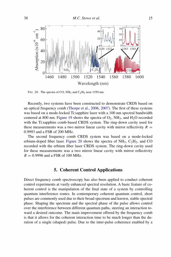
38 M.C. Stowe et al. [5
FIG. 20. The spectra of CO, NH3 and C2H2 near 1550 nm.
Recently, two systems have been constructed to demonstrate CRDS based onan optical frequency comb (Thorpe et al., 2006, 2007). The first of these systemswas based on a mode-locked Ti:sapphire laser with a 100 nm spectral bandwidthcentered at 800 nm. Figure 19 shows the spectra of O2, NH3, and H2O recordedwith the Ti:sapphire comb-based CRDS system. The ring-down cavity used forthese measurements was a two mirror linear cavity with mirror reflectivity R =0.9993 and a FSR of 200 MHz.
The second frequency comb CRDS system was based on a mode-lockederbium-doped fiber laser. Figure 20 shows the spectra of NH3, C2H2, and COrecorded with the erbium fiber laser CRDS system. The ring-down cavity usedfor these measurements was a two mirror linear cavity with mirror reflectivityR = 0.9996 and a FSR of 100 MHz.
5. Coherent Control Applications
Direct frequency comb spectroscopy has also been applied to conduct coherentcontrol experiments at vastly enhanced spectral resolution. A basic feature of co-herent control is the manipulation of the final state of a system by controllingquantum interference routes. In contemporary coherent quantum control, shortpulses are commonly used due to their broad spectrum and known, stable spectralphase. Shaping the spectrum and the spectral phase of the pulse allows controlover the interference between different quantum paths, steering an interaction to-ward a desired outcome. The main improvement offered by the frequency combis that it allows for the coherent interaction time to be much longer than the du-ration of a single (shaped) pulse. Due to the inter-pulse coherence enabled by a
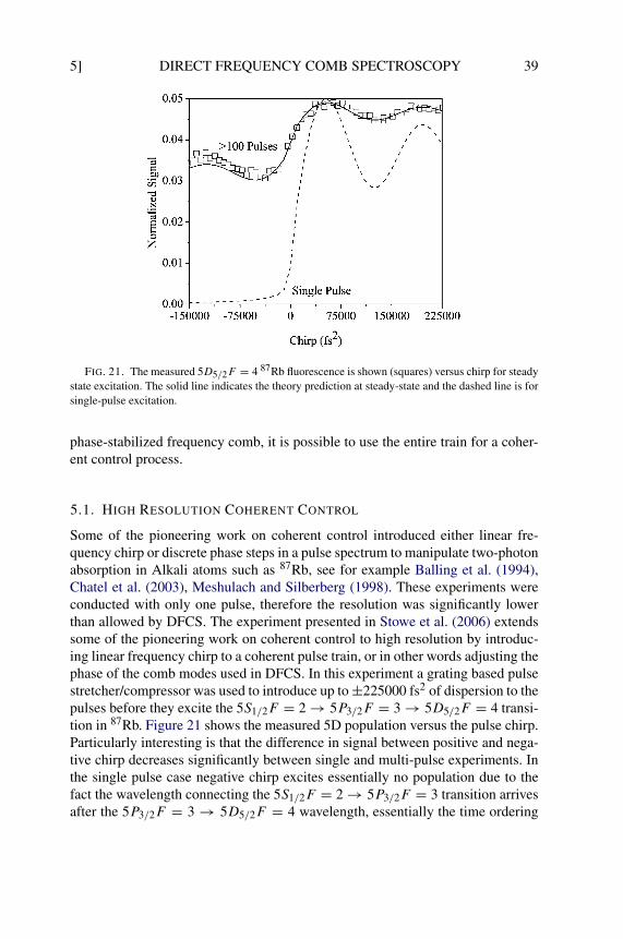
5] DIRECT FREQUENCY COMB SPECTROSCOPY 39
FIG. 21. The measured 5D5/2F = 4 87Rb fluorescence is shown (squares) versus chirp for steadystate excitation. The solid line indicates the theory prediction at steady-state and the dashed line is forsingle-pulse excitation.
phase-stabilized frequency comb, it is possible to use the entire train for a coher-ent control process.
5.1. HIGH RESOLUTION COHERENT CONTROL
Some of the pioneering work on coherent control introduced either linear fre-quency chirp or discrete phase steps in a pulse spectrum to manipulate two-photonabsorption in Alkali atoms such as 87Rb, see for example Balling et al. (1994),Chatel et al. (2003), Meshulach and Silberberg (1998). These experiments wereconducted with only one pulse, therefore the resolution was significantly lowerthan allowed by DFCS. The experiment presented in Stowe et al. (2006) extendssome of the pioneering work on coherent control to high resolution by introduc-ing linear frequency chirp to a coherent pulse train, or in other words adjusting thephase of the comb modes used in DFCS. In this experiment a grating based pulsestretcher/compressor was used to introduce up to ±225000 fs2 of dispersion to thepulses before they excite the 5S1/2F = 2 → 5P3/2F = 3 → 5D5/2F = 4 transi-tion in 87Rb. Figure 21 shows the measured 5D population versus the pulse chirp.Particularly interesting is that the difference in signal between positive and nega-tive chirp decreases significantly between single and multi-pulse experiments. Inthe single pulse case negative chirp excites essentially no population due to thefact the wavelength connecting the 5S1/2F = 2 → 5P3/2F = 3 transition arrivesafter the 5P3/2F = 3 → 5D5/2F = 4 wavelength, essentially the time ordering
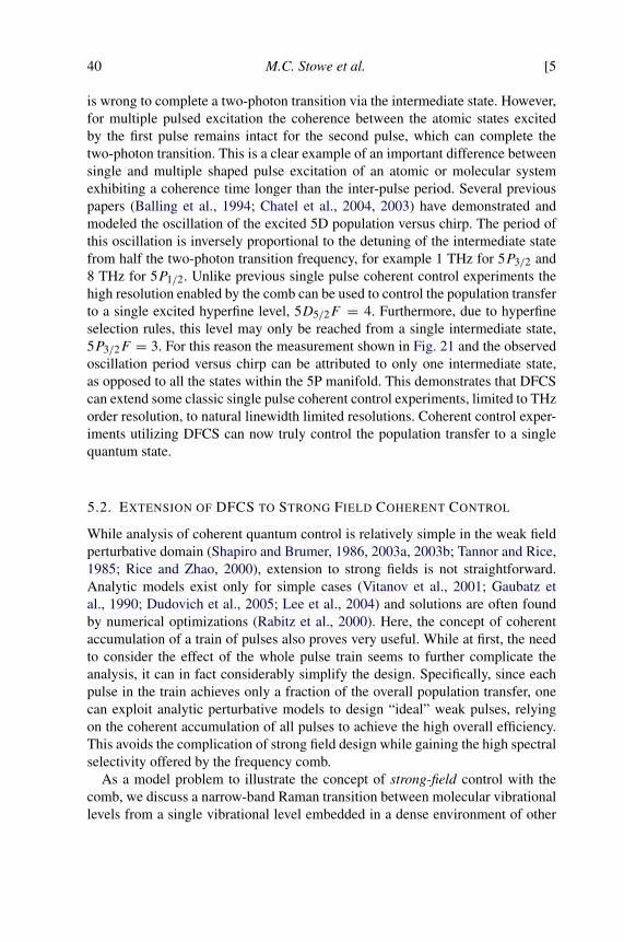
40 M.C. Stowe et al. [5
is wrong to complete a two-photon transition via the intermediate state. However,for multiple pulsed excitation the coherence between the atomic states excitedby the first pulse remains intact for the second pulse, which can complete thetwo-photon transition. This is a clear example of an important difference betweensingle and multiple shaped pulse excitation of an atomic or molecular systemexhibiting a coherence time longer than the inter-pulse period. Several previouspapers (Balling et al., 1994; Chatel et al., 2004, 2003) have demonstrated andmodeled the oscillation of the excited 5D population versus chirp. The period ofthis oscillation is inversely proportional to the detuning of the intermediate statefrom half the two-photon transition frequency, for example 1 THz for 5P3/2 and8 THz for 5P1/2. Unlike previous single pulse coherent control experiments thehigh resolution enabled by the comb can be used to control the population transferto a single excited hyperfine level, 5D5/2F = 4. Furthermore, due to hyperfineselection rules, this level may only be reached from a single intermediate state,5P3/2F = 3. For this reason the measurement shown in Fig. 21 and the observedoscillation period versus chirp can be attributed to only one intermediate state,as opposed to all the states within the 5P manifold. This demonstrates that DFCScan extend some classic single pulse coherent control experiments, limited to THzorder resolution, to natural linewidth limited resolutions. Coherent control exper-iments utilizing DFCS can now truly control the population transfer to a singlequantum state.
5.2. EXTENSION OF DFCS TO STRONG FIELD COHERENT CONTROL
While analysis of coherent quantum control is relatively simple in the weak fieldperturbative domain (Shapiro and Brumer, 1986, 2003a, 2003b; Tannor and Rice,1985; Rice and Zhao, 2000), extension to strong fields is not straightforward.Analytic models exist only for simple cases (Vitanov et al., 2001; Gaubatz etal., 1990; Dudovich et al., 2005; Lee et al., 2004) and solutions are often foundby numerical optimizations (Rabitz et al., 2000). Here, the concept of coherentaccumulation of a train of pulses also proves very useful. While at first, the needto consider the effect of the whole pulse train seems to further complicate theanalysis, it can in fact considerably simplify the design. Specifically, since eachpulse in the train achieves only a fraction of the overall population transfer, onecan exploit analytic perturbative models to design “ideal” weak pulses, relyingon the coherent accumulation of all pulses to achieve the high overall efficiency.This avoids the complication of strong field design while gaining the high spectralselectivity offered by the frequency comb.
As a model problem to illustrate the concept of strong-field control with thecomb, we discuss a narrow-band Raman transition between molecular vibrationallevels from a single vibrational level embedded in a dense environment of other
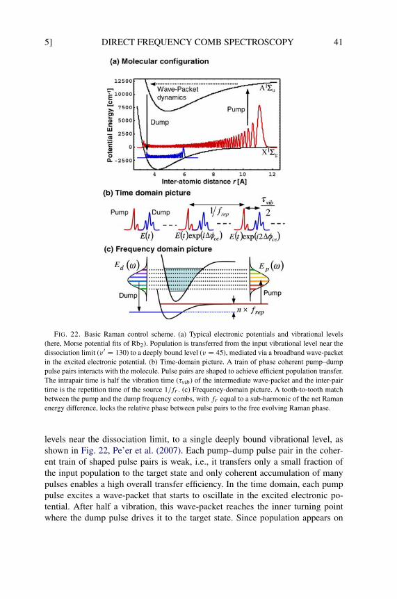
5] DIRECT FREQUENCY COMB SPECTROSCOPY 41
FIG. 22. Basic Raman control scheme. (a) Typical electronic potentials and vibrational levels(here, Morse potential fits of Rb2). Population is transferred from the input vibrational level near thedissociation limit (v′ = 130) to a deeply bound level (v = 45), mediated via a broadband wave-packetin the excited electronic potential. (b) Time-domain picture. A train of phase coherent pump–dumppulse pairs interacts with the molecule. Pulse pairs are shaped to achieve efficient population transfer.The intrapair time is half the vibration time (τvib) of the intermediate wave-packet and the inter-pairtime is the repetition time of the source 1/fr . (c) Frequency-domain picture. A tooth-to-tooth matchbetween the pump and the dump frequency combs, with fr equal to a sub-harmonic of the net Ramanenergy difference, locks the relative phase between pulse pairs to the free evolving Raman phase.
levels near the dissociation limit, to a single deeply bound vibrational level, asshown in Fig. 22, Pe’er et al. (2007). Each pump–dump pulse pair in the coher-ent train of shaped pulse pairs is weak, i.e., it transfers only a small fraction ofthe input population to the target state and only coherent accumulation of manypulses enables a high overall transfer efficiency. In the time domain, each pumppulse excites a wave-packet that starts to oscillate in the excited electronic po-tential. After half a vibration, this wave-packet reaches the inner turning pointwhere the dump pulse drives it to the target state. Since population appears on
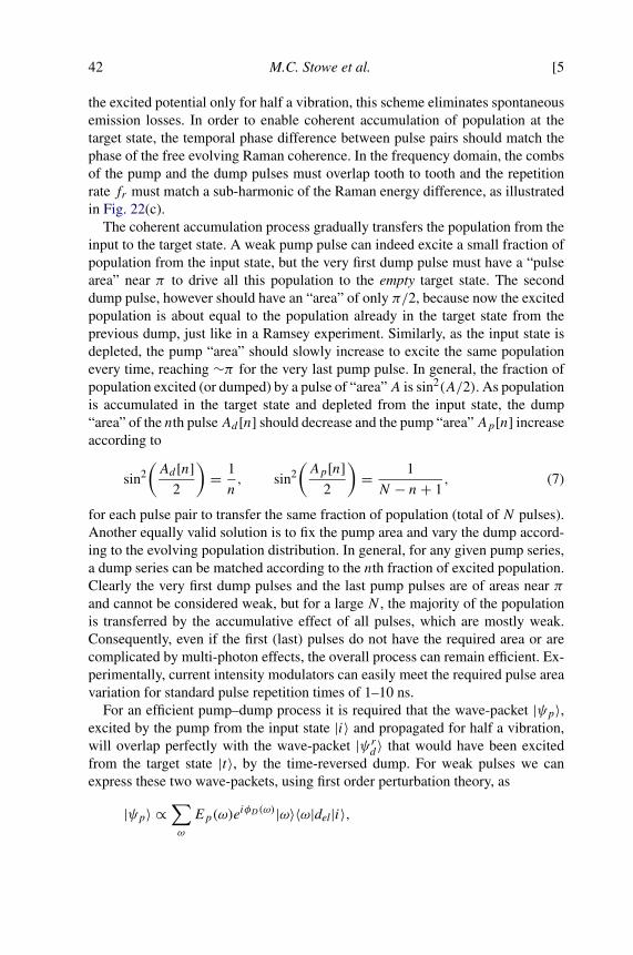
42 M.C. Stowe et al. [5
the excited potential only for half a vibration, this scheme eliminates spontaneousemission losses. In order to enable coherent accumulation of population at thetarget state, the temporal phase difference between pulse pairs should match thephase of the free evolving Raman coherence. In the frequency domain, the combsof the pump and the dump pulses must overlap tooth to tooth and the repetitionrate fr must match a sub-harmonic of the Raman energy difference, as illustratedin Fig. 22(c).
The coherent accumulation process gradually transfers the population from theinput to the target state. A weak pump pulse can indeed excite a small fraction ofpopulation from the input state, but the very first dump pulse must have a “pulsearea” near π to drive all this population to the empty target state. The seconddump pulse, however should have an “area” of only π/2, because now the excitedpopulation is about equal to the population already in the target state from theprevious dump, just like in a Ramsey experiment. Similarly, as the input state isdepleted, the pump “area” should slowly increase to excite the same populationevery time, reaching ∼π for the very last pump pulse. In general, the fraction ofpopulation excited (or dumped) by a pulse of “area”A is sin2(A/2). As populationis accumulated in the target state and depleted from the input state, the dump“area” of the nth pulseAd [n] should decrease and the pump “area”Ap[n] increaseaccording to
(7)sin2(Ad [n]
2
)= 1
n, sin2
(Ap[n]
2
)= 1
N − n+ 1,
for each pulse pair to transfer the same fraction of population (total of N pulses).Another equally valid solution is to fix the pump area and vary the dump accord-ing to the evolving population distribution. In general, for any given pump series,a dump series can be matched according to the nth fraction of excited population.Clearly the very first dump pulses and the last pump pulses are of areas near πand cannot be considered weak, but for a large N , the majority of the populationis transferred by the accumulative effect of all pulses, which are mostly weak.Consequently, even if the first (last) pulses do not have the required area or arecomplicated by multi-photon effects, the overall process can remain efficient. Ex-perimentally, current intensity modulators can easily meet the required pulse areavariation for standard pulse repetition times of 1–10 ns.
For an efficient pump–dump process it is required that the wave-packet |ψp〉,excited by the pump from the input state |i〉 and propagated for half a vibration,will overlap perfectly with the wave-packet |ψrd 〉 that would have been excitedfrom the target state |t〉, by the time-reversed dump. For weak pulses we canexpress these two wave-packets, using first order perturbation theory, as
|ψp〉 ∝∑ω
Ep(ω)eiφD(ω)|ω〉〈ω|del|i〉,
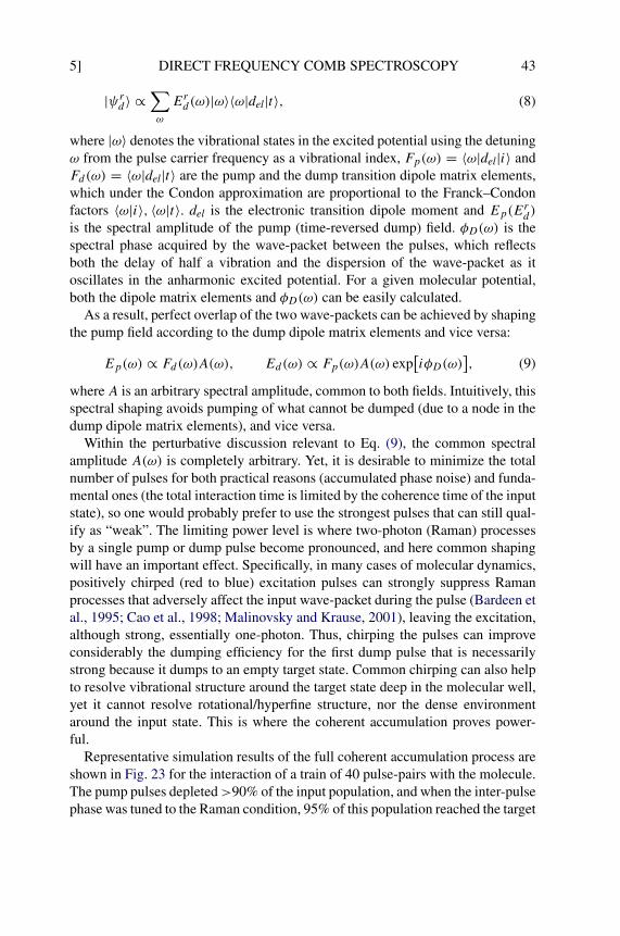
5] DIRECT FREQUENCY COMB SPECTROSCOPY 43
(8)|ψrd 〉 ∝∑ω
Erd(ω)|ω〉〈ω|del|t〉,
where |ω〉 denotes the vibrational states in the excited potential using the detuningω from the pulse carrier frequency as a vibrational index, Fp(ω) = 〈ω|del|i〉 andFd(ω) = 〈ω|del|t〉 are the pump and the dump transition dipole matrix elements,which under the Condon approximation are proportional to the Franck–Condonfactors 〈ω|i〉, 〈ω|t〉. del is the electronic transition dipole moment and Ep(Erd)is the spectral amplitude of the pump (time-reversed dump) field. φD(ω) is thespectral phase acquired by the wave-packet between the pulses, which reflectsboth the delay of half a vibration and the dispersion of the wave-packet as itoscillates in the anharmonic excited potential. For a given molecular potential,both the dipole matrix elements and φD(ω) can be easily calculated.
As a result, perfect overlap of the two wave-packets can be achieved by shapingthe pump field according to the dump dipole matrix elements and vice versa:
(9)Ep(ω) ∝ Fd(ω)A(ω), Ed(ω) ∝ Fp(ω)A(ω) exp[iφD(ω)
],
whereA is an arbitrary spectral amplitude, common to both fields. Intuitively, thisspectral shaping avoids pumping of what cannot be dumped (due to a node in thedump dipole matrix elements), and vice versa.
Within the perturbative discussion relevant to Eq. (9), the common spectralamplitude A(ω) is completely arbitrary. Yet, it is desirable to minimize the totalnumber of pulses for both practical reasons (accumulated phase noise) and funda-mental ones (the total interaction time is limited by the coherence time of the inputstate), so one would probably prefer to use the strongest pulses that can still qual-ify as “weak”. The limiting power level is where two-photon (Raman) processesby a single pump or dump pulse become pronounced, and here common shapingwill have an important effect. Specifically, in many cases of molecular dynamics,positively chirped (red to blue) excitation pulses can strongly suppress Ramanprocesses that adversely affect the input wave-packet during the pulse (Bardeen etal., 1995; Cao et al., 1998; Malinovsky and Krause, 2001), leaving the excitation,although strong, essentially one-photon. Thus, chirping the pulses can improveconsiderably the dumping efficiency for the first dump pulse that is necessarilystrong because it dumps to an empty target state. Common chirping can also helpto resolve vibrational structure around the target state deep in the molecular well,yet it cannot resolve rotational/hyperfine structure, nor the dense environmentaround the input state. This is where the coherent accumulation proves power-ful.
Representative simulation results of the full coherent accumulation process areshown in Fig. 23 for the interaction of a train of 40 pulse-pairs with the molecule.The pump pulses depleted>90% of the input population, and when the inter-pulsephase was tuned to the Raman condition, 95% of this population reached the target
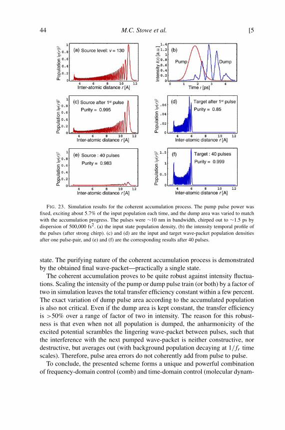
44 M.C. Stowe et al. [5
FIG. 23. Simulation results for the coherent accumulation process. The pump pulse power wasfixed, exciting about 5.7% of the input population each time, and the dump area was varied to matchwith the accumulation progress. The pulses were ∼10 nm in bandwidth, chirped out to ∼1.5 ps bydispersion of 500,000 fs2. (a) the input state population density, (b) the intensity temporal profile ofthe pulses (after strong chirp). (c) and (d) are the input and target wave-packet population densitiesafter one pulse-pair, and (e) and (f) are the corresponding results after 40 pulses.
state. The purifying nature of the coherent accumulation process is demonstratedby the obtained final wave-packet—practically a single state.
The coherent accumulation proves to be quite robust against intensity fluctua-tions. Scaling the intensity of the pump or dump pulse train (or both) by a factor oftwo in simulation leaves the total transfer efficiency constant within a few percent.The exact variation of dump pulse area according to the accumulated populationis also not critical. Even if the dump area is kept constant, the transfer efficiencyis >50% over a range of factor of two in intensity. The reason for this robust-ness is that even when not all population is dumped, the anharmonicity of theexcited potential scrambles the lingering wave-packet between pulses, such thatthe interference with the next pumped wave-packet is neither constructive, nordestructive, but averages out (with background population decaying at 1/fr timescales). Therefore, pulse area errors do not coherently add from pulse to pulse.
To conclude, the presented scheme forms a unique and powerful combinationof frequency-domain control (comb) and time-domain control (molecular dynam-

6] DIRECT FREQUENCY COMB SPECTROSCOPY 45
ics). As such, it enables performance of coherent control tasks with both highefficiency and unprecedented spectral resolution. Due to the use of weak pulsesthe process can be analyzed within a perturbative model, thus opening an ana-lytic path to strong field problems that were so far accessible only by numericaloptimizations.
6. Future Outlook
6.1. ATOMIC CLOCK APPLICATIONS
A general trend throughout the history of precision timekeeping has been to em-ploy oscillators with an ever-increasing frequency, since a clock operating at ahigher frequency provides greater precision through the finer sub-division of aunit of time. Following this trend over the past one hundred years, one finds theadvance from pendulum clocks, to crystal quartz oscillators, to microwave atomicclocks, and now most recently, atomic clocks operating at optical and ultravioletfrequencies (Diddams et al., 2001; Ye et al., 2001). It is likely that this progressionwill continue in the future, and DFCS could play an important role in the push tostill higher frequencies since the high peak powers of the associated femtosecondpulses provide an efficient means to generate coherent radiation at high frequen-cies. Some of the exciting new techniques for producing frequency combs in theextreme ultraviolet regime will be discussed in detail in the following section,but first we present a scheme of employing DFCS to control the frequency combof a femtosecond laser, and thereby produce optical and microwave frequenciesreferenced directly to an atomic transition (Gerginov et al., 2005).
If the optical frequency νn = fo+nfr of a certain comb component can probe,and then be directly stabilized to an atomic transition, the repetition rate instabil-ity will be given by δfr/fr = (1/n)δνn/νn, where δνn/νn is the optical frequencyinstability. In this way, an optical clock is realized without the use of cw lasers.The stability of the optical atomic reference is mapped onto the stability of fr ,which in turn can be measured and used as a frequency reference. Such an ex-periment has been realized by using the setup described in Section 3.2.2. TheF = 3 → F = 2 transition of the Cs D2 line was excited using DFCS and thesubsequent fluorescence was detected. By modulating fr the fluorescence signaland its derivative shown in Fig. 24 were measured. The error signal was then usedto steer fr such that the specific optical mode (n = 352,210) is frequency-lockedto the center of the Fg = 3 – Fe = 2 transition. Now atomically-stabilized, the sta-bility of fr was measured, and a fractional frequency instability plot are shown inFig. 25. The plot shows that instability of better than 10−11 can be easily achievedin 100 s integration time. While this example takes advantage of convenient, yetrelatively broad near-infrared transition in cesium, the basic approach is one thatcould be applied to much higher (and narrower) frequency atomic transitions.
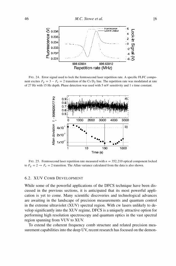
46 M.C. Stowe et al. [6
FIG. 24. Error signal used to lock the femtosecond laser repetition rate. A specific FLFC compo-nent excites Fg = 3 − Fe = 2 transition of the Cs D2 line. The repetition rate was modulated at rateof 27 Hz with 15 Hz depth. Phase detection was used with 5 mV sensitivity and 1 s time constant.
FIG. 25. Femtosecond laser repetition rate measured with n = 352,210 optical component lockedto Fg = 2 → Fe = 2 transition. The Allan variance calculated from the data is also shown.
6.2. XUV COMB DEVELOPMENT
While some of the powerful applications of the DFCS technique have been dis-cussed in the previous sections, it is anticipated that its most powerful appli-cation is yet to come. Many scientific discoveries and technological advancesare awaiting in the landscape of precision measurements and quantum controlin the extreme ultraviolet (XUV) spectral region. With cw lasers unlikely to de-velop significantly into the XUV regime, DFCS is a uniquely attractive option forperforming high resolution spectroscopy and quantum optics in the vast spectralregion spanning from VUV to XUV.
To extend the coherent frequency comb structure and related precision mea-surement capabilities into the deep UV, recent research has focused on the demon-
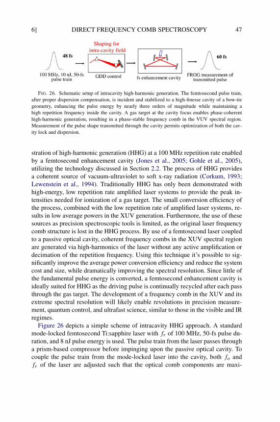
6] DIRECT FREQUENCY COMB SPECTROSCOPY 47
FIG. 26. Schematic setup of intracavity high-harmonic generation. The femtosecond pulse train,after proper dispersion compensation, is incident and stabilized to a high-finesse cavity of a bow-tiegeometry, enhancing the pulse energy by nearly three orders of magnitude while maintaining ahigh repetition frequency inside the cavity. A gas target at the cavity focus enables phase-coherenthigh-harmonic generation, resulting in a phase-stable frequency comb in the VUV spectral region.Measurement of the pulse shape transmitted through the cavity permits optimization of both the cav-ity lock and dispersion.
stration of high-harmonic generation (HHG) at a 100 MHz repetition rate enabledby a femtosecond enhancement cavity (Jones et al., 2005; Gohle et al., 2005),utilizing the technology discussed in Section 2.2. The process of HHG providesa coherent source of vacuum-ultraviolet to soft x-ray radiation (Corkum, 1993;Lewenstein et al., 1994). Traditionally HHG has only been demonstrated withhigh-energy, low repetition rate amplified laser systems to provide the peak in-tensities needed for ionization of a gas target. The small conversion efficiency ofthe process, combined with the low repetition rate of amplified laser systems, re-sults in low average powers in the XUV generation. Furthermore, the use of thesesources as precision spectroscopic tools is limited, as the original laser frequencycomb structure is lost in the HHG process. By use of a femtosecond laser coupledto a passive optical cavity, coherent frequency combs in the XUV spectral regionare generated via high-harmonics of the laser without any active amplification ordecimation of the repetition frequency. Using this technique it’s possible to sig-nificantly improve the average power conversion efficiency and reduce the systemcost and size, while dramatically improving the spectral resolution. Since little ofthe fundamental pulse energy is converted, a femtosecond enhancement cavity isideally suited for HHG as the driving pulse is continually recycled after each passthrough the gas target. The development of a frequency comb in the XUV and itsextreme spectral resolution will likely enable revolutions in precision measure-ment, quantum control, and ultrafast science, similar to those in the visible and IRregimes.
Figure 26 depicts a simple scheme of intracavity HHG approach. A standardmode-locked femtosecond Ti:sapphire laser with fr of 100 MHz, 50-fs pulse du-ration, and 8 nJ pulse energy is used. The pulse train from the laser passes througha prism-based compressor before impinging upon the passive optical cavity. Tocouple the pulse train from the mode-locked laser into the cavity, both fo andfr of the laser are adjusted such that the optical comb components are maxi-
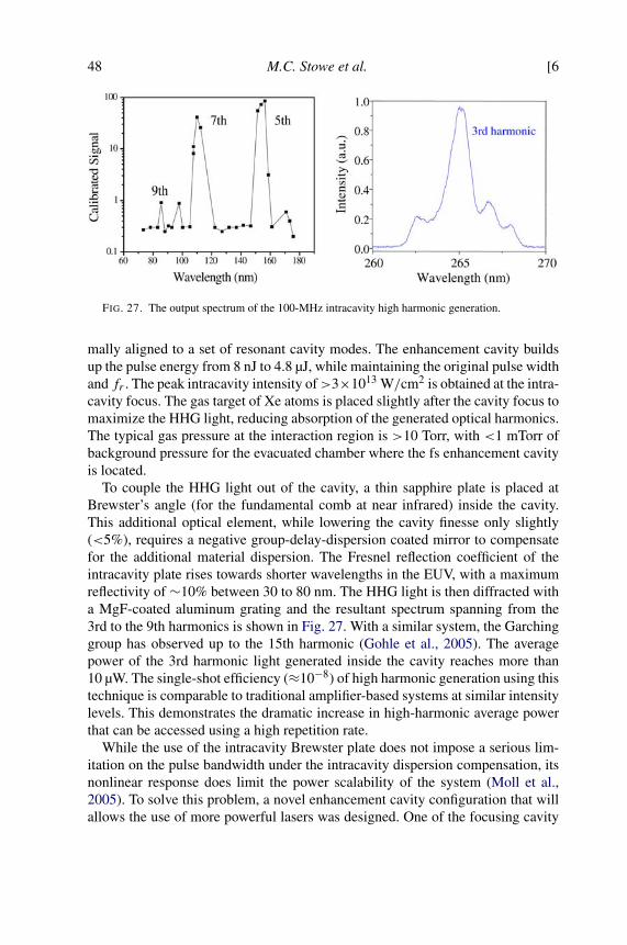
48 M.C. Stowe et al. [6
FIG. 27. The output spectrum of the 100-MHz intracavity high harmonic generation.
mally aligned to a set of resonant cavity modes. The enhancement cavity buildsup the pulse energy from 8 nJ to 4.8 µJ, while maintaining the original pulse widthand fr . The peak intracavity intensity of>3×10¹³ W/cm2 is obtained at the intra-cavity focus. The gas target of Xe atoms is placed slightly after the cavity focus tomaximize the HHG light, reducing absorption of the generated optical harmonics.The typical gas pressure at the interaction region is >10 Torr, with <1 mTorr ofbackground pressure for the evacuated chamber where the fs enhancement cavityis located.
To couple the HHG light out of the cavity, a thin sapphire plate is placed atBrewster’s angle (for the fundamental comb at near infrared) inside the cavity.This additional optical element, while lowering the cavity finesse only slightly(<5%), requires a negative group-delay-dispersion coated mirror to compensatefor the additional material dispersion. The Fresnel reflection coefficient of theintracavity plate rises towards shorter wavelengths in the EUV, with a maximumreflectivity of ∼10% between 30 to 80 nm. The HHG light is then diffracted witha MgF-coated aluminum grating and the resultant spectrum spanning from the3rd to the 9th harmonics is shown in Fig. 27. With a similar system, the Garchinggroup has observed up to the 15th harmonic (Gohle et al., 2005). The averagepower of the 3rd harmonic light generated inside the cavity reaches more than10 µW. The single-shot efficiency (≈10−8) of high harmonic generation using thistechnique is comparable to traditional amplifier-based systems at similar intensitylevels. This demonstrates the dramatic increase in high-harmonic average powerthat can be accessed using a high repetition rate.
While the use of the intracavity Brewster plate does not impose a serious lim-itation on the pulse bandwidth under the intracavity dispersion compensation, itsnonlinear response does limit the power scalability of the system (Moll et al.,2005). To solve this problem, a novel enhancement cavity configuration that willallows the use of more powerful lasers was designed. One of the focusing cavity
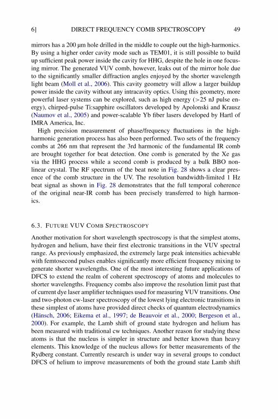
6] DIRECT FREQUENCY COMB SPECTROSCOPY 49
mirrors has a 200 µm hole drilled in the middle to couple out the high-harmonics.By using a higher order cavity mode such as TEM01, it is still possible to buildup sufficient peak power inside the cavity for HHG, despite the hole in one focus-ing mirror. The generated VUV comb, however, leaks out of the mirror hole dueto the significantly smaller diffraction angles enjoyed by the shorter wavelengthlight beam (Moll et al., 2006). This cavity geometry will allow a larger builduppower inside the cavity without any intracavity optics. Using this geometry, morepowerful laser systems can be explored, such as high energy (>25 nJ pulse en-ergy), chirped-pulse Ti:sapphire oscillators developed by Apolonski and Krausz(Naumov et al., 2005) and power-scalable Yb fiber lasers developed by Hartl ofIMRA America, Inc.
High precision measurement of phase/frequency fluctuations in the high-harmonic generation process has also been performed. Two sets of the frequencycombs at 266 nm that represent the 3rd harmonic of the fundamental IR combare brought together for beat detection. One comb is generated by the Xe gasvia the HHG process while a second comb is produced by a bulk BBO non-linear crystal. The RF spectrum of the beat note in Fig. 28 shows a clear pres-ence of the comb structure in the UV. The resolution bandwidth-limited 1 Hzbeat signal as shown in Fig. 28 demonstrates that the full temporal coherenceof the original near-IR comb has been precisely transferred to high harmon-ics.
6.3. FUTURE VUV COMB SPECTROSCOPY
Another motivation for short wavelength spectroscopy is that the simplest atoms,hydrogen and helium, have their first electronic transitions in the VUV spectralrange. As previously emphasized, the extremely large peak intensities achievablewith femtosecond pulses enables significantly more efficient frequency mixing togenerate shorter wavelengths. One of the most interesting future applications ofDFCS to extend the realm of coherent spectroscopy of atoms and molecules toshorter wavelengths. Frequency combs also improve the resolution limit past thatof current dye laser amplifier techniques used for measuring VUV transitions. Oneand two-photon cw-laser spectroscopy of the lowest lying electronic transitions inthese simplest of atoms have provided direct checks of quantum electrodynamics(Hänsch, 2006; Eikema et al., 1997; de Beauvoir et al., 2000; Bergeson et al.,2000). For example, the Lamb shift of ground state hydrogen and helium hasbeen measured with traditional cw techniques. Another reason for studying theseatoms is that the nucleus is simpler in structure and better known than heavyelements. This knowledge of the nucleus allows for better measurements of theRydberg constant. Currently research is under way in several groups to conductDFCS of helium to improve measurements of both the ground state Lamb shift
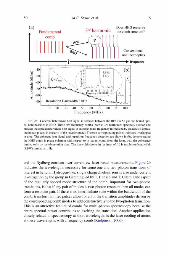
50 M.C. Stowe et al. [6
FIG. 28. Coherent heterodyne beat signal is detected between the HHG in Xe gas and bound opti-cal nonlinearities in BBO. These two frequency combs (both at 3rd harmonic) spectrally overlap andprovide the optical heterodyne beat signal at an offset radio frequency introduced by an acousto-opticalmodulator placed in one arm of the interferometer. The two corresponding pulses trains are overlappedin time. The coherent beat signal and repetition frequency detection are shown in (b), demonstratingthe HHG comb is phase coherent with respect to its parent comb from the laser, with the coherencelimited only by the observation time. The linewidth shown in the inset of (b) is resolution bandwidth(RBW) limited at 1 Hz.
and the Rydberg constant over current cw-laser based measurements. Figure 29indicates the wavelengths necessary for some one and two-photon transitions ofinterest in helium. Hydrogen-like, singly charged helium ions is also under currentinvestigation by the group in Garching led by T. Hänsch and T. Udem. One aspectof the regularly spaced mode structure of the comb, important for two-photontransitions, is that if any pair of modes is two-photon resonant then all modes canform a resonant pair. If there is no intermediate state within the bandwidth of thecomb, transform limited pulses allow for all of the transition amplitudes driven bythe corresponding comb modes to add constructively to the two-photon transition.This is an attractive feature of combs for multi-photon spectroscopy because theentire spectral power contributes to exciting the transition. Another applicationclosely related to spectroscopy at short wavelengths is the laser cooling of atomsat these wavelengths with a frequency comb (Kielpinski, 2006).
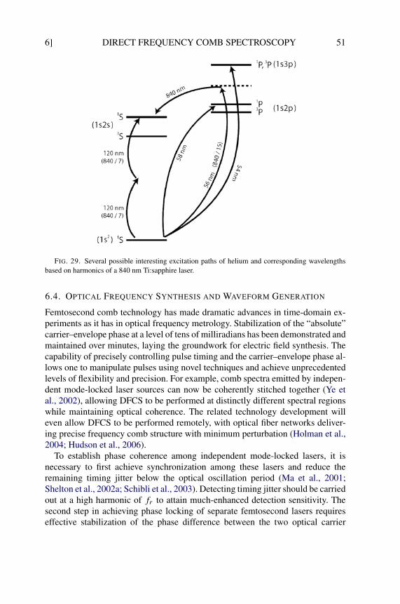
6] DIRECT FREQUENCY COMB SPECTROSCOPY 51
FIG. 29. Several possible interesting excitation paths of helium and corresponding wavelengthsbased on harmonics of a 840 nm Ti:sapphire laser.
6.4. OPTICAL FREQUENCY SYNTHESIS AND WAVEFORM GENERATION
Femtosecond comb technology has made dramatic advances in time-domain ex-periments as it has in optical frequency metrology. Stabilization of the “absolute”carrier–envelope phase at a level of tens of milliradians has been demonstrated andmaintained over minutes, laying the groundwork for electric field synthesis. Thecapability of precisely controlling pulse timing and the carrier–envelope phase al-lows one to manipulate pulses using novel techniques and achieve unprecedentedlevels of flexibility and precision. For example, comb spectra emitted by indepen-dent mode-locked laser sources can now be coherently stitched together (Ye etal., 2002), allowing DFCS to be performed at distinctly different spectral regionswhile maintaining optical coherence. The related technology development willeven allow DFCS to be performed remotely, with optical fiber networks deliver-ing precise frequency comb structure with minimum perturbation (Holman et al.,2004; Hudson et al., 2006).
To establish phase coherence among independent mode-locked lasers, it isnecessary to first achieve synchronization among these lasers and reduce theremaining timing jitter below the optical oscillation period (Ma et al., 2001;Shelton et al., 2002a; Schibli et al., 2003). Detecting timing jitter should be carriedout at a high harmonic of fr to attain much-enhanced detection sensitivity. Thesecond step in achieving phase locking of separate femtosecond lasers requireseffective stabilization of the phase difference between the two optical carrier

52 M.C. Stowe et al. [8
waves (Shelton et al., 2001, 2002b; Holman et al., 2003b; Bartels et al., 2004b;Kobayashi et al., 2005). Phase locking demands that the spectral combs of indi-vidual lasers be maintained exactly coincident in the region of spectral overlapso that the two sets of combs form a continuous and phase-coherent entity. A co-herent heterodyne-beat signal between the frequency combs can be used to yieldinformation about the difference in the offset frequencies, which can then be con-trolled, resulting in two pulse trains with nearly identical phase evolution.
Phase-coherent femtosecond combs have been extended to the mid-infraredspectral region (Foreman et al., 2003, 2005; Zimmermann et al., 2004). Being ableto combine the characteristics of two or more pulsed lasers working at differentwavelengths provides a flexible approach to coherent control and it is particu-larly important for difficult to reach spectral regions. Two independent, pulse-synchronized, and phase-locked mode-locked Ti:sapphire lasers can be used ina difference-frequency generation (DFG) experiment to produce phase coherentfrequency combs in the mid-IR region, with the wavelength spanning a few totens of microns. The capability of expanding the spectral coverage of frequencycombs while maintain phase coherence is an important ingredient for the goal ofoptical arbitrary waveform synthesizer. The other important component is precisespectral shaping, including both amplitude and phase. Indeed, an optical arbitrarywaveform synthesizer will be the ultimate tool for DFCS, permitting precisionspectroscopy and high-resolution quantum control of matter across a vast rangeof energy scale.
7. Concluding Remarks
Once wide-bandwidth, precisely stabilized optical frequency combs becameavailable in laboratories, direct frequency comb spectroscopy has made rapidprogress and found many different applications. Its future impact remains promis-ing for a number of scientific and technological fields, including precision spec-troscopy, high-resolution quantum control, arbitrary optical waveform synthesis,long-distance communications, and extreme nonlinear physics. Development offrequency combs at various spectral regions, with the capability of controllingboth the time-domain coherence and spectral-domain phase, will no doubt makeDFCS an attractive tool to study many atomic, molecular, and condensed mattersystems.
8. Acknowledgements
We sincerely thank many of our colleagues and coworkers who have made criticalcontributions to the work reported in this review. In particular, R.J. Jones led the
9] DIRECT FREQUENCY COMB SPECTROSCOPY 53
initial effort and, along with K.D. Moll, T.R. Schibli, D. Yost, and D. Hudson, car-ried out a large portion of the femtosecond enhancement cavity work. A. Marian,D. Felinto, and J. Lawall are important contributors to the initial development ofbroadband DFCS work. A. Bartels, T. Fortier, L. Hollberg, Y. Le Coq, V. Mbele,C. Oates, D. Ortega, and C. Tanner are acknowledged for their invaluable con-tributions to the Ca and Cs spectroscopy, and the VIPA-based spectrometer. Webenefited from useful discussions with E. Eyler, J.L. Hall, S.T. Cundiff, F. Cruzand A. Weiner. Low-loss, low-dispersion, and wide-bandwidth mirrors are pro-vided by R. Lalezari of Advanced Thin Films. We also thank A. Fernandez,A. Apolonski, F. Krausz, I. Hartl, and M. Fermann for providing high energyfemtosecond oscillators. Finally, we gratefully acknowledge funding support fromNIST, AFOSR, ONR, NSF, and NASA. A. Pe’er thanks the Fulbright foundationfor financial support. J.E. Stalnaker gratefully acknowledges the support of theNational Research Council. Finally, we thank T. Schibli and T. Fortier for theirmany useful comments on the manuscript.
9. References
Anderson, D.Z., Frisch, J.C., Masser, C.S. (1984). Mirror reflectometer based on optical cavity decaytime. Appl. Opt. 23, 1238–1245.
Apolonski, A., Poppe, A., Tempea, G., Spielmann, C., Udem, T., Holzwarth, R., Hänsch, T.W., Krausz,F. (2000). Controlling the phase evolution of few-cycle light pulses. Phys. Rev. Lett. 85, 740–743.
Arissian, L., Diels, J.-C. (2006). Repetition rate spectroscopy of the dark line resonance in Rubidium.Opt. Comm. 264, 169–173.
Aumiler, D., Ban, T., Skenderovic, H., Pichler, G. (2005). Velocity selective optical pumping of Rbhyperfine lines induced by a train of femtosecond pulses. Phys. Rev. Lett. 95. 233001.
Baklanov, Y.V., Chebotayev, V.P. (1977). Narrow resonances of two-photon absorption of super-narrow pulses in a gas. Appl. Phys. 12, 97–99.
Balling, P., Maas, D.J., Noordam, L.D. (1994). Interference in climbing a quantum ladder system withfrequency-chirped pulses. Phys. Rev. A 50, 4276–4285.
Ban, T., Aumiler, D., Skenderovic, H., Pichler, G. (2006). Mapping of the optical frequency comb tothe atom-velocity comb. Phys. Rev. A 73. 043407-1-10.
Baltuska, A., Udem, T., Uiberacker, M., Hentschel, M., Goulielmakis, E., Gohle, C., Holzwarth, R.,Yakovlev, V.S., Scrinzi, A., Hänsch, T.W., Krausz, F. (2003). Attosecond control of electronicprocesses by intense light fields. Nature 421, 611–615.
Bardeen, C.J., Wang, Q., Shank, C.V. (1995). Selective excitation of vibrational wave-packet motionusing chirped pulses. Phys. Rev. Lett. 75, 3410–3413.
Bartels, A., Oates, C.W., Hollberg, L., Diddams, S.A. (2004a). Stabilization of femtosecond laserfrequency combs with subhertz residual linewidths. Opt. Lett. 29, 1081–1083.
Bartels, A., Newbury, N.R., Thomann, I., Hollberg, L., Diddams, S.A. (2004b). Broadband phase-coherent optical frequency synthesis with actively linked Ti:sapphire and Cr:forsterite femtosec-ond lasers. Opt. Lett. 29, 403–405.
Bergeson, S.D., Baldwin, K.G.H., Lucatorto, T.B., McIlrath, T.J., Cheng, C.H., Eyler, E.E. (2000).Doppler-free two-photon spectroscopy in the vacuum ultraviolet: Helium 11S–21S transition.J. Opt. Soc. Am. B 17, 1599–1606.
54 M.C. Stowe et al. [9
Bordé, C.J., Salomon, Ch., Avrillier, S., Van Lerberghe, A., Bréant, Ch., Bassi, D., Scoles, G. (1984).Optical Ramsey fringes with traveling waves. Phys. Rev. A 30, 1836–1848.
Boyd, M.M., Zelevinsky, T., Ludlow, A.D., Foreman, S.M., Blatt, S., Ido, T., Ye, J. (2006). Opticalatomic coherence at the 1-second time scale. Science 314, 1430–1433.
Brattke, S., Kallmann, U., Hartmann, W.-D. (1998). Coherent dark states of Rubidium 87 in a buffergas using pulsed laser light. Eur. Phys. J. D 3, 159–161.
Cao, J., Bardeen, C.J., Wilson, K.R. (1998). Molecular “π pulse” for total inversion of electronic statepopulation. Phys. Rev. Lett. 80, 1406–1409.
Casperson, L.W. (1998). Few-cycle pulses in two-level media. Phys. Rev. A 57, 609–621.Chatel, B., Degert, J., Stock, S., Girard, B. (2003). Competition between sequential and direct paths
in a two-photon transition. Phys. Rev. A 68. 041402-1-4.Chatel, B., Degert, J., Girard, B. (2004). Role of quadratic and cubic spectral phases in ladder climbing
with ultrashort pulses. Phys. Rev. A 70. 053414-1-10.Chen, L.-S., Ye, J. (2003). Extensive, high-resolution measurement of hyperfine interactions: Precise
investigations of molecular potentials and wave functions. Chem. Phys. Lett. 381, 777–783.Chen, L.-S., Cheng, W.Y., Ye, J. (2004). Hyperfine interactions and perturbation effects in the
B0+u (3�u) state of 127I2. J. Opt. Soc. Am. B 21, 820–832.
Chen, L.-S., de Jong, W.A., Ye, J. (2005). Characterization of the molecular iodine electronic wavefunctions and potential energy curves through hyperfine interactions in B0+
u (3�u) state. J. Opt.Soc. Am. B 22, 951–961.
Corkum, P.B. (1993). Plasma perspective on strong-field multiphoton ionization. Phys. Rev. Lett. 71,1994–1997.
Couillaud, B., Ducasse, A., Sarger, L., Boscher, D. (1980). High-resolution saturated absorption spec-troscopy with coherent trains of short light pulses. Appl. Phys. Lett. 36, 407–409.
Crosson, E.R., Haar, P., Marcus, G.A., Schwettman, H.A., Paldus, B.A., Spence, T.G., Zare, R.N.(1999). Pulse-stacked cavity ring-down spectroscopy. Rev. Sci. Instrum. 70, 4–10.
Cruz, F.C., Stowe, M.C., Ye, J. (2006). Tapered semiconductor amplifiers for optical frequency combsin the near infrared. Opt. Lett. 31, 1337–1339.
Cundiff, S.T., Ye, J. (2003). Colloquium: Femtosecond optical frequency combs. Rev. Mod. Phys. 75,325–342.
Cundiff, S.T., Ye, J., Hall, J.L. (2001). Optical frequency synthesis based on mode-locked lasers. Rev.Sci. Instrum. 72, 3749–3771.
de Beauvoir, B., Schwob, C., Acef, O., Jozefowski, L., Hilico, L., Nez, F., Julien, L., Clairon, A.,Biraben, F. (2000). Metrology of the hydrogen and deuterium atoms: Determination of the Ryd-berg constant and Lamb shifts. Eur. Phys. J. D 12, 61–93.
Degenhardt, C., Stoeher, H., Lisdat, C., Wilpers, G., Schnatz, H., Lipphardt, B., Nazarova, T., Pottie,P.-E., Sterr, U., Helmcke, J., Riehle, F. (2005). Calcium optical frequency standard with ultracoldatoms: Approaching 10−15 relative uncertainty. Phys. Rev. A 72. 62111-1-7.
Delagnes, J.C., Blanchet, V., Bouchene, M.A. (2003). Role of the radiated field in the propagation ofan ultra-short chirped pulse. Opt. Comm. 227, 125–131.
Diddams, S.A., Diels, J.-C., Atherton, B.W. (1998). Differential intracavity phase spectroscopy andits application to a three-level system in samarium. Phys. Rev. A 58, 2252–2264.
Diddams, S.A., Jones, D.J., Ye, J., Cundiff, S.T., Hall, J.L., Ranka, J.K., Windeler, R.S., Holzwarth,R., Udem, T., Hänsch, T.W. (2000). Direct link between microwave and optical frequencies with a300 THz femtosecond laser comb. Phys. Rev. Lett. 84, 5102–5105.
Diddams, S.A., Udem, T., Bergquist, J.C., Curtis, E.A., Drullinger, R.E., Hollberg, L., Itano, W.M.,Lee, W.D., Oates, C.W., Vogel, K.R., Wineland, D.J. (2001). An optical clock based on a singletrapped 199Hg+ ion. Science 293, 825–828.
Diddams, S., Hollberg, L., Mbele, V. (2006). High-resolution spectral fingerprinting with a stabilizedfemtosecond laser frequency comb. In: 15th International Conference on Ultrafast Phenomena,Technical Digest (CD). Optical Society of America. Paper WA3.
9] DIRECT FREQUENCY COMB SPECTROSCOPY 55
Diddams, S., Hollberg, L., Mbele, V. (2007). Molecular fingerprinting with the resolved modes of afemtosecond laser frequency comb. Nature 445, 627–630.
Drever, R.W.P., Hall, J.L., Kowalski, F.V., Hough, J., Ford, G.M., Munley, A.J., Ward, H. (1983).Laser phase and frequency stabilization using an optical resonator. Appl. Phys. B 31, 97–105.
Dudley, J.M., Genty, G., Coen, S. (2006). Supercontinuum generation in photonic crystal fiber. Rev.Mod. Phys. 78, 1135–1184.
Dudovich, N., Polack, T., Pe’er, A., Silberberg, Y. (2005). Simple route to strong field control. Phys.Rev. Lett. 94. 083002-1-4.
Eckstein, J.N., Ferguson, A.I., Hänsch, T.W. (1978). High-resolution 2-photon spectroscopy with pi-cosecond light-pulses. Phys. Rev. Lett. 40, 847–850.
Eikema, K.S.E., Ubachs, W., Vassen, W., Hogervorst, W. (1997). Lamb shift measurement in the 1 S1ground state of Helium. Phys. Rev. A 55, 1866–1884.
Ell, R., Morgner, U., Kartner, F.X., Fujimoto, J.G., Ippen, E.P., Scheuer, V., Angelow, G., Tschudi, T.,Lederer, M.J., Boiko, A., Luther-Davies, B. (2001). Generation of 5-fs pulses and octave-spanningspectra directly from a Ti:sapphire laser. Opt. Lett. 26, 373–375.
Felinto, D., Acioli, L.H., Vianna, S.S. (2004). Accumulative effects in the coherence of three-levelatoms excited by femtosecond-laser frequency combs. Phys. Rev. A 70. 043403-1-10.
Ferguson, A.I., Eckstein, J.N., Hänsch, T.W. (1979). Polarization spectroscopy with ultrashort lightpulses. Appl. Phys. 18, 257–260.
Foreman, S.M., Jones, D.J., Ye, J. (2003). Flexible and rapidly configurable femtosecond pulse gen-eration in the mid-IR. Opt. Lett. 28, 370–372.
Foreman, S.M., Marian, A., Ye, J., Petrukhin, E.A., Gubin, M.A., Mücke, O.D., Wong, F.N.C., Ippen,E.P., Kärtner, F.X. (2005). Demonstration of a HeNe/CH4-based optical molecular clock. Opt.Lett. 30, 570–572.
Foreman, S.M., Holman, K.W., Hudson, D.D., Jones, D.J., Ye, J. (2007). Remote transfer of ultrastablefrequency references via fiber networks. Rev. Sci. Instrum. 78. 021101-1-25.
Fortier, T.M., Jones, D.J., Cundiff, S.T. (2003). Phase stabilization of an octave-spanning Ti:sapphirelaser. Opt. Lett. 28, 2198–2200.
Fortier, T.M., Bartels, A., Diddams, S.A. (2006a). Octave-spanning Ti:sapphire laser with a repetitionrate >1 GHz for optical frequency measurements and comparisons. Opt. Lett. 31, 1011–1013.
Fortier, T.M., Le Coq, Y., Stalnaker, J.E., Ortega, D., Diddams, S.A., Oates, C.W., Hollberg, L.(2006b). Kilohertz-resolution spectroscopy of cold atoms with an optical frequency comb. Phys.Rev. Lett. 97. 163905-1-4.
Fukuda, Y., Hayashi, J., Kondo, K., Hashi, T. (1981). Synchronized quantum beat spectroscopy usingperiodic impact excitations with CW mode-locked laser pulses. Opt. Comm. 38, 357–360.
Garraway, B.M., Suominen, K. (1995). Wave-packet dynamics: new physics and chemistry in femto-time. Rep. Prog. Phys. 58, 365–419.
Gaubatz, U., Rudecki, P., Schiemann, S., Bergmann, K. (1990). Population transfer between molecularvibrational levels by stimulated Raman scattering with partially overlapping laser fields. A newconcept and experimental results. J. Chem. Phys. 92, 5363–5376.
Genkin, G.M. (1998). Rabi frequency and nonlinearity of a two-level atom for an ultrashort opticalpulse. Phys. Rev. A 58, 758–760.
Gerginov, V., Tanner, C.E., Diddams, S., Bartels, A., Hollberg, L. (2004). Optical frequency mea-surements of 6s 2S1/2 → 6p 2P3/2 transition in a 133Cs atomic beam using a femtosecond laserfrequency comb. Phys. Rev. A 70. 42505-1-8.
Gerginov, V., Tanner, C.E., Diddams, S.A., Bartels, A., Hollberg, L. (2005). High-resolution spec-troscopy with a femtosecond laser frequency comb. Opt. Lett. 30, 1734–1736.
Gerginov, V., Calkins, K., Tanner, C.E., McFerran, J.J., Diddams, S., Bartels, A., Hollberg, L. (2006).Optical frequency measurements of 6s 2S1/2 → 6p 2P1/2(D1) transitions in 133Cs and their im-pact on the fine-structure constant. Phys. Rev. A 73. 32504-1-10.
56 M.C. Stowe et al. [9
Gherman, T., Eslami, E., Romanini, D., Kassi, S., Vial, J.-C., Sadeghi, N. (2004). High sensitivitybroad-band mode-locked cavity-enhanced absorption spectroscopy: Measurement of Ar∗(3P2)
atom and N+2 ion densities. J. Phys. D 37, 2408–2415.
Gohle, C., Udem, T., Herrmann, M., Rauschenberger, J., Holzwarth, R., Schuessler, H.A., Krausz, F.,Hänsch, T.W. (2005). A frequency comb in the extreme ultraviolet. Nature 436, 234–237.
Greenland, P.T. (1983). Resonances excited by a train of delta function pulses. J. Phys. B: At. Mol.Phys. 16, 2515–2521.
Hall, J.L. (2006). Nobel lecture: Defining and measuring optical frequencies. Rev. Mod. Phys. 78,1279–1295.
Hall, J.L., Bordé, C.J., Uehara, K. (1976). Direct optical resolution of the recoil effect using saturatedabsorption spectroscopy. Phys. Rev. Lett. 37, 1339–1342.
Halzwarth, R., Nevsky, A.Yu., Zimmermann, M., Udem, Th., Hänsch, T.W., Von Zanthier, J., Walther,H., Knight, J.C., Wadsworth, W.J., Russell, P.St.J., Skvortsov, M.N., Bagayev, S.N. (2001). Ab-solute frequency measurement of iodine lines with a femtosecond optical synthesizer. Appl. Phys.B 73, 269–271.
Hänsch, T.W. (2006). Nobel lecture: Passion for precision. Rev. Mod. Phys. 78, 1297–1309.Hänsch, T.W., Wong, N.C. (1980). Two-photon spectroscopy with an FM laser. Metrologia 16, 101–
104.Harde, H., Burggraf, H. (1982). Ultrahigh-resolution coherence spectroscopy by means of periodic
excitation with picosecond pulses. Opt. Comm. 40, 441–445.Heavner, T.P., Jefferts, S.R., Donley, E.A., Shirley, J.H., Parker, T.E. (2005). NIST-F1: Recent evalu-
ations and accuracy improvements. Metrologia 42, 411–422.Holman, K.W., Jones, R.J., Marian, A., Cundiff, S.T., Ye, J. (2003a). Intensity-related dynamics of
femtosecond frequency combs. Opt. Lett. 28, 851–853.Holman, K.W., Jones, D.J., Ye, J., Ippen, E.P. (2003b). Orthogonal control of the frequency comb
dynamics of a mode-locked laser diode. Opt. Lett. 28, 2405–2407.Holman, K.W., Jones, D.J., Hudson, D.D., Ye, J. (2004). Precise frequency transfer through a fiber
network by use of 1.5 µm mode-locked sources. Opt. Lett. 29, 1554–1556.Hudson, D.D., Foreman, S.M., Cundiff, S.T., Ye, J. (2006). Synchronization of mode-locked fem-
tosecond lasers through a fiber link. Opt. Lett. 31, 1951–1953.Jenkins, F.A., White, H.E. (1976). “Fundamentals of Optics”, 4th edition. McGraw Hill, New York.Jonas, D.M. (2003). Two-dimensional femtosecond spectroscopy. Annual Rev. Phys. Chem. 54, 425–
463.Jones, R.J., Diels, J.-C. (2001). Stabilization of femtosecond lasers for optical frequency metrology
and direct optical to radio frequency synthesis. Phys. Rev. Lett. 86, 3288–3291.Jones, R.J., Ye, J. (2002). Femtosecond pulse amplification by coherent addition in a passive optical
cavity. Opt. Lett. 27, 1848–1850.Jones, R.J., Ye, J. (2004). High-repetition-rate coherent femtosecond pulse amplification with an ex-
ternal passive optical cavity. Opt. Lett. 29, 2812–2814.Jones, D.J., Diddams, S.A., Ranka, J.K., Stentz, A., Windeler, R.S., Hall, J.L., Cundiff, S.T. (2000).
Carrier–envelope phase control of femtosecond mode-locked lasers and direct optical frequencysynthesis. Science 288, 635–639.
Jones, R.J., Thomann, I., Ye, J. (2004). Precision stabilization of femtosecond lasers to high-finesseoptical cavities. Phys. Rev. A 69. 051803-1-4.
Jones, R.J., Moll, K.D., Thorpe, M.J., Ye, J. (2005). Phase-coherent frequency combs in the vacuumultraviolet via high-harmonic generation inside a femtosecond enhancement cavity. Phys. Rev.Lett. 94. 193201-1-4.
Kielpinski, D. (2006). Laser cooling of atoms and molecules with ultrafast pulses. Phys. Rev. A 73.063407-1-6.
Kobayashi, Y., Yoshitomi, D., Kakehata, M., Takada, H., Torizuka, K. (2005). Long-term optical phaselocking between femtosecond Ti:sapphire and Cr:forsterite lasers. Opt. Lett. 30, 2496–2498.
9] DIRECT FREQUENCY COMB SPECTROSCOPY 57
Lee, K.F., Villeneuve, D.M., Corkum, P.B., Shapiro, E.A. (2004). Phase control of rotational wavepackets and quantum information. Phys. Rev. Lett. 93. 233601-1-4.
Lewenstein, M., Balcou, P., Ivanov, M.Y., Lhuillier, A., Corkum, P.B. (1994). Theory of high-harmonic generation by low-frequency laser fields. Phys. Rev. A 49, 2117–2132.
Ludlow, A.D., Boyd, M.M., Zelevinsky, T., Foreman, S.M., Blatt, S., Notcutt, M., Ido, T., Ye, J.(2006). Systematic study of the 87Sr clock transition in an optical lattice. Phys. Rev. Lett. 96.033003-1-4.
Ma, L.S., Shelton, R.K., Kapteyn, H.C., Murnane, M.M., Ye, J. (2001). Sub-10-femtosecond activesynchronization of two passively mode-locked Ti:sapphire oscillators. Phys. Rev. A 64. 021802-1-4.
Ma, L.-S., Zucco, M., Picard, S., Robertsson, L., Windeler, R.S. (2003). A new method to determinethe absolute mode number of a mode-locked femtosecond-laser comb used for absolute opticalfrequency measurements. IEEE Journal of Selected Topics in Quantum Electronics 9, 1066–1071.
Malinovsky, V.S., Krause, J.L. (2001). Efficiency and robustness of coherent population transfer withintense, chirped laser pulses. Phys. Rev. A 63. 043415-1-8.
Marian, A., Stowe, M.C., Lawall, J.R., Felinto, D., Ye, J. (2004). United time-frequency spectroscopyfor dynamics and global structure. Science 306, 2063–2068.
Marian, A., Stowe, M.C., Felinto, D., Ye, J. (2005). Direct frequency comb measurements of absoluteoptical frequencies and population transfer dynamics. Phys. Rev. Lett. 95. 023001-1-4.
Mbele, V., Stalnaker, J.E., Gerginov, V., Diddams, S.A., Tanner, C.E., Hollberg, L. (in preparation).Meshulach, D., Silberberg, Y. (1998). Coherent quantum control of two-photon transitions by a fem-
tosecond laser pulse. Nature 396, 239–242.Minoshima, K., Matsumoto, H. (2000). High-accuracy measurement of 240-m distance in an optical
tunnel by use of a compact femtosecond laser. Appl. Opt. 39, 5512–5517.Mlynek, J., Lange, W., Harde, H., Burggraf, H. (1981). High-resolution coherence spectroscopy using
pulse trains. Phys. Rev. A 24, 1099–1102.Moll, K.D., Jones, R.J., Ye, J. (2005). Nonlinear dynamics inside femtosecond enhancement cavities.
Opt. Express 13, 1672–1678.Moll, K.D., Jones, R.J., Ye, J. (2006). Output coupling methods for cavity-based high-harmonic gen-
eration. Opt. Express 14, 8189–8197.Morgner, U., Ell, R., Metzler, G., Schibli, T.R., Kärtner, F.X., Fujimoto, J.G., Haus, H.A., Ippen,
E.P. (2001). Nonlinear optics with phase-controlled pulses in the sub-two-cycle regime. Phys. Rev.Lett. 86, 5462–5465.
Mücke, O.D., Ell, R., Winter, A., Kim, J.W., Birge, J.R., Matos, L., Kartner, F.X. (2005). Self-referenced 200 MHz octave-spanning Ti:sapphire laser with 50 attosecond carrier–envelope phasejitter. Opt. Exp. 13, 5163–5169.
Naumov, S., Fernandez, A., Graf, R., Dombi, P., Krausz, F., Apolonski, A. (2005). Approaching themicrojoule frontier with femtosecond laser oscillators. New J. Phys. 7, 216.
Oates, C.W., Curtis, E.A., Hollberg, L. (2000). Improved short-term stability of optical frequencystandards: Approaching 1 Hz in 1 s with the Ca standard at 657 nm. Opt. Lett. 25, 1603–1605.
Oates, C.W., Wilpers, G., Hollberg, L. (2005). Observation of large atomic-recoil-induced asymme-tries in cold atom spectroscopy. Phys. Rev. A 71, 23404-1-6.
O’Keefe, A., Deacon, D.A.G. (1988). Cavity ringdown optical spectrometer for absorption-measurements using pulsed laser sources. Rev. Sci. Instrum. 59, 2544–2551.
Paulus, G.G., Grasbon, F., Walther, H., Villoresi, P., Nisoli, M., Stagira, S., Priori, E., De Silvestri,S. (2001). Absolute-phase phenomena in photoionization with few-cycle laser pulses. Nature 414,182–184.
Pe’er, A., Shapiro, E.A., Stowe, M.C., Shapiro, M., Ye, J. (2007). Precise control of molecular dy-namics with a femtosecond frequency comb—A weak field route to strong field coherent control.Phys. Rev. Lett. 98. 113004-1-4.
58 M.C. Stowe et al. [9
Potma, E.O., Jones, D.J., Cheng, J.X., Xie, X.S., Ye, J. (2002). High-sensitivity coherent anti-StokesRaman scattering microscopy with two tightly synchronized picosecond lasers. Opt. Lett. 27,1168–1170.
Potma, E.O., Evans, C., Xie, X.S., Jones, R.J., Ye, J. (2003). High-repetition rate picosecond pulseamplification with an external passive optical cavity. Opt. Lett. 28, 1835–1837.
Potma, E.O., Xie, X.S., Muntean, L., Preusser, J., Jones, D.J., Ye, J., Leone, S.R., Hinsberg, W.D.,Schade, W. (2004). Chemical imaging of photoresists with coherent anti-Stokes Raman scattering(CARS) microscopy. J. Phys. Chem. B 108, 1296–1301.
Rabitz, H., Vivie-Riedle, R., Motzkus, M., Kompa, K. (2000). Whither the future of controlling quan-tum phenomena? Science 288, 824–828.
Ramond, T.M., Diddams, S.A., Hollberg, L. (2002). Phase-coherent link from optical to microwavefrequencies by means of the broadband continuum from a 1-GHz Ti:sapphire femtosecond oscil-lator. Opt. Lett. 27, 1842–1844.
Ranka, J.K., Windeler, R.S., Stentz, A.J. (2000). Visible continuum generation in air-silica microstruc-ture optical fibers with anomalous dispersion at 800 nm. Opt. Lett. 25, 25–27.
Reichert, J., Holzwarth, R., Udem, T., Hänsch, T.W. (1999). Measuring the frequency of light withmode-locked lasers. Opt. Comm. 172, 59–68.
Rice, S.A., Zhao, M. (2000). “Optical Control of Molecular Dynamics”. John Wiley & Sons, NewYork.
Salour, M.M., Cohen-Tannoudji, C. (1977). Observation of Ramsey’s interference fringes in the profileof Doppler-free two-photon resonances. Phys. Rev. Lett. 38, 757–760.
Sautenkov, V.A., Rostovtsev, Y.V., Ye, C.Y., Welch, G.R., Kocharovskaya, O., Scully, M.O. (2005).Electromagnetically induced transparency in rubidium vapor prepared by a comb of short opticalpulses. Phys. Rev. A 71. 063804-1-4.
Scherer, J.J., Paul, J.B., Jiao, H., O’Keefe, A. (2001). Broadband ringdown spectral photography.Appl. Opt. 40, 6725–6732.
Schibli, T.R., Kim, J., Kuzucu, O., Gopinath, J.T., Tandon, S.N., Petrich, G.S., Kolodziejski, L.A.,Fujimoto, J.G., Ippen, E.P., Kärtner, F.X. (2003). Attosecond active synchronization of passivelymode-locked lasers by balanced cross correlation. Opt. Lett. 28, 947–949.
Schliesser, A., Gohle, C., Udem, T., Hänsch, T.W. (2006). Complete characterization of a broadbandhigh-finesse cavity using an optical frequency comb. Opt. Exp. 14, 5975–5983.
Shapiro, M., Brumer, P. (1986). Laser control of product quantum state populations in unimolecularreactions. J. Chem. Phys. 84, 4103–4104.
Shapiro, M., Brumer, P. (2003a). “Principles of the Quantum Control of Molecular Processes”. JohnWiley & Sons, Hoboken.
Shapiro, M., Brumer, P. (2003b). Coherent control of molecular dynamics. Rep. Prog. Phys. 66, 859–942.
Shelton, R.K., Ma, L.S., Kapteyn, H.C., Murnane, M.M., Hall, J.L., Ye, J. (2001). Phase-coherentoptical pulse synthesis from separate femtosecond lasers. Science 293, 1286–1289.
Shelton, R.K., Foreman, S.M., Ma, L.S., Hall, J.L., Kapteyn, H.C., Murnane, M.M., Notcutt, M., Ye,J. (2002a). Subfemtosecond timing jitter between two independent, actively synchronized, mode-locked lasers. Opt. Lett. 27, 312–314.
Shelton, R.K., Ma, L.S., Kapteyn, H.C., Murnane, M.M., Hall, J.L., Ye, J. (2002b). Active syn-chronization and carrier phase locking of two separate mode-locked femtosecond lasers. J. Mod.Opt. 49, 401–409.
Shirasaki, M. (1996). Large angular dispersion by a virtually imaged phased array and its applicationto a wavelength demultiplexer. Opt. Lett. 21, 366–368.
Snadden, M.J., Bell, A.S., Riis, E., Ferguson, A.I. (1996). Two-photon spectroscopy of laser-cooledRb using a mode-locked laser. Opt. Comm. 125, 70–76.
Stenger, J., Schnatz, H., Tamm, C., Telle, H.R. (2002). Ultraprecise measurement of optical frequencyratios. Phys. Rev. Lett. 88. 073601-1-4.

9] DIRECT FREQUENCY COMB SPECTROSCOPY 59
Stowe, M.C., Cruz, F.C., Marian, A., Ye, J. (2006). High resolution atomic coherent control via spec-tral phase manipulation of an optical frequency comb. Phys. Rev. Lett. 96. 153001-1-4.
Tannor, D.J., Rice, S.A. (1985). Control of selectivity of chemical reaction via control of wave packetevolution. J. Chem. Phys. 83, 5013–5018.
Teets, R., Eckstein, J., Hänsch, T.W. (1977). Coherent 2-Photon excitation by multiple light pulses.Phys. Rev. Lett. 38, 760–764.
Telle, H.R., Steinmeyer, G., Dunlop, A.E., Stenger, J., Sutter, D.H., Keller, U. (1999). Carrier–envelope offset phase control: A novel concept for absolute optical frequency measurement andultrashort pulse generation. App. Phys. B 69, 327–332.
Thorpe, M.J., Jones, R.J., Moll, K.D., Ye, J., Lalezari, R. (2005). Precise measurements of opticalcavity dispersion and mirror coating properties via femtosecond combs. Opt. Express 13, 882–888.
Thorpe, M.J., Moll, K.D., Jones, R.J., Safdi, B., Ye, J. (2006). Broadband cavity ringdown spec-troscopy for sensitive and rapid molecular detection. Science 311, 1595–1599.
Thorpe, M.J., Hudson, D.D., Moll, K.D., Lasri, J., Ye, J. (2007). Cavity-ringdown molecular spec-troscopy based on an optical frequency comb at 1.45–1.65 µm. Opt. Lett. 32, 307–309.
Udem, T., Reichert, J., Holzwarth, R., Hänsch, T.W. (1999a). Absolute optical frequency measurementof the Cesium D-1 line with a mode-locked laser. Phys. Rev. Lett. 82, 3568–3571.
Udem, T., Reichert, J., Holzwarth, R., Hänsch, T.W. (1999b). Accurate measurement of large opticalfrequency differences with a mode-locked laser. Opt. Lett. 24, 881–883.
Vidne, Y., Rosenbluh, M., Hänsch, T.W. (2003). Pulse picking by phase-coherent additive pulse gen-eration in an external cavity. Opt. Lett. 28, 2396–2398.
Vitanov, N.V., Knight, P.L. (1995). Coherent excitation of a two-state system by a train of short pulses.Phys. Rev. A 52, 2245–2261.
Vitanov, N.V., Fleischhauer, M., Shore, B.W., Bergmann, K. (2001). Coherent manipulation of atomsand molecules by sequential laser pulses. Adv. At. Mol. Opt. Phys. 46, 55–190.
Wang, S.X., Xiao, S., Weiner, A.M. (2005). Broadband, high spectral resolution 2-D wavelength-parallel polarimeter for dense WDM systems. Opt. Express 13, 9374–9380.
Weber, K.-H., Sansonetti, C.J. (1987). Accurate energies of nS, nP , nD, nF , and nG levels of neutralcesium. Phys. Rev. A 35, 4650–4660.
Witte, S., Zinkstok, R.T., Ubachs, W., Hogervorst, W., Eikema, K.S.E. (2005). Deep-ultraviolet quan-tum interference metrology with ultrashort laser pulses. Science 307, 400–403.
Xiao, S., Weiner, A.M. (2004). 2-D wavelength demultiplexer with potential for �1000 channels inthe C-band. Opt. Express 12, 2895–2901.
Ye, J. (2004). Absolute measurement of a long, arbitrary distance to less than an optical fringe. Opt.Lett. 29, 1153–1155.
Ye, J., Cundiff, S.T. (Eds.) (2005). Femtosecond Optical Frequency Comb Technology: Principle,Operation, and Application. Springer, New York.
Ye, J., Hall, J.L. (2000). Cavity ringdown heterodyne spectroscopy: High sensitivity with microwattlight power. Phys. Rev. A 61. 061802-1-4(R).
Ye, J., Ma, L.S., Hall, J.L. (1998). Ultrasensitive detections in atomic and molecular physics – Demon-stration in molecular overtone spectroscopy. J. Opt. Soc. Am. B 15, 6–15.
Ye, J., Hall, J.L., Diddams, S.A. (2000). Precision phase control of an ultrawide-bandwidth femtosec-ond laser: A network of ultrastable frequency marks across the visible spectrum. Opt. Lett. 25,1675–1677.
Ye, J., Ma, L.S., Hall, J.L. (2001). Molecular iodine clock. Phys. Rev. Lett. 87, 270801-1-4.Ye, J., Cundiff, S.T., Foreman, S., Fortier, T.M., Hall, J.L., Holman, K.W., Jones, D.J., Jost, J.D.,
Kapteyn, H.C., Leeuwen, K.A.H.V., Ma, L.-S., Murnane, M.M., Peng, J.L., Shelton, R.K. (2002).Phase-coherent synthesis of optical frequencies and waveforms. Appl. Phys. B—Lasers & Opt. 74,S27–S34.
60 M.C. Stowe et al. [9
Ye, J., Schnatz, H., Hollberg, L.W. (2003). Optical frequency combs: From frequency metrology tooptical phase control. IEEE J. Sel. Top. Quant. Electron. 9, 1041–1058.
Yoon, T.H., Marian, A., Hall, J.L., Ye, J. (2000). Phase-coherent multilevel two-photon transitionsin cold Rb atoms: Ultra-high resolution spectroscopy via frequency-stabilized femtosecond laser.Phys. Rev. A 63, 011402-1-4.
Young, B.C., Cruz, F.C., Itano, W.M., Bergquist, J.C. (1999). Visible lasers with subhertz linewidths.Phys. Rev. Lett. 82, 3799–3802.
Zewail, A.H. (2000). Femtochemistry: Atomic-scale dynamics of the chemical bond. J. Phys. Chem.A 104, 5660–5694.
Zimmermann, M., Gohle, C., Holzwarth, R., Udem, T., Hänsch, T.W. (2004). Optical clockwork withan offset-free difference-frequency comb: Accuracy of sum- and difference-frequency generation.Opt. Lett. 29, 310–312.
Zinkstok, R.Th., Witte, S., Ubachs, W., Hogervorst, W., Eikema, K.S.E. (2006). Frequency comb laserspectroscopy in the vacuum-ultraviolet region. Phys. Rev. A 73. 061801-1-4.
Ziolkowski, R.W., Arnold, J.M., Gogny, D.M. (1995). Ultrafast pulse interactions with two-levelatoms. Phys. Rev. A 52, 3082–3094.