Embed Size (px)
Citation preview
5. R. G. Bergman, P F. Se~dler, T. T. Wenzel, J. Am. Chem. Soc. 107,4358 (1 985).
6 W A. K~el, R G Ball, W. A. G Graham, J. Orga- nomet. Chem. 383, 481 (1990); M. Hackett, J. A. Ibers, G. M Whitesides, J. Am. Chem. Soc. 110, 1436 (1988); T. G r e g o ~ , P. Harper, R. S. Shno- moto, M. A. Demng, T. C. Flood, ibid., p. 791 5.
7. B. H. Weler, E. P. Wasserman, R. G Bergman, C. B. Moore, G. C. Pimente, J. Am. Chem. Soc. 111, 8288 (1989); E. P. Wasserman, C. B. Moore, R. G. Bergman. Science 255, 315 (1992); R. G. Schultz et ai., J. Am. Chem. Soc. 11 6,7269 (1 994); A. A. Ben- gali, R. H. Schultz, C. B. Moore, R. G. Bergman, ibid., p. 9585.
8. P. L. Watson, J. Am. Chem Soc. 105, 6491 (1 983); J Chem. Soc. Chem Commun. 1983, 276 (1 983); P. L Watson and G. W Parshall, Acc. Chem. Res. 18, 51 (1985): M. E. Thompson and J. E. Bercaw, Pure Appl. Chem. 56. 1 (1984); M. E. Thompson et a/., J. Am. Chem. Soc. 109, 203 (1987), C. M. Fen- dr~ck and T. J. Marks, ibid. 108, 425 (1984); J. W. Bruno et a1 , ibid. 110, 8731 (1 986): R. Qugnard, C. Lecuyer, A. Chopin, D Oliver, J. M. Basset, J. Moi. Catal. 74, 353 (1 992)
9. P. Burger and R. G. Bergman, J. Am. Chem. Soc. 11 5. 10462 (1 993). Examples of late metal (1-bond metathess have been observed w th arenes and al- dehydes; see M. Gomez, D. J. Robinson, P. M. Malt- I I ~ , J. Chem. Soc. Chem. Commun. 1983, 825 (1983); M. Gomez, P. I . W. Yarrow, D. J. Robnson, P. M. Matl~s, J. Organomet. Chem. 279, 11 5 ( I 985); M. Gomez, J. M. K~seny, G. J. Sunley, P. M. Ma~tl~s, ibid. 296, 197 (1985): H. Lemkuhl, M. Belenbaum, J. Grundke, /bid. 330, C23 (1987); H Lemkuhl, R. Schwickard~, C. ~ru'eger, G. Rabbe, Z Anorg. Alig. Chem. 581, 41 (1990); H. Lemkuhl, R. Schwckard, G. Meher, C Krueger, R. Goddard, ibid. 606, 141 (1 991). See also R. L. Branard, W. R. Nutt, R T. Lee. G. M. Whitesides. Organometallics 7, 2379 (1 988); P. Divers et a/., J. Chem. Soc. Dalton Trans. 1993. 351 (1993)
10. M. Brookhari, B. Grant, J. Volpe. Organometaliics 11, 3920 (1 992).
11 Wh~le preparing thls repori, we were made aware of another recent example of a structurally character~zed 11'-CH,CI, metal complex, [(P(Pr),),Pt(H)(CICH,C)]- BAr., wh~ch has CH,CI, bond d~stances and angles consistent w~th those found for 2: M D. Butts and G J Kubas, personal communlcat~on. For other ~ ' a l k y l hal- d e complexes that have been prepared, see M J. Burk, B. Segrnuller, R. H. Crabtree, Organometall~cs 6, 2241 (1987); R. M. Conroy-Lew~s, A D. Redhouse, S. J S~mpson. J. Organomet Chem. 366, 357 (1989): R. J. Kulaw~ec, J W. Faller, R H Crabtree, Organometaliics 9,745 (1 990); D M Van Seggen, 0 . P. Anderson, S, H. Strauss, lnorg. Chem. 31,3987 (1 992); C. H, Wlnter, W. R Veal, C M. Garner, J A Gladysz, J Am. Chem. Soc. 111, 4766 (1989). For reported crystal structures of chelated CH,CI, adducts, see M. Brown and J. M Waters, J. Am. Chem. Soc. 112, 2442 (1990); M. R. Colsrnan, M. D. Norot, M. M. Miller, D. P. Anderson, S. H, Strauss, /bid 110,6886 (1988); M. R. Cosmanetai., ibid. 11 2,2349 (1 990); T. D. Newbound eta/., bid. 11 1, 3762 (1989); D. M Van Seggen, P. K. Hurbari, 0. P. Anderson, S. H. Strauss, /bid. 114, 10995 (1 992).
12. R. J. Myers and W. D. Gwnn, J Chem. Phys. 20, 1420 (1 952).
13. A 0.010 M solution of 2 n CD,CI, under 1 aim of 13CH, was monitored by 'H NMR spectrometry at 10°C. Converson to an equilibrium mixture of 2 and ' 3C-2 followed pseudo-frst-order kinetcs (obsewed rate constant k,,, = 2.40 X 10-"-I; half-l~fe = 50.1 m~n) .
14. B. B, Wayland, A. E, Shery, J. Am. Chem. Soc. 11 3, 5305 (1991); X. X. Zhang and B. B Wayland, /bid. 11 6, 7897 (1 994)
15. Supported by the Director, Off~ce of Energy Research, Off~ce of Basic Energy Scences, Chemcal Sciences Division, of the U.S. Department of Energy under con- tract DE-AC03-7600098. Determination of the solid- state structure of 2 was carried out by F. J. Hollander. drector of the U C Berkeley x-ray diffracton facility (CHEXRAY). We acknowledge a generous loan of iridium chlor~de from Johnson Matthey AesarIAlfa Co.
8 August 1995; accepted 14 November 1995
Direct Perception of Three-Dimensional Motion from Patterns of Visual Motion
Cornelia Fermiiller and Yiannis Aloimonos*
Measurements of retinal motion along a set of predetermined orientations on the retina of a moving system give rise to global patterns. Because the form and location of these patterns depend purely on three-dimensional (3D) motion, the effects of 3D motion and scene structure on image motion can be globally separated. The patterns are founded on easily derivable image measurements that depend only on the sign of image motion and do not require information about optical flow. The computational theory presented here explains how the self-motion of a system can be estimated by locating these patterns.
T o detect the image of movement is the u
first task of all systems with vision, and to reach an understanding of movement is a primary goal of all later perceptual analysis ( I ) , for animals as well as in robots. Al- though an organism or a mechanism may move in a nonrigid manner as a whole, with the head, arms, legs, wings, or wheels under- going different motions, the eyes move rigid- lv-that is, as a sum of an instantaneous trans- lation and rotation. Thus, the images per- ceived on the retina of the eve (or on the film in a camera) originate from a rigid motion.
The fundamental, abstract geometric concept used to describe the computational analysis of visual motion is that of the two- dimensional (2D) motion field: As a system moves in its environment, every point of the environment has a velocitv vector with re- spect to the system. The prk>jection of these 3D velocitv vectors on the retina of the system's eye constitutes the so-called motion field. This field denends on the 3D motion and the structure of the scene in view. If a snherical eve moves with a translation t , the kot ion field is along the great circles con- taining the vector t (Fig. I A ) , pointing away
Computer V~sion Laboratory, Center for Automation Re- search, Department of Computer Science and lnsttute for Advanced Computer Studies, University of Maryland, College Park, MD 20742-3275, USA.
'To whom correspondence should be addressed.
from the focus of expansion (FOE) and to- ward the focus of contraction (FOC). The ooints FOE and FOC are the ooints where t cuts the image sphere. If the eye rotates with a velocity w (Fig. IB), the motion field is along the circles resulting from the intersec- tion of the image sphere with planes perpen- dicular to the rotation axis: this axis cuts the sphere at points AOR (axis of rotation) and -AOR. For general rigid motion, the mo- tion field on the sphere is the addition of a translational field and a rotational field (Fig.
u
1C). In this case, the motion field does not have a simple structure, and it becomes dif- ficult to locate the points FOE and AOR, that is, to solve the problem of determining a system's 3D motion (its egomotion) with the 2D motion field as i n p ~ ~ t (2 ) .
This difficultv is comnounded because the information tilat can b i derived from the sequence of images sensed by the moving retina is not the exact projection of the 3D motion field, but rather onlv information about the movement of light patterns. The exact movement of everv ooint on the image , u
is termed the optical flow field. In general, accurate values of the o ~ t i c a l flow field are not computable; the so-called normal flow, the component perpendicular to the edges, is the only component of the optical flow that is well defined on the basis of local informa- tion. This is the well-known aperture prob-
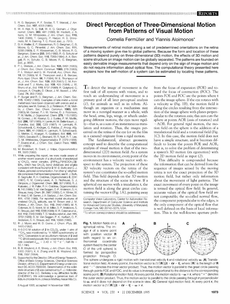
Fig. 1. Motion fields on a A A B 4 c spherical retina. The im- age r of a scene po~nt with position vector R (with regard to an or- thonormal coordinate system fixed to the center 0 of the unit sphere) is formed by perspective wroiection throuah 0. , , - The sphere undergoes a rigid motion with translational velocity t and rotational velocity a. (A) Transa- tional motion field. At every point r, the motion vector is (1/1 ~ / ) [ ( t . r)r - t], where / R I is the length of R and " . " denotes the inner vector product. Thus, the motion vector is parallel to the great circle passing through points FOE and FOC, and its value is inversely proporiiona to the distance to the corresponding scene point. (B) Rotational motion field. At every pont r, the motion vector is a X r, where " X " denotes the outer vector product. Thus, the moton vector is parallel to the circle passlng through r perpendcuar to a, and it does not depend on the scene in view, (C) General rigid motion field. At every point r, the motion vector IS (I// Rl)[(t . r)r - t] - o x r.
SCIENCE VOL. 270 2 2 DECEMBER 1995 1973
lem. In many cases, it is possible to obtain additional flow information for areas (patch- es) in the image. Thus, the input that any system can use for further motion processing is some partial optical flow information. Our analysis is based on a minimum amount of knowledge about image motion, namely the sign of the projection of optical flow along directions where it can be robustly comput- ed. These measurements along a set of ap- propriately chosen orientations possess a rich global structure; they give rise to simple pat- terns in the image surface, and the location and form of these patterns encode the 3D motion parameters independently of the depth of the scene in view. The selected orientations are defined below.
Two classes of orientations are defined with regard to an axis. Consider an axis s passing through the center of a spherical eye and cutting the sphere at points N and
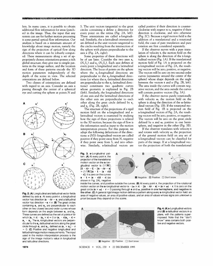
Fig. 2. (A) Longitudinal and latitudinal vector fields defined by axis s. At every point r, a longitudinal vector has direction (s . r)r - s, and a latitudinal vector has direction -s x r. (B) The great circles containing s, and s2 are perpendicular to each other on two closed second-order curves whose form depends on the angle between s, and s,. These curves are defined as the set of points r for which (s, x r) - (s, x r) = 0 or (s, . r)(s, . r) = s, . s,. The s,-longitudinal vectors are perpen- dicular to the s2-latitudinal vectors along the great circle through s, and s,, defined as (s, x s,) r = 0. (C) Positive and negative longitudinal and latitudinal image motion measurements. The input used in the motion interpretation process is the sign of the image motion's value in longitudinal and latitudinal directions.
S. The unit 'vectors tangential to the great circles containing s define a direction for every point on the retina (Fig. 2A, left). These orientations are called s-longitudi- nal. Similarlv. the s-latitudinal orientations , . are defined as the unit vectors tangential to the circles resulting from the intersection of the sphere with planes perpendicular to the axis s (Fig. 2A, right).
Some properties of these directions will be of use later. Consider the two axes sl (NISI) and s, (N,S,). Each axis defines at every point a longitudinal and a latitudinal direction. The locus of points on the sphere where the sl-longitudinal directions are perpendicular to the s,-longitudinal direc- tions (or where the s,-latitudinal directions are perpendicular to the s2-latitudinal direc- tions) constitutes two auadratic curves whose geometry is explained in Fig. 2B (left). Similarly, the longitudinal directions of one axis and the latitudinal directions of the other axis are perpendicular to each other along the great circle defined by sl and s, (Fig. 2B, right).
The structure of the projections of a rigid motion field on the s-longitudinal and s- latitudinal vectors is examined bv studvine , - how the sign of these projections is related to the 3D motion, because the sien of flow is - the information used as input to the motion interpretation process. For this purpose, we adopt the following definitions of the direc- tions: s (NS)-longitudinal vectors are called positive if they point away from N, negative if they point away from S, and zero other- wise. Similarly, s-latitudinal vectors are
called positive if their direction is counter- clockwise with respect to s, negative if their direction is clockwise, and zero otherwise (Fig. 2C). Because a rigid motion field is the addition of a translational and a rotational field, the cases of pure translation and pure rotation are first considered separately.
If the observer moves with a pure trans- lation of velocity t, the motion field on the sphere is along the direction of the t-longi- tudinal vectors (Fig. 1A). If the translational motion field of Fig. 1A is projected on the s-longitudinal vectors of Fig. 2A, the result- ing vectors will be zero, positive, or negative. The vectors will be zero on two second-order curves (symmetric around the center of the sphere) whose shape depends on the angle between the vectors t and s (Fig. 2B, left). The area inside the curves will contain nee- - ative vectors, and the area outside the curves will contain positive vectors (Fig. 3A).
If the observer moves purely rotationally with velocity w, the motion field on the sphere is along the direction of the w-latitu- dinal vectors (Fig. 1B). If the rotational mo- tion field of Fig. 1B is projected on the s-longitudinal vectors of Fig. 2A, the result- ing vectors will be zero, positive, or negative. The vectors will be zero on the great circle defined by s and w, positive in one hemi- sphere, and negative in the other (Fig. 3B).
If the observer translates with velocity t and rotates with velocitv w. the ~roiection , , . , of the general motion field on any set of s-longitudinal vectors can be classified for - parts of the image. If at a longitudinal vec- tor the projection of both the translational
Fig. 3. s-Longitudinal pat- A B c a,
tern. (A) At every point r, the projection of the translational motlon vector on the s-Ion- gitudlnal vector IS (l/IRI) [(t - r)r - t] . [(s . r)r - s] 5-' , ,' - /.' -. '\
= ( l / I ~ l ) [ s t -(s - r)(t \U , /', , . - r)]. It IS zero on the curves / \' .- , -1 1--',
s . t = (S . r)(t . r) (as Negative Positive Don't know shown in Fig. 2A), negative inside the curves, and positive outside the curves. (B) At every point r, the projection of the rotational motion vector on the s-longitudinal vector is -(w x r) [(s - r)r - s] = (s x w) . r. It is zero on the great circle (s x w) r = 0 passing through s and w, positive in one hemisphere, and negative in the other. (C) A general rigid image motion defines a pattern along every s-longitudinal vector field: an area of negative values, an area of positive values, and an area of values whose signs are unknown a priori because they depend on the scene.
A B Fig. 4. (A) s-Longitudinal vectors and (B) s-latltudlnal vectors In a plane, wlth the patterns super- Imposed. Note that the "don't know" area conta~ns both PSI- tlve and negatlve vectors.
' I
Negative Positive Don't know
SCIENCE VOL. 270 22 DECEMBER 1995
and rotational vectors is positive, then the projection of the image motion (the sum of the translational and rotational vectors) will also be positive. Similarly, if the pro- iections of both the translational and rota- tional vectors on a longitudinal vector at a point are negative, the projection of the motion vector at this point will also be negative. In other words, if the values along an s-longitudinal field (Fig. 3, A and B) are added, whenever positive and positive come together, the result will be positive, and whenever negative and negative come to- gether, the result will be negative. Howev- er, whenever positive and negative come together, the result can be either positive or negative. In such a case, the sign of the projection of the rigid motion vector de- pends on the value of the translational and rotational vector components, and thus on the length of the vectors t and o and the depth of the scene. [Actually, this "don't know" area also contains information re- garding 3D motion and structure (3).]
The distribution of the sign of image motion along the s-longitudinal set of di- rections thus defines a pattern on the sphere. A pattern like that shown in Fig. 3C is obtained for a general rigid motion field that arises from a translation t and a rota- tion o on an s-longitudinal set of direc- tions. This Dattern consists of an area of strictly positive values, an area of strictly negative values, and an area (covering half of the sphere) in which the values are either positive or negative depending on the vec- tors t and o and the d e ~ t h of the scene. The pattern is characterized by one great circle containing o and s and by two qua- dratic curves containing the points FOE, FOC, N, and S. For every pattern, half of the sphere carries valuable information (positive or negative) and the other half does not: however. the locations of these areas are different' for different patterns.
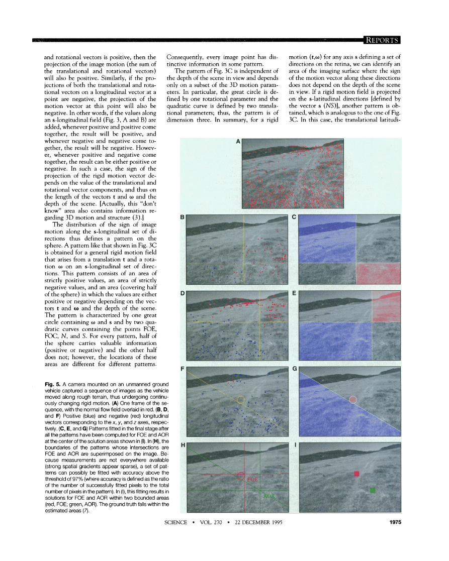
Fig. 5. A camera mounted on an unmanned ground vehicle captured a sequence of images as the vehicle moved along rough terrain, thus undergoing continu- ously changing rigid motion. (A) One frame of the se- quence, with the normal flow field overlaid in red. (6, D, and F) Positive (blue) and negative (red) longitudinal vectors corresponding to the x, y, and z axes, respec- tively. (C, E, and G) Patterns fitted in the final stage after all the pattems have been computed for FOE and AOR
Consequently, every image point has dis- tinctive information in some pattern.
The pattem of Fig. 3C is independent of the depth of the scene in view and depends only on a subset of the 3D motion param- eters. In particular, the great circle is de- fined by one rotational parameter and the quadratic curve is defined by two transla- tional parameters; thus, the pattern is of dimension three. In summary, for a rigid
motion (t,o) for any axis s defining a set of directions on the retina, we can identify an area of the imaging surface where the sign of the motion vector along these directions does not depend on the depth of the scene in view. If a rigid motion field is projected on the s-latitudinal directions [defined by the vector s (NS)], another pattern is ob- tained, which is analogous to the one of Fig. 3C. In this case, the translational latitudi-
at the center of the solution areas shown in (I). In (H), the boundaries of the pattems whose intersections are " FOE and AOR are superimposed on the image. Be- cause measurements are not everywhere available (strong spatial gradients appear sparse), a set of pat- terns can possibly be fmed with accuracy above the threshold of 97% (where accuracy is defined as the ratio of the number of successfully fmed pixels to the total number of pixels in the pattem). In (I), this fming results in solutions for FOE and AOR within two bounded areas (red, FOE; green, AOR). The ground truth falls within the estimated areas (7).
SCIENCE VOL. 270 22 DECEMBER 1995 1975
nal flow is separated into positive and neg- ative by a great circle, and the rotational flow is separated into positive and negative by two closed quadratic curves (as in Fig. 2B) passing from the points AOR, -AOR, N , and S.
The geometric analysis described above allows us to formulate the problem of ego- motion estimation as a pattern recognition problem. Assume that the system has the capability of estimating the sign of the ret- inal motion along a set of directions defined by various s-longitudinal or s-latitudinal fields. If the system can locate the patterns in each longitudinal and latitudinal vector u
field, then it has effectively recognized the directions t and w 14). The intersections of the quadratic curves of the patterns in Fig. 3 C orovide the noints FOE and FOC, and the 'intersection; of the great circles of the patterns in Fig. 3C provide the points AOR and -AOR. Each single pattern provides only constraints on the locations of FOE and AOR, but a collection of patterns con- strains these locations to small areas or even to single points. The amount of information available for pattern fitting depends on the computational power of the system, and this information in turn influences the accuracy of the localization of FOE and AOR 15). If the system is able to derive optical'flow, then it is able to estimate the sign of the projection of the flow along any direction, and thus for every pattern at every point where information is available. If, however, the system is less powerful and can only compute the motion in one direction (nor- mal flow) or the sign of the motion in a few directions, then the solution proceeds ex- actly as before. The difference is that for each longitudinal or latitudinal set of direc- tions, information (positive, negative, or zero) is not available at every point of the sphere, and consequently the uncertainty may be larger and FOE and AOR may be obtained only within bounds.
After the directions of t and w are esti- mated from the sign of the flow along vari- ous directions, the length of w (that is, the exact rotation) can easily be estimated from the values of flow measurements (6). Also, after deriving 3D motion from the informa- tion supplied by the patterns, the system can estimate optical flow to derive the 3D scene structure and to estimate FOE and AOR more accurately. Usually, in a working sys- tem, information from other senses is used in addition. This information mav come from inertial sensors, such as gyros and acceler- ometers in robotic svstems or vestibular mechanisms in biological systems.
For the case of a planar retina, the s- longitudinal vectors become perpendicular to conic sections defined bv the intersection of the image plane with a family of cones of axis s (Fig. 4A). Analogously, the s-latitu-
dinal vectors become perpendicular to straight lines passing through the intersec- tion so of axis s with the image plane (Fig. 4B). The ereat circle and the second-order - curve that characterize the patterns of posi- tive and negative vectors become a straight line and a conic section, respectively.
A Dart of the theor!] described here has been ikplemented and'tested on a number of calibrated indoor image sequences, with excellent results (6). The solutions for FOE and AOR were always bounded areas that contained the ground truth (7) and were not larger than 2' of the visual field. Figure 5 shows an outdoor image sequence exper- iment with an unmanned ground vehicle. In this exoeriment, the onlv innut was the , sign of th' normal flow at image points with strong spatial gradients.
The pattern-matching approach to ego- motion estimation does not directly relate to traditional computational studies of the per- ception of 3D motion. With a few excep- tions (a), such studies addressed the problem in two steps. In the first step, the optical flow was estimated as an a~oroximation to the
. A
motion field; in the second step, the 3D motion was estimated through a local de- composition of the optical flow field (9-1 2). In the scheme described here, the retinal motion information used is equivalent to the sign of the optical flow along some direction. In other words, for a vector v on the image, the information needed is whether the image motion along the line defined by the vector v has the sign of v or -v. This is a robust
property of the optical flow, and, as demonstrated here, it is sufficient for the task of egomotion perception when used with the introduced global constraints. It has been argued (1 3) that qualitative estimates of optical flow are often sufficient for many tasks; for instance, the task of detecting a potential crash (14) may not even require a precise measurement of the normal cotnpo- nent of the flow. As suggested in (IS), "it is sufficient that the itnaee motion estimate be qualitatively consistent with the perspective 2D projection of the 'true' 3D velocity field. Even estimates that don't correspond to im- age velocity, like the ones derived by Reichardt's correlation model or equivalent energy ~nodels (16), may be acceptable for several visual tasks if the estimates are con- sistent over the visual field" (pp. 131-132). The pattern-based approach to the problem of egomotion estimation demonstrates the feasibility of such ideas about qualitative vi- sual motion analysis. The ideas described here ma\] relate to neuroscience exneriments In which primates were found to have cells that respond to patterns of visual motion (17), and psychologists may find a link be- tween the patterns described here and the transformational invariants in Gibson's the- ory (18) of direct perception.
REFERENCES AND NOTES
1. Y. Aloimonos and A. Rosenfeld, Science 253, 11 81 (1991); Y. Alomonos and D. Shulman, Integration of Visual Modules: An Extension of the Marr Paradigm (Academc Press, Boston, 1993).
2. Computer vslon researchers usually refer to egomo- tion estimation as the problem of recovering FOE and the exact rotation. However, the sign of the flow flelds used here allows for the computation of the rotation only up to a constant multipl~cat~on factor: that is, only AOR can be derived.
3. C. Fermuller and Y. Aloimonos, Tech. Rep. CAR-TR- 732 (Center for Automation Research, Unversity of Malyland, College Park, 1994).
4. The partcular structure of the postive and negative vectors In the "don't know" area (19) makes it pos- sible to localize the patterns vely efficiently by searching only a small part of the Image and using standard computational techniques.
5. The accuracy of the localization of FOE and AOR also depends on the structure of the scene in view. In an analysis of the relatlon between 3D rigid motion and complete directonai moton fields (201, it was found that theoretically there is almost always enough in- formation in the direction of motlon fields to recover 3D motlon uniquely. Ambguity can occur only for surfaces In view that Ile In a particular area bounded by surfaces of a second and thrd order.
6. C. Fermullerand Y. Aloimonos, lnt. J. Comput. Vision 15, 7 (1 995); ibid. 11, 165 (1 993); C. Fermuller, In Special Issue on Qualltatlve Vlsion, Y. Alo~monos, Ed., ibid. 14, 147 (1 995).
7. The ground truth was derived from inertla1 sensor data and from a photogrammetric numerical soluton (9, 11) that used manual correspondences of Image features.
8, J. Alolmonos and C. M. Brown, in Proc. Workshop on Computer Vision: Representation and Control (IEEE Computer Socety, Annapolis, MD, 1984), pp. 72-77; B. K. P. Horn and E. J. Weldon, in Proc. International Conference on Computer Vision (IEEE Computer Society. London, 1987), pp. 2-1 1
9. H. C. Longuet-Higgns, Nature 293, 133 (1981). 10. - a n d K. Prazdny, Proc. R. Soc. London Ser. B
208, 385 (1984); J. J. Koenderink, Vision Res. 26, 161 (1 986).
11. R. Y. Tsa andT. S. Huang, IEEE Trans. Pattern Anal. Machine lntell. 6, 13 (1 984); 0. Faugeras and S. Maybank, lnt. J. Comput. Vision 4, 225 (1 990).
12. S. Ullman, The Interpretation of Visual Motion (MIT Press, Cambrdge, MA, 1979).
13. A. Verrl and T. Pogg~o, IEEE Trans. Pattern Anal. Machine lntell. 11 , 490 (1 989).
14. R. C. Nelson and J. Y. Alo~monos, ibid 11, 1102 (1 989).
15. N Ancona and T Poggo, in Special lssue on Qual- itatlve Vlson, Y. Aloimonos, Ed., lnt. J. Comput. Vi- sion 14, 131 (1 995)
16. W. Relchardt, In Principles of Sensory Communica- tion, W. A. Rosenbllth, Ed. (Wlley, New York, 1961), pp. 303-31 7: J. Comp. Physiol. 161, 533 (1 987); T. Poggio and W. Relchardt, Kybernetik 13, 223 (1 973); J. P. H, van Santen and G. Sperling. J. Opt Soc Am. A 1, 451 (1 984).
17. C. J, Durn and R. H. Wurtz, J. Neurophysiol. 65, 1329 (1 991); K. Tanalta and H. A. Saito, ibid 62,626 (1 989).
18. J. Gbson, The Ecological Approach to Visual Per- ception (Houghton Mifflln. Boston. 1979)
19. C. Fermuller, in Active Perception, Y. Alomonos, Ed. (Erlbaum, Hillsdale, NJ, 1993), pp. 103-150: - and Y. Aloimonos, In VisDal Navigation: From Biolog- ical Systems to Unmanned Ground Vehicles, Y. Alo- imonos, Ed, (Erlbaum, Hillsdale, NJ, In press).
20. T. Brodsky, C. Fermuller, Y. Alomonos, Tech. Rep CAR-TR-780 (Center for Automation Research, Uni- versity of Malyland, 1995).
21. Supported by Advanced Research Projects Agency grant DAA H04-93-G-0419, Offlce of Naval Re- search grant N00014-93-1-0257, and NSF grant IRI-9057934 (under a President~al Young lnvestiga- tor Award)
24 May 1995, accepted 26 October 1995
1976 SCIENCE VOL. 270 22 DECEMBER 1995