Embed Size (px)
Citation preview
UNIVERSITY OF LJUBLJANA
FACULTY OF ELECTRICAL ENGINEERING
DIRECTIONAL PROTECTION
Seminar work in the course Distribution and industrial networks
Mentor: Author:
Prof. Grega Bizjak Amar Zejnilović
Ljubljana, May, 2018.
DIRECTIONAL PROTECTION
2
Abstract
Power system protection is extremely important in order to achieve satisfactory level of
reliability and security of the distribution system. One of the most used protection that is used
in distribution networks is overcurrent protection. In traditional, radial, distribution networks
this overcurrent protection was enough. But in modern networks with more than one power
source, or in networks that have multiple lines for conveying electrical power the directional
protection is essential in order to achieve selectivity. Directional overcurrent relaying refers
to relaying that can use the phase relationship of voltage and current to determine direction of
a fault. Generally, there are three types of directional protection: phase directional protection,
earth fault directional protection and active and reactive directional power protection and all
three groups will be explained in this seminar paper.
DIRECTIONAL PROTECTION
3
Contents 1. Introduction .................................................................................................................................... 5
2. Distribution network with 2 or more power sources ..................................................................... 5
2.1 Principle of operation ............................................................................................................. 7
2.2. Characteristic angle .................................................................................................................... 11
2.3 Directional relay construction ............................................................................................... 14
3 Protection of parallel distribution lines ........................................................................................ 16
4 Protection of closed loop .............................................................................................................. 19
5 Earth fault directional protection ................................................................................................. 20
6 Power relays .................................................................................................................................. 22
7 Conclusion ..................................................................................................................................... 23
References: ........................................................................................................................................... 24
QUESTIONS ........................................................................................................................................... 24
EXAMPLE: .............................................................................................................................................. 25
DIRECTIONAL PROTECTION
4
Figure 1: A radial distribution system with 2 power sources ................................................................. 6
Figure 2: short circuit protection on a network with a two sources ...................................................... 6
Figure 3. (b): current flows in forward direction .................................................................................... 7
Figure 4. (a): circuit diagram ................................................................................................................... 8
Figure 5: Selecting a characteristic angle to properly align the forward and reverse direction zones of
the directional overcurrent relay ............................................................................................................ 9
Figure 6: polarizing voltage of (a) phase "A “and (b) phase "C" for a current in phase "A" and phase
"C" respectively [5] ............................................................................................................................... 10
Figure 7: Directional protection tripping zones on (a) phase "A" and (b) phase "C" for a θ=45°[5] .... 10
Figure 8: Range of phase angle values of current IA expected for a phase-to-ground fault on phase A
.............................................................................................................................................................. 11
Figure 9: Ranges of phase angle values of current IA expected for phase-to-phase faluts between
phases A and B and between phases A and C ...................................................................................... 12
Figure 10: Range of phase angle values of current Ia expected for faults on phase A ......................... 12
Figure 11: setting the characteristic angle to 45° properly aligns the forward and reverse direction of
the directional overcurrent relay with the range of phase angle values expected for the fault currents
.............................................................................................................................................................. 13
Figure 12: setting the characteristic angle to 30° and 60° properly aligns the forward and reverse
direction of the directional overcurrent relay with the range of phase angle values expected for the
fault currents: ....................................................................................................................................... 13
Figure 13: Two lines in parallel to convey power to a substation ........................................................ 16
Figure 14: protection of two parallel line using just overcurrent relays [4] ......................................... 17
Figure 15: Directional overcurrent protection of two power lines connected in parallel .................... 18
Figure 16: protection of a closed loop using directional relays and time-based selectivity ................. 19
Figure 17: measuring the residual current using 3 CT’s (figure above), and using a ring (figure below)
.............................................................................................................................................................. 20
Figure 18: measuring the residual voltage using 3 VT with two secodary windings (a), and using
auxiliary VT’s (b) .................................................................................................................................... 21
Figure 19: Layout diagram for measuring power [1] ............................................................................ 22
DIRECTIONAL PROTECTION
5
1. Introduction
Protection equipment has the basic role of detecting an electrical fault and disconnecting
that part of the network in which the fault occurs limiting the size of the disconnected section
as far as possible. In modern medium-voltage (MV) distribution lines and in almost all high
voltage transmission lines, a fault can be in two different directions from a relay and it is
highly desirable for a relay to respond differently for faults in the forward or reverse
direction. In fact, in almost all situations the relay should respond only when the fault is on
one side, while for failures on the other side it remains inactive. And because of this, the
usage of directional protection is important in order to avoid disconnection of unnecessary
circuits. As normal overcurrent relays cannot provide this function, a directional unit is added
to activate the relay when the fault current flow is in a predetermined direction.
Directional protection enables better discrimination of the faulty part of the network than
with overcurrent protection. It is necessary to use it in the following conditions: [1]
in a system with several sources
in closed loop or parallel-cables systems
in isolated neutral systems for the feedback of capacitive current
and to detect an abnormal direction of flow of active or reactive power
(generators)
Directional protection is used for all network components in which the direction of flow
of power could change, for example for the short circuit between phases or for an earthing
fault (single phase fault): [1]:
phase directional protection is installed to protect two connections operated in
parallel, a loop or a network component connected to two power sources
earth fault directional protection is sensitive to the direction of flow of the
current to earth. It is necessary to install this type of protection equipment
whenever the phase to earth fault current is divided between several earthing
systems.
active and reactive directional power protection equipment is used to detect
abnormal power flow other than the one due to a short circuit; e.g.: in the
event of the failure of the prime mover, a generator will continue to run as a
synchronous motor, drawing power form the system.
The IEEE device number used to signify a directional element is 67-directional
overcurrent, generally based on the phase relationship of V (voltage) and I (current), with no
distance to fault capability. [2]
In the following pages of this seminar paper, all above mentioned usages of directional
protection will be describe in more details and while describing the usages, the operating
principle of relay will be explained as well.
2. Distribution network with 2 or more power sources
In this chapter, the usage of directional protection will be described on a network with 2
power sources. The problem, as well as the solution, will be described using the figure 1
which describes already mentioned distribution network:
DIRECTIONAL PROTECTION
6
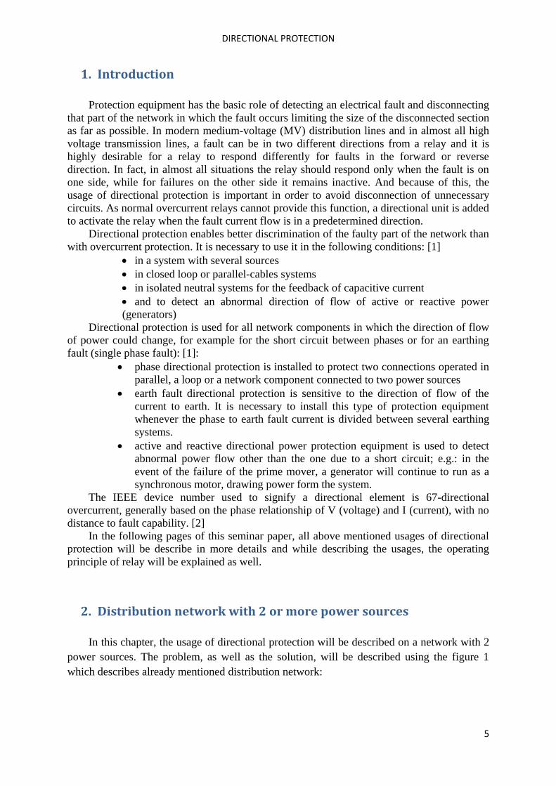
Figure 1: A radial distribution system with 2 power sources
Figure 1 shows the system which is radial but it has two sources connected to it. A and B
are power sources, C,D and E are busbars, F1 and F2 are places where short circuit happens
and the green and red squares are overcurrent relays. The circled relays are also directional
overcurrent relays, but for better explanation of the directional relays, it will be assumed that
are these regular overcurrent relays. With this assumption, the fault F1 will be analysed.
When short circuit F1 happens, both power sources supply this fault with current. It is
obvious that red relays should open and on that way separate part of the network where is
short current from the rest of the network. But without directional relays, it is a high
probability that one of the green relays would open before circled red relay and on that way
selectivity is not fulfilled because the distribution line between busbars C and D is out of
function although the fault isn’t on that distribution line. To overcome this problem, the relay
element has to be provided with additional discrimination feature to distinguish between
faults that it should respond to, and others that it shouldn’t. So, instead of regular overcurrent
relays, the circled relays on the figure 1 should be directional relays and on that way green
circled relay would never open when the fault is F1, as well as the red circled relay would
never open when the fault is F2. There is still one problem in this network that should be
solved, and that is: how to avoid the unnecessary operation of the green relay that is not
circled when the fault is F1? The reason why it’s not possible to use directional relays here is
that if this relay is directional relay it would never open, even when it should react, for
example when the fault is F2. The answer on previous questions could be seen on a figure 2:
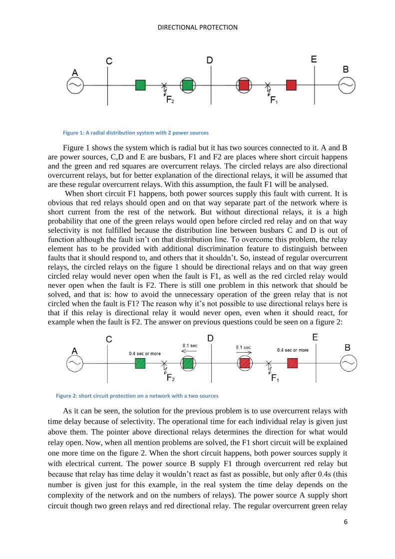
Figure 2: short circuit protection on a network with a two sources
As it can be seen, the solution for the previous problem is to use overcurrent relays with
time delay because of selectivity. The operational time for each individual relay is given just
above them. The pointer above directional relays determines the direction for what would
relay open. Now, when all mention problems are solved, the F1 short circuit will be explained
one more time on the figure 2. When the short circuit happens, both power sources supply it
with electrical current. The power source B supply F1 through overcurrent red relay but
because that relay has time delay it wouldn’t react as fast as possible, but only after 0.4s (this
number is given just for this example, in the real system the time delay depends on the
complexity of the network and on the numbers of relays). The power source A supply short
circuit though two green relays and red directional relay. The regular overcurrent green relay
DIRECTIONAL PROTECTION
7
wouldn’t open as fastest as it could because of the time delay, the directional green relay
wouldn’t react at all because the direction of current is in the opposite of the direction of
reaction of this relay, and on the end, directional red relay would react because the direction
of the current is the same as the direction in which relay operate. With the reaction of this
relay, power source A stops supplying short current with the electricity, but power source B
still remains because regular red relay has time delay. But after 0.4sec after the fault happen
this relay would also react and the power sources wouldn’t supply short circuit anymore,
distribution line DE would be out of use, but line CD would continue with its normal
operation, which would not be possible without directional relays.
2.1 Principle of operation
After explaining one of the usages, the following question could be asked: how does
direction relay works? How does it recognize the direction of current flow, keeping in mind
that distribution network is network with AC and the direction of current is changing
constantly?
The solution for this is that in AC power networks, the direction of current flow is
determined from the phase shift between the voltage E and the current I at any given point of
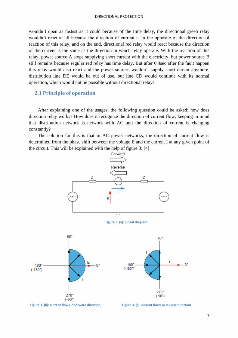
the circuit. This will be explained with the help of figure 3: [4]
Figure 3. (a): circuit diagram
Figure 3. (b): current flows in forward direction Figure 3. (c): current flows in reverse direction
DIRECTIONAL PROTECTION
8
When the current flows from left to right in the circuit, the absolute value of the phase
shift between the voltage and current is 90° or less (Figure 3b), the exact value of the phase
shift being dependent on the value of the circuit impedance Z. This direction is generally
considered as the forward direction. On the other hand, when the current flows from right to
left in the circuit, the absolute value of the phase shift between the voltage and current is 90°
or more (Figure 3c), the exact value of the phase shift being dependent on the value of the
circuit impedance Z. This direction is generally considered as the reverse direction.
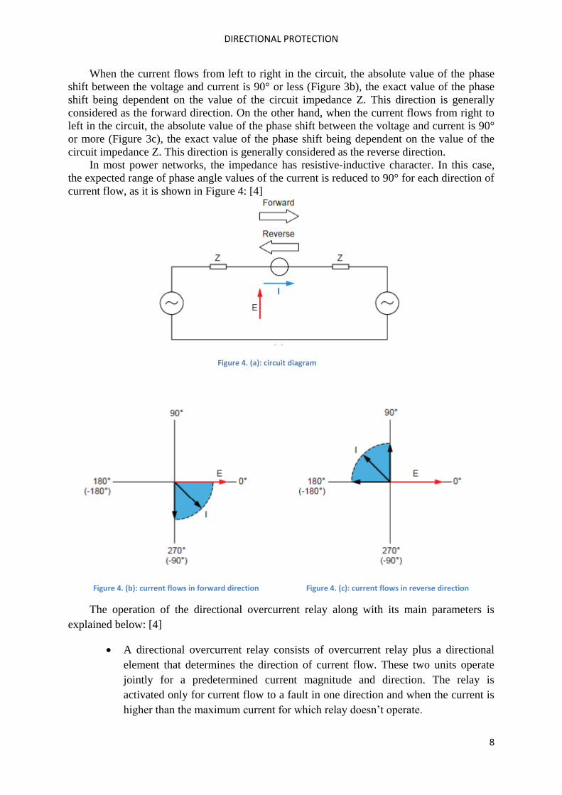
In most power networks, the impedance has resistive-inductive character. In this case,
the expected range of phase angle values of the current is reduced to 90° for each direction of
current flow, as it is shown in Figure 4: [4]
Figure 4. (a): circuit diagram
Figure 4. (b): current flows in forward direction Figure 4. (c): current flows in reverse direction
The operation of the directional overcurrent relay along with its main parameters is
explained below: [4]
A directional overcurrent relay consists of overcurrent relay plus a directional
element that determines the direction of current flow. These two units operate
jointly for a predetermined current magnitude and direction. The relay is
activated only for current flow to a fault in one direction and when the current is
higher than the maximum current for which relay doesn’t operate.
DIRECTIONAL PROTECTION
9
A directional overcurrent relay can monitor line current on two phases, on that
way measuring two currents and two voltages. With this kind of operation, any
phase-to-phase fault can be detected. In the case of monitoring line current on all
three phases, the relay measures three currents and three voltages. This allows
detection of any phase-to-phase fault as well as any phase-to-ground fault.
In electromechanical and static directional overcurrent relays, the reference
voltage for phase A is generally voltage EBC (VBC), and not phase voltage EA
(VA) as it could be expected. This is because voltage EBC isn’t affected when a
ground fault occurs on phase A, thereby providing a more stable reference
voltage. It is analogous for the phases B and C. This will be explained in more
details further in the paper. This logic could not be used for modern directional
overcurrent relays (digital and numerical units) because these relays generally
use phase voltage EA as the reference voltage for phase A and other techniques to
obtain a reference voltage that is even more stable (these techniques are beyond
the scope of this seminar paper, and because of that modern relays won’t be
further explained). However, there is still a reason to study electromechanical
and static directional relays because some of their principles and settings are used
in modern directional overcurrent relays even if a phase-to-phase voltage is used
as the reference voltage instead of a phase voltage.
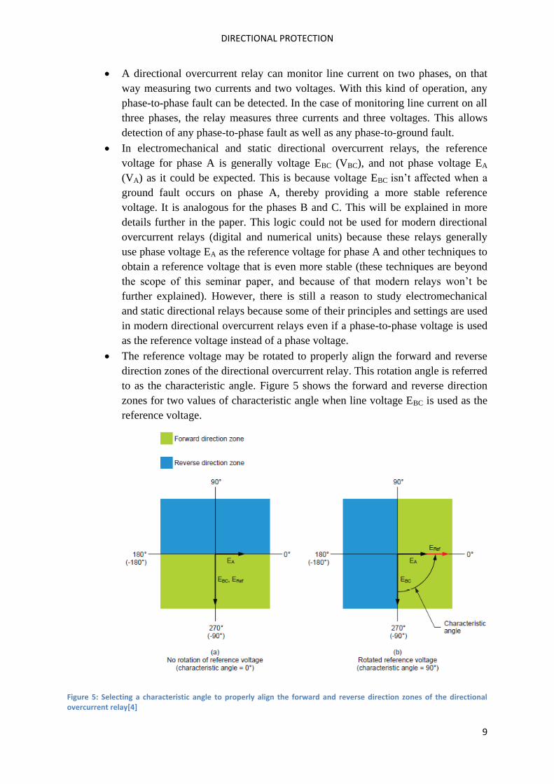
The reference voltage may be rotated to properly align the forward and reverse
direction zones of the directional overcurrent relay. This rotation angle is referred
to as the characteristic angle. Figure 5 shows the forward and reverse direction
zones for two values of characteristic angle when line voltage EBC is used as the
reference voltage.
Figure 5: Selecting a characteristic angle to properly align the forward and reverse direction zones of the directional overcurrent relay[4]
DIRECTIONAL PROTECTION
10
As it is already mentioned, in order to detect the current direction, the phase
displacement between voltage and short circuit current must be determined. When is
cos(φ)≥0 (-
) then the active power seen by the directional relay is positive. The
active power seen by the directional relay is negative in the situation when is cos(φ)≤0
(
) .
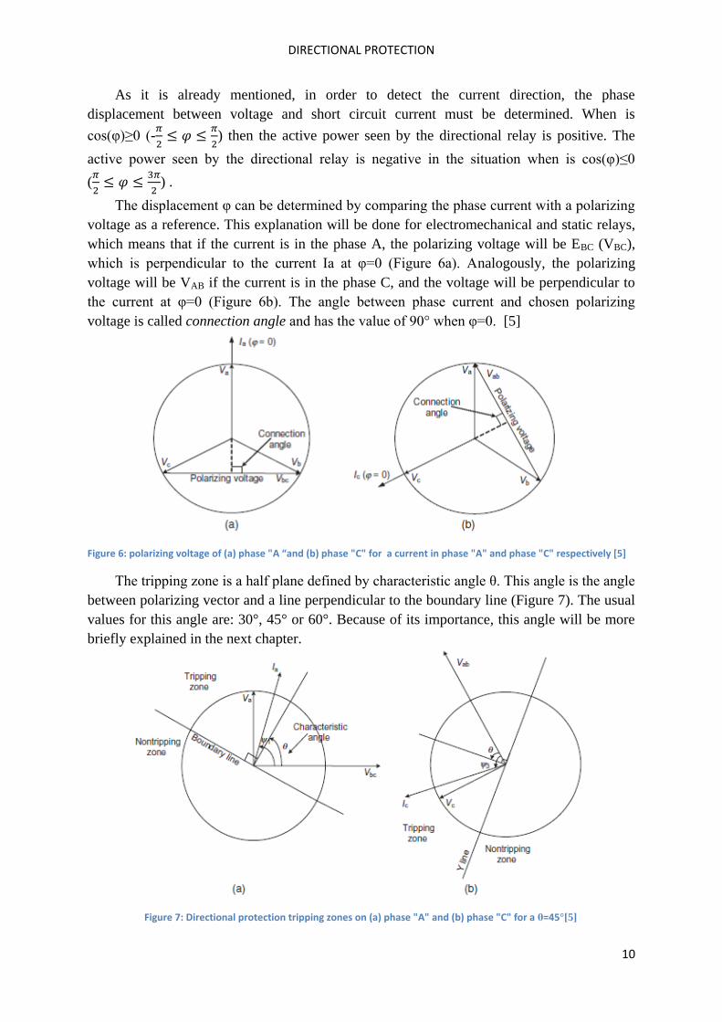
The displacement φ can be determined by comparing the phase current with a polarizing
voltage as a reference. This explanation will be done for electromechanical and static relays,
which means that if the current is in the phase A, the polarizing voltage will be EBC (VBC),
which is perpendicular to the current Ia at φ=0 (Figure 6a). Analogously, the polarizing
voltage will be VAB if the current is in the phase C, and the voltage will be perpendicular to
the current at φ=0 (Figure 6b). The angle between phase current and chosen polarizing
voltage is called connection angle and has the value of 90° when φ=0. [5]
Figure 6: polarizing voltage of (a) phase "A “and (b) phase "C" for a current in phase "A" and phase "C" respectively [5]
The tripping zone is a half plane defined by characteristic angle θ. This angle is the angle
between polarizing vector and a line perpendicular to the boundary line (Figure 7). The usual
values for this angle are: 30°, 45° or 60°. Because of its importance, this angle will be more
briefly explained in the next chapter.
Figure 7: Directional protection tripping zones on (a) phase "A" and (b) phase "C" for a θ=45°[5]
DIRECTIONAL PROTECTION
11
It can be seen that phase current Ia is in the tripping zone when θ-π/2<ψ1<θ+π/2 and for
the other half plane is in the nontripping zone. The similar conclusion could be made for
current Ic. This current is in the tripping zone when θ-π/2<ψ3<θ+π/2 and is in the nontripping
zone for all other angles. Angles ψ1 and ψ3 correspond to φ1 and φ2, respectively (φi= ψi+90°)
2.2. Characteristic angle
To determine the direction of the fault, the protection equipment measures the phase
displacement between the current and the polarisation variable. If the polarisation variable is
not in the axis of symmetry of the wished relay’s action, it’s necessary to re-phase it by
adjusting the characteristic angle. This angle must be determined in the process of designing
the protection coordination so any fault in the chosen direction causes a current that falls in
the tripping zone and that any current in the other direction causes a current falling outside of
this zone. The analyses will be done for typical values of characteristic angle θ=30°,θ=45°
and θ=60° and for three faults: phase-to-ground fault, a phase-to-phase fault between phases
A and B, and a phase-to-phase fault between phases A and C. These three faults will be
analyses separately. Also, the resistive-inductive character of the impedance will be assumed
(This assumption is almost always true).
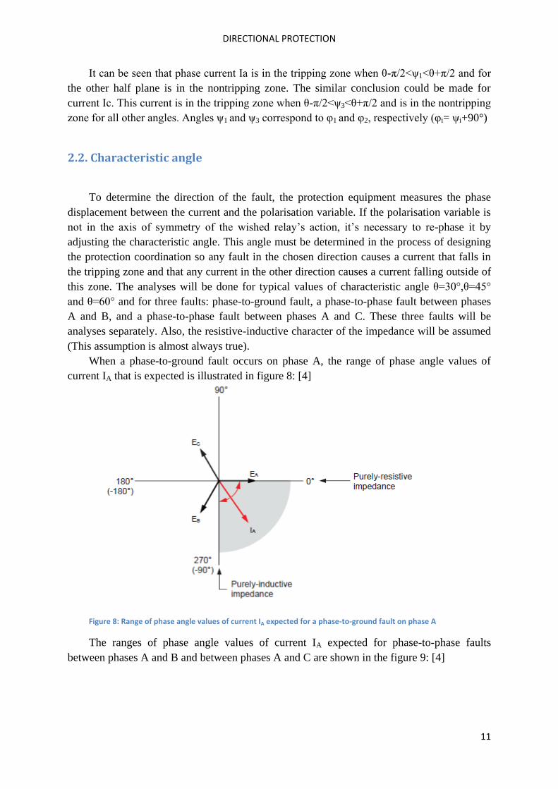
When a phase-to-ground fault occurs on phase A, the range of phase angle values of
current IA that is expected is illustrated in figure 8: [4]
Figure 8: Range of phase angle values of current IA expected for a phase-to-ground fault on phase A
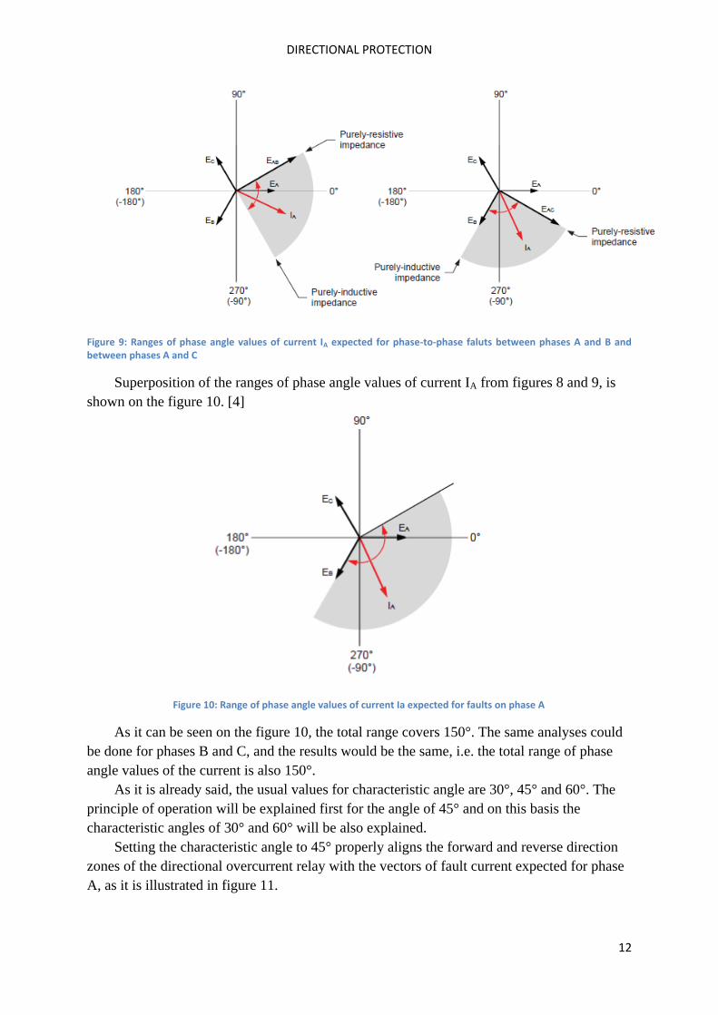
The ranges of phase angle values of current IA expected for phase-to-phase faults
between phases A and B and between phases A and C are shown in the figure 9: [4]
DIRECTIONAL PROTECTION
12
Figure 9: Ranges of phase angle values of current IA expected for phase-to-phase faluts between phases A and B and between phases A and C
Superposition of the ranges of phase angle values of current IA from figures 8 and 9, is
shown on the figure 10. [4]
Figure 10: Range of phase angle values of current Ia expected for faults on phase A
As it can be seen on the figure 10, the total range covers 150°. The same analyses could
be done for phases B and C, and the results would be the same, i.e. the total range of phase
angle values of the current is also 150°.
As it is already said, the usual values for characteristic angle are 30°, 45° and 60°. The
principle of operation will be explained first for the angle of 45° and on this basis the
characteristic angles of 30° and 60° will be also explained.
Setting the characteristic angle to 45° properly aligns the forward and reverse direction
zones of the directional overcurrent relay with the vectors of fault current expected for phase
A, as it is illustrated in figure 11.
DIRECTIONAL PROTECTION
13
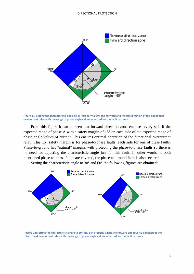
Figure 11: setting the characteristic angle to 45° properly aligns the forward and reverse direction of the directional overcurrent relay with the range of phase angle values expected for the fault currents
From this figure it can be seen that forward direction zone encloses every side if the
expected range of phase A with a safety margin of 15° on each side of the expected range of
phase angle values of current. This ensures optimal operation of the directional overcurrent
relay. This 15° safety margin is for phase-to-phase faults, each side for one of these faults.
Phase-to-ground has “natural” margins with protecting the phase-to-phase faults so there is
no need for adjusting the characteristic angle just for this fault. In other words, if both
mentioned phase-to-phase faults are covered, the phase-to-ground fault is also secured.
Setting the characteristic angle to 30° and 60° the following figures are obtained:
Figure 12: setting the characteristic angle to 30° and 60° properly aligns the forward and reverse direction of the directional overcurrent relay with the range of phase angle values expected for the fault currents:
DIRECTIONAL PROTECTION
14
As it can be seen from previous figure, all three faults are covered when the
characteristic angles is 30° or 60°. The only difference is in the margins; on what side are
they and what their value is. In these two cases, a safety margin is 30° but just on one side.
All the figures are done with the help of Autocad.
After explaining the operation of the directional overcurrent relays, the other usages of
this protection will be shown in the rest of this seminar paper.
2.3 Directional relay construction
As it is already mentioned, the overcurrent directional relay is consist of at least two
units: overcurrent unit and directional unit. The importance of directional unit is to detect the
direction of current flow, and based of that direction to trigger or not to trigger the relay. Of
course, the direction of the current isn’t the only condition that needs to be fulfilled; the
current value should also be high enough so that the relay would reacts. The logic of the
operation of this relay was already explained in the chapters 2.1 and 2.2 and it won’t be
repeat in this chapter. But in this chapter will be shown the construction of the relay and
physical operations of the directional relay when the fault happen, i.e. it will be shown what
physical changes inside the relay are going to happen when the current changes flow
direction.
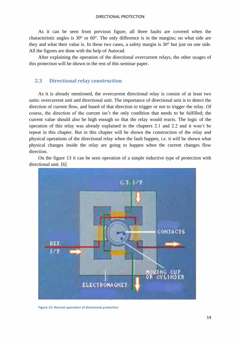
On the figure 13 it can be seen operation of a simple inductive type of protection with
directional unit. [6]
Figure 13: Normal operation of directional protection
DIRECTIONAL PROTECTION
15
A red colour is a winding where information is obtained about the reference value (voltage or
current), and a green colour indicates a winding with information about the current, which is
obtained through a current transformer of a protected device. There is also a cylinder with
two contacts, by which the relay is actuated or not. In normal operation (no fault), the
direction of reference and current value is shown with orange arrows. The cylinder is in the
position as it can be seen in Figure 13; the upper contact is closed and prevents further
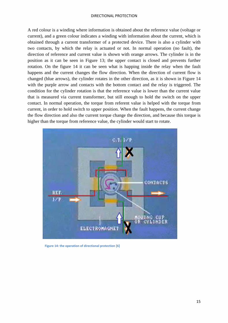
rotation. On the figure 14 it can be seen what is happing inside the relay when the fault
happens and the current changes the flow direction. When the direction of current flow is
changed (blue arrows), the cylinder rotates in the other direction, as it is shown in Figure 14
with the purple arrow and contacts with the bottom contact and the relay is triggered. The
condition for the cylinder rotation is that the reference value is lower than the current value
that is measured via current transformer, but still enough to hold the switch on the upper
contact. In normal operation, the torque from referent value is helped with the torque from
current, in order to hold switch to upper position. When the fault happens, the current change
the flow direction and also the current torque change the direction, and because this torque is
higher than the torque from reference value, the cylinder would start to rotate.
Figure 14: the operation of directional protection [6]
DIRECTIONAL PROTECTION
16
3 Protection of parallel distribution lines
The usage of multiple lines improves the availability of power, i.e. using multiple lines
in parallel allows more power to be conveyed to a given location. Two parallel connected
lines are the simplest and most frequently encountered example of a closed ring. The
protection system must be designed in such a way that when a fault is on one line, the other
distribution line should continue with its normal operation. For better explanation why the
directional protection is necessary in this case, the protection system will be firstly explained
just with regular overcurrent relays and it will be explained why it is not good solution and
why directional protection must be used if we want to have good selectivity of relay
protection.
As it is already mentioned, the simple system with two parallel lines will be observed.
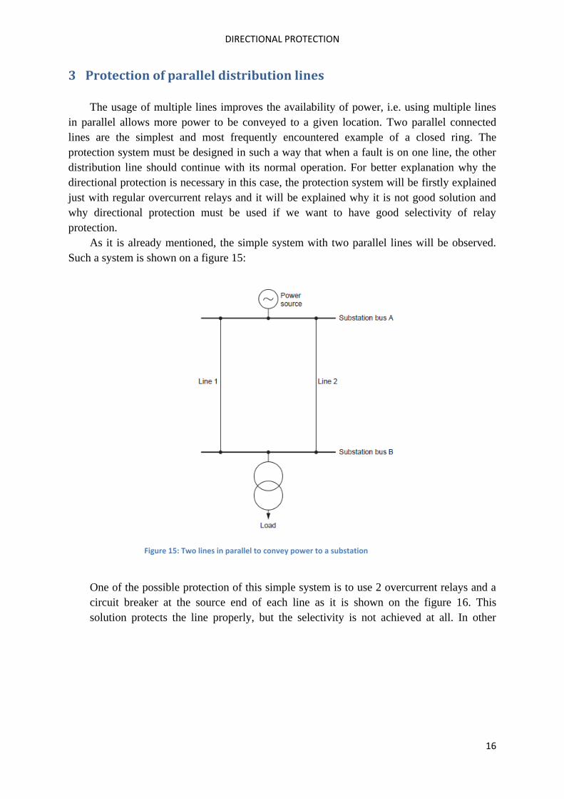
Such a system is shown on a figure 15:
Figure 15: Two lines in parallel to convey power to a substation
One of the possible protection of this simple system is to use 2 overcurrent relays and a
circuit breaker at the source end of each line as it is shown on the figure 16. This
solution protects the line properly, but the selectivity is not achieved at all. In other
DIRECTIONAL PROTECTION
17
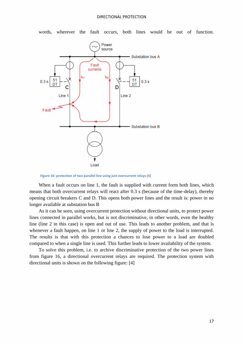
words, wherever the fault occurs, both lines would be out of function.
Figure 16: protection of two parallel line using just overcurrent relays [4]
When a fault occurs on line 1, the fault is supplied with current form both lines, which
means that both overcurrent relays will react after 0.3 s (because of the time-delay), thereby
opening circuit breakers C and D. This opens both power lines and the result is: power in no
longer available at substation bus B
As it can be seen, using overcurrent protection without directional units, to protect power
lines connected in parallel works, but is not discriminative, in other words, even the healthy
line (line 2 in this case) is open and out of use. This leads to another problem, and that is
whenever a fault happen, on line 1 or line 2, the supply of power to the load is interrupted.
The results is that with this protection a chances to lose power to a load are doubled
compared to when a single line is used. This further leads to lower availability of the system.
To solve this problem, i.e. to archive discriminative protection of the two power lines
from figure 16, a directional overcurrent relays are required. The protection system with
directional units is shown on the following figure: [4]
DIRECTIONAL PROTECTION
18
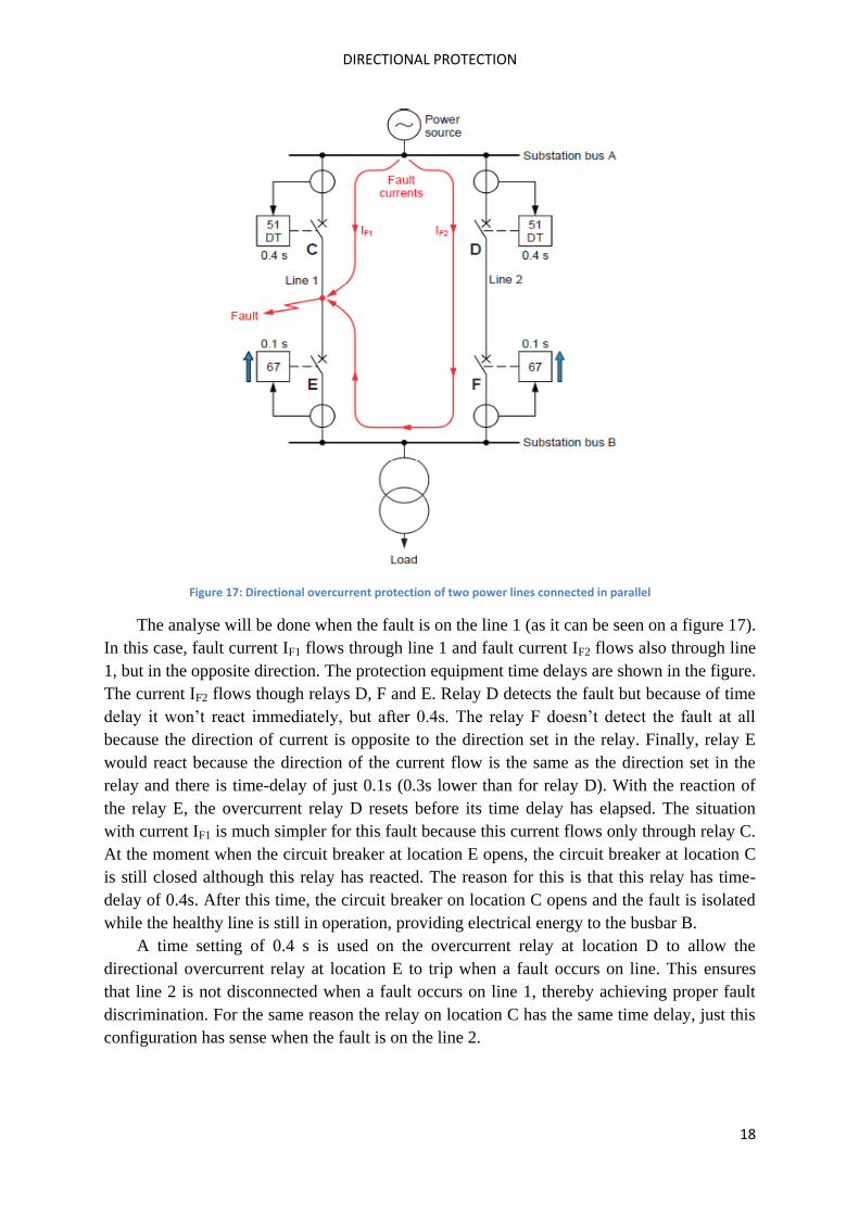
Figure 17: Directional overcurrent protection of two power lines connected in parallel
The analyse will be done when the fault is on the line 1 (as it can be seen on a figure 17).
In this case, fault current IF1 flows through line 1 and fault current IF2 flows also through line
1, but in the opposite direction. The protection equipment time delays are shown in the figure.
The current IF2 flows though relays D, F and E. Relay D detects the fault but because of time
delay it won’t react immediately, but after 0.4s. The relay F doesn’t detect the fault at all
because the direction of current is opposite to the direction set in the relay. Finally, relay E
would react because the direction of the current flow is the same as the direction set in the
relay and there is time-delay of just 0.1s (0.3s lower than for relay D). With the reaction of
the relay E, the overcurrent relay D resets before its time delay has elapsed. The situation
with current IF1 is much simpler for this fault because this current flows only through relay C.
At the moment when the circuit breaker at location E opens, the circuit breaker at location C
is still closed although this relay has reacted. The reason for this is that this relay has time-
delay of 0.4s. After this time, the circuit breaker on location C opens and the fault is isolated
while the healthy line is still in operation, providing electrical energy to the busbar B.
A time setting of 0.4 s is used on the overcurrent relay at location D to allow the
directional overcurrent relay at location E to trip when a fault occurs on line. This ensures
that line 2 is not disconnected when a fault occurs on line 1, thereby achieving proper fault
discrimination. For the same reason the relay on location C has the same time delay, just this
configuration has sense when the fault is on the line 2.
DIRECTIONAL PROTECTION
19
4 Protection of closed loop
The principle of protecting the closed loop is the same as the principle of protecting the
system with two parallel lines. The only difference is that in the closed loop there are much
more lines, which means more relays and the time-delay of individual relays is much higher.
Depending on the application, longer fault clearing times may or may not be acceptable for
various reasons. On the next figure, one of the possible solutions for protecting the closed
loop system is shown: [1]
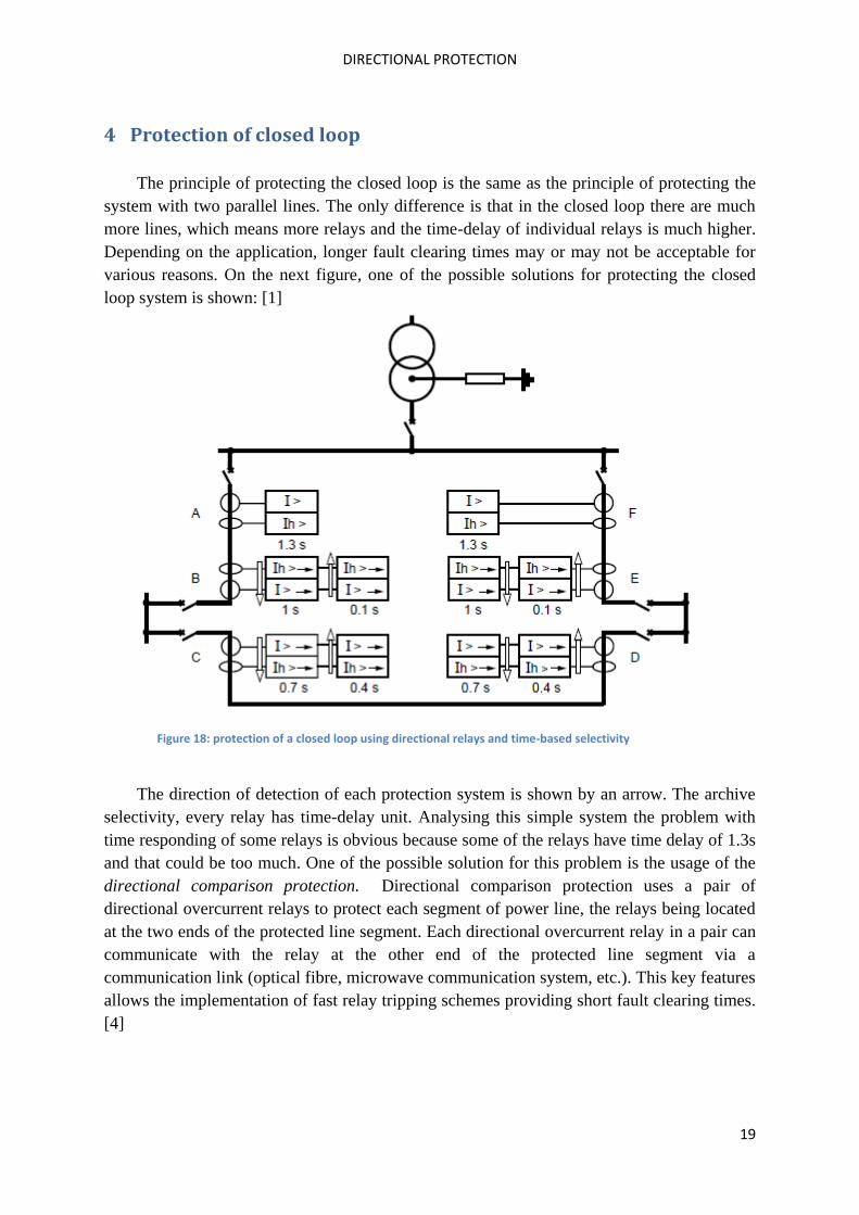
Figure 18: protection of a closed loop using directional relays and time-based selectivity
The direction of detection of each protection system is shown by an arrow. The archive
selectivity, every relay has time-delay unit. Analysing this simple system the problem with
time responding of some relays is obvious because some of the relays have time delay of 1.3s
and that could be too much. One of the possible solution for this problem is the usage of the
directional comparison protection. Directional comparison protection uses a pair of
directional overcurrent relays to protect each segment of power line, the relays being located
at the two ends of the protected line segment. Each directional overcurrent relay in a pair can
communicate with the relay at the other end of the protected line segment via a
communication link (optical fibre, microwave communication system, etc.). This key features
allows the implementation of fast relay tripping schemes providing short fault clearing times.
[4]
DIRECTIONAL PROTECTION
20
5 Earth fault directional protection
There are two types of ground faults: single line ground faults (SLG fault) and line-to-
line ground fault (LLG fault). The ground fault is different from other types of short circuit
because it has a zero sequence of a current I0. Since in normal operations this current doesn’t
exist, the relays for detecting ground fault measure the component I0=(Ia+Ib+Ic)/3 and
declaring the fault of I0 exceeds a threshold.
However, in a system with multiple sources or parallel paths, it is required that earth
fault relays have directional unit. The reference phasor is sometimes called as polarizing
quantity or residual quantity. Also, both voltage and current polarizing signals are used with
ground fault relaying.
Before explaining these two polarizing signals, the term residual variable should be
explained. For example, if the zero sequence variable Fh is defined as: [1]
1( 1 2 3)
3hF F F F (1)
The residual variable is:
1 2 3Fr F F F (2)
and it is three times greater than the zero sequence variable.
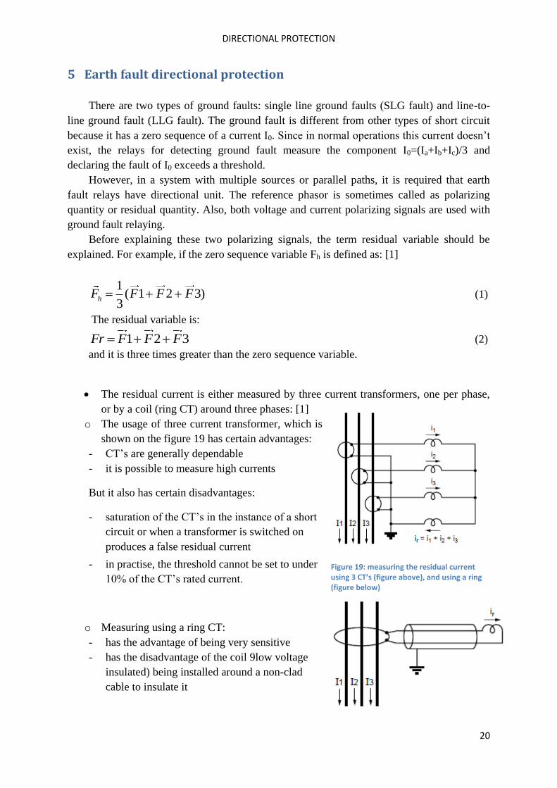
The residual current is either measured by three current transformers, one per phase,
or by a coil (ring CT) around three phases: [1]
o The usage of three current transformer, which is
shown on the figure 19 has certain advantages:
- CT’s are generally dependable
- it is possible to measure high currents
But it also has certain disadvantages:
- saturation of the CT’s in the instance of a short
circuit or when a transformer is switched on
produces a false residual current
- in practise, the threshold cannot be set to under
10% of the CT’s rated current.
o Measuring using a ring CT:
- has the advantage of being very sensitive
- has the disadvantage of the coil 9low voltage
insulated) being installed around a non-clad
cable to insulate it
Figure 19: measuring the residual current using 3 CT’s (figure above), and using a ring (figure below)
DIRECTIONAL PROTECTION
21
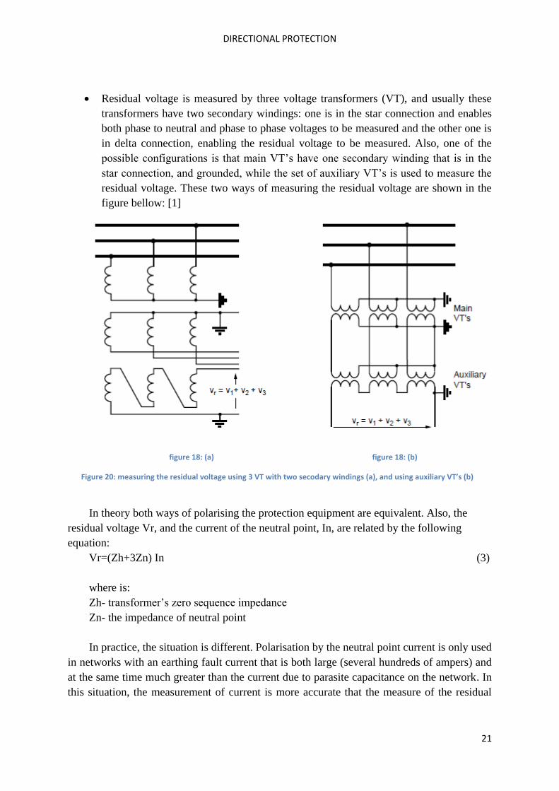
Residual voltage is measured by three voltage transformers (VT), and usually these
transformers have two secondary windings: one is in the star connection and enables
both phase to neutral and phase to phase voltages to be measured and the other one is
in delta connection, enabling the residual voltage to be measured. Also, one of the
possible configurations is that main VT’s have one secondary winding that is in the
star connection, and grounded, while the set of auxiliary VT’s is used to measure the
residual voltage. These two ways of measuring the residual voltage are shown in the
figure bellow: [1]
figure 18: (a) figure 18: (b)
Figure 20: measuring the residual voltage using 3 VT with two secodary windings (a), and using auxiliary VT’s (b)
In theory both ways of polarising the protection equipment are equivalent. Also, the
residual voltage Vr, and the current of the neutral point, In, are related by the following
equation:
Vr=(Zh+3Zn) In (3)
where is:
Zh- transformer’s zero sequence impedance
Zn- the impedance of neutral point
In practice, the situation is different. Polarisation by the neutral point current is only used
in networks with an earthing fault current that is both large (several hundreds of ampers) and
at the same time much greater than the current due to parasite capacitance on the network. In
this situation, the measurement of current is more accurate that the measure of the residual
DIRECTIONAL PROTECTION
22
voltage which has a small value. These situations are common in the substations that are near
to the neutral earthing connection.
The detection of the current flow direction is performed in the same way as it was
explained in the chapter 2.1.
6 Power relays
These relays won’t be explained as the previous situations, using the logic “what would
happen if this relay is just regular power relay, without directional unit”. The reason for this
is that power relays are naturally directional, i.e. every power relay has directional unit. This
type of protection equipment often uses a dual wattmeter method to measure the active and
reactive power.
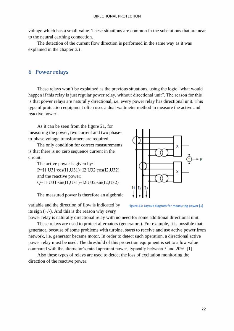
As it can be seen from the figure 21, for
measuring the power, two current and two phase-
to-phase voltage transformers are required.
The only condition for correct measurements
is that there is no zero sequence current in the
circuit.
The active power is given by:
P=I1∙U31∙cos(I1,U31)+I2∙U32∙cos(I2,U32)
and the reactive power:
Q=I1∙U31∙sin(I1,U31)+I2∙U32∙sin(I2,U32)
The measured power is therefore an algebraic
variable and the direction of flow is indicated by
its sign (+/-). And this is the reason why every
power relay is naturally directional relay with no need for some additional directional unit.
These relays are used to protect alternators (generators). For example, it is possible that
generator, because of some problems with turbine, starts to receive and use active power from
network, i.e. generator became motor. In order to detect such operation, a directional active
power relay must be used. The threshold of this protection equipment is set to a low value
compared with the alternator’s rated apparent power, typically between 5 and 20%. [1]
Also these types of relays are used to detect the loss of excitation monitoring the
direction of the reactive power.
Figure 21: Layout diagram for measuring power [1]
DIRECTIONAL PROTECTION
23
7 Conclusion
In modern distribution networks, the usage of directional protection is essential in order
to achieve satisfactory selectivity. Generally speaking, there are three types of directional
protection: phase directional protection, earth fault directional protection and active and
reactive directional power protection. But regardless of type, the operation principle of this
protection is the same. To determine the direction of the fault, the protection equipment
measures the phase displacement between the current and the polarization voltage and based
on this phase displacement the protection “decides” should it react or not. Also, one of the
most important parts of the direction protection is so-called characteristic angle. If the
polarisation variable is not in the axis of symmetry of the wished relay’s action, it’s necessary
to re-phase it by adjusting this angle. The typical values of this angle are 30°, 45° or 60°.
To achieve selectivity, this protection must be used in the following situations: in a
system with several sources, in closed-loop system or system with parallel cables, in isolated
neutral systems for the feedback of capacitive current and to detect an abnormal direction of
flow of active or reactive power. Also, the relays that are used for this protection almost
always have a time-delay unit, especially in distribution meshed grid. And this necessity of
time-delay unit in every directional relay is the biggest problem of directional and generally
of the overcurrent protection at all, because in meshed grids time relays could have
unacceptably large time-delay and in that situation some other protection must be used. But
beside this disadvantage, the directional protection is used more and more in modern
distribution system, especially because the number of power sources that submit electrical
energy directly in distribution system is increasing.
DIRECTIONAL PROTECTION
24
References:
[1] Pierre BERTRAND, “Directional protection equipment”, march 1998
[2] John Horak, “Directional Overcurrent Relaying (67) Concepts”
[3] Module 5: Directional Overcurrent Protection; lecture 18: Directional Overcurrent
Relaying
[4] Electricity and New Energy, Directional Protection, Courseware Sample
[5] Abdelhay A. Sallam, OM P. Malik, “Electric Distribution System”, chapter 5.5
[6] Gašper Lenassi, „Smerna zaščita“-seminarska naloga
QUESTIONS
1. In what conditions is it necessary to use directional protection?
In a system with several sources, in closed loop or parallel-cables system, in isolated
neutral systems for the feedback of capacitive current and to detect an abnormal direction
of flow of active or reactive power.
2. How does directional protection determine the direction of current, keeping in
mind that distribution network is network with alternative current?
To determine the direction of the fault, the protection equipment measures the phase
displacement between the current and the polarization voltage and based on this phase
displacement the protection “decides” should it react or not.
3. What is characteristic angle, and what are usual values for this angle?
Characteristic angle is the angle between polarizing vector and a line perpendicular to the
boundary line. If the polarisation variable is not in the axis of symmetry of the wished
relay’s action, it’s necessary to re-phase it by adjusting the characteristic angle. Typical
values for this angle are: θ=30°, θ=45° and θ=60°.
4. What is the biggest disadvantage of directional protection?
The relays that are used for directional protection usually have time-delay unit. In big,
meshed grids, time-delay for certain relays could be higher than the value that is allowed,
and because of this some other protection should be used for this kind of networks.
DIRECTIONAL PROTECTION
25
EXAMPLE:
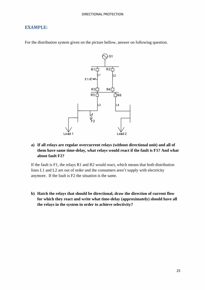
For the distribution system given on the picture bellow, answer on following question.
a) If all relays are regular overcurrent relays (without directional unit) and all of
them have same time-delay, what relays would react if the fault is F1? And what
about fault F2?
If the fault is F1, the relays R1 and R2 would react, which means that both distribution
lines L1 and L2 are out of order and the consumers aren’t supply with electricity
anymore. If the fault is F2 the situation is the same.
b) Hatch the relays that should be directional, draw the direction of current flow
for which they react and write what time-delay (approximately) should have all
the relays in the system in order to achieve selectivity?
DIRECTIONAL PROTECTION
26
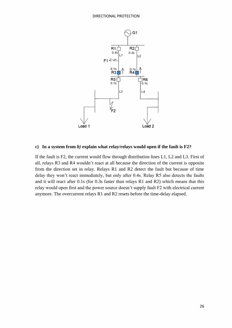
c) In a system from b) explain what relay/relays would open if the fault is F2?
If the fault is F2, the current would flow through distribution lines L1, L2 and L3. First of
all, relays R3 and R4 wouldn’t react at all because the direction of the current is opposite
from the direction set in relay. Relays R1 and R2 detect the fault but because of time
delay they won’t react immediately, but only after 0.4s. Relay R5 also detects the faults
and it will react after 0.1s (for 0.3s faster than relays R1 and R2) which means that this
relay would open first and the power source doesn’t supply fault F2 with electrical current
anymore. The overcurrent relays R1 and R2 resets before the time-delay elapsed.

DIRECTIONAL PROTECTION
27


![RAZPRŠENI VIRI ELEKTRIČNE ENERGIJE IN - Domovlrf.fe.uni-lj.si/e_rio/Seminarji1516/... · E energija [J] I tok [A] RIO 2015/16 JERIHA JAN 4 1. Uvod ... Geotermalna energija [7],](https://img.pdfslide.net/doc/110x75/5a7934417f8b9ae93a8bc815/razprseni-viri-elektricne-energije-in-energija-j-i-tok-a-rio-201516-jeriha.jpg)