Embed Size (px)
Citation preview
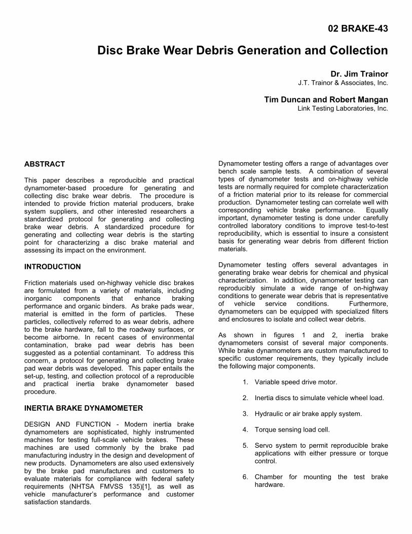
02 BRAKE-43
Disc Brake Wear Debris Generation and Collection
Dr. Jim Trainor J.T. Trainor & Associates, Inc.
Tim Duncan and Robert Mangan Link Testing Laboratories, Inc.
ABSTRACT
This paper describes a reproducible and practical dynamometer-based procedure for generating and collecting disc brake wear debris. The procedure is intended to provide friction material producers, brake system suppliers, and other interested researchers a standardized protocol for generating and collecting brake wear debris. A standardized procedure for generating and collecting wear debris is the starting point for characterizing a disc brake material and assessing its impact on the environment.
INTRODUCTION
Friction materials used on-highway vehicle disc brakes are formulated from a variety of materials, including inorganic components that enhance braking performance and organic binders. As brake pads wear, material is emitted in the form of particles. These particles, collectively referred to as wear debris, adhere to the brake hardware, fall to the roadway surfaces, or become airborne. In recent cases of environmental contamination, brake pad wear debris has been suggested as a potential contaminant. To address this concern, a protocol for generating and collecting brake pad wear debris was developed. This paper entails the set-up, testing, and collection protocol of a reproducible and practical inertia brake dynamometer based procedure.
INERTIA BRAKE DYNAMOMETER
DESIGN AND FUNCTION - Modern inertia brake dynamometers are sophisticated, highly instrumented machines for testing full-scale vehicle brakes. These machines are used commonly by the brake pad manufacturing industry in the design and development of new products. Dynamometers are also used extensively by the brake pad manufactures and customers to evaluate materials for compliance with federal safety requirements (NHTSA FMVSS 135)[1], as well as vehicle manufacturer’s performance and customer satisfaction standards.
Dynamometer testing offers a range of advantages over bench scale sample tests. A combination of several types of dynamometer tests and on-highway vehicle tests are normally required for complete characterization of a friction material prior to its release for commercial production. Dynamometer testing can correlate well with corresponding vehicle brake performance. Equally important, dynamometer testing is done under carefully controlled laboratory conditions to improve test-to-test reproducibility, which is essential to insure a consistent basis for generating wear debris from different friction materials.
Dynamometer testing offers several advantages in generating brake wear debris for chemical and physical characterization. In addition, dynamometer testing can reproducibly simulate a wide range of on-highway conditions to generate wear debris that is representative of vehicle service conditions. Furthermore, dynamometers can be equipped with specialized filters and enclosures to isolate and collect wear debris.
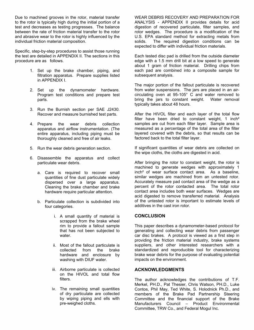
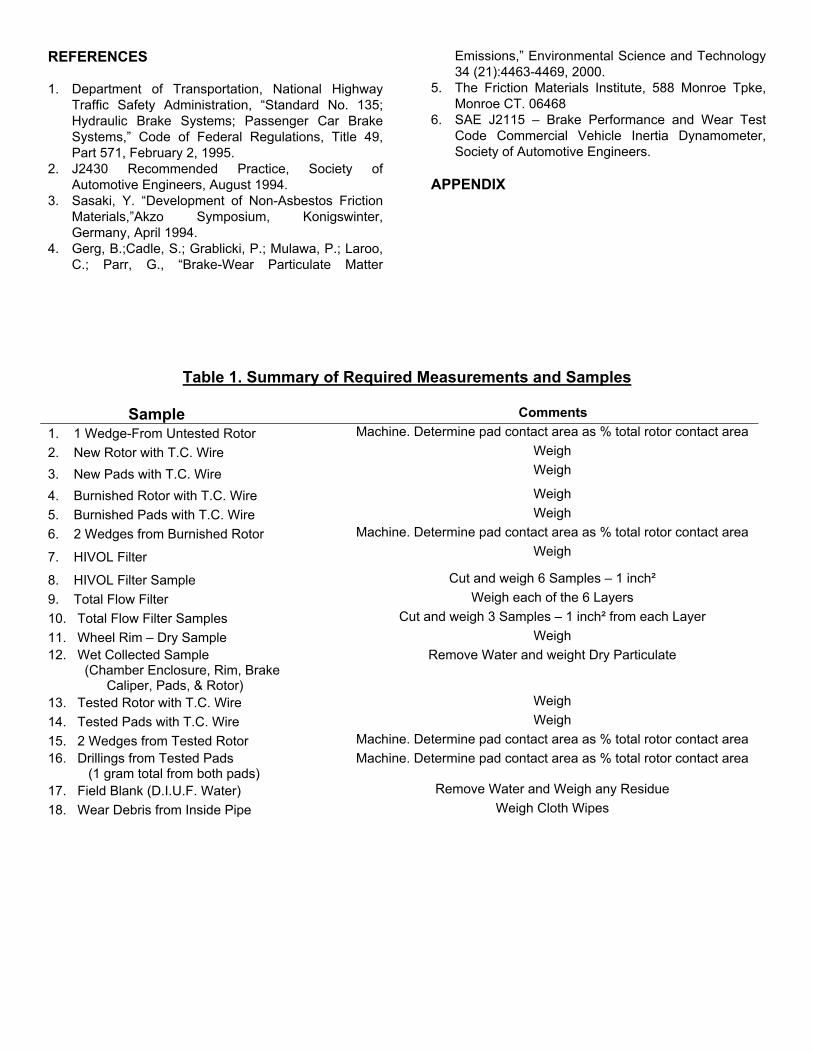
As shown in figures 1 and 2, inertia brake dynamometers consist of several major components. While brake dynamometers are custom manufactured to specific customer requirements, they typically include the following major components.
1. Variable speed drive motor.
2. Inertia discs to simulate vehicle wheel load.
3. Hydraulic or air brake apply system.
4. Torque sensing load cell.
5. Servo system to permit reproducible brake applications with either pressure or torque control.
6. Chamber for mounting the test brake hardware.
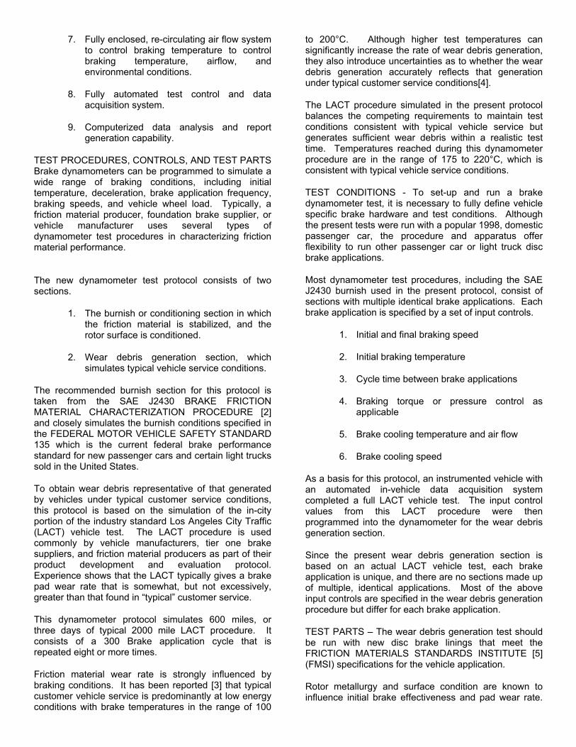
7. Fully enclosed, re-circulating air flow system to control braking temperature to control braking temperature, airflow, and environmental conditions.
8. Fully automated test control and data acquisition system.
9. Computerized data analysis and report generation capability.
TEST PROCEDURES, CONTROLS, AND TEST PARTS Brake dynamometers can be programmed to simulate a wide range of braking conditions, including initial temperature, deceleration, brake application frequency, braking speeds, and vehicle wheel load. Typically, a friction material producer, foundation brake supplier, or vehicle manufacturer uses several types of dynamometer test procedures in characterizing friction material performance.
The new dynamometer test protocol consists of two sections.
1. The burnish or conditioning section in which the friction material is stabilized, and the rotor surface is conditioned.
2. Wear debris generation section, which simulates typical vehicle service conditions.
The recommended burnish section for this protocol is taken from the SAE J2430 BRAKE FRICTION MATERIAL CHARACTERIZATION PROCEDURE [2] and closely simulates the burnish conditions specified in the FEDERAL MOTOR VEHICLE SAFETY STANDARD 135 which is the current federal brake performance standard for new passenger cars and certain light trucks sold in the United States.
To obtain wear debris representative of that generated by vehicles under typical customer service conditions, this protocol is based on the simulation of the in-city portion of the industry standard Los Angeles City Traffic (LACT) vehicle test. The LACT procedure is used commonly by vehicle manufacturers, tier one brake suppliers, and friction material producers as part of their product development and evaluation protocol. Experience shows that the LACT typically gives a brake pad wear rate that is somewhat, but not excessively, greater than that found in “typical” customer service.
This dynamometer protocol simulates 600 miles, or three days of typical 2000 mile LACT procedure. It consists of a 300 Brake application cycle that is repeated eight or more times.
Friction material wear rate is strongly influenced by braking conditions. It has been reported [3] that typical customer vehicle service is predominantly at low energy conditions with brake temperatures in the range of 100
to 200°C. Although higher test temperatures can significantly increase the rate of wear debris generation, they also introduce uncertainties as to whether the wear debris generation accurately reflects that generation under typical customer service conditions[4].
The LACT procedure simulated in the present protocol balances the competing requirements to maintain test conditions consistent with typical vehicle service but generates sufficient wear debris within a realistic test time. Temperatures reached during this dynamometer procedure are in the range of 175 to 220°C, which is consistent with typical vehicle service conditions.
TEST CONDITIONS - To set-up and run a brake dynamometer test, it is necessary to fully define vehicle specific brake hardware and test conditions. Although the present tests were run with a popular 1998, domestic passenger car, the procedure and apparatus offer flexibility to run other passenger car or light truck disc brake applications.
Most dynamometer test procedures, including the SAE J2430 burnish used in the present protocol, consist of sections with multiple identical brake applications. Each brake application is specified by a set of input controls.
1. Initial and final braking speed
2. Initial braking temperature
3. Cycle time between brake applications
4. Braking torque or pressure control as applicable
5. Brake cooling temperature and air flow
6. Brake cooling speed
As a basis for this protocol, an instrumented vehicle with an automated in-vehicle data acquisition system completed a full LACT vehicle test. The input control values from this LACT procedure were then programmed into the dynamometer for the wear debris generation section.
Since the present wear debris generation section is based on an actual LACT vehicle test, each brake application is unique, and there are no sections made up of multiple, identical applications. Most of the above input controls are specified in the wear debris generation procedure but differ for each brake application.
TEST PARTS – The wear debris generation test should be run with new disc brake linings that meet the FRICTION MATERIALS STANDARDS INSTITUTE [5] (FMSI) specifications for the vehicle application.
Rotor metallurgy and surface condition are known to influence initial brake effectiveness and pad wear rate.
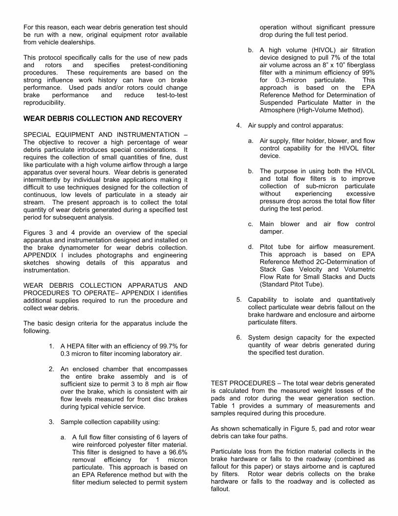
For this reason, each wear debris generation test should be run with a new, original equipment rotor available from vehicle dealerships.
This protocol specifically calls for the use of new pads and rotors and specifies pretest-conditioning procedures. These requirements are based on the strong influence work history can have on brake performance. Used pads and/or rotors could change brake performance and reduce test-to-test reproducibility.
WEAR DEBRIS COLLECTION AND RECOVERY SPECIAL EQUIPMENT AND INSTRUMENTATION – The objective to recover a high percentage of wear debris particulate introduces special considerations. It requires the collection of small quantities of fine, dust like particulate with a high volume airflow through a large apparatus over several hours. Wear debris is generated intermittently by individual brake applications making it difficult to use techniques designed for the collection of continuous, low levels of particulate in a steady air stream. The present approach is to collect the total quantity of wear debris generated during a specified test period for subsequent analysis.
Figures 3 and 4 provide an overview of the special apparatus and instrumentation designed and installed on the brake dynamometer for wear debris collection. APPENDIX I includes photographs and engineering sketches showing details of this apparatus and instrumentation.
WEAR DEBRIS COLLECTION APPARATUS AND PROCEDURES TO OPERATE– APPENDIX I identifies additional supplies required to run the procedure and collect wear debris.
The basic design criteria for the apparatus include the following.
1. A HEPA filter with an efficiency of 99.7% for 0.3 micron to filter incoming laboratory air.
2. An enclosed chamber that encompasses the entire brake assembly and is of sufficient size to permit 3 to 8 mph air flow over the brake, which is consistent with air flow levels measured for front disc brakes during typical vehicle service.
3. Sample collection capability using:
a. A full flow filter consisting of 6 layers of wire reinforced polyester filter material. This filter is designed to have a 96.6% removal efficiency for 1 micron particulate. This approach is based on an EPA Reference method but with the filter medium selected to permit system
operation without significant pressure drop during the full test period.
b. A high volume (HIVOL) air filtration device designed to pull 7% of the total air volume across an 8” x 10” fiberglass filter with a minimum efficiency of 99% for 0.3-micron particulate. This approach is based on the EPA Reference Method for Determination of Suspended Particulate Matter in the Atmosphere (High-Volume Method).
4. Air supply and control apparatus:
a. Air supply, filter holder, blower, and flow control capability for the HIVOL filter device.
b. The purpose in using both the HIVOL and total flow filters is to improve collection of sub-micron particulate without experiencing excessive pressure drop across the total flow filter during the test period.
c. Main blower and air flow control damper.
d. Pitot tube for airflow measurement. This approach is based on EPA Reference Method 2C-Determination of Stack Gas Velocity and Volumetric Flow Rate for Small Stacks and Ducts (Standard Pitot Tube).
5. Capability to isolate and quantitatively collect particulate wear debris fallout on the brake hardware and enclosure and airborne particulate filters.
6. System design capacity for the expected quantity of wear debris generated during the specified test duration.
TEST PROCEDURES – The total wear debris generated is calculated from the measured weight losses of the pads and rotor during the wear generation section. Table 1 provides a summary of measurements and samples required during this procedure.
As shown schematically in Figure 5, pad and rotor wear debris can take four paths.
Particulate loss from the friction material collects in the brake hardware or falls to the roadway (combined as fallout for this paper) or stays airborne and is captured by filters. Rotor wear debris collects on the brake hardware or falls to the roadway and is collected as fallout.
Due to machined grooves in the rotor, material transfer to the rotor is typically high during the initial portion of a test and decreases as testing progresses. The balance between the rate of friction material transfer to the rotor and abrasive wear to the rotor is highly influenced by the individual friction material composition.
Specific, step-by-step procedures to assist those running the test are detailed in APPENDIX II. The sections in this procedure are as follows.
1. Set up the brake chamber, piping, and filtration apparatus. Prepare supplies listed in APPENDIX I.
2. Set up the dynamometer hardware. Program test conditions and prepare test parts.
3. Run the Burnish section per SAE J2430. Recover and measure burnished test parts.
4. Prepare the wear debris collection apparatus and airflow instrumentation. (The entire apparatus, including piping must be thoroughly cleaned and free of air leaks.
5. Run the wear debris generation section.
6. Disassemble the apparatus and collect particulate wear debris.
a. Care is required to recover small quantities of fine dust particulate widely dispersed over a large apparatus. Cleaning the brake chamber and brake hardware require particular attention.
b. Particulate collection is subdivided into four categories.
i. A small quantity of material is scrapped from the brake wheel rim to provide a fallout sample that has not been subjected to water.
ii. Most of the fallout particulate is collected from the brake hardware and enclosure by washing with DIUF water.
iii. Airborne particulate is collected on the HIVOL and total flow filters.
iv. The remaining small quantities of dry particulate are collected by wiping piping and ells with pre-weighed cloths.
WEAR DEBRIS RECOVERY AND PREPARATION FOR ANALYSIS - APPENDIX II provides details for acid digestion of recovered particulate, filter samples, and rotor wedges. The procedure is a modification of the U.S. EPA standard method for extracting metals from solids. The required digestion conditions can be expected to differ with individual friction materials.
Each tested disc pad is drilled from the outside diameter edge with a 1.5 mm drill bit at a low speed to generate about 1 gram of friction material. Drilling chips from each pad are combined into a composite sample for subsequent analysis.
The major portion of the fallout particulate is recovered from water suspensions. The jars are placed in an air-circulating oven at 95-105° C and water removed to bring the jars to constant weight. Water removal typically takes about 48 hours.
After the HIVOL filter and each layer of the total flow filter have been dried to constant weight, 1 inch² samples are cut from each filter layer. Sample area is measured as a percentage of the total area of the filter layered covered with the debris, so that results can be factored back to the total filter layer.
If significant quantities of wear debris are collected on the wipe cloths, the cloths are digested in acid.
After bringing the rotor to constant weight, the rotor is machined to generate wedges with approximately 1 inch² of wear surface contact area. As a baseline, similar wedges are machined from an untested rotor. Accurately measure pad contact area of the wedge as a percent of the rotor contacted area. The total rotor contact area includes both wear surfaces. Wedges are acid digested to remove transferred material. Analysis of the untested rotor is important to estimate levels of additives in the cast iron rotor.
CONCLUSION
This paper describes a dynamometer-based protocol for generating and collecting wear debris from passenger car disc brakes. A protocol is viewed as a first step in providing the friction material industry, brake systems suppliers, and other interested researchers with a standardized and reproducible tool for characterizing brake wear debris for the purpose of evaluating potential impacts on the environment.
ACKNOWLEDGMENTS
The author acknowledges the contributions of T.F. Merkel, PH.D., Pat Thesier, Chris Watson, PH.D., Luke Contos, Phil May, Ted White, S. Holodnick Ph.D., and members of the Brake Pad Partnership Steering Committee and the financial support of the Brake Manufacturers Council – Product Environmental Committee, TRW Co., and Federal Mogul Inc.
REFERENCES
1. Department of Transportation, National Highway Traffic Safety Administration, “Standard No. 135; Hydraulic Brake Systems; Passenger Car Brake Systems,” Code of Federal Regulations, Title 49, Part 571, February 2, 1995.
2. J2430 Recommended Practice, Society of Automotive Engineers, August 1994.
3. Sasaki, Y. “Development of Non-Asbestos Friction Materials,”Akzo Symposium, Konigswinter, Germany, April 1994.
4. Gerg, B.;Cadle, S.; Grablicki, P.; Mulawa, P.; Laroo, C.; Parr, G., “Brake-Wear Particulate Matter
Emissions,” Environmental Science and Technology 34 (21):4463-4469, 2000.
5. The Friction Materials Institute, 588 Monroe Tpke, Monroe CT. 06468
6. SAE J2115 – Brake Performance and Wear Test Code Commercial Vehicle Inertia Dynamometer, Society of Automotive Engineers.
APPENDIX
Table 1. Summary of Required Measurements and Samples
Sample Comments 1. 1 Wedge-From Untested Rotor Machine. Determine pad contact area as % total rotor contact area 2. New Rotor with T.C. Wire Weigh
3. New Pads with T.C. Wire Weigh
4. Burnished Rotor with T.C. Wire Weigh 5. Burnished Pads with T.C. Wire Weigh 6. 2 Wedges from Burnished Rotor Machine. Determine pad contact area as % total rotor contact area
7. HIVOL Filter Weigh
8. HIVOL Filter Sample Cut and weigh 6 Samples – 1 inch² 9. Total Flow Filter Weigh each of the 6 Layers 10. Total Flow Filter Samples Cut and weigh 3 Samples – 1 inch² from each Layer 11. Wheel Rim – Dry Sample Weigh 12. Wet Collected Sample (Chamber Enclosure, Rim, Brake Caliper, Pads, & Rotor)
Remove Water and weight Dry Particulate
13. Tested Rotor with T.C. Wire Weigh 14. Tested Pads with T.C. Wire Weigh 15. 2 Wedges from Tested Rotor Machine. Determine pad contact area as % total rotor contact area 16. Drillings from Tested Pads (1 gram total from both pads)
Machine. Determine pad contact area as % total rotor contact area
17. Field Blank (D.I.U.F. Water) Remove Water and Weigh any Residue 18. Wear Debris from Inside Pipe Weigh Cloth Wipes
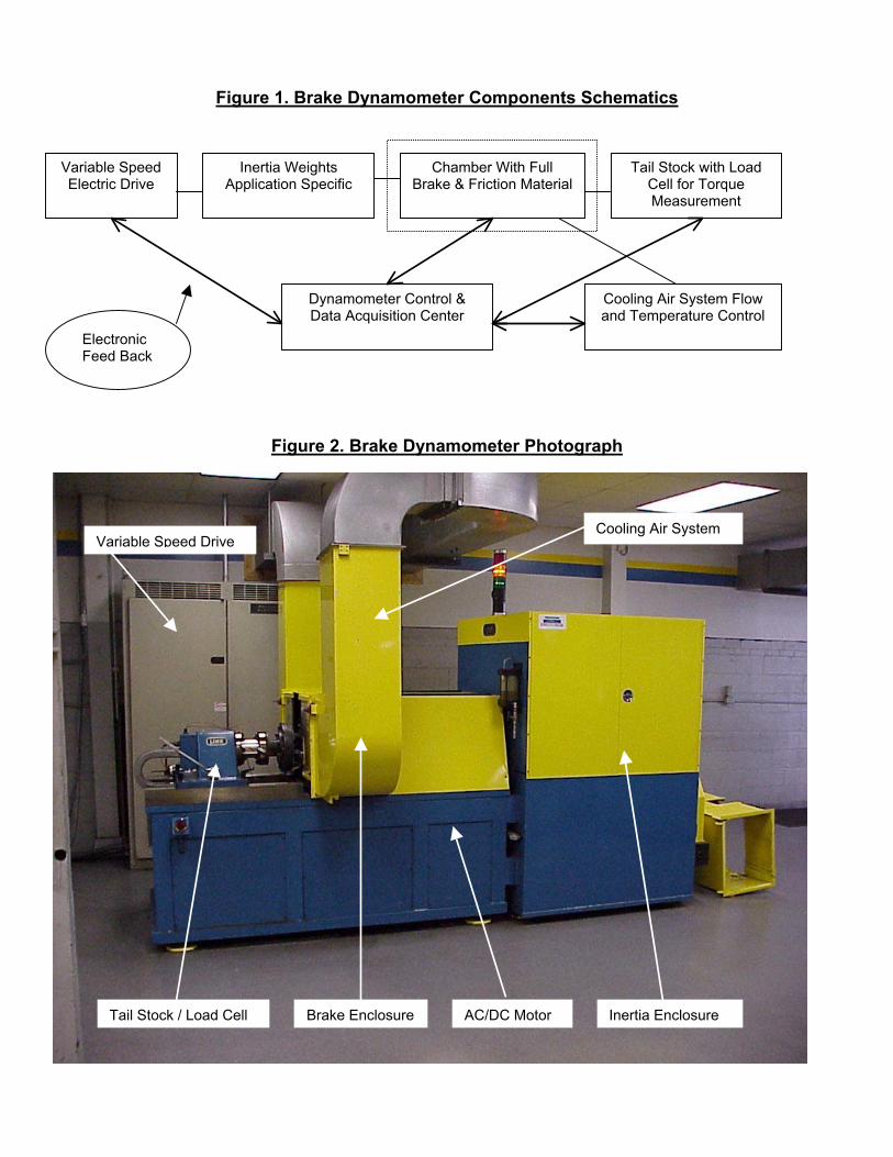
Figure 1. Brake Dynamometer Components Schematics
Figure 2. Brake Dynamometer Photograph
Variable Speed Electric Drive
Inertia Weights Application Specific
Chamber With Full Brake & Friction Material
Tail Stock with Load Cell for Torque Measurement
Dynamometer Control & Data Acquisition Center
Cooling Air System Flow and Temperature Control
Electronic Feed Back
Variable Speed Drive
Tail Stock / Load Cell Brake Enclosure AC/DC Motor Inertia Enclosure
Cooling Air System
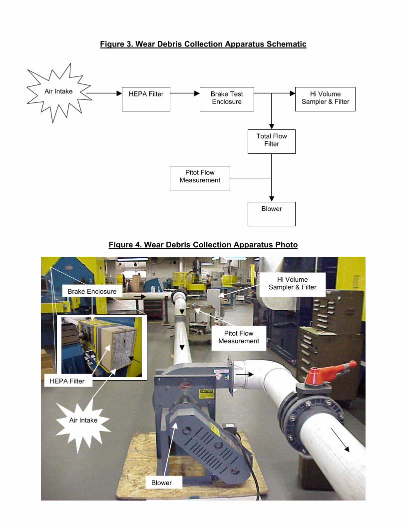
Figure 3. Wear Debris Collection Apparatus Schematic
Figure 4. Wear Debris Collection Apparatus Photo
HEPA FilterAir Intake Brake Test Enclosure
Hi Volume Sampler & Filter
Total Flow Filter
Blower
Pitot Flow Measurement
Air Intake
HEPA Filter
Brake Enclosure
Blower
Pitot Flow Measurement
Hi Volume Sampler & Filter
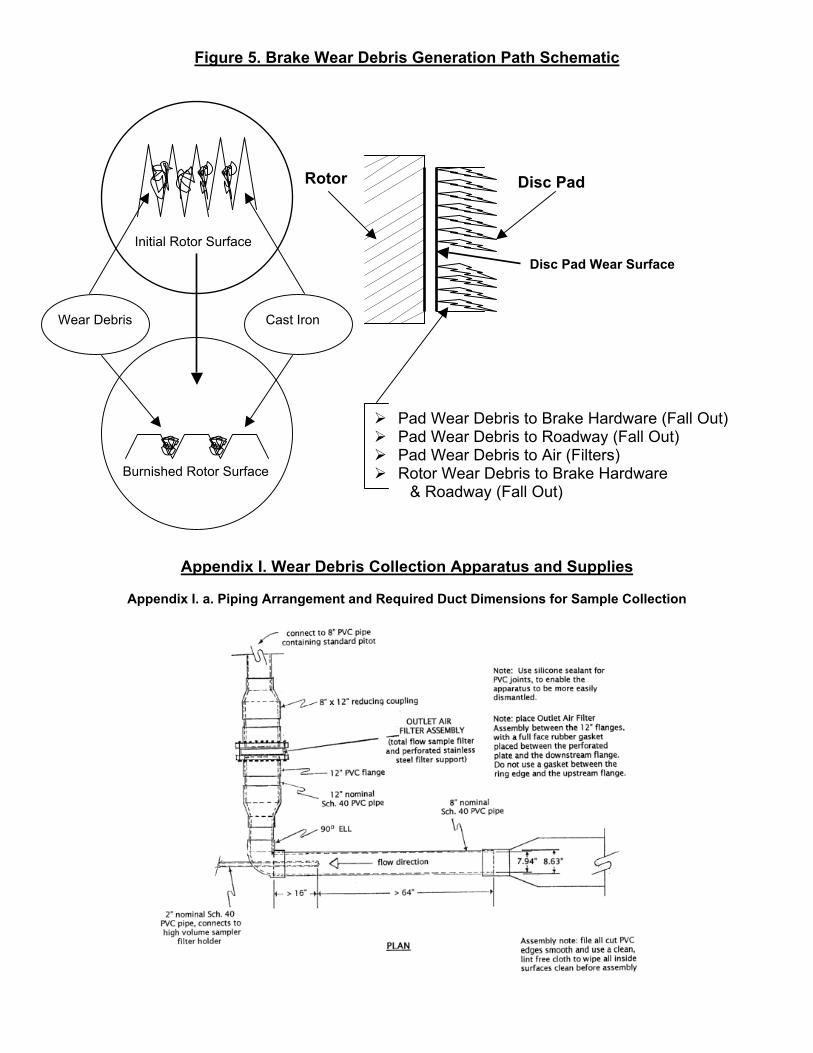
Figure 5. Brake Wear Debris Generation Path Schematic
Appendix I. Wear Debris Collection Apparatus and Supplies
Appendix I. a. Piping Arrangement and Required Duct Dimensions for Sample Collection
Initial Rotor Surface
Burnished Rotor Surface
Wear Debris Cast Iron
Rotor Disc Pad
Disc Pad Wear Surface
Pad Wear Debris to Brake Hardware (Fall Out) Pad Wear Debris to Roadway (Fall Out) Pad Wear Debris to Air (Filters) Rotor Wear Debris to Brake Hardware
& Roadway (Fall Out)
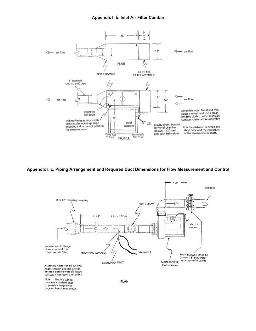
Appendix I. b. Inlet Air Filter Camber
Appendix I. c. Piping Arrangement and Required Duct Dimensions for Flow Measurement and Control
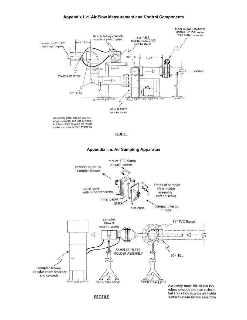
Appendix I. d. Air Flow Measurement and Control Components
Appendix I. e. Air Sampling Apparatus
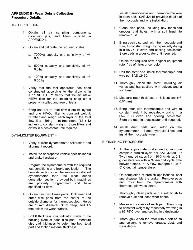
APPENDIX II - Wear Debris Collection Procedure Details
TEST PROCEDURE:
1. Obtain all air sampling components, collection jars, and filters outlined in APPENDIX I.
2. Obtain and calibrate the required scales.
a. 7000+g capacity and sensitivity of +/- 0.1g
b. 500+g capacity and sensitivity of +/- 0.01g
c. 100+g capacity and sensitivity of +/- 0.001g
3. Verify that the test apparatus has been constructed according to the drawing in APPENDIX I. ** Verify that the air intake HEPA filter for the incoming shop air is properly installed and free of leaks.
4. Bring one set of total flow filters (6 layers) and one HIVOL filter to constant weight. Number and weigh each layer of the total flow filter. Bring 4 lint free cloths (12 x 12 inches) to constant weight. Store filters and cloths in a desiccator until required.
DYNAMOMTER EQUIPMENT –
1. Verify current dynamometer calibration and alignment record.
2. Install the appropriate vehicle specific inertia and brake hardware.
3. Program the dynamometer with the required test conditions and brake application. The burnish sections can be run on a different dynamometer than the wear debris generation section, provided both machines are properly programmed and have specified air flow.
4. Obtain new disc brake parts. Drill inner and outer disc pads from the center of the outside diameter for thermocouples. Holes are 1.5mm diameter, 3mm deep, and 1.5 mm below the wear surface.
5. Drill 6 thickness loss indicator marks in the backing plate of each disc pad. Measure disc pad thickness to determine both total part and friction material thickness.
6. Install thermocouple and thermocouple wire in each pad. SAE J2115 provides details of thermocouple and wire installation.
7. Clean disc pads, including any machined grooves and holes, with a soft brush to remove dust.
8. Bring each disc pad, with thermocouple and wire, to constant weight by repeatedly drying in a 65-75° F oven and cooling desiccator. Store pads in a desiccator until required.
9. Obtain the required new, original equipment rotor free of nicks or corrosion.
10. Drill the rotor and install thermocouple and wire per SAE J2430.
11. Thoroughly clean the rotor, including air vanes and hat section, with solvent and a soft brush.
12. Measure rotor thickness at 8 locations (+/- 0.01mm).
13. Bring rotor with thermocouple and wire to constant weight by repeatedly drying in a 65-75° C oven and cooling desiccator. Store the rotor in a desiccator until required.
14. Install disc pads and rotor on the dynamometer. Bleed hydraulic lines and install thermocouple wires.
BURNISHING PROCEDURE –
1. At the appropriate brake inertia, run one complete burnish cycle per SAE J2430. ** Two hundred stops from 80-3 km/hr at 0.31 g deceleration with a 97-second cycle time between stops. ** Airflow 1500fpm at 25+/-5° C duct air temperature.
2. On completion of burnish applications, cool and disassemble the brake. Remove pads and rotor from the dynamometer with thermocouple wires intact.
3. Thoroughly clean pads with a soft brush to remove dust and loose wear debris.
4. Measure thickness of each pad. Then bring to constant weight by repeatedly warming in a 65-75°C oven and cooling in a desiccator.
5. Thoroughly clean the rotor with a soft brush and solvent to remove grease, dust, and wear debris.
6. Measure rotor thickness at eight locations. ** Rotor thickness may increase from the pretest values due to material transfer during the burnish.
7. Bring the rotor with thermocouple wire to constant weight by repeatedly warming in a 65-75° C oven and cooling in a desiccator. Store in a desiccator.
COLLECTION APPARATUS AND INSTRUMENTATION SETUP –
1. Calibrate the HIVOL sampler airflow according to the manufacturer’s specifications.
2. Thoroughly clean the brake hardware with a wire brush and solvent to remove grease and dust.
3. Clean the test chamber, piping and sampler pipe assembly as follows:
a. Move the brake test assembly inside the chamber, tilt the chamber onto ½” blocks, and use a squirt bottle with DIUF water to wash down the assembly. Allow water to flow through the gravity drain and accumulate in a large pan below the chamber.
b. Move the brake test assembly out of the test chamber to wash down the walls, ceiling, and doors of the chamber with DIUF water.
c. Remove the sampler piping and attached inlet cone. Rinse the inside surfaces of this assembly with DIUF water and wipe dry with a lint free cloth. Reinstall sampler pipe assembly.
4. Install disc pads and rotor. Bleed the hydraulic lines.
5. Wrap the knuckle with a thin plastic sheet and dust tape to minimize wear debris collection in difficult to clean areas of the brake hardware.
6. Move the brake assembly into the test chamber, close doors, and use duct tape to seal the enclosure. Close the valve on the chamber’s gravity drain.
7. Without installing the total flow or HIVOL filters, but with the HEPA filter and the entire apparatus in place, turn the main blower and allow the system to run for 2 hours to remove remaining moisture and dust inside the piping. Shut down main blower.
8. Install a full face rubber gasket on the down stream face of the 12” total flow filter flange, remove all but the bottom 4 bolts. Install the pre-weighed set (6 layers) of the total flow filters in the filter holder, and then position the filter holder between the two 12” flanges resting on the bottom bolts. Insert remaining bolt and tighten the flange to secure the filter holder.
9. Completely close the main blower damper. Install the pre-weighed filter in the HIVOL sampler. Switch on the sampler blower and adjust the airflow so that it reads greater then 40 cfm on the circular chart recorder.
10. With the main blower damper closed, and the sampler blower running, switch on the main blower and immediately open the main damper slightly. CAUTION: Do not switch on the main blower with the sampler blower off and the damper open, the filter paper could be vacuumed back into the sampling pipe.
11. Position the Pitot tube at the center of the main air dust. Open the main blower valve slowly while watching the magnehelic gauge, until the desired 1500 fpm is achieved on the gauge.
12. Follow the manufacturer’s recommendations for positioning the Pitot tube and tighten the mounting adapter to secure the Pitot.
13. Once the Pitot is set, adjust the main blower damper to maintain 1500 fpm at the magnehelic gauge.
14. Adjust the position of the sampler blower stand so that the center of the sampler pipe is in the exact center of the 8” main pipe, and the 2” sampler pipe is in the correct horizontal position. With duct tape, seal any space around the sampler pipe where it exits the 8” pipe.
15. Calibrate the HIVOL sampler flow per manufacturer’s specifications. Set the sampler to a constant flow rate of 37 cfm, which corresponds to 1500 fpm air velocity in the 2” sampler pipe. The objective is to match the main pipe air velocity.
16. Leak test the entire chamber, HEPA filter, flanges, and fittings with a smoke source. Correct any leaks as required.
WEAR DEBRIS GENERATION BRAKE CYCLES –
1. Verify correct brake inertia, test conditions and brake application sequence.
2. Turn on the dynamometer and begin the brake application sequence. Verify that the sampler is set at 37 cfm and the magnehelic gauge remains constant at 1500 fpm.
3. If the sampler blower is no longer able to maintain 37 cfm during the test, this indicates that the sampler filter paper is clogged. Discontinue the test.
4. On completion of the specific wear debris generation period (18 Hours, about 8.5 cycles), shut down the dynamometer, close the main blower damper, and immediately shut down the main blower. ** CAUTION: Do not shut down the sampler blower until the main blower damper is closed and the main blower is shut off.
5. Wait one minute and shut down the sampler blower.
6. Allow the brake hardware to cool.
DISASSEMBLY AND SAMPLE COLLECTION–
1. Remove the 8” x 10” filter from the HIVOL sampler. Photograph the paper. Bring the filter paper to constant weight by conditioning in a desiccator.
2. Remove the 2” sample pipe assembly and gasket and set aside for later washing with DIUF Water.
3. Loosen the bolts on the 12” flange in the main pipe. Remove all bolts except the bottom 4. Remove the filter holder assembly and carefully pry out the 6 ply pleated total flow filter. Note and record its condition, photograph the paper. Bring each layer to constant weight by conditioning in a desiccator. ** CAUTION: Do not heat total flow filter to greater then 65° C. Polypropylene fibers can soften.
4. Remove tape from the test chamber. Open doors and retract brake assembly from the chamber.
5. Using a pre-weighed 57-gram soil jar, collect a 100 to 150 mg sample of dry particulate from the wheel rim. Bring to constant weight by conditioning in a desiccator.
6. Tilt the chamber as before. Place the small funnel in a pre-weighed 1-liter glass jar and place this assembly beneath the chamber drain valve. Carefully wash debris with DIUF water from the plastic sheet around the brake hardware.
7. Carefully wash wear debris with DIUF water from the wheel rim, test chamber and test parts. Allow water to gravity feed into pre-weighed, 1-liter glass jars positioned under the gravity drain. ** With rubber gloves, rubbing surfaces with a finger can assist in loosening wear debris or water removal.
8. Remove the tested disc brake parts and rotor from the brake assembly. Carefully wash with DIUF water into the gravity feed drain. Bring the disc pads and rotor to constant weight in a desiccator. Photograph the tested disc pads and rotor.
9. Place a large funnel into a pre-weighed 1-liter glass jar and add about the same amount of DIUF water as added to the other jars. This becomes the field blank sample.
10. Cut the silicone seal around the first joint in the 90-degree ell and remove the ell. With latex gloves and a pre-weighed lint free cloth, wipe the inside surface of the ell and pipe interior. Dry cloths to constant weight in a desiccator.
11. After the rotor is weighed and photographed, measure the thickness at 8 locations.
12. After the pads are weighed and photographed, measure thickness at 6 locations on each pad.