Embed Size (px)
Citation preview
1

2
DISCLAIMER HOIST PROWINCH®
Prowinch® LLC declares that it has made available to the Customer each and every one of the security warnings related to the purchased product and that, as a result, it does not assume any
responsibility for any damages or losses that may be suffered by the client or third parties. cause or as a direct or indirect consequence of the breach or omission of any of the instructions or
safety warnings contained in the User Manual and Security Warnings corresponding to the unit purchased.
In this sense, Prowinch® LLC will not be liable for accidents and / or damages to persons and / or property resulting from the negligent use of the product.
In no case does Prowinch® LLC assume any liability arising from the use of these voluntary recommendations, and does not offer any guarantee in relation to them. These recommendations
do not take precedence over the current safety regulations of the plant.
For purposes of enforcing the Warranty of the product purchased, Prowinch® LLC, will only be liable for any damage when it is possible to prove that the user has followed each and every one
of the warnings contained in the User Manual and Safety Warnings.
1. It is the sole responsibility of the Client / User to verify that the acquired equipment, products and accessories comply with the characteristics, capacities, elements, components, accessories
and other conditions for the use that the Client / user intends to give it.
2. It is also the sole responsibility of the Client / User to ensure that the equipment and products purchased are operated and maintained in safety conditions and by personnel duly trained
in the use thereof, also implementing all the security measures necessary for prevent accidents or damages to people or property and observing the indications and warnings of the corre-
sponding manuals of use.
3. The possible support in the selection of the equipment, the capacities and characteristics required by the clients that Prowinch provides is delivered free of charge and provided based on
the information of use and requirements indicated by the Client itself, information that Prowinch does not It may not correspond to verify. In this way, it is in any case the sole and exclusive
responsibility of the Client -or who will use the equipment and products acquired- to ensure that they comply with the capabilities, characteristics, up-to-date maintenance and everything
necessary for a correct and safe operation in relation to the intended use.
4. For personnel lifting Prowinch recommends the use of winches with 4 brakes. The use of winches of 3 or less brakes or safety features lower than the maximum available, for personnel
lifting, is the sole responsibility of the customer.
5. In order to guarantee the safety of the users of the equipment, especially those of Personnel, it is necessary to carry out the inspections and maintenance of the equipment according to
the recommended frequency in relation to its work cycle, as it is described by the ASME B30 standards. It is mandatory to keep record and evidence the written and photographic reports of:
Maintenance, Start-up, Load Tests, Training, Certifications, Inspections and Reports of failures and accidents.
6. The aforementioned reports must be sent by email to [email protected] within the first 7 calendar days that said event has occurred.
7. Compliance with the timely implementation of the mandatory activities described in points 6 and 7, plus all the activities mentioned in the corresponding rules applied, are the sole
responsibility of the user. Failure to comply with the foregoing, releases Prowinch from any type of Liability and Warranty to the team, customer, staff and / or user or any other liability that
could be attributed to Prowinch.
The information contained in this manual may contain technical errors or inaccuracies, Prowinch® LLC, is not responsible for errors typing, omission or incorrect information.
This manual is subject to change without prior notice. Download the latest version available at www.prowinch.com
Always check www.prowinch.com for latest information regarding this product.
INTELECTUAL PROPERTY REGISTRY Nº 189487ANY REPRODUCTION IS FORBIDDENALL RIGHTS RESERVED ARE PROPERTY OF THE AUTHOR ® PROWINCH 2017 - V7.0PROWINCH LLC COMPANY WITH QUALITY MANAGEMENT SYSTEM
3
Index
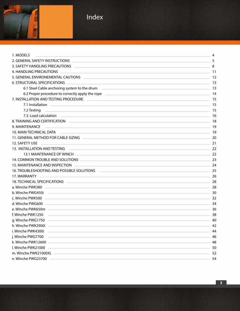
1. MODELS 42. GENERAL SAFETY INSTRUCTIONS 53. SAFETY HANDLING PRECAUTIONS 84. HANDLING PRECAUTIONS 115. GENERAL ENVIRONEMENTAL CAUTIONS 126. STRUCTURAL SPECIFICATIONS 13 6.1 Steel Cable anchoring system to the drum 13 6.2 Proper procedure to correctly apply the rope 147. INSTALLATION AND TESTING PROCEDURE 15 7.1 Installation 15 7.2 Testing 15 7.3. Load calculation 168. TRAINING AND CERTIFICATION 189. MAINTENANCE 1910. MAIN TECHNICAL DATA 1911. GENERAL METHOD FOR CABLE SIZING 2012. SAFETY USE 2113. INSTALLATION AND TESTING 22 13.1 MAINTENANCE OF WINCH 2214. COMMON TROUBLE AND SOLUTIONS 2315. MAINTENANCE AND INSPECTION 2416. TROUBLESHOOTING AND POSSIBLE SOLUTIONS 2517. WARRANTY 26 18. TECHNICAL SPECIFICATIONS 28a. Winche PWK380 28b. Winche PWG450i 30c. Winche PWK500 32d. Winche PWG600 34e. Winche PWK650m 36f. Winche PWK1250 38g. Winche PWG1750 40h. Winche PWK2900i 42i. Winche PWK4300i 44j. Winche PWG7700 46k. Winche PWK12600 48l. Winche PWK21000 50m. Winche PWK21000XL 52n. Winche PWG23700 54
4
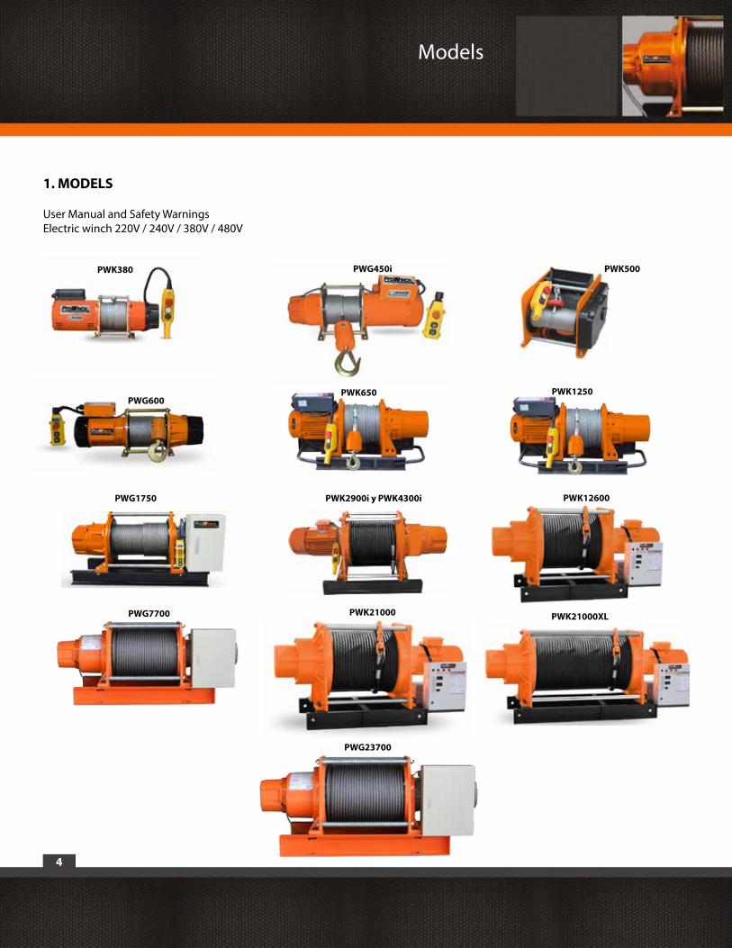
User Manual and Safety WarningsElectric winch 220V / 240V / 380V / 480V
PWG600PWK650 PWK1250
PWG1750 PWK2900i y PWK4300i
PWK380
PWG7700
PWK12600
PWG23700
Models
PWK500
PWK21000 PWK21000XL
PWG450i
1. MODELS
5
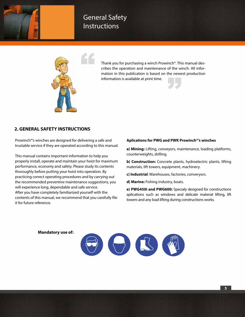
Thank you for purchasing a winch Prowinch®. This manual des-cribes the operation and maintenance of the winch. All infor-mation in this publication is based on the newest production information is available at print time.
“ “
General Safety Instructions
Prowinch®’s winches are designed for delivering a safe and trustable service if they are operated according to this manual.
This manual contains important information to help you properly install, operate and maintain your hoist for maximum performance, economy and safety. Please study its contents thoroughly before putting your hoist into operation. By practicing correct operating procedures and by carrying out the recommended preventive maintenance suggestions, you will experience long, dependable and safe service.After you have completely familiarized yourself with the contents of this manual, we recommend that you carefully file it for future reference.
Aplications for PWG and PWK Prowinch®’s winches
a) Mining: Lifting, conveyors, maintenance, loading platforms, counterweights, drilling.
b) Construction: Concrete plants, hydroelectric plants, lifting materials, lift towers, equipment, machinery.
c) Industrial: Warehouses, factories, converyors.
d) Marine: Fishing industry, boats.
e) PWG450i and PWG600: Specialy designed for constructions aplications such as windows and delicate material lifting, lift towers and any load lifting during constructions works.
2. GENERAL SAFETY INSTRUCTIONS
Mandatory use of:
6
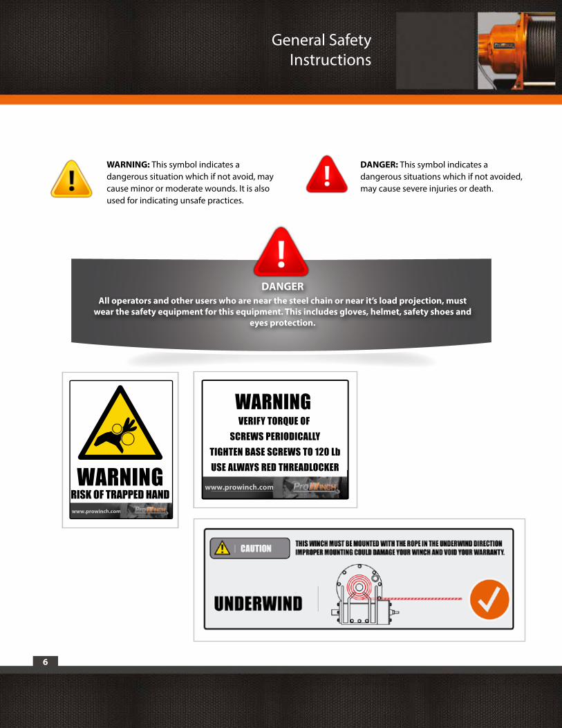
WARNING: This symbol indicates a dangerous situation which if not avoid, may cause minor or moderate wounds. It is also used for indicating unsafe practices.
DANGER: This symbol indicates a dangerous situations which if not avoided,may cause severe injuries or death.
DANGERAll operators and other users who are near the steel chain or near it’s load projection, must
wear the safety equipment for this equipment. This includes gloves, helmet, safety shoes and eyes protection.
General Safety Instructions
WARNINGRISK OF TRAPPED HANDRISK OF TRAPPED HANDwww.prowincchh.ccoommmm
www.prowincchhh.ccoooommmmm
WARNING VERIFY TORQUE OF
SCREWS PERIODICALLYTIGHTEN BASE SCREWS TO 120 LbUSE ALWAYS RED THREADLOCKER
7
2.1. Handling Precautions:- Keep the winch in best conditions. Failure to adequately align, support, or attach winch to a suitable mounting base could result in a loss of efficiency or premature failure of winch, wire rope, or mounting base.- Do not use any chain or cable that was not designed for the unit you are using.- To avoid an electrical discharge, make sure that your equipment is adequately grounded, by certified personnel.- Make sure the winch works properly without load , before applying loads.- Do not lift weight with the edge of the hook.- Do not perform lifting with more than one winch at once.- Never exceed the maximum weight lifting capacity.- Disconnect the equipment from the power supply in order to avoid any involuntary use.- Do not use pulleys or accessories that are not approved for this winch.
2.2. Wear appropriate protective clothing:- Do not use loose clothing or any jewellery when operating this equipment.- You must wear protective leather gloves when handling the winch rope.- You must wear non-slippery safety footware,safety helmet.- Long hair must be tied back to operate this equipment.- You must wear appropiate safety glasses to operate this equipment.
2.3. Keep a safe distance:- Always stand clear, keep hands clear, keep others away at least 1.5 times the lenght of the wich rope. Wire rope can break without warning. - Never touch the rope or hook while they are in tension or under load. Even at rest, the winch may have the rope in tension. Never guide a rope under tension onto the drum with your hands.
2.4. Power cord misuse:- Do not lift the winch or any equipment from the power cord.- Never route electrical cables across sharp edges.- Never route electrical cables near parts that get hot.- Never route electrical cables through or near moving parts.- Never route electrical cables over battery terminals.- Always insulate and protect all exposed wiring and electrical terminals.
2.5. Do not overwork the equipment:- If the motor overheads, stop any operations let the winch cold, check for any damage before restart operation.- If the winch stops during it’s operation, stop and check for any damage before restart operation.- Do not exceed maximum rated capacity.
2.6. Check for damaged parts:- Before using this equipment, check for any visual damage in the motor or wire rope.
2.7. Winch repair:- In order to repair a Prowinch® winch, use only original Prowinch® parts. Using unauthorized parts will void warranty.
2.8. Winding the winch cable:- You must wear leather gloves to handling the winch rope. To proceed properly you need to apply and maintain a small load on the rope. While the operator winds the rope someone else should lead to correct location. Start as far as possible keeping it centered.- Do not let the winch rope falls off and always keep a safe distance from the winch.- Repeat this process until one (1) meter of cable was been left unwind.- Disconnect the remote or/and from the power source.- The last five wraps of wire rope must be left on the drum to assist the wire rope clamp in holding the load.
General Safety Instructions
8
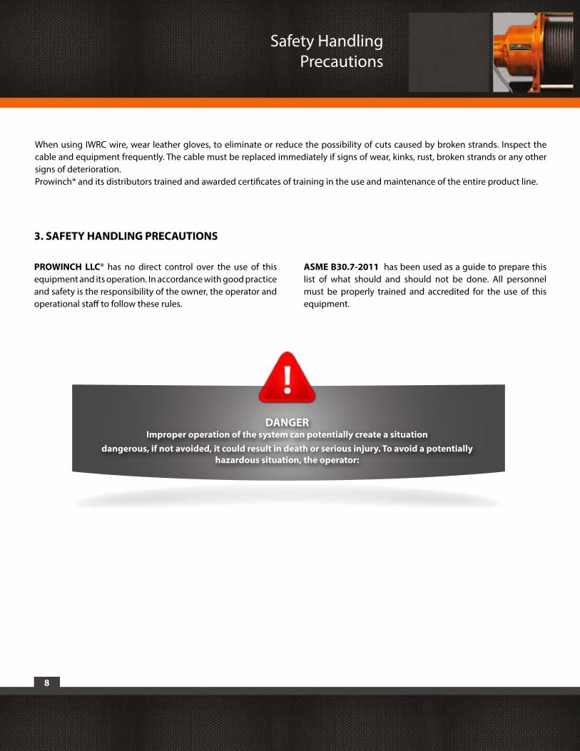
DANGER Improper operation of the system can potentially create a situation
dangerous, if not avoided, it could result in death or serious injury. To avoid a potentially hazardous situation, the operator:
Safety Handling Precautions
PROWINCH LLC® has no direct control over the use of this equipment and its operation. In accordance with good practice and safety is the responsibility of the owner, the operator and operational staff to follow these rules.
ASME B30.7-2011 has been used as a guide to prepare this list of what should and should not be done. All personnel must be properly trained and accredited for the use of this equipment.
3. SAFETY HANDLING PRECAUTIONS
When using IWRC wire, wear leather gloves, to eliminate or reduce the possibility of cuts caused by broken strands. Inspect the cable and equipment frequently. The cable must be replaced immediately if signs of wear, kinks, rust, broken strands or any other signs of deterioration.Prowinch® and its distributors trained and awarded certificates of training in the use and maintenance of the entire product line.

9
3.1. Do not operate the winch until you have read and understood all these rules and the equipment manual delivered by PROWINCH LLC® , including instructions and maintenance manuals.
3.2. Do not operate a damaged equipment, that functions incorrectly.
3.3. Do not operate a equipment that has been modified without previous PROWINCH® approval.
3.4. Do not exceed the max. rated load.
3.5. Do not use this equipment with cable damage: twists, bends, rust, broken strands or worn.
3.6. Do not use any extensions or modifications to the equipment.
3.7. Do not release the load when the equipment is loaded.
3.8. Do not use this equipment to lift people except for those equipments that meet the standard ASME B30.7- 2011 in facilities that comply with the ASME B30.23-2005 or are approved by SERNAGEOMIN.
3.9. Do not lift loads over people and make sure that all personnel remains distant from the supported load.
3.10. Do not try to extend or repair the cable.
3.11. Protect the loading cable from welding spatters or other harmful contaminants.
3.12. Do not operate the winch if there is any object or friction element or improperly deviating the cable.
3.13. Do not apply the load to the tip of the hook or to the hook latch.
3.14. Do not use equipment with an accessory, pulley, sling, shackle or any additional element that is not in proper condition and meets the specifications required for loading the maneuver.
3.15. Do not operate beyond the limits of travel.
3.16. Do not leave any load being lifted by the equipment without specific precautions are taken.
3.17. Do not use the load cable as a ground for welding.
3.18. Do not allow the cable or hook to be touched by a welding electrode.
3.19. Do not loose or hide this Safety Handling Precautions.
3.20. Do not operate an equipment that has not been installed and anchored meeting the calculations and regulations.
3.21. Do not lift loads that are not in balance.
3.22. Do not lift loads that are not balanced and that the holding action is not secure, always keeping the corrisponding slack.
3.23. Report any malfunction or irregular operation of the equipment.
3.24. Do not operate any equipment on which the safety placards or decals are missing or illegible.
3.25. Do not operate the equipment without safety wear: safety footwear, protective gloves, safety helmet, safety glasses and any additional required element.
3.26. Unplug the power cord if the equipment will not be used.
3.27. Electrical connection must have a circuit breaker that allows de-energize the equipment. This should be within reach of the operator.
3.28. Do not operate the equipment without engine and moving parts protection.
Safety Handling Precautions
10
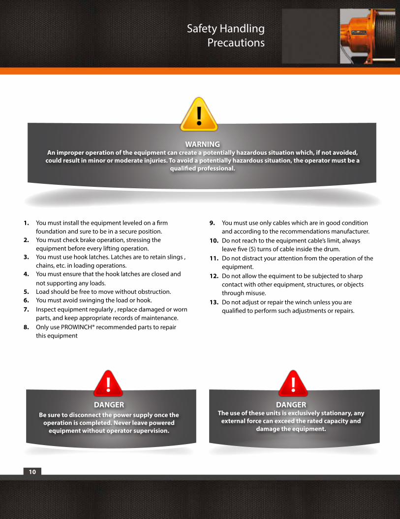
1. You must install the equipment leveled on a firm foundation and sure to be in a secure position.2. You must check brake operation, stressing the equipment before every lifting operation.3. You must use hook latches. Latches are to retain slings , chains, etc. in loading operations.4. You must ensure that the hook latches are closed and not supporting any loads.5. Load should be free to move without obstruction.6. You must avoid swinging the load or hook.7. Inspect equipment regularly , replace damaged or worn parts, and keep appropriate records of maintenance.8. Only use PROWINCH® recommended parts to repair this equipment
9. You must use only cables which are in good condition and according to the recommendations manufacturer.10. Do not reach to the equipment cable’s limit, always leave five (5) turns of cable inside the drum.11. Do not distract your attention from the operation of the equipment.12. Do not allow the equiment to be subjected to sharp contact with other equipment, structures, or objects through misuse.13. Do not adjust or repair the winch unless you are qualified to perform such adjustments or repairs.
WARNING An improper operation of the equipment can create a potentially hazardous situation which, if not avoided,
could result in minor or moderate injuries. To avoid a potentially hazardous situation, the operator must be a qualified professional.
DANGERBe sure to disconnect the power supply once the
operation is completed. Never leave powered equipment without operator supervision.
Safety Handling Precautions
DANGER The use of these units is exclusively stationary, any
external force can exceed the rated capacity and damage the equipment.
11
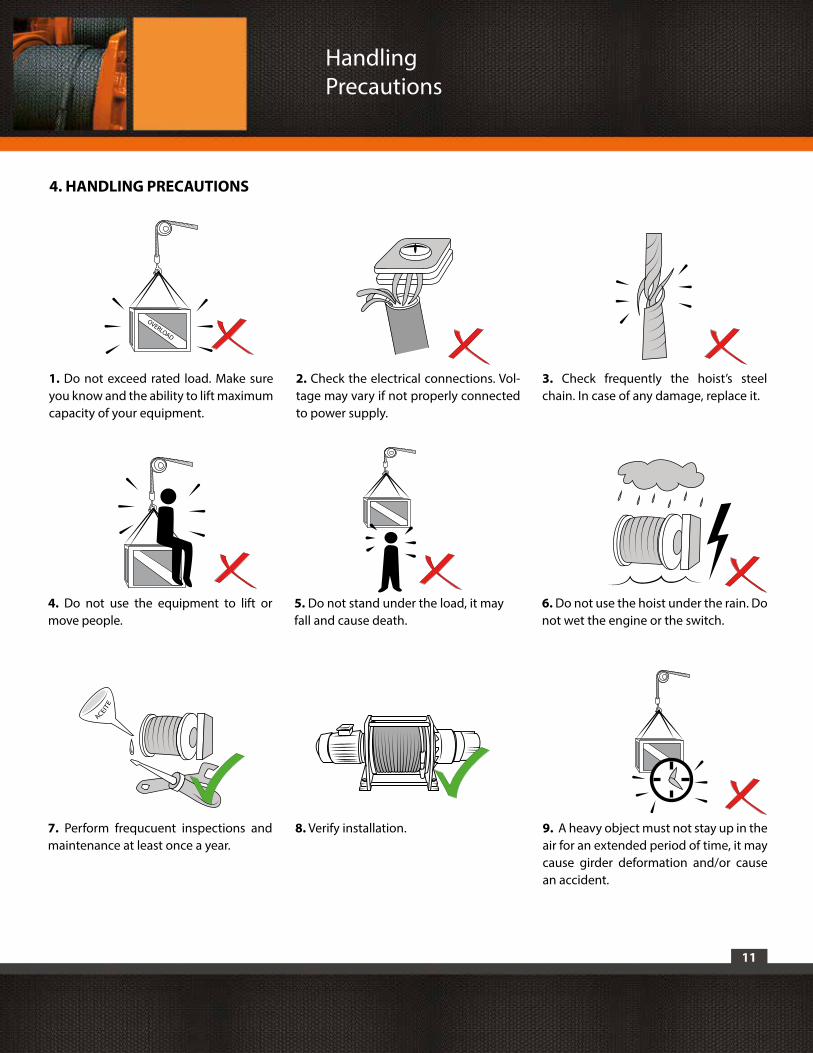
5. Do not stand under the load, it may fall and cause death.
Handling Precautions
4. HANDLING PRECAUTIONS
1. Do not exceed rated load. Make sure you know and the ability to lift maximum capacity of your equipment.
4. Do not use the equipment to lift or move people.
7. Perform frequcuent inspections and maintenance at least once a year.
8. Verify installation.
6. Do not use the hoist under the rain. Do not wet the engine or the switch.
2. Check the electrical connections. Vol-tage may vary if not properly connected to power supply.
3. Check frequently the hoist’s steel chain. In case of any damage, replace it.
OVERLOAD
9. A heavy object must not stay up in the air for an extended period of time, it may cause girder deformation and/or cause an accident.
12
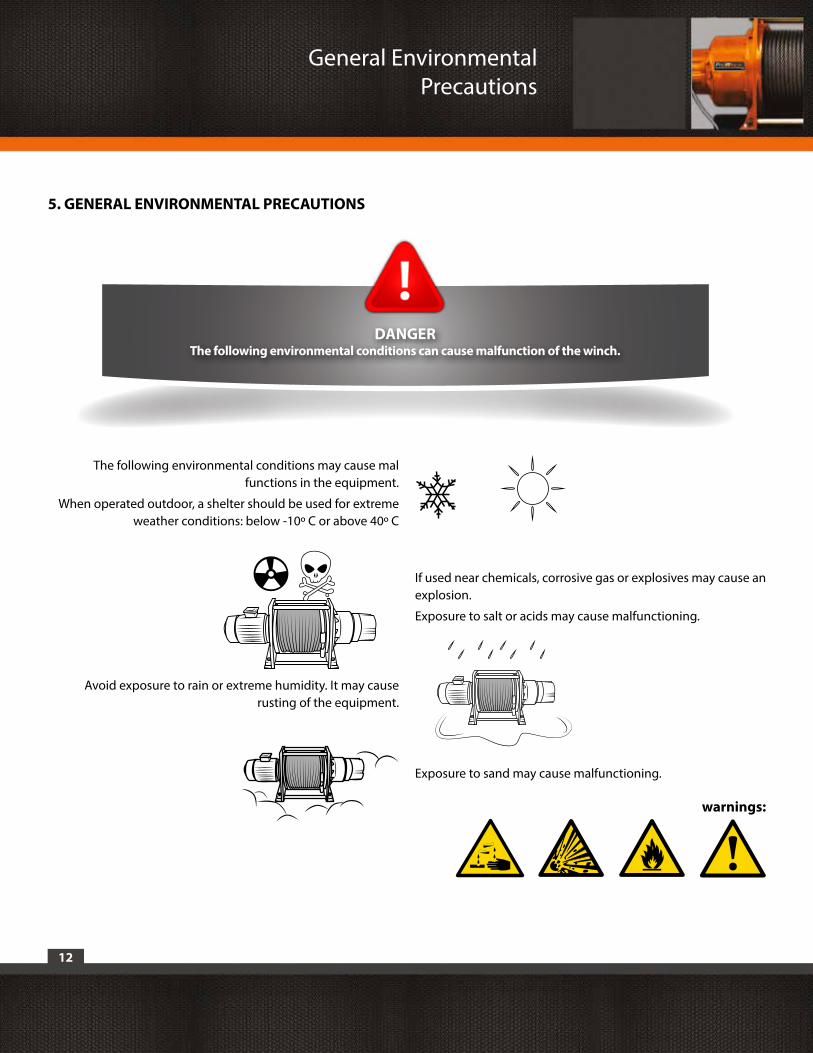
Avoid exposure to rain or extreme humidity. It may cause rusting of the equipment.
The following environmental conditions may cause mal functions in the equipment.
When operated outdoor, a shelter should be used for extreme weather conditions: below -10º C or above 40º C
If used near chemicals, corrosive gas or explosives may cause an explosion.
Exposure to salt or acids may cause malfunctioning.
Exposure to sand may cause malfunctioning.
warnings:
General Environmental Precautions
DANGER The following environmental conditions can cause malfunction of the winch.
5. GENERAL ENVIRONMENTAL PRECAUTIONS
13
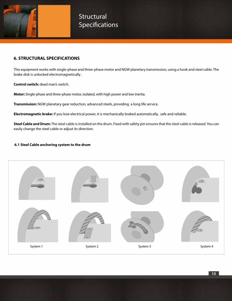
6. STRUCTURAL SPECIFICATIONS
This equipment works with single-phase and three-phase motor and NGW planetary transmission, using a hook and steel cable. The brake disk is unlocked electromagnetically .
Control switch: dead man’s switch.
Motor: Single-phase and three-phase motor, isolated, with high power and low inertia.
Transmission: NGW planetary gear reduction, advanced steels, providing a long life service.
Electromagnetic brake: If you lose electrical power, it is mechanically braked automatically, safe and reliable.
Steel Cable and Drum: The steel cable is installed on the drum. Fixed with safety pin ensures that the steel cable is released. You can easily change the steel cable or adjust its direction.
Structural Specifications
6.1 Steel Cable anchoring system to the drum
System 1 System 2 System 3 System 4
14
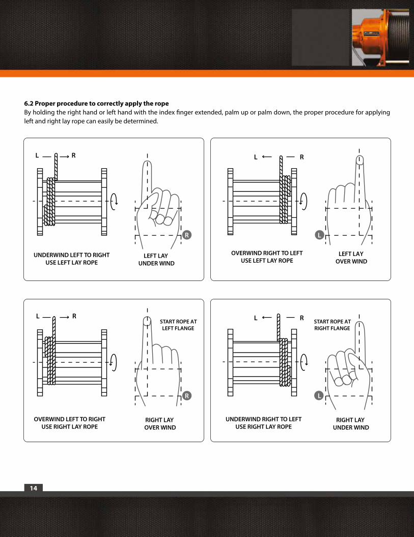
LEFT LAY UNDER WIND
R
R
LEFT LAY OVER WIND
L
L
UNDERWIND LEFT TO RIGHTUSE LEFT LAY ROPE
R
RIGHT LAY OVER WIND
RL
L
START ROPE ATLEFT FLANGE
OVERWIND LEFT TO RIGHTUSE RIGHT LAY ROPE
OVERWIND RIGHT TO LEFTUSE LEFT LAY ROPE
START ROPE ATRIGHT FLANGE
RIGHT LAY UNDER WIND
UNDERWIND RIGHT TO LEFTUSE RIGHT LAY ROPE
6.2 Proper procedure to correctly apply the ropeBy holding the right hand or left hand with the index finger extended, palm up or palm down, the proper procedure for applying left and right lay rope can easily be determined.
RL
RL
15
7.1 Installation- The supporting structure the winch is mounted to, must be designed by an engineer, to withstand the loads and forces by the winch for the rated load.- Install in location that allows the operator to move and stay clear of the load.- Locate pendant controls at a convenient level above the operating floor.- Do not install where the load hook can be lowered beyond rated hook travel under normal operating conditions.- Check that power supply meets the requirements of the equipment to be installed. If the power supply does not meet the requirements stipulated in the nameplate of the equipment can cause damage to electrical parts and winch motor. The voltage should be +/-5% fo the specified value.- If the circuit of the electrical connection is correct, the operating direction of the winch should be as the control switch. Otherwise check that the phases are not reversed.
7. INSTALLATION AND TESTING PROCEDURE
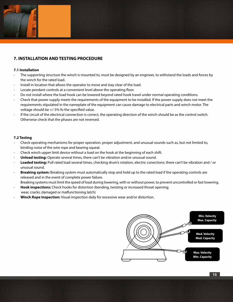
7.2 Testing- Check operating mechanisms for proper operation, proper adjustment, and unusual sounds such as, but not limited to, binding noise of the wire rope and bearing squeal.- Check winch upper limit device without a load on the hook at the beginning of each shift.- Unload testing: Operate several times, there can’t be vibration and/or unusual sound. - Loaded testing: Pull rated load several times, checking drum’s rotation, electric conections; there can’t be vibration and / or unusual sound. - Breaking system: Breaking system must automatically stop and hold up to the rated load if the operating controls are released and in the event of complete power failure. Breaking systems must limit the speed of load during lowering, with or without power, to prevent uncontrolled or fast lowering.- Hook inspections: Check hooks for distortion (bending, twisting or increased throat opening; wear, cracks; damaged or malfunctioning latch)- Winch Rope Inspection: Visual inspection daily for excessive wear and/or distortion.
Max. VelocityMin. Capacity
Med. VelocityMed. Capacity
Min. VelocityMax. Capacity
16
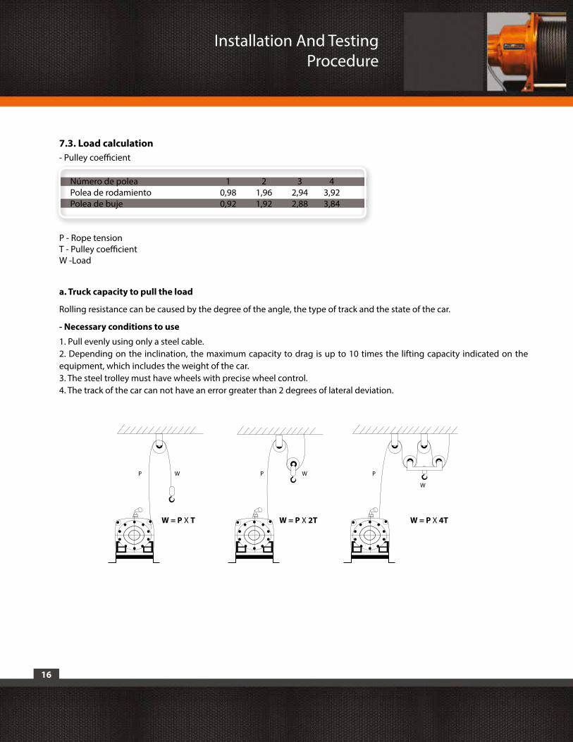
7.3. Load calculation- Pulley coefficient
Número de poleaPolea de rodamiento Polea de buje
43,923,84
21,961,92
10,980,92
32,942,88
P - Rope tensionT - Pulley coefficientW -Load
W = P X T
P P PW W
W
W = P X 2T W = P X 4T
Installation And Testing Procedure
a. Truck capacity to pull the load
Rolling resistance can be caused by the degree of the angle, the type of track and the state of the car.
- Necessary conditions to use
1. Pull evenly using only a steel cable.2. Depending on the inclination, the maximum capacity to drag is up to 10 times the lifting capacity indicated on the equipment, which includes the weight of the car.3. The steel trolley must have wheels with precise wheel control. 4. The track of the car can not have an error greater than 2 degrees of lateral deviation.
17
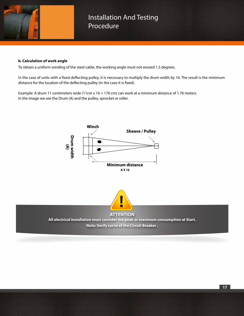
A X 16
Sheave / PulleyWinch
Minimum distance
Drum
width
(A)
ATTENTIONAll electrical installation must consider the peak or maximum consumption at Start.
Note: Verify curve of the Circuit Breaker .
Installation And Testing Procedure
b. Calculation of work angle
To obtain a uniform winding of the steel cable, the working angle must not exceed 1.5 degrees.
In the case of units with a fixed deflecting pulley, it is necessary to multiply the drum width by 16. The result is the minimum distance for the location of the deflecting pulley (in the case it is fixed).
Example: A drum 11 centimeters wide (11cm x 16 = 176 cm) can work at a minimum distance of 1.76 meters.In the image we see the Drum (A) and the pulley, sprocket or roller.
18
WARNINGThe owner assumes responsability to install the unit by qualified professional. All structural calculations must be done by a Certified Structural Engineer. An improper installation will lead to accidents that could harm or
cause death to users or people near work site. An improper installation and incorrect electrical connection will terminate the warranty. Any intervention to this unit without Prowinch®’s aproval will terminate the warranty.
In order to contribute to the protection and safety of all users, workers , employees, employers, owners and all those involved in the operation and use of winches, Prowinch® provides training for use and maintenance of winches applied to different types of work .
On the understanding that safety has not only to do with a particular equipment, but also with the whole chain of processes involved in the installation, operation, maintenance and use of such equipment.
For this purpose we have developed manuals applied to the installation, usage and maintenance of winches and lifting of personnel platforms , which contain important references and indications that are necessary to know, consider or check for safe and proper use of winches, that together with its parts and accessories can meet safely the expected life cycle and work.
This manuals have been developed considering our experience and based on the main indications emanating from ASME B30.7 and ASME B30.23 Personnel Lifting Systems.
Prowinch® has acquired the rights and received the necessary authorizations and licenses by the American Society of Mechanical Engineers ASME to translate and reproduce these standards, with the written consent of the ASME, in order to apply them in our instruction manuals in a number of controlled and copyright corresponding copies.
We invited you to come and meet us and we will give our advice.
8. TRAINING AND CERTIFICATION
Training and Certification

19
Maintenance
9. MAINTENANCE
The equipment has a planetary gear for maximum mechanical efficiency. Verify your equipment is well lubricated. Apply grease in the grease fitting every three months (only for models with that fitting).
Keep lubricated steel cable, if it is oxidized or is corroded by rain water or weather, please remove the entire cable and apply the recommended lubricant . If corrosion has affected the cable, replace it.The electric winch must be inspected and frequently used. It should be fully inspected every six months.
ATTENTIONIt is your responsibility to periodically check the condition of the steel cable, anchor or any parts
that can be worn loose or damaged in both the unit and the object to move.
10. MAIN TECHNICAL DATA
Model KDJ-2200E1 KDJ-3200E1 KDJ-3500E1
Rated load 2200 3200 3500
Speed (m/min) 7-12.5 7-12.5 7-12.5
Lift (m) 97 97 140
Rated power(kW) 6 7.5 9
Voltage (v) Three phase 380VAC
Frequency (Hz) 50Hz
Electric current (A) 12 15.4 18.2
Diameter of the 16 18 18 cable wire (mm)
Capacity of cable (m) 100 100 143
N.W. (kg) 473 508 573
Work system S3-40% 60min
20
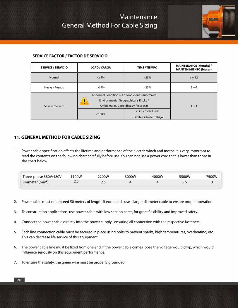
11. GENERAL METHOD FOR CABLE SIZING
1. Power cable specification affects the lifetime and performance of the electric winch and motor. It is very important to read the contents on the following chart carefully before use. You can not use a power cord that is lower than those in the chart below.
2. Power cable must not exceed 50 meters of length, if exceeded , use a larger diameter cable to ensure proper operation.
3. To construction applications, use power cable with low section cores, for great flexibility and improved safety.
4. Connect the power cable directly into the power supply , ensuring all connection with the respective fasteners.
5. Each line connection cable must be secured in place using bolts to prevent sparks, high temperatures, overheating, etc. This can decrease life service of this equipment.
6. The power cable line must be fixed from one end. If the power cable comes loose the voltage would drop, which would influence seriously on this equipment performance.
7. To ensure the safety, the green wire must be properly grounded.
Maintenance General Method For Cable Sizing
Three-phase 380V/480VDiameter (mm²)
1100W2.5
2200W2.5
3000W4
4000W4
5500W5.5
7500W8
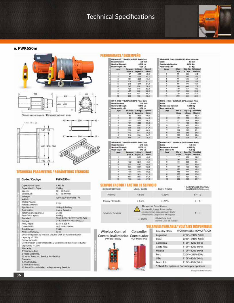
SERVICE / SERVICIO LOAD / CARGA TIME / TIEMPO MAINTENANCE (Months) / MANTENIMIENTO (Meses)
Normal <65% <25% 6 ~ 12
Heavy / Pesado >65% >25% 3 ~ 6
Severe / Severo
Abnormal Conditions / En condiciones Anormales
Environmental Geographical y Riscky /
Ambientales, Geográficas y Riesgosas 1 ~ 3
<100%<Duty Cycle Limit
>Límite Ciclo de Trabajo
SERVICE FACTOR / FACTOR DE SERVICIO
21
12. SAFETY USE
1. To install and use this equipment should consider safety as the first principle.
2. This equipment must be operated by a qualified worker with knowledge in Industrial safety.
3. When the machine is in use, the staff can not use the framework hook , lifting platform for other work or remain under the equipment or load.
4. Do not repair or modify this equipment without authorization of Prowinch . Replacement parts and service must be performed in Prowinch.
5. This equipment must be operated with empty load before using each time, to check the following actions: a. Whether the switch is flexible, the control switch coincides with the operation of the equipment, lifting and lowering the load, and can be stopped at any time. b. Whether there are unusual noises while operating. c. Whether the wire or/and chain has any visual damage. If there is damage, please stop the operation and change it immediately to guarantee safety. d. Never operate winch with less than three (3) wraps of rope around the drum. Rope could come loose from the drum, as the rope attachment to the drum is not designed to hold a load. e. Whether the fastener of every position of machine becomes flexible.
6. Please use according to this instructions and recommendations. Also follow the recomendations for voltage and rate load. Never exceed equipment or rope rated capacity.
7. Always wear heavy leather gloves when handling winch rope.
8. Never use winch as a hoist or to suspend a load.
9. Do not apply the load to the tip of the hook or to the hook latch.
10. Do not keep hanging loaded objects for long periods of time.
11. Do not use the equipment to lift or move people.
12. While changing the steel wire rope, must pay attention to the head of steel wire rope.
13. Attention: the motor work system of this electric winch is S3-25% 20min (one duty cycle is 20 minutes, work for five minutes, let the equipment rest for 15 minutes).
Safety Use

22
Installation and Testing
13. INSTALLATION AND TESTING
1. Installation Attachments and anchorages of this equipment must provide a balanced mounting and be capable of withstanding loads imposed by the equipment under operating conditions. It is the installer or/and owner’s responsibility to carry out all structural tests to ensure proper installation. Prowinch® is not responsible of improper installations.
2. Testing a. Whether the working voltage of testing installation site accords with the demand stipulated on the data plate of the products, lest makes the machine burn out because the power sends mistake, its voltage should be range in specified value ± 10% . b. Whether the circuit of the electric apparatus connection reliable, the direction of the rising and dropping should according to the direction of the switch. c. Unload testing ----Hoisting or lower the number of times, there can’t be vibration and unusual sound. d. The load is testing ---Go up and down rated load for several times, check machinery its rotate, electric attachment and connection normal and reliable. e. When the rated load drops, applies the brake hang in the air , its gliding amount should not exceed 1 of the length of the steel wire rope involved in for less than one minute1.5%
13.1 Maintenance of Winch
1. This machine adopts the planet gear to speed down power of transfer , it is guarantee have good lubricate state, please put grease to lubricate in the filler hole in every three months.
2. Steel wire rope is for go up and down contained article, if get rusty or rainwater corrode, please pull out the whole steel wire rope and wipe the lubricate grease and keep maintain.
3. The electric winch should be followed and used the frequent degree. Overhaul in an all-round way through certain time, should generally go on once every year.
23
Common Trouble And Solutions
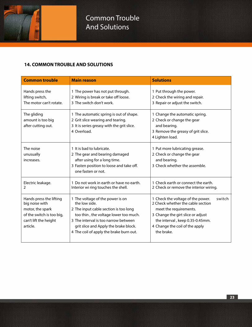
14. COMMON TROUBLE AND SOLUTIONS
Common trouble Main reason Solutions
Hands press the 1 The power has not put through. 1 Put through the power. lifting switch, 2 Wiring is break or take off loose. 2 Check the wiring and repair.The motor can’t rotate. 3 The switch don’t work. 3 Repair or adjust the switch.
The gliding 1 The automatic spring is out of shape. 1 Change the automatic spring.amount is too big 2 Grit slice wearing and tearing. 2 Check or change the gearafter cutting out. 3 It is series greasy with the grit slice. and bearing. 4 Overload. 3 Remove the greasy of grit slice. 4 Lighten load.
The noise 1 It is bad to lubricate. 1 Put more lubricating grease.unusually 2 The gear and bearing damaged 2 Check or change the gear increases. after using for a long time. and bearing. 3 Fasten position to loose and take off. 3 Check whether the assemble. one fasten or not.
Electric leakage. 1 Do not work in earth or have no earth. 1 Check earth or connect the earth. 2 Interior wi ring touches the shell. 2 Check or remove the interior wiring. Hands press the lifting 1 The voltage of the power is on 1 Check the voltage of the power. switch big noise with the low side. 2 Check whether the cable sectionmotor, the spark 2 The input cable section is too long meet the requirements.of the switch is too big, too thin , the voltage lower too much. 3 Change the girt slice or adjustcan’t lift the height 3 The interval is too narrow between the interval , keep 0.35-0.45mm.article. grit slice and Apply the brake block. 4 Change the coil of the apply 4 The coil of apply the brake burn out. the brake.
24
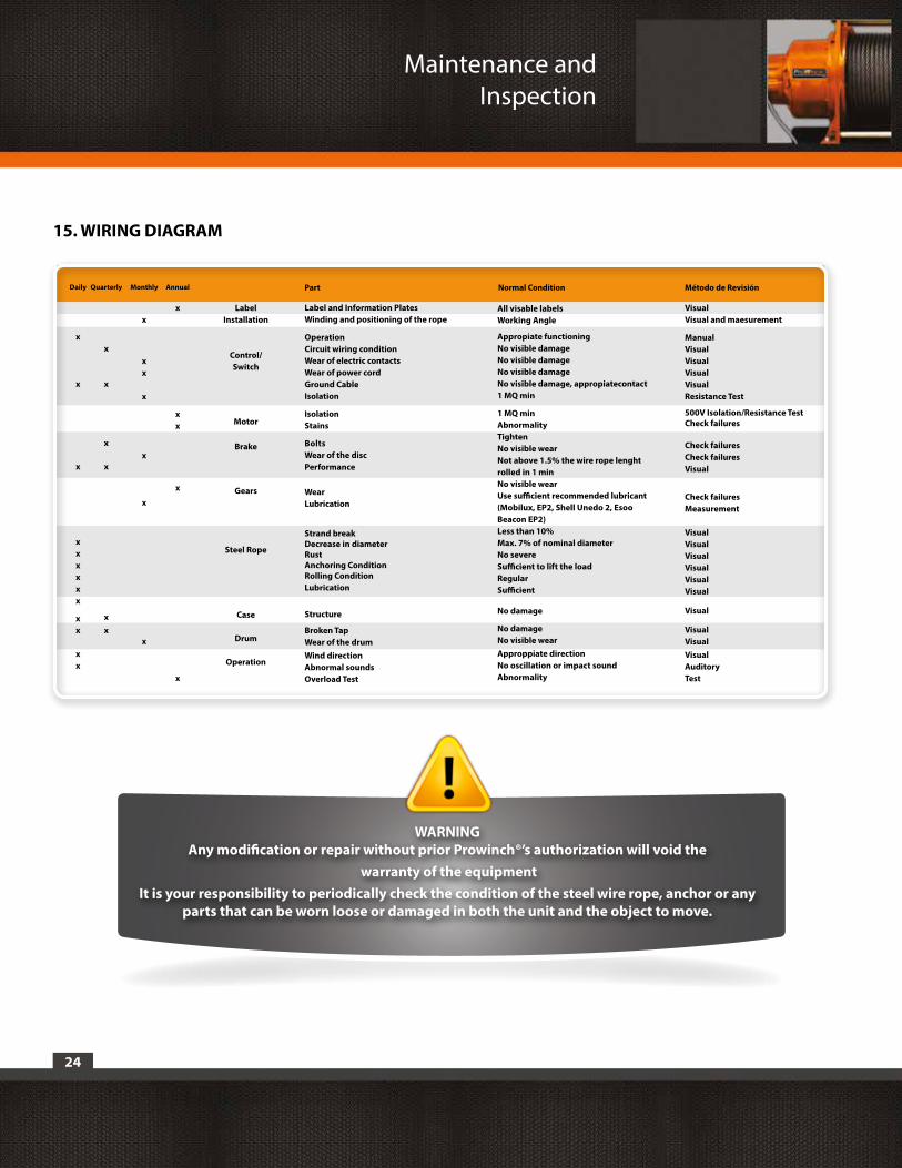
WARNING Any modification or repair without prior Prowinch®’s authorization will void the
warranty of the equipmentIt is your responsibility to periodically check the condition of the steel wire rope, anchor or any
parts that can be worn loose or damaged in both the unit and the object to move.
Maintenance and Inspection
15. WIRING DIAGRAM
Daily Quarterly Part Normal Condition Método de RevisiónMonthly Annual
VisualVisual and maesurement
ManualVisualVisualVisualVisualResistance Test
500V Isolation/Resistance TestCheck failures
Check failuresCheck failuresVisual
Check failuresMeasurement
VisualVisualVisualVisualVisualVisual
Visual
VisualVisualVisualAuditoryTest
x
x
x
x
xx
x
xx
x
x
x
x
Label Installation
Control/ Switch
Motor
Brake
Gears
Steel Rope
Case
Drum
Operation
x
x
x
xxxxxx
xx
xx
x
xx
x
x
Label and Information PlatesWinding and positioning of the rope
OperationCircuit wiring conditionWear of electric contactsWear of power cordGround CableIsolation
IsolationStains
BoltsWear of the discPerformance
WearLubrication
Strand breakDecrease in diameterRustAnchoring ConditionRolling ConditionLubrication
Structure
Broken TapWear of the drumWind directionAbnormal soundsOverload Test
All visable labels Working Angle
Appropiate functioningNo visible damageNo visible damageNo visible damageNo visible damage, appropiatecontact1 MQ min
1 MQ minAbnormalityTightenNo visible wearNot above 1.5% the wire rope lenght rolled in 1 minNo visible wearUse sufficient recommended lubricant (Mobilux, EP2, Shell Unedo 2, Esoo Beacon EP2)Less than 10%Max. 7% of nominal diameterNo severeSufficient to lift the loadRegularSufficient
No damage
No damageNo visible wearApproppiate directionNo oscillation or impact soundAbnormality
25
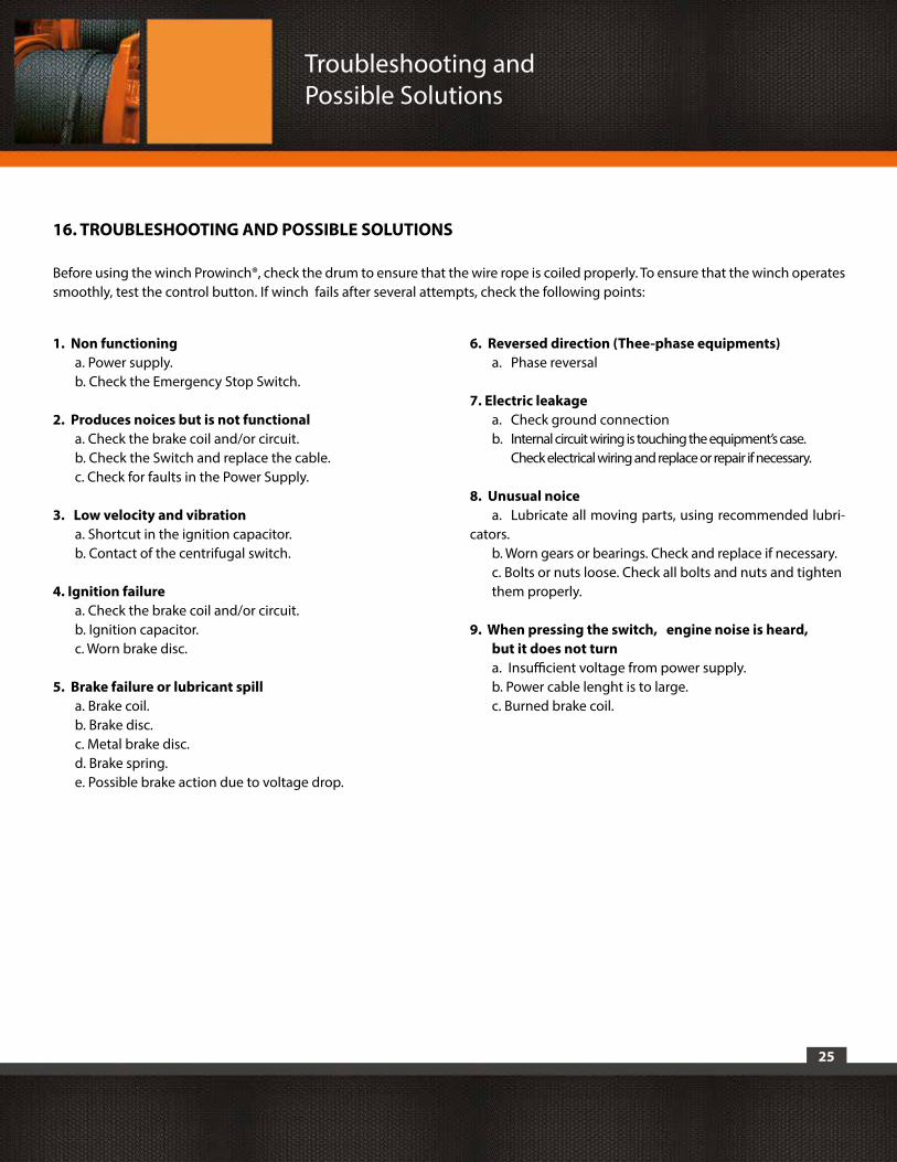
1. Non functioning a. Power supply. b. Check the Emergency Stop Switch.
2. Produces noices but is not functional a. Check the brake coil and/or circuit. b. Check the Switch and replace the cable. c. Check for faults in the Power Supply.
3. Low velocity and vibration a. Shortcut in the ignition capacitor. b. Contact of the centrifugal switch.
4. Ignition failure a. Check the brake coil and/or circuit. b. Ignition capacitor. c. Worn brake disc.
5. Brake failure or lubricant spill a. Brake coil. b. Brake disc. c. Metal brake disc. d. Brake spring. e. Possible brake action due to voltage drop.
6. Reversed direction (Thee-phase equipments) a. Phase reversal
7. Electric leakage a. Check ground connection b. Internal circuit wiring is touching the equipment’s case. Check electrical wiring and replace or repair if necessary.
8. Unusual noice a. Lubricate all moving parts, using recommended lubri-cators. b. Worn gears or bearings. Check and replace if necessary. c. Bolts or nuts loose. Check all bolts and nuts and tighten them properly.
9. When pressing the switch, engine noise is heard, but it does not turn a. Insufficient voltage from power supply. b. Power cable lenght is to large. c. Burned brake coil.
16. TROUBLESHOOTING AND POSSIBLE SOLUTIONS
Before using the winch Prowinch®, check the drum to ensure that the wire rope is coiled properly. To ensure that the winch operates smoothly, test the control button. If winch fails after several attempts, check the following points:
Troubleshooting and Possible Solutions
26
1) Warranty is only valid with the receipt or legal invoice for a period of 3 years from it’s issue date and with the Prowinch maintenance up to date (yearly)
2) This lifting equipment, even though it was designed to lift or pull weight, it’s not designed lo lift people or similar objects. People must keep away from the wire rope (or chain), hook and load.
3) It’s user’s responsibility to install the unit by certified personnel who are fully capable of performing that labor by the norms. Every structural calculation must be done by a calculation engineer accredited who must certify the installation. A wrong installation process will invalidate the unit’s warranty.
4) Is responsibility of every person who uses the equipment, to operate according to ASME B30 norms. Is also responsible for doing and keeping record of maintenance donde to the equipment. Prowinch offers training and certifies operators.
5) In case of performing any electric connection that differs from the user’s manual, the warranty will immediately expire.
6) The equipment owner is responsible for checking regularly the wire rope (or chain), hook or any other piece of the equipment that may be loose or damaged, on the equipment or the load to be manipulated.
7) The user is responsible for wearing the safety equipment indicated in the manual for the operation of this equipment. Strong globes, working helmet, safety shoes and eye glasses protection. This applies for any person surrounding the equipment.
8) The warranty will expire immediately if any type of intervention is done to the equipment.
9) Every Prowinch equipment has a warranty seal. In case it is broken, warranty will expire immediately.
10) Warranty will end if equipment in not installed in an adequate levelled surface and without the right perforations and anchorages.
11) It’s user’s responsibility to comply with the right electrical specifications of the equipment.
12) This warranty only covers fabrication defects.
13) Every unit that may show signs of abuse, loading more than the indicated weight, has evidence of burned circuits, has broken or damaged parts will not be covered for this warranty.
14) It’s users responsibility not to overload the equipment above the weight indicated on the nameplate of the unit.
17. WARRANTY
Warranty
27
15) This warranty is given within Prowinch headquarters. Replacement parts covered by this warranty are sent to destination. Shipping and handling costs are not included and must be paid by the owner.
16) Warranty does not cover equipment transportation, unloading, personnel transportation or any other cost that may be related to not using the equipment.
17) In case a technical visit is solicited and scheduled at customers site, it shall be paid in advance even though the visit involves services covered by this warranty.
18) The warranty is only valid to the direct buyer, not to other people in case of resale, renting or passing the equipment to others.
Warranty exclusions:
- If the damage is produced by meteorological agents.
- If the damage is produced by external agents such as: fire, water, crushing, wrong voltage usage or inadequate energy use.
- If any damage is caused by inadequate transportation, vandalism, sand or natural disasters such as earthquakes, flood or fire.
Warranty

18. ESPECIFICACIONES TÉCNICAS
a. Winche PWK380
28
Technical Specifications
29
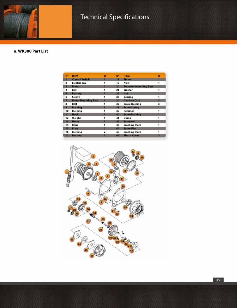
a. WK380 Part List
Technical Specifications
Nº ITEM Q Nº ITEM Q1 Control Switch 1 18 Pinion 12 Electric Box 1 19 Axle 13 Motor 1 20 Reductor Mounting Base 14 Key 1 21 Washer 15 Bearing 1 22 Nut 16 Sleeve 1 23 Bearing 17 Motor Mounting Base 1 24 Gearbox Case 38 Bolt 1 37 Brake Bushing 39 Bushing 3 38 Brake Spring 110 Bushing 1 39 Retainer 111 Hook 1 40 Brake Bushing 112 Weight 1 41 O ring 113 Drum 1 42 Brake coil 114 Rope 1 43 Bracking Plate 115 Plate 2 44 Brake Disc 116 Bushing 2 45 Bracking Plate 117 Bearing 2 46 Plastic Cover 2
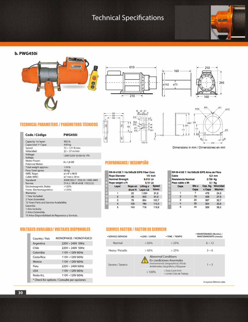
b. PWG450i
Technical Specifications
30
31
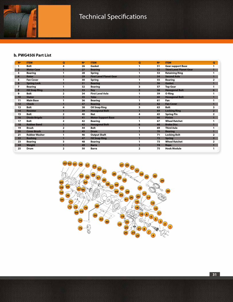
b. PWG450i Part List
Technical Specifications
Nº ITEM Q Nº ITEM Q Nº ITEM Q1 Bolt 4 26 Gasket 1 51 Gear support Base 12 Motor Case 1 27 Bearing 1 52 Third Level Planet Gear 13 Bearing 1 28 Spring 1 53 Retaining Ring 14 Rotor 1 29 First Level Planet Gear 1 54 Second Axle 15 Fan Cover 1 30 Spring 1 55 Bearing 26 Spring Lock 1 31 Bearing 1 56 Gasket 17 Bearing 1 32 Bearing 3 57 Top Gear 18 Oil Snap Ring 1 33 Key 3 58 Hexagonal Bolt 69 Bolt 2 34 First Level Axle 1 59 O-Ring 110 Stator 1 35 Yoke 1 60 Hexagonal Bolt 111 Main Base 1 36 Bearing 1 61 Fan 112 Check 1 37 Bearing 2 62 Fan Cover 113 Bolt 4 38 Oil Snap Ring 3 63 Bolt 314 Resistor 1 39 Hexagonal Bolt 1 64 Locking Ring 215 Bolt 2 40 Nut 4 65 Spring Pin 216 Diode Brigde 2 41 Motor Support Base 1 66 Pinion 117 Bolt 2 42 Bearing 1 67 Wheel Ratchet 118 Rubber Band 1 43 Hexagonal Bolt 6 68 Brake Disc 119 Brush 2 44 Bolt 1 69 Third Axle 120 Cover Brush 2 45 Drum 1 70 Bearing 121 Rubber Washer 1 46 Output Shaft 1 71 Locking Bolt 222 Bushing 1 47 Oil Snap Ring 1 72 Spring 223 Bearing 3 48 Bearing 1 73 Wheel Ratchet 224 Weight 1 49 Barra 1 74 Rope 125 Drum 2 50 Barra 2 75 Hook Module 1

Technical Specifications
32
c. PWK500

33
c. PWK500
PWK500 Part List
1 6
2021 22 23
1918171615141312
7 8 9 10 112 3 4 5
Technical Specifications
Nº ITEM Q1 Circlip 12 Washer 13 Bearing 24 Drum 15 Rope Nut 16 Spacer 17 Pinion - 4 18 Pinion - 2 19 Pinion - 3 110 Axle 111 Bearing 212 Motor 113 Nut 614 Support Plate 115 Screw Tight 316 IWRC Rope 117 Support Plate 118 B bolt and Grower Washer 419 Cover Reductor 120 Circlip 121 Bearing Cover 122 C Bolt 423 Bolt and Grower Washer 10
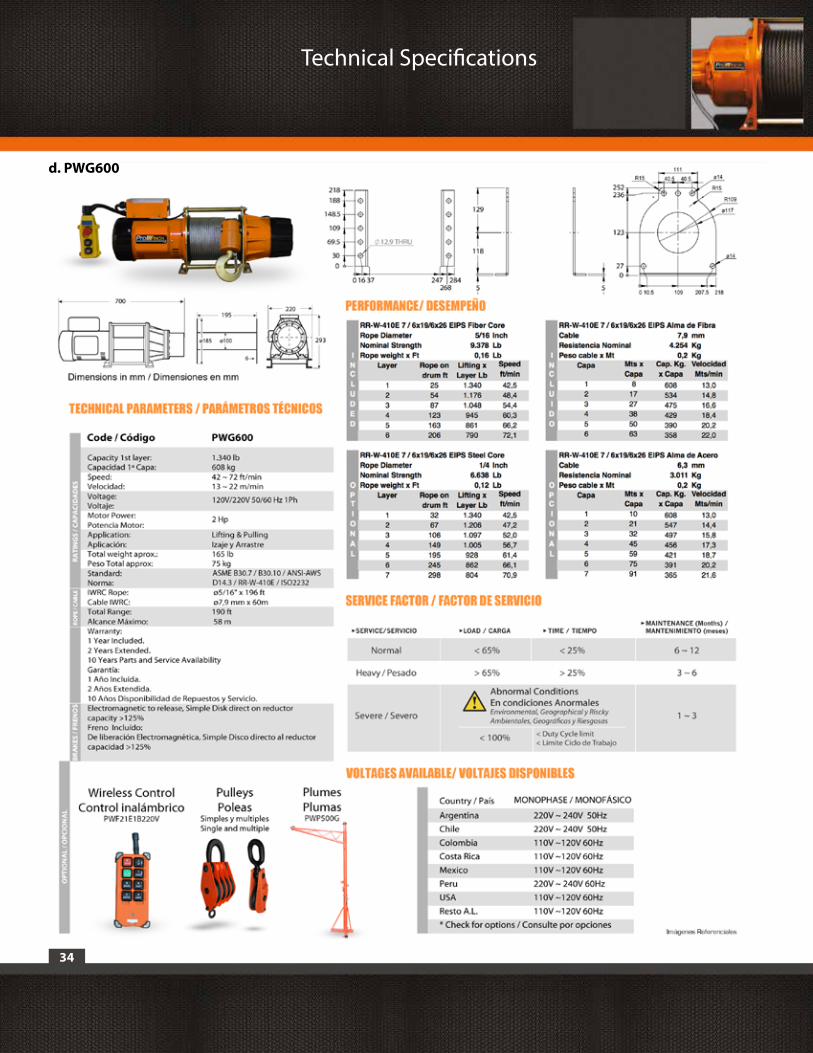
d. PWG600
34
Technical Specifications
35
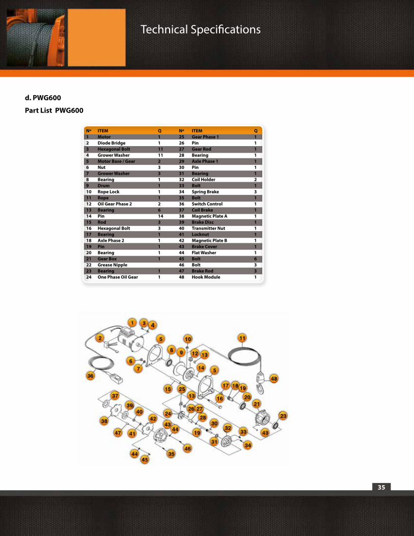
d. PWG600
Part List PWG600
Technical Specifications
Nº ITEM Q Nº ITEM Q1 Motor 1 25 Gear Phase 1 12 Diode Bridge 1 26 Pin 13 Hexagonal Bolt 11 27 Gear Rod 14 Grower Washer 11 28 Bearing 15 Motor Base / Gear 2 29 Axle Phase 1 16 Nut 3 30 Pin 17 Grower Washer 3 31 Bearing 18 Bearing 1 32 Coil Holder 29 Drum 1 33 Bolt 110 Rope Lock 1 34 Spring Brake 311 Rope 1 35 Bolt 112 Oil Gear Phase 2 2 36 Switch Control 113 Bearing 6 37 Coil Brake 114 Pin 14 38 Magnetic Plate A 115 Rod 3 39 Brake Disc 116 Hexagonal Bolt 3 40 Transmitter Nut 117 Bearing 1 41 Locknut 118 Axle Phase 2 1 42 Magnetic Plate B 119 Pin 1 43 Brake Cover 120 Bearing 1 44 Flat Washer 121 Gear Box 1 45 Bolt 622 Grease Nipple 46 Bolt 323 Bearing 1 47 Brake Rod 324 One Phase Oil Gear 1 48 Hook Module 1
36
e. PWK650m
Technical Specifications
37
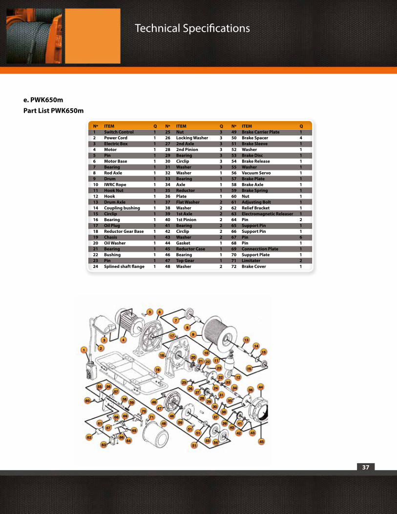
e. PWK650mPart List PWK650m
Technical Specifications
Nº ITEM Q Nº ITEM Q Nº ITEM Q1 Switch Control 1 25 Nut 3 49 Brake Carrier Plate 12 Power Cord 1 26 Locking Washer 3 50 Brake Spacer 43 Electric Box 1 27 2nd Axle 3 51 Brake Sleeve 14 Motor 1 28 2nd Pinion 3 52 Washer 15 Pin 1 29 Bearing 3 53 Brake Disc 16 Motor Base 1 30 Circlip 3 54 Brake Release 17 Bearing 1 31 Washer 3 55 Washer 18 Rod Axle 1 32 Washer 1 56 Vacuum Servo 19 Drum 1 33 Bearing 1 57 Brake Plate 110 IWRC Rope 1 34 Axle 1 58 Brake Axle 111 Hook Nut 1 35 Reductor 1 59 Brake Spring 112 Hook 1 36 Plate 1 60 Nut 113 Drum Axle 1 37 Flat Washer 2 61 Adjusting Bolt 114 Coupling bushing 1 38 Washer 2 62 Relief Bracket 115 Circlip 1 39 1st Axle 2 63 Electromagnetic Releaser 116 Bearing 1 40 1st Pinion 2 64 Pin 217 Oil Plug 1 41 Bearing 2 65 Support Pin 118 Reductor Gear Base 1 42 Circlip 2 66 Support Pin 119 Chasis 1 43 Washer 2 67 Pin 620 Oil Washer 1 44 Gasket 1 68 Pin 121 Bearing 1 45 Reductor Case 1 69 Connecction Plate 122 Bushing 1 46 Bearing 1 70 Support Plate 123 Pin 1 47 Top Gear 1 71 Limitater 224 Splined shaft flange 1 48 Washer 2 72 Brake Cover 1

f. PWK1250
38
Technical Specifications
39
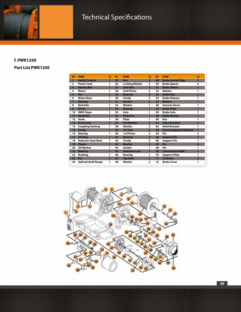
f. PWK1250
Part List PWK1250
Technical Specifications
Nº ITEM Q Nº ITEM Q Nº ITEM Q1 Switch Control 1 25 Nut 3 49 Brake Carrier Plate 12 Power Cord 1 26 Locking Washer 3 50 Brake Spacer 43 Electric Box 1 27 2nd Axle 3 51 Brake Sleeve 14 Motor 1 28 2nd Pinion 3 52 Washer 15 Pin 1 29 Bearing 3 53 Brake Disc 16 Motor Base 1 30 Circlip 3 54 Brake Release 17 Bearing 1 31 Washer 3 55 Washer 18 Rod Axle 1 32 Washer 1 56 Vacuum Servo 19 Drum 1 33 Bearing 1 57 Brake Plate 110 IWRC Rope 1 34 Axle 1 58 Brake Axle 111 Hook Nut 1 35 Reductor 1 59 Brake Spring 112 Hook 1 36 Plate 1 60 Nut 113 Drum Axle 1 37 Flat Washer 2 61 Adjusting Bolt 114 Coupling bushing 1 38 Washer 2 62 Relief Bracket 115 Circlip 1 39 1st Axle 2 63 Electromagnetic Releaser 116 Bearing 1 40 1st Pinion 2 64 Pin 217 Oil Plug 1 41 Bearing 2 65 Support Pin 118 Reductor Gear Base 1 42 Circlip 2 66 Support Pin 119 Chasis 1 43 Washer 2 67 Pin 620 Oil Washer 1 44 Gasket 1 68 Pin 121 Bearing 1 45 Reductor Case 1 69 Connecction Plate 122 Bushing 1 46 Bearing 1 70 Support Plate 123 Pin 1 47 Top Gear 1 71 Limitater 224 Splined shaft flange 1 48 Washer 2 72 Brake Cover 1
40
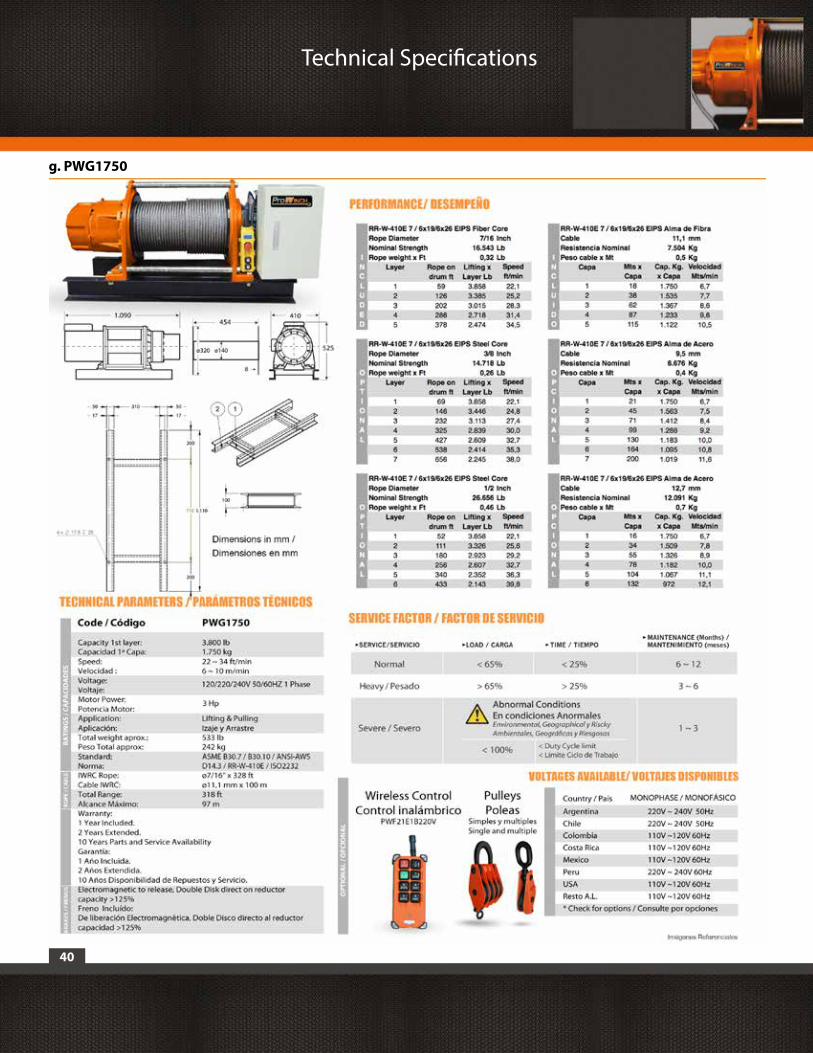
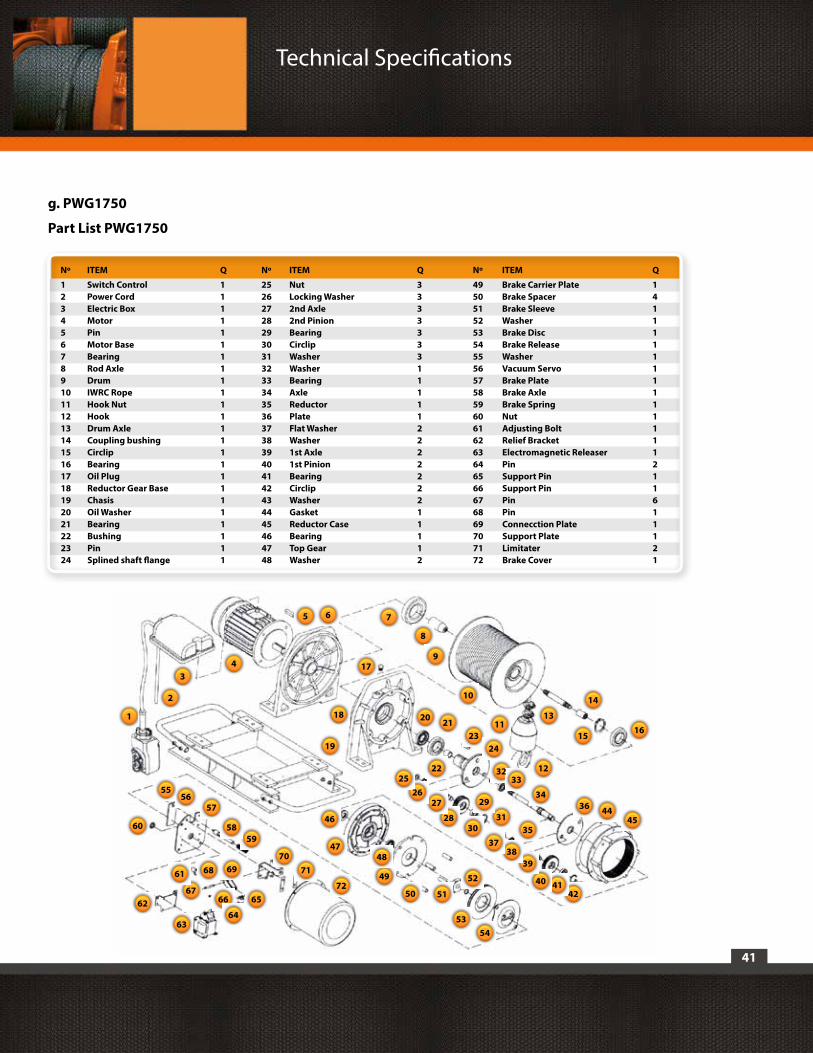
g. PWG1750
Technical Specifications
41
g. PWG1750
Part List PWG1750
Technical Specifications
23
4544
424140
3938
37
36
35
34
3233
3130
29
28
2726
25
24
20 21
22
19
18
17
1615
14
13
12
11
10
8
765
43
2
1
5453
52
5150
49
4847
46
72
7170
6968
6766 65
6463
62
61
6059
58
5756
55
9
Nº ITEM Q Nº ITEM Q Nº ITEM Q
1 Switch Control 1 25 Nut 3 49 Brake Carrier Plate 12 Power Cord 1 26 Locking Washer 3 50 Brake Spacer 43 Electric Box 1 27 2nd Axle 3 51 Brake Sleeve 14 Motor 1 28 2nd Pinion 3 52 Washer 15 Pin 1 29 Bearing 3 53 Brake Disc 16 Motor Base 1 30 Circlip 3 54 Brake Release 17 Bearing 1 31 Washer 3 55 Washer 18 Rod Axle 1 32 Washer 1 56 Vacuum Servo 19 Drum 1 33 Bearing 1 57 Brake Plate 110 IWRC Rope 1 34 Axle 1 58 Brake Axle 111 Hook Nut 1 35 Reductor 1 59 Brake Spring 112 Hook 1 36 Plate 1 60 Nut 113 Drum Axle 1 37 Flat Washer 2 61 Adjusting Bolt 114 Coupling bushing 1 38 Washer 2 62 Relief Bracket 115 Circlip 1 39 1st Axle 2 63 Electromagnetic Releaser 116 Bearing 1 40 1st Pinion 2 64 Pin 217 Oil Plug 1 41 Bearing 2 65 Support Pin 118 Reductor Gear Base 1 42 Circlip 2 66 Support Pin 119 Chasis 1 43 Washer 2 67 Pin 620 Oil Washer 1 44 Gasket 1 68 Pin 121 Bearing 1 45 Reductor Case 1 69 Connecction Plate 122 Bushing 1 46 Bearing 1 70 Support Plate 123 Pin 1 47 Top Gear 1 71 Limitater 224 Splined shaft flange 1 48 Washer 2 72 Brake Cover 1

42
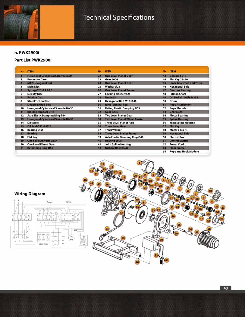
h. PWK2900i
Technical Specifications
43
h. PWK2900i
Part List PWK2900i
Technical Specifications
1 3 5 A1 21
STOP
FOR.
REV.
R S T
V13 OAC
BRAKE
BLUE
0 24V
Wiring Diagram
Forward Reverse
2 4 6 A2 22
1 3 5 A1 21
2 4 6 A2 22
1 3 5 A1 21
2 4 6 A2 22
1 3 5 95
2 4 6 96V2
V1
V2
V1
V2
0 24V3 0 240V MOTOR
Nº ITEM Nº ITEM Nº ITEM
1 Hexagonal Cylindrical Screw M8x20 22 One Level Planet Gear 43 Bearing 60172 Protective Case 23 Gear 6006 44 Flat Key 22x803 M12 Hexagonal Nut 24 One Level Planet Gear 45 Inner Gear (Two and Three)4 Main Disc 25 Washer Ø25 46 Hexagonal Bolt5 Spring Ø20x25 Ø2,6 26 One Level Planet Frame 47 Gearbox Bearing6 Deputy Disc 27 Locking Washer Ø25 48 Pitman Shaft7 Friction Disc 28 Nut M25 49 Oil Seal Ø120Ø85x155 8 Steel Friction Disc 29 Hexagonal Bolt M10x140 50 Drum9 Double Ended Bolt 30 Ring Terminal Pad 51 Rope Attachment10 Hexagonal Cylindrical Screw M10x30 31 Rating Elastic Damping Ø65 52 Rope Module11 Braking Support Disc 32 Gear 6206 53 Gear 602112 Axle Elastic Damping Ring Ø34 33 Two Level Planet Gear 54 Motor Bearing13 Hexagonal Cylindrical Screw M10x30 34 Two Level Planet Wheel Carrier 55 Spline Housing14 Disc Axle 35 Three Level Planet Axle 56 Joint Spline Housing15 Oil Seal Ø55x8 Ø35 36 Three Level Gear 57 Flat Key16 Bearing Disc 37 Thick Washer 58 Motor Y132-417 Bearing 38 Three Level Planet Frame 59 Hexagonal Bolt18 Flat Key 39 Axle Elastic Damping Ring Ø40 60 Electric Box19 One Level Annular Gear 40 Bearing 6008 61 Control Switch20 One Level Planet Gear 41 Joint Spline Housing 62 Power Cord21 Retainning Ring Ø55 42 Oil Seal Ø55x35x8 63 Floor Frame 64 Rope and Hook Module
44
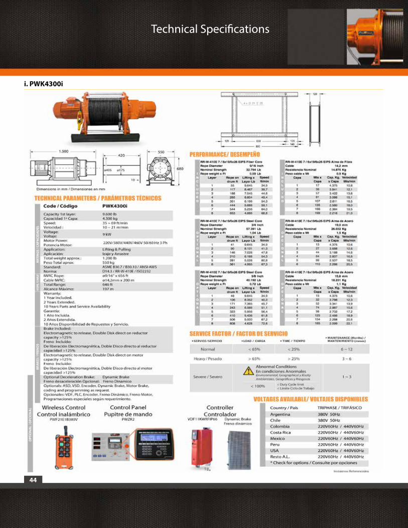
i. PWK4300i
Technical Specifications
45
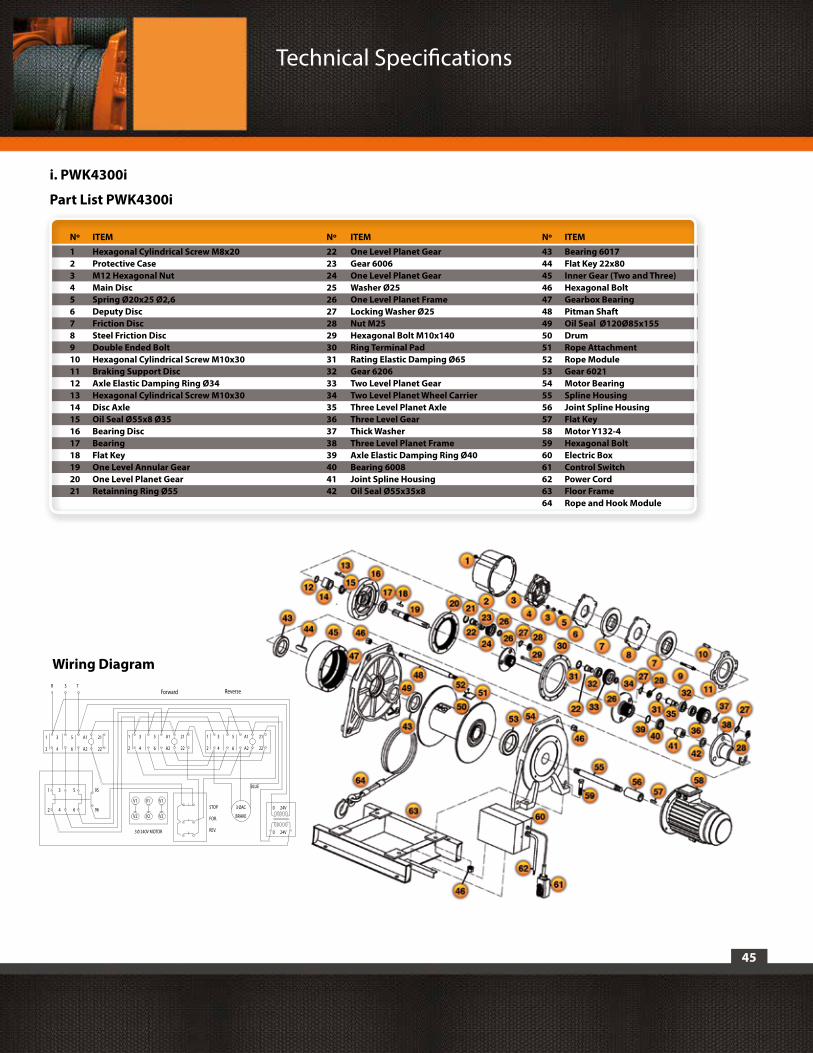
i. PWK4300i
Part List PWK4300i
Technical Specifications
1 3 5 A1 21
STOP
FOR.
REV.
R S T
V13 OAC
BRAKE
BLUE
0 24V
Wiring Diagram
Forward Reverse
2 4 6 A2 22
1 3 5 A1 21
2 4 6 A2 22
1 3 5 A1 21
2 4 6 A2 22
1 3 5 95
2 4 6 96V2
V1
V2
V1
V2
0 24V3 0 240V MOTOR
Nº ITEM Nº ITEM Nº ITEM
1 Hexagonal Cylindrical Screw M8x20 22 One Level Planet Gear 43 Bearing 60172 Protective Case 23 Gear 6006 44 Flat Key 22x803 M12 Hexagonal Nut 24 One Level Planet Gear 45 Inner Gear (Two and Three)4 Main Disc 25 Washer Ø25 46 Hexagonal Bolt5 Spring Ø20x25 Ø2,6 26 One Level Planet Frame 47 Gearbox Bearing6 Deputy Disc 27 Locking Washer Ø25 48 Pitman Shaft7 Friction Disc 28 Nut M25 49 Oil Seal Ø120Ø85x155 8 Steel Friction Disc 29 Hexagonal Bolt M10x140 50 Drum9 Double Ended Bolt 30 Ring Terminal Pad 51 Rope Attachment10 Hexagonal Cylindrical Screw M10x30 31 Rating Elastic Damping Ø65 52 Rope Module11 Braking Support Disc 32 Gear 6206 53 Gear 602112 Axle Elastic Damping Ring Ø34 33 Two Level Planet Gear 54 Motor Bearing13 Hexagonal Cylindrical Screw M10x30 34 Two Level Planet Wheel Carrier 55 Spline Housing14 Disc Axle 35 Three Level Planet Axle 56 Joint Spline Housing15 Oil Seal Ø55x8 Ø35 36 Three Level Gear 57 Flat Key16 Bearing Disc 37 Thick Washer 58 Motor Y132-417 Bearing 38 Three Level Planet Frame 59 Hexagonal Bolt18 Flat Key 39 Axle Elastic Damping Ring Ø40 60 Electric Box19 One Level Annular Gear 40 Bearing 6008 61 Control Switch20 One Level Planet Gear 41 Joint Spline Housing 62 Power Cord21 Retainning Ring Ø55 42 Oil Seal Ø55x35x8 63 Floor Frame 64 Rope and Hook Module

j. PWG7700
46
Technical Specifications

47
j. PWG7700
Part List PWG7700
Technical Specifications
1 3 5 A1 21
STOP
FOR.
REV.
R S T
V13 OAC
BRAKE
BLUE
0 24V
Wiring Diagram
Forward Reverse
2 4 6 A2 22
1 3 5 A1 21
2 4 6 A2 22
1 3 5 A1 21
2 4 6 A2 22
1 3 5 95
2 4 6 96V2
V1
V2
V1
V2
0 24V3 0 240V MOTOR
Nº ITEM Nº ITEM Nº ITEM
1 Hexagonal Cylindrical Screw M8x20 22 One Level Planet Gear 43 Bearing 60172 Protective Case 23 Gear 6006 44 Flat Key 22x803 M12 Hexagonal Nut 24 One Level Planet Gear 45 Inner Gear (Two and Three)4 Main Disc 25 Washer Ø25 46 Hexagonal Bolt5 Spring Ø20x25 Ø2,6 26 One Level Planet Frame 47 Gearbox Bearing6 Deputy Disc 27 Locking Washer Ø25 48 Pitman Shaft7 Friction Disc 28 Nut M25 49 Oil Seal Ø120Ø85x155 8 Steel Friction Disc 29 Hexagonal Bolt M10x140 50 Drum9 Double Ended Bolt 30 Ring Terminal Pad 51 Rope Attachment10 Hexagonal Cylindrical Screw M10x30 31 Rating Elastic Damping Ø65 52 Rope Module11 Braking Support Disc 32 Gear 6206 53 Gear 602112 Axle Elastic Damping Ring Ø34 33 Two Level Planet Gear 54 Motor Bearing13 Hexagonal Cylindrical Screw M10x30 34 Two Level Planet Wheel Carrier 55 Spline Housing14 Disc Axle 35 Three Level Planet Axle 56 Joint Spline Housing15 Oil Seal Ø55x8 Ø35 36 Three Level Gear 57 Flat Key16 Bearing Disc 37 Thick Washer 58 Motor Y132-417 Bearing 38 Three Level Planet Frame 59 Hexagonal Bolt18 Flat Key 39 Axle Elastic Damping Ring Ø40 60 Electric Box19 One Level Annular Gear 40 Bearing 6008 61 Control Switch20 One Level Planet Gear 41 Joint Spline Housing 62 Power Cord21 Retainning Ring Ø55 42 Oil Seal Ø55x35x8 63 Floor Frame 64 Rope and Hook Module

48
k. PWK12600
Technical Specifications
49
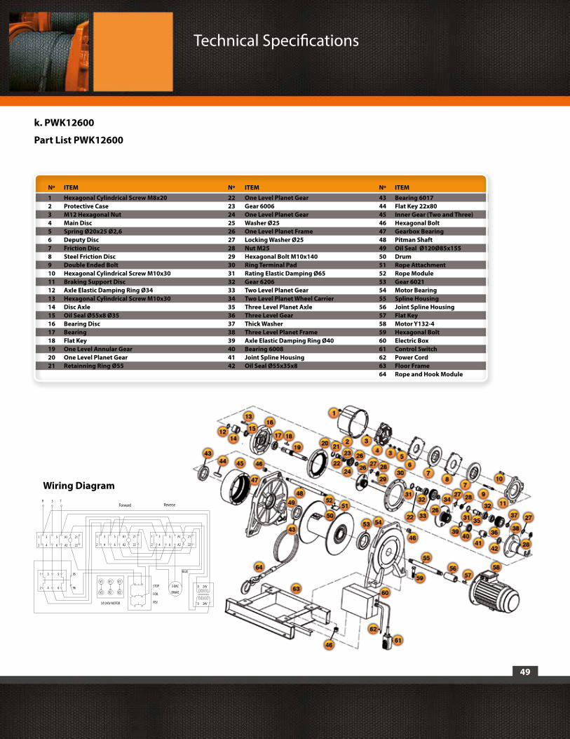
k. PWK12600
Part List PWK12600
Technical Specifications
1 3 5 A1 21
STOP
FOR.
REV.
R S T
V13 OAC
BRAKE
BLUE
0 24V
Wiring Diagram
Forward Reverse
2 4 6 A2 22
1 3 5 A1 21
2 4 6 A2 22
1 3 5 A1 21
2 4 6 A2 22
1 3 5 95
2 4 6 96V2
V1
V2
V1
V2
0 24V3 0 240V MOTOR
Nº ITEM Nº ITEM Nº ITEM
1 Hexagonal Cylindrical Screw M8x20 22 One Level Planet Gear 43 Bearing 60172 Protective Case 23 Gear 6006 44 Flat Key 22x803 M12 Hexagonal Nut 24 One Level Planet Gear 45 Inner Gear (Two and Three)4 Main Disc 25 Washer Ø25 46 Hexagonal Bolt5 Spring Ø20x25 Ø2,6 26 One Level Planet Frame 47 Gearbox Bearing6 Deputy Disc 27 Locking Washer Ø25 48 Pitman Shaft7 Friction Disc 28 Nut M25 49 Oil Seal Ø120Ø85x155 8 Steel Friction Disc 29 Hexagonal Bolt M10x140 50 Drum9 Double Ended Bolt 30 Ring Terminal Pad 51 Rope Attachment10 Hexagonal Cylindrical Screw M10x30 31 Rating Elastic Damping Ø65 52 Rope Module11 Braking Support Disc 32 Gear 6206 53 Gear 602112 Axle Elastic Damping Ring Ø34 33 Two Level Planet Gear 54 Motor Bearing13 Hexagonal Cylindrical Screw M10x30 34 Two Level Planet Wheel Carrier 55 Spline Housing14 Disc Axle 35 Three Level Planet Axle 56 Joint Spline Housing15 Oil Seal Ø55x8 Ø35 36 Three Level Gear 57 Flat Key16 Bearing Disc 37 Thick Washer 58 Motor Y132-417 Bearing 38 Three Level Planet Frame 59 Hexagonal Bolt18 Flat Key 39 Axle Elastic Damping Ring Ø40 60 Electric Box19 One Level Annular Gear 40 Bearing 6008 61 Control Switch20 One Level Planet Gear 41 Joint Spline Housing 62 Power Cord21 Retainning Ring Ø55 42 Oil Seal Ø55x35x8 63 Floor Frame 64 Rope and Hook Module

50
l. Winche PWK21000
Technical Specifications

51
Technical Specifications
PART LISTITEM PART
1 Induction Motor2 Sleeve3 Motor bearing4 Pitman shaft5 Bearing6 Bearing7 Hole elastic collar8 Drum9 Inner hexagonal sunk screw10 Rope Module11 Spline housing12 Reduction gearbox bearing13 Oil seal14 Bearing15 Flat key16 Three-level planet frame17 Round nut18 Washer I19 Bearing20 Three-level gear21 Hole elastic collar22 Three-level planet axle23 Joint spline housing24 Bearing25 Axle elastic collar26 Two-level planet wheel carrtier27 Washer II28 Two-level planet frame29 Two level planet shaft30 Bearing31 Hole elastic collar32 Two-level planet frame33 One-level annular gear34 Flat key35 Bearing36 Oil seal37 Washer III38 One-level planet frame39 Bearing40 Hole elastic collar41 One-level planet gear42 Two-three inner gear43 Ring terminal pad44 Spring washer45 Hexagonal cylindrical screw46 One level planet gear47 Bearing disk48 Hexagonal cylindrical screw49 Braking diamonds50 Axle elastic collar51 Friction disk52 Double ended bolt53 Steel friction disk54 Deputy disk55 Spring56 Main disk57 Hexagon nut58 Protecting hood59 Spring washer60 Hexagonal cylindrical screw61 Label62 Hexagonal bolt63 Spring washer64 Joint bolt65 Floor frame66 Spring Washer67 Hexagon nut
A A
B B
C C
D D
E E
F F
G G
H H
J J
K K
L L
M M
16
16
15
15
14
14
13
13
12
12
11
11
10
10
9
9
8
8
7
7
6
6
5
5
4
4
3
3
2
2
1
1
WINCHE IZAJE INDUSTRIAL21000kg
01PWK21000 A1
Equipos de Izaje Prowinch Chile Spa.Parque Riesco, 3407
Santiago - Chile
INTERPRET GEOMETRICAL TOLERANCING PER:
MATERIAL:
DIMENSIONS ARE IN MILLIMETERS.TOLERANCES: LINEAR: ± ANGULAR: ±
DO NOT SCALE DRAWING
FINISH:
UNLESS OTHERWISE SPECIFIED:
COMMENTS:
APPROVED:
PROJECT:
CHECKED:
DATENAME
DRAWN:
REV: SIZE:
WEIGHT: SHEET 1 OF 1SCALE:
CODE:
TITLE:
I. PWK21000
Part List PWK21000

52
Technical Specifications
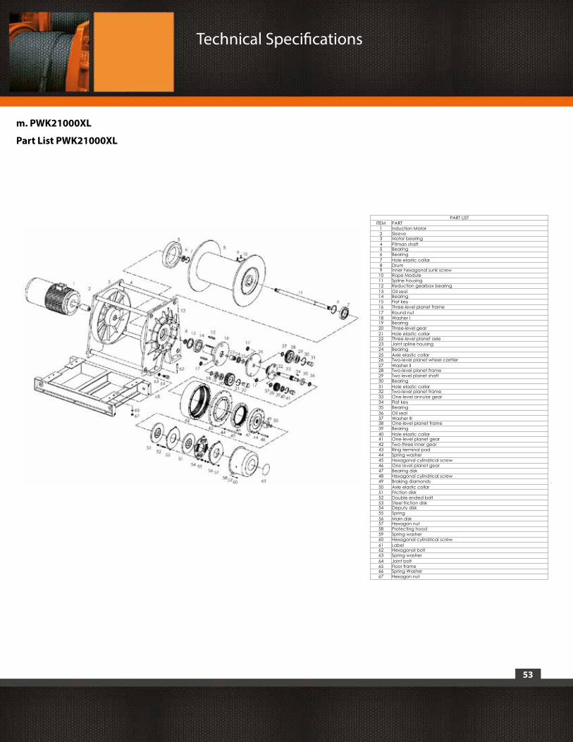
m. Winche PWK21000XL
53
Technical Specifications
PART LISTITEM PART
1 Induction Motor2 Sleeve3 Motor bearing4 Pitman shaft5 Bearing6 Bearing7 Hole elastic collar8 Drum9 Inner hexagonal sunk screw10 Rope Module11 Spline housing12 Reduction gearbox bearing13 Oil seal14 Bearing15 Flat key16 Three-level planet frame17 Round nut18 Washer I19 Bearing20 Three-level gear21 Hole elastic collar22 Three-level planet axle23 Joint spline housing24 Bearing25 Axle elastic collar26 Two-level planet wheel carrtier27 Washer II28 Two-level planet frame29 Two level planet shaft30 Bearing31 Hole elastic collar32 Two-level planet frame33 One-level annular gear34 Flat key35 Bearing36 Oil seal37 Washer III38 One-level planet frame39 Bearing40 Hole elastic collar41 One-level planet gear42 Two-three inner gear43 Ring terminal pad44 Spring washer45 Hexagonal cylindrical screw46 One level planet gear47 Bearing disk48 Hexagonal cylindrical screw49 Braking diamonds50 Axle elastic collar51 Friction disk52 Double ended bolt53 Steel friction disk54 Deputy disk55 Spring56 Main disk57 Hexagon nut58 Protecting hood59 Spring washer60 Hexagonal cylindrical screw61 Label62 Hexagonal bolt63 Spring washer64 Joint bolt65 Floor frame66 Spring Washer67 Hexagon nut
A A
B B
C C
D D
E E
F F
G G
H H
J J
K K
L L
M M
16
16
15
15
14
14
13
13
12
12
11
11
10
10
9
9
8
8
7
7
6
6
5
5
4
4
3
3
2
2
1
1
WINCHE IZAJE INDUSTRIAL21000kg
01PWK21000 A1
Equipos de Izaje Prowinch Chile Spa.Parque Riesco, 3407
Santiago - Chile
INTERPRET GEOMETRICAL TOLERANCING PER:
MATERIAL:
DIMENSIONS ARE IN MILLIMETERS.TOLERANCES: LINEAR: ± ANGULAR: ±
DO NOT SCALE DRAWING
FINISH:
UNLESS OTHERWISE SPECIFIED:
COMMENTS:
APPROVED:
PROJECT:
CHECKED:
DATENAME
DRAWN:
REV: SIZE:
WEIGHT: SHEET 1 OF 1SCALE:
CODE:
TITLE:
m. PWK21000XL
Part List PWK21000XL
54
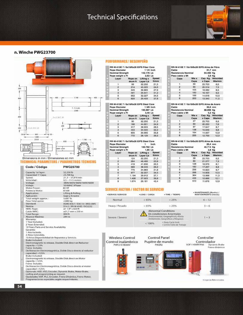
n. Winche PWG23700
Technical Specifications
55
Technical Specifications
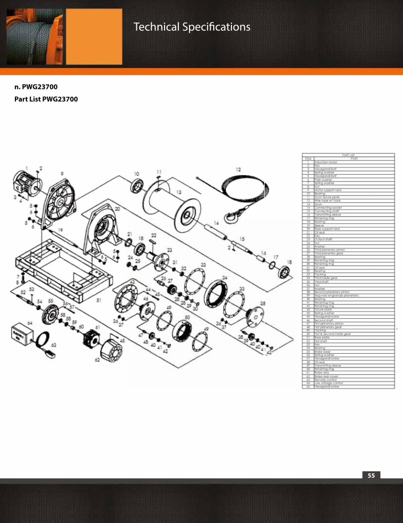
n. PWG23700
Part List PWG23700
2
DESCARGO DE RESPONSABILIDAD
Prowinch® LLC declara que ha puesto a disposición del Cliente todas y cada una de las advertencias de seguridad relativas al producto adquirido y que, en razón de ello, no asume
responsabilidad alguna por los eventuales daños o perjuicios que pudiera sufrir el cliente o terceros a causa o como consecuencia directa o indirecta del incumplimiento u omisión a alguna
de las instrucciones o advertencias de seguridad que constan en el Manual de Usuario y Advertencias de Seguridad correspondiente a la unidad adquirida.
En este sentido, Prowinch® LLC, no responderá por accidentes y/o daños a las personas y/o a la propiedad, que resultasen a consecuencia de la negligente utilización del producto.
En ningún caso Prowinch® LLC, asume ninguna responsabilidad derivada del uso de estas recomendaciones voluntarias, y no ofrece ninguna garantía en relación a ellas. Estas recomendaciones
no tienen prioridad sobre las normas vigentes de seguridad de la planta.
Para efectos de hacer valer la Garantía del producto adquirido, Prowinch® LLC, sólo responderá por eventuales desperfectos cuando sea posible acreditar que el usuario del mismo ha seguido
todas y cada una de las advertencias que constan en el Manual de Usuario y Advertencias de Seguridad.
1. Es responsabilidad exclusiva del Cliente/usuario verificar que los equipos, productos y accesorios adquiridos cumplan con las características, capacidades, elementos, componentes,
accesorios y demás condiciones para el uso que el Cliente/usuario pretende darle.
2. Es además responsabilidad exclusiva del Cliente/usuario asegurar que los equipos y productos adquiridos sean operados y mantenidos en condiciones de seguridad y por parte de personal
debidamente capacitado en el uso de los mismos, implementando además todas las medidas de seguridad que fueran necesarias para prevenir accidentes o daños a personas o bienes y
observando las indicaciones y advertencias de los manuales de uso correspondientes.
3. El eventual apoyo en la selección de los equipos, de las capacidades y características requeridas por los clientes que brinda Prowinch es entregado de forma gratuita y proporcionado en base
a la información de uso y requerimientos indicados por el Cliente mismo, información que Prowinch no puede ni le corresponde verificar. De esta forma es de todos modos responsabilidad
única y exclusiva del Cliente -o de quien hará uso de los equipos y productos adquiridos- asegurar que los mismos cumplan con las capacidades, características, mantenciones al día y todo lo
necesario para una operación correcta y segura en relación al uso que pretende darle.
4. Para Izaje de personal Prowinch recomienda el uso de winches con 4 frenos. El uso de winches de 3 o menos frenos o características de seguridad inferiores a las maximas disponibles, para
Izaje de Personal, es de exclusiva responsabilidad del cliente.
5. Con el propósito de garantizar la seguridad de los usuarios de los equipos, en especial los de Izaje de Personal, es necesario realizar las inspecciones y mantenimientos de los equipos según
la frecuencia recomendada en relación a su ciclo de trabajo, tal como está descrito por las normas ASME B30. Es obligatorio mantener registro y evidenciar los Informes escritos y fotográficos
de: Mantenimiento, Puesta en Marcha, Pruebas de Carga, Capacitaciones, Certificaciones, Inspecciones e Informes de fallas y accidentes.
6.Los informes antes mencionados deberan ser enviados mediante correo electrónico a [email protected] dentro de los primeros 7 días corridos que dicho evento haya ocurrido.
7. El cumplimiento de la realización oportuna de las actividades obligatorias descritas en los puntos 6 y 7, más todas las actividades mencionadas en las correspondientes normas aplicadas,
son de exclusiva responsabilidad del usuario. El no cumplimiento de lo anterior, desliga a Prowinch de cualquier tipo de Responsabilidad y Garantía hacia el equipo, cliente, personal y/o
usuario o cualquier otra responsabilidad que pudiese atribuirsele a Prowinch.
La información contenida en este manual puede contener errores técnicos o inexactitudes, Prowinch® LLC, no se hace responsable por errores digitación, omisión o información errada.
Este manual está sujeto a cambios sin previo aviso. Descargue la última versión disponible en www.prowinch.com
REGISTRO DE PROPIEDAD INTELECTUAL Nº 189489PROHIBIDA SU REPRODUCCIÓN TOTAL O PARCIALTODOS LOS DERECHOS RESERVADOSES PROPIEDAD DEL AUTOR ® PROWINCH 2014 - V3.6PROWINCH LLC EMPRESA CON SISTEMA DE GESTIÓN DE CALIDAD NORMA ISO 9001
3
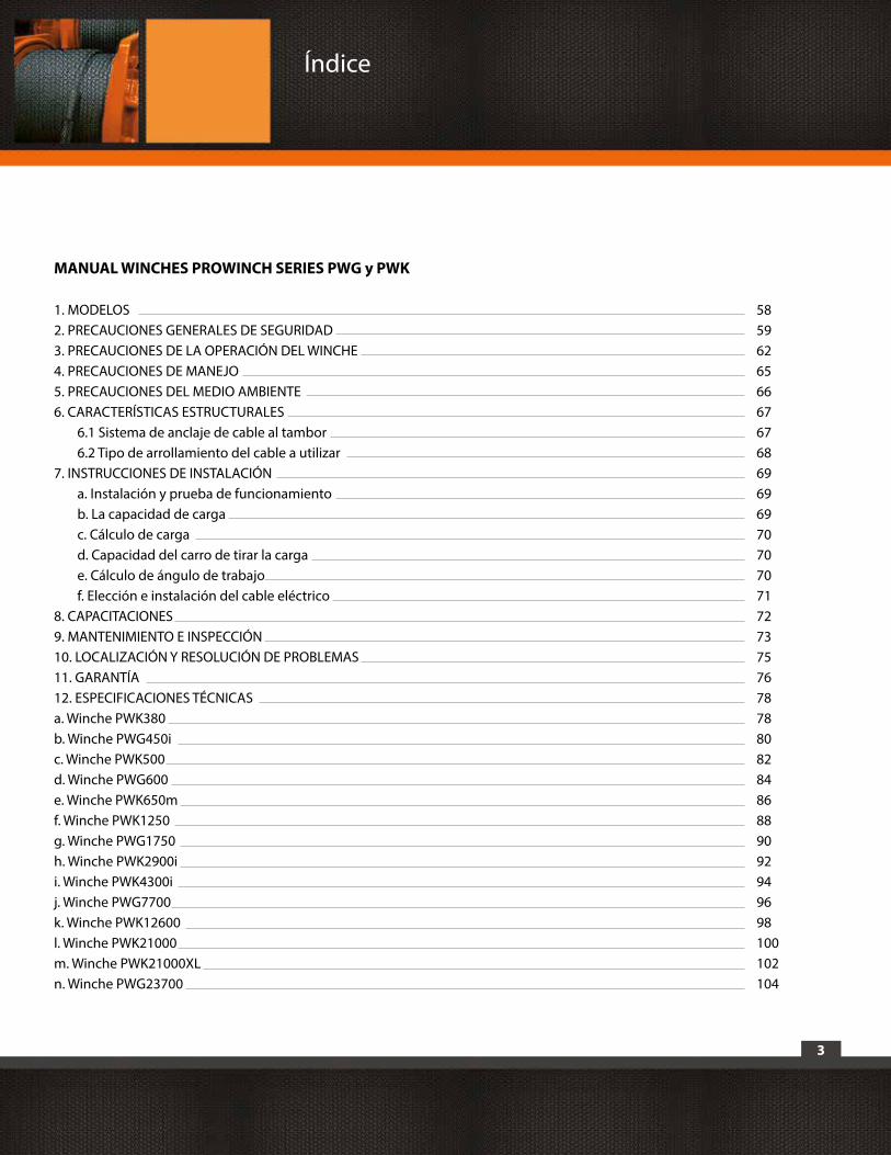
MANUAL WINCHES PROWINCH SERIES PWG y PWK
Índice
1. MODELOS 582. PRECAUCIONES GENERALES DE SEGURIDAD 593. PRECAUCIONES DE LA OPERACIÓN DEL WINCHE 624. PRECAUCIONES DE MANEJO 655. PRECAUCIONES DEL MEDIO AMBIENTE 666. CARACTERÍSTICAS ESTRUCTURALES 67 6.1 Sistema de anclaje de cable al tambor 67 6.2 Tipo de arrollamiento del cable a utilizar 687. INSTRUCCIONES DE INSTALACIÓN 69 a. Instalación y prueba de funcionamiento 69 b. La capacidad de carga 69 c. Cálculo de carga 70 d. Capacidad del carro de tirar la carga 70 e. Cálculo de ángulo de trabajo 70 f. Elección e instalación del cable eléctrico 718. CAPACITACIONES 729. MANTENIMIENTO E INSPECCIÓN 7310. LOCALIZACIÓN Y RESOLUCIÓN DE PROBLEMAS 7511. GARANTÍA 7612. ESPECIFICACIONES TÉCNICAS 78a. Winche PWK380 78b. Winche PWG450i 80c. Winche PWK500 82d. Winche PWG600 84e. Winche PWK650m 86f. Winche PWK1250 88g. Winche PWG1750 90h. Winche PWK2900i 92i. Winche PWK4300i 94j. Winche PWG7700 96k. Winche PWK12600 98l. Winche PWK21000 100m. Winche PWK21000XL 102n. Winche PWG23700 104
4
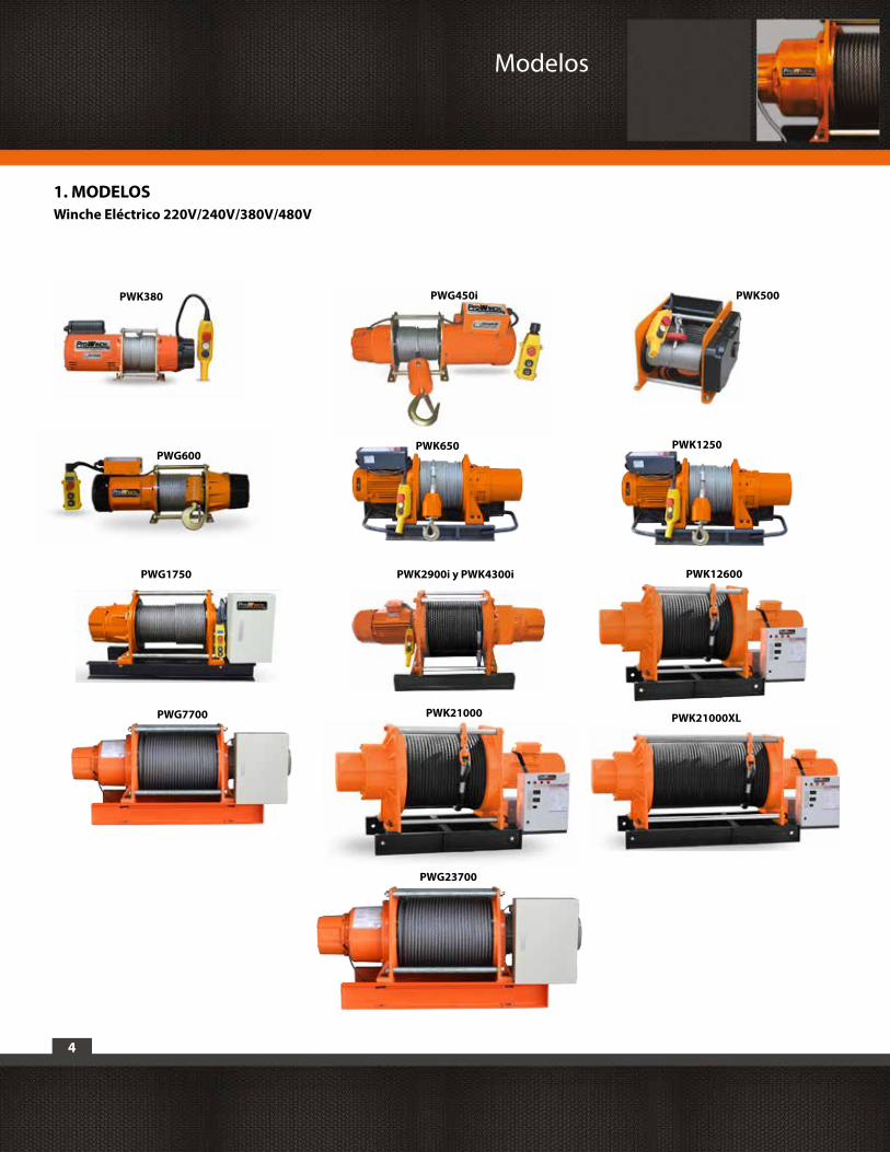
1. MODELOSWinche Eléctrico 220V/240V/380V/480V
PWG600PWK650 PWK1250
PWG1750 PWK2900i y PWK4300i
PWK380
PWG7700
PWK12600
PWG23700
PWK500
PWK21000 PWK21000XL
PWG450i
Modelos
5
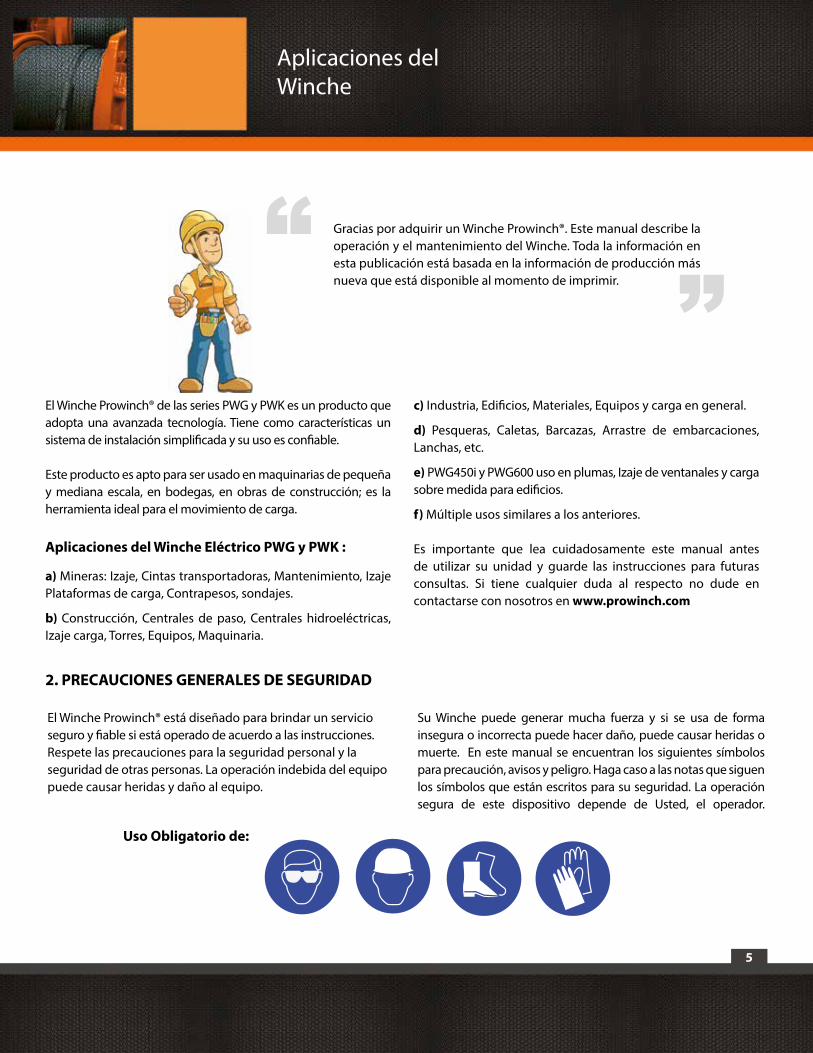
El Winche Prowinch® de las series PWG y PWK es un producto que adopta una avanzada tecnología. Tiene como características un sistema de instalación simplificada y su uso es confiable.
Este producto es apto para ser usado en maquinarias de pequeña y mediana escala, en bodegas, en obras de construcción; es la herramienta ideal para el movimiento de carga.
Aplicaciones del Winche Eléctrico PWG y PWK :
a) Mineras: Izaje, Cintas transportadoras, Mantenimiento, Izaje Plataformas de carga, Contrapesos, sondajes.
b) Construcción, Centrales de paso, Centrales hidroeléctricas, Izaje carga, Torres, Equipos, Maquinaria.
c) Industria, Edificios, Materiales, Equipos y carga en general.
d) Pesqueras, Caletas, Barcazas, Arrastre de embarcaciones, Lanchas, etc.
e) PWG450i y PWG600 uso en plumas, Izaje de ventanales y carga sobre medida para edificios.
f) Múltiple usos similares a los anteriores.
Es importante que lea cuidadosamente este manual antes de utilizar su unidad y guarde las instrucciones para futuras consultas. Si tiene cualquier duda al respecto no dude en contactarse con nosotros en www.prowinch.com
“ “Gracias por adquirir un Winche Prowinch®. Este manual describe la operación y el mantenimiento del Winche. Toda la información en esta publicación está basada en la información de producción más nueva que está disponible al momento de imprimir.
El Winche Prowinch® está diseñado para brindar un servicio seguro y fiable si está operado de acuerdo a las instrucciones. Respete las precauciones para la seguridad personal y la seguridad de otras personas. La operación indebida del equipo puede causar heridas y daño al equipo.
Su Winche puede generar mucha fuerza y si se usa de forma insegura o incorrecta puede hacer daño, puede causar heridas o muerte. En este manual se encuentran los siguientes símbolos para precaución, avisos y peligro. Haga caso a las notas que siguen los símbolos que están escritos para su seguridad. La operación segura de este dispositivo depende de Usted, el operador.
2. PRECAUCIONES GENERALES DE SEGURIDAD
Uso Obligatorio de:
Aplicaciones delWinche
6
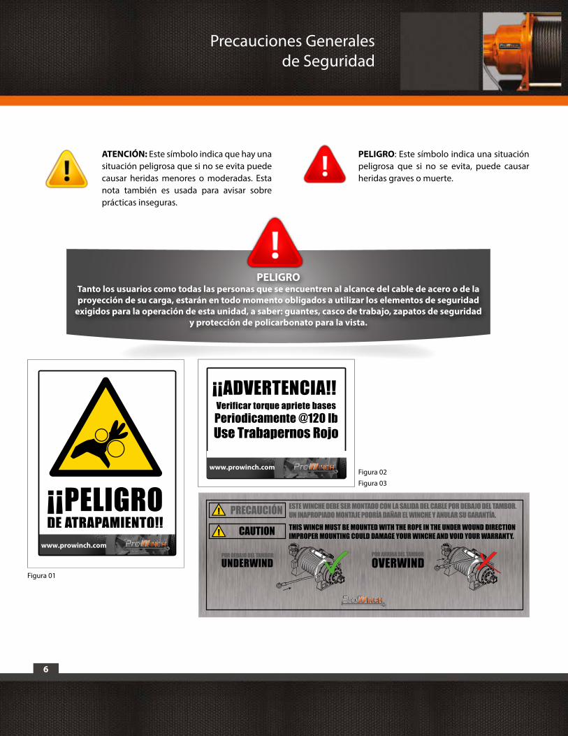
ATENCIÓN: Este símbolo indica que hay una situación peligrosa que si no se evita puede causar heridas menores o moderadas. Esta nota también es usada para avisar sobre prácticas inseguras.
PELIGRO: Este símbolo indica una situación peligrosa que si no se evita, puede causar heridas graves o muerte.
PELIGRO Tanto los usuarios como todas las personas que se encuentren al alcance del cable de acero o de la proyección de su carga, estarán en todo momento obligados a utilizar los elementos de seguridad
exigidos para la operación de esta unidad, a saber: guantes, casco de trabajo, zapatos de seguridad y protección de policarbonato para la vista.
¡¡PELIGRO DE ATRAPAMIENTO!!
www.prowinch.com
www.prowinch.com
¡¡ADVERTENCIA!! Verificar torque apriete basesPeriodicamente @120 lbUse Trabapernos Rojo
POR DEBAJO DEL TAMBORUNDERWIND
POR ARRIBA DEL TAMBOR
OVERWIND
THIS WINCH MUST BE MOUNTED WITH THE ROPE IN THE UNDER WOUND DIRECTION IMPROPER MOUNTING COULD DAMAGE YOUR WINCHE AND VOID YOUR WARRANTY.
ESTE WINCHE DEBE SER MONTADO CON LA SALIDA DEL CABLE POR DEBAJO DEL TAMBOR. UN INAPROPIADO MONTAJE PODRÍA DAÑAR EL WINCHE Y ANULAR SU GARANTÍA.
CAUTION
PRECAUCIÓN
Figura 01
Figura 02Figura 03
Precauciones Generales de Seguridad
7
2.1. Precauciones generales:
La salida del cable debe ser por la parte inferior (ver fig.03), de lo contrario el equipo puede sufrir daños debido a fuerzas de torque respecto de su base de apoyo.
- Asegúrese que el Winche cumple con las condiciones de uso.
- Mantenga el Winche en buenas condiciones y asegúrese que el cable de acero no sobresalga del tambor al enrollar.
- No use poleas ni accesorios que no estén aprobados para este Winche.
- No use cable con defectos, desgastado o con hebras rotas.
- Para reducir el riesgo de descarga eléctrica, asegúrese que el Winche está eléctricamente conectado a tierra, por personal calificado.
- Asegúrese que el Winche funciona adecuadamente en vacío, sin carga, antes de cargarlo.
- Enrolle de forma ordenada y uniforme el cable de acero en el tambor. Si el cable de acero se monta uno sobre el otro de forma cruzada es necesario que lo enrolle de nuevo.
- Desconecte el equipo de la alimentación eléctrica cuando no se use para evitar accionamientos involuntarios.
2.2. Use ropa y protección adecuada:
- No use ropas sueltas ni joyas. Se pueden enganchar en las partes que se mueven.
- Use guantes de cuero cuando toque el cable del Winche. No toque el cable con las manos desnudas ya que cables rotos pueden causar heridas.
- Debe usar zapatos de seguridad antideslizantes y casco de seguridad.
- Use algún tipo de protección para contener pelo largo.
- Siempre use gafas protectoras. Use algo para proteger toda la cara si está sacando astillas de madera o de metal. Use una mascarilla de respiración para el polvo cuando hay metal, madera y polvo de químicos.
2.3. Mantenga una distancia segura:
- Asegúrese que todas las personas estén lejos del cable del Winche y la carga, cuando el Winche está en operación. Es recomendable que esa distancia sea 1,5 veces la longitud del cable. Si el cable se suelta o se rompe por la carga, puede azotar y causar daño personal grave o muerte.
- No pase por encima del cable.
- Es necesario asegurar que todos los visitantes y espectadores se queden lejos del área de trabajo.
- Mantenga equilibrio todo el tiempo.
2.4. No abuse del cable eléctrico:
- Nunca levante el Winche por el cable eléctrico ni tire para desconectarlo.
- Aleje el cable del calor, aceite y bordes afilados.
- Nunca saque todo el cable, mantenga al menos 5 vueltas en el tambor.
2.5. No haga que el Winche trabaje demasiado:
- Si el motor se pone muy caliente, deténgalo y deje que se enfríe por algunos minutos.
- Si el Winche se detiene en la operación, detenga la operación y revise la carga y el carro.
- No exceda la capacidad máxima mostrada en la tabla (tabla página 17). Las cargas no deben exceder esas medidas.
2.6. Revise las partes dañadas:- Antes de usar, es necesario revisar el Winche completamente. Es necesario que un centro de servicio autorizado repare o sustituya cualquier parte que está dañada.
Precauciones Generales de Seguridad
8
2.7. Repare el Winche:-Para reparar use sólo repuestos originales Prowinch®, en caso contrario puede poner el usuario en peligro. El uso de cualquier otro repuesto hará que la garantía caduque y quede sin efecto. Sólo use accesorios fabricados para este Winche.
2.8. Enrollar el cable:
- Debe llevar guantes de cuero para enrollar el cable. Para enrollar correctamente es necesario mantener una carga pequeña en el cable. Mientras el operador enrolla el cable otra persona debe guiarlo en su correcta ubicación. Empiece lo más lejos y lo más al centro que pueda. Camine con la carga en el cable mientras el Winche enrolla.
- No permita que el cable se caiga y no se acerque al Winche.
- Apague el Winche y repita el proceso hasta que sólo quede 1 metro de cable.
- Desconecte el control remoto y/o corte el suministro eléctrico.
- Es necesario que el final del cable quede enrollado por lo menos 5 vueltas en el tambor para soportar la carga.
- Cuando se utilicen cables IWRC de alambres de acero, use guantes para eliminar la posibilidad de cortes causados por hebras rotas. Inspeccione el cable y el equipamiento frecuentemente. El cable deberá ser reemplazado inmediatamente si hay signos de desgaste, torceduras, oxidación, hebras rotas o cualquier otra señal de deterioro.
Prowinch LLC y sus distribuidores capacitan y otorgan Certificados de Capacitación en el USO y MANTENIMIENTO de toda la línea de productos.
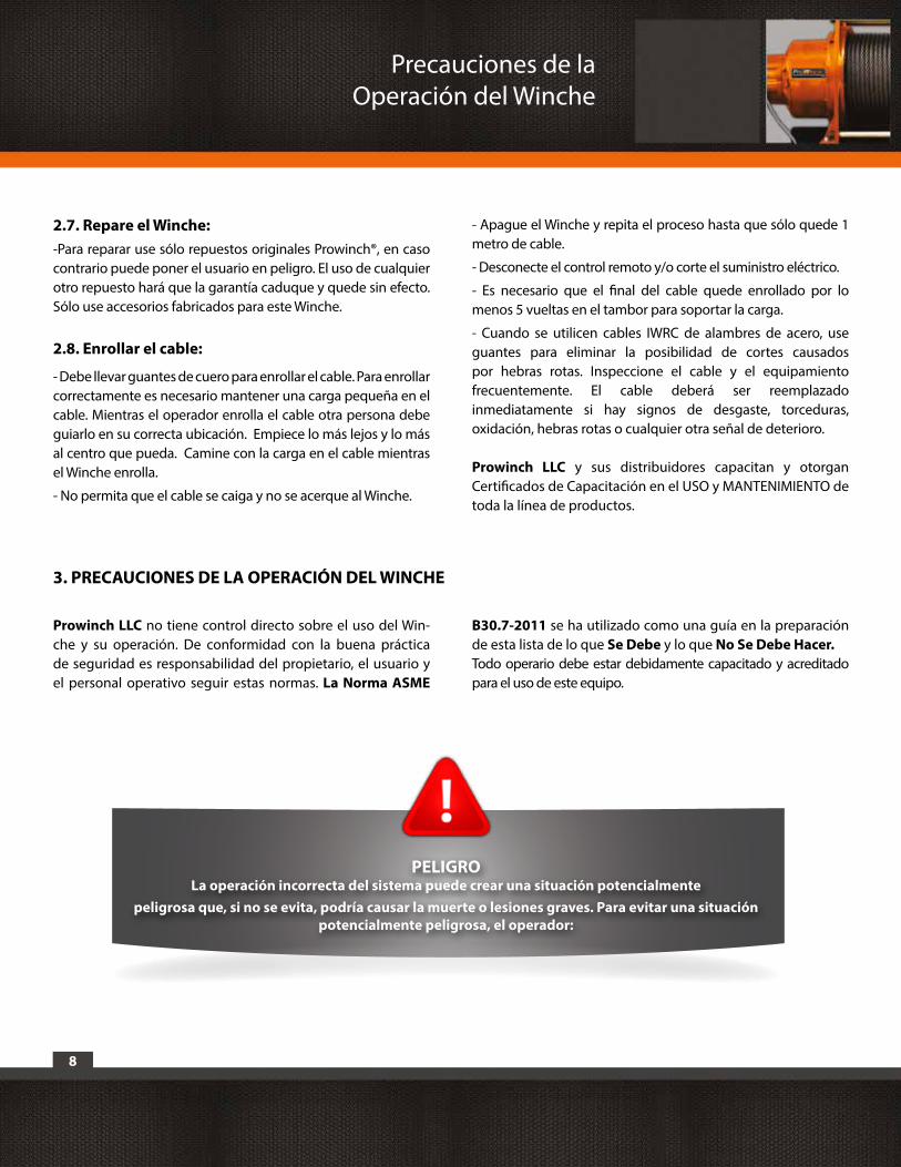
PELIGRO La operación incorrecta del sistema puede crear una situación potencialmente
peligrosa que, si no se evita, podría causar la muerte o lesiones graves. Para evitar una situación potencialmente peligrosa, el operador:
Prowinch LLC no tiene control directo sobre el uso del Win-che y su operación. De conformidad con la buena práctica de seguridad es responsabilidad del propietario, el usuario y el personal operativo seguir estas normas. La Norma ASME
B30.7-2011 se ha utilizado como una guía en la preparación de esta lista de lo que Se Debe y lo que No Se Debe Hacer.Todo operario debe estar debidamente capacitado y acreditado para el uso de este equipo.
3. PRECAUCIONES DE LA OPERACIÓN DEL WINCHE
Precauciones de la Operación del Winche
9
1. No operará el winche hasta que haya leído y entendido completamente estas normas y el manual del equipo entregado por Prowinch, incluidas las instrucciones y manuales de mantenimiento.
2. No operará un winche dañado, que funcione de forma incorrecta o intermitente.
3. No operará un equipo que ha sido modificado sin la probación del fabricante.
4. No alzará más de la carga nominal descrita para el equipo.
5. No podrá utilizar montacargas o grúa dañadas que no estén funcionando correctamente.
6. No podrá utilizar el winche con daños en el cable: torceduras, dobladuras, oxidación, hebras rotas o desgastadas.
7. No usará ningún tipo de extensión o modificación al winche.
8. No liberará la carga mientras el sistema esté con peso.
9. No podrá utilizar el winche para levantar personas a excepción de aquellos equipos que cumplan con la norma ASME B30.7-2011 en instalaciones que cumplan con la norma ASME B30.23-2005 o que estén aprobados por SERNAGEOMIN. La responsabilidad de estas maniobras y el cumplimiento de estas normas son de las empresas y personas que las realizan.
10. No alzará cargas sobre las personas y se asegurará que todo el personal permanezca distante de la carga soportada.
11. No tratará de alargar o reparar el cable.
12. Protegerá el cable de carga de salpicaduras de soldadura u otros contaminantes dañinos.
13. No debe operar el winche si hay cualquier objeto o elemento que roce o desvíe inadecuadamente el cable.
14. No aplicará la carga a la punta del gancho o al cerrojo del gancho.
15. No usará el equipo con un accesorio, polea, eslinga, grillete o elemento adicional que no se encuentre en optimas condiciones y cumpla con las especificaciones de carga requeridas para la maniobra.
16. No debe operar más allá de los límites de recorrido.
17. No podrá abandonar la carga siendo esta soportada por el winche sin que se adopten precauciones concretas.
18. No permitirá el uso del cable o gancho como una tierra eléctrica y/o soldadura.
19. No permitirá que el cable o gancho sean tocados por un electrodo de soldadura en vivo.
20. No deberá retirar u ocultar estas advertencias.
21. No deberá operar un winche que no haya sido instalado y anclado cumpliendo con los cálculos y normas correspondientes.
22. No alzará cargas que no están en equilibrio y que la acción de contención no es segura, manteniendo la holgura correspondiente.
23. No deberá operar un winche a menos que todas las personas presentes estén distantes de la carga, el cable y su proyección.
24. Informará sobre un mal funcionamiento o actuaciones de elevación inusual.
25. No deberá operar un winche en el que las placas de seguridad o adhesivos no se encuentran o son ilegibles.
26. No operará el equipo sin los elementos de seguridad: Zapatos de Seguridad, Guantes adecuados, Casco de Seguridad, Protección de policarbonato para la vista y cualquier otro elemento adicional requerido en la obra.
27. Desconectará el winche del suministro eléctrico si el equipo es desatendido.
28. La Conexión eléctrica debe contar con un automático ó guarda motor que permita desenergizar el equipo. Este debe estar al alcance del operario.
29. No operar el winche sin las protecciones de motor y partes móviles.
Precauciones de la Operación del Winche
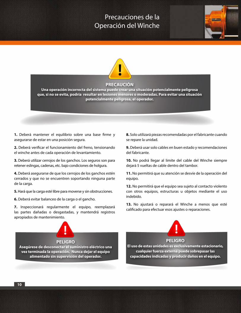
10
1. Deberá mantener el equilibrio sobre una base firme y asegurarse de estar en una posición segura.
2. Deberá verificar el funcionamiento del freno, tensionando el winche antes de cada operación de levantamiento.
3. Deberá utilizar cerrojos de los ganchos. Los seguros son para retener eslingas, cadenas, etc. bajo condiciones de holgura.
4. Deberá asegurarse de que los cerrojos de los ganchos estén cerrados y que no se encuentren soportando ninguna parte de la carga.
5. Hará que la carga esté libre para moverse y sin obstrucciones.
6. Deberá evitar balanceo de la carga o el gancho.
7. Inspeccionará regularmente el equipo, reemplazará las partes dañadas o desgastadas, y mantendrá registros apropiados de mantenimiento.
8. Solo utilizará piezas recomendadas por el fabricante cuando se repare la unidad.
9. Deberá usar solo cables en buen estado y recomendaciones del fabricante.
10. No podrá llegar al limite del cable del Winche siempre dejará 5 vueltas de cable dentro del tambor.
11. No permitirá que su atención se desvíe de la operación del equipo.
12. No permitirá que el equipo sea sujeto al contacto violento con otros equipos, estructuras u objetos mediante el uso indebido.
13. No ajustará o reparará el Winche a menos que esté calificado para efectuar esos ajustes o reparaciones.
PRECAUCIÓN Una operación incorrecta del sistema puede crear una situación potencialmente peligrosa
que, si no se evita, podría resultar en lesiones menores o moderadas. Para evitar una situación potencialmente peligrosa, el operador.
PELIGRO Asegúrese de desconectar el suministro eléctrico una
vez terminada la operación. Nunca dejar el equipo alimentado sin supervisión del operador.
PELIGRO El uso de estas unidades es exclusivamente estacionario,
cualquier fuerza externa puede sobrepasar las capacidades indicadas y producir daños en el equipo.
Precauciones de la Operación del Winche
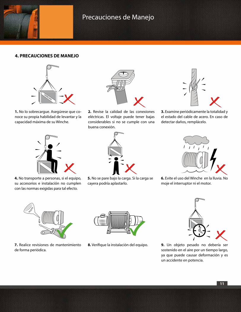
11
5. No se pare bajo la carga. Si la carga se cayera podría aplastarlo.
4. PRECAUCIONES DE MANEJO
1. No lo sobrecargue. Asegúrese que co-noce su propia habilidad de levantar y la capacidad máxima de su Winche.
4. No transporte a personas, si el equipo, su accesorios e instalación no cumplen con las normas exigidas para tal efecto.
7. Realice revisiones de mantenimiento de forma periódica.
8. Verifique la instalación del equipo.
6. Evite el uso del Winche en la lluvia. No moje el interruptor ni el motor.
2. Revise la calidad de las conexiones eléctricas. El voltaje puede tener bajas considerables si no se cumple con una buena conexión.
3. Examine periódicamente la totalidad y el estado del cable de acero. En caso de detectar daños, remplácelo.
OVERLOAD
9. Un objeto pesado no debería ser sostenido en el aire por un tiempo largo, ya que puede causar deformación y es un accidente en potencia.
Precauciones de Manejo
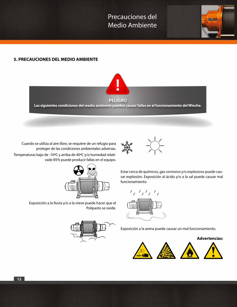
12
Exposición a la lluvia y/o a la nieve puede hacer que el Polipasto se oxide.
Cuando se utiliza al aire libre, se requiere de un refugio para proteger de las condiciones ambientales adversas.
Temperaturas bajo de -10ºC y arriba de 40ºC y/o humedad relati-vade 85% puede producir fallas en el equipo.
Estar cerca de químicos, gas corrosivo y/o explosivos puede cau-sar explosión. Exposición al ácido y/o a la sal puede causar mal funcionamiento.
Exposición a la arena puede causar un mal funcionamiento.
Advertencias:
PELIGRO Las siguientes condiciones del medio ambiente pueden causar fallas en el funcionamiento del Winche.
5. PRECAUCIONES DEL MEDIO AMBIENTE
Precauciones del Medio Ambiente
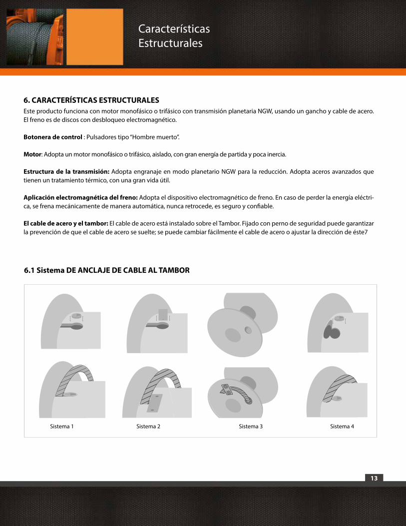
13
6. CARACTERÍSTICAS ESTRUCTURALESEste producto funciona con motor monofásico o trifásico con transmisión planetaria NGW, usando un gancho y cable de acero. El freno es de discos con desbloqueo electromagnético.
Botonera de control : Pulsadores tipo “Hombre muerto”.
Motor: Adopta un motor monofásico o trifásico, aislado, con gran energía de partida y poca inercia.
Estructura de la transmisión: Adopta engranaje en modo planetario NGW para la reducción. Adopta aceros avanzados que tienen un tratamiento térmico, con una gran vida útil.
Aplicación electromagnética del freno: Adopta el dispositivo electromagnético de freno. En caso de perder la energía eléctri-ca, se frena mecánicamente de manera automática, nunca retrocede, es seguro y confiable.
El cable de acero y el tambor: El cable de acero está instalado sobre el Tambor. Fijado con perno de seguridad puede garantizar la prevención de que el cable de acero se suelte; se puede cambiar fácilmente el cable de acero o ajustar la dirección de éste7
CaracterísticasEstructurales
6.1 Sistema DE ANCLAJE DE CABLE AL TAMBOR
Anclaje1 Anclaje2 Anclaje 3 Anclaje 4Sistema 1 Sistema 3Sistema 2 Sistema 4
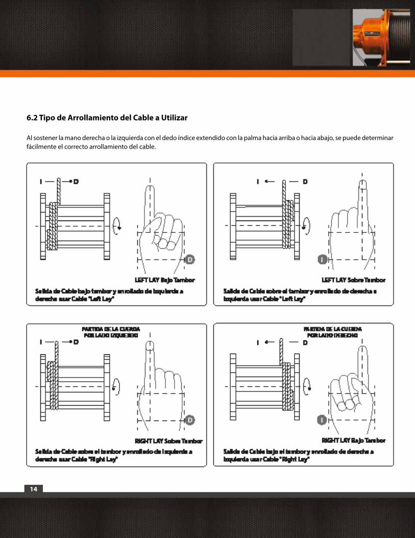
14
6.2 Tipo de Arrollamiento del Cable a Utilizar
Al sostener la mano derecha o la izquierda con el dedo índice extendido con la palma hacia arriba o hacia abajo, se puede determinar fácilmente el correcto arrollamiento del cable.
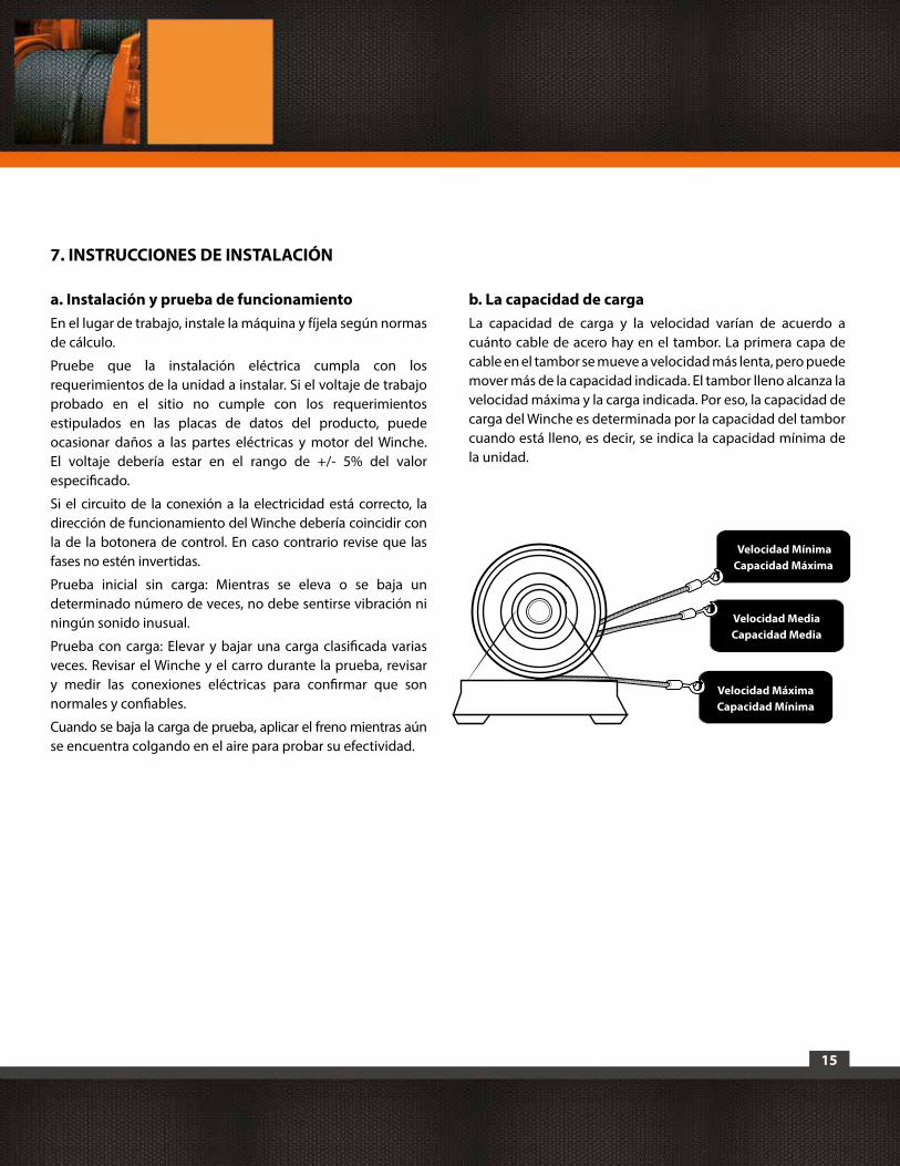
15
a. Instalación y prueba de funcionamientoEn el lugar de trabajo, instale la máquina y fíjela según normas de cálculo.
Pruebe que la instalación eléctrica cumpla con los requerimientos de la unidad a instalar. Si el voltaje de trabajo probado en el sitio no cumple con los requerimientos estipulados en las placas de datos del producto, puede ocasionar daños a las partes eléctricas y motor del Winche. El voltaje debería estar en el rango de +/- 5% del valor especificado.
Si el circuito de la conexión a la electricidad está correcto, la dirección de funcionamiento del Winche debería coincidir con la de la botonera de control. En caso contrario revise que las fases no estén invertidas.
Prueba inicial sin carga: Mientras se eleva o se baja un determinado número de veces, no debe sentirse vibración ni ningún sonido inusual.
Prueba con carga: Elevar y bajar una carga clasificada varias veces. Revisar el Winche y el carro durante la prueba, revisar y medir las conexiones eléctricas para confirmar que son normales y confiables.
Cuando se baja la carga de prueba, aplicar el freno mientras aún se encuentra colgando en el aire para probar su efectividad.
b. La capacidad de cargaLa capacidad de carga y la velocidad varían de acuerdo a cuánto cable de acero hay en el tambor. La primera capa de cable en el tambor se mueve a velocidad más lenta, pero puede mover más de la capacidad indicada. El tambor lleno alcanza la velocidad máxima y la carga indicada. Por eso, la capacidad de carga del Winche es determinada por la capacidad del tambor cuando está lleno, es decir, se indica la capacidad mínima de la unidad.
7. INSTRUCCIONES DE INSTALACIÓN
Velocidad MáximaCapacidad Mínima
Velocidad MediaCapacidad Media
Velocidad MínimaCapacidad Máxima
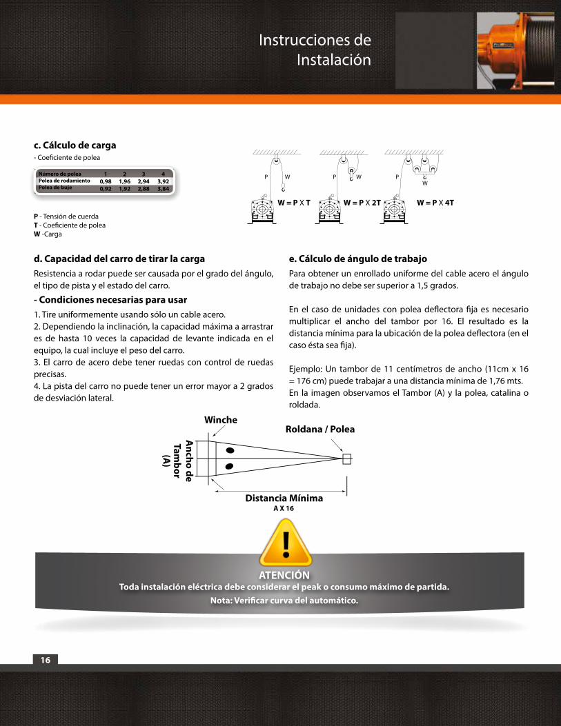
16
d. Capacidad del carro de tirar la cargaResistencia a rodar puede ser causada por el grado del ángulo, el tipo de pista y el estado del carro.
- Condiciones necesarias para usar1. Tire uniformemente usando sólo un cable acero.2. Dependiendo la inclinación, la capacidad máxima a arrastrar es de hasta 10 veces la capacidad de levante indicada en el equipo, la cual incluye el peso del carro.3. El carro de acero debe tener ruedas con control de ruedas precisas. 4. La pista del carro no puede tener un error mayor a 2 grados de desviación lateral.
e. Cálculo de ángulo de trabajo Para obtener un enrollado uniforme del cable acero el ángulo de trabajo no debe ser superior a 1,5 grados.
En el caso de unidades con polea deflectora fija es necesario multiplicar el ancho del tambor por 16. El resultado es la distancia mínima para la ubicación de la polea deflectora (en el caso ésta sea fija).
Ejemplo: Un tambor de 11 centímetros de ancho (11cm x 16 = 176 cm) puede trabajar a una distancia mínima de 1,76 mts.En la imagen observamos el Tambor (A) y la polea, catalina o roldada.
c. Cálculo de carga- Coeficiente de polea
Número de poleaPolea de rodamiento Polea de buje
43,923,84
21,961,92
10,980,92
32,942,88
P - Tensión de cuerdaT - Coeficiente de poleaW -Carga
A X 16
Roldana / PoleaWinche
Distancia Mínima
Ancho de
Tambor
(A)
W = P X T
P P PW WW
W = P X 2T W = P X 4T
ATENCIÓNToda instalación eléctrica debe considerar el peak o consumo máximo de partida.
Nota: Verificar curva del automático.
Instrucciones de Instalación

17
f. Elección e instalación del cable eléctrico.1. La especificación del cable afecta a la vida útil y el rendimiento del Winche eléctrico y la vida útil del motor. Es muy importante leer los contenidos en la lista del siguiente formulario cuidadosamente antes de usarlo. No se puede usar un cable de electricidad que sea menor a los que aparecen en la lista de la especificación, a continuación.
2. El largo del cable alimentador, en la lista ubicada en el formulario, no puede exceder los 50 metros. El cable alimentador debería ser engrosado si esta medida fuera excedida, para evitar una caída de tensión.
3. Cuando se utilice en una construcción, se debe usar conductor eléctrico cuya alma conductora está formada por una serie de hilos conductores o alambres de baja sección, lo que otorga una gran flexibilidad y mayor seguridad.
4. Cuando el cable sea conectado a la electricidad, debe hacerse directo al interruptor maestro y sujeto firmemente en su lugar usando un perno.
5. Cada conexión de la línea del cable debe estar asegurada en su lugar mediante el uso de un perno; si se soltase, los contactos se conectarían de manera incorrecta, produciendo chispas o altas temperaturas, etc. Esto influiría en la vida útil de la máquina.
6. La línea del cable debe ser fijada desde un extremo. Al fijarla, el cable debe estar conectado firmemente; si uno o más se soltasen, entonces el voltaje bajaría, lo que influenciaría seriamente sobre el rendimiento de la máquina.
7. Para garantizar la seguridad de las personas el cable verde debe hacer contacto “a tierra”. Su línea alimentadora debe instalarse dentro de un interruptor adicional para evitar fugas.
ATENCIÓNEl cliente asume la responsabilidad de hacer instalar su unidad por personas calificadas y que cumplan con
las normas exigidas en este manual. Todo cálculo estructural debe ser hecho por un Ingeniero Calculista debidamente acreditado y que certifique la instalación. Una instalación no adecuada puede producir graves accidentes a los usuarios y personas cercanas al lugar de operación de la unidad. Una instalación deficiente o
incorrecta hará caducar inmediatamente la garantía de la unidad, al igual que en el caso de realizar una conexión eléctrica que no cumpla con las especificaciones descritas en el Manual de cada unidad o las normas generales para su consumo. Cualquier tipo de intervención en la unidad por personas o empresas ajenas a Prowinch hará
caducar inmediatamente la garantía de la misma.
Trifásico 380V/480VDiametro del Cable (mm²)
1100W2.5
2200W2.5
3000W4
4000W4
5500W5.5
7500W8
Instrucciones de Instalación
18
Prowinch con el propósito de contribuir con la protección y la integridad física de todos los usuarios, trabajadores, empleados, empleadores, propietarios y de todas las personas relacionadas con la operación y uso de los Winches, realiza capacitaciones para el uso y mantenimiento de Winches aplicados a distintos tipos de trabajos. Esto en el entendido de que la seguridad no tiene que ver solamente con un producto en particular, sino que además con toda la cadena de procesos involucrados en la instalación, operación, mantención y utilización de los mencionados equipos.
Para este propósito hemos desarrollado Manuales Instructivos aplicados al Uso y Mantenimiento de los Winches e Izaje de Plataformas de Personal, los cuales contienen importantes referencias e indicaciones que es preciso conocer, considerar u observar para realizar una segura y correcta utilización de los Winches, para que en conjunto a sus componentes y accesorios puedan cumplir de forma segura con el ciclo de vida y trabajo esperado. Estos manuales han sido desarrollados teniendo en
cuenta la experiencia adquirida y basándose en las principales indicaciones que emanan de las Normas ASME B30.7 Winches y ASME B30.23 Sistemas de Izaje para Personal.
Cabe señalar que Prowinch ha adquirido los derechos y recibido las correspondientes autorizaciones y licencias por parte de la American Society of Mechanical Engineers ASME para traducir y reproducir estas normas, con el consentimiento escrito del Departamento de códigos y Estándar de la misma ASME, para así aplicarlas en nuestros manuales instructivos en un determinado número de copias controladas y con los derechos de autor correspondientes. Le invitamos a conocernos y con gusto le daremos nuestro asesoramiento.
8. CAPACITACIONES
Capacitaciones
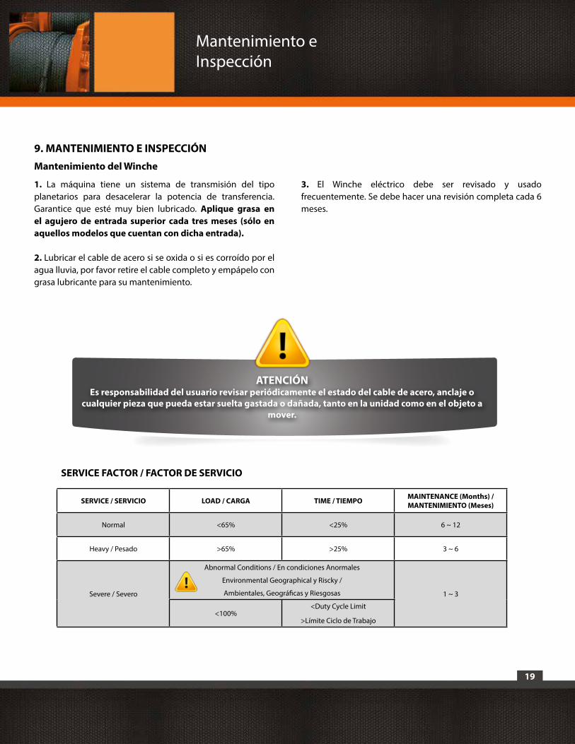
19
9. MANTENIMIENTO E INSPECCIÓN
Mantenimiento del Winche
1. La máquina tiene un sistema de transmisión del tipo planetarios para desacelerar la potencia de transferencia. Garantice que esté muy bien lubricado. Aplique grasa en el agujero de entrada superior cada tres meses (sólo en aquellos modelos que cuentan con dicha entrada).
2. Lubricar el cable de acero si se oxida o si es corroído por el agua lluvia, por favor retire el cable completo y empápelo con grasa lubricante para su mantenimiento.
3. El Winche eléctrico debe ser revisado y usado frecuentemente. Se debe hacer una revisión completa cada 6 meses.
ATENCIÓNEs responsabilidad del usuario revisar periódicamente el estado del cable de acero, anclaje o
cualquier pieza que pueda estar suelta gastada o dañada, tanto en la unidad como en el objeto a mover.
Mantenimiento e Inspección
SERVICE / SERVICIO LOAD / CARGA TIME / TIEMPO MAINTENANCE (Months) / MANTENIMIENTO (Meses)
Normal <65% <25% 6 ~ 12
Heavy / Pesado >65% >25% 3 ~ 6
Severe / Severo
Abnormal Conditions / En condiciones Anormales
Environmental Geographical y Riscky /
Ambientales, Geográficas y Riesgosas 1 ~ 3
<100%<Duty Cycle Limit
>Límite Ciclo de Trabajo
SERVICE FACTOR / FACTOR DE SERVICIO
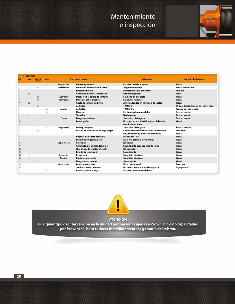
20
ATENCIÓN Cualquier tipo de intervención en la unidad por personas ajenas a Prowinch® o no capacitadas
por Prowinch®, hará caducar inmediatamente la garantía del mismo.
Día Mes
FrecuenciaParte para revisar Referencia Método de RevisiónCada 3
mesesAño
Etiqueta y marcasEnrollado y dirección del cableFuncionamientoCondición de cables eléctricosDesgaste del punto de contactoDaño del cable eléctricoCable de conexión a tierraAislaciónAislaciónManchasTornillosDesgaste de discosDesempeño
Daño y desgasteEstado de lubricación de engranajes
Ruptura de hebras del cableDisminución del diámetroCorrosiónCondición del anclaje del cableQue se puede enrollar el cableEstado de lubricaciónEstructuraRuptura de pestañaDesgaste del tamborDirección rotativoSonido rotativo anormalPrueba de sobrecarga
VisualVisual y medición ManualVisualVisualVisualVisual500v aislación Prueba de resistencia Prueba de resistencia Revisar averíasRevisar averíasRevisar averíasVisual
Revisar averíasMediciónVisualVisualVisualVisualVisualVisualVisualVisualVisualVisualEscucharBajo prueba
x
x
x
x
xx
x
xx
x
x
x
x
Etiquetado Instalación
Control/ Interruptor
Motor
Freno
Engranaje
Cable Acero
ArmazónTambor
Operación
Existencia de la etiquetaÁngulo de trabajoFuncionamiento adecuadoDaños y sujeciónSin daño de desgasteSin cortes ni dañosAnormalidades en conexión de cables1 MQ min1 MQ min.Existencia de anormalidadNada sueltoSin daños ni desgasteNo superior a 1,5% de longitud del cable enrollada en 1 minSin daños ni desgasteLa suficiente cantidad de lubricante Mobilux EP2,Shell Unedo 2 o Esso Beacon EP2Menos del 10%Máx. 7% del diámetro normalNo severaLa suficiente para soportar la cargaNo irregularLa suficienteSin grieta ni roturaSin grieta ni roturaSin desgasteDirección normalNo oscilación ni sonido de impactoExistencia de anormalidades
x
x
x
xxxxxxxx
xx
x
xx
x
x
Mantenimientoe inspección
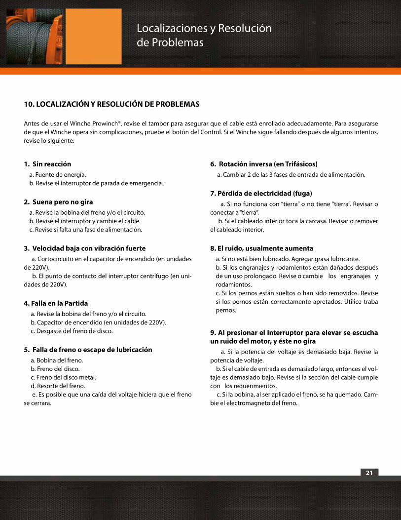
21
1. Sin reaccióna. Fuente de energía.b. Revise el interruptor de parada de emergencia.
2. Suena pero no giraa. Revise la bobina del freno y/o el circuito. b. Revise el interruptor y cambie el cable.c. Revise si falta una fase de alimentación.
3. Velocidad baja con vibración fuerte a. Cortocircuito en el capacitor de encendido (en unidades de 220V). b. El punto de contacto del interruptor centrífugo (en uni-dades de 220V).
4. Falla en la Partida a. Revise la bobina del freno y/o el circuito. b. Capacitor de encendido (en unidades de 220V). c. Desgaste del freno de disco.
5. Falla de freno o escape de lubricación a. Bobina del freno. b. Freno del disco. c. Freno del disco metal. d. Resorte del freno. e. Es posible que una caída del voltaje hiciera que el freno se cerrara.
6. Rotación inversa (en Trifásicos) a. Cambiar 2 de las 3 fases de entrada de alimentación.
7. Pérdida de electricidad (fuga) a. Si no funciona con “tierra” o no tiene “tierra”. Revisar o conectar a “tierra”. b. Si el cableado interior toca la carcasa. Revisar o remover el cableado interior.
8. El ruido, usualmente aumentaa. Si no está bien lubricado. Agregar grasa lubricante.b. Si los engranajes y rodamientos están dañados después de un uso prolongado. Revise o cambie los engranajes y rodamientos.c. Si los pernos están sueltos o han sido removidos. Revise si los pernos están correctamente apretados. Utilice traba pernos.
9. Al presionar el Interruptor para elevar se escucha un ruido del motor, y éste no gira a. Si la potencia del voltaje es demasiado baja. Revise la potencia de voltaje. b. Si el cable de entrada es demasiado largo, entonces el vol-taje es demasiado bajo. Revise si la sección del cable cumple con los requerimientos. c. Si la bobina, al ser aplicado el freno, se ha quemado. Cam-bie el electromagneto del freno.
10. LOCALIZACIÓN Y RESOLUCIÓN DE PROBLEMAS
Antes de usar el Winche Prowinch®, revise el tambor para asegurar que el cable está enrollado adecuadamente. Para asegurarse de que el Winche opera sin complicaciones, pruebe el botón del Control. Si el Winche sigue fallando después de algunos intentos, revise lo siguiente:
Localizaciones y Resolución de Problemas
22
1) Toda Garantía solo es válida con su respectiva Boleta o Factura por el periodo de 1 año a contar de la fecha de su emisión.
2) Unidades tipo Equipos de Levante de Carga Estacionarios y con Carro 220V~500V, si bien son diseñadas para levantar carga, queda terminantemente prohibido su uso para levantar Personas u objetos/carga sobre ellas. Toda persona debe mantenerse lejos de la proyección del cable, gancho y la carga.
3) Es responsabilidad de cada usuario el hacer instalar su unidad por personas calificadas y que cumplan con las normas exigidas en el manual de cada unidad y en estas indicaciones. Todo cálculo estructural debe ser hecho por un Ingeniero Calculista debidamente acreditado y que certifique la instalación. Una instalación no adecuada puede producir graves accidentes a los usuarios y a personas cercanas al lugar de operación de la unidad. Una Instalación no adecuada caduca inmediatamente la garantía de la unidad.
4) Es responsabilidad de cada usuario operar el equipo por personal debidamente calificado según las normas ASME B30 correspondientes. Como también mantener y realizar las pautas de mantenimiento y revisiones descritas dentro de la misma norma. Prowinch realiza capacitaciones y certifica operadores.
5) En el caso de realizar una conexión eléctrica que no cumpla con las especificaciones descritas en el manual de cada unidad o las normas generales para su consumo, caducará inmediatamente la garantía. 6) Es responsabilidad del usuario revisar periódicamente el estado del cable de acero, anclajes o cualquier pieza que pueda estar suelta, gastada o dañada, tanto en la unidad como en el objeto a remolcar o levantar.
7) El usuario es responsable de usar los elementos de seguridad exigidos para la operación de estas unidades: Guantes de cuero gruesos, casco de trabajo, zapatos de seguridad y protección de policarbonato para la vista. Además tiene que velar que todas las personas cercanas, estén usando estos mismos elementos de seguridad.
8) Cualquier tipo de intervención en la unidad por personas o empresas ajenas a Prowinch es causal de caducamiento inmediato de la garantía de la unidad.
9) Todo equipo Prowinch tiene sellos de garantía en su parte motriz y reductora, la carencia o ruptura de estos sellos es motivo de caducamiento inmediato de la garantía.
10) La instalación de Winches en bases no adecuadamente alineadas y sin las perforaciones exactas de anclaje caduca inmediatamente la garantía.
11) Es de responsabilidad del usuario alimentar los equipos con corriente estabilizada, con el voltaje y ciclaje que corresponda para cada unidad.
12) La garantía Prowinch cubre solo defectos de fabricación.
11. GARANTÍA
Garantía
23
13) Toda unidad que presente signos de abuso, uso severo por sobre sus capacidades indicadas y/o, presente Bobinas, Estatores, Rotores, o circuitos quemados no son cubiertos por la garantía.
14) Es responsabilidad del usuario no sobrepasar las cargas indicadas de cada unidad, si usted tiene cualquier duda en la instalación, uso o funcionamiento de su unidad y/o requiera de capacitaciones, solicite asistencia técnica en www.prowinch.com.
15) Toda garantía es dada en nuestras instalaciones. Los repuestos enviados por garantía a otras ciudades o países no incluyen los costos de envío, teniendo estos que ser cubiertos por el cliente.
16) La garantía no cubre costos de traslado de los equipos, desmontaje, traslado de personal, lucro cesante, faenas detenidas o cualquier otro costo que se pudiese relacionar al cese de funcionamiento de un equipo.
17) En el caso se solicite visita técnica a terreno, está siempre será cancelada por parte del cliente, independiente de que en ella se hagan servicios sin costo cubiertos por la garantía. Se entiende como visita técnica a terreno a los costos involucrados por el traslado del personal, transporte, combustible, alimentación, alojamiento, horas extras, etc.
18) La garantía solo es válida al comprador directo no extendiéndose si este vende, traspasa o transfiere el producto a terceros.
19) Exclusiones de la garantía: -Si la avería es producida por agentes meteorológicos.-Si la avería es producida por agentes externos como: fuego, agua, golpes, aplastamiento o aplicación de voltaje o energía inadecuada. -Las averías producidas por rotura física, tales como carcasa, plásticos, pinturas, esmaltes, cristales, embellecedores, similares.-Productos que presenten daño causado por transporte inadecuado, vandalismo, arena, desastres naturales como terremotos, inundaciones, incendios, etc.
20) Vencimiento de Garantías: Incluida: 1 Año a contar de la fecha de compra indicada en la Boleta o Factura.Contratada: 2 Años, Garantía extra contratada por el cliente al momento de la compra del producto.
Garantía

24
Especificaciones Técnicas
12. ESPECIFICACIONES TÉCNICAS
a. Winche PWK380
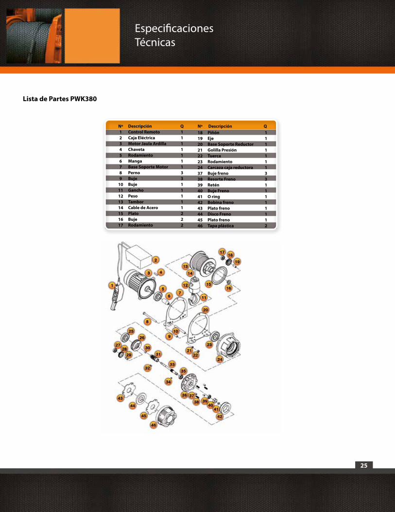
25
Lista de Partes PWK380
DescripciónControl RemotoCaja EléctricaMotor Jaula ArdillaChavetaRodamientoMangaBase Soporte MotorPernoBujeBujeGanchoPesoTamborCable de AceroPlatoBujeRodamiento
PiñónEjeBase Soporte ReductorGolilla PresiónTuercaRodamientoCarcaza caja reductoraBuje frenoResorte FrenoReténBuje FrenoO ringBobina frenoPlato frenoDisco FrenoPlato frenoTapa plástica
Q11111113311111222
11111113311111112
Nº Descripción QNº123456789
1011121314151617
1819202122232437383940414243444546
Especificaciones Técnicas

26
b. Winche PWG450i
Especificaciones Técnicas
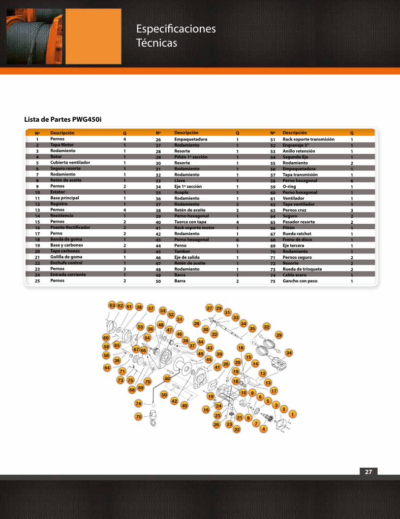
27
Nº NºDescripción DescripciónQ Q
Lista de Partes PWG450i
DescripciónPernosTapa MotorRodamientoRotorCubierta ventiladorSeguro resorteRodamientoRetén de aceitePernosEstatorBase principalRegistroPernosResistenciaPernosPuente RectificadorPernoBanda de gomaBase y carbonesTapa carbonesGolilla de gomaEnchufe controlPernosEntrada corrientePernos
EmpaquetaduraRodamientoResortePiñón 1º secciónResorteRodamientoRodamientoLlaveEje 1º secciónAcopleRodamientoRodamientoRetén de aceitePerno hexagonalTuerca con tapaRack soporte motorRodamientoPerno hexagonalPernoTamborEje de salidaRetén de aceiteRodamientoBarraBarra
Rack soporte transmisiónEngranaje 3”Anillo retensiónSegundo EjeRodamientoEmpaquetaduraTapa transmisiónPerno hexagonalO-ringPerno hexagonalVentiladorTapa ventiladorPernos cruzSeguroPasador resortePiñón Rueda ratchetFreno de discoEje terceraRodamientoPernos seguroResorteRueda de trinqueteCable aceroGancho con peso
Q4111111121114122212211312
1111111111123141161111112
1111211611113221111122211
Nº123456789
10111213141516171819202122232425
26272829303132333435363738394041424344454647484950
51525354555657585960616263646566676869707172737475
Especificaciones Técnicas

28
Especificaciones Técnicas
c. Winche PWK500
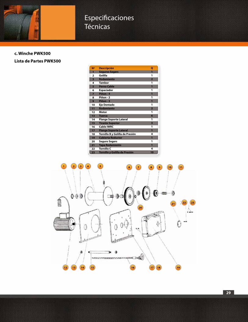
29
c. Winche PWK500
Lista de Partes PWK500DescripciónSeguros SegersGolillaRodamientoTamborPerno CableEspaciadorPiñon - 4Piñon - 2Piñon - 3Eje DentadoRodamientoMotor TuercaFlange Soporte LateralTirante SuperiorCable IWRCFlange Soporte LateralTornillo B y Golilla de PresiónCubierta ReductorSeguro SegersTapa RodamientoTornillo CTornillo y Golilla de Presión
Nº123456789
1011121314151617181920212223
Q1121111111216131141114
10
1 6
2021 22 23
1918171615141312
7 8 9 10 112 3 4 5
Especificaciones Técnicas
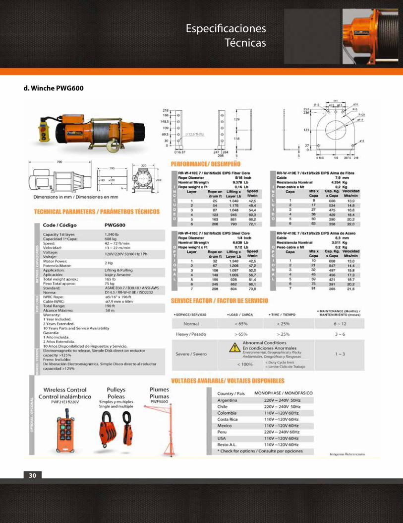
30
Especificaciones Técnicas
d. Winche PWG600
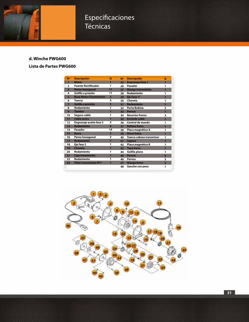
31
d. Winche PWG600
Lista de Partes PWG600
DescripciónMotorPuente RectificadorPerno hexagonalGolilla a presiónBase Motor/TransmisiónTuercaGolilla a presiónRodamientoTamborSeguro cableCable aceroEngranaje aceite fase 2RodamientoPasadorBarraPerno hexagonalRodamientoEje fase 2ChavetaRodamientoCaja transmisiónRodamientoPlato transmisión Nº1
Nº123456789
1011121314151617181920212324
Q11
1111233111126
14331111111
DescripciónEngranaje Fase 1PasadorManga transmisiónRodamientoEje Fase 1ºChavetaRodamientoPorta BobinaPernosResortes frenosEnchufe cableControl de mandoBobina frenoPlaca magnética ADisco frenoTuerca cabeza transmisorSeguro Placa magnética BTapa frenoGolilla planaPernosPernosManga frenoGancho con peso
Q111111121311111111116331
Nº2526272829 30313233343536373839404142434445464748
Especificaciones Técnicas
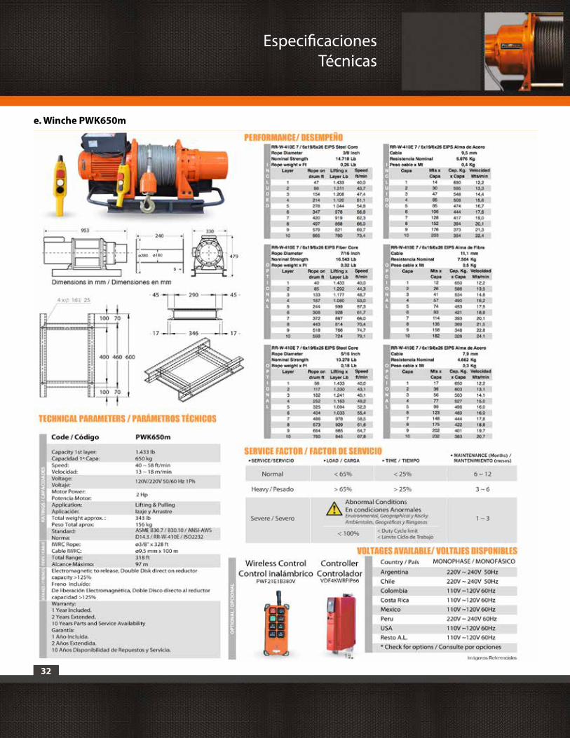
32
Especificaciones Técnicas
e. Winche PWK650m
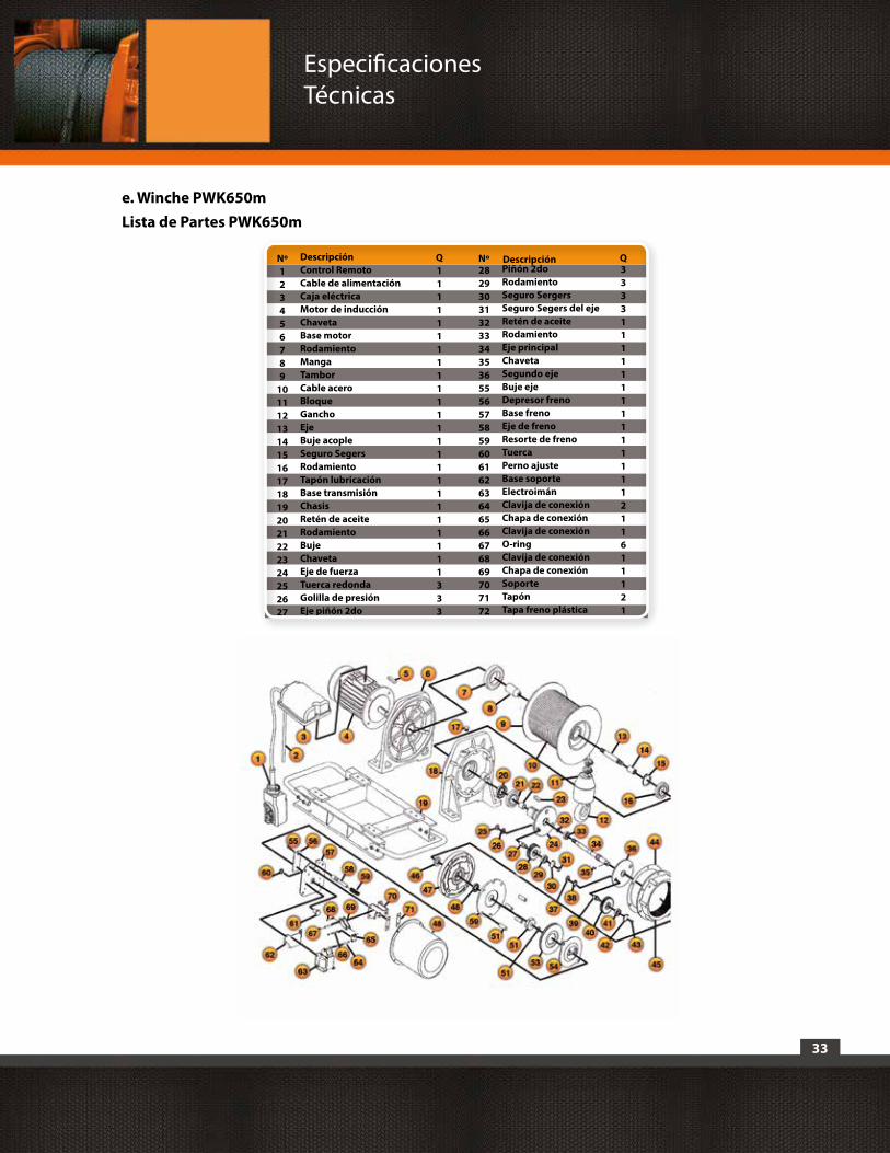
33
e. Winche PWK650mLista de Partes PWK650m
DescripciónControl RemotoCable de alimentaciónCaja eléctricaMotor de inducciónChavetaBase motorRodamientoMangaTamborCable aceroBloqueGanchoEjeBuje acopleSeguro SegersRodamientoTapón lubricaciónBase transmisiónChasisRetén de aceiteRodamientoBujeChavetaEje de fuerzaTuerca redondaGolilla de presiónEje piñón 2do
Piñón 2doRodamientoSeguro SergersSeguro Segers del ejeRetén de aceiteRodamientoEje principalChavetaSegundo ejeBuje ejeDepresor frenoBase frenoEje de frenoResorte de frenoTuercaPerno ajusteBase soporteElectroimánClavija de conexiónChapa de conexiónClavija de conexiónO-ringClavija de conexiónChapa de conexiónSoporteTapónTapa freno plástica
Q111111111111111111111111333
333311111111111111211611121
NºNº123456789
101112131415161718192021222324252627
282930313233343536555657585960616263646566676869707172
Descripción Q
Especificaciones Técnicas

34
Especificaciones Técnicas
f. Winche PWK1250
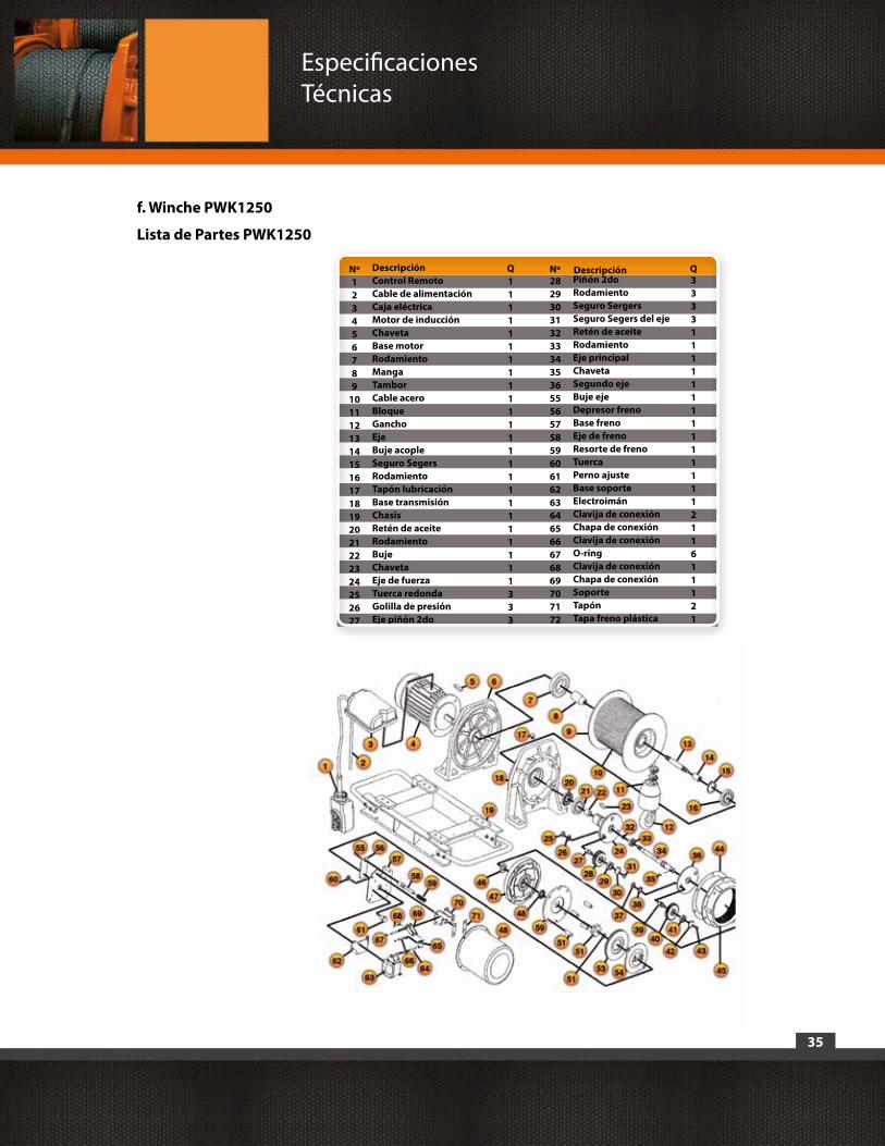
35
f. Winche PWK1250
Lista de Partes PWK1250
DescripciónControl RemotoCable de alimentaciónCaja eléctricaMotor de inducciónChavetaBase motorRodamientoMangaTamborCable aceroBloqueGanchoEjeBuje acopleSeguro SegersRodamientoTapón lubricaciónBase transmisiónChasisRetén de aceiteRodamientoBujeChavetaEje de fuerzaTuerca redondaGolilla de presiónEje piñón 2do
Piñón 2doRodamientoSeguro SergersSeguro Segers del ejeRetén de aceiteRodamientoEje principalChavetaSegundo ejeBuje ejeDepresor frenoBase frenoEje de frenoResorte de frenoTuercaPerno ajusteBase soporteElectroimánClavija de conexiónChapa de conexiónClavija de conexiónO-ringClavija de conexiónChapa de conexiónSoporteTapónTapa freno plástica
Q111111111111111111111111333
333311111111111111211611121
NºNº123456789
101112131415161718192021222324252627
282930313233343536555657585960616263646566676869707172
Descripción Q
Especificaciones Técnicas
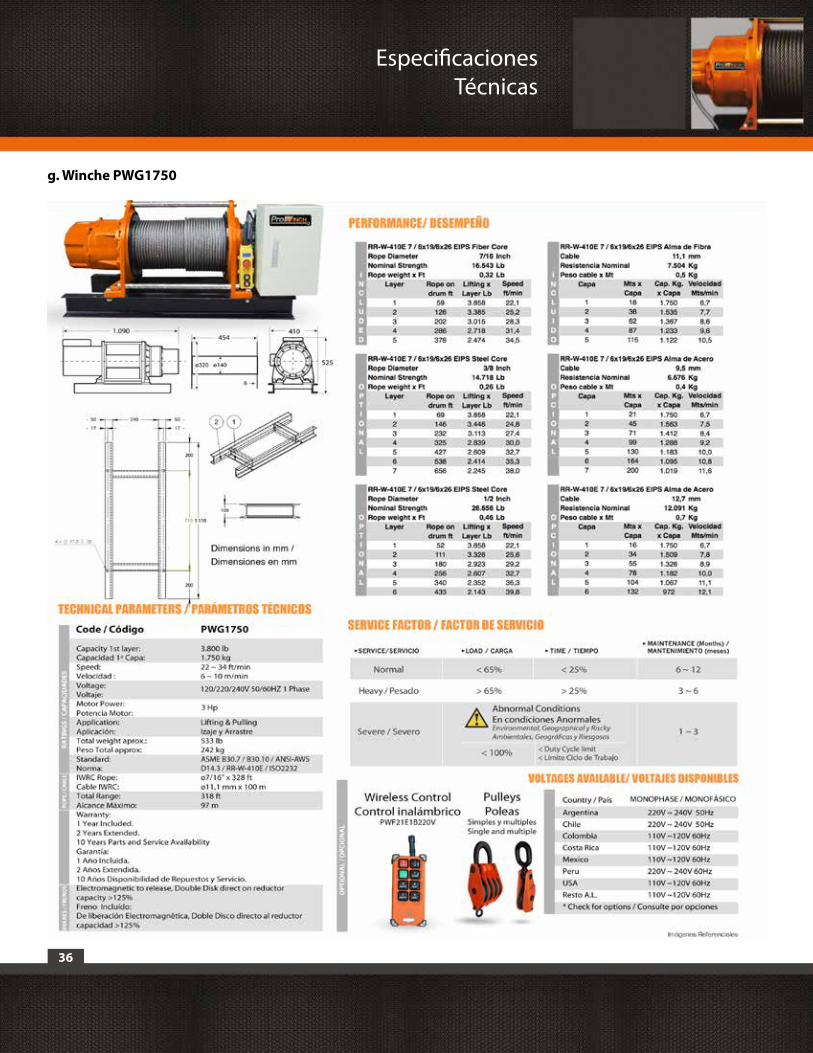
36
Especificaciones Técnicas
g. Winche PWG1750
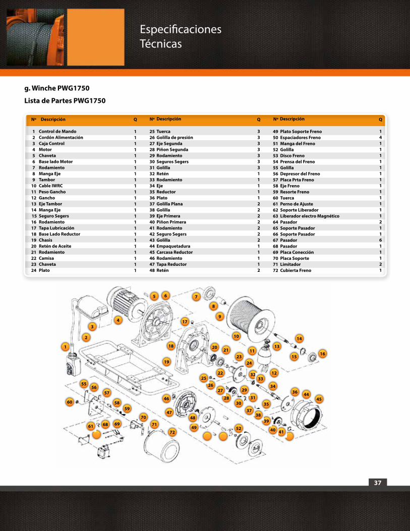
37
g. Winche PWG1750
Lista de Partes PWG1750
Descripción Descripción DescripciónNº
123456789
1011121314 15161718192021222324
Q
111111111111111111111111
Q QNº Nº
Control de MandoCordón AlimentaciónCaja ControlMotorChavetaBase lado MotorRodamientoManga EjeTamborCable IWRCPeso GanchoGanchoEje TamborManga EjeSeguro SegersRodamientoTapa LubricaciónBase Lado ReductorChasisRetén de AceiteRodamientoCamisaChavetaPlato
TuercaGolilla de presiónEje SegundaPiñon SegundaRodamientoSeguros SegersGolillaReténRodamientoEjeReductorPlatoGolilla PlanaGolillaEje PrimeraPiñon PrimeraRodamientoSeguro SegersGolillaEmpaquetaduraCarcasa ReductorRodamientoTapa ReductorRetén
252627282930313233343536373839404142434445464748
Plato Soporte FrenoEspaciadores FrenoManga del FrenoGolillaDisco FrenoPrensa del FrenoGolillaDepresor del FrenoPlaca Prta FrenoEje FrenoResorte FrenoTuercaPerno de AjusteSoporte LiberadorLiberador electro MagnéticoPasadorSoporte PasadorSoporte PasadorPasadorPasadorPlaca ConecciónPlaca SoporteLimitadorCubierta Freno
495051525354555657585960616263646566676869707172
141111111111111211611121
333333311111222222211112
23
4544
4140
3938
37
36
35
34
3233
3130
29
28
2726
25
24
20 21
22
19
18
17
1615
14
13
12
11
10
8
765
43
2
1
5249
4847
46
72
7170
696861
6059
58
5756
55
9
Especificaciones Técnicas

38
Especificaciones Técnicas
h. Winche PWK2900i
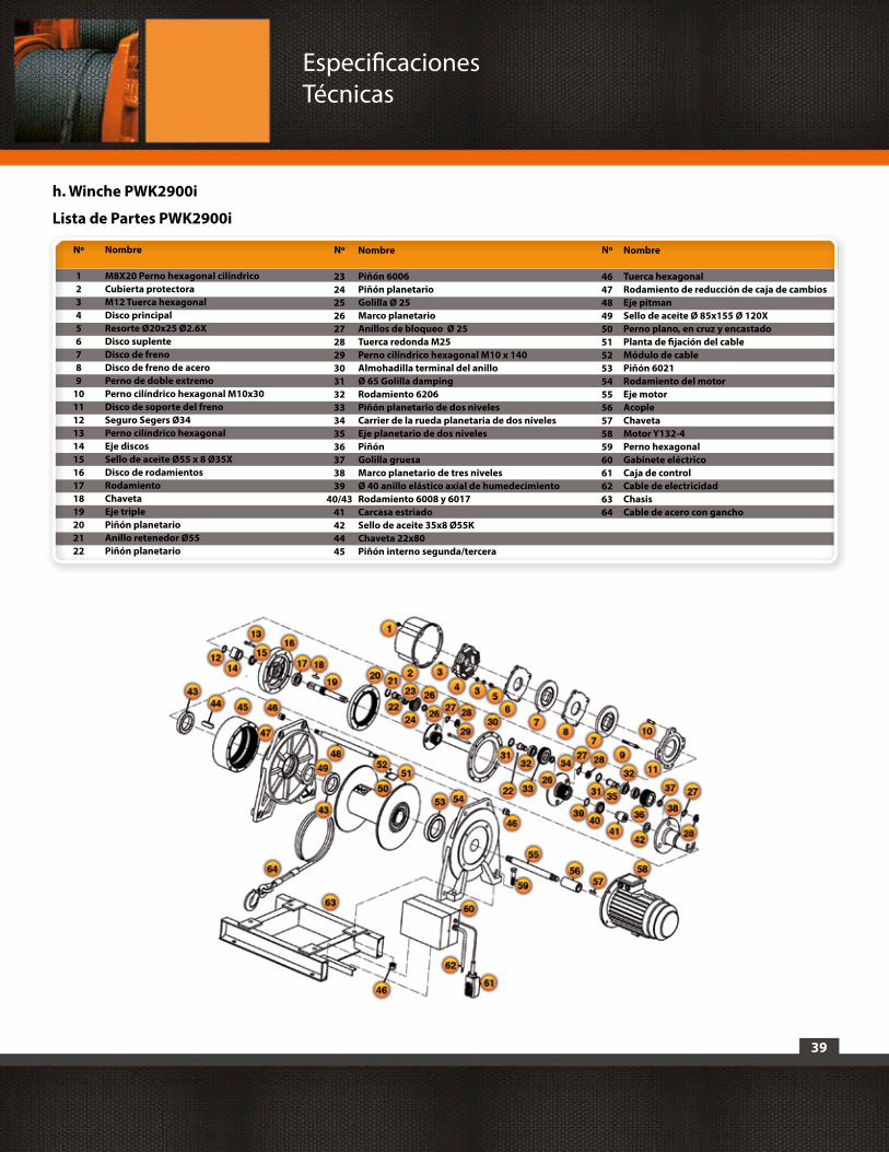
39
h. Winche PWK2900i
Lista de Partes PWK2900i
Nombre
M8X20 Perno hexagonal cilíndricoCubierta protectoraM12 Tuerca hexagonalDisco principalResorte Ø20x25 Ø2.6XDisco suplenteDisco de frenoDisco de freno de aceroPerno de doble extremoPerno cilíndrico hexagonal M10x30Disco de soporte del frenoSeguro Segers Ø34 Perno cilíndrico hexagonalEje discosSello de aceite Ø55 x 8 Ø35XDisco de rodamientosRodamientoChavetaEje triplePiñón planetario Anillo retenedor Ø55Piñón planetario
Piñón 6006Piñón planetario Golilla Ø 25Marco planetario Anillos de bloqueo Ø 25Tuerca redonda M25Perno cilíndrico hexagonal M10 x 140Almohadilla terminal del anilloØ 65 Golilla dampingRodamiento 6206Piñón planetario de dos nivelesCarrier de la rueda planetaria de dos nivelesEje planetario de dos nivelesPiñónGolilla gruesaMarco planetario de tres nivelesØ 40 anillo elástico axial de humedecimientoRodamiento 6008 y 6017Carcasa estriadoSello de aceite 35x8 Ø55KChaveta 22x80Piñón interno segunda/tercera
Tuerca hexagonalRodamiento de reducción de caja de cambiosEje pitmanSello de aceite Ø 85x155 Ø 120XPerno plano, en cruz y encastadoPlanta de fijación del cableMódulo de cablePiñón 6021Rodamiento del motorEje motorAcopleChavetaMotor Y132-4Perno hexagonalGabinete eléctricoCaja de controlCable de electricidadChasisCable de acero con gancho
Nº NºNombre NombreNº
123456789
10111213141516171819202122
2324252627282930313233343536373839
40/4341424445
46474849505152535455565758596061626364
Especificaciones Técnicas
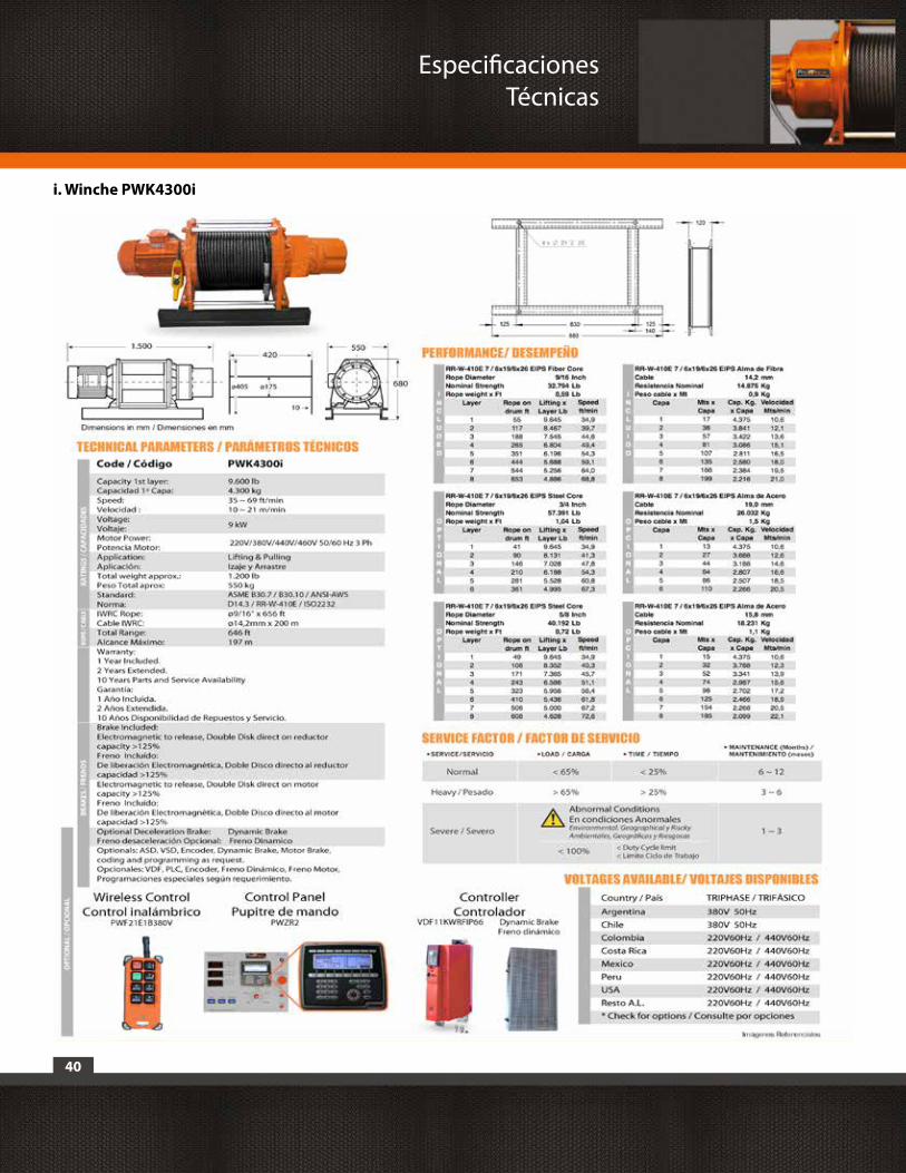
40
Especificaciones Técnicas
i. Winche PWK4300i

41
i. Winche PWK4300i
Lista de Partes PWK4300i
Nombre
M8X20 Perno hexagonal cilíndricoCubierta protectoraM12 Tuerca hexagonalDisco principalResorte Ø20x25 Ø2.6XDisco suplenteDisco de frenoDisco de freno de aceroPerno de doble extremoPerno cilíndrico hexagonal M10x30Disco de soporte del frenoSeguro Segers Ø34 Perno cilíndrico hexagonalEje discosSello de aceite Ø55 x 8 Ø35XDisco de rodamientosRodamientoChavetaEje triplePiñón planetario Anillo retenedor Ø55Piñón planetario
Piñón 6006Piñón planetario Golilla Ø 25Marco planetario Anillos de bloqueo Ø 25Tuerca redonda M25Perno cilíndrico hexagonal M10 x 140Almohadilla terminal del anilloØ 65 Golilla dampingRodamiento 6206Piñón planetario de dos nivelesCarrier de la rueda planetaria de dos nivelesEje planetario de dos nivelesPiñónGolilla gruesaMarco planetario de tres nivelesØ 40 anillo elástico axial de humedecimientoRodamiento 6008 y 6017Carcasa estriadoSello de aceite 35x8 Ø55KChaveta 22x80Piñón interno segunda/tercera
Tuerca hexagonalRodamiento de reducción de caja de cambiosEje pitmanSello de aceite Ø 85x155 Ø 120XPerno plano, en cruz y encastadoPlanta de fijación del cableMódulo de cablePiñón 6021Rodamiento del motorEje motorAcopleChavetaMotor Y132-4Perno hexagonalGabinete eléctricoCaja de controlCable de electricidadChasisCable de acero con gancho
Nº NºNombre NombreNº
123456789
10111213141516171819202122
2324252627282930313233343536373839
40/4341424445
46474849505152535455565758596061626364
Especificaciones Técnicas

42
Especificaciones Técnicas
j. Winche PWG7700
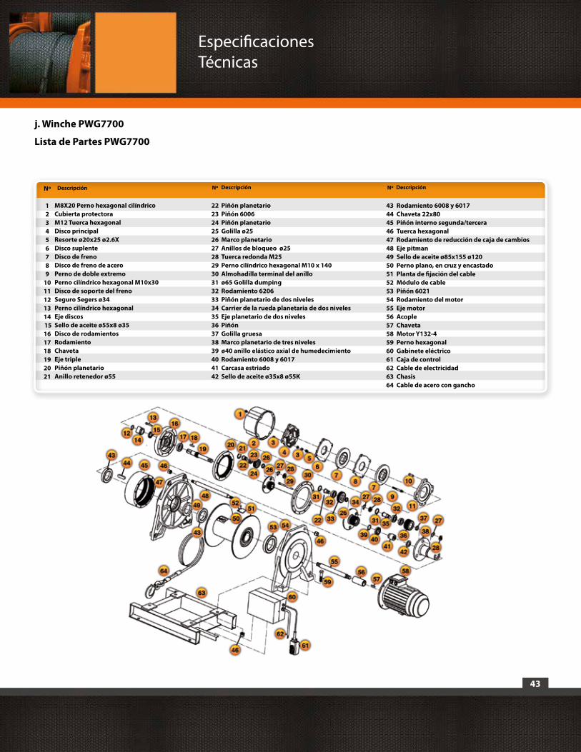
43
Descripción Descripción DescripciónNº
123456789
1011121314 15161718192021
Nº Nº
M8X20 Perno hexagonal cilíndricoCubierta protectoraM12 Tuerca hexagonalDisco principalResorte ø20x25 ø2.6XDisco suplenteDisco de frenoDisco de freno de aceroPerno de doble extremoPerno cilíndrico hexagonal M10x30Disco de soporte del frenoSeguro Segers ø34 Perno cilíndrico hexagonalEje discosSello de aceite ø55x8 ø35Disco de rodamientosRodamientoChavetaEje triplePiñón planetario Anillo retenedor ø55
Piñón planetarioPiñón 6006Piñón planetario Golilla ø25Marco planetario Anillos de bloqueo ø25Tuerca redonda M25Perno cilíndrico hexagonal M10 x 140Almohadilla terminal del anilloø65 Golilla dumpingRodamiento 6206Piñón planetario de dos nivelesCarrier de la rueda planetaria de dos nivelesEje planetario de dos nivelesPiñónGolilla gruesaMarco planetario de tres nivelesø40 anillo elástico axial de humedecimientoRodamiento 6008 y 6017Carcasa estriadoSello de aceite ø35x8 ø55K
222324252627282930313233343536373839404142
Rodamiento 6008 y 6017Chaveta 22x80Piñón interno segunda/terceraTuerca hexagonalRodamiento de reducción de caja de cambiosEje pitmanSello de aceite ø85x155 ø120Perno plano, en cruz y encastadoPlanta de fijación del cableMódulo de cablePiñón 6021Rodamiento del motorEje motorAcopleChavetaMotor Y132-4Perno hexagonalGabinete eléctricoCaja de controlCable de electricidadChasisCable de acero con gancho
43444546474849505152535455565758596061626364
j. Winche PWG7700
Lista de Partes PWG7700
Especificaciones Técnicas
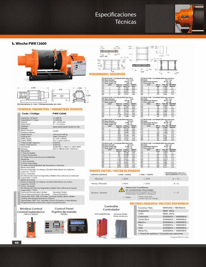
44
Especificaciones Técnicas
k. Winche PWK12600
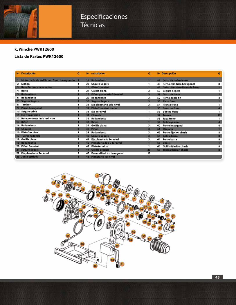
45
Descripción
Motor Jaula de ardilla con freno incorporadoMangaBase Portante lado motorBarraRodamientoRodamientoSeguro SegersTamborPerno hexagonalSeguro cableEje TransmisiónBase portante lado reductorReténRodamientoChavetaPlato 3er nivel Tuerca redondaGolilla planaRodamientoPiñón 3er nivelSeguro SegersEje planetario 3er nivelJunta estriada
Descripción DescripciónNº
123456789
1011121314151617181920212223
Q
11141221211111219333331
Q QNº Nº
k. Winche PWK12600
Lista de Partes PWK12600
2425262728293031323334353637383940414243444546
RodamientoSeguro SegersPlato 2do nivelGolilla planaPiñón planetario 2do nivel RodamientoSeguro SegersEje planetario 2do nivelPlato 2do nivel menorEje 1er nivelChavetaRodamientoReténGolilla planaPiñónRodamientoSeguro SegersEje planetario 1er nivelPlanetario 2do y 3er nivelPlato terminalGolilla presiónPerno cilíndrico hexagonalPlanetario 1er nivel
1113333311
113333311
20121
474849505152535455565758596061626364656667
Disco de rodamientoPerno cilíndrico hexagonalCubo cilíndrico discos de frenoSeguro SegersDisco de frenoPerno doble finPlato frenoPrensa frenoResortes frenoBobina frenoTuerca Tapa frenoGolilla presiónPerno hexagonalEtiquetaPerno fijación chasisGolilla barraPerno barraChasisGolilla fijación chasisTuerca fijación chasis
1811241141
121441888188
Especificaciones Técnicas
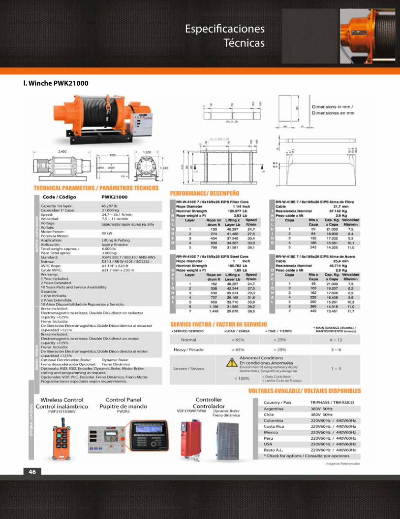
46
Especificaciones Técnicas
l. Winche PWK21000
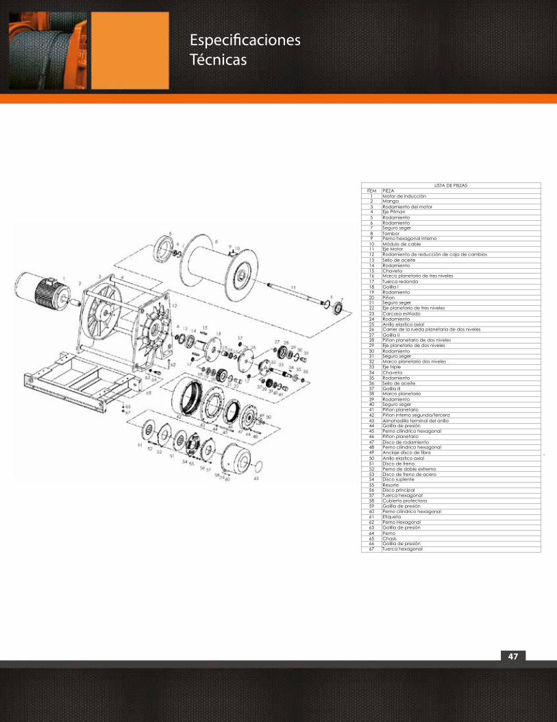
47
Especificaciones Técnicas
LISTA DE PIEZASITEM PIEZA
1 Motor de inducción2 Manga3 Rodamiento del motor4 Eje Pitman5 Rodamiento6 Rodamiento7 Seguro seger8 Tambor9 Perno hexagonal interno10 Módulo de cable11 Eje Motor12 Rodamiento de reducción de caja de cambios13 Sello de aceite14 Rodamiento15 Chaveta16 Marco planetario de tres niveles17 Tuerca redonda18 Golilla I19 Rodamiento20 Piñon21 Seguro seger22 Eje planetario de tres niveles23 Carcasa estriado24 Rodamiento25 Anillo elastico axial26 Carrier de la rueda planetaria de dos niveles27 Golilla II28 Piñon planetario de dos niveles29 Eje planetario de dos niveles30 Rodamiento31 Seguro seger32 Marco planetario dos niveles33 Eje triple34 Chaveta35 Rodamiento36 Sello de aceite37 Golilla III38 Marco planetario39 Rodamiento40 Seguro seger41 Piñon planetario42 Piñon interno segunda/tercera43 Almohadilla terminal del anillo44 Golilla de presión45 Perno cilindrico hexagonal46 Piñon planetario47 Disco de rodamiento48 Perno cilindrico hexagonal49 Anclaje disco de fibra50 Anillo elastico axial51 Disco de freno52 Perno de doble extremo53 Disco de freno de acero54 Disco suplente55 Resorte56 Disco principal57 Tuerca hexagonal58 Cubierta protectora59 Golilla de presión60 Perno cilindrico hexagonal61 Etiqueta62 Perno Hexagonal63 Golilla de presión64 Perno65 Chasis66 Golilla de presión67 Tuerca hexagonal
A A
B B
C C
D D
E E
F F
G G
H H
J J
K K
L L
M M
16
16
15
15
14
14
13
13
12
12
11
11
10
10
9
9
8
8
7
7
6
6
5
5
4
4
3
3
2
2
1
1
WINCHE IZAJE INDUSTRIAL21000kg
01PWK21000 A1
Equipos de Izaje Prowinch Chile Spa.Parque Riesco, 3407
Santiago - Chile
INTERPRET GEOMETRICAL TOLERANCING PER:
MATERIAL:
DIMENSIONS ARE IN MILLIMETERS.TOLERANCES: LINEAR: ± ANGULAR: ±
DO NOT SCALE DRAWING
FINISH:
UNLESS OTHERWISE SPECIFIED:
COMMENTS:
APPROVED:
PROJECT:
CHECKED:
DATENAME
DRAWN:
REV: SIZE:
WEIGHT: SHEET 1 OF 1SCALE:
CODE:
TITLE:

48
m. Winche PWK21000XL
Especificaciones Técnicas
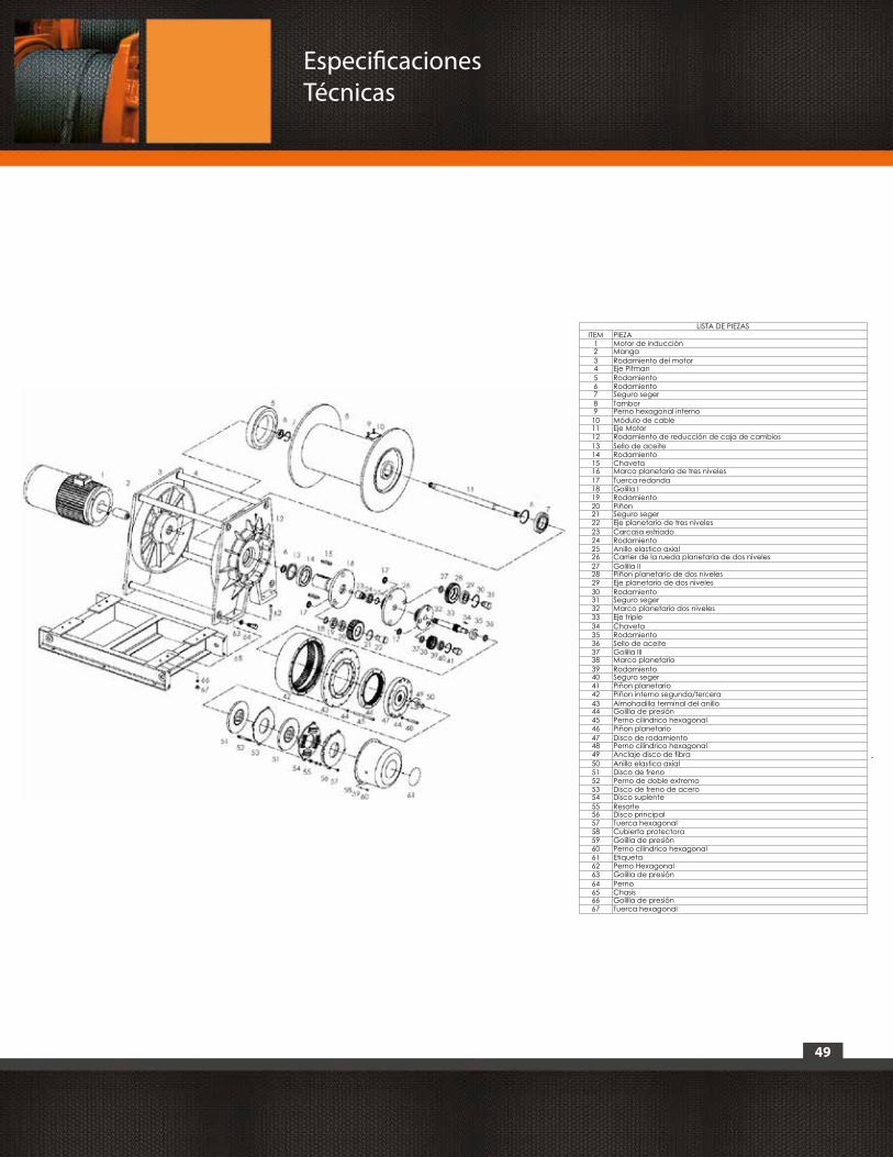
49
Especificaciones Técnicas
LISTA DE PIEZASITEM PIEZA
1 Motor de inducción2 Manga3 Rodamiento del motor4 Eje Pitman5 Rodamiento6 Rodamiento7 Seguro seger8 Tambor9 Perno hexagonal interno10 Módulo de cable11 Eje Motor12 Rodamiento de reducción de caja de cambios13 Sello de aceite14 Rodamiento15 Chaveta16 Marco planetario de tres niveles17 Tuerca redonda18 Golilla I19 Rodamiento20 Piñon21 Seguro seger22 Eje planetario de tres niveles23 Carcasa estriado24 Rodamiento25 Anillo elastico axial26 Carrier de la rueda planetaria de dos niveles27 Golilla II28 Piñon planetario de dos niveles29 Eje planetario de dos niveles30 Rodamiento31 Seguro seger32 Marco planetario dos niveles33 Eje triple34 Chaveta35 Rodamiento36 Sello de aceite37 Golilla III38 Marco planetario39 Rodamiento40 Seguro seger41 Piñon planetario42 Piñon interno segunda/tercera43 Almohadilla terminal del anillo44 Golilla de presión45 Perno cilindrico hexagonal46 Piñon planetario47 Disco de rodamiento48 Perno cilindrico hexagonal49 Anclaje disco de fibra50 Anillo elastico axial51 Disco de freno52 Perno de doble extremo53 Disco de freno de acero54 Disco suplente55 Resorte56 Disco principal57 Tuerca hexagonal58 Cubierta protectora59 Golilla de presión60 Perno cilindrico hexagonal61 Etiqueta62 Perno Hexagonal63 Golilla de presión64 Perno65 Chasis66 Golilla de presión67 Tuerca hexagonal
A A
B B
C C
D D
E E
F F
G G
H H
J J
K K
L L
M M
16
16
15
15
14
14
13
13
12
12
11
11
10
10
9
9
8
8
7
7
6
6
5
5
4
4
3
3
2
2
1
1
WINCHE IZAJE INDUSTRIAL21000kg
01PWK21000 A1
Equipos de Izaje Prowinch Chile Spa.Parque Riesco, 3407
Santiago - Chile
INTERPRET GEOMETRICAL TOLERANCING PER:
MATERIAL:
DIMENSIONS ARE IN MILLIMETERS.TOLERANCES: LINEAR: ± ANGULAR: ±
DO NOT SCALE DRAWING
FINISH:
UNLESS OTHERWISE SPECIFIED:
COMMENTS:
APPROVED:
PROJECT:
CHECKED:
DATENAME
DRAWN:
REV: SIZE:
WEIGHT: SHEET 1 OF 1SCALE:
CODE:
TITLE:

50
Especificaciones Técnicas
n. Winche PWG23700
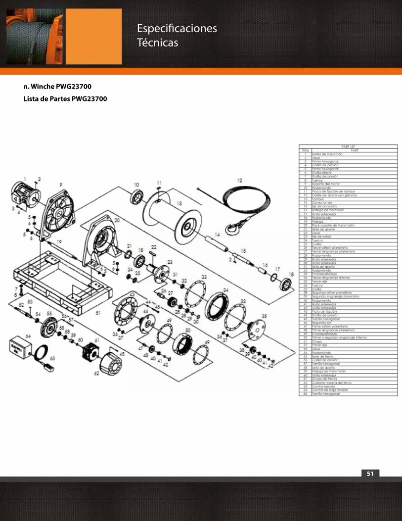
51
n. Winche PWG23700
Lista de Partes PWG23700
Especificaciones Técnicas

52
![[XLS] · Web viewHOIST HOIST EQUIPMENT ACTUATOR, MLG HOIST HOIST EQUIPMENT - ACTUATOR, MLG HOIST HOIST - CARDAN PIN HOIST HOIST-CARDAN PIN HOIST HOIST-DEVICE,FLAP TRACK 2-5 HOIST](https://img.pdfslide.net/doc/110x75/5b1fa5177f8b9aa64c8b4800/xls-web-viewhoist-hoist-equipment-actuator-mlg-hoist-hoist-equipment-actuator.jpg)