Embed Size (px)
Citation preview
NEDC 21974Class i
November 1976
% i: ' < '%?' ' "', '
, migt.. g;h. , . e, --,,s
.<syp w - '
,- ,<
sBIG ROCK POINT CORE SPMY s
-
SPARGER AND STEAVI BAFFLE g(DESIGNI REPOR 7gw- ei
@jisNOTICE -- ?
-
|*THE ATTACHED FILES ARE OFFICIAL RECORDS OF THE
|$ sDIVISION OF DOCUMENT CONTROL. THEY HAVE BEEN R. E. LEG ATE i
%CHARGED TO YOU FOR A LIMITED TIME PERIOD AND kMUST BE RETURNED TO THE RECORDS F ACIL IT Y
k||[BRANCH 016. PL E ASE DO NOT SE ND DOCUMENTS .;CHARGE D OUT THROUGH THE MAIL. REMOVAL OF ANY SPAGE(S) FRCM DOCUMENT FOR REPRODUCTION MUSTBE REFERRED TO FILE PERSONNEL. #"~fy . - < "N'
DEADLINE RETURN DATE
wnwP.-.. .:. , _ . . . _ , ,, , , r .
W.UL I d it J 6d i L:.k .bd hb*-
- -n.
p-erease q p = , e =' a = r r gefP=' , {i .} / , ,.
*'#''"'""''~"'''''.. . . . . . . - .. . .... . .-
f { P '%I k=O RECORDS F ACILITY BR ANCH
|
78112700ViGENER AL h ELECTRIC
.. . .
w%., ,. O .,,.y - -- N m i *7
-
N F DC-21974Classi
Novemter 1978
BIG ROCK POINT CORE SPRAYSPARGER AND STEAM BAFFLE
DESIGN REPORT
N ~{,~ m Qcci u I\T bAbOG;;_ p.
s()Ho099R. E. LEG AT:s
~. _ ' - T$ , n <,
.- '' -t. -Accrovec: -
R. J. Brancon, ManagerOcerating P! ant Engineering
'.- ,
, , , . . _ ,
!6.. . ' '. . .
.
>, .;
NUCLE AR ENERGY ENGINE E AiNG DIVtSiON = GE NE R AL E LE CTP 60 COvr AN v5AN JOSE. CA LIF ORNI A 95125
GEN ER AL h ELECTRIC

DISCLAIMER OF RESPONSIBILITY
-
- - .- . ,.-- . ,,., .-., d. . -y . - , . . . ... w.-,.3 ,._ -.- .a ,. v.......,, _ , . ,.- w . . . . .. . .. ... . .
.. w . . y3 <.- ** w w ., .e . =mm g e e'', ; e g e.g .:w . . .
a. - *= . " ~- w a-;m , e-.> -oP . ~ + eng .om.,em * w *e e - g ew.
. . >. W
0- 8 -p'n4 y e & .J = .bw.f 9- #Mg
W + W $ e- 3. d=g p% e g -s_e #'u% P p gM re% eg { A g d=
OBO,ggrw g85I E wp9FL88 f ar F8kP g ( g 54 O" w
*g,. . w ws .3 . . 9% 9% J ..w,* 5 * ***C'm** *>[*0
-
W M *
..$w ' .0 % ; J .f( .- *h g 0% O .~ 9 994 & .O.Mw..-*b..'' *^P09***m- [*[.@,'..(( .-*g**
....
.v.g , . .e c. .= - e. m. e w,-w,-g,. m. 2 mme,, e_ . -p 6-o-- . -=y. e,,. s .( o, .e -3,. ,ac.,,a. -.
- - e - -
r F e q ew@g ma, a ,s.g*" P.e ps g aw e y .s .-- y. . t . .m Mr(
a-e.,, g m. 4 .m a = ~ , eg g3 .sw.
e. - -. - .- - 2 n 4. .. ,
aa * ees. - o. .-e-C ; e .e-e g >a .q -. , yea--a.s., - gs., .- , -,
--m, em g .o g -* .z. ey e * - r e .:. v .. n m$+,.$cm 4-m *m $ ** .* .* smp e r.
. . . . . -- - - - -
& m.
6
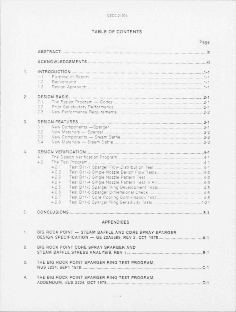
NEDO 21974
TABLE OF CONTENTS
Page
ABSTRACT. . . . . . . . .. . . . . . .. .. . ... i x
ACKNOWLEDGEMENTS .. . . . .. . . . . .. ... . . . .. . .. ..xi
1. INTRO DU CTIO N . . . . . . . . .. . .. . . . .. . . . . . . . .. . ..1-11.1 Purpose of Report. .1-11.2 Backgrounc . .1-11.3 Design Aporoach. .1-1
2. DESIGN B ASIS.. .. . . . ... .. .. ........ . . . . . .. ... .. .. .. 2-12.1 The Repair Program - Coces . .2-12.2 Pnor Satisf actory Performance .2-12.3 New Performance Requirements. .2-2
3. DESIGN FEATURES. . . . . . . . . . . . . . . . . . . .. . . . . . . . . . . . . . . . 3-13.1 New Components -Sparger . .3-13.2 New Matenals - Sparger . .3-23.3 New Components - Steam Baffle.. .3-23.4 New Materials - Steam Eaff!e. .3-3
4. DESIGN VERIFICATION.. . . . . . . . . . . . . . . .. . . . . . . . . . . .. .. . . . 4-1
a.1 The Design Venfication Program . .414.2 The Test Program. .4-1
4.2.1 Test B11-1 Sparger Flow Distnbution Test . . 4-14 2.2 Test B11-2 Single Nozzle Bench Flow Tests.. .4-24.2.3 Test 811-3 Single Nozzle Pattern Test . .4-24 2.4 Test B11-4 Single Nozz!e Pattern Test in Air. .4-34.2.5 Test B11-5 Sparger Ring Development Tests. .4-54.2.6 Test B11-6 Sparger Dimensional Check. .4-64 2.7 Test B11-7 Core Coc!ing Confirmatior Test. .4-64.2.8 Test B11-S Sparger Ring Sensitivity Tests. .4-24
5. CONCLUSIONS . .. . . . .. . . . . . . . . . . . . . . . . . . . . . . . . . . . . . . . . ....S-1
APPENDICES
1. BIG ROCK POINT - STEAM BAFFLE AND CORE SPRAY SPARGERDESIGN SPECIFICATION - GE 22A5589, REV 2, OCT 1978. . . . . . . . . . . . . .. ..... ..A-1
2. BIG ROCK POINT CORE SPRAY SPARGER ANDSTEAM B AFFLE STRESS AN ALYSIS, REV 1. .. ... . . . . . . . . . . . .. ...... ..............B-1
3. THE BIG ROCK POINT SPARGER RING TEST PROGRAM,NUS 3234. SEPT 1978. . .......C-1. . . . . . . . . . .. .. . . . . . . . . . . . . . . . . . . .
4. THE BIG ROCK POINT SPARGER RING TEST PROGRAM,ADDENDUM,14US 3234, OCT 1978. .. ..... . . . . . . . .. . . . . . . ...............D-1
2:6- -IV-

% Eat:19u
LIST OF TABLES
Table Page
4-1 Sensitiv:ty Test Program .4-25
-, s.
NEDC 21974
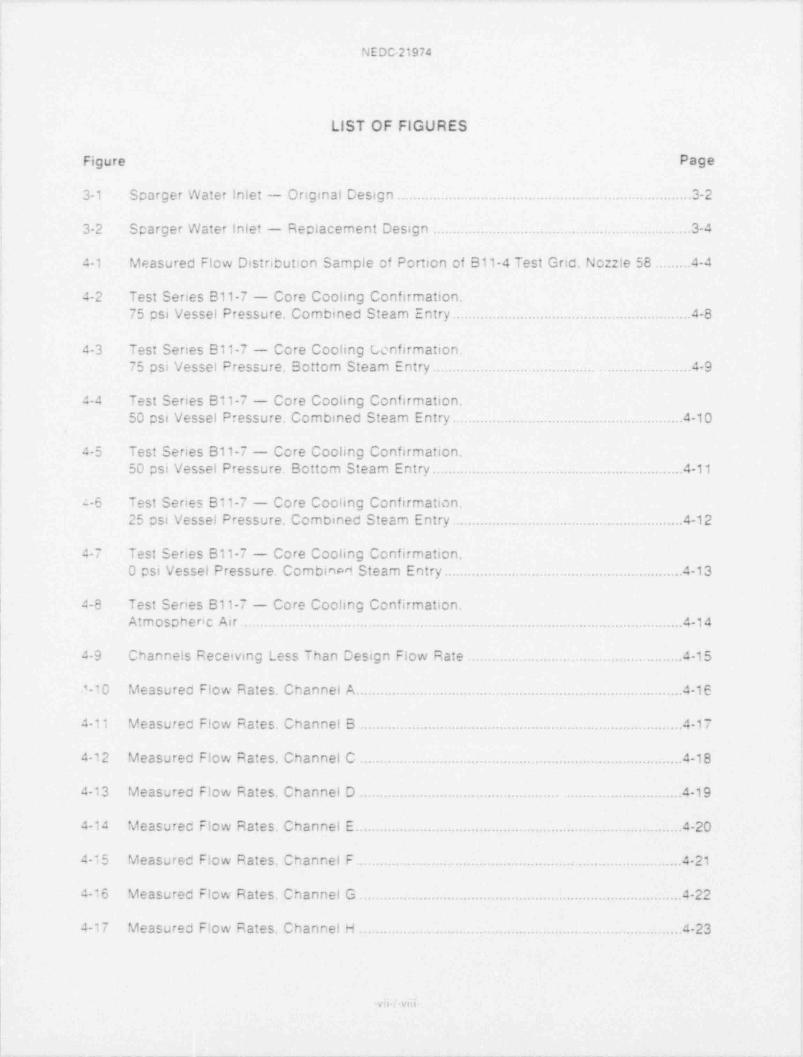
LIST OF FIGURES
Figure Page
3-1 Sparger Water inlet - Original Design . .3-2
3-2 Sparger Water Inlet - Rectacement Design . .3-4
4-1 Measured Flow Distribution Sample of Portion of B11-4 Test Gnd. Nozzle 58. .4-4
4-2 Test Series B11-7 - Core Cooling Confirmation.75 psi Vessel Pressure. Combined Steam Entry. .4-8
4-3 Test Series B11-7 - Core Cooling Lenfirmation.75 psi Vessel Pressure. Bottom Steam Entry. .4-9
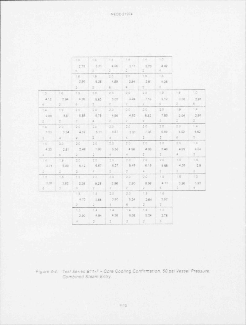
4-4 Test Series 811-7 - Core Cooling Confirmation.50 psi Vessel Pressure. Combined Steam Entry. .4-10
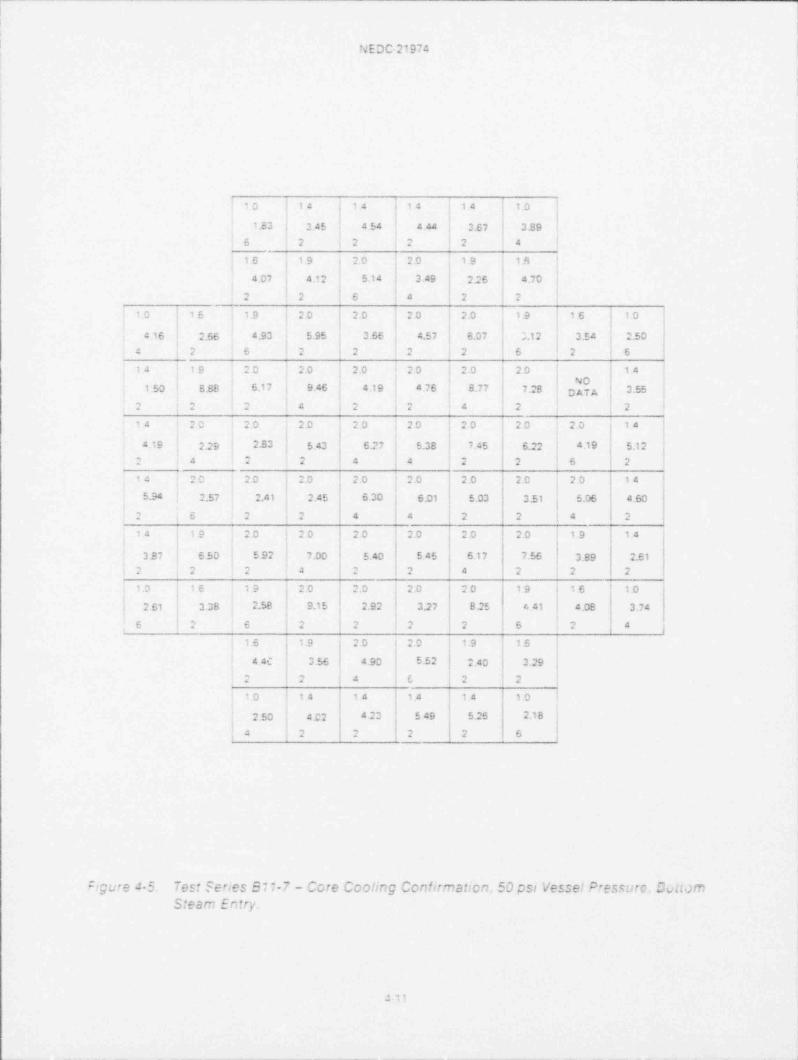
4-5 Test Series B11-7 - Core Cooling Confirmation.50 psi Vessel Pressure. Bottom Steam Entry. .4-11
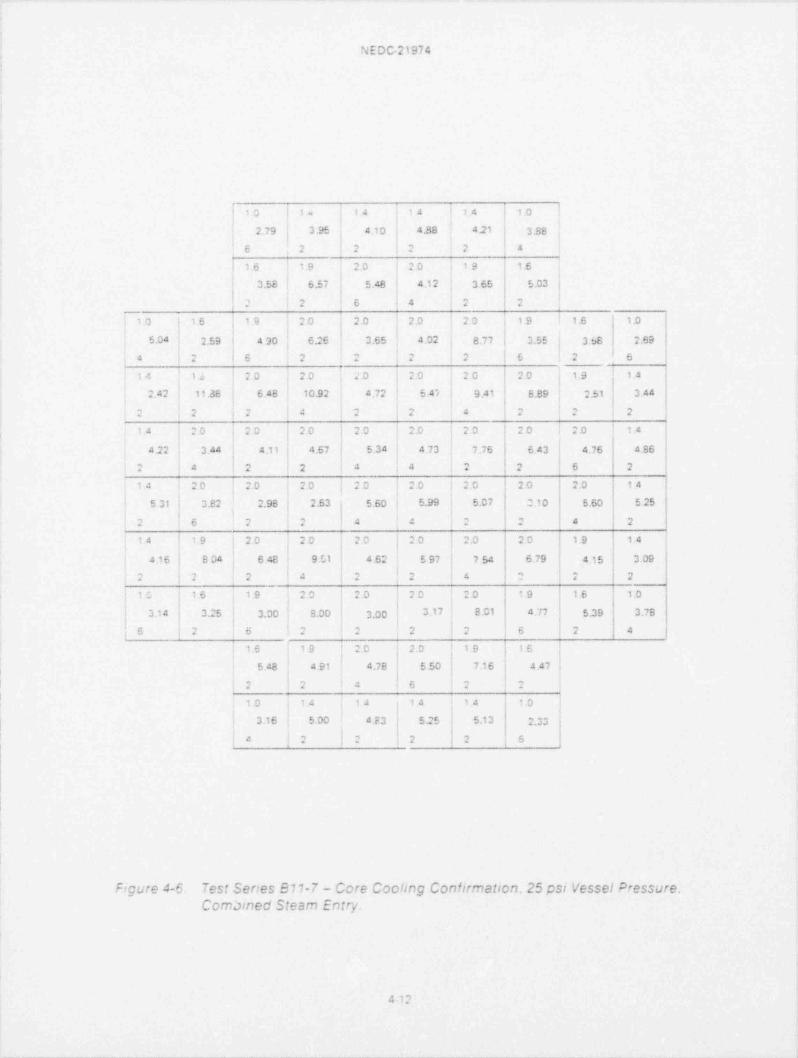
-6 Test Series B11-7 - Core Cociing Confirmation.25 osi Vessel Pressure. Combined Steam Entry. .4-12
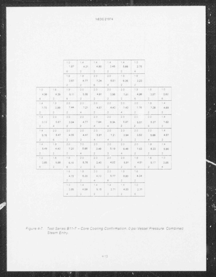
4-7 Test Series B11-7 - Core Cooling Confirmation.O psi Vessel Pressure. CombinM Steam Entry. .4-13
4-8 Test Series B11-7 - Core Cooling Confirmation.Atmospheric Air .4-14
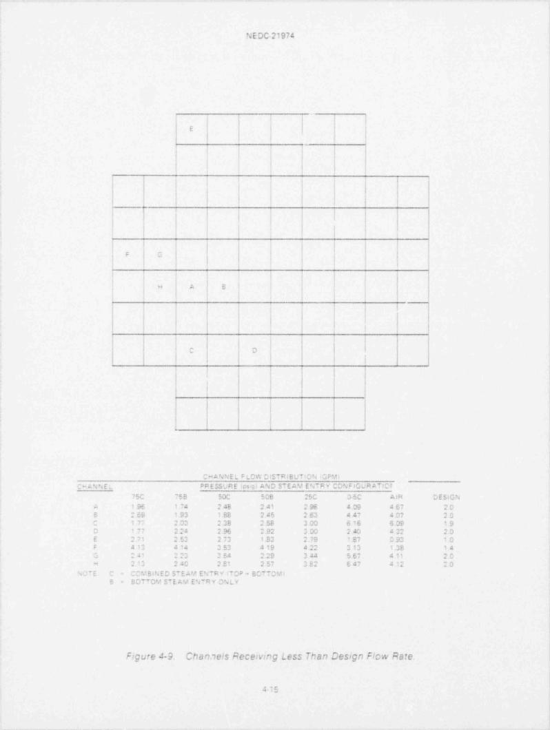
4-9 Channels Receiving Less Than Design Flow Rate . .4-15
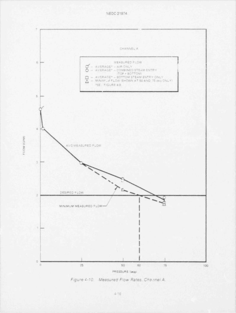
^10 Measureo Flow Rates. Channel A.. . 4-1e
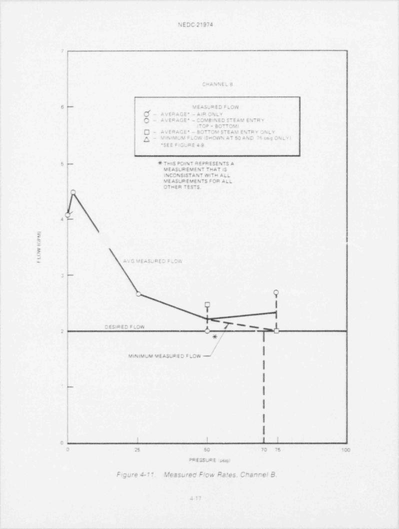
4-11 Measured Flow Rates. Channel B .4-1T
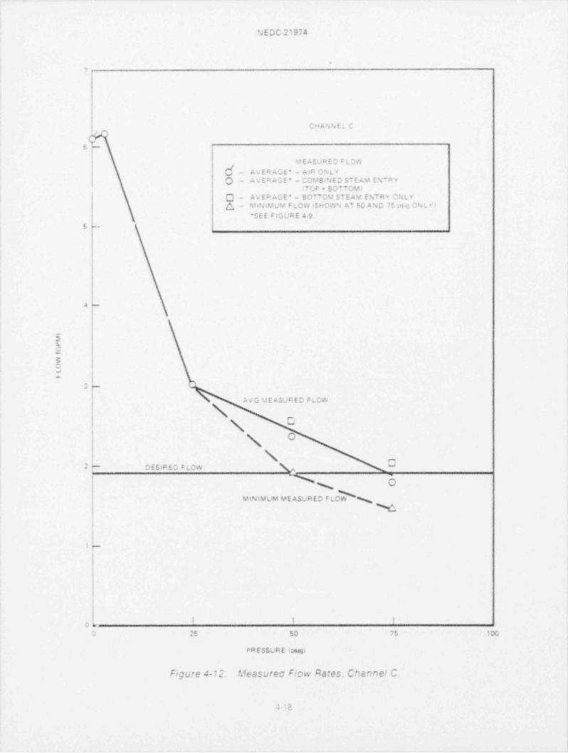
4-12 Measured Flow Rates. Channel C . .4-18
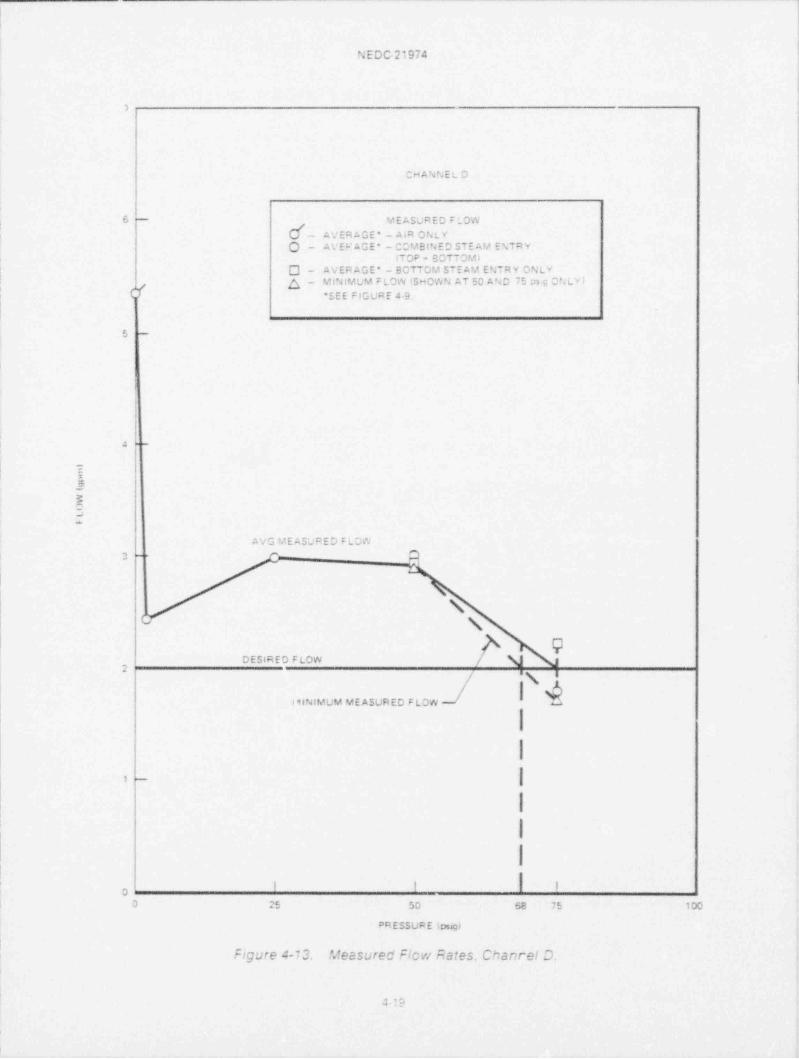
4-13 Measureo F!cw Rates. Channel D . .4-19
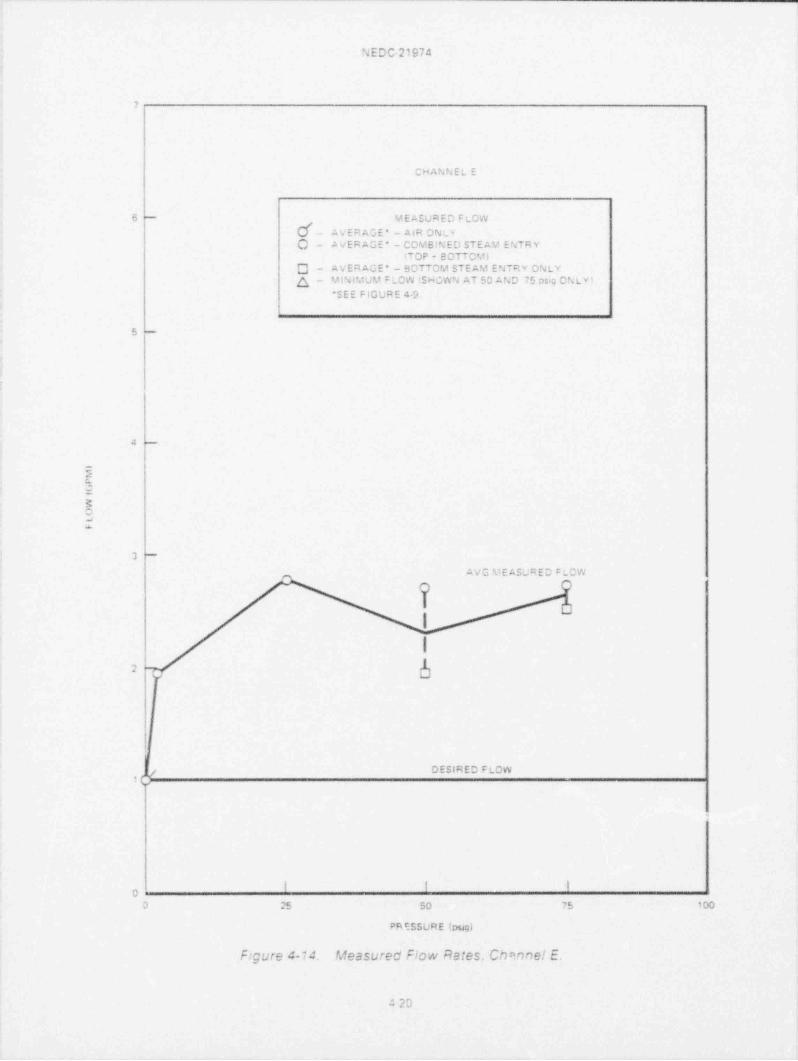
4-14 Measured Flow Rates. Channel E. .4-20
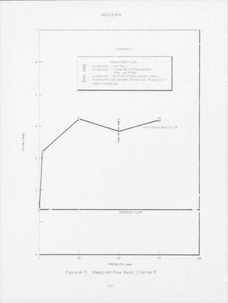
4-15 Measured Flow Rates. Channel F. .4-21
4-16 Measured Flow Rates. Channel G . .4-22
4-17 Measured Flow Rates. Channe! H . .4-23
n. ,,
NEDC 21974
ABSTRACT
This report cescrices the design effort undertaken to provide e coreaoray sparger having improved flow cistribution characteristics forthe Big Rock Point (BRP) Boiling Water Reactor.
The design of the core sprsy sparger (hereinafter called "thesoarger'') was based on an expenmental testing program. A fullsizesparger was installea in a specially constructea test vessel of aconfiguration simulating the BRP reactor vessel. With this testequipment it was possible to perform tests duplicating the range ofsparger operating conditions including sparger flow and reactorvesselcressure and steam environment. Testing consisted cf etfect-ing an operating concition in the test vessel, actuating the coresoray system and measuring the flow of water received by theindividual simulated fuel buncles in the test vessel. During a seriesof developmental tests the no::le aiming pattern was adjusted untilan actimum flow distnbution was octained. Sucsequently, a seriesof des!gn configuration tests were conducted to estaclisn a catabase. Finally a senes of sensitivity tests were performed to evaluatethe system sensitivity to (1) factors which might De introduced in|actication of the new sparger and (2) conditions that might occuras a result of installation of the new soarger in the BRP reactorvessel.
Tne existing (old) sparger ; known to nave two camagea elbows: anexpected less than cotimum core coverage; and an imprec:se doc-umentation of the existing pattern. This reolacement was under-taken to correct this situation. The sparger and the steam batfle arenot known to nave any other defects after 17 years of service,therefore, the new sparger and steam Def!Ie are essentially re-placements in kind
.a .w
w-, ,,. ~ ,c.
1.0 INTRODUCTION
1.1 Purpose of ReportTne pur;cse of inis rescriis :c cescrice in cetaJ ine scc;e anc resu::s of ine cr: gram cces;gn a rea core scra) scarger (scarger, f or *ne Big RccW Pcmt ,EPP) Scihng Wa:erPeacic" Tn's rescri a!so cescnces t e cesign of ne ERP Steam Eaffle, cat'|ei T e ca+f emil ce reciacec to mmim:ce personnel racrat en excesure anc to ease f; up prociems
carmg sparger reciacement
1.2 BackgroundTne ERP reactor nas !Ao core scray systems: me rmg sparger system (suoject of inisreport) anc the recuncant core spray sys:em Tne cesign anc repiacement of :ne recun-cant system nas ccmc|etec cu"ing 1977 The recuncant system was ces.gnec excer-mentaHy usmg a test f ac:hty constructe for this exper: mental program. The test f ac,htyprovices reactor vessel pressure cver *ne sparger ccerating range. The f acdity crovicesine cacacmty for full scale sparger test:ng in a steam environment.
Cne :m;criant ocservation f rom :ne recuncant core scray sys:em expenmental crogramwas !nat tne core scray f!cw distr cut;cn from a s*eam test was cifferentinan a s:milar:estm air. Censumers Power Company mace a decision to cudc an exact cuphcate of ineexistmg scarger anc test it in tne steam f acility to cetermme the acecuacy cf *ne ex:stmgnng scarger. The test results snowec :nat the core scray c:stncut:cn coulc ce imcrevec.anc ces gn of a new scarger w as initiatec.
1.3 DeC3n ApproachTLe casic accroach was to reaim :ne 36 scarger nozctes. A comprenenswe stucy wasuncertaken to evaluate. frcm an engineermg anc cost stanc;cmt. the feasic:hty ofseverai ccsste!e realmmg meinccs witnin ne ces.gn restramts.
Cesign restra:nts mcluced
a. Surf ace rac:at;cn levei cn sparger anc caff!e estimatec to ce a ER.
sS 7 3.. . v s , 2, . -. a i i ,s a i a a- s c - * ^ c. ^ = r - c r ~^ " *. c ^ ^ s *. u c '. e d y ^ a +* 'l c =~' *.~^ ^ rt- ,, .sc.wv. .-p . .. . w v.
Olate.
c. Ccncern :nat cc!c wors:rg cf nczcie e! cows cy cencmg couic incuce ,nter-granular s:ress corrosion cracking.
d Ccncern that metal galhng may occur Anen turning uniucricatec inreacedconnec* ions.
Ces;gn al*ernat:VCs cors:ce"ec
Assur"mg **at the rearming Aculo ce accomphshec Arth (1) tne sparger remammg nciace m ine vesse! anc (2) *ne scarger ceing removec from ine vessel, tne fchc Airgai:E"nathes Ae'e evalLatec:
a. Er.nc eic Cws *U reair"~
c. Ins:ali flow cefiec cr3 cn eacn noccle:
1
' EDC 21974.
c. Remove existing nczzfes arc elco As and replace hitn new components:
c P'ug ex: sting r.ozzfes and instail new elecws and new nczz!es.
Tnese aiternatnes were ejectec The more s:gnificant negative consicerations aresuminarizec teicw
a. Peaim cy tencmg.
(1) Wou!c cause strain narcening anicn could induce intergranular stresscorrosien cracking (IGSCC).
(2) Could cnmp elbow affecting nozz!e ficw
(3) Could crack tack welc. Inspect;cn is cifficult.
c Install ceflectors to reaim;
n) Could cause a crevice condition wnicn cc alc incoce IGSCC
(2i Wouic require uncerwater structural weld L
c. Remove existing elbows anc nozzles anc replace
(1) Physical lengins of the elbows are too snort for remote cuttirw
(2) Woulc ce cifficult to reinstall with correct a; ming ang!e.
c. Plug existing nozzles-mount new e! bows anc nozzies:
(1) Would cnange scarger thermal.nycraulic ciaracteristics
2) Would recuire underwater anthng. tapping anc welcing
(3) Difficult to reinstall aitn correct aiming angle.
Tne feasibility stucy a!so accressed replacing tne sparger anc ret. sing the existing baffle.This acOrcacn would assure cor ect sparger nczzle aiming wnich coula ce venfled byseverai prcven means pnor to installation in the reacter vessel Tne reuse of the existingbaffle au snown to hawe several cisaavantages and several advantages. The cisacvan-tages inciacec (1) cersonnel ractating exposure cunng sparger removal and rep! ace-ment anc 42) a poss:cihty that the new sparger Aculd not fit tne existing caffle. Theacvantages inc!uced (1) lower hardware costs by not replacing the caffle anc (2) nozzleaiming pattern will nave teen vented by test.
Basec on their concen, for minimum radiation for personnel minimum nsk. and
minimum cutage cntical patn t4me. Consurners Power Company elected to purchase aew caff!e as Aell as a new scarger.
t2
N E DC-21974
2.0 DESIGN BASIS
2.1 The Repair Program-Codes
The BRP Steam Baffle and Core Spray Sparger are to be replaced in accordance with therequirements of ASME Section XI.1971 Edition. Winter 1972 Addenda. The replacementwill be undertaken to provide a new core spray sparger having improved core flowdistribution characteristics with guidance for Replacement and Pepair taken from IWA7000 of ASME Section XI.1974 Edition. Summer 1976 Addenda.
The BRP Reactor Vessel was designed f abricated and N-stamped in accordance with theASME Boiler and Pressure Vessel Code. Section I.1959 Edition. Code Cases 1270N.1271 N and 12373N were specified The vessel was N-stamped in 1961. The Reactor Vesselwas constructed in accordance with the requirements specified in the Design Specifica-tion DP19889 (GE).
The BRP core spray sparger was designed and fabricated in accordance with the re-autrements of AS A B31.1-1955.Tne steam baffle was designed in accordance with soundengineering practices with a one-fourth scale testing program to verify the hydraulicdesign. The replacement core spray sparger is to be designed and fabricated in accor-dance with ASA B31.1-1955. The steam baffle is to be an identical replacement exceptthat materials and material processes will be as described below.
Welding to the pressure vessel will not be required for this replacement. Welding of thesparger sections, studs and hold down bolts will be performed in accordance with ASMESection (1.1971 Edition. Winter 1972 Addenda.
All welding material will meet the requirements of NB-2400. ASME Section Ill.1977Edition. Summer 1977 Addenda.
All welds will be examined by liquid penetrant within the limits afforded by the access andstructure. This non-destructive examination will be in accordance with ASME Section III.1974 Edition. Summer 1975 Addenda. NB-5000.
Welds mace to prevent loosening nuts from bolts will be visually examined and shall besubjected to a mechanical proof load test.
All materials used for the new steam baffle will meet the requirements of applicable ASTMor ASME material specifications with additional requirements specified to minimizesusceptibility to intergranular stress e errosion cracking.
2.2 Prior Satisf actory Performance
The BRP Reactor has been in operation approximately seventeen years.The ring spargercore spray system has not been actuated during this period, However, it has beensubjected to the reactor environment with no observed design problems. The bafflesimilarly has been in the reactor environment for approximately seventeen years. Acaffle-plate latch modification was incoroorated early in plant life when the baffle plateswere found 17 the open Oosition. Two specimen oaskets were welded to the baffle
support plate in ine early sixties Each baffle Olate door was originally built having twohandles. One handle was removed from each Daffle plate in 1977 to remove an inter-
21
N E DC-2 i s ,4
ference to flow from the new reoundant core spray system. The Caffle in its presentconfiguration nas no known cesign prctiems.
2.3 New Performance Requirements
Basec on a recent eva!uation by Corisumers Power Company the available sparger flowrate versus reactor pressure cnaracteristics have been established as
Pressure (psig) Flow Rate (gpm)75 29250 35925 416
5 4560 466
Consumers Power Company also establisnec, as a goal. the core spray flow rate for eachfuel tundle. This information is shown on Page 8 of the Design Specification. GE22A5589. (See Appendix 1 ).
Tne maximum allowable leax rate for the piping connecting the core spray noz:!ethermal sleeve to the sparger has been estaclished at 8 gpm. Though not a new perfor-mance requirement. a reauirement has been established in the design to incorporatefeatt res that will enable the owner to verify that the core spray nozzle alming points donot shift during the operating life of the plant. This verification can be done duringselected refuehng outages.
22
N E CC21974
3.0 DESIGN FEATURES
3.1 New Components - Sparger
Tne new sparger nas been designed to duphcate the thermal nydraulic characteristics ofthe existing sparger. Dimensionally the new sparger will ce a dLohcate of the sparger thatwas used in the flow distnoution cevelopment tests cescribed in Section 4. There are,
nowever three design changes f rom both the exist;ng sparger and the test sparger. Thefirst is a cnange in the configuration of the elbows connecting the new ring sparger to thethirty six nozzles. On the original sparger inese elbows were either a 15 cegree or a 30cegree bend.1.2 inch pipe elbow. Use of these elbows needlessly restricted flexibility forthe precise aiming of the individual nuzzles. Tne elbows used on the test sparger areswivel jointed. fu;l flow.12 inch elbows that allow nozzle aiming within a range of 25degrees. The saivel jointed elbows cannot be used for the final con iguration becausethe f riction lock device used to hold their p:e-set position was judged 10 have insufficientresistance to accidental cnange in aiming angte. The elbows used witn the new spargerare mitre cut prec:sion elbows Each elbow is faoricated to preciseiy aim the nozzle.These elbows allow three dimensional aiming flexibility. The intersect point with theupoer core plane by a projection of the nozzle flow axis is held to be within a circ |e navinga 14 inch radius
The seconc design change is a new feature of the nozzle usec on the new sparger. Thenew cesign nozzle cocy is one piece wnile Ine nozzles on tne existing sparger have a twopiece cocy The two pieces of the old nozzle are threaced 'ogether and tack weldedThese tack welds interfere with the tool used to venfy corre.:t nozzle aiming angle. Thenew one oiece body nozzles. naving a closely controlled o'.tside diameter, eliminate theinterference proolem and assure that the nozzle aiming argle can be precisely venfied.The nozzle intenor configuration has only minor dif ferences resulting f rom the one piecedesign.
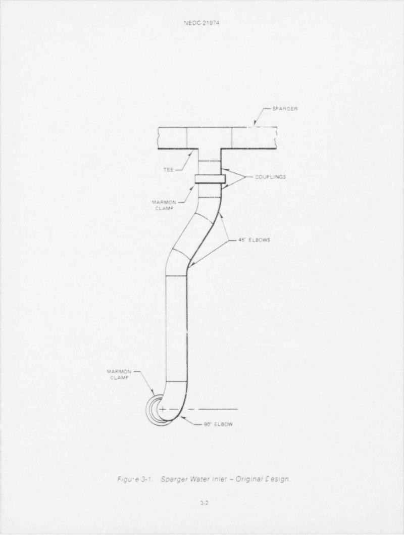
The third change concerns the sparger water inlet. The onginct sparger has a singlewater inlet througn a 2 inch tee. See Figure 31. Welced to tne tee is a 2 Nn long 2 iacnpipe ccuphng. The coucling is provided with a flanged end designed to mate with asecond couphng. The two couphngs are held togetner w!!n a Marmon clamp. This jointcesign has been changed for the following reasons:
(al nemote reinstallation of the Marmon clamp is not con;idered feasible.
(b) The onginalinstallation cf the ~ connector . a senes of pices and elbows joiningthe sparger inlet to the core spray Sparger thermal sleeve. was a field fitupoperation. As a result of the initial field fitup operation the true dimensions of theconnector are unknown. therefore, an icentical replacement connector cannot bepref abncateo.
(c) Ref erring to Figure 3-1. it can ce seen that the old cesign requires that the f aces ofthe flanges on eitner end of the connector be parallel with their mating fianges itis not expected that this condition could be duplicated during a remo, assemblycoeration.
31
N E D C-21974
SP ARGER
._ Y . . ,-
\
\
TEE
| - COUPLINGS
/
YARMCNCLAMP
s
\45 E LBOWS
VARMCN ~CLAMP
\
4_ _._
w
90' E LBCW
Figu e 3-1 Sparger Wa:er inlet - Original C es:gn.
3-2
N E DC-21974
For the reasons outhned above the connector design has been changed. Figure 3-2shows schemaiiCally the essential features of the new design. Ine ball joint provices awater tignt;oint at the sparger inlet and provices a joint which need not b; parallel withthe sparger. It aiso provides a means of assuring parallelism at the other end Decause byrotating the connector below the ball joint and si'.1ultaneously correctly positioning thethermal sleeve the lower Marmon type flanges can te made 'e parallel. The slip jointprovides a means to adjust the length of the connector. A new heavy duty Marmon typeclamp has been designed to replace the one piece strap type Marmon clamp presentlyused to join the connector coupling to the thermal sleeve coupiing. The new design isneeded Decause remote installation of the one piece clamp is not feasible. The new twopiece design provides relative ease of installation and an increased margin of safety f romstress considerations.
The new connector design has three potentialleak pattu. One is at the ba!-! oint. a secondJ
is at the slip joint and the third is at the thermal sleeve Marmon clamp joint. As stated inthe new performance requirements section. Paragrapn 2.3, the max mum a!!Owable leakrete is 8 gallons per minute.
Tests at General Elec^nc show the following typical ieak rates for the three joints:
Identification Leakage Rate (gpm)
Ball joint 0Slip joint 0.8 maxMarmon joint 0.06 max
TOTAL 0.86 max
Thus the new connector design meets the design requirement.
3.2 New Materials - Sparger
There are no known materials probtems with the existing sparger. Experierce withBoihng Water Reactor components has shown that some heats of Type 304 stainlesssteel are susceptible to Intergranular Stress Corrosion Cracking (IGSCC) in the as-welded condmon. The existing sparger and the connector were fabricated using Type304 austenitic stain |ess steel. Type 316 austenitic stainless steel (having carbon contentlimited to a maximum of 0 02 e) has been used for the new replacement components.TheType 316 material has tne same physical properties as the Type 304 material, however.tests by General Electric have shown that susceptibility to IGSCC is significantly reducedby using Type 316 stainless steel. Thus, the replacement sparger and connector areconsidered to be better oonsidering IGSCC than the existing sparger and connector.
3.3 New Co,ponents - Steam Baffle
The new oaffle has Deen designed tc De a direct replacement unit for the existing baffle.All components have the same configuration except as cescribed below:
The baffle is clamped to the reactor vessel by eight " studs"(GE Drawing No.137C7221).The stud design has Deen slightly changed to accomrnocate remote installation tech-niques. The changes inclu7 a tacered lead-in for wrench locating which lengthens the
33
N E D C-2 ' 974
$P A FA Q ER
/
/r
/<
T I [ w|_ _ __-
9
% AI
I #~' B ALL JCIN T
__ _/
~.
- - ---
/as Ecsoas d /
\
\__
- SLEE'vE__
I
l I
I I
.I I~ - - _
hLAYb m
(+ .- -- 90 etBCA
''g%?& 3-2. SCBf;E! N2?ET IniE: - SE:|2CE' ?ECT OES!yn
34
N E D C-21974
part out dces not affect the working lengtn. and four hcles in the base to provice tiepoints for a stud insertion tool. The toit pre-loac nas teen recucea from 100 ft-Ibs to 55f tats. Tne new pre-! cad produces a loacing whicn is acceotat|e using ASME Section lilDesign Rules. The sparger ring is c!amped to the baffle using eight ''J-bolts '(ReferenceGE Drawing No. 16782245). These J-bolts have also been recesignec to accommodateremote assembly As with the stud cesign, the J-ocit mocification involves adding awrench locating lead-in ano does not affect the working lengtn of the part.
The caffle plate latch modification, incorporated in earlier modifications, nas been
incorporated in the new cesign. The principle of the original modification was retained.The design details were modified because it was convenient to do so and imorovedperformance could be expected.
3.4 New Materials - Steam Baffle
There are no snown matenals problems with the existing baffle. The baffle, like thesparger. has teen designed using ASTM specification Type 316 austenitic stainless steelrather than Type 304 used in the existing baffle.
353-6
* EDC-21974,
4.0 DESIGN VERIFICATION
4.1 The Design Verification Program
Des:gn venficm:en of tre scarger core scray cistncuticn nas teen accomolisnea cy fuilsca!e test;ng Design venfication of the sparger anc caffle structural anc mater:al cnarac-tenstics nas teen acccmplisnea cy stress analysts f see Accencix 2 ) anc incepencentreaew cy cualifiec incecencent rev: ewers.
4.2 The Test Program
The core scray distncution for the new scarger has resulted from a planned senes Oftests There were eignt test senes. The Test Report ( Appendix 3. Section 3) dccumentsthe complete ::escnption of the full scale 'est f acility. The test f acility provicec thecapatility to test a fuH size scarger over a range of sparger operat:ng conditions inc!ud-mg sparger f!cw reactor pressure and a steam environment. Several of the ect!ier testswere concucted in tne laDortery using a cencn type setuo. The lateratory f acilit:es arealso cescnbec :n the test recort
The sec' ions that follow summanze the test Objectives and the test resu|ts Cf the eight testsenes The 'est report is referenced frecuently to cirect the reacer to the location of tnetest cata teing ciscussed. To simphfy ;centification. tne tests herem are numcered ?nesame as :n the test report.
4.2.1 Test B11-1 Sparger Flow Distribution Test
Tne sparger flow cistntution test was performed to demonstrate an essentially equal rateof ficw from eacn of the 36 noz:!es en the sparger. Confirmation of ecuality gaveevicence that there aere no unknown tnermal nydcauhc cnaractenstics assoc:ated withthe sparger ring. The test procecure anc *est acparatus are desentec in Accencix 3.Sage 3.19
The test results are summanzed as f 0Hcws'
Adjustec !cw ficw(303 gprrnHignest ficw 8.99 gpmAverage f!Ow 3.75 gpmLowest flow $ 52 gprn
Maximum ceviat;cn - 2.74c :
- 2. 63 = =
ACjusted htgn ficw(470 gpm;Hegnest f!cw 1415g;mA.erage f!cw 13.72 gpmLowes' flow 13 38 gem
Maximum ceviation - 313*:- 2.46
NE DC-21974
4.2.2 Test 811-2. Single Nozzle Bench Flow Tests
Tne s:ngie nc 2!e cencn flow test Aas performec to cemonstrate an essentially ecual rateof flow from eacn incivicual no: ie to De used in sparger tests. (This test Aas in f actcerformec pncr to the Test B11-1 ) Confirmaticn of this ob;ective aas necessary tocrovice a casis for the evaivation of the flow rate of the ncz:ms Anen usec m tneprevioss|y cescncec Sparger Pcw Distnbution Test.The test croceaure anc test appara-tus are cescncea in Appendix 3. Fage 3-29
Test results are summanzed be ow-
At 25 psig sparger pressure 38 no |es tested)
Higr est flow 71 gpmAverage flow 6 34 gpmLowest flow 6.7 gpm
Maximum ceviation f rom average -3 S c- 2.150
At 42 psig sparger pressure (2 no:2!es tested)
Measured flow = 9 3 gpm
At 65.9 psig sparger pressure i2 nor:les tested)
Measured flow = 11.5 gpm
4.2.3 Test B11-3 Single Noz.!e- Pattern Test
Tne single nozz!e pattern test had two main cojectives. First. it was intenced to cefine t9eeffect of vanc us steam oressure concitions on tne nor:le flow pattern anc second. it was
mtendec tnat the test results tculd show that flow cistncution was not significantlyalterec Oy tre convenient spnerical ball icint eloows which would ce used in futuretesting rather tnan the mitre-cut e!Oows to ce usec cn the new sparger. The test resultscic not com;|etely satisfy the test cbjectives Tne test apoaratus cescnbec in Appencix3. Degmnmg en Page 3.33 concists of the f ull scale test f acility. The cross sectienec areaof the mstrumented water collecting fuel channels were the same as a full size fuelcnannel. Most of 'he flow from one nozzle positioned at sparger neignt above the fuelcnannels was collectec in cnly four channels. The coarseness of the measuring systemresultec in data that dic not adecuately define the flow cattern. The cata did snow thatinere is no obvious cifference il results Ahen testing with either the schencal tall e! bowor the mitre cut elbow. However. it can net be stated that there is no difference Testresu'ts are shown in Appendix 3. beginning on Page 3.34.
Upon evaluating the test cata anc notmg the inconclusive results. it was cecided that thecverah design venf tcation could test be servec by prcceeding with the remaining pre-planned tests This cec:s;on was basec on tnree consicerations: the amount of time
required to mccify the facihty to provide a finer ficw distribution measunng systern. theexpectation nat maividual noz:!e flow cistnbutions woulc ce significantly alterec cy
a2
NE OC 21974
interaction affects cf steam f!ow ano ac;acent no:2!e f!OWS. anO the re5u'!s cf Test 811-4(see f urther ciscussion in Section 4.2 4;
4.2.4 Test 811-4 Single No::le Pattern Test in Air
Test B11-4 was des gnec to measure the flow distrioution from incmcual no :tes Anentested in air. These tests were COncuctec in tre laOoratory curing the time perioc TestB11-3 was temg performec :n the test f acihty.
For the B11-4 tests. tne col |ector system nac a relat:vely f:nc gt:c The conectors were 44 inch squares as compared to the 7 4 7.4 inch squares of the coarse gnd used in TestB11-3.
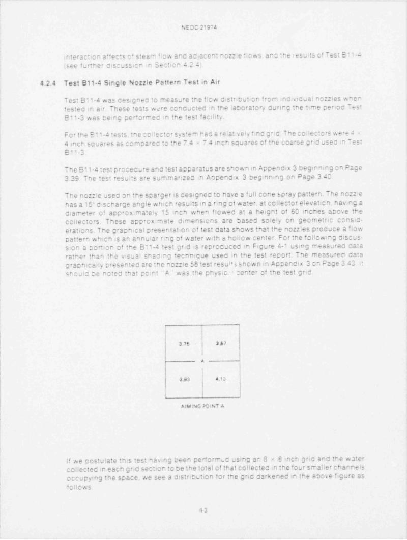
The B11-4 test procecure anc test apparatus are shown in Appencix 3 deginning on Page3 39 Tne test results are summarized in Aapencix 3 teginning on Page 3 40
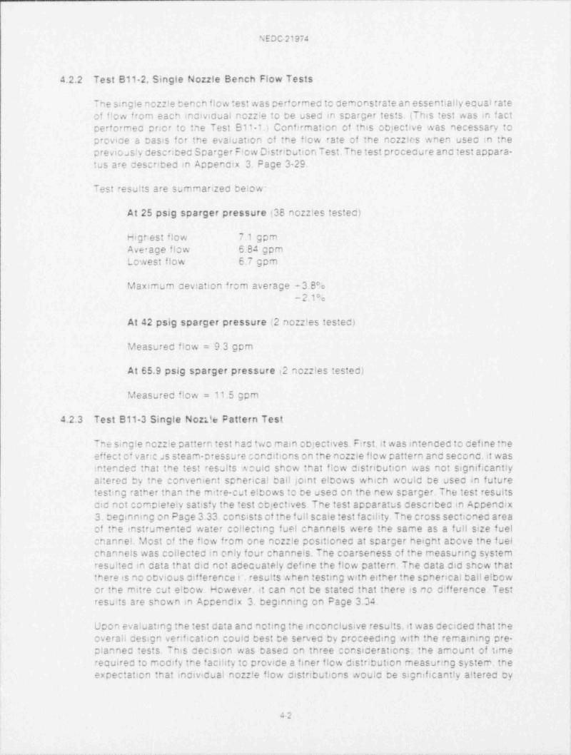
The nor:!e useo on tre scarger is cesigned to have a full cone spray pattern.The no :Iehas a 15; cischarge angle whicn results in a ring of water, at collector etevaticn. hav.ng aciameter of acproximately 15 incn when ficwed at a height of 50 inches above theconectors These approximate cimensions are based solely on gecmetric consic-erations. The grapnical presentation of test data shows that the nor:les produce a flowpattern which is an annuiar nng of water with a hollow center. For the fol!cwing discus-s:on a portion of the B11-4 test gnd is recrocucea in Figure 4-1 using measured catarather than the visual snac:ng tecnnique used in the test report. The measurec catagracnically presentec are the no :le 58 test resul's snown in Appendix 3 cn Page 3 43. Itshoulc ce notea that pom: -A was the physic, center of the test grid.
3 ?s 337
A
3.93 4 13
i
AiVING PcINT A
If we postulate this test having been performud using an 3 8 inch gric and tre watercollected in each grid section to be the total of that collected in the four smaller channelsoccupymg the space, we see a otstricution for the grid carkened in the acove figure asfollows.
43
NE DC 21974
i| i
0 0 O.5 | 0.25 0 25 i 0 |'
8 9 10 11 12 . 13 !'
!',
I i I i'
!: i
I i i i
3.12 15 | 1.12 0 94 | 1.5 0 25i
! i- 16 17 , 18 19 ! 20 21
| | i.;
D-j
i
I { |i
I 0.12 0 88 i 0.25 0.25 ; 0.88 0.25 {l j 4
I, 24 25 26 27 | 28 29' l
A E
!
0 25 1.5 0.31 0.25 i 1.25 OE2!
'
22 23 34 35 ! 36 37 :,
! |'
C.
Ii
O 0 62 1.5 1 44 1.19 0 19'
40 41 42 43 44 45'
)
. |'
1 )
O I O 0.25 0 69 0 0,
{ 48 49 50 ' El 52 53
i
LEGEND.
0.25 - -lNCHES OF W AT[R
26 - -COLLECTION GRID LOCATIONA A4 MING PCtNT
F gure 4-1 Measurea F!cw D:stribution Samcie of Portion of 511-4 Test Grid. Nc::!e 59.
1
N E DC-21974
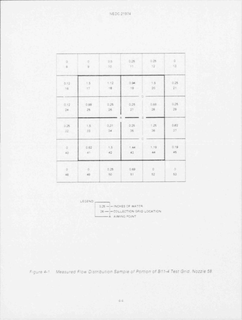
Similar:y. if we acstu: ate that due to some uncefined effect the center of the nc :te flowcattern is cisplaced to peints B 'C'' . o r D". totalhng the f ow within ne carsenec 88 ;ncn gncs crocuces the fcilowing prierns:
li i l
'
|16' 1.62 2 81 2.75
''1.06
i 1 i <<,
f f f I
!
2 37 3.50 2.75 1.06 0 62 3.S8
-
AIMING point B AIMING PotNT C AIMING point o
The Cistnbutions are sinkingly similar to those cotained in Test 511-3 where the largegno (7 4 - 7 4) was used in a steam environment.
4.2.5 Test B11-5 Sparger Ring Development Tests
The purpose of tms test series cas to expenmentally develcp a sparger no le aimingpattern to test reproduce the desired flow districution of the cesign specification. lt wasalso a reOuirement that the resultant pattern De readily reptoducible Cn the new sparger.Cor:sidenng that (1) tne sparger in plan view is octagonal in snape (2) the sparger coesnot lie in one plane but has in f act. a 19 cegree bend f rom the horizontal plane. and (3) thenozz'es are not uniformly spaced around the sparger. it was expected that the nor !eelbows would te space onentec in three dimensions. Further. considenng that a onecegree rotation of the no: le results in a displacement of the flow pattern center ofapproximately one inch at the intersect point on the core surface. it was cecidea thatnoz !e aiming would De best achieved by projecting a hght beam from the nor:le to atarget piaced on tne core surface rather tnan trying to measure angles in tnree cimen-sions The !ignt team trave!s a patn that is the crojection of the no :le flow axis.Exper;ence with this technique nas snown that the nozzle aiming (light bearr intersectpoint) .s reproducicle witnin a arcte having a diameter of one inch er less.
The test facihties for test 811-5 are descnced in Appendix 3. Section 3.7. The test
crocecures are containec in Appencix 3. beginning on Page 3.45.
Tne test results are given in Accendix 3. teg1nning on Page 3.48. Figure 3.72. " aimingpattern No.1 Refernna to aimmg pattern No.1 it can be seen that the aiming pointswere cesenbed in tacular form. and also by diagram. The x" locations show theintencec intersect ocint f or the hght ceam.The numbers around and just inside ihe circlerepresent the az:rnutnallocation of the no les. It might te noted that the sparger has anaxis of geomeinc symmetry about the 0-160' axis. (0 is shown in the lower left corner.)Itcan also te seen that the aiming point pattern is generally symmetrical about the spargeraxis cf symmetry When a test run was comp!etea the test results were made availacle intne form shown in Page 3 49 of the test report. In these presentations the sparger O'pos:t:en :s always at the lower lef t ocsition Looking at Figure 3.73 on Page 3.49 we see
s
N E DC 21974
meacurec channe! f ca for 31 of ine 34 active cnannels in the core. At : east two channelshac macecuate fiow ishown as zero). Figure 3 7.5 on Page 3 51 snows aiming pattern1A For this test a tota! cf erght noccies were reaimec to provide flow to the ceficient
t.nanne!s Pesults of nis enange are s* wn in Figure 3.7 6 en Page 3 52. Flow to theceficient cnannels aas improved 3ut still cid not meet the cesign gcal Also it can ce seenthat :nis resultec in one cnannel near !ne core center now navmg a measured flow of lessthan ine ces' rec 2 gpm
Tne test-asaluate-reaim cycle aas continued until a pattern acDreaching the CDtimumflow cistr:Oution for the water available was Octainec, at whicn time test series 811-7.Core Cochng Configuration Test. sas begun. The results of inis test series is discussec inSection a 2.7 et this report.
4.2.6 Test B11-6, Sparger Dimensional Check
Tes 511-6 was concucted pncr to beginning Test 511-5. In performing Test B11-6 anumter of precise measurements were made te venfy that the test scarger met the GEdrawing dimensional requirements for the new sparger This test was deemed necessarybecause it is niencec that the new sparger be. 50 f ar as is practical, an exact cuplicate ofthe fmal test scarger configuration. Duplicate spargers should have cuplicate flowcistncution cnaractenstics.
The test recuirements and test crocedure are given in Appencix 3 on Page 3 63. Themeasurements taken are given in Appendix 4
initial measurements showed that tne sparger cic not conform to the crawing recuire-ments Tne sparger was rewcrked as requirec.The reported c;mensions were taken af ter+he reworx and are substantially identical to crawmg recuirements.
4.2.7 Test B11-7 Core Cooling Confirmation Test
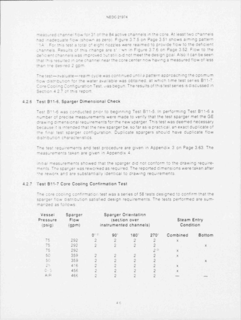
Tne core ccchng confirmation test was a senes of 58 tests cesignec to confirm tnat thescarger f|cw cistribution satisfied cesign repuirements. The tests performed are sum-marizec as felicws:
Vessel Sparger Sparger OrientationPressure Flow (section over Steam Entry
(psig) (gpm) instrumented channels) Condition
0= ; 90: 180: 270= Combined Bottom75 292 2 2 2 2 x
75 292 2 2 2 2 x
75 292 23 x
50 259 2 2 2 2 x
50 359 2 2 2 2 x
25 415 2 2 2 2 x
C- 5 455 2 2 2 2 x
AiA 455 2 2 2 2 - -
4C
NEDC 21974
NOTE:
- A m; ca::ern m s Accen x 3 c ge 3 ma
mm ng ca::en F ;;;erax 3 Pace 3 65>m
;3i anng pa::ern 'G Arpenca 3 Page 3 59)
Aiming pattern '1 I was used for 2 test :uns in one azimuthal position. Because theresults Were not considered sufficient in quantity to provide a basis for conclusion. theyare not ncludec in the fcilowing discussions.
Aiming patterns '1F'' and '1 H ' used for a total of 56 test runs. are considered to beequivalent based on test resuits. A small change was made in the location of aimingpoints 5. B,14 and 17 to provide physical symmetry about the sparger axis of symmetry.The aiming coints of nozz!es 8 and 14 were adjusted 0.37 inches. for nozz!es 5 and 17aiming points were acjusted 1.85 inches.
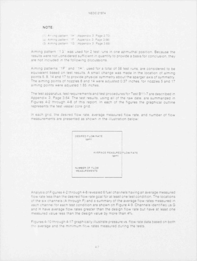
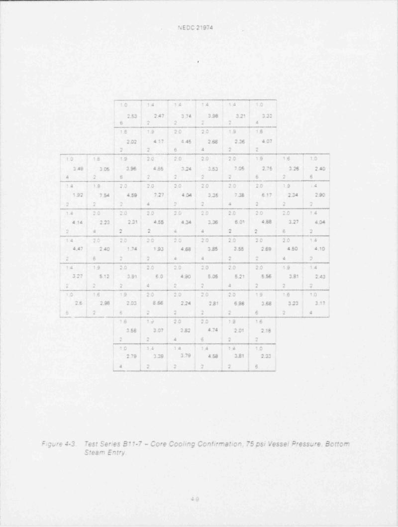
The test apparatus. test requirements and test procedures f or Test B11-7 are described inAppendix 3. Page 3.54 The test results. using all of the raw date. are summarized inFigures 4-2 througn 4-8 of inis report. In each of the figures the graphical outlinerepresents the test vessel core grid.
|n each grid. the desired flow rate, average measured flow rate, ano number of flowmeasurements are presented as shown in the illustration below:
CESIRED F low R ATE4;pm)
AVEP AGE YEASuPED$ LOW R ATE(gp H
NUMBER OF CLCWV E ASLF EY E NTS
Analysis of Figures 4-2 through 4-8 revealed 6 fuel charinels having an average measuredflow rate less than the desired ficw rate goal for at least one test condition. The locationsof the six channels ( A througn F) and a summary of the average flow rates measured ineacn channel for eacn test condition are shown on Figure 4 9 Channels identifiec as Gand H have average flow rates greater than the design flow rate but nave at least onemeasured value tess than the design value by more than 4 e.
Figures 4-10 througn 4-17 graphically illustrate pressure vs. ficw rate cata cased On bothaverage anc the minimum flow rates measured during the tests.*m
.: . -
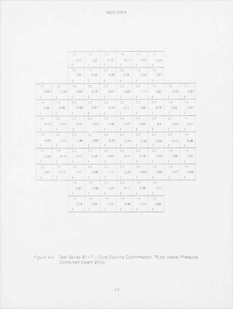
N E DC-21974
.,a a : a 2
-
2 71 2.6 3.72 4.17 3.52 3.22; , . , ,. . . . . a
.,, .a.
, < . ,, -
i.... .. ... .
1 92 4.28 4 05 2.25 2.33 3 67
,
. o 4 ., ,
., -
.
20 .' .0 20 19 16 10'O i 16 19 20 i
2 06 2.75 0.E 9 5.16 , 2.47 2.92 7.11' 2.63 3.03 2.61 :
. . . . t t-
4, - , , , , - ,
u-
4 4 7 .a,
a, e n ,, e , ,, ,, ,- 4. . .. . . .. .. ,a
2 08 6.95 4 58 6 E7 4.19 3.13 7.59 6.75 2.52 2 47
.- 4 , , , , ,
. i ., . . . . .
, *.. . . -
, ., , ,, ,c; .
,- ,,
. s .. . u . v . n. . . 2, , ,
4 13 2 41 2.41 4 52 3 09 2.37 5.60 4.4 3.02 4.0 '7
2 a 2 4 4 2 2 6 2
.,3-, , n. ,,3 s .
,, , ,3 ..n.,,,.. . .a . tu . ,
4 45 : 2.13 1.96 , 2.69 t 4:5' 3.14 2.7s : 2.54 4 13 4.06i , , ,
a > . . 4 4 . . 4 ., - , ,
, 4 4 a ,, ,, -, , n. - a . ,n , a. ,4. .. .. ... 6 . ,,
|.a
,
3.06 - 4.' 4 4 13 5 30 4 47 4 77 5.75 ' 4.55 0.56 2.%
., - -
-. .
" . .. , , ,
. - . . .
a ' 6 i9 2^ 20 20 20 19 !6 1.0!
2 S1 3.10 1.77 8 09 ? 77 2.2 S 6.82 3 30 0.07 . 3.54i
,. . .a ., - - ,
.- .- 4 ,, - ,. . .
,
..: , . , r
. .s .a a. . . ,.
3.47 2.68 3.20 4.13 2 08 2.i 7., ,.
. ., a v, ,. .
10 : 4 14 ;4 14 10,
. I
2.74 150 0 70 4 46 0.73 ', 2.65i , ! -, , , ,
. . . ; . t D
F: Cure A-2 Test Series S117 - Core CCCI:ng Confirmat Cn. 75 si Vessel Pressure.n -
V .# w( f i .
43
u s w sa'-LM c;,/ ncnr . e-
0
14 14 : 4 1 4 | 0| - '
2.53 2 47 3 74 3.95 3.21 0.30,
c, ,..
.- . 3. .
' 9 20 20 19 tS15
2.02 4 17 4 45 2.68 2.36 4 07, , - 4 .,. . e .
33 ., c. 3a ., e n e n .e n. , n. ,c ,
s 1.s. . v . a
3 49 3 05 3.96 435 3;4 3.53 7.05 2.75 3 26 2 40. -
a . . ., --
~ ., o, . , ,
o a :
,a ,a ,, ,, e.. .. .w . n , n .0 ,n ,3 - ~
, ,
. a .s ,.
1.92 7.54 4.59 7.27 4 04 3.25 7.38 E 17 2.04 2.90, - , ., ,,. 4 > .- 4 4 .
. - ,a .- c .na ..,- , .- . -,a . - , ..
,,,
, . , - ,.a s .w
4 14 223 2.31 4.55 4.34 3.36 6.01 4.88 3.27 4.04
: 4 2 2 e 4 2 2 6 2
,4 - . .- ..,, ...s; 2 . . n, . , -, , ,,, , , . .. .. .
4.47 2 40 1.74 1.93 , 4.68 325 3.55 2.69 4.50 ! 4.10i
i
.- o, - a -
, ,- , .,- ,
. ...
.. . ,
. , - . 3 .a . - -a .-. . , - 0 .., .., 1 e-, , s .
, ,4 -> .
3 27 5.12 3 91 E .0 4.90 5.05 5.21 ' 5.56 3.31 2.43, , , ,- , ,
.. ,
. . . . . 4 . . 4
.. :. 3a ,, ,, ,, ,,l a. c , ,
. .. .. . .s .
21 2.98 2.03 5 66 2.24 221 638 3.68 323 3.17- ! ,
s ., . , -t . -- , .
. . . .;
?6 1s 20 20 19 15
a so a s7 . 5,,4 4 ,> 4 , n1 ,1 a,c, ,e ,- . . . . . .
.- ., 4- , ,s . .
IO | 14 14 1.4 14 t;,
i
,s .eg 3.7 a a =s- 3.e1 [ ,3..,., , -.,a - -. - , . . .
t
4 i , , - , - I g.. i . . e ,
?;gure 4-3. Test Series B11-7 - Core Cccling Ccnfirmation. 75 psi Vessel Pressure. Scticmc *o = em :.e r r ,.r isi-s w
.e--
g em etq =e a% b s'- 6 rN8O
.,: ; Ia 4 4 : 2
...s *al 4 y- e 3. 3 .. _ 4 ~,s, n , -- , :,- s v
,, . ., . 4. .
p { h 9 v <) % h.a
O '' " '
es
6 - .' f 0% Q
R .v% *% C''>.@ *- ''% [q 4 sc.s24
me
e s s.~<
.,-
*e %,
D * *
-#
p
e. ".P
* M M.% Fs
9 A * O I ' [. +
. . . . - . . .
* s . g. . .o b g.a 9.O D, s ..h9 (* 9s.449 $,.,. a^ c- s y18 9O $ r .a ,
q A
sw
4 .y *
.% . .;-
. n.* a
,., 4
4
, %
A w . . . * a ssa
I *. f eg $* m
e.,s *
r..4** a s. m
7 , **w
-.c a, aej cD+0 2 acw s em * mm -
m ..a 34.e -sD 4 ..s .a .a .w e 4w ,3 M .. s . . . e s
. m . . & .- e.+ m . . . . *
a
4 b . b' .m= = r ,
. .
m. M 6% == m , - e e. n m .,
W . W & .d 4 W
O E*< ~. . -s.I. .s .E.,,J~ . ., .
4 . g 4 a. .a .
a
.-, = a
.s . e a w 9 es i **,
. w .- .- * w M.m
$. ed* * * 9 ,
, #* * * * 9 F.
. . .. S 536 4 56 4 06 3 AD 4 32 4 63
,s
, ,*
.
.-- , -
- .
. & . 6 N
. M. - . ,
I-4 .- -.
, ,4.d m,
%d.' - i ga -
.
. b w s b . 4
J-,4 c . .y c.. .; -- t. .7 7 e a t. 6 ? K. E Sc'; 4 . ,' 6 * "
s . 3, . 8
.- .g .- . 4
,~ ,
.., .
s= | e
. s .e9 - * , == **A 9 - - -
% ras s e . s w
4 .r M* s s -.299 * * *
9.m.e g4-.Oj . .. e . n .9 80 g gyq 3.369 ,
- ' * *
.. a d..ss
.s .: - - -
.- : , 4-
. 6 . *
,- .- . .
g . ;* +.,
. a *OW * O
4 ew gg 9 O(..4 .h C.4*
%'''4,,_,g J -- w,
, . .
. * O .
'
| 4 ' 4 ' a a 1 ^'
2.E 4 54 4 33 5 08 E34 2.'E
* . . ., - -. ,
6
i . .R. . e me 's v* .! { ev v u g j .O O --O '? O.$ .f O. . , w' f u .$ | 5 .$ $ ,Y .*$ { .V O. .#^
a f &. e . &. .C * . c* F &*,'* *.,
4,, OMbR. -
.e.,-,8vv - 4i P,M, -... .< - t.F',i'.% y
se - r.*
NEDC 21974
?4 14 14 10 |; 14 ; . ,
,
! 2.E 7 j 3291.63 3 45 4 54 | 4 44
6 2 2 2 2 ! 4,
16 19 i 20 | 20 19 15 i
! , i i ,'4 07 . 4.12 5.14 j 3 49 2.26 4.70; i
| ! t !
2 - 2 6 4 f 2 1 2: 0 | 16 19 20 [ 20 | 20 20 1.9 i 16 | 10 ii i
,
!| !'
4 16 2.66 4.93 5.95 . 3.66 i 4.57 ; B.07 3.12 3.54 2.50j
,'
16
'
2 2 2 6 2 i 64 2 6 2 +
14 19 20 20 2.0 20 | 20 | 20 14i,
6 I i NO1 50 B 88 6.17 9 46 4 19 4 76 ; 8.77 | 7.28 OATA 3.55,'
ii ,
2 2 2 4 2 i 2 4 2'
i. .
2 !, i
14 '14 20 20 2.0,
2.0 20 | 20 20 2.0 ;,
| | |' '
4 19 2.29 233 1 5 43 * 6..' 7 5.08 7 45 6.22 4 19 5.12i -
j|4 i1
| 4 2 2 6 22 4* * '
20 I 20 | 2.0 2 .0 | 20 , 20 l 14 '14 22 20 + ,
i | | '|{5.34 2.57 2.41 2.45 j 6 20 6.01 . 5.03 3.51 6.06 4 60li
2 6 2 !2 |4 |4 | 2 2 ! 4 | 214 : 9 20 20 ! 20 i 20 20 8 20 19 14 -i
> ,
I!' i ,,
f ! j|
t i
327 6.50 | 5 92 | 7.00 } 5 40 5 45 6 17 7.56 i 3.89 2.61 ,
2 2 2 4 ! 2 | 2 4 2 2 2 |'
i '
!' 2 0 |2.0
| | !1 0 , ;E i9 2.0 1 2.0 19 # 16
|1.0
i
2 61 ', 3 08 i 2.58 | 9.15 2.92 ! 3.27 i 8.25 c 41 ! 4.08 3 74; ii I , j
'
5 2 6 | 2 2 2 i 2 ! 6 2 4'j,
! !6 j :9 20 t 20 ! 19 1 16 i
4 4C I 3 56 4.90 5.52 2.40 3.29I
i
2 !2 '4 E 2 2, ,
d | 4 14 | 14 I 14 10 !*O ,
| ! 5 49 ! 5.26 2.18t i
- 2 50 | 4.02 | 4 20 j
|2l | ! ''4 2 2 { 2 6i;
: gL;'e .1-5. Test Se%es B17-7 - Care Cco!;ng Confirmation. 50 pst Vesse! P"essurc EvuamSteam Entry.
a1
N E DC-21974
i $ 0 1. 14 . 14 i 14 | 10'
t'
2.79 335 . 410 . 4.88 421 3.88;! ! !'
6 2 2 ! 2 2 '4'
20 19 i 161 16 19 20 i
'3.58 6.57 . 5.48 4.12 3 65 5.C3
|i ! ,
6 ! 4 2 {2' 2 2 '
-
|10 | 15 j 1.9 20 2.0 20 23 19 | 1.6 1 1.0'
I,
1
5.04 2.59 1 4 30 6.26 3.05 4.02 8.77 { 3.55 j 3 t,6 | 2.69'
,
I4 2 6 2 2 2 2 | 5 2 6'
8 1414 Is 20 i 20 20 20 20 1 20 1.9j j
r' '2 42 ; 11.38 6.48 10.92 4.72 54*i 9.41 8.09 2.51 3 44
, ,
|
2 2 2 4 0 2 4 1 2 2 2< , ,
20 20 2.0 20 | 20 20 ! 14: 4 ! 20 1 20 +
14,67 ; 5.34 i 4 73 7.76 6 43 4.76 4 864.22 3 44 4.11 '
{ I
2 i 4 1 2 i 2 4 ; 4 2 2 6 2' *,
14 j 20 20 20 20 20 20 i 2 .0 20 14,
i. >
5 31 3 D' "' 98 2.53 i 5 60 1 5.99 5.07 2 10 5.60 5 25, ,
I I! |'
6 2 2 3 4 4 2 2 4 22 4 i4
'14 ! 19 - 20 20 i 20 - 20 2.0 20 i 19 14I t ! !
,
.
4.16 | 8 04 6 48 911 ! 4 .6 ' ' 97 7 54 6.79 4 15 3 09' !
i I '
2 i: 2 a 2 2 * 4 2 2*
1 16 19 20 2 .0 4 20 2.0 '9 | 16 1.03
, t i'
3 17 B 01 4.77 5.39 3.78'
3.14 | 3.25 i 3.00 S.00' ' 3.00 1! i !
2 ' 6 2 4 |6 i 2 6 2 2 2' '
16 19 ' 20 20 19 j 16i 1' '
5 48 4 91 4.7B 5.50 716 4 47'
2 2 4 6 2 2
14 14 10to 14 14 ,,
i I
e 2 !2'
5.25 , 5.13 2.333 16 5 00 of3 |i
i! 2 | 2 s'
Frgute 4-6. Test Series E11-7 - Core Cochng Confirmation. 25 pst Vessel Pressure.Combined Steam Entry.
.: .1.'
-
J. ;
L M4-
..r
.
. NEDC 21974.[,.
.i a
p J
,if $: 4 t,
. --
3-
?, - ,
- , -
i , ji , V? t 9
1|{ Th i
|
_ f10 | 14 14 14 14 ;1D'
5 ',
!. 1.87 4.31 ' 4.90 3 45 + 5 66 2.75 l'
]" i li ; ,
?g 6 2 i 2 2 2 4 :i 1
-
| 16 19 j 20 2.0 19 i6',
,, 1 1- '
l 3.67 4.77 I 724 5.51 6 36 323 g'
i
2 2 6 4 2 2 ;
i i i-
-f'~
'. 20 2 .0 20 19 16 10 .
'10 j 1E 19 20 i
?;I 4.06 t 4 29 5 11 5 55 | 4.91 3.56 7.61 4.98 2.57 2.62 -
.
| -
4 4 2 6 2 2 2 2 6 2 6:j g j, i
'- t 14 t 19 20 20 2.0 2.0 20 20 19 141 , -
h | | |*
'
' %* 7.70 3.99 7.44, 721 4.57 4.43 7.43 7 78 728 4.89 iE
|-. s,
| 2 i 4 i 2 2 4 ! 2 2 2_
2 2' < =
14 20 . 20 20 2.0 20 20 2. 2.0 14,
3.13 5 67 3.04 4.77 7 64 9.04 5 97 f 5 57 5 37 t 7.62
( 2 4 2 f 2 4 4 2 f2 6 2 -.
'
! 14 2.0 , 20 ' 2 .0 20 20 2.0 20 i 20 [ 14',
l (.
! , 1i
i 5 7E I 6 47 4.09 i 4.47 5.91 ! 7 .2 . i 3.94 3.52 5.66 ! 437 -'
| f !'
j 2 6 2 2 ! 4 4 2 2 4 ! 2 -
'r
14 | 1.9 . 20 00 2C | 2.0 i 2.0 20 19 i i4-
' ! -'
5 49 ; 4 43 7.20 E 66 3.49 5 19 | 8 48 7.50 t 6 33 5.90'
f2 {2 2 4 i 2 2 22 2 4r,
>. 16 10 20 ' 2.0 2.0 20 19 16 | 10 j _[1.0 ,
I '
r .j i
. j 3.E5 5.68 6.16 | B.7 B | 2.40 4.02 | 5.91 4 51 , 5.17 i 3.65 i J,
|4 -2 i 2 | 2 !2 6 2'
. I 6 2 6 I' '
-
i 6 . :9 20 20 19 6'
.
: n I'
1 ! 4.72 E.30 4.13 5.77 E.90 4.34 {'
2 2 i4 6 2 2 ,.
s; 10
_ f-{' 10 | 14 | 14 14 ' 4,
|'-
325 4.59 ! 5 15 3.71 4.03 2.77 1r
-;
|4 2 |2 ! 2 |2 !6 }:
-s ,'n -
r ,f
. p
ia
, .! .ha
l *E'
2-
f!;Ure 67. TEST Series B11-7 - Core Ccoting Confirmation, O psi Vessel Pressure Comcinedi Steam Entry.
-
-
i1
-
4r
$<= -
,
t .. m-
4 13j
5
E
.. _ , . , . . ., ,,. .i ..m-i--isim --i-.mi,.--is--e.---s---i---imm--.=-----------mum----m-summe-mmm--munes-em---mm-mummen-ammmmmmum-mmmm-mm-
N E DC-21974
i I
- 10 j 14 14 14 14 'Oj,
I
0.93 ; 3.14 3.30 3.05 3.50 1.29|
< ,
2 ' 2 2 45 2 'i
| 16 19 i 2.0 , 20 19 16i
| 2.67 4.68 | 3.65 I 5.22 4.28 3 68;
I I t''
2 2 6 4 2 2
19 2O 20 20 20 19 15 i 10 !12 | 16 }' i,,
[1 26 3.84 i 4.97 4.1 B { 2.59 3.75 5 45 5.31 2.86 1.26 ;
'
!4 ' 2 !6 2 2 2 2 4 6 2 6
: 4 1.9 20 20 20 20 20 2.0 19 14|
2 69 4 06 4.25 7 's 4 2S0 2 61 7.17 i 6.08 316 4.01
I2 2 2 4 2 2 4 i2 2 2 ,
t4 20 | 20 2.0 20 20 20 20 2.0 14 '
;
| 3 50 4 01 ! 3.52 ' 4.17 4.53| r .
| 3.97 6.94 i 3.571.; 8 4.11, i
? 4 '2 2 1 4 ' 4 I 2 !2 6 2' '
14 22 20 20 2.0 20 20 20 2.0 '4,
i .
! 5.19 ; 4.' 2 i 4.67 4.07 4.30 4.92 4 51 3.00 4.31 ! 3.92,
| t i
2 6 2 2 4 4 2 2 4 2'
,
6 i
, 20 j 20 t9 j ,20 20 20 1414 } 19 20 i
i t
|i 4 36 i 5 83 5 72 . 6.15 332 3.55 6.76 | 4.03 225 4.01 |
';
' I2 2 2 4 2 2 i a ! 2 2 .
' '
10 j 1E 19 20 . 2.0 ! 20 2C I 19 i6 10.
I |'
1.52 | 3.57 6 09 5.88 ' 4.32 4.00 5.17 4.45 4 66 2.16'
!'6 . 6 2 2 2 2 i6 2 ,4
16 1I 20 20 1.9 16t : i
'4.05 5 92 ; 3.60 5 04 5.58 l 3 81
2 I 2 4 6 2 2,
14 14 14 10'O | 14 jj i
f 2.97.
1.74 2.67 ! 3 57 3.28 | 1.33'
1
|2 |2 |2 |6| 34 2i
F gure 4-B. Test Senes B1 -7 - Core Cooling Confirmation. Atmcscneric Air.
s .1.:
N E DC-21974
.
- I
!i E i |i i ;
I i
i i i i l'
'+ < i ; i iI
i
: !
:
I ii
,
i
|r , ,
i ! ii
| | ! ! i !I i ! ! ! I i i
.-
I I | |r |! t i
i-
:i 1,
i l! !
I j : j i !,
! : |'
; a 3 i
t .
|| 1 i .' <
',
-
,,
! i j ,
|',
: 'i4
u A =| j,
,,
j l .
i I.. I 1 I
! | i , i i I,
|; I | i ',
, ,
i | { i, i , i ,
-
| |
i - | i i
I I. I.
| |- o i.
i . ,,
I.
I i
, ,,
l I<
i ! If !
i.,
I,et
, i
l I
:- m Et rtee: ::sTnieu w s v r,
c ' L N *. E . F'P E SSL R E rs : AN D ETE A'J E'.T R Y CON;iG A AT:C't
sc 7ee sac 5:e :sc aec as :. E s: e N,, 1 96 1 74 2 46 2 41 2 9E a 09 4 67 20E : E9 | 93 1 EE 2 45 2 53 4 47 4 07 20C 17- 20 2.28 2 58 3 00 6 'S 6 39 19
2:4 : 9e : 92 s aa 2 4a 4 :: 23a '-
c , , , , , , , 1 2, , , , , , a,7 - a, ,o. .o .. -. . . .. . . .
r 4 i: 4u 2 52 4 19 4 :: su 1.:e 14
3 2 41 : 23 2 E4 2.29 2 44 5 67 41 20+ : 1., ! 40 2 El 2 17 :E: E 47 41: :3
%.- . , - - 4 . c ,s n b . c - . 3 r ,. .a y .p.3,.-,,.,,e -. oi s .M . . - .iv so <-
e - scT o .c s tav Ern v ;N u
Figure 4-9. Channels Receiving Less Than Design Flow Rate.
- ,=e ,a
N E DC-21974
7 -
CHANNEL A
6 - YE ASLRED F LOW |[ -. A ' E R A G E * - A ( A C N L YQ - AV ER AGE" - COVPINE D STE AV E NTR Y
T OP + E C"TC#)
0 A V ER A GE * - B OTTOM STE AM ENTR Y ONLYg - V Alfr. vi F LO N 's-CWN AT 50 A ND 75 as.4 CNL v i
*SE. ElGUR E 4-9
5 -
|
4
2_.
I; At C ME ASLRED FLOW-Cs-
3
NN
NN -
tDESIAEC FLOW / %
/ - %_'
' %%
"MINIMUM MEASURED E LOW
|
|, _
,
I
I
I
i I | Ig
3 25 50 60 75 100
PA ESSURE fmigi
Figure 4-10. Measured Flow Rates. Cnsanel A.
Lie
NEDC 21974
7
CHANNELB
6 - ME ASLRED FLOW
d - A V ER AGE * - air CNL vQ A V ER AG E * - COVE tN E O ETE Af * EN'R Y
TOP + ECT7 0Vi- A V E R AC E" - ECTTOM STE AM E NTR Y CNLY
A - .lNivLvrLOW SHOWN AT 50 AND 'i 00:w - ONL I*
*SEE FiGL AE 4 9
5 - * THIS PCINT REPRESENTS AVEASUREMENT TH AT isLNCONSISTANT WITH ALLVEASUREMENTS FOR ALLOTHER 7 ESTS.
4 -
Ee
3:0
.. A s G '.4 E A SL R E O F .C a
3 *-~
g Is a1 i
C ESIRED F LOW A '%,- w
*/
V6NIMUM VE ASURE D F LCW -
1
I_
l
I
Ii I | |g
0 25 50 70 75 100
PR E SSU A E :4.ca
F'gure 4-11 MESSureC Flow RB!eS. CnBnnel B.
17
N E DC-21974
7
CHA?vNE C/
6+
MEAELRE D E LOAdy AtERAGE*-AiRONLVO - A V ER A GE * - CC'/B:NE O ST E AM ENTR Y
'T OP + E DTTOM,
C - AV ER AGE * - BOTTOM STE Av ENTR Y ONL vA - MINIMUM F LOW (SHOWN AT 50 AND 75 ps,q ONLY)
*EE E F IGUR E 4-9
5 4
4-
-
2%=s0-
-
3 -
A v G 'zE ASUR E D F LOW
\ n
NN n
2 - DESIR ED F LOW h "
N ON
VINIMLM VE ASUR EO F LCW N% -̂
1 -
1 I i
3 25 50 75 700
PR E SSL,R E Wsm:
Figure J-7 2. Measurea Flow Rates. Channel C
4.:5
NEDC 21974
7
CHANNEL D
6 VE AsumED Low-. e cER AGE * _ air Or,L v
O AvEF AGE - c veined sTE Av EsTay.T OP - E C TT Dr/,
- A V EP AG E' - ECTTOM ST Et.'A E NT A v ON Lvg - min 1MLM E LOW SsOnN AT 50 AND 75 m ;; C*,Lv i
(I sEE riGuaE Aa
5 -
t
}aw-
=?::4
3Ose
AV G V E ASL ; E D F LL.'
Q3 m_. * '
\' N
d 9DESIR ED F LOW / N,
4 8 4
14l 91NIMLM VE ASUR ED F LOW w
I
i1 - |
1
|
|
|i ! |3
3 25 50 68 75 1 00
DA ESSUP E ipugi
?!gure 4-13. Measurec !cw Rates. Chanrel D.
.: . c
N E D C-21974
?
CHANNE L E
6- ME AEURE D F LOW
d a w EP AGE' - air ONtsC - A V E R A G E " - COMS:N E D STE AV E NTR Y
' TOP + ECTTOYiO - av ER^cE - BOTTeu STe Av ENTR v cNovg - VWNLMrLOW 'SCWN AT 50 AND 75 asq CN L v i
*S E E F IG U R E t. ?
5-
L4
I_
2L
5E:.
.
3 -
av VE ASLRED c;CW,
I
I
6:y
DESIRED FLOW9'
#
i ! lg
3 25 50 75 '00
pa rSSURE foua)
F;gure 4-74 Measurec' Flow Rates. Cnenne! E.
23
NEDC 21974
7Ii
:IIi
!
C H A fi N E L E
6- ME ASLRED F LOW
d - AkEAAGE*-AiPCNLf; O A' ER t.C E * - COYBtN E D STE AN1 E NTR Y
<?OP+ BC.M OVt O - M E R A C E' - 50TTCV ST EM/ E NT A v ONLv
A - Y tN:f.wr,' r L Cw :ssCW N AT 50 A N D 7 5 psg C *,L v j*SE E F IGLR E a-9j
| !
5-
1
r n
4 -g Av0'AEastpECFLCe.
; |.-i= ,
':-%f
d
-
)i
3~
,i
. -
C w
DEstRED FLCW
i1 -
>
|
!i
I 'fg
D 25 50 75 100
PRESSURE :mmi
-.
r ig u re ~,~ ,a 5. Measurea iow mates. pnenne., r.r v
4 :1
NEDC 21974
I
.
II
l
| CHANNEL G
l6- | ME ASURED F LOW
IC
AV ER ACE * - CO*/BiNED STE AM ENTRYA VER AGE * - AIR ONL v-
Q.'T OP + B O TT O*/ l
O - AV ER A GE * - BOTTOM STE AM ENTR Y CNLYA - VINIMLM r LOA 15HCWN AT EO AND 75 s a CNLY a
| *SEE riGURE 4 9|
5--
$4-
-
?-
Oi
! t
: |- |
N w I\ '|
i
3~{ \
I! g| Av 3 '/ E aSL A E D P LOWj g
,
i \ ,
\6s& ~.,
^
DESIRED F LOW I' % %
| 4!
!,,N . ..Em= E 0 F co
I;'
I
I
! |1-I II
*
'
I
! l! !,
i li ! ! l,
00 25 50 57 75 100
PR E SSUR E tosig)
Figu re 4- 7 6. Measurea Flow Rates. Channel G.
4 22
NEDC-21974
7
|i
CHANNELHt
t
| !
I ME ASLPED F LOA6 I
6 - A V ER AGE * - A( A CNL *| O A s ER AGE' - COV61NED STE AM E NTPV
'
I | iTOP + ECTT C AU
I O - A V E R AGE * - ECTTOM STE AM E NTA Y Of LY4
|| 3 - MINIMUM F LOW SHCwN AT EC AND 75 usq CNLY)
*SE E FIGLR E 4 9iI
5h -
h4 -
? "
$.\>
5 \\*
;
3| \N-
MINIMUM ME ASURED F LCW O
AVG ME ASLFED F LCW
w ONi \| N Os_.
DESIRED F LOW f %1 w
I'
I
.I
t
! I
'r Ii
; II i.r
I 3
II l | I
O
O 25 50 68 75 100
PP ESLURE (:mg)
figur? J-1I ME'BSUfeC fiOW RBIES. Channel H.
123
|.
4.2.8 Test 811-8 Sparger Ring Sensitivity Tests j_
The sparger ong sensitivity tests were performea to obtain data to assess the sensitivity aof core spray cistncution to small effects sucn as sparger manufacturing tolerances. ]neal!ation fituo, nng ce-centenng, and errors in nozzle aimmg A tota! of 22 tests were gperf t *mec inciucmg two control tests tnat were repeats of normai tests performed dcur ng 'ne confirmation test senes B11-7 Each incividual test introcuced a cond tion to ]produce a greater error than can be reahzed dunng sparger installation. Fur example the jsparger cannot ce positioned off center in the reactor ves' el oy more inan 14 incn =
tecause the raffle has a 14 incn nominal c|earance to the vessel wall, nowever for twe of _
the sensitivity tests the sparger was positioned 12 incn off center. _
Test conditions are hsted on Tabie 4-1. A cescriction of the ec;uipment and f aciiiced is -
given in Apoencix 3 on Page 3 76.
Test results are c;iven in Appencix 3 on Pages 3.78 tnrough 3.99-
The results of Tes 31 through 16 conf rm that the sparger spray cistnoutton wa',vmually'
unaffectec.Tnis re; att was expected because the net effect of the test conditio is did notalter the core spray t 'stricution pattern but only displaced the pattern relative ta the core. gFor Tests 17 ana 1F (wo rozz!es were intentionally misaligned relative to aiming pattern1H The aiming gwnt for norte 8 was displaced 1.85 inches away from tne core control -
'
;ocation. The aimmg point for nozz e numcer ' was displaceo 518 inches toward tnengnt nanc edge of the channel containing its onginal aiming point.The tests resulted in ashgnt cegracation of tne core spray distribution for both the steam and air tests. As aresult of this finding the aiming point tolerance for all nozzles on the new sparger will be
-
-
hmitec to 12 mch. Tests 19 and 20. which removed and replaced all nozz!es at random.croduceo results that show core spray distnoution is affected by Ine innerent ;nonuniformity of the flow pattern of the individual nozzles as was observed during Tests
"
.
B11-3 anc B11-4. It is this nonuniformity that is believed to result in the asymmetnc core-
spray cis:r.bution. although the sparger has m;rror symmetry."
It is conc!uced that the new sparger can be expected to have a core spray distnbution -
very close to that of the test soarger inclusive of considenng manufactunng and installa- =
tion tolerances. It is planned trat nozzles for the new sparger be installed on the test |sparger for a fmal confirmati.an test senes. Tests will be performed to cetermine if the e
nonuniformity observed fcr Tests 19 and 20 of the B11-8 sensitivity test exists for the -
prccuctico nozz!es. If these tests incicate that this nonuniformity coes exist for the 3
procuction nozz!es. the testec nozzles from an acceptable core scray distnoution w'il ce icteaned and mstallec on the new sparger in a tocation identical to their !ucation on thetest sparger If the testing moicates that the nonuniformity does not exist for the procuc-tien nozz!es, tne nozz es will ce install d on the production sparger in a rancom cattern. j
i
N'
,
5_
J
95
*
i4 24
:
_
.
' I ! * _j . k| [*'' 'O
['' h d' f ..
_
; .' . . . ., . >
' , . 'g . ( ''I *
1 I'
h ' d '_ ' (
. . . . 9-
pq . - ,.

N E DC-21974
Table 4-1SENSITIVITY TEST PROGRAM
Test Vessel Pressure Sparger FlowN o. (PSIG) (gpm) Steam Entry Sparger Position
1 75 292 Comoined O' - Normal
2 AlR 466 - O' - Normal
3 75 292 Comoined O' - Raise 180' position 1 2"-provide four point support
4 75 292 Combined O' - Raise 180 position 1" -
provide four point succort
5 75 292 Comoined O' - Raise O' position ' 2" -
provide four po:nt support
6 75 292 Comoineo O' - Raise 90 position '2" -
provide four point support
-
AIR 466 - 0 - Raise 180' position ' 2"
S AIR 466 - 0' - Raise 180' position 1"
9 AIR 466 - O' - Raise 0; position ' 2"
10 AIR 466 - 0' - Raise 90' position ' 2"
11 75 292 Combined Sparger level - Oc 90' 180= 270'sparger locations clockwise by 1'from corresponding vesselposition. Sparger centered invessel over core
12 AIR 466 - Same as run 11
13 75 292 Combined Soarger level - 0=-180' spargerposition in line with O''-180' onvessel. 90' and 270'sparger axis ' 2"toward vessel 90' location
14 AIR 466 - Same as run 13
15 75 292 Comoinec Soarger level - 90'-270' spargerin line with 90'-270' on vessel.O' ano 180'sparger axis ' 2" towardvessel O' location
4 25
TJ.DC-21974
Table 4-1SENSITIVITY TEST PPOGRAM (Continued)
Test Vessel Pressure Sparger FlowNo. (PSIG) (gpm) Steam Entry Sparger Position
16 AIR 466 - Same as run 15
17 75 292 Comoined Soarger level - Normal O'azimuthal- Aiming pattern 1Hexcept nozz!e 8 at 4 B-B 75 andnozzle 4 at 9.0- A.S
18 AIR 466 - Same as run 17Note: 1 rotat.on = 94incnes
19 75 292 Combined Same as Test #1. Prior to ' unningremove all 36 nozzfes. Rep ace inrandom fashion. Verify that nonozzle has been reinstalled in itsonginal location. Record locationfor each nozzle.
20 75 292 Comcined Same as Test el and #19. It isintended that the nozzles ceremoved and replaced a second
time.
21 25 292 Combined Same as Test #1
22 25 292 Combined Same as Test #1 except rotate
sparger to 270= azimuthal location
4-26
N E DC-21974
5.0 CONCLUSIONS
A new core spray soarger for BRP nas Deen designm m en has the same therrnalhydraulic anc cimensional characteristics as coes the BRP 9 sparger tested at NUS. Anew steam Daffle has been designec for BRP as an icentit~ replacement unit f or theextsting baffle. The new sparger and the new baffle have been constructed f rom materialsproven to ce less susceptible to Intergranular Stress Corrosion Cracking than the origi-nal construction material. The confirmation and sensitivity tests demonstrate that anoptimum nozz!e aiming pattern was being approached and that further testing andmodifications would only result in a small gain for the time and expense incurred. Thenozzle aiming pattern is judged to be acceptable since the flow cistricution met the
estaclisned goal over the greater part of the pressure range failing to comotetely meetthe goal only at the lowest and highest pressures.
Because the spray flow distribution was shown to be affected by indivicual nozzlecnaracteristics. it is recommended that a final confirmation test be conducted usingprocuction nozzles: and after the final confirmation test the nozzles bt located on the
new sparger in the same location. if the testing incicates that this is required. If during thefinal confirmaticn testing of the procuction nozzles. it can be demonstrated that theincivicual nozzle characteristics do not affect the core spray flow distribution. a randomlocation of the production nozz!es is acceptable.
5152