Embed Size (px)
Citation preview
Corrosion Science 53 (2011) 3509–3514
Contents lists available at ScienceDirect
Corrosion Science
journal homepage: www.elsevier .com/ locate /corsc i
Discontinuous surface cracks during stress corrosion cracking of stainless steelsingle crystal
L.J. Qiao a,⇑, K.W. Gao a, Alex A. Volinsky a,b, X.Y. Li c
a Department of Materials Physics, Corrosion and Protection Center, Key Laboratory for Environmental Fracture (MOE), University of Science and TechnologyBeijing, Beijing 100083, People’s Republic of Chinab Department of Mechanical Engineering, University of South Florida, 4202 E. Fowler Ave. ENB118, Tampa, FL 33620, USAc Jinzhou Petrochemical Corporation, China National Petroleum Corporation, Jinzhou, Liaoning 121001, People’s Republic of China
a r t i c l e i n f o a b s t r a c t
Article history:Received 27 March 2011Accepted 16 June 2011Available online 23 June 2011
Keywords:A. Stainless steelB. SEMC. Stress corrosion
0010-938X/$ - see front matter � 2011 Elsevier Ltd. Adoi:10.1016/j.corsci.2011.06.019
⇑ Corresponding author. Tel.: +86 10 6233 4499; faE-mail address: [email protected] (L.J. Qiao).
Single crystal 321 stainless steel stress corrosion cracking was studied in a 42 wt.% MgCl2 solution. Crackspropagated macroscopically in the maximum tensile stress plane regardless of the notch orientation withrespect to the applied tensile load direction. Some stress corrosion cracks nucleated discontinuously atthe intersection of the two slip bands. Most cracks, however, were not related to the slip bands.Cleavage-like fracture was observed, and the river-markings exhibited microshear facets along the{1 1 1} plane. Interaction between the main crack and the discontinuous microcracks increased thecalculated stress intensity factor by 17 times and promoted crack coalescence, resulting in mechanicalfracture of the ligaments between the cracks.
� 2011 Elsevier Ltd. All rights reserved.
1. Introduction
Metal deformation and fracture in solutions have been studiedfor many years, but, until now, the exact mechanisms have notbeen clearly explained. Recently many investigators focused onstudying single crystals because of their simple structure as com-pared with polycrystalline materials. Different testing methods[1–5] and environments [6–10] were often used as variable param-eters with special consideration given to the angle between thedirection of the applied load and the crystal orientation [11–17].
In face centered cubic (FCC) materials, dislocations often pile upat the Lomer-Cottrell sessile dislocations. Dislocation pile-ups en-hance the local electrochemical activation of these locks, initiatingthe microcracks. After microcrack initiation, dislocations continueto pile up around the crack tip, causing stress concentrations.When the stress intensity factor, KI, ahead of the crack tip becomesequal to the fracture toughness, KIC, the crack will open and prop-agate. Stroh showed that in FCC materials, the number of disloca-tions required to initiate a crack at the Lomer-Cottrell locks, justby shear, was roughly an order of magnitude less than that re-quired for actually opening up a crack [18]. Therefore, the fractureof most FCC metals is ductile. The chemical environment changesKIC and the critical shear stress. Therefore, it is possible for FCCmetals to undergo brittle fracture. Mimaki performed stress corro-sion cracking (SCC) tests on copper bicrystals with h1 1 0i-tilt R3,
ll rights reserved.
x: +86 10 6233 2345.
R9, and R11 coincident site lattice boundaries [19]. For the threetypes of specimen, it was found that many cracks initiated on theside surface, at the sites where the two slip systems intersectedwith each other along the {1 1 0} trace and perpendicular to the ap-plied stress axis. During SCC of oriented copper–zinc single crys-tals, under various chemical conditions, fracture surfaces werepredominantly {1 1 0}, independent of the tensile axis orientation,and had occasional appearances of the {1 1 1} fracture planes [8].Meletis and Hochman [20] also proposed that, in copper singlecrystals, dislocations moving on two intersecting {1 1 1} slip sys-tems can combine to produce h1 1 0i sessile Lomer-Cottrell dislo-cations. Based on detailed microfractography of transgranularSCC in 316 and 310 stainless steels (SS), tested in a boiling MgCl2
solution, Dickson et. al. [21] and Magnin [22] reported that local-ized slip of the {1 1 1} planes induced cleavage. The {1 1 1} facetsare often small and their size increases by increasing the KI stressintensity factor.
Despite a considerable amount of research, conflicting views onSCC mechanisms remain. Several models have been proposed toexplain transgranular crack propagation via discontinuous cleav-age [8,22–25]. A film-induced cleavage model has been developedand was based on the work with Cu–Au and Cu–Zn alloys [24].Microcleavage is induced in the ductile matrix by the brittle crack-ing of the surface layer, which is strongly affected by hydrogen[26]. Two other models, involving micro-cleavage due to disloca-tion pile-up, were proposed [8,22,23,25,27]. One was based onthe influence of localized anodic dissolution upon the plasticityenhancement at the crack tip [22,23,25]. This localized plasticity
0.5 mm
σσσσ
σσσσ
Slip bands
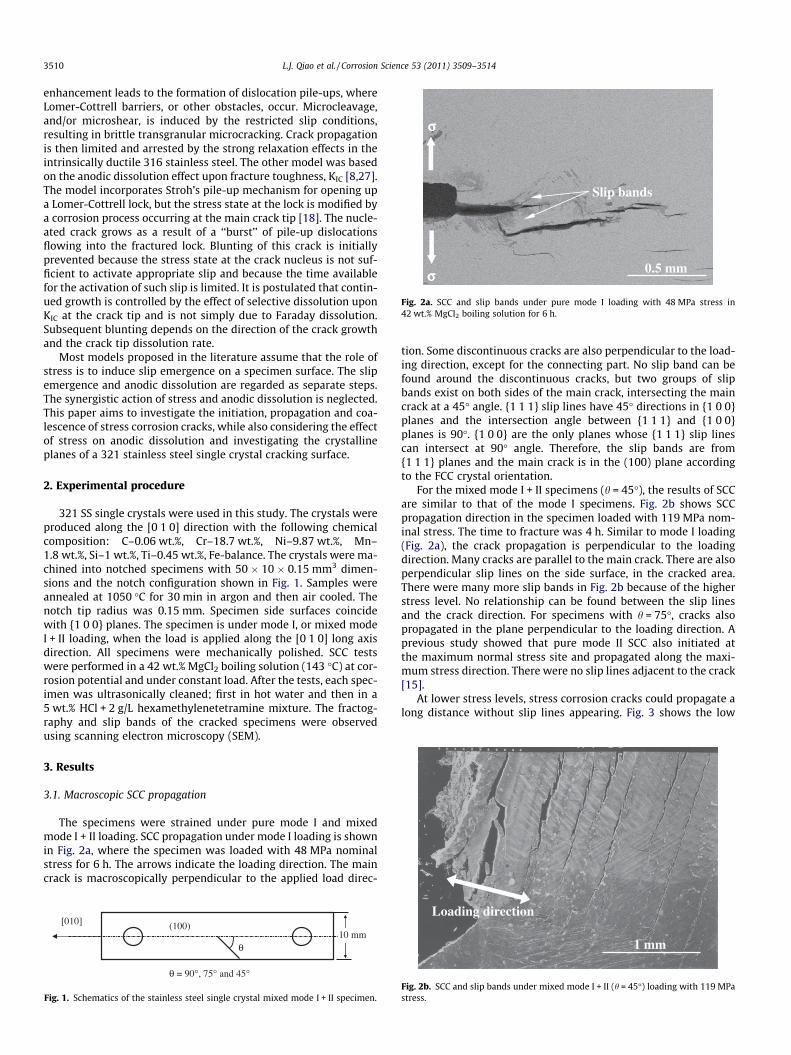
Fig. 2a. SCC and slip bands under pure mode I loading with 48 MPa stress in42 wt.% MgCl2 boiling solution for 6 h.
3510 L.J. Qiao et al. / Corrosion Science 53 (2011) 3509–3514
enhancement leads to the formation of dislocation pile-ups, whereLomer-Cottrell barriers, or other obstacles, occur. Microcleavage,and/or microshear, is induced by the restricted slip conditions,resulting in brittle transgranular microcracking. Crack propagationis then limited and arrested by the strong relaxation effects in theintrinsically ductile 316 stainless steel. The other model was basedon the anodic dissolution effect upon fracture toughness, KIC [8,27].The model incorporates Stroh’s pile-up mechanism for opening upa Lomer-Cottrell lock, but the stress state at the lock is modified bya corrosion process occurring at the main crack tip [18]. The nucle-ated crack grows as a result of a ‘‘burst’’ of pile-up dislocationsflowing into the fractured lock. Blunting of this crack is initiallyprevented because the stress state at the crack nucleus is not suf-ficient to activate appropriate slip and because the time availablefor the activation of such slip is limited. It is postulated that contin-ued growth is controlled by the effect of selective dissolution uponKIC at the crack tip and is not simply due to Faraday dissolution.Subsequent blunting depends on the direction of the crack growthand the crack tip dissolution rate.
Most models proposed in the literature assume that the role ofstress is to induce slip emergence on a specimen surface. The slipemergence and anodic dissolution are regarded as separate steps.The synergistic action of stress and anodic dissolution is neglected.This paper aims to investigate the initiation, propagation and coa-lescence of stress corrosion cracks, while also considering the effectof stress on anodic dissolution and investigating the crystallineplanes of a 321 stainless steel single crystal cracking surface.
2. Experimental procedure
321 SS single crystals were used in this study. The crystals wereproduced along the [0 1 0] direction with the following chemicalcomposition: C–0.06 wt.%, Cr–18.7 wt.%, Ni–9.87 wt.%, Mn–1.8 wt.%, Si–1 wt.%, Ti–0.45 wt.%, Fe-balance. The crystals were ma-chined into notched specimens with 50 � 10 � 0.15 mm3 dimen-sions and the notch configuration shown in Fig. 1. Samples wereannealed at 1050 �C for 30 min in argon and then air cooled. Thenotch tip radius was 0.15 mm. Specimen side surfaces coincidewith {1 0 0} planes. The specimen is under mode I, or mixed modeI + II loading, when the load is applied along the [0 1 0] long axisdirection. All specimens were mechanically polished. SCC testswere performed in a 42 wt.% MgCl2 boiling solution (143 �C) at cor-rosion potential and under constant load. After the tests, each spec-imen was ultrasonically cleaned; first in hot water and then in a5 wt.% HCl + 2 g/L hexamethylenetetramine mixture. The fractog-raphy and slip bands of the cracked specimens were observedusing scanning electron microscopy (SEM).
3. Results
3.1. Macroscopic SCC propagation
The specimens were strained under pure mode I and mixedmode I + II loading. SCC propagation under mode I loading is shownin Fig. 2a, where the specimen was loaded with 48 MPa nominalstress for 6 h. The arrows indicate the loading direction. The maincrack is macroscopically perpendicular to the applied load direc-
θ
θ = 90°, 75° and 45°
10 mm (100)[010]
Fig. 1. Schematics of the stainless steel single crystal mixed mode I + II specimen.
tion. Some discontinuous cracks are also perpendicular to the load-ing direction, except for the connecting part. No slip band can befound around the discontinuous cracks, but two groups of slipbands exist on both sides of the main crack, intersecting the maincrack at a 45� angle. {1 1 1} slip lines have 45� directions in {1 0 0}planes and the intersection angle between {1 1 1} and {1 0 0}planes is 90�. {1 0 0} are the only planes whose {1 1 1} slip linescan intersect at 90� angle. Therefore, the slip bands are from{1 1 1} planes and the main crack is in the (100) plane accordingto the FCC crystal orientation.
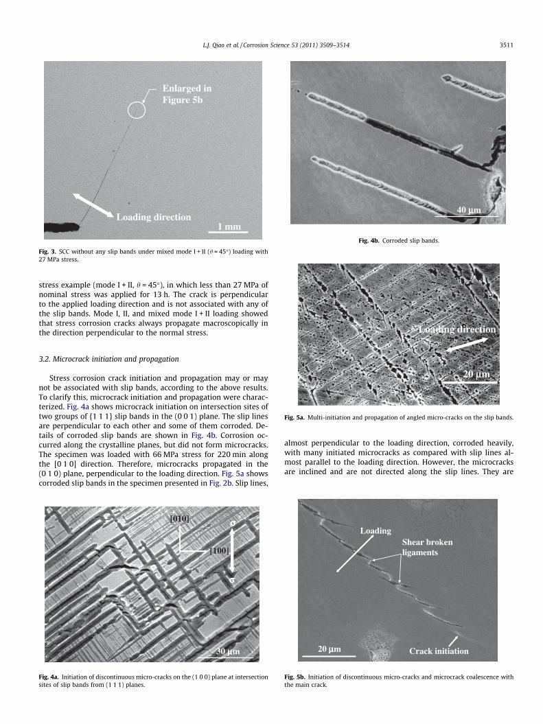
For the mixed mode I + II specimens (h = 45�), the results of SCCare similar to that of the mode I specimens. Fig. 2b shows SCCpropagation direction in the specimen loaded with 119 MPa nom-inal stress. The time to fracture was 4 h. Similar to mode I loading(Fig. 2a), the crack propagation is perpendicular to the loadingdirection. Many cracks are parallel to the main crack. There are alsoperpendicular slip lines on the side surface, in the cracked area.There were many more slip bands in Fig. 2b because of the higherstress level. No relationship can be found between the slip linesand the crack direction. For specimens with h = 75�, cracks alsopropagated in the plane perpendicular to the loading direction. Aprevious study showed that pure mode II SCC also initiated atthe maximum normal stress site and propagated along the maxi-mum stress direction. There were no slip lines adjacent to the crack[15].
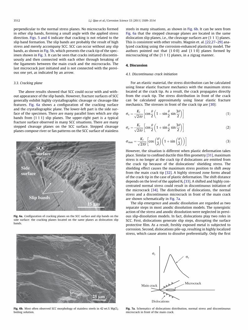
At lower stress levels, stress corrosion cracks could propagate along distance without slip lines appearing. Fig. 3 shows the low
Loading direction
1 mm
Fig. 2b. SCC and slip bands under mixed mode I + II (h = 45�) loading with 119 MPastress.
Loading direction
Enlarged in Figure 5b
1 mm
Fig. 3. SCC without any slip bands under mixed mode I + II (h = 45�) loading with27 MPa stress.
40 μμμμm
Fig. 4b. Corroded slip bands.
Loading direction
L.J. Qiao et al. / Corrosion Science 53 (2011) 3509–3514 3511
stress example (mode I + II, h = 45�), in which less than 27 MPa ofnominal stress was applied for 13 h. The crack is perpendicularto the applied loading direction and is not associated with any ofthe slip bands. Mode I, II, and mixed mode I + II loading showedthat stress corrosion cracks always propagate macroscopically inthe direction perpendicular to the normal stress.
20 μμm
Fig. 5a. Multi-initiation and propagation of angled micro-cracks on the slip bands.
3.2. Microcrack initiation and propagation
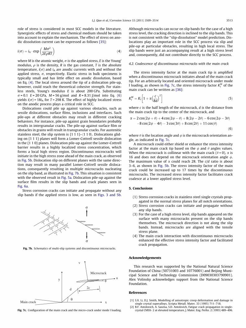
Stress corrosion crack initiation and propagation may or maynot be associated with slip bands, according to the above results.To clarify this, microcrack initiation and propagation were charac-terized. Fig. 4a shows microcrack initiation on intersection sites oftwo groups of {1 1 1} slip bands in the (0 0 1) plane. The slip linesare perpendicular to each other and some of them corroded. De-tails of corroded slip bands are shown in Fig. 4b. Corrosion oc-curred along the crystalline planes, but did not form microcracks.The specimen was loaded with 66 MPa stress for 220 min alongthe [0 1 0] direction. Therefore, microcracks propagated in the(0 1 0) plane, perpendicular to the loading direction. Fig. 5a showscorroded slip bands in the specimen presented in Fig. 2b. Slip lines,
30 μμμμm
σσσσ
σσσσ [[001100]]
[[110000]]
Fig. 4a. Initiation of discontinuous micro-cracks on the (1 0 0) plane at intersectionsites of slip bands from (1 1 1) planes.
almost perpendicular to the loading direction, corroded heavily,with many initiated microcracks as compared with slip lines al-most parallel to the loading direction. However, the microcracksare inclined and are not directed along the slip lines. They are
Shear broken ligaments
Crack initiation
Loading
20 μμμμm
Fig. 5b. Initiation of discontinuous micro-cracks and microcrack coalescence withthe main crack.
3512 L.J. Qiao et al. / Corrosion Science 53 (2011) 3509–3514
perpendicular to the normal stress planes. No microcracks formedin other slip bands, forming a small angle with the applied stressdirection. Figs. 5 and 6 indicate that cracking is not related to theslip band formation. The slip bands are probably the result of highstress and merely accompany SCC. SCC can occur without any slipbands, as shown in Fig. 5b, which presents the crack tip of the spec-imen shown in Fig. 3. It can be seen that cracks initiated discontin-uously and then connected with each other through breaking ofthe ligaments between the main crack and the microcracks. Thelast microcrack just initiated and is not connected with the previ-ous one yet, as indicated by an arrow.
3.3. Cracking plane
The above results showed that SCC could occur with and with-out appearance of the slip bands. However, fracture surfaces of SCCgenerally exhibit highly crystallographic cleavage or cleavage-likefeatures. Fig. 6a shows a configuration of the cracking surfaceand the crystallographic plane. The lower-left part is the side sur-face of the specimen. There are many parallel lines which are slipbands from {1 1 1} slip planes. The upper-right part is a typicalfracture surface observed in many SCC situations. There are manystepped cleavage planes on the SCC surface. Stepped cleavageplanes compose river or fan patterns on the SCC surface of stainless
Side surface
SCC surface
15 μμμμmSlip bands
Fig. 6a. Configuration of cracking planes on the SCC surface and slip bands on theside surface: the cracking planes located on the same planes as dislocation slipbands.
25 μμm
Fig. 6b. Most often observed SCC morphology of stainless steels in 42 wt.% MgCl2
boiling solution.
steels in many situations, as shown in Fig. 6b. It can be seen fromFig. 6a that the stepped cleavage planes are located in the samedislocation slip planes, i.e., the cleavage surfaces are {1 1 1} planes.This is consistent with other results. Magnin et. al. [22,27–29] ana-lyzed cracking using the corrosion-enhanced plasticity model. Theauthors pointed out that {1 0 0} and {1 1 0} planes formed bymicrocracking of the {1 1 1} planes, in a zigzag manner.
4. Discussion
4.1. Discontinuous crack initiation
For an elastic material, the stress distribution can be calculatedusing linear elastic fracture mechanics with the maximum stresslocated at the crack tip. As a result, the crack propagates directlyfrom the crack tip. The stress distribution in front of the crackcan be calculated approximately using linear elastic fracturemechanics. The stresses in front of the crack tip are [30]:
rx ¼KIffiffiffiffiffiffiffiffiffi2prp cos
h2
1� sinh2
sin3h2
� �� �ð1Þ
ry ¼KIffiffiffiffiffiffiffiffiffi2prp cos
h2
1þ sinh2
sin3h2
� �� �ð2Þ
rmax ¼KIffiffiffiffiffiffiffiffiffi2prp cos
h2
� �1þ sin
h2
� �� �� �ð3Þ
However, the situation is different when plastic deformation takesplace. Similar to confined ductile thin film geometry [31], maximumstress is no longer at the crack tip if dislocations are emitted fromthe crack tip because of the dislocations’ shielding stress. Theshielding effect causes the maximum stress position to shift awayfrom the main crack tip [32]. A highly stressed zone forms aheadof the crack tip in the case of plastic deformation. The shift distancedepends on the level of the applied KI [33]. A shifted and highly con-centrated normal stress could result in discontinuous initiation ofthe microcrack [34]. The distribution of dislocations, the normalstress and a discontinuous microcrack in front of the main crackare shown schematically in Fig. 7a.
The slip emergence and anodic dissolution are regarded as twoseparate steps in most anodic dissolution models. The synergisticaction of the stress and anodic dissolution were neglected in previ-ous slip-dissolution models. In fact, dislocations play two roles inSCC. First, dislocations generate slip steps, disrupting the surfaceprotective film. As a result, freshly exposed metal is subjected tocorrosion. Second, dislocations pile-up, resulting in highly localizedstress, which cause atoms to dissolve preferentially. Only the first
MicrocrackMain crack
σy
σy
Dislocations
ig. 7a. Schematics of dislocations distribution, normal stress and discontinuousicrocrack in front of the main crack.
Fm
L.J. Qiao et al. / Corrosion Science 53 (2011) 3509–3514 3513
role of stress is considered in most SCC models in the literature.Synergistic effects of stress and chemical medium should be takeninto account to explain the mechanism. The effect of stress on ano-dic dissolution current can be expressed as follows [35]:
iðrÞ ¼ iA � expMr2
2EqRT
� �ð4Þ
where M is the atomic weight, r is the applied stress, E is the Young’modulus, q is the density, R is the gas constant, T is the absolutetemperature, i(r) and iA are anodic currents with and without theapplied stress, r, respectively. Elastic stress in bulk specimens istypically small and has little effect on anodic dissolution, basedon Eq. (4). The local stress around the tip of a dislocation pile-up,however, could reach the theoretical cohesive strength. For stain-less steels, Young’s modulus E is about 200 GPa. Substitutingr = 0.1 E = 20 GPa, M = 56 g/mol and R = 8.31 J/mol into Eq. (6)yields i(r) = 18iA for T = 298 K. The effect of highly localized stresson the anodic process plays a critical role in SCC.
Dislocations could pile up against various obstacles, such assessile dislocations, surface films, inclusions and interfaces. Suchpile-ups at different obstacles may result in different crackingbehaviors. For instance, pile-up against grain boundaries probablyresults in intergranular cracks. The pile-up against surface film orobstacles in grains will result in transgranular cracks. For austeniticstainless steel, the slip system is {1 1 1}–h1 1 0i. Dislocations glid-ing on {1 1 1} planes will form a Lomer-Cottrell sessile dislocationin the {1 1 0} planes. Dislocation pile-up against the Lomer-Cottrellbarrier results in a highly localized stress concentration, whichforms a local high stress region. Discontinuous microcracks willinitiate in the high stress zone ahead of the main crack, as observedin Fig. 5b. Dislocation slip on different planes with the same direc-tion may result in many parallel Lomer-Cottrell sessile disloca-tions, consequently resulting in multiple microcracks nucleatingon the slip band, as illustrated in Fig. 7b. This situation is consistentwith the observed result in Fig. 5a. Dislocation pile-up against thesurface film results in the slip bands and crack planes seen inFig. 6a.
Stress corrosion cracks can initiate and propagate without anyslip bands if the applied stress is low, as seen in Figs. 3 and 5b.
σ
σ
Fig. 7b. Schematics of multi-slip systems and discontinuous microcracks.
θ
φ
x
y
d
u
v
2c
u
Main crack
Microcrack
Fig. 7c. Configuration of the main crack and the micro-crack under mode I loading.
Although microcracks can occur on slip bands for the case of a highstress level, the cracking direction is inclined to the slip bands. Thisis not consistent with the ‘‘slip-dissolution’’ model prediction. Dis-locations play an important role in the SCC process via slip andpile-up at particular obstacles, resulting in high local stress. Theslip bands were just an accompanying result at a high stress leveland, consequently, did not contribute directly to the SCC process.
4.2. Coalescence of discontinuous microcracks with the main crack
The stress intensity factor at the main crack tip is amplifiedwhen a discontinuous microcrack initiates ahead of the main cracktip. For an arbitrarily located and oriented microcrack under modeI loading, as shown in Fig. 7c, the stress intensity factor KM
I of themain crack can be written as [36]:
KMI ¼ KI 1þ a
c8d
� �2� �
ð5Þ
where c is the half length of the microcrack, d is the distance fromthe main crack tip to the center of the microcrack, and
a ¼ 2 cosð2/þ hÞ þ 4 cosð2/� hÞ þ 8ð2/� 2hÞ � 6 cosð2/� 3hÞ�8 cosð2/� 4hÞ � 3 cosð3hÞ þ 8 cosð2hÞ þ 11 cosðhÞ
ð6Þ
where h is the location angle and / is the microcrack orientation an-gle, as indicated in Fig. 7c.
A microcrack could either shield or enhance the stress intensityfactor at the main crack tip based on the / and h angles values.When the microcrack is collinear with the main crack (h = 0), a is16 and does not depend on the microcrack orientation angle /.The maximum value of a could reach 28. The c/d ratio is about3–6, as shown in Fig. 5b. The stress intensity factor of the maincrack could be increased up to 17 times by the discontinuousmicrocracks. The increased stress intensity factor facilitates crackcoalesce at a lower applied stress level.
5. Conclusions
(1) Stress corrosion cracks in stainless steel single crystals prop-agated in the normal stress planes for all notch orientations.
(2) Stress corrosion cracks can initiate and propagate withoutany slip bands.
(3) For the case of a high stress level, slip bands appeared on thesurface with many microcracks present on the slip bandsthemselves. The microcrack direction is not along the slipbands. Instead, microcracks are aligned with the tensilestress plane.
(4) The main crack interaction with discontinuous microcracksenhanced the effective stress intensity factor and facilitatedcrack propagation.
Acknowledgements
This research was supported by the National Natural ScienceFoundation of China (50731003 and 10776001) and Beijing Muni-cipal Science and Technology Commission (D09030303790901).Alex Volinsky acknowledges support from the National ScienceFoundation.
References
[1] S.X. Li, D.J. Smith, Modelling of anisotropic creep deformation and damage insingle crystal superalloys, Scripta Metall. Mater. 33 (1995) 711–718.
[2] B.F. Antolovich, A. Saxena, S.D. Antolovich, Fatigue crack propagation in single-crystal CMSX- 2 at elevated temperature, J. Mater. Eng. Perfor. 2 (1993) 489–496.
3514 L.J. Qiao et al. / Corrosion Science 53 (2011) 3509–3514
[3] H. Koizumi, S. Katakura, T. Suzuki, Crack propagation velocity in NaCl singlecrystals, Mater. Sci. Eng. A176 (1994) 417–420.
[4] H. Uchida, M. Yamashita, S. Inoue, K. Koterazawa, In-situ observations of cracknucleation and growth during stress corrosion by scanning vibrating electrodetechnique, Mater. Sci. Eng. A319–321 (2001) 496–500.
[5] D.E. Kramer, M.F. Savage, L.E. Levine, AFM observations of slip banddevelopment in Al single crystals, Acta Mater. 53 (2005) 4655–4664.
[6] K. Koterazawa, H. Uchida, T. Nonomura, Tensile orientation dependence ofhydrogen embrittlement in SUS304 stainless steel single crystals, J. Soc. Mater.Sci. 43 (1994) 867–873.
[7] K. Kitajima, Modelling of hydrogen-induced fracture in iron, Mater. Sci. Eng. A176 (1994) 249–253.
[8] B.D. Lichter, W.F. Flanagan, J.S. Kim, J.C. Elkenbracht, M. Van Hunen,Mechanistic studies of stress corrosion cracking: application of thecorrosion-assisted cleavage model to results using oriented single crystals,Corrosion 52 (1996) 453–464.
[9] M.G. Alvarez, S.A. Fernandez, J.R. Galvele, Stress corrosion cracking in singlecrystals of Ag–Au alloy, Corros. Sci. 42 (2000) 739–752.
[10] P. Arnoux, Atomistic simulations of stress corrosion cracking, Corros. Sci. 52(2010) 1247–1257.
[11] J.H. Driver, D. Jensen, N. Hansen, Large strain deformation structures inaluminium crystals with rolling texture orientations, Acta Metall. Mater. 42(1994) 3105–3114.
[12] A.V. Sameliuk, A.D. Vasilev, S.A. Firstov, Low temperature deformation andfracture behaviour of [1 0 0] and [1 1 0] chromium single crystals, Inter. J.Refract. Met. Hard Mater. 14 (1996) 249–255.
[13] A. Sato, K. Kon, S. Tsujikawa, Y. Hisamatsu, Effect of crystallographicorientation on dissolution behavior of stainless steels single crystal, Mater.Trans., JIM 37 (1996) 729–732.
[14] K. Kashiara, M. Tagami, F. Inoko, Deformed structure and crystal orientation atdeformation bands in h0 1 1i aluminum single crystals, Mater. Trans., JIM 37(1996) 564–571.
[15] L.J. Qiao, X. Mao, J.L. Luo, Micromechanics of stress corrosion cracking ofsingle-crystal austenitic type 321 stainless steel under mode II loading,Corrosion 52 (1996) 927–934.
[16] P.A.S. Reed, P.H. Tucker, M.R. Joyce, Effects of mixed mode loading on fatigueand creep–fatigue in SRR-99 single crystals, Mater. Sci. Eng. A 394 (2005) 256–265.
[17] A.L. Pilchak, A.H. Young, J.C. Williams, Stress corrosion cracking facetcrystallography of Ti–8Al–1Mo–1V, Corros. Sci. 52 (2010) 3287–3296.
[18] A.N. Stroh, The strength of Homer-Cottrell sessile dislocations, Phil. Mag. 1(1956) 489–502.
[19] T. Mimaki, Y. Nakazawa, S. Hashimoto, S. Miura, Stress corrosion cracking ofcopper bicrystals with h1 1 0i-Tilt R3, R9, and R11 coincident site latticeboundaries, Met. Trans. A 21A (1990) 2355–2361.
[20] E.I. Meletis, R.F. Hochman, The crystallography of stress corrosion cracking inface centered cubic single crystals, Corros. Sci. 24 (1984) 843–862.
[21] J.I. Dickson, S. Li, J.-P. Bailon and D. Tromans, The fractography of transgranularSCC in F.C.C. metals, in Parkins Symposium on Fundamental Aspects of StressCorrosion Cracking, in: S.M. Bruemmer, E.I. Meletis, R.H. Jones, W.W.Gerberich, F.P., Ford, and R.W. Staehle (Ed.), TMS, Warrendale, PA. (1992) 303
[22] T. Magnin, A. Chambreuil, B. Bayle, The corrosion-enhanced plasticity model forstress corrosion cracking in ductile fcc alloys, Acta Mater. 44 (1996) 1457–1470.
[23] J.P. Chateau, D. Delafosse, T. Magnin, Numerical simulations of hydrogen–dislocation interactions in fcc stainless steels.: part II: hydrogen effects oncrack tip plasticity at a stress corrosion crack, Acta Mater. 50 (2002) 1523–1538.
[24] K. Sieradzki, R.C. Newman, Brittle behavior of ductile metals during stress-corrosion cracking, Phil. Mag. A 51 (1985) 95–132.
[25] T. Magnin and J. Lepinoux, ‘‘Metallurgical aspects of the brittle SCC inaustenitic stainless steels’’, in Parkins Symposium on Fundamental Aspects ofStress Corrosion Cracking, edited by S.M. Bruemmer, E.I. Meletis, R.H. Jones,W.W. Gerberich, F.P. Ford, and R.W. Staehle, TMS, Warrendale, PA. (1992) 323.
[26] Y. Yao, L.J. Qiao, A.A. Volinsky, Hydrogen effects on stainless steel passive filmfracture studied by nanoindentation, Corros. Sci. 53 (2011) 2679–2683.
[27] W.F. Flanagan, P. Bastias, B.D. Lichter, A theory of transgranular stress-corrosion cracking, Acta Metall. Mater. 39 (1991) 695–705.
[28] T. Magnin, Environment sensitive fracture mechanisms, Solid StatePhenomena 35–36 (1994) 319–334.
[29] A. Chambreuil, J.P. Chateau, T. Magnin, Influence of the slip conditions on thestress corrosion cracking microprocesses in FCC materials, Scripta Mater. 37(1997) 1337–1343.
[30] J.F. Knott, Fundamentals of Fracture Mechanics, John Wiley & Sons Inc., NewYork 1973, p. 57.
[31] A.A. Volinsky, N.R. Moody, M.L. Kottke, W.W. Gerberich, Fiducial mark andnanocrack zone formation during thin film delamination, Phil. Mag. 82 (2002)3383–3391.
[32] M.J. Lii, X.F. Chen, Y. Katz, W.W. Gerberich, Dislocation modeling and acousticemission observation of alternating ductile/brittle events in Fe–3 wt%Sicrystals, Acta Metall. Mater. 38 (1990) 2435–2453.
[33] S.H. Chen, Y. Katz, W.W. Gerberich, Crack-tip strain fields and fracturemicroplasticity in hydrogen-induced cracking of Fe–3 wt% Si single crystals,Phl. Mag. A 63 (1991) 131–155.
[34] W.W. Gerberich, T.J. Foecke, Hydrogen effects on material behavior, in: R.Moody, A.W. Thompson (Eds.), NACE, Houston, 1989, p. 687.
[35] S.W. Dean, Stress Corrosion – New Approaches, ASTM, STP 610 (WestConshohochen, PA: ASTM, 1976), p. 308.
[36] S.X. Gong, H. Horii, General solution to the problem of microcracks near the tipof a main crack, J. Mech. Phys. Solids 37 (1989) 27–46.