Embed Size (px)
DESCRIPTION
Disruption Analysis of PP, VV, and Components. Opera 3D Model – Transient ELEKTRA Solver. Square shape plasma (same cross section area as circular shape). Fast mid-plane centered disruption 2 MA/ms Back ground field OH, TF and PF coils (#79). Eddy Current Centered Disruption – 60 Degree Model. - PowerPoint PPT Presentation
Citation preview
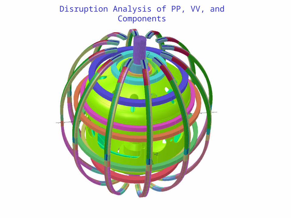
Disruption Analysis of PP, VV, and Components

Opera 3D Model – Transient ELEKTRA Solver
Fast mid-plane centered disruption 2 MA/msBack ground field OH, TF and PF coils (#79)
Square shape plasma (same cross section area as circular shape)

Passive Plate 5.97x10⁷ (Copper)
Gap between PP 1.35x10⁶ (SS)
VV 1.35x10⁶ (SS)
CS Casing 1.35x10⁶ (SS)
Electrical conductivity
Eddy Current Centered Disruption – 60 Degree Model
With gap between PPs – at end of disruption

1-2” air gap between plates
Eddy Current Centered Disruption – 60 Degree Model
Gap filled with weld between plates

Eddy current at end of disruption
Eddy Current Centered Disruption – 60 Degree Model

Disruption Analysis of PPs• 3D Opera model with square shape plasma (same J as circular shape)
• Background field from OH, TF, PF coils • Centered mid-plane disruption
– Fast disruption (2 MA/ms)– Eddy current in PPs, VV, CS-Casing
• Results
0
0.2
0.4
0.6
0.8
1
1.2
1.4
1.6
0 0.0005 0.001 0.0015 0.002 0.0025
Tota
l Tor
oida
l Cu
rren
t (M
A)
Time (s)
Eddy Current on VV and Casing
cs casing and vv
pp with gap
total (cs vv pp)
0
0.2
0.4
0.6
0.8
1
1.2
1.4
1.6
1.8
0 0.0005 0.001 0.0015 0.002 0.0025 0.003 0.0035
Tota
l Tor
oida
l Cu
rren
t (M
A)
Time (s)
Eddy Current on VV and Casing
cs casing and vv
pp with welding
Total (cs vv pp)
1-2” air gap between PPs Gap filled with SS (change loops in PPs)
Toroidal Current (%) Titus Zhai
VV+CS Casing 72% 75%
PPPs+SPPs 24% 25%
Comparison of total induced current (%)

Eddy Current Distribution on PP during Mid-Plane Disruption
Copper plates
Air gap

Eddy Current Distribution on PP during Mid-Plane Disruption
Copper plates
gap filled with SS

Disruption Analysis of PP, VV, and Components
• Discussion– Max background field– Vector potential from 2D continuous model (no gaps between PP)– Induced current from 2D model should in same direction?
• Recommendation– Design electrical conducting path to reduce eddy current gradient in PPs to
reduced eddies induced bending effect
Current Density (A/m2)
Titus Willard Zhai
VV (x107) 2.67~3.0 2.953 ~2.75
Comparison of peak current density

Disruption Analysis of PP, VV, and Components
• Opera Model – R. Hatcher – Max background field from PF and OH coils; no TF coils
– Mesh in radial direction to capture skin effect (skin depth?)
– Electrical conductivity• Passive plates • VV and CS casing – from measurement (SS?)
– Time varying vector potential solution (r*A? electrical scalar potential?)
• Opera Vector Potential input to 3D ANSYS model – P. Titus– ELEKTRA combination of total and reduced vector potentials
– Total vector potential
– Reduced vector potential
– Electrical scalar potential
01
RA
)(1
Vt
A
A
0)(
t
VA

Disruption Analysis of PP, VV, and Components
• Recommendation– Design electrical conducting path to reduce eddy current gradient in PPs
to reduced eddy induced bending effect?