Embed Size (px)
Citation preview
Distributed Mechanical Parameters of
Loudspeakers (Part 2: Diagnostics)
Parâmetros mecânicos distribuídos de alto falantes
(Parte 2: Diagnósticos)
Wolfgang Klippel1, Joachim Schlechter2
1University of Technology Dresden, Dresden, Germany, [email protected]
2KLIPPEL GmbH, Dresden, Germany, [email protected]
ABSTRACT
Distributed mechanical parameters describe the vibration and geometry of the sound radiating surface of
loudspeaker drive units. This data is the basis for predicting the sound pressure output and a decomposition of the
total vibration into modal and sound pressure related components. This analysis separates acoustical from
mechanical problems, shows the relationship to the geometry and material properties and gives indications for
practical improvement. A new kind of loudspeaker diagnostic becomes possible and a step by step methodology is
developed in this paper. Common problems are discussed in relation to design choices.
RESUMO
Os parâmetros mecânicos distribuídos descrevem a vibração e a geometria da superfície de radiação do som nos alto
falantes. Esta informação é a base para a previsão da saída da pressão sonora e para uma decomposição da vibração
total em componentes modais e de pressão sonora relacionada. Esta análise separa os problemas acústicos dos
Klippel et. al. Diagnostics on Cone Vibration and Sound Radiation
Page 2 of 32
mecânicos, mostra a relação entre a geometria e as propriedades do material e fornece indicações para melhorias
práticas. Um novo tipo de diagnóstico de alto falante torna-se possível e sua metodologia será desenvolvida passo a
passo neste trabalho. Problemas comuns são discutidos em relação às escolhas de projetos.
1. INTRODUCTION INTRODUÇÃO
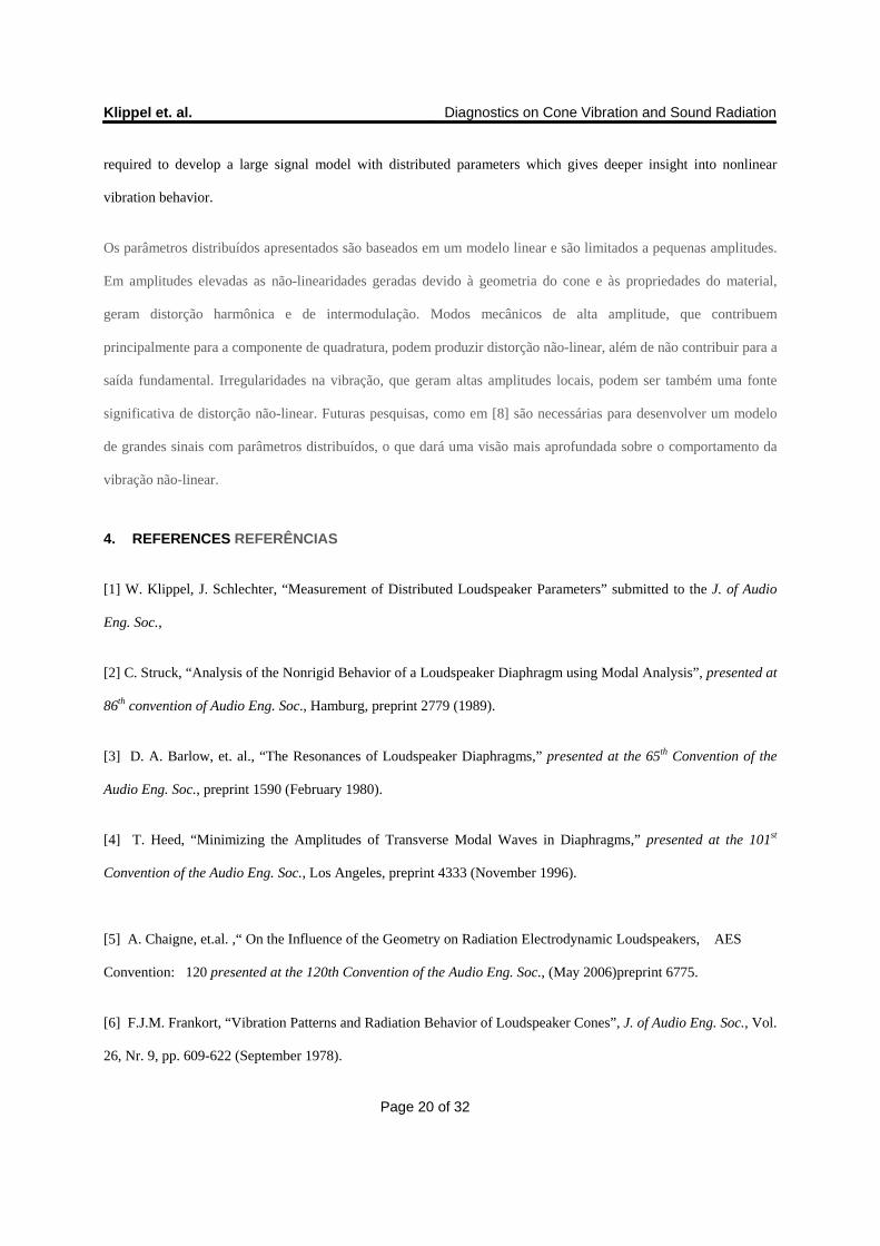
The mechanical vibration of a loudspeaker drive unit can be represented by distributed parameters which consist of a
set of linear transfer functions and the geometry of the radiator (cone, dome, diaphragm, piston, panel) as defined in
a previous paper [1]. The transfer functions ),( cx rjH between the input voltage )( jU and the displacement
),( crjX of the radiator’s surface can be measured by using a laser scanning technique or can be predicted by
using finite element analysis (FEA) and material properties (Young’s modulus E and loss factor as illustrated in
Fig. 1.
A vibração mecânica de um driver pode ser representada por parâmetros distribuídos, que consistem de um conjunto
de funções de transferência linear e da geometria do radiador (cone, membrana, diafragma, pistão, painel), tal como
definido em um artigo anterior [1]. As funções de transferência ),( cx rjH entre a tensão de entrada, )( jU , e o
deslocamento , ),( crjX , da superfície do radiador, podem ser medidas através da técnica de varredura à laser ou
previstas por meio da análise de elementos finitos (FEA) e pelas propriedades do material (Módulo de Young E e
fator de perda , como ilustrado na Fig. 1.
The sound pressure at any point in the sound field can be predicted by Boundary Element Analysis (BEA) using the
distributed parameters and the shape and properties of other acoustical elements (horn, enclosure, room, …) as input
information [2]-[5]. Thus distributed parameters supplement the lumped parameters considering the nonlinear and
thermal properties of the motor and suspension and provide for each drive unit a comprehensive set of data as input
for loudspeaker system design.
A pressão sonora em qualquer ponto do campo de som pode ser previsto pela Análise de Elemento de Contorno
(BEA), usando os parâmetros distribuídos e a forma e propriedades de outros elementos acústicos (corneta, gabinete,
sala,...) como informações de entrada [2] - [5]. Parâmetros assim distribuídos complementam os parâmetros
Klippel et. al. Diagnostics on Cone Vibration and Sound Radiation
Page 3 of 32
concentrados, considerando as propriedades não-lineares e térmicas do motor e da suspensão, e fornecendo, para
cada driver, um conjunto abrangente de dados como entrada para projeto de sistema de alto-falante.
This paper focuses on the practical interpretation of the distributed parameters and shows the diagnostic value for
identifying common problems related to the mechanical vibration and acoustical radiation. This kind of analysis is
based on secondary characteristics which are derived from the primary data in [1] and make the relationship between
geometry and material properties of the radiator and the sound pressure output more transparent.
Este artigo tem como objetivo a interpretação prática dos parâmetros distribuídos e mostrar o valor de diagnóstico
para a identificação de problemas comuns relacionados às vibrações mecânicas e radiação acústica. Este tipo de
análise é baseada em características secundárias que são derivadas de dados primários em [1] e relacionam a
geometria e as propriedades do material do radiador com a saída de pressão sonora de uma forma mais transparente.
The radiated sound pressure level (SPL) can be predicted with a simple monopole approximation in the Rayleigh Eq.
6 in [1]. An accumulated acceleration level (AAL) is defined in Eq. 8 in [1] to summarize the mechanical vibration to
a quantity which is comparable to the sound pressure output. The sound power is also an integrative measure which
summarizes the directional response pattern into a single-valued characteristic.
O nível de pressão sonora radiado (SPL) pode ser previsto com uma aproximação do monopólo simples na
Rayleigh, Eq.6 em [1]. Um nível de aceleração acumulada (AAL) é definido na Eq. 8 em [1] para resumir a vibração
mecânica para uma quantidade que seja compatível à saída de pressão sonora. A potência sonora também é uma
medida integrativa, a qual resume o padrão de resposta direcional em uma característica de valor único.
Modal analysis describes the total vibration by the linear superposition of a few numbers of independent modes.
Each mode can separately be investigated by considering shape of the vibration pattern, the natural frequency and
the modal loss factor.
A análise modal descreve a vibração total da superposição linear de um número menor de modos independentes.
Cada modo pode ser analisado separadamente, considerando a forma do padrão de vibração, a freqüência natural e o
fator de perda modal.
Klippel et. al. Diagnostics on Cone Vibration and Sound Radiation
Page 4 of 32
If the radiator has an axial-symmetrical shape the circumferential modes can be separated from the radial
component.
Se o radiador tiver uma forma axial simétrica, os modos circunferenciais podem ser separados da componente radial.
The new sound pressure related decomposition shows the contribution of each surface element to the total sound
pressure at a receiving point ra in the sound field. An in-phase vibration component which constructively
contributes to the sound pressure can be separated from an anti-phase vibration component which destructively
contributes to the sound pressure at the point ra. The remaining quadrature component gives valuable information
about vibration which is not contributing to the sound pressure at the point ra (e.g. acoustical cancellation of rocking
modes).
A decomposição relacionada à uma nova pressão sonora mostra a contribuição de cada elemento da superfície para a
pressão sonora total em um ponto de recebimento ra no campo de som. Uma componente de vibração em fase
construtiva contribui para a pressão sonora e pode ser separada de uma componente de vibração anti-fase destrutiva,
que contribui para a pressão sonora no ponto ra. A componente de quadratura restante dá informações importantes
sobre a vibração que não está contribuindo para a pressão sonora no ponto ra (por exemplo, o cancelamento acústico
de modos de balanço).
The diagnostic value of the distributed parameters shall be illustrated in this paper on following drive units:
Woofer A using a conventional 11 cm paper cone
Woofer B using a 11 cm magnesium cone
Woofer C using a 12 cm flat piston as radiator
Horn compression driver with a 6 cm aluminum dome.
O valor do diagnóstico dos parâmetros distribuídos são ilustrados neste artigo nas seguintes unidades de
acionamento:
Woofer A usando um cone de papel de 11 cm convencional
Woofer B usando um cone de magnésio de 11 cm
Woofer C usando um pistão flat de 12 cm como radiador
Klippel et. al. Diagnostics on Cone Vibration and Sound Radiation
Page 5 of 32
Driver corneta com um domo de alumínio de 6cm
2. DIAGNOSTICS OF VIBRATION AND RADIATION PROBLEMS DIAGNÓSTICO DE PROBLEMAS
DE VIBRAÇÃO E RADIAÇÃO
The drive units are operated virtually in an infinite baffle and the radiation into the half space is investigated. The
influence of the enclosure, horn and acoustical system which is finally coupled to the drive unit is neglected. For this
kind of diagnostics the sound radiation in the far field can be approximated with the Rayleigh equation (Eq. 6 in [1])
at minimal computational load.
As unidades de acionamento são operadas virtualmente em um baffle infinito e a radiação em meio espaço é
analisada. A influência do gabinete, da corneta e do sistema acústico, cujo os quais são por fim acoplados à unidade
de acionamento, é desprezada. Para este tipo de diagnóstico, a radiação do som no campo distante pode ser
aproximada com a equação de Rayleigh (Eq. 6 em [1]) para uma carga computacional mínima.
2.1. Smooth SPL Response Resposta SPL suave
Significant peaks and dips in the sound pressure response impair the sound quality and are perceived as coloration.
In the first step of the analysis the SPL response is calculated at a point on axis and a few degrees out of axis. Those
responses may represent the direct sound varying over the listening area. The flatness and smoothness of the
responses are investigated and the critical frequencies are determined.
Picos e quedas significativas na resposta de pressão sonora prejudicam a qualidade do som e são percebidos como
coloração. Na primeira etapa da análise da resposta SPL, estas respostas são calculadas em um ponto no eixo e
alguns graus fora do eixo e podem representar o som direto variando sobre a área audível. A planicidade e suavidade
das respostas são analisadas e as freqüências críticas são determinadas.
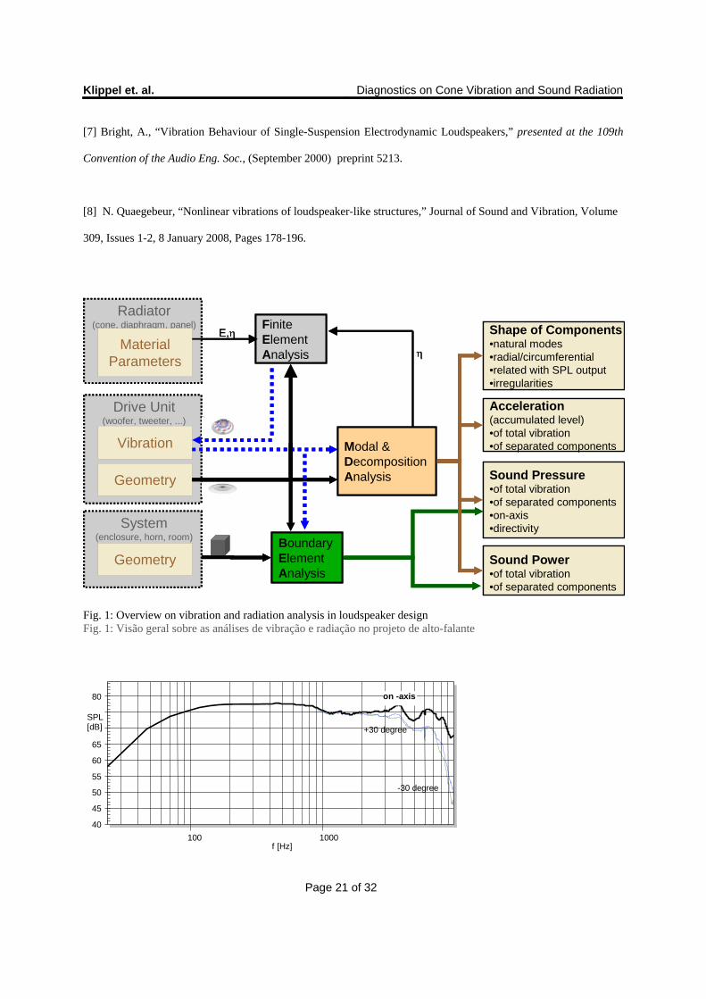
Fig. 2 shows a relatively flat and smooth SPL response of woofer A using a conventional paper cone. At 1 kHz the
SPL on-axis and +- 30 degree off-axis drops by 3 dB but then they stay constant up to 4 kHz. Fig. 3 shows the on-
axis SPL response as thick solid line of woofer B using a magnesium cone which is almost constant up to 6 kHz.
Only the SPL responses measured +/- 30 degree out of axis decrease above 2 kHz. The distinct peaks above 8 kHz
Klippel et. al. Diagnostics on Cone Vibration and Sound Radiation
Page 6 of 32
are not relevant for a woofer application. Fig. 4 shows the SPL responses of woofer C using a flat piston as radiator.
There is a 6dB peak at 800 Hz and a significant dip at 1.1kHz both in on-axis and off-axis responses which is not
acceptable for the particular application.
A Fig. 2 mostra uma resposta SPL relativamente plana e lisa do woofer A, usando um cone de papel convencional.
Em 1 kHz, o SPL no eixo e + - 30 graus fora do eixo, cai 3 dB, porém até 4 kHz permanece constante. A Fig. 3
mostra a resposta SPL do woofer B, usando um cone de magnésio, no eixo como linha sólida grossa, que é quase
constante até 6 kHz. Apenas as respostas SPL medidas a + / - 30 graus para fora do eixo obtiveram redução acima de
2 kHz. Os picos distintos acima de 8 kHz não são relevantes para uma aplicação no woofer. A Fig. 4 mostra as
respostas SPL do woofer C, usando um pistão flat como radiador. Há um pico de 6dB a 800 Hz e uma queda
significativa em 1.1kHz, tanto na resposta no eixo como fora do eixo, o que não é aceitável para a aplicação
particular.
2.2. Desired Directivity Diretividade desejada
For critical frequencies (where the peaks and dips occur) it is useful to investigate the variation of the SPL over a
larger number of the angles. This is important for the radiated sound power response which determines the diffuse
sound in enclosed spaces (rooms).
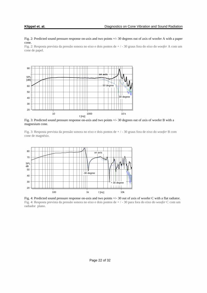
Fig. 5 shows for example the directivity of woofer C at the critical frequency 1.1 kHz which indicates that the dip is
limited to a certain angle and the sound power response is less affected than the on-axis response.
Para frequências críticas (onde ocorrem os picos e quedas), é importante analisar a variação do SPL em um maior
número de ângulos. Isso é importante para a resposta de potência sonora radiada, a qual determina o som difuso em
espaços fechados (salas).
A Fig. 5 mostra, por exemplo, a diretividade do woofer C na frequência crítica, 1.1 kHz, indicando que a queda é
limitada a um certo ângulo e a resposta de potência sonora é menos afetada do que a resposta no eixo.
Klippel et. al. Diagnostics on Cone Vibration and Sound Radiation
Page 7 of 32
2.3. Sufficient Mechanical Vibration Vibração mecânica suficiente
The analysis of the vibration should start with the calculation of the accumulated acceleration level (AAL). This level
shows the maximal possible SPL by summarizing the volume velocity of all points on the radiator’s surface while
neglecting phase differences.
A análise da vibração deve começar com o cálculo do nível de aceleração acumulada (AAL). Este nível mostra o
máximo SPL possível, resumindo a velocidade do volume de todos os pontos na superfície do radiador, quando
desprezadas as diferenças de fase.
The acceleration level is identical with the on-axis SPL response at lower frequencies where the radiating surface
vibrates as a rigid body and no acoustical cancellation occurs. At higher frequencies there are peaks in the
acceleration level which are placed at the natural frequencies of the mechanical modes.
O nível de aceleração é idêntico à resposta SPL no eixo em freqüências mais baixas, onde a superfície radiante vibra
como um corpo rígido e não ocorre nenhum cancelamento acústico. Em freqüências mais altas, há picos no nível de
aceleração, que são colocados nas freqüências naturais dos modos mecânicos.
The woofer A with the paper cone produces a peak in AAL at 1.1 kHz as shown in Fig. 6 which is not visible in the
SPL response. The dip in the SPL response at 5 kHz corresponds with a lack of accumulated acceleration.
O woofer A, com o cone de papel, produz um pico na AAL em 1,1 kHz, como mostrado na Fig. 6, que não é visível
na resposta SPL. A queda na resposta SPL em 5 kHz corresponde à falta de aceleração acumulada.
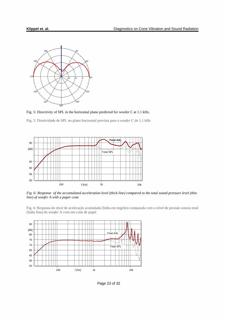
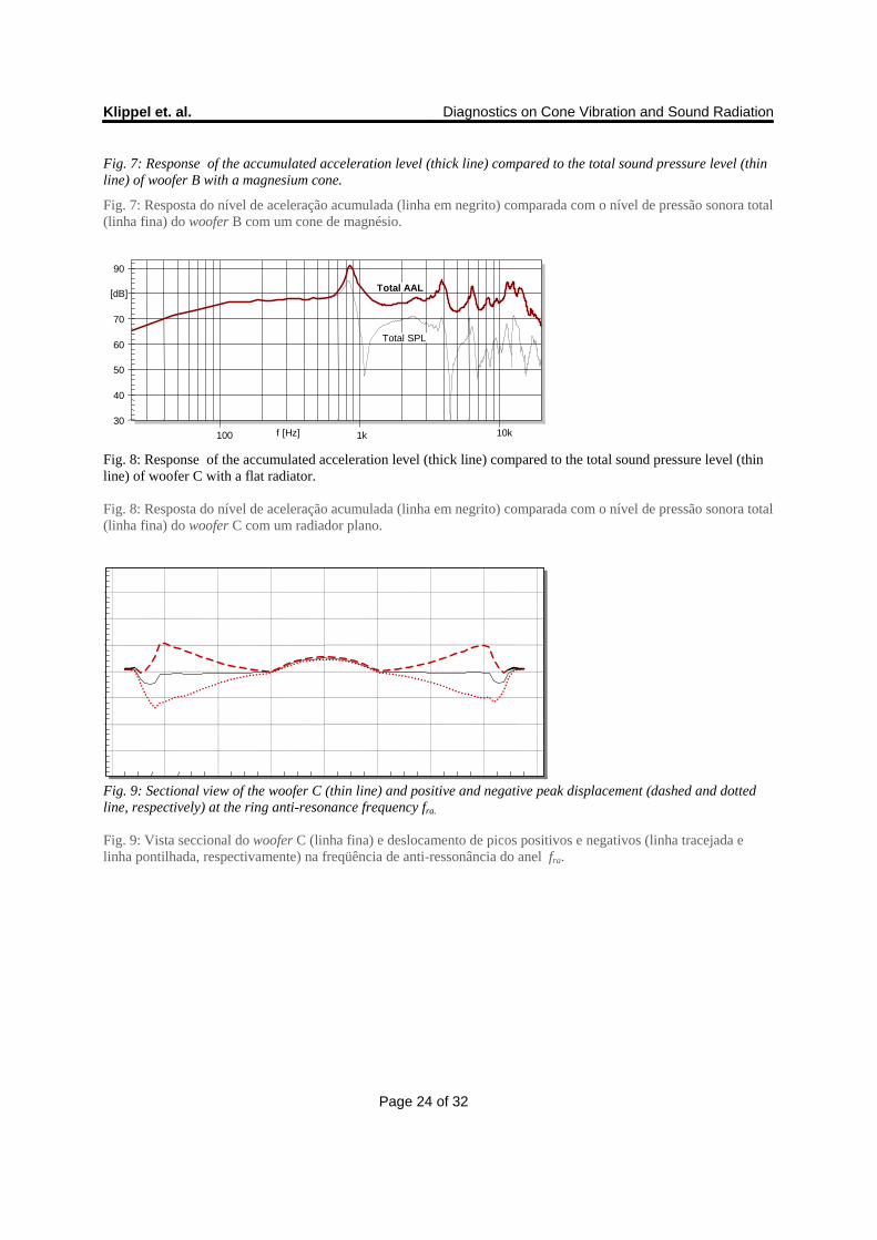
For woofer B with the magnesium cone both AAL and SPL responses are identical up to 2 kHz as shown in Fig. 7.
The acceleration stays also constant up to 4 kHz and shows significant peaks of 10 –15 dB at the natural frequencies.
Above 10 kHz, where the moving mass of the coil dominates the total mechanical impedance, the AAL decreases
dramatically.
Para o woofer B, com cone de magnésio, ambas respostas AAL e SPL são idênticas até 2 kHz, como mostrado na
Fig.7. A aceleração também permanece constante até 4 kHz e mostra picos significativos de 10-15dB nas
Klippel et. al. Diagnostics on Cone Vibration and Sound Radiation
Page 8 of 32
frequências naturais. Acima de 10 kHz, onde a massa em movimento da bobina domina a impedância mecânica
total, a AAL diminui drasticamente.
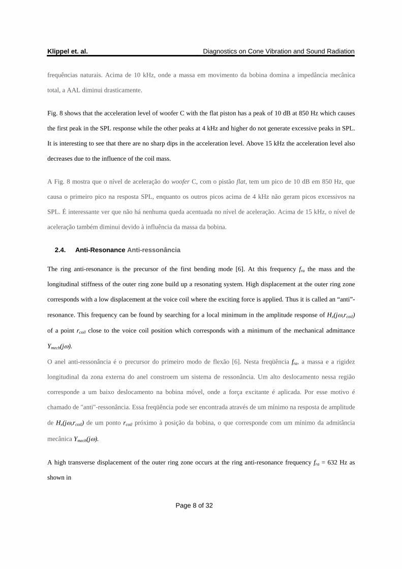
Fig. 8 shows that the acceleration level of woofer C with the flat piston has a peak of 10 dB at 850 Hz which causes
the first peak in the SPL response while the other peaks at 4 kHz and higher do not generate excessive peaks in SPL.
It is interesting to see that there are no sharp dips in the acceleration level. Above 15 kHz the acceleration level also
decreases due to the influence of the coil mass.
A Fig. 8 mostra que o nível de aceleração do woofer C, com o pistão flat, tem um pico de 10 dB em 850 Hz, que
causa o primeiro pico na resposta SPL, enquanto os outros picos acima de 4 kHz não geram picos excessivos na
SPL. É interessante ver que não há nenhuma queda acentuada no nível de aceleração. Acima de 15 kHz, o nível de
aceleração também diminui devido à influência da massa da bobina.
2.4. Anti-Resonance Anti-ressonância
The ring anti-resonance is the precursor of the first bending mode [6]. At this frequency fra the mass and the
longitudinal stiffness of the outer ring zone build up a resonating system. High displacement at the outer ring zone
corresponds with a low displacement at the voice coil where the exciting force is applied. Thus it is called an “anti”-
resonance. This frequency can be found by searching for a local minimum in the amplitude response of Hx(j,rcoil)
of a point rcoil close to the voice coil position which corresponds with a minimum of the mechanical admittance
Ymech(j).
O anel anti-ressonância é o precursor do primeiro modo de flexão [6]. Nesta freqüência fra, a massa e a rigidez
longitudinal da zona externa do anel constroem um sistema de ressonância. Um alto deslocamento nessa região
corresponde a um baixo deslocamento na bobina móvel, onde a força excitante é aplicada. Por esse motivo é
chamado de "anti"-ressonância. Essa freqüência pode ser encontrada através de um mínimo na resposta de amplitude
de Hx(j,rcoil) de um ponto rcoil próximo à posição da bobina, o que corresponde com um mínimo da admitância
mecânica Ymech(j).
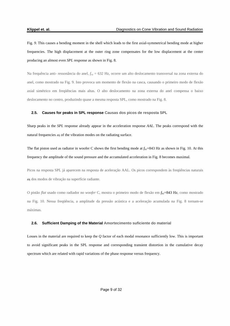
A high transverse displacement of the outer ring zone occurs at the ring anti-resonance frequency fra = 632 Hz as
shown in
Klippel et. al. Diagnostics on Cone Vibration and Sound Radiation
Page 9 of 32
Fig. 9. This causes a bending moment in the shell which leads to the first axial-symmetrical bending mode at higher
frequencies. The high displacement at the outer ring zone compensates for the low displacement at the center
producing an almost even SPL response as shown in Fig. 8.
Na frequência anti- ressonância do anel, fra = 632 Hz, ocorre um alto deslocamento transversal na zona externa do
anel, como mostrado na Fig. 9. Isto provoca um momento de flexão na casca, causando o primeiro modo de flexão
axial simétrico em freqüências mais altas. O alto deslocamento na zona externa do anel compensa o baixo
deslocamento no centro, produzindo quase a mesma resposta SPL, como mostrado na Fig. 8.
2.5. Causes for peaks in SPL response Causas dos picos de resposta SPL
Sharp peaks in the SPL response already appear in the acceleration response AAL. The peaks correspond with the
natural frequencies i of the vibration modes on the radiating surface.
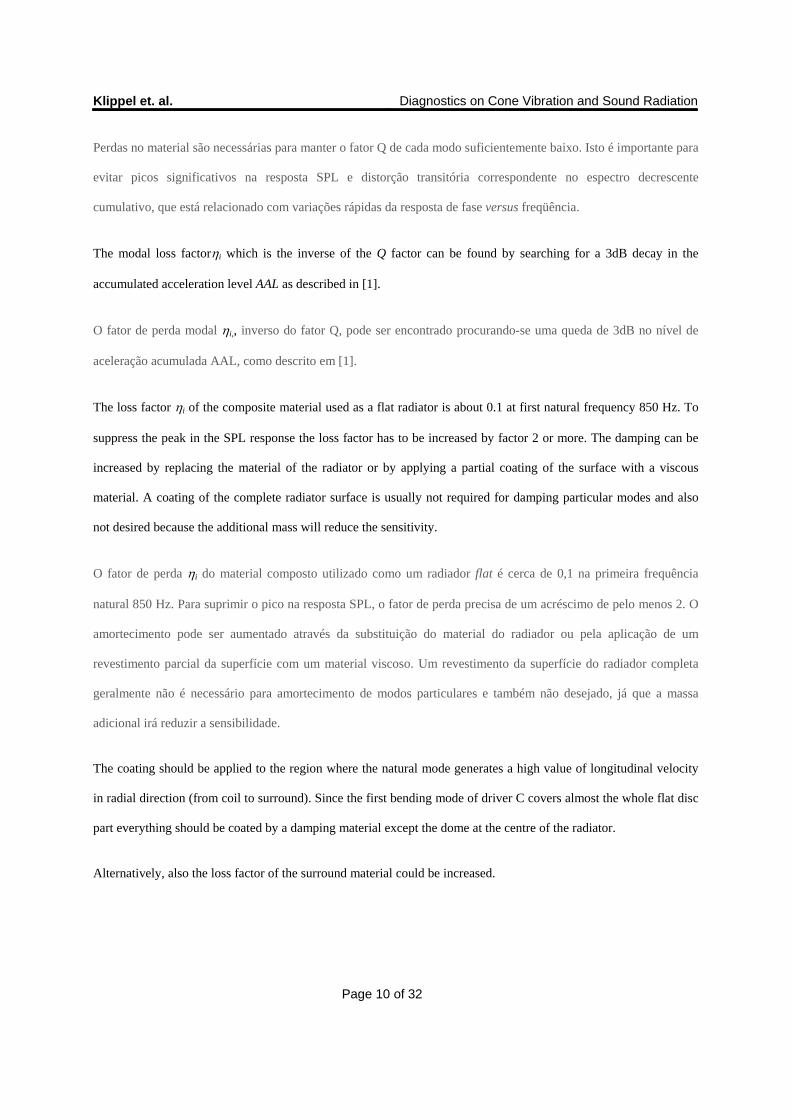
The flat piston used as radiator in woofer C shows the first bending mode at fb1=843 Hz as shown in Fig. 10. At this
frequency the amplitude of the sound pressure and the accumulated acceleration in Fig. 8 becomes maximal.
Picos na resposta SPL já aparecem na resposta de aceleração AAL. Os picos correspondem às freqüências naturais
i dos modos de vibração na superfície radiante.
O pistão flat usado como radiador no woofer C, mostra o primeiro modo de flexão em fb1=843 Hz, como mostrado
na Fig. 10. Nessa freqüência, a amplitude da pressão acústica e a aceleração acumulada na Fig. 8 tornam-se
máximas.
2.6. Sufficient Damping of the Material Amortecimento suficiente do material
Losses in the material are required to keep the Q factor of each modal resonance sufficiently low. This is important
to avoid significant peaks in the SPL response and corresponding transient distortion in the cumulative decay
spectrum which are related with rapid variations of the phase response versus frequency.
Klippel et. al. Diagnostics on Cone Vibration and Sound Radiation
Page 10 of 32
Perdas no material são necessárias para manter o fator Q de cada modo suficientemente baixo. Isto é importante para
evitar picos significativos na resposta SPL e distorção transitória correspondente no espectro decrescente
cumulativo, que está relacionado com variações rápidas da resposta de fase versus freqüência.
The modal loss factori which is the inverse of the Q factor can be found by searching for a 3dB decay in the
accumulated acceleration level AAL as described in [1].
O fator de perda modal i,, inverso do fator Q, pode ser encontrado procurando-se uma queda de 3dB no nível de
aceleração acumulada AAL, como descrito em [1].
The loss factor i of the composite material used as a flat radiator is about 0.1 at first natural frequency 850 Hz. To
suppress the peak in the SPL response the loss factor has to be increased by factor 2 or more. The damping can be
increased by replacing the material of the radiator or by applying a partial coating of the surface with a viscous
material. A coating of the complete radiator surface is usually not required for damping particular modes and also
not desired because the additional mass will reduce the sensitivity.
O fator de perda i do material composto utilizado como um radiador flat é cerca de 0,1 na primeira frequência
natural 850 Hz. Para suprimir o pico na resposta SPL, o fator de perda precisa de um acréscimo de pelo menos 2. O
amortecimento pode ser aumentado através da substituição do material do radiador ou pela aplicação de um
revestimento parcial da superfície com um material viscoso. Um revestimento da superfície do radiador completa
geralmente não é necessário para amortecimento de modos particulares e também não desejado, já que a massa
adicional irá reduzir a sensibilidade.
The coating should be applied to the region where the natural mode generates a high value of longitudinal velocity
in radial direction (from coil to surround). Since the first bending mode of driver C covers almost the whole flat disc
part everything should be coated by a damping material except the dome at the centre of the radiator.
Alternatively, also the loss factor of the surround material could be increased.
Klippel et. al. Diagnostics on Cone Vibration and Sound Radiation
Page 11 of 32
O revestimento deve ser aplicado na região onde o modo natural gera um elevado valor da velocidade longitudinal
na direção radial (da bobina para a borda). Quando o primeiro modo de flexão do driver C cobrir quase toda a parte
do disco flat, este deve ser revestido por um material de amortecimento, exceto o domo no centro do radiador.
Outra alternativa seria aumentar o fator de perda do material da borda.
2.7. Causes for dips in SPL response Causas das quedas na resposta SPL
The difference between the SPL response and AAL response is caused by a partial compensation of the volume
velocities generated by different parts on the radiators surface. The sound pressure related decomposition can help to
identify problems of acoustical cancellation. In that case the in-phase component and the anti-phase component have
the same acceleration level AAL which is identical with the SPL generated by each component. The summation of an
almost equal in-phase and anti-phase component results in a strong dip in the total SPL response.
A diferença entre a resposta SPL e a AAL é devido à uma compensação parcial da velocidade de volume gerada por
diferentes partes da superfície nos radiadores. A decomposição da pressão sonora relacionada pode ajudar a
identificar problemas de cancelamento acústico. Neste caso, a componente em fase e a componente anti-fase tem o
mesmo nível de aceleração AAL, que é idêntico ao SPL gerado por cada componente. A soma das componentes em
fase com componentes anti-fase quase iguais, resulta em uma queda brusca na resposta SPL total.
Fig. 11 shows the result of the sound pressure related decomposition for the 5 inch example drive unit. In the piston
mode the anti-phase component is almost negligible and would only produce 20 dB output if the other components
are not considered. Above the ring anti-resonance frequency fra=632 Hz the anti-phase component rises steadily and
becomes maximal at the first bending mode fb1=843 Hz. At this frequency the anti-phase component is almost 10dB
below the in-phase component. The acoustical cancellation occurs at 1.1kHz, 4.4kHz and 7kHz where the in-phase
and anti-phase components become identical.
A Fig. 11 mostra o resultado da decomposição da pressão sonora relacionada para a unidade de acionamento de 5”,
por exemplo. No modo pistão, a componente anti-fase é quase desprezível e só produzirá uma saída de 20 dB,
quando as outras componentes não forem consideradas. Acima da freqüência de anti-ressonância do anel fra=632 Hz,
a componente anti-fase aumenta de forma constante e torna-se máxima no primeiro modo de flexão fb1=843 Hz.
Klippel et. al. Diagnostics on Cone Vibration and Sound Radiation
Page 12 of 32
Nessa freqüência, a componente anti-fase está quase 10dB abaixo da componente em-fase. O cancelamento acústico
ocorre em 1.1kHz, 4.4kHz e 7kHz onde as componentes em fase e anti-fase são idênticas.
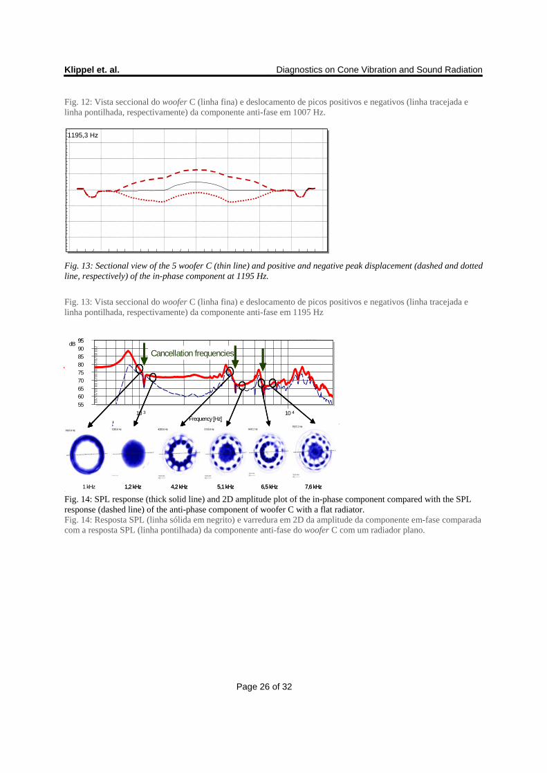
The location of the in-phase component gives a deeper understanding of the cancellation process at 1.1kHz. Passing
the cancellation frequency the in-phase component moves from the outside ring to the centre of the piston as shown
in Fig. 12 and Fig. 13.
A localização da componente em fase dá uma compreensão mais aprofundada do processo de cancelamento em
1.1kHz. Passando a frequência de cancelamento, a componente em fase movimenta-se do anel externo para o centro
do pistão, como mostrado na Fig. 12 e Fig. 13.
The in-phase component switches its position also at 4.4 kHz, 7 kHz, 8.5 kHz, 10 kHz and 15 kHz just at the
frequencies where the SPL (or AAL) of the in-phase component equals the anti-phase component.
A componente em fase alterna a sua posição também em 4,4 kHz, 7 kHz, 8,5 kHz, 10 kHz e 15 kHz, apenas nas
freqüências onde a SPL (ou AAL) da componente em-fase é igual a componente anti-fase.
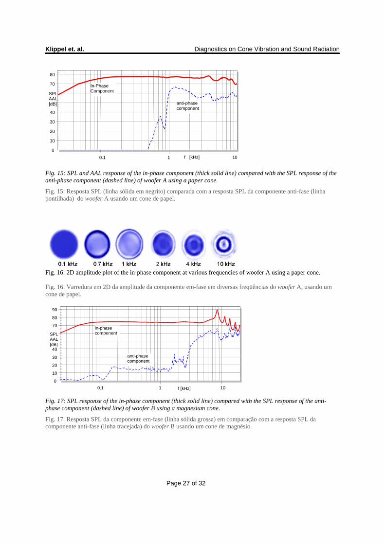
Woofer A and B using a conventional paper and magnesium cone, respectively, show a completely different
behavior. The SPL (AAL) of the anti-phase component in Fig. 15 and Fig. 17 is always more than 10 dB below the
in-phase component. Therefore, there are no acoustical cancellation effects causing dips in the SPL response. The
anti-phase components generated above the ring anti-resonance frequency fra spread with rising frequency from the
outside edge to the center and push the in-phase back to the inner region of the cone as shown in Fig. 16 and Fig. 18.
Like that both cones reduce their effective radiation area towards higher frequencies. This also reduces the effective
moving mass as seen by the driving force generated by the coil which increases the real part of the acoustical
radiation impedance and likewise the acoustical output power. Furthermore the radiation at higher frequencies
becomes less directive because of the shrinking size of the effective radiation area. Both effects make it possible to
build drive units which can be used over the full audio band.
Os woofers A e B, usando um cone de papel convencional e de magnésio, respectivamente, apresentam um
comportamento completamente diferente. O SPL (AAL) da componente anti-fase na Fig. 15 e Fig. 17 está sempre
mais do que 10 dB abaixo da componente em-fase, portanto, não há efeitos de cancelamento acústico causando
Klippel et. al. Diagnostics on Cone Vibration and Sound Radiation
Page 13 of 32
quedas na resposta SPL. As componentes anti-fase geradas acima da freqüência de anti-ressonância do anel fra ,
espalham-se com uma freqüência crescente a partir da borda externa até o centro do cone e empurram as
componentes em fase de volta à região interna do cone como se os dois cones reduzissem sua área de radiação
efetiva para freqüências mais altas, como mostrado na Fig. 16 e Fig. 18.. Isso também reduz a massa em movimento
efetiva, como pode-se observar através da força motriz gerada pela bobina, que aumenta a parte real da impedância
de radiação acústica e a potência de saída acústica. Além disso, a radiação em freqüências mais altas torna-se menos
diretiva por causa do tamanho reduzido da área de radiação efetiva. Ambos efeitos tornam possível a construção de
um driver, que pode ser utilizado em toda banda de áudio.
2.8. Avoid acoustical cancellations Evitando cancelamentos acústicos
The SPL or AAL of the in-phase component should be at least 6 dB higher than the SPL or AAL of the anti-phase
component to avoid acoustical cancellation and dips in the total SPL response. If the in-phase component is always
dominant it will be bounded to a fixed region on the radiator’s surface which shrinks in size at higher frequencies.
Conventional paper cones with an apex angle less than 70 degree break up gradually from outside. The first node
occurs close to the outer rim because the shell is there less curved than towards the center and the bending stiffness
is much lower.
Para evitar o cancelamento acústico e quedas na resposta SPL total, é necessário que o SPL, ou AAL, da
componente em-fase seja pelo menos 6 dB maior que o SPL, ou AAL, da componente anti-fase. Se a componente
em fase for sempre dominante, será limitada a uma região fixa na superfície do radiador, a qual reduz de tamanho
em freqüências mais altas. Cones de papel convencionais, com um ângulo de ápice menor que 70 graus quebram
gradualmente de fora para o centro. O primeiro nó ocorre perto da borda externa, pois a casca é menos curva do que
o centro e a rigidez à flexão é muito menor.
Piston drivers such as used in woofer C or shallow cones with a high apex angle (> 70 degree) generate a first node
which is located closer to the center leading to a strong anti-phase component. Using a material with a different
Young’s modulus E will usually not solve this problem because the cancellation point will only be shifted in
frequency but the mode shape and the position of the node will be similar. A variation of the loss factor will not
solve the cancellation problem either. The only solution is to change the shape of the mode by varying the
Klippel et. al. Diagnostics on Cone Vibration and Sound Radiation
Page 14 of 32
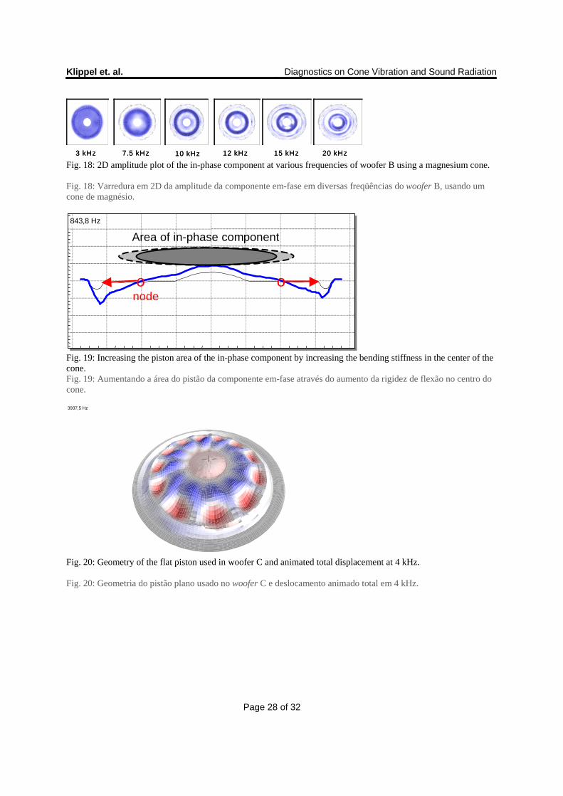
distributed mass or bending stiffness on the shell versus radius r. This can be accomplished by using a shell which
becomes thicker for lower radii or placing additional bracing below the piston in the inner region which increases
the bending stiffness there while keeping a low bending stiffness in the outside region. Thus, also a flat radiator will
have its first bending node closer to the outer rim and gets a dominant in-phase component in the center of the
radiator as illustrated in Fig. 19.
Drivers pistão, como os utilizados no woofer C ou cones rasos com um ângulo de ápice elevado (> 70 graus), geram
um primeiro nó localizado mais perto do centro, orientando-se para uma forte componente anti-fase. Usando um
material com um módulo de Young E diferente geralmente não resolve este problema, pois o ponto de cancelamento
desloca-se apenas em freqüência, porém a forma do modo e a posição do nó permanecem similares. A variação do
fator de perda também não resolve o problema de cancelamento, a única solução é mudar a forma do modo através
da variação da massa distribuída ou da rigidez à flexão na casca versus o raio r. Isso pode ser feito usando uma
casca, que torna-se mais grossa com raios menores ou colocando um suporte adicional abaixo do pistão, na região
interna, o que aumenta a rigidez à flexão, mantendo uma baixa rigidez à flexão na região externa. Assim, um
radiador flat também terá seu primeiro nó de flexão mais perto da borda externa e receberá uma componente em fase
dominante no centro do radiador, como ilustrado na Fig. 19.
2.9. Dominant circumferential modes Modos circuferenciais dominantes
Loudspeaker drive units with a round shape do not only show modes in radial direction but also in circular direction.
Circular modes may become more dominant in case there are any irregularities at the circumference such as wires or
e.g. additional 12 bracings below the piston in woofer C as shown in Fig. 20.
Unidades de acionamento de alto-falante com um formato redondo, não mostram apenas os modos na direção radial,
mas também na direção circular. Modos circulares podem tornar-se mais dominantes caso haja qualquer
irregularidade na borda, como por exemplo, fios ou 12 suportes adicionais abaixo do pistão no woofer C, de acordo
com a Fig.20.
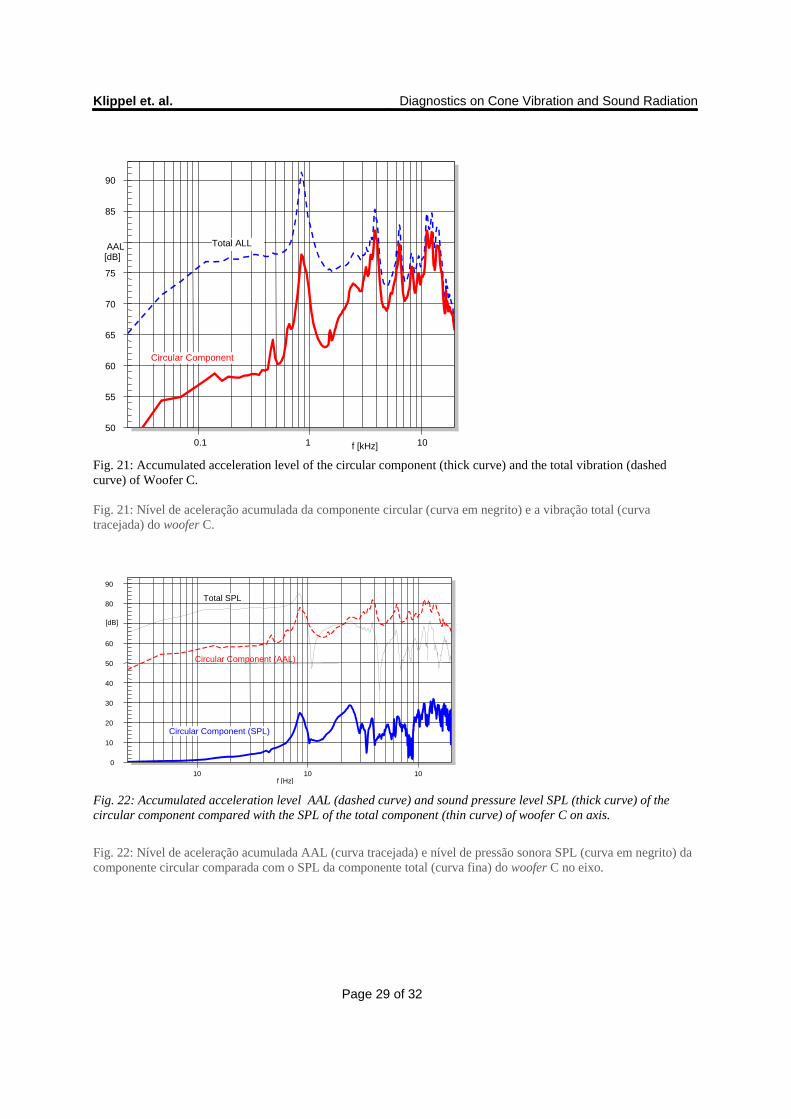
Since woofer C has an axial-symmetrical shape a decomposition into a radial and a circumferential vibration
component can be applied, as presented in [1]. The acceleration level of the circular component shown as thick solid
line in Fig. 21 is at higher natural frequencies only 3 dB below the total acceleration level shown as dashed line.
Klippel et. al. Diagnostics on Cone Vibration and Sound Radiation
Page 15 of 32
Uma vez que o woofer C tem uma forma axial simétrica, uma decomposição em uma radial e uma componente de
vibração circunferencial pode ser aplicada, conforme apresentado em [1]. O nível de aceleração da componente
circular mostrado como linha sólida espessa na Fig. 21 está, em freqüências naturais maiores, apenas 3 dB abaixo do
nível de aceleração total mostrado como linha tracejada.
Although the circular component has high mechanical energy it generates 50 dB less SPL on axis normal to the
radiator’s plane as shown as thick solid curve in Fig. 22. The radial component generates the dominant contribution
to the on-axis SPL (thin curve) which is 40 dB higher than the SPL output of the circular mode.
Embora a componente circular possua energia mecânica elevada, ela gera 50 dB menos SPL no eixo normal da
superfície do radiador, conforme mostrado como curva sólida e espessa na Fig. 22. A componente radial gera a
contribuição dominante para o eixo SPL (curva fina), que é 40 dB mais alto do que a saída SPL do modo circular.
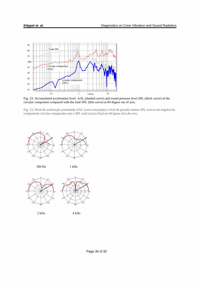
For a measurement point which is 60 degree out of axis the SPL of the circular component shown in Fig. 23 as thick
solid curve is 30 dB higher and contributes to the total SPL output significantly.
Para um ponto de medição 60 graus fora do eixo, o SPL da componente circular, mostrado na Fig. 23 como curva
sólida e espessa, é 30 dB mais alto e contribui significativamente para a saída SPL total.
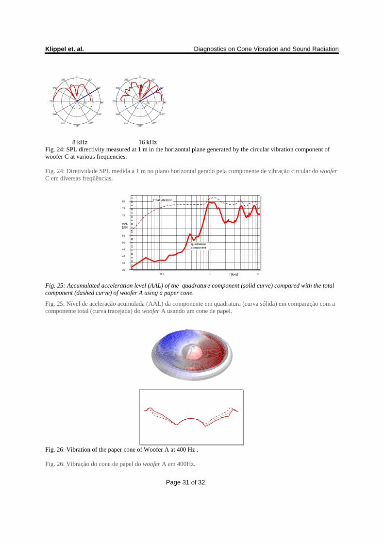
The directivity plots of the circular component in Fig. 24 reveal a high SPL output for high angles off-axis at all
frequencies. Thus circular components which do not have much impact on the on-axis response may be important
for reducing the directivity of a speaker producing a dispersive sound.
Os plots de diretividade da componente circular na Fig. 24 revelam uma alta saída SPL em todas as freqüências para
ângulos maiores fora do eixo. Assim, as componentes circulares que não tem muito impacto na resposta no eixo,
podem ser importantes na redução da diretividade de um falante produzindo um som disperso.
2.10. Rocking modes Modos de balanço
The first circumferential mode on the surround causes a rocking movement of the cone and the voice coil former.
This may cause a rubbing of the voice coil in the gap which could produce audible distortion and could even lead to
a permanent damage of the speaker. Rocking modes do not contribute significantly to the total sound pressure
Klippel et. al. Diagnostics on Cone Vibration and Sound Radiation
Page 16 of 32
output. The best indicator for rocking modes and any other circumferential modes is the accumulated acceleration
level (AAL) of the quadrature component.
O primeiro modo circunferencial na borda causa um movimento de balanço do cone e da bobina móvel. Isso pode
causar um atrito da bobina móvel no gap, podendo produzir uma distorção audível ou até mesmo causar um dano
permanente do falante. Os modos de balanço não contribuem significativamente na produção global de pressão
sonora, o melhor indicador para os modos de balanço e quaisquer outros modos circunferenciais é o nível de
aceleração acumulada (AAL) da componente de quadratura.
Below cone break-up where the acceleration level of the quadrature component is much smaller than the total
component there is a distinct peak at 380 Hz in Fig. 25. This is caused by a rocking mode of woofer A as shown in
Fig. 26.
Abaixo do cone break-up, onde o nível de aceleração da componente de quadratura é muito menor do que a
componente total, há um pico distinto em 380 Hz na Fig. 25. Isto é causado por um modo de balanço do woofer A,
como mostrado na Fig. 26.
Clearly the paper cone itself behaves like a rigid shell but the rocking mode causes significant deformation of the
surround. Flat loudspeakers using a low cone height and headphones and micro-speakers dispensing with a spider
are prone to rocking modes
Claramente, o cone de papel em si comporta-se como uma casca rígida, porém o modo de balanço provoca uma
deformação significativa da borda. Alto-falantes planos, usando um cone baixo, fones de ouvido e micro-falantes,
dispensando uma aranha, são propensos a modos de balanço
[7]. Any angular variation of the stiffness of the surround and the additional inertia of the wires initialize and
support rocking modes. Rocking modes may have significant amplitude in the acceleration level but can hardly be
detected in the radiated sound pressure output.
[7]. Qualquer variação angular da rigidez da borda e da inércia adicional dos fios inicializam e favorecem os modos
de balanço, que podem ter uma amplitude significativa no nível de aceleração, mas dificilmente podem ser
detectados na saída de pressão sonora radiada.
Klippel et. al. Diagnostics on Cone Vibration and Sound Radiation
Page 17 of 32
2.11. Irregular Vibrations Vibrações irregulares
Besides axial-symmetrical and circumferential there are other irregular vibrations on the shell which can usually not
be predicted by finite element analyses.
Além das vibrações axial simétrica e circunferencial, existem outras vibrações irregulares na casca, que
normalmente não podem ser previstas por meio de análises de elementos finitos.
Such irregularities may be caused by unbalanced mass distributions, non-uniform density or thickness of the shell
caused by intended bracing and unintended folds generated during shape forming of the radiator.
Estas irregularidades podem ser causadas por distribuições em massa desequilibradas, densidade não uniforme ou
espessura da casca causada pelo suporte e pelas dobras não intencionais geradas durante a formação do radiador.
The contribution of most irregularities to the total SPL and total AAL is relatively small but the irregular vibration
may cause excessive nonlinear distortion because the displacement may be much higher at particular points.
Irregular vibrations cause peaks in the AAL response of the quadrature component and in circular component. Those
characteristics are useful indicators for detecting irregularities.
A contribuição da maioria das irregularidades para o SPL e AAL total é relativamente pequena, porém a vibração
irregular pode causar uma distorção não-linear excessiva, pois o deslocamento pode ser muito maior em
determinados pontos. Vibrações irregulares causam picos na resposta AAL da componente de quadratura e circular.
Essas características são indicadoras úteis para a detecção de irregularidades.
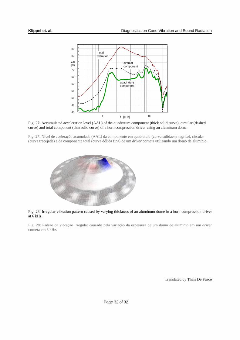
The scanning data of a horn compression driver reveals a small peak at 6kHz in the AAL response of both circular
and quadrature components in Fig. 27 which is not visible in the total AAL and SPL response. Fig. 28 shows that a
small region close to the center of the dome vibrates at much higher displacement than the remaining dome area.
Os dados de varredura de um driver corneta revelam um pequeno pico em 6 kHz na resposta AAL, tanto na
componente circular quanto na componente de quadratura, na Fig. 27, que não é visível na resposta total de AAL e
SPL. A Fig. 28 mostra que uma pequena região perto do centro da membrana vibra com um deslocamento muito
maior do que a área restante
Klippel et. al. Diagnostics on Cone Vibration and Sound Radiation
Page 18 of 32
3. CONCLUSION CONCLUSÃO
The distributed parameters reveal the mechanical properties of loudspeaker drive and the impact on the radiated
sound pressure output.
Os parâmetros distribuídos revelam as propriedades mecânicas do alto-falante e o impacto sobre a saída de pressão
sonora radiada.
Assessing the mechanical vibration on the radiator’s surface makes it possible to separate mechanical problems from
acoustical problems. Diagnostics on the radiator’s behavior should start with an analysis of the mechanical modes.
Derived characterististics like the accumulated acceleration level (AAL) and novel decomposition techniques
simplify the interpretation of the vibration pattern. The number of modes, the position of the natural frequencies and
the modal loss factor determine the smoothness of the AAL response which causes the peaks in SPL curve.
Distributed parameters measured by laser scanning reveals circumferential modes, rocking modes and other
irregular vibrations which are usually difficult to predict by finite element analysis (FEA).
Avaliando-se as vibrações mecânicas na superfície do radiador é possível separar os problemas mecânicos dos
problemas acústicos. Os diagnósticos do comportamento do radiador devem começar com uma análise dos modos
mecânicos. Características derivadas, como o nível de aceleração acumulada (AAL) e novas técnicas de
decomposição, simplificam a interpretação do padrão de vibração. O número de modos, a posição das freqüências
naturais e o fator de perda modal determinam a suavidade da resposta AAL, causando suaves picos na curva SPL.
Parâmetros distribuídos medidos por varredura à laser revelam modos circunferenciais, modos de balanço e outras
vibrações irregulares que normalmente são difíceis de serem previstas através da análise de elementos finitos (FEA).
The dominant problems in acoustical radiation can be found by calculating the in-phase and anti-phase component
which contribute in an constructive and destructive way, respectively, to the sound pressure output. Acoustical
cancellation and sharp dips in the SPL response can be avoided by generating a dominant in-phase component
having an AAL which is at least 6 dB higher than the contribution from the anti-phase component.
Os problemas dominantes na radiação acústica podem ser encontrados através do cálculo das componentes em-fase
e anti-fase, que contribuem de uma forma construtiva e destrutiva, respectivamente, para a saída da pressão sonora.
Klippel et. al. Diagnostics on Cone Vibration and Sound Radiation
Page 19 of 32
Cancelamento acústico e quedas bruscas na resposta SPL podem ser evitados através da geração de uma
componente em fase dominante, com um AAL no mínimo 6 dB maior do que a contribuição da componente anti-
fase.
Traditional paper cones with a small apex angle do not suffer from cancellation problems because there is a
dominant in-phase component in the center of the cone. The curvature of those cones causes a low bending stiffness
in the outer zone and the nodal lines of the first bending modes occur close to the outer rim generating only a small
anti-phase component.
Cones de papel tradicionais com um pequeno ângulo de ápice não sofrem de problemas de cancelamento porque não
possuem uma componente em fase dominante no centro do cone. A curvatura dos cones causa uma baixa rigidez de
flexão na zona externa e as linhas nodais dos modos de primeira dobra ocorrem perto da borda externa, gerando
apenas uma pequena componente anti-fase.
Shallow cones, panels or piston-like radiators like woofer C in this paper are prone to acoustical cancellation
problems because the first nodes divide the radiating area in competing parts producing a similar volume velocity.
Cones rasos, painéis ou pistão como radiadores, como no woofer C neste artigo, estão propensos a problemas de
cancelamento acústico, pois os primeiros nós dividem a área de radiação em partes concorrentes, produzindo uma
velocidade de volume similar.
A deeper understanding of the mechanical vibration and acoustical radiation is the basis for new ideas and design
choices which can be evaluated in greater detail by finite element analysis.
Uma compreensão mais aprofundada das vibrações mecânicas e da radiação acústica é a base para novas idéias e
projetos que podem ser avaliados com mais detalhes por análise de elementos finitos.
The distributed parameters presented here are based on a linear model and are limited to small amplitudes. At high
amplitudes the nonlinearities due to cone geometry and material properties generate harmonic and intermodulation
distortion. Mechanical modes of high amplitude which mainly contribute to the quadrature component can produce
nonlinear distortion while not contributing to the fundamental output. Irregularities in the vibration which generate
high local amplitudes may be also a significant source of nonlinear distortion. Further research such as in [8] is
Klippel et. al. Diagnostics on Cone Vibration and Sound Radiation
Page 20 of 32
required to develop a large signal model with distributed parameters which gives deeper insight into nonlinear
vibration behavior.
Os parâmetros distribuídos apresentados são baseados em um modelo linear e são limitados a pequenas amplitudes.
Em amplitudes elevadas as não-linearidades geradas devido à geometria do cone e às propriedades do material,
geram distorção harmônica e de intermodulação. Modos mecânicos de alta amplitude, que contribuem
principalmente para a componente de quadratura, podem produzir distorção não-linear, além de não contribuir para a
saída fundamental. Irregularidades na vibração, que geram altas amplitudes locais, podem ser também uma fonte
significativa de distorção não-linear. Futuras pesquisas, como em [8] são necessárias para desenvolver um modelo
de grandes sinais com parâmetros distribuídos, o que dará uma visão mais aprofundada sobre o comportamento da
vibração não-linear.
4. REFERENCES REFERÊNCIAS
[1] W. Klippel, J. Schlechter, “Measurement of Distributed Loudspeaker Parameters” submitted to the J. of Audio
Eng. Soc.,
[2] C. Struck, “Analysis of the Nonrigid Behavior of a Loudspeaker Diaphragm using Modal Analysis”, presented at
86th convention of Audio Eng. Soc., Hamburg, preprint 2779 (1989).
[3] D. A. Barlow, et. al., “The Resonances of Loudspeaker Diaphragms,” presented at the 65th Convention of the
Audio Eng. Soc., preprint 1590 (February 1980).
[4] T. Heed, “Minimizing the Amplitudes of Transverse Modal Waves in Diaphragms,” presented at the 101st
Convention of the Audio Eng. Soc., Los Angeles, preprint 4333 (November 1996).
[5] A. Chaigne, et.al. ,“ On the Influence of the Geometry on Radiation Electrodynamic Loudspeakers, AES
Convention: 120 presented at the 120th Convention of the Audio Eng. Soc., (May 2006)preprint 6775.
[6] F.J.M. Frankort, “Vibration Patterns and Radiation Behavior of Loudspeaker Cones”, J. of Audio Eng. Soc., Vol.
26, Nr. 9, pp. 609-622 (September 1978).
Klippel et. al. Diagnostics on Cone Vibration and Sound Radiation
Page 21 of 32
[7] Bright, A., “Vibration Behaviour of Single-Suspension Electrodynamic Loudspeakers,” presented at the 109th
Convention of the Audio Eng. Soc., (September 2000) preprint 5213.
[8] N. Quaegebeur, “Nonlinear vibrations of loudspeaker-like structures,” Journal of Sound and Vibration, Volume
309, Issues 1-2, 8 January 2008, Pages 178-196.
Radiator(cone, diaphragm, panel)
Drive Unit(woofer, tweeter, ...)
Geometry
BoundaryElementAnalysis
FiniteElementAnalysis
Sound Pressure•of total vibration •of separated components•on-axis•directivity
Vibration
MaterialParameters
E,
Acceleration(accumulated level)•of total vibration•of separated components
enclosure,horn, room
Modal & DecompositionAnalysis
System(enclosure, horn, room)
Geometry
Shape of Components•natural modes•radial/circumferential•related with SPL output•irregularities
Sound Power•of total vibration•of separated components
3937,5 Hz
Radiator(cone, diaphragm, panel)
Radiator(cone, diaphragm, panel)
Drive Unit(woofer, tweeter, ...)
Drive Unit(woofer, tweeter, ...)
Geometry
BoundaryElementAnalysis
FiniteElementAnalysis
Sound Pressure•of total vibration •of separated components•on-axis•directivity
Vibration
MaterialParameters
E,
Acceleration(accumulated level)•of total vibration•of separated components
enclosure,horn, room
Modal & DecompositionAnalysis
System(enclosure, horn, room)
System(enclosure, horn, room)
Geometry
Shape of Components•natural modes•radial/circumferential•related with SPL output•irregularities
Sound Power•of total vibration•of separated components
3937,5 Hz
Fig. 1: Overview on vibration and radiation analysis in loudspeaker design Fig. 1: Visão geral sobre as análises de vibração e radiação no projeto de alto-falante
40 45 50 55 60 65
80
100 1000
SPL [dB]
f [Hz]
+30 degree
-30 degree
on -axis
Klippel et. al. Diagnostics on Cone Vibration and Sound Radiation
Page 22 of 32
Fig. 2: Predicted sound pressure response on-axis and two points +/- 30 degrees out of axis of woofer A with a paper cone. Fig. 2: Resposta prevista da pressão sonora no eixo e dois pontos de + / - 30 graus fora do eixo do woofer A com um cone de papel.
20 30 40 50 60
90
10 1000 10 k
SPL [dB]
f [Hz]
30 degree
-30 degree
on axis
Fig. 3: Predicted sound pressure response on-axis and two points +/- 30 degrees out of axis of woofer B with a magnesium cone. Fig. 3: Resposta prevista da pressão sonora no eixo e dois pontos de + / - 30 graus fora de eixo do woofer B com cone de magnésio.
20 30 40 50
SPL dB
70 80
100 1k 10k
-30 degree
+ 30 degree
on axis
f [Hz]
Fig. 4: Predicted sound pressure response on-axis and two points +/- 30 out of axis of woofer C with a flat radiator. Fig. 4: Resposta prevista da pressão sonora no eixo e dois pontos de + / - 30 para fora do eixo do woofer C com um radiador plano.
Klippel et. al. Diagnostics on Cone Vibration and Sound Radiation
Page 23 of 32
0°
330
300
270
240
210
180°
150°
120°
90°
60°
30°
-15 -10 -5
Fig. 5: Directivity of SPL in the horizontal plane predicted for woofer C at 1.1 kHz. Fig. 5: Diretividade de SPL no plano horizontal prevista para o woofer C de 1,1 kHz
50 55 60 65
80
100 1k
[dB]
f [Hz]
Total SPL
Total AAL
10k
Fig. 6: Response of the accumulated acceleration level (thick line) compared to the total sound pressure level (thin line) of woofer A with a paper cone
Fig. 6: Resposta do nível de aceleração acumulada (linha em negrito) comparada com o nível de pressão sonora total (linha fina) do woofer A com um cone de papel
50 55 60 65 70 75 80
90
100 1k 10k
[dB]
f [Hz]
Total SPL
Total AAL
Klippel et. al. Diagnostics on Cone Vibration and Sound Radiation
Page 24 of 32
Fig. 7: Response of the accumulated acceleration level (thick line) compared to the total sound pressure level (thin line) of woofer B with a magnesium cone.
Fig. 7: Resposta do nível de aceleração acumulada (linha em negrito) comparada com o nível de pressão sonora total (linha fina) do woofer B com um cone de magnésio.
30 40 50 60 70
90
100 1k 10k
[dB]
f [Hz]
Total SPL
Total AAL
Fig. 8: Response of the accumulated acceleration level (thick line) compared to the total sound pressure level (thin line) of woofer C with a flat radiator. Fig. 8: Resposta do nível de aceleração acumulada (linha em negrito) comparada com o nível de pressão sonora total (linha fina) do woofer C com um radiador plano.
Fig. 9: Sectional view of the woofer C (thin line) and positive and negative peak displacement (dashed and dotted line, respectively) at the ring anti-resonance frequency fra.
Fig. 9: Vista seccional do woofer C (linha fina) e deslocamento de picos positivos e negativos (linha tracejada e linha pontilhada, respectivamente) na freqüência de anti-ressonância do anel fra.

Klippel et. al. Diagnostics on Cone Vibration and Sound Radiation
Page 25 of 32
843,8 Hz
Fig. 10: Sectional view of woofer C (thin line) and positive and negative peak displacement (dashed and dotted line, respectively) at the first bending resonance frequency fb1. Fig. 10: Vista seccional do woofer C (linha fina) e deslocamento de picos positivos e negativos (linha tracejada e linha pontilhada, respectivamente) na freqüência de ressonância da primeira dobra fb1.
0
10
20
30
40
70
80
90
0.10
1 10
SPL AAL [dB]
f [kHz]
in-phase component
anti-phase component
Fig. 11: AAL and SPL Response of the in-phase component and anti-phase component of woofer C with flat radiator. Fig. 11: Respostas AAL e SPL das componentes em-fase e anti-fase do woofer C com radiador plano.
1007,8 Hz
Fig. 12: Sectional view of woofer C with (thin line) and positive and negative peak displacement (dashed and dotted line, respectively) of the in-phase component at 1007 Hz.
Klippel et. al. Diagnostics on Cone Vibration and Sound Radiation
Page 26 of 32
Fig. 12: Vista seccional do woofer C (linha fina) e deslocamento de picos positivos e negativos (linha tracejada e linha pontilhada, respectivamente) da componente anti-fase em 1007 Hz.
1195,3 Hz
Fig. 13: Sectional view of the 5 woofer C (thin line) and positive and negative peak displacement (dashed and dotted line, respectively) of the in-phase component at 1195 Hz.
Fig. 13: Vista seccional do woofer C (linha fina) e deslocamento de picos positivos e negativos (linha tracejada e linha pontilhada, respectivamente) da componente anti-fase em 1195 Hz
KLIPPEL
55 60 65 70 75 80 85 90 95
10 3 10 4
dB - [V] (rms)
Frequency [Hz]
Cancellation frequencies
4,2 kHz 5,1 kHz 7,6 kHz6,5 kHz
Cancellation frequencies
55 60 65 70 75 80 85 90 95
10 3 10 4
dB
Frequency [Hz]
Cancellation frequenciesCancellation frequencies
1 kHz 1,2 kHz 4,2 kHz 5,1 kHz 7,6 kHz6,5 kHz1 kHz 1,2 kHz Fig. 14: SPL response (thick solid line) and 2D amplitude plot of the in-phase component compared with the SPL response (dashed line) of the anti-phase component of woofer C with a flat radiator. Fig. 14: Resposta SPL (linha sólida em negrito) e varredura em 2D da amplitude da componente em-fase comparada com a resposta SPL (linha pontilhada) da componente anti-fase do woofer C com um radiador plano.
Klippel et. al. Diagnostics on Cone Vibration and Sound Radiation
Page 27 of 32
0
10
20
30
40
70
80
0.1 1
SPL AAL [dB]
f [kHz]
In-Phase Component
anti-phase component
10
Fig. 15: SPL and AAL response of the in-phase component (thick solid line) compared with the SPL response of the anti-phase component (dashed line) of woofer A using a paper cone.
Fig. 15: Resposta SPL (linha sólida em negrito) comparada com a resposta SPL da componente anti-fase (linha pontilhada) do woofer A usando um cone de papel.
2 Fig. 16: 2D amplitude plot of the in-phase component at various frequencies of woofer A using a paper cone. Fig. 16: Varredura em 2D da amplitude da componente em-fase em diversas freqüências do woofer A, usando um cone de papel.
0
10
20
30
40
70
80
90
0.1 1 10
SPL AAL [dB]
f [kHz]
in-phase component
anti-phase component
Fig. 17: SPL response of the in-phase component (thick solid line) compared with the SPL response of the anti-phase component (dashed line) of woofer B using a magnesium cone.
Fig. 17: Resposta SPL da componente em-fase (linha sólida grossa) em comparação com a resposta SPL da componente anti-fase (linha tracejada) do woofer B usando um cone de magnésio.
Klippel et. al. Diagnostics on Cone Vibration and Sound Radiation
Page 28 of 32
20 kHz10 kHz 12 kHz 15 kHz7.5 kHz3 kHz 20 kHz10 kHz 12 kHz 15 kHz7.5 kHz3 kHz Fig. 18: 2D amplitude plot of the in-phase component at various frequencies of woofer B using a magnesium cone. Fig. 18: Varredura em 2D da amplitude da componente em-fase em diversas freqüências do woofer B, usando um cone de magnésio.
843,8 Hz
o o
Area of in-phase component
node
Fig. 19: Increasing the piston area of the in-phase component by increasing the bending stiffness in the center of the cone. Fig. 19: Aumentando a área do pistão da componente em-fase através do aumento da rigidez de flexão no centro do cone.
3937,5 Hz
Fig. 20: Geometry of the flat piston used in woofer C and animated total displacement at 4 kHz. Fig. 20: Geometria do pistão plano usado no woofer C e deslocamento animado total em 4 kHz.
Klippel et. al. Diagnostics on Cone Vibration and Sound Radiation
Page 29 of 32
50
55
60
65
70
75
85
90
0.1 1 10
AAL [dB]
f [kHz]
Total ALL
Circular Component
Fig. 21: Accumulated acceleration level of the circular component (thick curve) and the total vibration (dashed curve) of Woofer C. Fig. 21: Nível de aceleração acumulada da componente circular (curva em negrito) e a vibração total (curva tracejada) do woofer C.
0 10 20 30 40 50 60
80 90
10 10 10
[dB]
f [Hz]
Total SPL
Circular Component (SPL)
Circular Component (AAL)
Fig. 22: Accumulated acceleration level AAL (dashed curve) and sound pressure level SPL (thick curve) of the circular component compared with the SPL of the total component (thin curve) of woofer C on axis.
Fig. 22: Nível de aceleração acumulada AAL (curva tracejada) e nível de pressão sonora SPL (curva em negrito) da componente circular comparada com o SPL da componente total (curva fina) do woofer C no eixo.
Klippel et. al. Diagnostics on Cone Vibration and Sound Radiation
Page 30 of 32
10
20
30
40
50
70
80
90
0.1 1 10
[dB]
f [kHz]
Total SPL
circular component (SPL)
Circular component (AAL)
Fig. 23: Accumulated acceleration level AAL (dashed curve) and sound pressure level SPL (thick curve) of the circular component compared with the total SPL (thin curve) at 60 degree out of axis. Fig. 23: Nível de aceleração acumulada AAL (curva tracejada) e nível de pressão sonora SPL (curva em negrito) da componente circular comparada com o SPL total (curva fina) em 60 graus fora do eixo.
0°330
300
270
240
210180°
150°
120°
90°
60°
30°
-20 -10
0°330
300
270
240
210180°
150°
120°
90°
60°
30°
-10
500 Hz 1 kHz
0°330
300
270
240
210180°
150°
120°
90°
60°
30°
-10
0°330
300
270
240
210180°
150°
120°
90°
60°
30°
-30 -20 -10
2 kHz 4 kHz
Klippel et. al. Diagnostics on Cone Vibration and Sound Radiation
Page 31 of 32
0°330
300
270
240
210180°
150°
120°
90°
60°
30°
-20 -10
0°330
300
270
240
210180°
150°
120°
90°
60°
30°
-20 -10
8 kHz 16 kHz Fig. 24: SPL directivity measured at 1 m in the horizontal plane generated by the circular vibration component of woofer C at various frequencies. Fig. 24: Diretividade SPL medida a 1 m no plano horizontal gerado pela componente de vibração circular do woofer C em diversas freqüências.
30 35 40 45 50 55
70 75 80
0.1 1
AAL [dB]
f [kHz]
Total vibration
quadrature component
10
Fig. 25: Accumulated acceleration level (AAL) of the quadrature component (solid curve) compared with the total component (dashed curve) of woofer A using a paper cone.
Fig. 25: Nível de aceleração acumulada (AAL) da componente em quadratura (curva sólida) em comparação com a componente total (curva tracejada) do woofer A usando um cone de papel.
Fig. 26: Vibration of the paper cone of Woofer A at 400 Hz . Fig. 26: Vibração do cone de papel do woofer A em 400Hz.
Klippel et. al. Diagnostics on Cone Vibration and Sound Radiation
Page 32 of 32
40
45
50
55
60
65
70
80
85
1 10
AAL [dB]
f [kHz]
Total vibration
quadrature component
circular component
Fig. 27: Accumulated acceleration level (AAL) of the quadrature component (thick solid curve), circular (dashed curve) and total component (thin solid curve) of a horn compression driver using an aluminum dome. Fig. 27: Nível de aceleração acumulada (AAL) da componente em quadratura (curva sólidaem negrito), circular (curva tracejada) e da componente total (curva dólida fina) de um driver corneta utilizando um domo de alumínio.
Fig. 28: Irregular vibration pattern caused by varying thickness of an aluminum dome in a horn compression driver at 6 kHz. Fig. 28: Padrão de vibração irregular causado pela variação da espessura de um domo de alumínio em um driver corneta em 6 kHz.
Translated by Thais De Fusco