Embed Size (px)
Citation preview

Printed in Israel, September 1999
Owner’s Manual
68P02949C65-A
© Motorola Communications Israel Ltd., 1999A subsidiary of Motorola Inc.All rights reserved.
Land Mobile Products Sector
Land Mobile Products Sector
16 Kremenetski Street, Tel Aviv 67899
DIU3000
Digital Interface Unit
COMPUTER SOFTWARE COPYRIGHTS
The Motorola products described in this instruction manual may include copyrighted Motorola computer programs stored in semiconductor memories orother media. Laws in the United States and other countries preserve for Motorola certain exclusive rights for copyrighted computer programs, includingthe exclusive right to copy or reproduce in any form the copyrighted computer program. Accordingly, any copyrighted Motorola computer programs con-tained In the Motorola products described in this instruction manual may not be copied or reproduced in any manner without the express written permis-sion of Motorola. Furthermore, the purchase of Motorola products shall not be deemed to grant either directly or by implication, estoppel. or otherwise.any license under the copyrights, patents or patent applications of Motorola, except for the normal non-exclusive, royalty tree license to use that arisesby operation of law in the sale of a product.
EPS – 34440- B
This warranty applies within the fifty (50) United States, the District of Columbia and Canada.
LIMITED WARRANTY
MOTOROLA COMMUNICATION PRODUCTS
If the affected product is being purchased pursuant to a written Communications System Agreement signed by Motorola, the warranty contained in thatwritten agreement will apply. Otherwise, the following warranty applies.
I. WHAT THIS WARRANTY COVERS AND FOR HOW LONG:
Motorola Inc. or, if applicable, Motorola Canada Limited ("Motorola") warrants the Motorola manufactured radio communications product, includingoriginal equipment crystal devices and channel elements ("Product"), against material defects in material and workmanship under normal use andservice for a period of One (1) Year from the date of shipment.
Motorola, at its option, will at no charge either repair the Product (with new or reconditioned parts), replace it with the same or equivalent Product(using new or reconditioned Product), or refund the purchase price of the Product during the warranty period provided purchaser notifies Motorolaaccording to the terms of this warranty. Repaired or replaced Product is warranted for the balance of the original applicable warranty period. Allreplaced parts of the Product shall become the property of Motorola.
This express limited warranty is extended by Motorola to the original end user purchaser purchasing the Product for purposes of leasing or for com-mercial, industrial, or governmental use only, and is not assignable or transferable to any other party. This is the complete warranty for the Productmanufactured by Motorola. Motorola assumes no obligations or liability for additions or modifications to this warranty unless made in writing andsigned by an officer of Motorola. Unless made in a separate written agreement between Motorola and the original end user purchaser, Motorola doesnot warrant the installation, maintenance or service of the Product.
Motorola cannot be responsible in any way for any ancillary equipment not furnished by Motorola which is attached to or used in connection with theProduct, or for operation of the Product with any ancillary equipment, and all such equipment is expressly excluded from this warranty. Because eachsystem which may use the Product is unique, Motorola disclaims liability for range, coverage, or operation of the system as a whole under this war-ranty.
II. GENERAL PROVISIONS:
This warranty sets forth the full extent of Motorola’s responsibilities regarding the Product. Repair, replacement or refund of the purchase price, atMotorola’s option, is the exclusive remedy. THIS WARRANTY IS GIVEN IN LIEU OF ALL OTHER EXPRESS WARRANTIES. MOTOROLA DIS-CLAIMS ALL OTHER WARRANTIES OR CONDITIONS, EXPRESS OR IMPLIED, INCLUDING THE IMPLIED WARRANTIES OR CONDITIONS OFMERCHANTABILITY AND FITNESS FOR A PARTICULAR PURPOSE. IN NO EVENT SHALL MOTOROLA BE LIABLE FOR DAMAGES INEXCESS OF THE PURCHASE PRICE OF THE PRODUCT, FOR ANY LOSS OF USE, LOSS OF TIME, INCONVENIENCE, COMMERCIAL LOSS,LOST PROFITS OR SAVINGS OR OTHER INCIDENTAL, SPECIAL, INDIRECT OR CONSEQUENTIAL DAMAGES ARISING OUT OF THE USEOR INABILITY TO USE SUCH PRODUCT, TO THE FULL EXTENT SUCH MAY BE DISCLAIMED BY LAW.
III. HOW TO GET WARRANTY SERVICE:
Purchaser must notify Motorola’s representative or call Motorola’s Customer Response Center at 1-800-247-2346 within the applicable warrantyperiod for information regarding warranty service.
IV. WHAT THIS WARRANTY DOES NOT COVER:
A) Defects or damage resulting from use of the Product in other than its normal and customary manner.B) Defects or damage from misuse, accident, water, or neglect.C) Defects or damage from improper testing, operation, maintenance, installation, alteration, modification, or adjustment.D) Breakage or damage to antennas unless caused directly by defects in material workmanship.E) A Product subjected to unauthorized Product modifications, disassemblies or repairs (including, without limitation, the addition to the Product of non-
Motorola supplied equipment) which adversely affect performance of the Product or interfere with Motorola’s normal warranty inspection and testingof the Product to verify any warranty claim.
F) Product which has had the serial number removed or made illegible.G) Batteries (they carry their own separate limited warranty).H) Freight costs to the repair depot.I) A Product which, due to illegal or unauthorized alteration of the software/firmware in the Product, does not function in accordance with Motorola’s
published specifications or with the FCC type acceptance labeling in effect for the Product at the time the Product was initially distributed from Motor-ola.
J) Scratches or other cosmetic damage to Product surfaces that does not affect the operation of the Product.K) That the software in the Product will meet the purchaser’s requirements or that the operation of the software will be uninterrupted or error-free.L) Normal and customary wear and tear.M) Non-Motorola manufactured equipment unless bearing a Motorola Part Number in the form of an alpha numeric number (i.e., TDE6030B).

V. GOVERNING LAW
In the case of a Product sold in the United States and Canada, this Warranty is governed by the laws of the State of Illinois and the Province ofOntario, respectively.
VI.PATENT AND SOFTWARE PROVISIONS:
Motorola will defend, at its own expense, any suit brought against the end user purchaser to the extent that it is based on a claim that the Product orits parts infringe a United States patent, and Motorola will pay those costs and damages finally awarded against the end user purchaser in any suchsuit which are attributable to any such claim, but such defense and payments are conditioned on the following:
A) that Motorola will be notified promptly in writing by such purchaser of any notice of such claim;B) that Motorola will have sole control of the defense of such suit and all negotiations for its settlement or compromise; andC) should the Product or its parts become, or in Motorola's opinion be likely to become, the subject of a claim of infringement of a United States patent,
that such purchaser will permit Motorola, at its option and expense, either to procure for such purchaser the right to continue using the Product or itsparts or to replace or modify the same so that it becomes non-infringing or to grant such purchaser a credit for the Product or its parts as depreciatedand accept its return. The depreciation will be an equal amount per year over the lifetime of the Product or its parts as established by Motorola.
Motorola will have no liability with respect to any claim of patent infringement which is based upon the combination of the Product or its parts fur-nished hereunder with software, apparatus or devices not furnished by Motorola, nor will Motorola have any liability for the use of ancillary equipmentor software not furnished by Motorola which is attached to or used in connection with the Product. The foregoing states the entire liability of Motorolawith respect to infringement of patents by the Product or any its parts thereof.
Laws in the United States and other countries preserve for Motorola certain exclusive rights for copyrighted Motorola software such as the exclusiverights to reproduce in copies and distribute copies of such Motorola software. Motorola software may be used in only the Product in which the soft-ware was originally embodied and such software in such Product may not be replaced, copied, distributed, modified in any way, or used to produceany derivative thereof. No other use including, without limitation, alteration, modification, reproduction, distribution, or reverse engineering of suchMotorola software or exercise of rights in such Motorola software is permitted. No license is granted by implication, estoppel or otherwise underMotorola patent rights or copyrights.
EPS – 48759 – O
All DIU's covered by the Warranty that require depot service must be sent or taken to the following depot:
Motorola System Support Center
1311 East Algonquin Road
Schaumburg, IL. 60196
1-800-221-7144
1-847-576-7300FCC INTERFERENCE WARNING
The FCC Requires that manuals pertaining to Class A and Class B computing devices must contain warnings about possible interference with local res-idential radio and TV reception. This warning reads as follows:NOTE: This equipment has been tested and found to comply with limits for a Class B digital device, pursuant to Part 15 of the FCC Rules. These limitsare designed to provide reasonable protection against harmful interference when the equipment is operated in a commercial or residential environment.This equipment generates, uses, and can radiate radio frequency energy and, if not installed and used in accordance with the instruction manual, maycause harmful interference to radio communications.
Trademarks
and Motorola are registered trademarks of Motorola Inc.
ASTRO, CENTRACOM, DVI-XL, DVP, DVP-XL, MDC-1200, Private-Line, QUANTAR, QUANTRO, SECURENET, SmartZone, Stat-Alert are trademarksof Motorola Inc.
Contents
Performance Specifications ............................................................................................... iii
Basic Model ........................................................................................................................vi
Model Options....................................................................................................................vii
Encryption Models .............................................................................................................vii
Option Combinations ........................................................................................................viii
Related Manuals ...............................................................................................................viii
Description ........................................................................................... 1
ASTRO System Overview .................................................................................... 1
General ...................................................................................................................... 1
ASTRO System Technologies .................................................................................. 1
ASTRO System Building Blocks.............................................................................. 2
A Sample ASTRO System ........................................................................................ 4
Digital Interface Unit............................................................................................. 5
General ...................................................................................................................... 5
DIU3000 Features ..................................................................................................... 6
DIU3000 Basic Model and Options ...................................................................... 8
Digital Link to Base Station/Comparator.................................................................. 8
Centracom Signalling Link ....................................................................................... 8
Battery Revert Cable (option C28DG)...................................................................... 8
220 V Primary Power (option C41AF) ..................................................................... 8
Junction Box (option C62AB)................................................................................... 9
Test Handset (option C109A, part number CDN6209)............................................. 9
DIU3000 Trunking Operation (option X960AA) ..................................................... 9
DIU3000 Conventional Operation (option X959AA)............................................. 10
9.6 kbps ASTRO Modem (option X437AF)........................................................... 10
Phone Patch (option C54BF)................................................................................... 10
Encryption Cartridge (models T5371, T5372, T5374, T5375, T5771–T5773) ...... 10
Communication QUAD Connector (option C823AA)............................................ 11
ASTRO System Modes of Operation.................................................................. 11
Analog Mode........................................................................................................... 12
ASTRO Clear Mode................................................................................................ 12
ASTRO Encrypted Mode ........................................................................................ 12
DIU3000 Functional Description ........................................................................ 13
Interface and Processing Functions......................................................................... 13
Local Operation....................................................................................................... 15
Installation Instructions.................................................................... 16
General ................................................................................................................ 16
Initial Inspection.................................................................................................. 16
© Motorola Inc., 1999 68P02949C65-A
September 1999
Land Mobile Products Sector
1301 E. Algonquin Road, Schaumburg, IL 60196
Contents
Planning the Installation...................................................................................... 16
Mounting ............................................................................................................. 17
Installing Encryption Cartridge............................................................................... 19
Electrical Connections......................................................................................... 20
General .................................................................................................................... 20
Jumper Setting......................................................................................................... 21
Ground Connection ................................................................................................. 21
AC Power ................................................................................................................ 22
Analog Console Connection.................................................................................... 22
Connecting the E&M Console ................................................................................ 23
Base Station/Comparator Connection ..................................................................... 24
Computer/Diagnostic Terminal............................................................................... 27
Encryption Cartridge (models T5371, T5372, T5374, T5375, T5771 – T5773) .... 27
Test Handset (option C109AA)............................................................................... 27
Battery Revert Cable (option C28DG).................................................................... 27
DIU3000 Setup.................................................................................................... 28
DIU3000 Power–on................................................................................................. 28
Programming the DIU3000..................................................................................... 29
Operation ........................................................................................... 34
Controls and Indicators ....................................................................................... 34
DIU3000 Keypad .................................................................................................... 35
LCD Display ........................................................................................................... 35
LED Indicators ........................................................................................................ 36
Operating Instructions ......................................................................................... 37
DIU3000 Power–on................................................................................................. 37
Menu Command Reference..................................................................................... 38
Local Console–Like Functions................................................................................ 58
Troubleshooting................................................................................. 66
General Checks.................................................................................................... 66
General Indications.............................................................................................. 67
Alert Tones .......................................................................................................... 68
Troubleshooting Using the Error List Function .................................................. 69
Run-time Messages on External Terminal .......................................................... 70
Information and Error Messages ......................................................................... 75
DIU3000 Functional Tests .................................................................................. 76
General .................................................................................................................... 76
Testing the DIU3000 with Loop–Back on Base Station ......................................... 76
DIU Stand Alone Audio Loop Test......................................................................... 78
APPENDIXES ................................................................................... 80
Appendix A: DIU3000 External Connectors ...................................................... 81
Appendix B: Communcation Cables ................................................................... 89
Appendix C: Glossary of Terms and Phrases...................................................... 90
Appendix D: Acronyms....................................................................................... 91
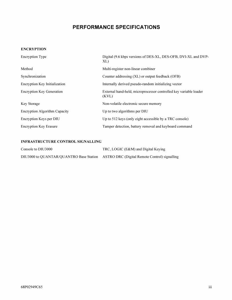
PERFORMANCE SPECIFICATIONS
ENCRYPTION
Encryption Type Digital (9.6 kbps versions of DES-XL, DES-OFB, DVI-XL and DVP-
XL)
Method Multi-register non-linear combiner
Synchronization Counter addressing (XL) or output feedback (OFB)
Encryption Key Initialization Internally derived pseudo-random initializing vector
Encryption Key Generation External hand-held, microprocessor controlled key variable loader
(KVL)
Key Storage Non-volatile electronic secure memory
Encryption Algorithm Capacity Up to two algorithms per DIU
Encryption Keys per DIU Up to 512 keys (only eight accessible by a TRC console)
Encryption Key Erasure Tamper detection, battery removal and keyboard command
INFRASTRUCTURE CONTROL SIGNALLING
Console to DIU3000 TRC, LOGIC (E&M) and Digital Keying
DIU3000 to QUANTAR/QUANTRO Base Station ASTRO DRC (Digital Remote Control) signalling
68P02949C65 iii
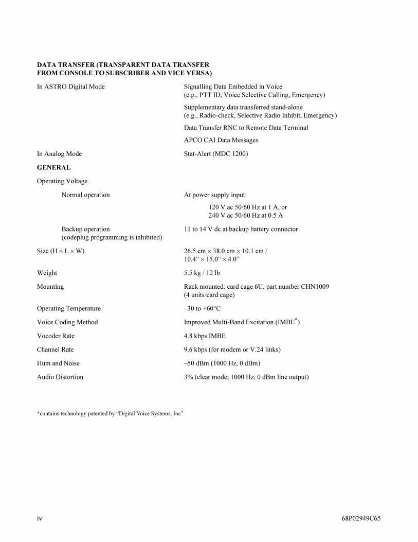
DATA TRANSFER (TRANSPARENT DATA TRANSFER
FROM CONSOLE TO SUBSCRIBER AND VICE VERSA)
In ASTRO Digital Mode Signalling Data Embedded in Voice
(e.g., PTT ID, Voice Selective Calling, Emergency)
Supplementary data transferred stand-alone
(e.g., Radio-check, Selective Radio Inhibit, Emergency)
Data Transfer RNC to Remote Data Terminal
APCO CAI Data Messages
In Analog Mode Stat-Alert (MDC 1200)
GENERAL
Operating Voltage
Normal operation At power supply input:
120 V ac 50/60 Hz at 1 A, or
240 V ac 50/60 Hz at 0.5 A
Backup operation
(codeplug programming is inhibited)
11 to 14 V dc at backup battery connector
Size (H � L � W) 26.5 cm � 38.0 cm � 10.1 cm /
10.4” ��15.0”���4.0”
Weight 5.5 kg / 12 lb
Mounting Rack mounted: card cage 6U, part number CHN1009
(4 units/card cage)
Operating Temperature –30 to +60°C
Voice Coding Method Improved Multi-Band Excitation (IMBE*)
Vocoder Rate 4.8 kbps IMBE
Channel Rate 9.6 kbps (for modem or V.24 links)
Hum and Noise –50 dBm (1000 Hz, 0 dBm)
Audio Distortion 3% (clear mode; 1000 Hz, 0 dBm line output)
*contains technology patented by “Digital Voice Systems, Inc”
iv 68P02949C65

CONSOLE WIRELINE INTERFACE
Line Type 4–wire, 600 � balanced output.
TRC Function Tone Sensitivity –25 dBm W/L Board version A and B
–20 dBm W/L Board version C with JU7 IN
AGC Input Knee –30 dBm 1 KHz tone, W/L Board version A and B
–12 dBm 1 KHz tone, W/L Board version C with JU7 IN
Output to Console Adjustable, maximum 0 dBm into 600 �
BASE STATION WIRELINE INTERFACE
Line Type 4–wire, 600 � balanced output.
For best modem performance, private line or 3002 channel with C5
conditioning is recommended.
Modem Input Sensitivity –5 dBm to –25 dBm
AGC Input Knee –30 dBm 1 KHz tone, W/L Board version A and B
–12 dBm 1 KHz tone, W/L Board version C with JU7 IN
Output to Base Station Adjustable, maximum 0 dBm into 600 �
68P02949C65 v
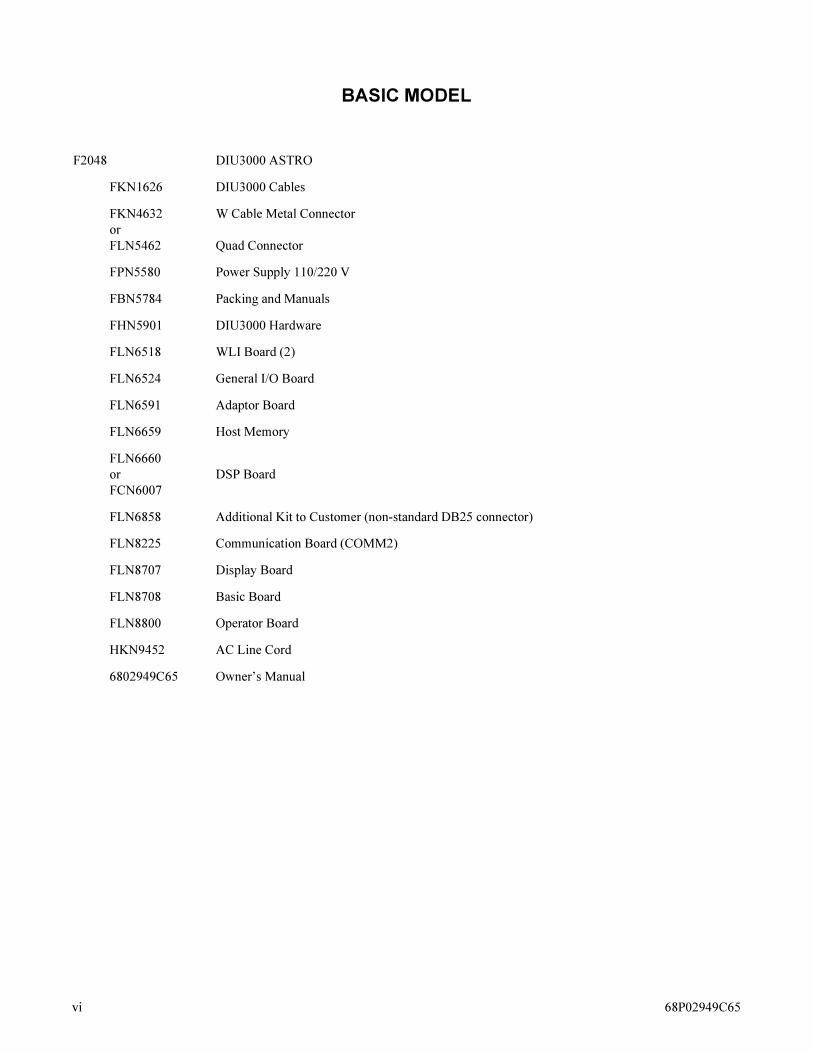
BASIC MODEL
F2048 DIU3000 ASTRO
FKN1626 DIU3000 Cables
FKN4632
or
FLN5462
W Cable Metal Connector
Quad Connector
FPN5580 Power Supply 110/220 V
FBN5784 Packing and Manuals
FHN5901 DIU3000 Hardware
FLN6518 WLI Board (2)
FLN6524 General I/O Board
FLN6591 Adaptor Board
FLN6659 Host Memory
FLN6660
or
FCN6007
DSP Board
FLN6858 Additional Kit to Customer (non-standard DB25 connector)
FLN8225 Communication Board (COMM2)
FLN8707 Display Board
FLN8708 Basic Board
FLN8800 Operator Board
HKN9452 AC Line Cord
6802949C65 Owner’s Manual
vi 68P02949C65
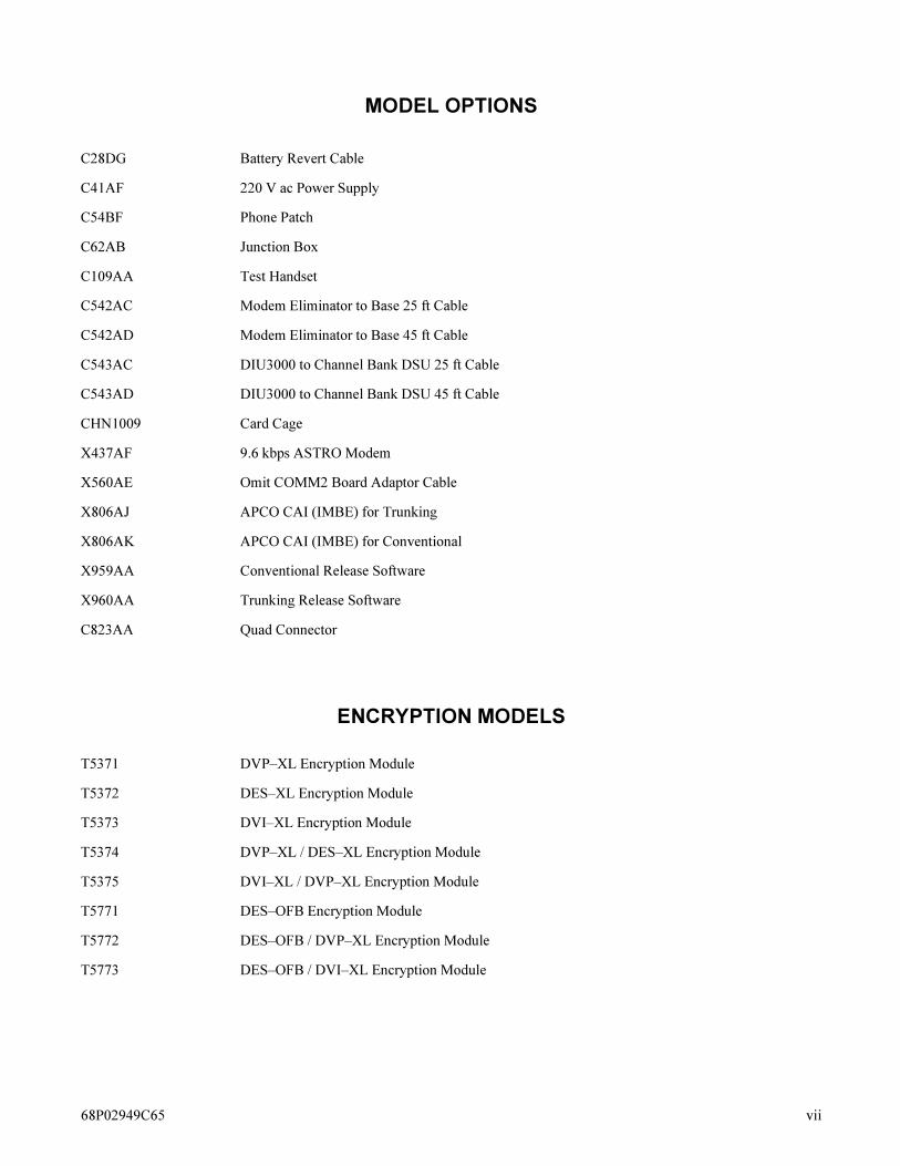
MODEL OPTIONS
ENCRYPTION MODELS
C28DG Battery Revert Cable
C41AF 220 V ac Power Supply
C54BF Phone Patch
C62AB Junction Box
C109AA Test Handset
C542AC Modem Eliminator to Base 25 ft Cable
C542AD Modem Eliminator to Base 45 ft Cable
C543AC DIU3000 to Channel Bank DSU 25 ft Cable
C543AD DIU3000 to Channel Bank DSU 45 ft Cable
CHN1009 Card Cage
X437AF 9.6 kbps ASTRO Modem
X560AE Omit COMM2 Board Adaptor Cable
X806AJ APCO CAI (IMBE) for Trunking
X806AK APCO CAI (IMBE) for Conventional
X959AA Conventional Release Software
X960AA Trunking Release Software
C823AA Quad Connector
T5371 DVP–XL Encryption Module
T5372 DES–XL Encryption Module
T5373 DVI–XL Encryption Module
T5374 DVP–XL / DES–XL Encryption Module
T5375 DVI–XL / DVP–XL Encryption Module
T5771 DES–OFB Encryption Module
T5772 DES–OFB / DVP–XL Encryption Module
T5773 DES–OFB / DVI–XL Encryption Module
68P02949C65 vii
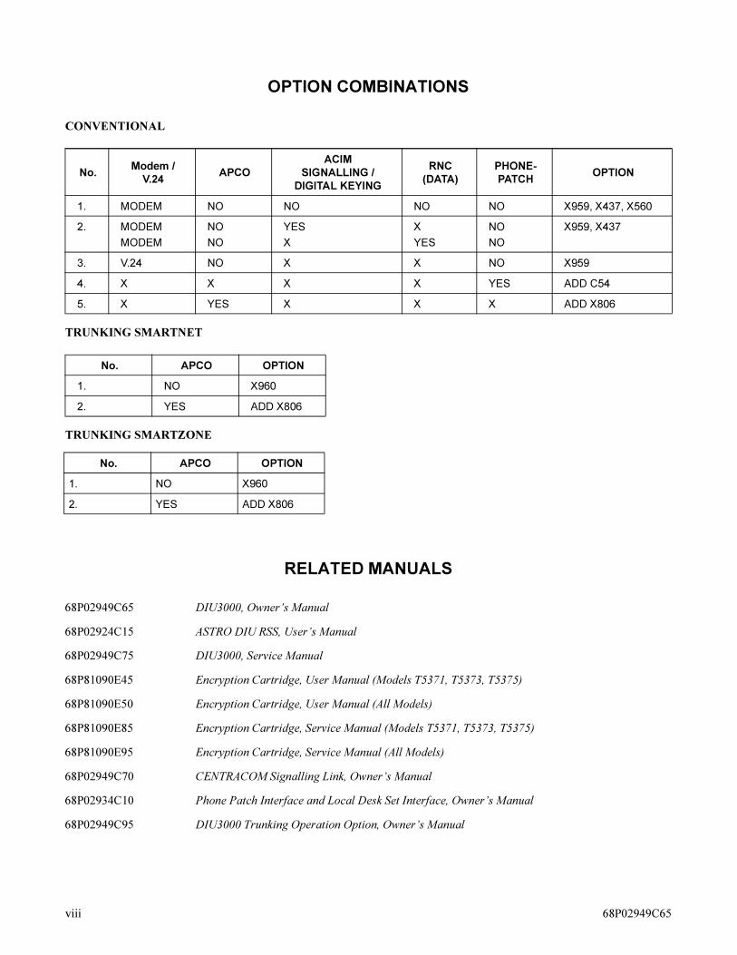
OPTION COMBINATIONS
CONVENTIONAL
TRUNKING SMARTNET
TRUNKING SMARTZONE
RELATED MANUALS
No.Modem /
V.24APCO
ACIM
SIGNALLING /
DIGITAL KEYING
RNC
(DATA)
PHONE-
PATCHOPTION
1. MODEM NO NO NO NO X959, X437, X560
2. MODEM
MODEM
NO
NO
YES
X
X
YES
NO
NO
X959, X437
3. V.24 NO X X NO X959
4. X X X X YES ADD C54
5. X YES X X X ADD X806
No. APCO OPTION
1. NO X960
2. YES ADD X806
No. APCO OPTION
1. NO X960
2. YES ADD X806
68P02949C65 DIU3000, Owner’s Manual
68P02924C15 ASTRO DIU RSS, User’s Manual
68P02949C75 DIU3000, Service Manual
68P81090E45 Encryption Cartridge, User Manual (Models T5371, T5373, T5375)
68P81090E50 Encryption Cartridge, User Manual (All Models)
68P81090E85 Encryption Cartridge, Service Manual (Models T5371, T5373, T5375)
68P81090E95 Encryption Cartridge, Service Manual (All Models)
68P02949C70 CENTRACOM Signalling Link, Owner’s Manual
68P02934C10 Phone Patch Interface and Local Desk Set Interface, Owner’s Manual
68P02949C95 DIU3000 Trunking Operation Option, Owner’s Manual
viii 68P02949C65

Description 1
Description
ASTRO System Overview
General
Modern two–way communication demands secure communication, data
signalling, and higher quality voice transfer. With these goals in mind, ASTRO
system designers have developed a system, based on digitized voice, that
successfully answers these three needs.
The main features of the ASTRO system are:
• Enhanced digital audio quality
• Expanded signalling capabilities
• More efficient use of the existing RF spectrum
• Expanded encryption capabilities
• Integrated voice and data
In addition, the ASTRO system allows the use of the existing analog subscribers,
concurrently with the new ASTRO subscribers, thus creating a smooth migration
from the existing analog two–way environment, to the new, digital ASTRO
environment.
ASTRO System Technologies
Voice Digitizing
Voice digitizing is performed using the IMBE (Improved Multi–Band Excitation)
technique, if option X806 is installed. These techniques provide high–quality
audio on 12.5 kHz bandwidth channels.
Usage of the RF Spectrum
Efficient use of the existing RF spectrum is achieved by using 12.5 kHz
bandwidth channels for both analog and ASTRO communications. The ASTRO
equipment can also be used on the 25 kHz channels, for backward compatibility.
Encryption
ASTRO systems utilize the same IC–based digital encryption algorithms used in
SECURENET systems. These are linear functions that operate bit–by–bit and are
governed by the selection of an encryption key variable.
However, the ASTRO digital technology introduces several enhancements,
previously unavailable in encrypted voice radio systems, as follows:
• There is no range degradation in the encrypted mode, regardless of the
algorithm employed.
2 ASTRO DIU Owner’s Manual
• There is no voice truncation at the beginning of the voice message.
• Multiple algorithm capability.
• Support of the Over–the–Air-Rekeying (OTAR) future option.
Error Protection
The error protection required by a high quality communication system is achieved
by using a variety of forward error correcting methods, to protect the various
fields of the digital transmission against noise interferences. In addition, the
modulation scheme adopted for the over–the–air transmission is the Compatible
Four Level Frequency Modulation, which provides reduced probability of error
for a given signal strength.
Data in the ASTRO System
ASTRO systems transmit data in three ways:
• Data embedded in voice, used for the following purposes:
– To control the base station/repeater/comparator, and the DIU3000 during the
voice communication.
– To provide encryption information (synchronization, key).
– To convey information related to the system users that communicate with
each other (source/destination ID, talkgroup ID, voice selective calling,
emergency, transmit power level, received signal quality, etc.).
• Supplementary data, sent when no voice communication is in progress, and
used for supervisory, control purposes and pure data transmission.
• APCO CAI data transmission to/from the Host computer (via the RNC) and
remote data terminals.
Tone Remote Control
The DIU3000 control by an analog console (Centracom Series II or T5600) is
made possible by the DIU3000 capability to decode Tone Remote Control
sequences.
ASTRO System Building Blocks
The following are the main building blocks of an ASTRO system:
• ASTRO field radios:
– ASTRO Digital SABER: A fully digital portable radio available in three
different models of variable radio complexities.
– ASTRO Digital SPECTRA: A fully digital mobile radio that can be
physically configured as per customer application.
• ASTRO infrastructure devices:
– Quantar (VHF band), Quantro (UHF and 800 MHz bands): A fully digital
station. Both versions are ASTRO–transparent; no voice processing takes

Description 3
place in either. However, digital signal error correction is performed on all
received digital ASTRO signals.
– ASTRO satellite receivers: Consist of the same components as the base
station, but without the transmitting capability.
– ASTRO comparator: A fully digital signal voter which can vote both on
ASTRO digital signals and on analog signals, and provides the ASTRO
systems with the ability to obtain wide area coverage.
– ASTRO DIU3000 Digital Interface Unit, which interfaces analog consoles to
ASTRO radio infrastructures (discussed in detail throughout the rest of this
manual).
– ASTRO control equipment: Centracom Series II, T5600 series, and any other
Tone Remote Control capable console, RNC3000 and MRTI2000.
• ASTRO encryption support devices:
– Key Variable Loader (KVL): A hand–held device that distributes the
encryption key variables to field units and DIUs.
– Key Management Facility (KMF): A facility that serves as a centralized
encryption key manager to remotely distribute encryption keys over the air.
4 ASTRO DIU Owner’s Manual
A Sample ASTRO System
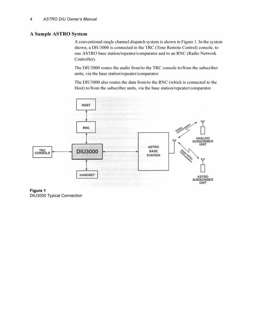
A conventional single channel dispatch system is shown in Figure 1. In the system
shown, a DIU3000 is connected to the TRC (Tone Remote Control) console, to
one ASTRO base station/repeater/comparator and to an RNC (Radio Network
Controller).
The DIU3000 routes the audio from/to the TRC console to/from the subscriber
units, via the base station/repeater/comparator.
The DIU3000 also routes the data from/to the RNC (which is connected to the
Host) to/from the subscriber units, via the base station/repeater/comparator.
.
Figure 1
DIU3000 Typical Connection
Description 5
Digital Interface Unit
General
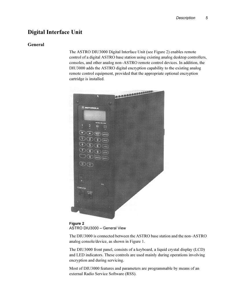
The ASTRO DIU3000 Digital Interface Unit (see Figure 2) enables remote
control of a digital ASTRO base station using existing analog desktop controllers,
consoles, and other analog non–ASTRO remote control devices. In addition, the
DIU3000 adds the ASTRO digital encryption capability to the existing analog
remote control equipment, provided that the appropriate optional encryption
cartridge is installed.
.
The DIU3000 is connected between the ASTRO base station and the non–ASTRO
analog console/device, as shown in Figure 1.
The DIU3000 front panel, consists of a keyboard, a liquid crystal display (LCD)
and LED indicators. These controls are used mainly during operations involving
encryption and during servicing.
Most of DIU3000 features and parameters are programmable by means of an
external Radio Service Software (RSS).
Figure 2
ASTRO DIU3000 – General View

6 ASTRO DIU Owner’s Manual
DIU3000 Features
• Multi–Mode Operation. The DIU3000 can operate in the clear (non–
encrypted) analog, clear ASTRO digital, and the optional encrypted ASTRO
digital modes, providing backward compatibility with existing analog
equipment. The DIU3000 provides seamless transitioning between different
types of calls by automatically switching to match the mode of each.
• Full Duplex Operation. The DIU3000 is capable of handling inbound and
outbound signals simultaneously.
• Integrated Modem. A digital modem that provides access to ASTRO digital
fixed equipment is optionally integrated into the DIU3000, saving valuable site
space.
• Encryption Capability. The Encryption Cartridge options provide the
DIU3000 with encryption capability.
Single– or Dual–algorithm models are available, all operating at 9.6 kbps. The
dual–algorithm feature allows organizations using different encryption
algorithms to interoperate in the secure mode.
All encryption types provide the same high level of security as the Motorola
SECURENET systems, but the ASTRO technology provides better audio
quality – there is no quality degradation due to range and no voice truncation in
the beginning of the message.
• Multikey Capability. Up to 512 encryption keys can be selected by a TRC
console position. Up to 512 keys can be selected by a Digital Keying Console
(DKC). These keys are used to encode outbound calls from the console.
Inbound transmissions from a subscriber are decoded with the key specified in
the received message. This capability provides the flexibility to configure your
system to interoperate securely with several user groups using different
encryption keys.
• Compliance with FIPS 140–1 Security Requirements. The DIU3000 can be
programmed by the RSS to restrict access to encryption/decryption services in
compliance with the FIPS 140–1 security requirements.
• Alert Tones. When an encryption option is installed and the alert option is
enabled via the RSS, the DIU3000 alerts the console operator if there is key
failure or when the operator tries to transmit in the clear mode.
• Keyboard and LCD. The DIU3000 is provided with a keyboard and an LCD
that greatly facilitate installation and maintenance operations.
• Handset Support. The optional Handset facilitates installation and
maintenance operations. The handset allows maintenance personnel to monitor
incoming calls and perform test transmissions.
• AC Battery Backup Interface. The DIU3000 supports the use of an external
battery as a backup for the ac power supply.
• Centracom Digital Link Interface. The Centracom Digital Link Interface is
supplied with the basic model and, in conjunction with the ACIM (ASTRO
Description 7
Console Interface Module) installed in the Centracom, enables the Centracom
analog console to use ASTRO signalling (such as PTT ID, Radio Check, etc.).
Console transmission can also be controlled by a digital keying console. In this
case, the console uses the digital ACIM path to send commands such as “key up
the Base Station" to the DIU3000. The protocol on this interface supports all the
same functionality as supported by TRC. This operation is required for the
SmartNet Trunking System configurations and is optional for conventional
system configurations. Digital keying reduces the console key up time,
eliminates the console dependency on the limited number of tones allowed in its
tone tables and is a more appropriate keying method for a digital radio system.
For additional information, refer to the Centracom Signalling Link Owner’s
Manual.
• Trunking Operation. The DIU3000 Trunking Operation option is required for
integrating the DIU3000 into an ASTRO system provided with SmartZone/
SmartNet capabilities. For additional information, refer to the DIU3000
Trunking Operation option manual (68P02949C95).
• Phone Patch Support. The Phone Patch option allows the connecting of the
MRTI2000 telephone line interface to the DIU3000, for mobile–to–land and
land–to–mobile telephone interconnection. For additional information, refer to
the Phone Patch and Logic Console option manual 68P02934C10.
• Logic (E&M) Console Support. The Logic Console option allows the
connecting of non–TRC consoles to the DIU3000. For additional information,
refer to the Phone Patch and Logic Console option manual 68P02934C10.
• External Terminal Interface. The DIU3000 provides an RS–232 interface that
can be used for connecting a diagnostic printer, a terminal or an RSS running
computer. The interface provides the user with the flexibility to program
DIU3000 parameters, perform in–box diagnostics and retrieve stored diagnostic
information.
• Built–In Test Equipment (BITE). The DIU3000 has an extensive BITE that
performs self–testing at power–on and during operation. Detected failures are
stored in the DIU3000 memory and can either be displayed on the DIU3000
LCD or retrieved via the printer/terminal interface.
• Mounting. The DIU3000 can be mounted in a card cage style 6–U, part number
CHN1009.
8 ASTRO DIU Owner’s Manual
DIU3000 Basic Model and Options
Digital Link to Base Station/Comparator
The DIU3000 Communication board provides a V.24 digital link to the base
station/comparator. The digital link supports only the ASTRO operation modes -
Clear and Encrypted.
The V.24 digital link is limited to indoor use and its physical length should not
exceed 50 feet. To enable long distance digital communication, Channel Bank
DSU is used to interconnect the V.24 digital link to the T1 link.
The Digital Link includes the DIU3000 Communication Adaptor Cable,
FKN4632A. In addition, it is possible to order one of the following cable options:
• Option C542AC - 25 feet long Modem Eliminator to Base Cable
• Option C542AD - 45 feet long Modem Eliminator to Base Cable
• Option C543AC - 25 feet long DIU3000 to Channel Bank DSU Cable
• Option C543AD - 45 feet long DIU3000 to Channel Bank DSU Cable
Centracom Signalling Link
The DIU3000 basic model includes a digital link in addition to the basic analog
link between the DIU3000 and the CENTRACOM console. The digital link
enables the transfer of ASTRO digital signalling information, such as Talk Group
ID, Selective Calling, Emergency Alarm, Radio Check, etc. The digital keying
consoles gain a full benefit from the ACIM link since they allow keying up using
a digital frame.
The CENTRACOM console should include the ACIM module and an additional
cable for interfacing between the ACIM and DIU3000.
The CENTRACOM Signalling Link is covered in detail in manual no.
68P02949C70.
Battery Revert Cable (option C28DG)
This option allows connecting a backup battery to the DIU3000. A 12 V, size–A,
10 Ah battery, should provide backup power for at least five hours in case of ac
power failure. The customer must supply the battery and ensure that it is kept
charged.
.
220 V Primary Power (option C41AF)
Replaces the standard 110 V ac input power supply with the 220 V supply.
If you purchased both the Battery Revert Cable and Junction Box
(C62AB) options, you will have to remove the DB–25 connector from
the battery revert cable and connect the battery via the junction box.Note

Description 9
Junction Box (option C62AB)
The junction box splits the General Purpose I/O (GPIO) board output port
(connector “OPT. 1") on the DIU3000 rear panel into several TBs and thus
facilitates wire connection to the connector (DB–25, female). This option is
especially useful when more than one device should be connected to this general
purpose I/O connector.
The following functions are supported by the GPIO board via the junction box:
• Two hardware indication output lines (RECEIVE UNSQUELCH and MODE
INDICATION) for a Centracom console (see also “Connecting the Hardware
Indications to CENTRACOM (two lines, for CENTRACOM only)” on page
23).
• External battery for power backup (see also “Battery Revert Cable (option
C28DG)” on page 27).
• M–lead digital output indicating transmission from DIU3000 (closed contact to
ground).
Test Handset (option C109A, part number CDN6209)
The test handset complements the DIU3000 features to allow a console–like
operation. Using this option effectively facilitates system testing and
troubleshooting.
DIU3000 Trunking Operation (option X960AA)
This option includes the SmartZone operation and the SmartNet operation.
DIU3000 in SmartZone Operation
In the SmartZone system, the DIU3000 is connected to the Zone Controller and to
the Audio Switch, rather than to being connected directly to the base station and
the console. The DIU3000 serves as a SmartZone system resource for the analog,
ASTRO clear and ASTRO encrypted dispatch and the telephone interconnect.
There are four links connected to the DIU3000 in the SmartZone architecture:
• V.24 digital link to the DSU, used to communicate with the base station over a
T1 link via the Audio Switch.
• Analog four–wire link, used to transfer voice to/from the CENTRACOM
console over a T1 link via the Audio Switch.
• RS–232 communication link to the Multi–Drop Data Broadcast device, used by
the Zone Controller for controlling the DIU3000.
• Analog four-wire link, used to transfer analog voice to/from the base station
over a T1 link via the Audio Switch.
Additional cables (optional) used to connect the Channel Bank DSU (options
C543AC and C543AD) are necessary.
10 ASTRO DIU Owner’s Manual
DIU3000 in SmartNet Operation
In a SmartNet system, the DIU3000 is controlled by the base station commands,
and by a local console. The DIU3000 option described here refers to those DIU
features that enable it to work in a SmartNet system.
There are five links connected to the DIU in the SmartNet architecture:
• V.24 digital link, used to communicate with the base station. Over this link the
DIU receives commands from base station, regarding the transmission
attributes. It is also used to transfer digital audio data to/from the base station.
• Analog 4W link, used to transfer voice to/from the base station.
• Asynchronous RS–232 communication link, used for digital communication
control to/from the console, mainly KEY-UP commands issued by the console.
• Analog 4W link, used to transfer voice to/from the console.
• 2W link, used to transfer voice between the DIU and the Public Switched
Telephone Network. This link physically connects the DIU Patch connector to a
two-to-four wire convertor.
For additional information, refer to the DIU3000 Trunking Operation option,
manual 68P02949C95.
DIU3000 Conventional Operation (option X959AA)
This option is used when no trunking capability is required from the DIU. In
conventional systems the DIU3000 is connected to a console and a base station/
comparator/repeater.
9.6 kbps ASTRO Modem (option X437AF)
This option adds a modem board to the DIU3000, that allows digital voice
communication via an analog link to the base station/comparator/repeater,
providing the capability to connect the DIU3000 far away from the base.
When this option is installed, the full DIU3000 connection capabilities may be
implemented: modem or V.24 links, connection to TRC or digital consoles, as
well as phone patch.
Phone Patch (option C54BF)
This option provides the DIU3000 with the telephone interconnect capability. In
this application, the DIU3000 is connected to the radio–telephone interconnect
equipment (MRTI2000) in addition to its connection to the console and the base
station.
Encryption Cartridge (models T5371, T5372, T5374, T5375, T5771–T5773)
The encryption cartridge adds cryptographic features to the DIU3000. The circuit
components and embedded software, making up the cartridge, are fitted on a

Description 11
printed circuit which is mounted in a cartridge–like housing, designed to be a
removable component in the DIU3000.
Communication QUAD Connector (option C823AA).
This QUAD connector provides an interface connection to the DIU3000, F2048A
COMM connector.
The QUAD connector can be used as an alternative–but not as a direct
replacement–to the W-cable, FKN4632A.
The QUAD connector connects to the BD-25, female COMM connector and
provides access via four RJ45 connectors to the following alternative
infrastructure devices:
• a co-located RNC, Radio Network Controller
• an ACIM/SMARTZONE (jumper selectable)
• a co-located station/comparator
• a remote station/comparator.
ASTRO System Modes of Operation
The DIU3000 supports the following ASTRO system modes of operation:
• Analog
• ASTRO Clear
• ASTRO Encrypted
Figure 3
Quad Connector – General View

12 ASTRO DIU Owner’s Manual
Analog Mode
In the Analog mode, the ASTRO base station communicates with analog
subscriber equipment. In this mode, the DIU3000 transfers the voice to and from
the base station in analog format. Encryption is not supported in the analog mode.
(The ASTRO base station keying command sequences are converted into ASTRO
digital remote control signalling.)
ASTRO Clear Mode
In the ASTRO Clear mode, all communications between the DIU3000 and base
station and between the base station and subscriber equipment are performed in
the ASTRO digital format and all voice messages are not encrypted.
ASTRO Encrypted Mode
In the ASTRO Encrypted mode, all communications between the DIU3000 and
base station and between the base station and subscriber equipment are performed
in the ASTRO digital format and all voice messages are encrypted.
All the encryption and decryption operations are performed by the optional
encryption cartridge installed in the DIU3000. In order to activate a function
involving either encryption/decryption or access an encryption parameter when
FIPS capability is enabled, an encrypted session must be opened. To open an
encrypted session, the operator must login to the module. Login requires entering
a valid password, known only to authorized personnel.
Once an encrypted session has been opened, it is no longer required to login
before additional functions involving encryption should be performed.
The DIU3000 supports separation of responsibilities and duties between several
operators, according to the FIPS 140–1 requirements. The following encryption
related operator roles are supported:
• User. The user can obtain the encryption/decryption services from the
cryptographic module, but cannot access or modify the cryptographic
parameters and management functions.
• Crypto–officer. The crypto–officer is authorized to perform cryptographic
initialization and management functions (such as cryptographic key and
parameter entry).
• Maintenance role. The maintenance operator is authorized to perform tests and
obtain interim results in order to maintain or troubleshoot the cryptographic
module. The module automatically clears all operational keys and other security
parameters when entering the maintenance role. When exiting the maintenance
role, the module automatically clears all maintenance keys and other security
parameters.
Each operator role requires a different password. The DIU3000 prevents opening
concurrent sessions in the same operator role.
Description 13
The operator is required to logout in order to terminate an encrypted session. Once
a logout has been completed, a login is required in order to establish a new
encrypted session.
DIU3000 Functional Description
Interface and Processing Functions
The DIU3000 interfaces analog control equipment to the ASTRO radio systems.
It is a stand alone device connected between a control console and the ASTRO
base station/comparator.
Without the console operator intervention, the DIU3000 performs several
interface and processing functions, described in the following sections.
Voice Processing
In the ASTRO Clear and Encrypted modes, the DIU3000 converts the analog
voice messages from the console or local handset into digital form, and converts
the digital voice from the base station into analog form. The DIU3000, as a part of
the ASTRO system, uses the IMBE (Improved Multi-Band Excitation) technique,
if option X806 is installed, for compressing the digitized voice.
In the analog mode, the DIU3000 transfers the audio between the console and the
base station in the original analog form.
.
Encryption (Optional)
The DIU3000, by means of the encryption cartridge, provides digital encryption
of outbound voice and decryption of inbound voice. Depending on the model
purchased, single– or dual–algorithm operation is supported.
The DIU3000 performs the encryption and decryption operations using
encryption keys. For decryption of received messages, the received key is used.
For encryption of outbound messages, there are two key selection modes,
controlled by the console: Manual and Automatic. In the Manual mode, the
required key is selected by the console operator via a TRC command (see also
section 5.1.6), or a digital keying command. In the AUTO mode, the transmit key
MRTI (analog and digital inbound), Console (analog and digital
inbound) and Base Station (analog outbound) audio levels may be set
in RSS or from the front panel display (after entering service mode,
password: 039302164). Each interface may be changed by 20 dB in
1 dB increments. Because the DIU3000 passes and generates voice
and tones at various levels, there is no absolute output level as
suggested by the term 'dBm' on the front panel display. The term 'dBm'
that accompanies gain settings in RSS and the front panel display
should be interpreted as a rough estimate of signal output. In other
words, the output level display should be thought of as a volume gain
control, not as an absolute level indicator. The exact output, in dBm, is
a function of 1) the source level, 2) the output level setting and 3) the
averaging method used to measure the signal
Note

14 ASTRO DIU Owner’s Manual
is almost exclusively dependent on the received message key. For additional
details on key selection, refer to your Encryption Cartridge manual.
The DIU3000 supports encryption key indexing for mapping encryption key
numbers to actual encryption keys used for ASTRO encrypted transmission. If a
key number is defined as indexed, two actual keys are mapped to that key number
via the key indexes. One of the actual keys is specified by index 1, while the other,
by index 2. The actual key used for transmission is determined according to the
active key index.
The key indexing feature allows the keys in the inactive index to be available for
rekeying. After the inactive key has been rekeyed, the key index can be switched,
but the key number is still unchanged from the user's perspective.
Error Protection
The DIU3000 inserts an error protection code into the digital voice datastream
(both clear and encrypted). This allows the receiving ASTRO subscriber to
correct corrupted messages to the desired level. In the receiving direction, the
DIU3000 uses the same error correction method to detect and correct errors in the
received messages.
Embedded Signalling
ASTRO systems can transfer signalling information by intermixing it with the
digital voice. This type of signalling is referred to as “embedded signalling".
The DIU3000 uses embedded signalling to include the following information in
the transmitted messages:
• Source Unit and Destination Unit IDs, to facilitate selective calling.
• Talkgroup ID, that can be used for sending and receiving selective group calls.
• Encryption Key ID, that is used to inform the receiving ASTRO unit which key
must be used for decryption of the voice message, thus allowing selective
secure calling.
• Additional Encryption Related Information.
Base Station Control
The DIU3000 converts TRC sequences, logic control or digital keying commands
sent by the analog console into ASTRO DRC (Digital Remote Control) signalling.
The DIU3000 controls the following functions in the base station using the DRC
signalling:
• Selection of transmission channel number
• Selection of ASTRO System mode (analog, ASTRO Clear, or ASTRO
Encrypted, see “ASTRO System Modes of Operation” on page 11.)
• Repeater activation/deactivation
• Controlling the second receiver (on/mute)
• Monitor activation/deactivation

Description 15
TRC Command Handling
The DIU3000 converts the TRC command into a combination of ASTRO
commands, referred to as Function REQuests (FREQs). Each TRC function tone
(single– or dual–tone) is converted into a different FREQ. A FREQ may include
up to seven ASTRO Signalling, Base Station control and DIU3000 control
commands. The DIU RSS maintains the TRC FUNCTIONALITY TABLE that
defines the FREQ functions and assigns FREQ numbers to function tones.
Alert Tone Indication
Under certain operating conditions the DIU3000 sends alert tones to the console.
Some of the alert tones can be enabled/disabled via the RSS. The following alert
tones are available:
• Power–on.
• Power–on self–test failure.
• Completion of key loading from KVL. Different alert tones indicate either
loading success or failure.
• Transmission or reception in either analog or ASTRO clear mode (this alert
tone can be disabled by the RSS).
• Absence of a key required for encryption/decryption (this alert tone can be
disabled by the RSS).
• Intentional zeroization of all encryption keys (this alert tone can be disabled by
the RSS).
Local Operation
There are several functions, that can/should be performed by the DIU3000
operator via the DIU3000 front panel, as follows:
• Controlling encryption/decryption services. When the appropriate parameter
is enabled by the RSS, using the ASTRO encryption and decryption services is
restricted, and requires initiating an encrypted session. This is done from the
DIU3000 using the LOGIN function.
• Encryption key erasure. The DIU3000 can be used for erasing the encryption
keys currently programmed into the encryption module memory.
• Controlling Local Transmission Parameters. The DIU3000 front panel is
used to change/view the local PTT/handset transmission parameters.
• Activity monitoring. The DIU3000 can be used for monitoring system
transmit/receive parameters.
• Monitor. The DIU3000 can be used to unsquelch the base station receiver and
monitor the receive path.
• Built–In Test Equipment (BITE). The DIU3000 has an extensive BITE that
performs self–testing at power–on and during operation. Detected failures are
stored in the DIU3000 memory and can either be displayed on the DIU3000
LCD or retrieved via the printer/terminal interface.

16 ASTRO DIU Owner’s Manual
Installation Instructions
General
This chapter provides the DIU3000 installation and setup instructions. It is
suggested to perform the instructions sequentially, skipping those that do not
apply to your site. Following are the general steps:
• Initial inspection
• Planning the installation
• Mounting the unit
• Electrical connections
• Setup
Initial Inspection
As soon as possible after delivery, inspect the shipping package for signs of rough
handling. Unpack the DIU3000 and inspect it thoroughly. If damage was incurred
in transit, notify the transportation company immediately.
Planning the Installation
The DIU3000 interfaces between an analog console and the ASTRO base station
and it is therefore placed on the link between the console and the base. It is
recommended that the DIU3000 be located at the analog console site.
Choose a location that minimizes detrimental environment characteristics, such as
excessive heat, moisture, vibration, sunlight and dust.
Ensure convenient access to an AC power source, base station wire lines,
keyboard, display and handset (if installed), and a good earth ground. Cabling
must have a sufficient length to prevent stress on unanchored connectors. Use
strain relief.
The DIU3000 uses a 4–wire configuration – two pairs of two wires to the base
station and two pairs of two wires to the analog console. If the analog console is a
Centracom type, three additional unbalanced wires for the Mode and Receiver
Unsquelch indications are required (refer also to Figure 9).
The DIU3000 is especially designed for easy installation. A standard installation
does not require opening the DIU3000 housing. Rather, all adjustments are carried
out via an external PC using the ASTRO DIU Radio Service Software (RSS) and
via the DIU3000 keypad.
This chapter provides information for mounting the DIU3000 equipment (see
page 17) and making the necessary electrical connections (see page 20). In
addition, the DIU3000 programmable parameters usually have to be customized
Installation Instructions 17
for the particular site. The programming is done mainly via RSS (refer to the
ASTRO DIU RSS User's manual 68P02924C15). Some of the frequently used
parameters are also programmable via the DIU3000 front panel.
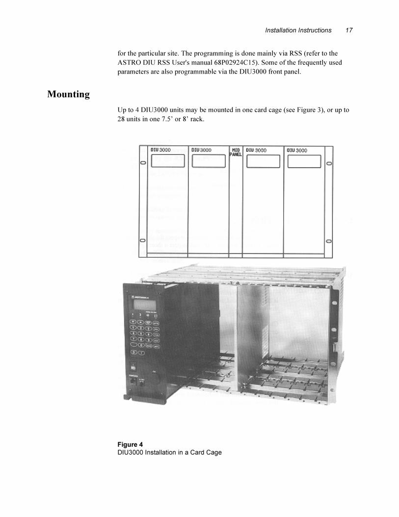
Mounting
Up to 4 DIU3000 units may be mounted in one card cage (see Figure 3), or up to
28 units in one 7.5’ or 8’ rack.
.
Figure 4
DIU3000 Installation in a Card Cage
18 ASTRO DIU Owner’s Manual
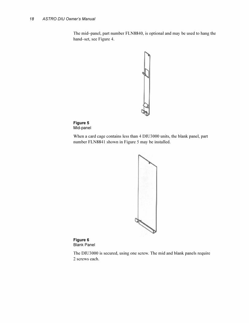
The mid–panel, part number FLN8840, is optional and may be used to hang the
hand–set, see Figure 4.
.
When a card cage contains less than 4 DIU3000 units, the blank panel, part
number FLN8841 shown in Figure 5 may be installed.
.
The DIU3000 is secured, using one screw. The mid and blank panels require
2 screws each.
Figure 5
Mid-panel
Figure 6
Blank Panel
Installation Instructions 19
Installing Encryption Cartridge.
1. Unscrew the four screws fastening the front panel and remove it.
2. Insert the encryption cartridge into its slot.
3. Return the front panel to its place.
.
This section provides the procedure for installing the encryption
cartridge when the DIU3000 is already installed in the card–cage.
To remove the encryption cartridge, it is necessary to use a tool
supplied to the DIU3000 service shops, Motorola part number
6686064C01.
Note
Note

20 ASTRO DIU Owner’s Manual
Electrical Connections
(See Figure 6 and Figure 7)
General
This section describes the various connections between the DIU3000 and other
devices: analog link to console, analog link to base station/repeater/comparator,
digital link (V.24) to base station/repeater/comparator, hardware indications to
CENTRACOM, connection to computer, test handset.
.
Figure 7
DIU3000 Rear Panel
Installation Instructions 21
.
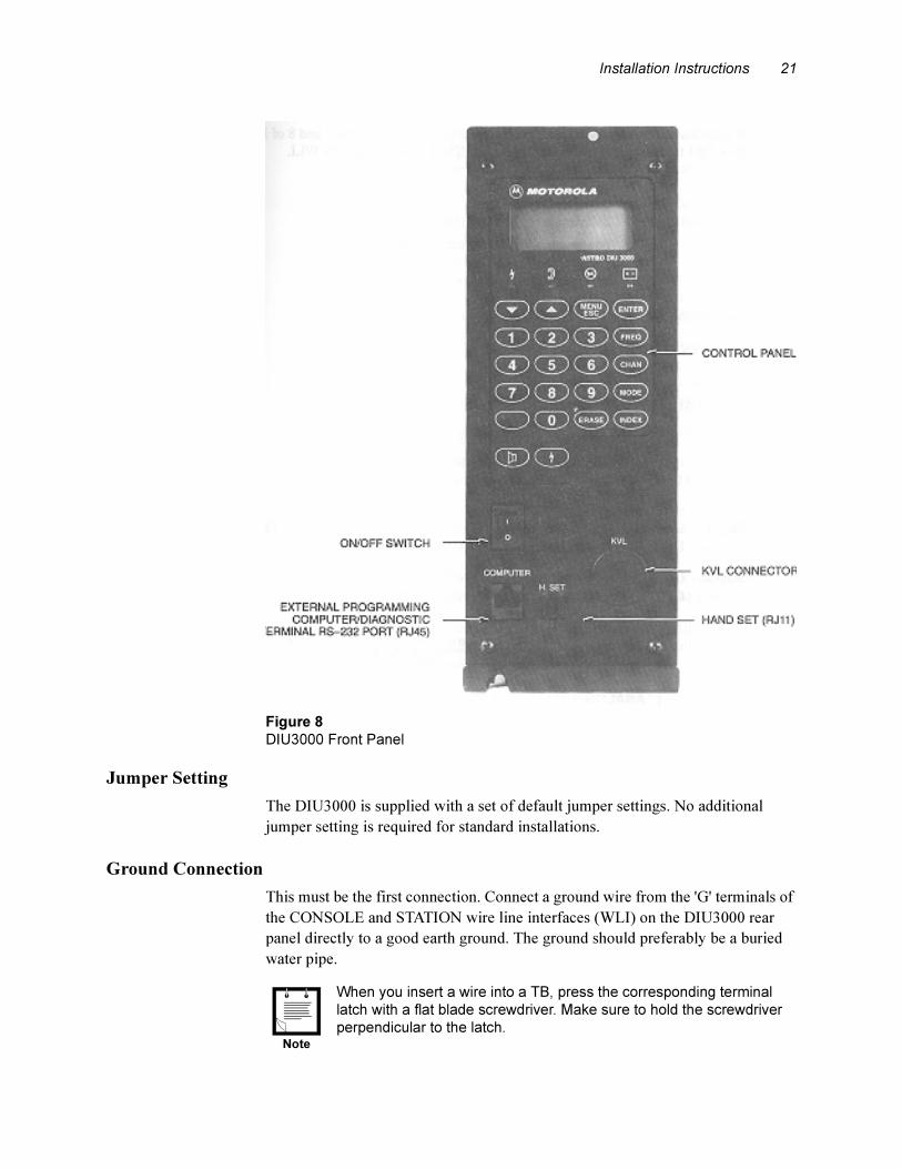
Jumper Setting
The DIU3000 is supplied with a set of default jumper settings. No additional
jumper setting is required for standard installations.
Ground Connection
This must be the first connection. Connect a ground wire from the 'G' terminals of
the CONSOLE and STATION wire line interfaces (WLI) on the DIU3000 rear
panel directly to a good earth ground. The ground should preferably be a buried
water pipe.
.
Figure 8
DIU3000 Front Panel
When you insert a wire into a TB, press the corresponding terminal
latch with a flat blade screwdriver. Make sure to hold the screwdriver
perpendicular to the latch.Note
22 ASTRO DIU Owner’s Manual
If your installation includes Junction Box (optional), connect pins 7 and 8 of
Junction Box TB4 to the same earth ground as the CONSOLE and STATION
WLI.
AC Power.
Connect the AC cable to the LINE plug on the DIU3000 rear panel.
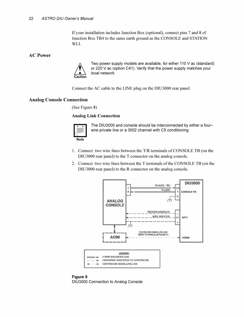
Analog Console Connection
(See Figure 8)
Analog Link Connection
.
1. Connect two wire lines between the T/R terminals of CONSOLE TB (on the
DIU3000 rear panel) to the T connector on the analog console.
2. Connect two wire lines between the T terminals of the CONSOLE TB (on the
DIU3000 rear panel) to the R connector on the analog console.
.
Two power supply models are available, for either 110 V ac (standard)
or 220 V ac (option C41). Verify that the power supply matches your
local network.!Caution
The DIU3000 and console should be interconnected by either a four–
wire private line or a 3002 channel with C5 conditioning.
Figure 9
DIU3000 Connection to Analog Console
Note
Installation Instructions 23
Connecting the Hardware Indications to CENTRACOM (two lines, for
CENTRACOM only)
(See also “Junction Box (option C62AB)” on page 9.)
The connection of the hardware indications to the CENTRACOM console should
only be indoors. The total recommended length of these lines is 1000 feet. The
connector type is DB–25 female.
.
1. If the Junction Box is used, skip this step.
Prepare the cable for the hardware indication signal connections by soldering
three wires to pins 1, 4 and 21 of the DB–25 male connector.
2. Connect the DB–25 male connector of the Hardware indications cable
(prepared in the previous step) or the Junction Box flat cable connector to the
OPT.1 connector on the DIU3000 rear panel.
3. Connect pin 4 (Ground) of the DB-25 connector or TB4-3 on the Junction Box
(if installed) to the CENTRACOM console ground.
4. Connect pin 1 (RECEIVER UNSQUELCH) of the DB-25 connector or TB4-2
on the Junction Box (if installed) to the corresponding pin in the
CENTRACOM console.
5. Connect pin 21 (MODE INDICATION) of the DB-25 connector or TB4-1 on
the Junction Box (if installed) to the corresponding pin on the CENTRACOM
console.
.
Connecting the CENTRACOM Signalling Link
Refer to the CENTRACOM Signalling Link manual, part no. 68P02949C70.
Connecting the E&M Console
Refer to Phone Patch Interface and Local Desk Set Interface, Owner’s manual,
part no. 68P02934C10.
The standard DB–25 connector does not fit into the DIU3000 “OPT1"
connector. Use the DB–25 connector supplied in kit FLN6858A.
The wires used for connecting the hardware indications lines should be
supplied by the customer, according to the specific installation
requirements.
It is recommended to use rigid wires for connection to the TB. In most
cases, soldering the wire tip is a good practice.
Notes
Note
24 ASTRO DIU Owner’s Manual
Base Station/Comparator Connection
General
The DIU3000 can be connected to the base station/comparator using several
methods. They are as follows:
• Via a wire line analog link that uses the internal modem (option X437AF) to
support the ASTRO modes of operation (clear/encrypted).
• Via a digital V.24 link. This link supports the ASTRO modes of operation only
and is limited to indoor use (up to 50 feet long).
• Via both the V.24 link and the wire line link. The V.24 link supports the
ASTRO modes of operation, while the wire line provides the analog mode
support. Since the V.24 link is used, this configuration is limited to indoor use,
as well.
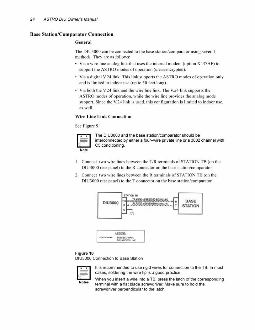
Wire Line Link Connection
See Figure 9.
.
1. Connect two wire lines between the T/R terminals of STATION TB (on the
DIU3000 rear panel) to the R connector on the base station/comparator.
2. Connect two wire lines between the R terminals of STATION TB (on the
DIU3000 rear panel) to the T connector on the base station/comparator.
.
.
The DIU3000 and the base station/comparator should be
interconnected by either a four–wire private line or a 3002 channel with
C5 conditioning.
Figure 10
DIU3000 Connection to Base Station
It is recommended to use rigid wires for connection to the TB. In most
cases, soldering the wire tip is a good practice.
When you insert a wire into a TB, press the latch of the corresponding
terminal with a flat blade screwdriver. Make sure to hold the
screwdriver perpendicular to the latch.
Note
Notes
Installation Instructions 25
Digital Link to Base Station/Channel Bank DSU Connections
.
General
The DIU3000 can be connected to the base station/comparator via the following
digital links:
• W–Cable V.24 (modem eliminator) link, limited to indoor use.
• W–Cable V.24 interconnected to T1 carrier via the Channel Bank DSU.
• QUAD connector V.24
• QUAD connector Null connection.
DIU3000–to–Base Modem Eliminator Connection Procedure
(See Figure 10)
Connecting the digital link to the base station/comparator requires the use of
adaptor cable FKN4632A (W cable), and an additional communication cable. The
additional cable may be ordered as the DIU3000 to Base Modem Eliminator
option C542AC or C542AD (25 ft / 45 ft, respectively) or prepared by the
customer according to Appendix B.
1. Connect the common connector of the adaptor cable, supplied with the option,
to the COMM connector on the DIU3000 rear panel.
2. Connect the DIU3000–to–base modem eliminator cable's female connector to
the DIU3000 communication adaptor cable's male (BASE) connector.
3. Connect the DIU3000–to–base modem eliminator cable to the base station/
comparator.
To use the digital link to base station, the Communication board should
be installed in the DIU3000. The basic model is supplied with the board
installed (FLN8255A).
Connect the W cable (FKN4632A) or QUAD Connector (FLN5462A) to
the COMM port. Do not connect a Y cable (FKN4119A) which was
used with the previous Communication board (FLN6799A). This model
has been discontinued.
Notes
26 ASTRO DIU Owner’s Manual
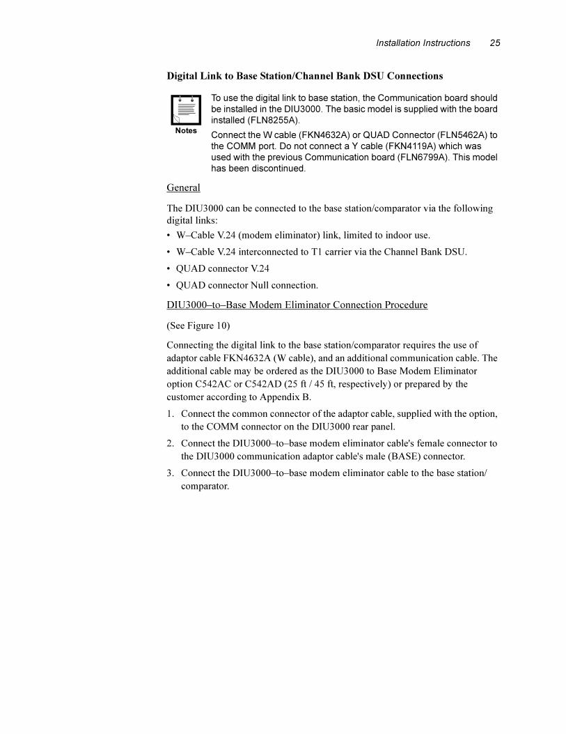
.
DIU3000 to Channel Bank DSU Interconnection Procedure
(See Figure 11).
The digital link that uses the V.24 link is limited to indoor use; long distance
digital interconnection to the base station/comparator can be achieved via the T1
carrier. This connection requires the use of the W adaptor cable (FKN4632A) and
an additional communication cable. The additional cable may be ordered as the
DIU3000 to Channel Bank DSU cable option C543AC or C543AD (25 ft / 45 ft,
respectively) or prepared by the customer according to Appendix B.
.
1. Connect the W adaptor cable's common connector, supplied with the option, to
the COMM connector on the DIU3000 rear panel.
2. Connect the DIU3000–to–Channel Bank DSU cable's female connector to the
DIU3000 communication adaptor cable's male (BASE) connector.
3. Connect the DIU3000–to–Channel Bank DSU cable to the Channel Bank
DSU.
DIU3000 QUAD Connector
DIU connection to a base station or Astrotac comparator can be achieved through
the DIU QUAD connector. The Null connection is designed for connecting
directly to a station or comparator. The V.24 connection is designed for
connection through a channel bank DSU. This connector allows standard telco 8
wire cable to be used with standard RJ45 connectors. Refer to Table 43 on
page 86 for the QUAD connector pin-outs and to Table 44 on page 87 for the
Jumper Settings.
Figure 11
DIU3000 to Base/Channel Bank DSU Digital Link Connections
Using the DIU3000 to Channel Bank DSU interconnection requires
setting the Tx Clock Source parameter value to “EXTERNAL" (Change/
View:Base Station screen in the DIU3000 RSS).Note

Installation Instructions 27
Computer/Diagnostic Terminal
Use the COMPUTER connector (RJ45) on the DIU3000 front panel to connect a
computer or a diagnostic terminal. For detailed instructions on RSS programming,
refer to the DIU RSS User's manual 68P02924C15.
Encryption Cartridge (models T5371, T5372, T5374, T5375, T5771 – T5773)
Refer to the appropriate Encryption Cartridge User manual Part No.
68P81090E45/50.
Test Handset (option C109AA)
Connect the handset cable to the “H. SET" connector (RJ11) on the DIU3000
front panel.
Battery Revert Cable (option C28DG)
A 12–14 V lead acid type battery should be used. A size–A, 10 Ah battery should
provide backup for at least five hours in case of ac power failure. The customer
must ensure that the battery is kept charged.
Connect the battery revert cable between the battery (provided by the customer)
and the DIU3000 as follows:
• If the Junction Box is not used:
– Plug in the revert cable into the “OPT1" connector on the DIU3000 rear
panel.
• If the Junction Box is installed:
– Remove the DB–25 connector from the battery revert cable.
– Connect the revert cable positive lead to TB5–6 on the JB.
– Connect the revert cable negative lead to TB5–7 on the JB.
Quad Connector (FLN5462)
The Quad Connector is used to interface the DIU3000 to a Base Station or
Comparator, to an RNC, and to a Centracom Signaling Link. Before securing the
Quad Connector to the “Comm” port of the DIU3000 please refer to Table 43 for
the connector pin description, and Table 44 for jumper placement information.
Connect the Quad Connector to the Comm Port of the DIU3000 and secure it to
the DIU3000 with the screws supplied.
Three ferrite beads are supplied with the DIU3000. These beads impede
electromagnet emissions, EMI, from the DIU3000 and from cables connecting the
DIU3000 to other infrastructure equipment. These beads should be placed on each
cable connected to the Quad Connector. One loop should be placed in the cable
and around the bead. The bead should be placed as close as possible to the Quad
Connector.
28 ASTRO DIU Owner’s Manual
DIU3000 Setup
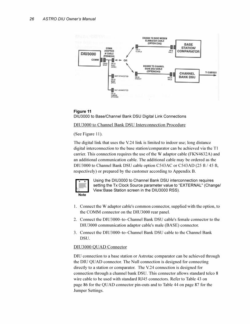
DIU3000 Power–on
After installing the DIU3000, check all wire connections and verify good ground
connection. Connect the ac power and monitor the messages on the DIU3000
display. The following is the sequence of LCD messages during a proper power–
on process:
After the power–on sequence, the DIU3000 tries to establish a link to the base
station using a handshake procedure. During the link establishment, which takes a
few seconds, the BUSY LED is lit. If the link is not connected or the base station
Table 1
Power-on Process Messages
Message Meaning
CHK DB Database checking operations.
PLS WAIT Restoring the parameter database from backup.
NOTE
Usually, this message is too short to notice. However, if this
is the first power–on after downloading new parameters from
the RSS, or if in the previous stage the database was found
corrupted, it is restored (reprogrammed) from the internal
backup. This may take up to five minutes, for the duration of
which the message PLS WAIT is displayed. Upon
successful database programming, the message PROG OK
is displayed shortly. If the DIU3000 fails to restore the
database, an error message is displayed instead of the
PROG OK message. In this case, refer to the
TROUBLESHOOTING section.
LOAD SRV Software server handling.
DSP BOOT Loading DSP processors' software.
SELF TST Checking hardware peripherals.
• During LED tests, all front panel LEDs are lit.
• During LCD tests, all LCD segments are lit in sequence.
• Four tones are heard from the console speaker.
• If the handset option is installed, four tones are heard from
the handset earpiece.
TST PASS The self–test has been successfully completed.
NOTE
If the self test fails, the TST FAIL message is displayed and
an alert tone is sent to the console and to the handset
earpiece.
If this occurs, see the TROUBLESHOOTING section
LOADING Loading application.
HH:MM:SS The clock is displayed.
Installation Instructions 29
is not responding for some other reason, the LED remains lit and the DIU3000
does not allow transmission.
In the ready state, the LCD displays the time of day and the unit is ready for
operation.
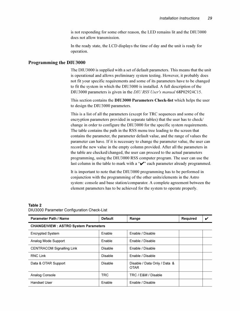
Programming the DIU3000
The DIU3000 is supplied with a set of default parameters. This means that the unit
is operational and allows preliminary system testing. However, it probably does
not fit your specific requirements and some of its parameters have to be changed
to fit the system in which the DIU3000 is installed. A full description of the
DIU3000 parameters is given in the DIU RSS User's manual 68P02924C15.
This section contains the DIU3000 Parameters Check-list which helps the user
to design the DIU3000 parameters.
This is a list of all the parameters (except for TRC sequences and some of the
encryption parameters provided in separate tables) that the user has to check/
change in order to configure the DIU3000 for the specific system requirements.
The table contains the path in the RSS menu tree leading to the screen that
contains the parameter, the parameter default value, and the range of values the
parameter can have. If it is necessary to change the parameter value, the user can
record the new value in the empty column provided. After all the parameters in
the table are checked/changed, the user can proceed to the actual parameters
programming, using the DIU3000 RSS computer program. The user can use the
last column in the table to mark with a “�" each parameter already programmed.
It is important to note that the DIU3000 programming has to be performed in
conjunction with the programming of the other units/elements in the Astro
system: console and base station/comparator. A complete agreement between the
element parameters has to be achieved for the system to operate properly.
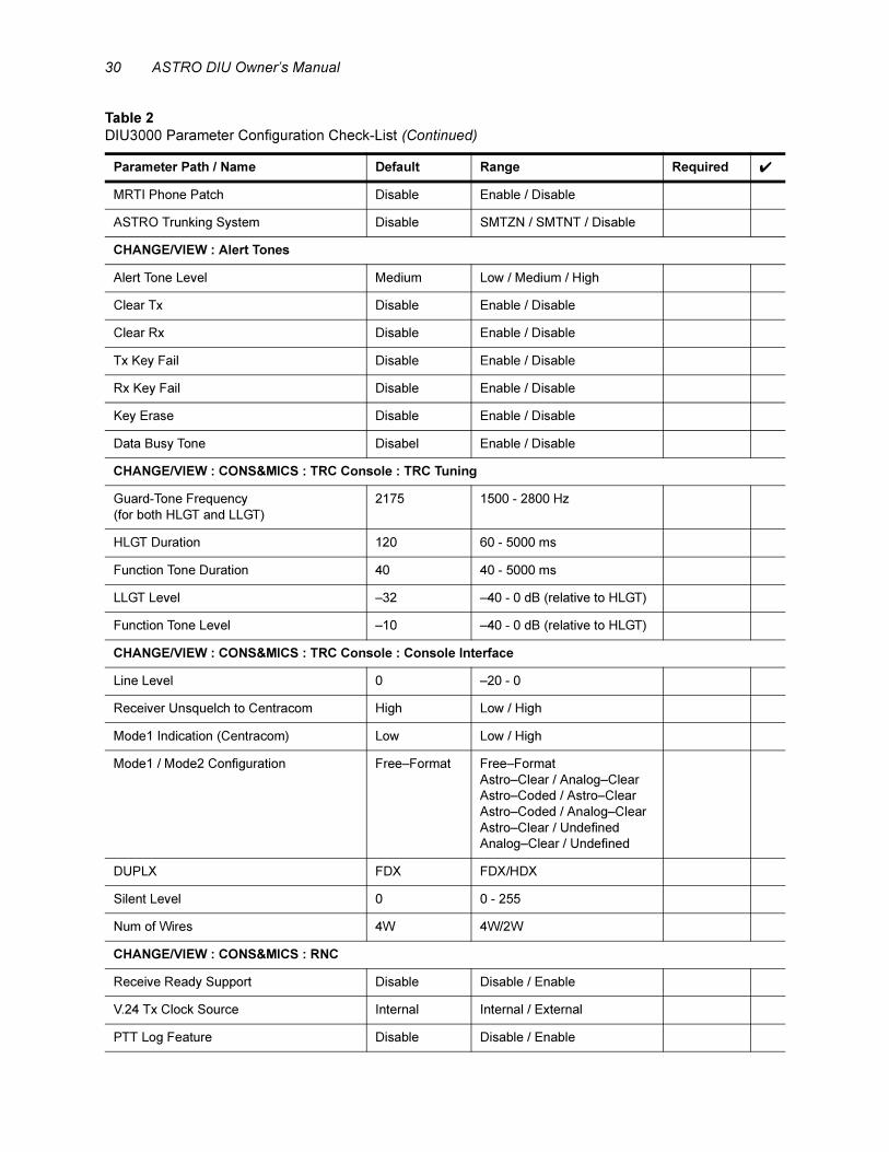
Table 2
DIU3000 Parameter Configuration Check-List
Parameter Path / Name Default Range Required �
CHANGE/VIEW : ASTRO System Parameters
Encrypted System Enable Enable / Disable
Analog Mode Support Enable Enable / Disable
CENTRACOM Signalling Link Disable Enable / Disable
RNC Link Disable Enable / Disable
Data & OTAR Support Disable Disable / Data Only / Data &
OTAR
Analog Console TRC TRC / E&M / Disable
Handset User Enable Enable / Disable
30 ASTRO DIU Owner’s Manual
MRTI Phone Patch Disable Enable / Disable
ASTRO Trunking System Disable SMTZN / SMTNT / Disable
CHANGE/VIEW : Alert Tones
Alert Tone Level Medium Low / Medium / High
Clear Tx Disable Enable / Disable
Clear Rx Disable Enable / Disable
Tx Key Fail Disable Enable / Disable
Rx Key Fail Disable Enable / Disable
Key Erase Disable Enable / Disable
Data Busy Tone Disabel Enable / Disable
CHANGE/VIEW : CONS&MICS : TRC Console : TRC Tuning
Guard-Tone Frequency
(for both HLGT and LLGT)
2175 1500 - 2800 Hz
HLGT Duration 120 60 - 5000 ms
Function Tone Duration 40 40 - 5000 ms
LLGT Level –32 –40 - 0 dB (relative to HLGT)
Function Tone Level –10 –40 - 0 dB (relative to HLGT)
CHANGE/VIEW : CONS&MICS : TRC Console : Console Interface
Line Level 0 –20 - 0
Receiver Unsquelch to Centracom High Low / High
Mode1 Indication (Centracom) Low Low / High
Mode1 / Mode2 Configuration Free–Format Free–Format
Astro–Clear / Analog–Clear
Astro–Coded / Astro–Clear
Astro–Coded / Analog–Clear
Astro–Clear / Undefined
Analog–Clear / Undefined
DUPLX FDX FDX/HDX
Silent Level 0 0 - 255
Num of Wires 4W 4W/2W
CHANGE/VIEW : CONS&MICS : RNC
Receive Ready Support Disable Disable / Enable
V.24 Tx Clock Source Internal Internal / External
PTT Log Feature Disable Disable / Enable
Table 2
DIU3000 Parameter Configuration Check-List (Continued)
Parameter Path / Name Default Range Required �
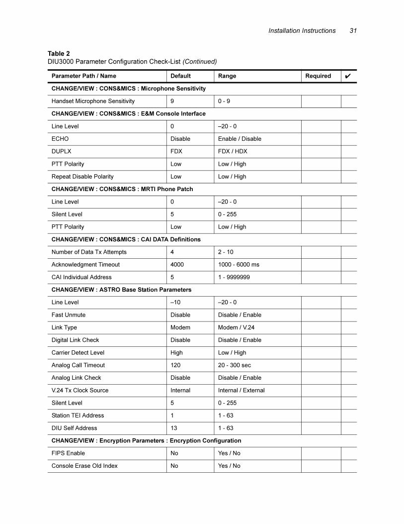
Installation Instructions 31
CHANGE/VIEW : CONS&MICS : Microphone Sensitivity
Handset Microphone Sensitivity 9 0 - 9
CHANGE/VIEW : CONS&MICS : E&M Console Interface
Line Level 0 –20 - 0
ECHO Disable Enable / Disable
DUPLX FDX FDX / HDX
PTT Polarity Low Low / High
Repeat Disable Polarity Low Low / High
CHANGE/VIEW : CONS&MICS : MRTI Phone Patch
Line Level 0 –20 - 0
Silent Level 5 0 - 255
PTT Polarity Low Low / High
CHANGE/VIEW : CONS&MICS : CAI DATA Definitions
Number of Data Tx Attempts 4 2 - 10
Acknowledgment Timeout 4000 1000 - 6000 ms
CAI Individual Address 5 1 - 9999999
CHANGE/VIEW : ASTRO Base Station Parameters
Line Level –10 –20 - 0
Fast Unmute Disable Disable / Enable
Link Type Modem Modem / V.24
Digital Link Check Disable Disable / Enable
Carrier Detect Level High Low / High
Analog Call Timeout 120 20 - 300 sec
Analog Link Check Disable Disable / Enable
V.24 Tx Clock Source Internal Internal / External
Silent Level 5 0 - 255
Station TEI Address 1 1 - 63
DIU Self Address 13 1 - 63
CHANGE/VIEW : Encryption Parameters : Encryption Configuration
FIPS Enable No Yes / No
Console Erase Old Index No Yes / No
Table 2
DIU3000 Parameter Configuration Check-List (Continued)
Parameter Path / Name Default Range Required �
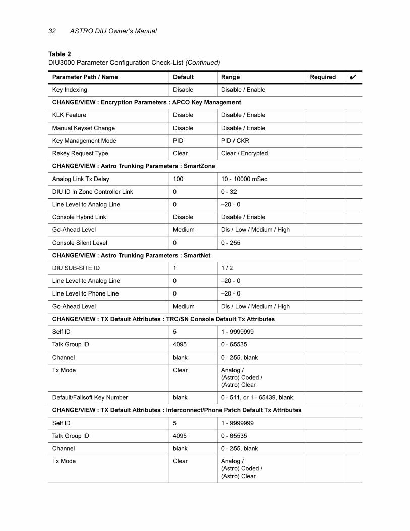
32 ASTRO DIU Owner’s Manual
Key Indexing Disable Disable / Enable
CHANGE/VIEW : Encryption Parameters : APCO Key Management
KLK Feature Disable Disable / Enable
Manual Keyset Change Disable Disable / Enable
Key Management Mode PID PID / CKR
Rekey Request Type Clear Clear / Encrypted
CHANGE/VIEW : Astro Trunking Parameters : SmartZone
Analog Link Tx Delay 100 10 - 10000 mSec
DIU ID In Zone Controller Link 0 0 - 32
Line Level to Analog Line 0 –20 - 0
Console Hybrid Link Disable Disable / Enable
Go-Ahead Level Medium Dis / Low / Medium / High
Console Silent Level 0 0 - 255
CHANGE/VIEW : Astro Trunking Parameters : SmartNet
DIU SUB-SITE ID 1 1 / 2
Line Level to Analog Line 0 –20 - 0
Line Level to Phone Line 0 –20 - 0
Go-Ahead Level Medium Dis / Low / Medium / High
CHANGE/VIEW : TX Default Attributes : TRC/SN Console Default Tx Attributes
Self ID 5 1 - 9999999
Talk Group ID 4095 0 - 65535
Channel blank 0 - 255, blank
Tx Mode Clear Analog /
(Astro) Coded /
(Astro) Clear
Default/Failsoft Key Number blank 0 - 511, or 1 - 65439, blank
CHANGE/VIEW : TX Default Attributes : Interconnect/Phone Patch Default Tx Attributes
Self ID 5 1 - 9999999
Talk Group ID 4095 0 - 65535
Channel blank 0 - 255, blank
Tx Mode Clear Analog /
(Astro) Coded /
(Astro) Clear
Table 2
DIU3000 Parameter Configuration Check-List (Continued)
Parameter Path / Name Default Range Required �

Installation Instructions 33
Key Number blank 0 -511, or 1 - 65439, blank
Slaving Mode STRAP STRAP / SLAVE / STEER
DTMF Output Connected to: Console W/Li Yes Yes / No
DTMF Output Connected to: E&M
Console
Yes Yes / No
DTMF Output Connected to: MRTI Patch Yes Yes / No
DTMF Output Connected to: Speaker Yes Yes / No
Standard DTMF Digit Tone Duration 100 50 - 3000 mSec
Long DTMF Digit Tone Duration 100 50 - 3000 mSec
Pause Duration 1000 500 - 4000 mSec
Auto Dial HoldOff Count 0 0 - 20
CHANGE/VIEW : TX Default Attributes : Handset Default TX Attributes
Self ID 5 1 - 9999999
Talk Group ID 4095 0 - 65535
Channel blank 0 - 255, blank
Tx Mode Clear Analog /
(Astro) Coded /
(Astro) Clear
Key Number blank 0 - 511, or 1 - 65439, blank
CHANGE/VIEW : TX Default Attributes : E&M Console Default Attributes
Self ID 5 1 - 9999999
Talk Group ID 4095 0 - 65535
Channel blank 0 - 255, blank
Tx Mode Clear Analog /
(Astro) Clear /
(Astro) Coded
Key Number blank 0 - 511, or 1 - 65439, blank
Table 2
DIU3000 Parameter Configuration Check-List (Continued)
Parameter Path / Name Default Range Required �
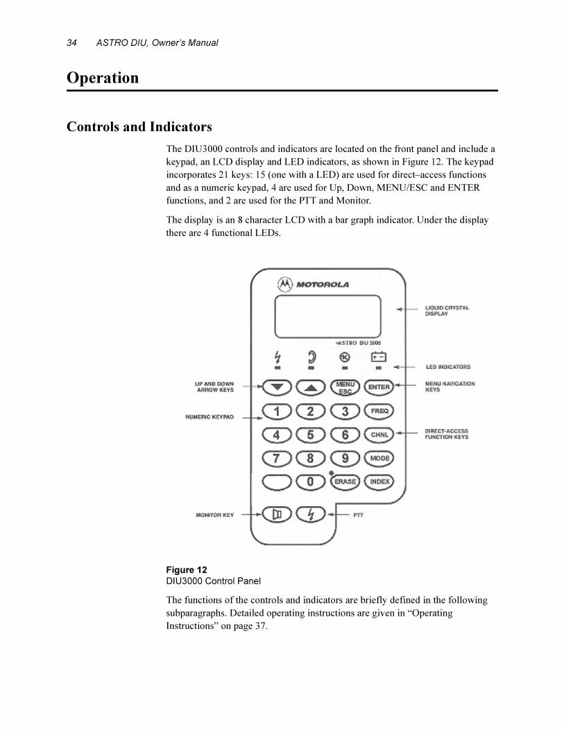
34 ASTRO DIU, Owner’s Manual
Operation
Controls and Indicators
The DIU3000 controls and indicators are located on the front panel and include a
keypad, an LCD display and LED indicators, as shown in Figure 12. The keypad
incorporates 21 keys: 15 (one with a LED) are used for direct–access functions
and as a numeric keypad, 4 are used for Up, Down, MENU/ESC and ENTER
functions, and 2 are used for the PTT and Monitor.
The display is an 8 character LCD with a bar graph indicator. Under the display
there are 4 functional LEDs.
.
The functions of the controls and indicators are briefly defined in the following
subparagraphs. Detailed operating instructions are given in “Operating
Instructions” on page 37.
Figure 12
DIU3000 Control Panel
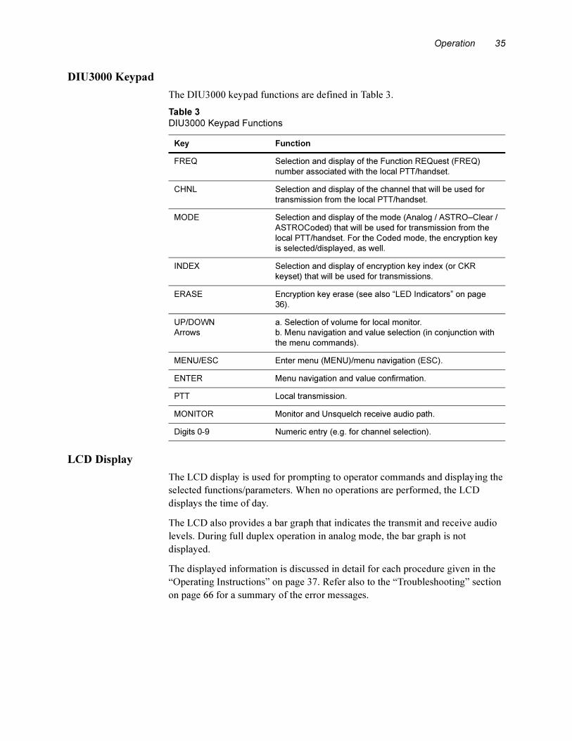
Operation 35
DIU3000 Keypad
The DIU3000 keypad functions are defined in Table 3.
LCD Display
The LCD display is used for prompting to operator commands and displaying the
selected functions/parameters. When no operations are performed, the LCD
displays the time of day.
The LCD also provides a bar graph that indicates the transmit and receive audio
levels. During full duplex operation in analog mode, the bar graph is not
displayed.
The displayed information is discussed in detail for each procedure given in the
“Operating Instructions” on page 37. Refer also to the “Troubleshooting” section
on page 66 for a summary of the error messages.
Table 3
DIU3000 Keypad Functions
Key Function
FREQ Selection and display of the Function REQuest (FREQ)
number associated with the local PTT/handset.
CHNL Selection and display of the channel that will be used for
transmission from the local PTT/handset.
MODE Selection and display of the mode (Analog / ASTRO–Clear /
ASTROCoded) that will be used for transmission from the
local PTT/handset. For the Coded mode, the encryption key
is selected/displayed, as well.
INDEX Selection and display of encryption key index (or CKR
keyset) that will be used for transmissions.
ERASE Encryption key erase (see also “LED Indicators” on page
36).
UP/DOWN
Arrows
a. Selection of volume for local monitor.
b. Menu navigation and value selection (in conjunction with
the menu commands).
MENU/ESC Enter menu (MENU)/menu navigation (ESC).
ENTER Menu navigation and value confirmation.
PTT Local transmission.
MONITOR Monitor and Unsquelch receive audio path.
Digits 0-9 Numeric entry (e.g. for channel selection).
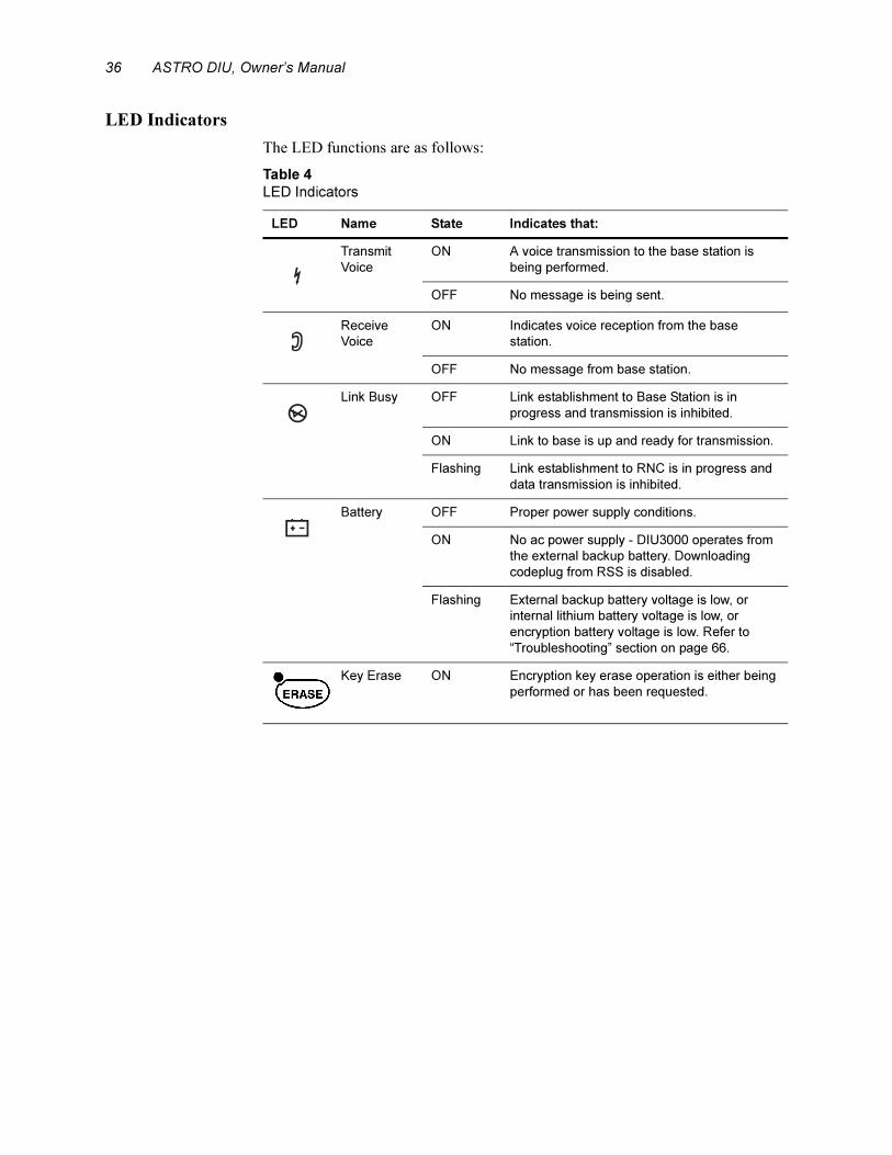
36 ASTRO DIU, Owner’s Manual
LED Indicators
The LED functions are as follows:
Table 4
LED Indicators
LED Name State Indicates that:
Transmit
Voice
ON A voice transmission to the base station is
being performed.
OFF No message is being sent.
Receive
Voice
ON Indicates voice reception from the base
station.
OFF No message from base station.
Link Busy OFF Link establishment to Base Station is in
progress and transmission is inhibited.
ON Link to base is up and ready for transmission.
Flashing Link establishment to RNC is in progress and
data transmission is inhibited.
Battery OFF Proper power supply conditions.
ON No ac power supply - DIU3000 operates from
the external backup battery. Downloading
codeplug from RSS is disabled.
Flashing External backup battery voltage is low, or
internal lithium battery voltage is low, or
encryption battery voltage is low. Refer to
“Troubleshooting” section on page 66.
Key Erase ON Encryption key erase operation is either being
performed or has been requested.
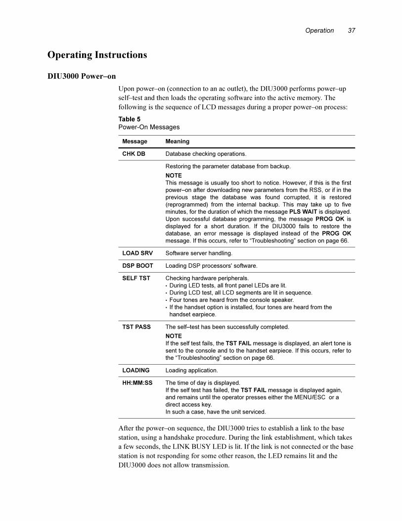
Operation 37
Operating Instructions
DIU3000 Power–on
Upon power–on (connection to an ac outlet), the DIU3000 performs power–up
self–test and then loads the operating software into the active memory. The
following is the sequence of LCD messages during a proper power–on process:
After the power–on sequence, the DIU3000 tries to establish a link to the base
station, using a handshake procedure. During the link establishment, which takes
a few seconds, the LINK BUSY LED is lit. If the link is not connected or the base
station is not responding for some other reason, the LED remains lit and the
DIU3000 does not allow transmission.
Table 5
Power-On Messages
Message Meaning
CHK DB Database checking operations.
Restoring the parameter database from backup.
NOTE
This message is usually too short to notice. However, if this is the first
power–on after downloading new parameters from the RSS, or if in the
previous stage the database was found corrupted, it is restored
(reprogrammed) from the internal backup. This may take up to five
minutes, for the duration of which the message PLS WAIT is displayed.
Upon successful database programming, the message PROG OK is
displayed for a short duration. If the DIU3000 fails to restore the
database, an error message is displayed instead of the PROG OK
message. If this occurs, refer to “Troubleshooting” section on page 66.
LOAD SRV Software server handling.
DSP BOOT Loading DSP processors' software.
SELF TST Checking hardware peripherals.
• During LED tests, all front panel LEDs are lit.
• During LCD test, all LCD segments are lit in sequence.
• Four tones are heard from the console speaker.
• If the handset option is installed, four tones are heard from the
handset earpiece.
TST PASS The self–test has been successfully completed.
NOTE
If the self test fails, the TST FAIL message is displayed, an alert tone is
sent to the console and to the handset earpiece. If this occurs, refer to
the “Troubleshooting” section on page 66.
LOADING Loading application.
HH:MM:SS The time of day is displayed.
If the self test has failed, the TST FAIL message is displayed again,
and remains until the operator presses either the MENU/ESC or a
direct access key.
In such a case, have the unit serviced.
38 ASTRO DIU, Owner’s Manual
In the ready state, the LCD displays the time of day and the unit is ready for
operation. Any control equipment connected to the DIU3000 can now be used for
controlling the base station.
Menu Command Reference
Most of DIU3000 operating parameters can be controlled using the DIU RSS.
However, some of the parameters should be set or changed more frequently,
without the need to connect an external computer. These parameters are accessed
via the MENU/ESC key.
Menu Navigation
Accessing the Menu Commands
The parameters and functions accessed via the MENU/ESC key are organized in
a tree-like structure, or a “menu", shown in Figure 13.
Moving between same level menu entries is performed using the [^]/[|] arrows;
moving to an inner level menu entry is performed using the ENTR key.
The states at which parameter value can actually be set and functions activated are
located at an additional level, not shown in Figure 13. The figure shows only the
paths to those states. The states are accessed by pressing the ENTR key from the
last level shown.
Changing a Value
In this state the LCD display usually blinks. There are two possible methods to
change a value:
• Scrolling through the available options using the [^]/[|] arrow keys.
• Keying in a numeric value using the 10–digit numeric keypad.
In some of the cases only one of the methods is available, as detailed in the
procedures in the following paragraphs. Both methods require the usage of the
ENTR key for selection confirmation and movement to the upper tree level.
If arrow keys are used for displaying the available values, then the process is
circular.
If the numeric keypad is used for changing a value, and the value is out of range,
an error message is displayed for a short period, and the previously active value is
displayed again.
Cancelling the Menu Commands
Pressing MENU/ESC while performing a Menu command will return to the
previous level menu entry without performing the selected function. If the first
level has already been reached, pressing MENU/ESC will exit the menu
command mode and return to the ready state (time of day display).
Error Messages
The “Troubleshooting” section on page 66 describes the error messages that are
displayed in case of incorrect operation.

Operation 39
.
Figure 13
Menu Operation Tree
READY STATE
(TIME OF DAY DISPLAY)
ACTIVITYINBOUND CONSOLEE AND M MRTI USER
CLOCKSET
BASE DBM AGC
AUTO
SLNT
MRTI
ID DBM AUTO
SLNT
CONSOLE
E AND M
EDITPSWD
ERR LIST
HANDSET
LCD
LOGIN
LOGOUT
SERVICE
TESTS
TX PARAMS
MAINT USER CRYPTO
ID DBM
ID DBM
AGC
AUTO
SLNT
ID MICSNS
TIME FMT LIGHT CONTRS
MAINT USER CRYPTO
LOGIN LOGOUT
MAINT USER CRYPTO
AUD LOOP
ACCS
AGC
LEGEND
*NOTE: The TESTS menu is visible only after entering the Service password.
OTAR RKEY REQ
Use arrows [^]/[|]
Use [ENTR] key

40 ASTRO DIU, Owner’s Manual
ACTIVITY
This menu provides a means of monitoring transmit/receive parameters of the
DIU3000 and control devices connected to it.
• For the CONSOLE (TRC type analog console), the CHaNneL and MODE
parameters of the current transmission can be traced. If not currently
transmitting, the last active parameters are displayed.
• For the USER (local user, handset), the Function REQuest no., CHaNneL and
MODE parameters of the current transmission can be traced. If not currently
transmitting, the last active parameters are displayed.
• For the INBOUND activity, the MODE parameter can be traced. If there is
currently no inbound activity, the MODE of the last inbound reception is
displayed.
Table 6
Action LCD Display Comments
1. While in the ready mode, press MENU/
ESC to enter the menu mode.
The last accessed menu entry is shown.
2. Scroll until ACTIVITY is shown. ACTIVITY
3. Press ENTR to enter the device selection
menu.
CONSOLE
or
USER
or
INBOUND
4. Scroll to display the required device
option.
5. Press ENTR to display activity
parameters that can be traced for the
selected device.
FREQ nnn
or
CHNL nnn
or
ANALOG/
CLEAR/
ENCR nnn
• The data displayed is updated once a
second, or if ENTR is pressed.
• If there was no inbound process since
power–up and ENTR is pressed while in
INBOUND ACTIVITY display state, the
message NO INFO is displayed.
NOTE
• For the CONSOLE activity, only the CHaNnel and MODE parameters can be traced.
• For the INBOUND activity, only the MODE parameter can be traced.
6. Use the arrow keys to scroll between the
available parameters.
7. Press MENU/ESC to return to the device
selection menu.
CONSOLE
or
USER
or
INBOUND
8. Repeat steps 4 to 7 to trace another device, or press MENU/ESC twice to
return to the ready state.
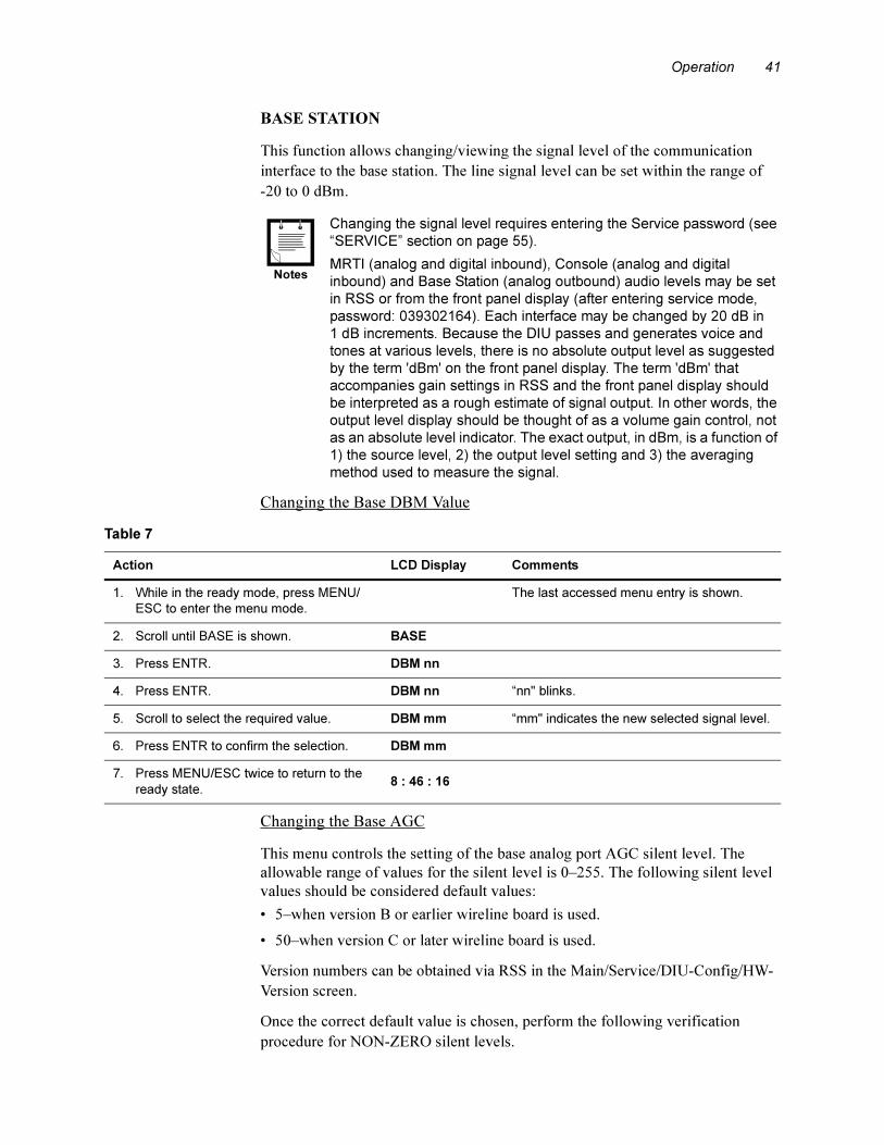
Operation 41
BASE STATION
This function allows changing/viewing the signal level of the communication
interface to the base station. The line signal level can be set within the range of
-20 to 0 dBm.
.
Changing the Base DBM Value
Changing the Base AGC
This menu controls the setting of the base analog port AGC silent level. The
allowable range of values for the silent level is 0–255. The following silent level
values should be considered default values:
• 5–when version B or earlier wireline board is used.
• 50–when version C or later wireline board is used.
Version numbers can be obtained via RSS in the Main/Service/DIU-Config/HW-
Version screen.
Once the correct default value is chosen, perform the following verification
procedure for NON-ZERO silent levels.
Changing the signal level requires entering the Service password (see
“SERVICE” section on page 55).
MRTI (analog and digital inbound), Console (analog and digital
inbound) and Base Station (analog outbound) audio levels may be set
in RSS or from the front panel display (after entering service mode,
password: 039302164). Each interface may be changed by 20 dB in
1 dB increments. Because the DIU passes and generates voice and
tones at various levels, there is no absolute output level as suggested
by the term 'dBm' on the front panel display. The term 'dBm' that
accompanies gain settings in RSS and the front panel display should
be interpreted as a rough estimate of signal output. In other words, the
output level display should be thought of as a volume gain control, not
as an absolute level indicator. The exact output, in dBm, is a function of
1) the source level, 2) the output level setting and 3) the averaging
method used to measure the signal.
Notes
Table 7
Action LCD Display Comments
1. While in the ready mode, press MENU/
ESC to enter the menu mode.
The last accessed menu entry is shown.
2. Scroll until BASE is shown. BASE
3. Press ENTR. DBM nn
4. Press ENTR. DBM nn “nn" blinks.
5. Scroll to select the required value. DBM mm “mm" indicates the new selected signal level.
6. Press ENTR to confirm the selection. DBM mm
7. Press MENU/ESC twice to return to the
ready state.8 : 46 : 16

42 ASTRO DIU, Owner’s Manual
Silent Level Verification Test:
This procedure should be used to verify that NON-ZERO silent levels are set
properly.
1. Enter the DIU’s Maintenance Password (039302164) at the DIU’s front panel.
2. Go to the DIU’s front panel menu labeled Base -> AGC -> AUTO.
3. Press [Enter] on the DIU’s front panel. The screen should now flash “AUTO
RDY”.
4. Start an inbound analog call. If using a subscriber, use strong signal
conditions.
5. While background noise is being transmitted (i.e. no audio), press [Enter] on the
DIU’s front panel.
6. Take note of this number returned on the DIU’s display.
7. While the inbound call is still active, place a –10 dBm tone on the base -> DIU
wireline.
8. Press [Enter] on the DIU’s front panel. The screen should now flash “AUTO
RDY”.
9. While the tone is connected press [Enter] on the DIU’s front panel.
10. Take note of the number returned on the DIU’s display.
11. Verify or change the silent level using the “Results” section below and
program the DIU with this value.
Results:
– If the default silent level is equal to or greater than the number returned in
step 6, use the default silent level. This number should be less than the number
returned in step 10.
– If the default silent level is less than the number returned in step 6 and the DIU
has version B or earlier Wireline board, use the number returned in step 6 as the
silent level.
– If the default silent level is less than the number returned in step 6 and the DIU
has version C or later Wireline board, use the number returned in step 6 and add
20 to it.
.
The silent level chosen should be in between the two numbers
returned in steps 6 and 10. If the DIU input is noisy then the two
numbers may be very close. This situation will lead to poor operation.
The DIU will not be able to accurately differentiate between audio and
noise. In this case it is best to select the value returned in step 6 to
ensure audio will trip the silent level.
Note
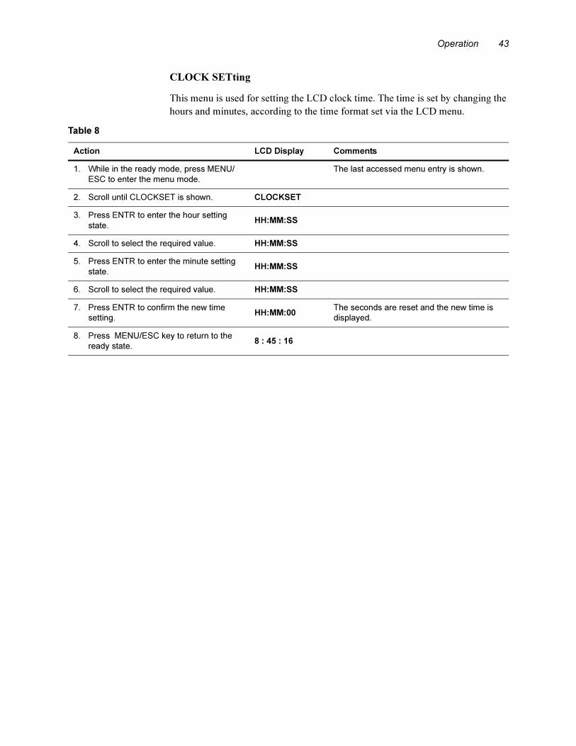
Operation 43
CLOCK SETting
This menu is used for setting the LCD clock time. The time is set by changing the
hours and minutes, according to the time format set via the LCD menu.
Table 8
Action LCD Display Comments
1. While in the ready mode, press MENU/
ESC to enter the menu mode.
The last accessed menu entry is shown.
2. Scroll until CLOCKSET is shown. CLOCKSET
3. Press ENTR to enter the hour setting
state.HH:MM:SS
4. Scroll to select the required value. HH:MM:SS
5. Press ENTR to enter the minute setting
state.HH:MM:SS
6. Scroll to select the required value. HH:MM:SS
7. Press ENTR to confirm the new time
setting.HH:MM:00
The seconds are reset and the new time is
displayed.
8. Press MENU/ESC key to return to the
ready state.8 : 45 : 16

44 ASTRO DIU, Owner’s Manual
CONSOLE
This menu controls the parameters of the communication interface to the analog
console. In the current version of the DIU3000, only the TRC type analog console
is supported. The following parameter can be changed:
– Line signal level. The line signal level can be set within the range of –20 to
0 dBm.
.
The following parameter can be viewed:
– ID. Enables viewing the console ID, shown in hexadecimal format.
Changing the line signal level requires entering the Service password
(see “SERVICE” section on page 55).
MRTI (analog and digital inbound), Console (analog and digital
inbound) and Base Station (analog outbound) audio levels may be set
in RSS or from the front panel display (after entering service mode,
password: 039302164). Each interface may be changed by 20 dB in
1 dB increments. Because the DIU passes and generates voice and
tones at various levels, there is no absolute output level as suggested
by the term 'dBm' on the front panel display. The term 'dBm' that
accompanies gain settings in RSS and the front panel display should
be interpreted as a rough estimate of signal output. In other words, the
output level display should be thought of as a volume gain control, not
as an absolute level indicator. The exact output, in dBm, is a function of
1) the source level, 2) the output level setting and 3) the averaging
method used to measure the signal.
Notes
Table 9
Action LCD Display Comments
1. While in the ready mode, press MENU/
ESC to enter the menu mode.
The last accessed menu entry is shown.
2. Scroll until CONSOLE is shown. CONSOLE
3. Press ENTR to display the options. DBM nn
or
ID HHH
4. Scroll to select the required option. ID HHH shows the console ID in hexadecimal
format.
If changing/viewing of line signal level is not required, skip to step 9.
5. Scroll to select the DBM option.DBM nn
“nn" indicates the currently selected signal
level in dBm units.
6. Press ENTR. DBM nn “nn" blinks.
7. Scroll to select the required value. DBM mm “mm" indicates the new selected signal level.
8. Press ENTR to confirm the selection. DBM mm
9. Press MENU/ESC twice to return to the
ready state.8 : 46 : 16
Operation 45
Console AGC
This menu controls the setting of the console analog port AGC silent level. The
allowable range of values for the silent level is 0-255. The following silent level
values should be considered default values.
• 0–only TRC consoles with version B or earlier wireline board.
• 5–only digital keying consoles (DKC) with version B or earlier wireline board.
• 0–both TRC and DKC consoles with version B or earlier wireline board.
• 50–if TRC, DKC, or both (TRC and DKC) consoles with version C or later
wireline board.
Wireline version numbers can be obtained via RSS in the Main/Service/DIU-
Config/HW-Version screen.
Once the correct default value is chosen, perform the following verification
procedure for NON-ZERO silent levels.
Silent Level Verification Test:
This procedure should be used to verify that NON-ZERO silent levels are set
properly.
1. Enter the DIU's Maintenance Password (039302164) at the DIU's front panel.
2. Go to the DIU's front panel menu labeled CONSOLE -> AGC -> AUTO.
3. Press [Enter] on the DIU's front panel. The screen should now flash “AUTO
RDY”.
4. Start an outbound call from the console.
5. While background noise is being transmitted (i.e. no audio), press [Enter] on the
DIU's front panel.
6. Take note of the number returned on the DIU's display.
7. While the console is still keyed, place a -10 dBm tone on the console ->DIU
wireline.
8. Press [Enter] on the DIU's front panel. The screen should now flash “AUTO
RDY”.
9. While the tone is being transmitted press [Enter] on the DIU's front panel.
10. Take note of the number returned on the DIU's display.
11. Verify or change the silent level using the “Results” section below and
program the DIU with this value.
Results:
– If the default silent level is equal to or greater than the number returned in
step 6, use the default silent level. This number should be less than the
number returned in step 10.
– If the default silent level is less than the number returned in Step 6 and the
DIU has version B or earlier Wireline Board, use the number returned in step
6 as the silent level.

46 ASTRO DIU, Owner’s Manual
– If the default silent level is less than the number returned in step 6 and the
DIU has version C or later Wireline Board, use the number returned in step 6
and add 20 to it.
.
The silent level chosen should be in between the two numbers
returned in steps 6 and 10. If the DIU input is noisy then the two
numbers may be very close. This situation will lead to poor operation.
The DIU will not be able to accurately differentiate between audio and
noise. In this case it is best to select the value returned in step 6 to
ensure audio will trip the silent level.
Note
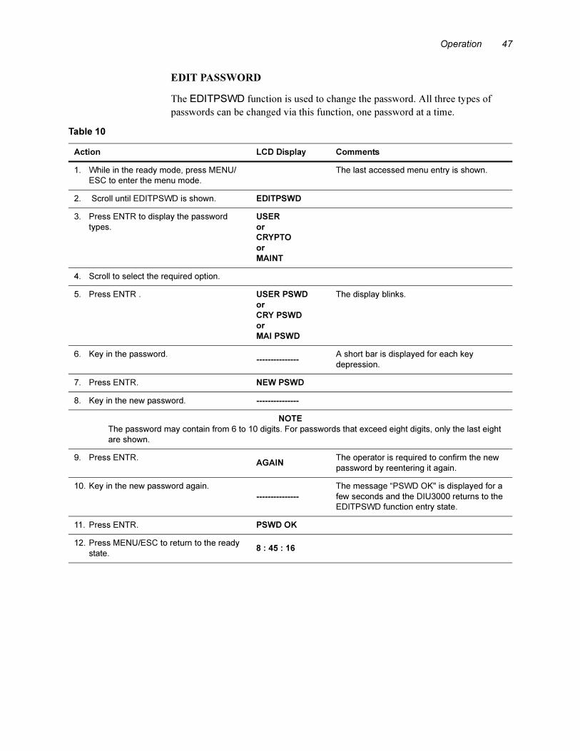
Operation 47
EDIT PASSWORD
The EDITPSWD function is used to change the password. All three types of
passwords can be changed via this function, one password at a time.
Table 10
Action LCD Display Comments
1. While in the ready mode, press MENU/
ESC to enter the menu mode.
The last accessed menu entry is shown.
2. Scroll until EDITPSWD is shown. EDITPSWD
3. Press ENTR to display the password
types.
USER
or
CRYPTO
or
MAINT
4. Scroll to select the required option.
5. Press ENTR . USER PSWD
or
CRY PSWD
or
MAI PSWD
The display blinks.
6. Key in the password.---------------
A short bar is displayed for each key
depression.
7. Press ENTR. NEW PSWD
8. Key in the new password. ---------------
NOTE
The password may contain from 6 to 10 digits. For passwords that exceed eight digits, only the last eight
are shown.
9. Press ENTR.AGAIN
The operator is required to confirm the new
password by reentering it again.
10. Key in the new password again.
---------------
The message “PSWD OK" is displayed for a
few seconds and the DIU3000 returns to the
EDITPSWD function entry state.
11. Press ENTR. PSWD OK
12. Press MENU/ESC to return to the ready
state.8 : 45 : 16
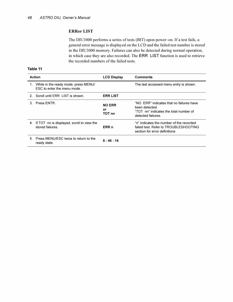
48 ASTRO DIU, Owner’s Manual
ERRor LIST
The DIU3000 performs a series of tests (BIT) upon power–on. If a test fails, a
general error message is displayed on the LCD and the failed test number is stored
in the DIU3000 memory. Failures can also be detected during normal operation,
in which case they are also recorded. The ERR LIST function is used to retrieve
the recorded numbers of the failed tests.
Table 11
Action LCD Display Comments
1. While in the ready mode, press MENU/
ESC to enter the menu mode.
The last accessed menu entry is shown.
2. Scroll until ERR LIST is shown. ERR LIST
3. Press ENTR.NO ERR
or
TOT nn
“NO ERR" indicates that no failures have
been detected.
“TOT nn" indicates the total number of
detected failures.
4. If TOT nn is displayed, scroll to view the
stored failures. ERR n
“n" indicates the number of the recorded
failed test. Refer to TROUBLESHOOTING
section for error definitions
5. Press MENU/ESC twice to return to the
ready state.8 : 46 : 16

Operation 49
HANDSET
This menu is used for controlling the local handset microphone sensitivity and for
viewing the handset ID. The microphone sensitivity allowed range is 0 - 9. The
handset ID can be viewed but not changed. It can be set only by the RSS. The
handset ID is shown in hexadecimal format.
.
Changing the microphone sensitivity level requires entering the
Service password (see “SERVICE” section on page 55).
Note
Table 12
Action LCD Display Comments
1. While in the ready mode, press MENU/
ESC to enter the menu mode.
The last accessed menu entry is shown.
2. Scroll until HANDSET is shown. HANDSET
3. Press ENTR.ID HHH
or
MICSNS n
“ID HHH" indicates the current ID in
hexadecimal format;
“MICSNS n" indicates the current
microphone sensitivity.
4. Scroll to select the required option. ID HHH
or
MICSNS n
5. Press ENTR. MICSNS n “n" blinks.
6. Scroll between the available options or
key in the required value (0 - 9).MICSNS m
“m" blinks.
7. Press ENTR to confirm the selection. MICSNS m
8. Press MENU/ESC twice to return to the
ready state.8 : 46 : 16

50 ASTRO DIU, Owner’s Manual
LCD
This menu controls the current setting of the LCD. The following display
properties may be changed:
– Brightness. Three brightness levels are available: LIGHT 0 through
LIGHT 2.
– Contrast. Ten levels are available: CONTRS 0 through CONTRS 9.
– Time format. The user can select either a 12 and 24 hour format.
Changing the LCD Contrast Level
Table 13
Action LCD Display Comments
1. While in the ready mode, press MENU/
ESC to enter the menu mode.
The last accessed menu entry is shown.
2. Scroll until LCD is shown. LCD
3. Press ENTR to display the options. CONTRS n
or
LIGHT n
or
TIME FMT
“n" indicates the currently selected level.
4. Scroll to select the required option. CONTRS n
or
LIGHT n
or
TIME FMT
For the following instructions refer to
• “Changing the LCD Contrast Level” section on page 51 for changing the contrast; or
• “Changing the LCD Brightness (Light) Level” section on page 52 for changing the brightness; or
• “Changing the Time Format” section on page 52 for changing the time format.
Table 14
Action LCD Display Comments
1. Perform the instructions given in “LCD”
section on page 51.CONTRS n
“n"indicates the currently selected level.
2. Press ENTR CONTRS n “n" blinks.
3. Scroll to select (or key in) the required
value.
CONTRS m
The display contrast is updated immediately
upon each change. The number indicating
the contrast level continues blinking to
indicate that the DIU3000 is still in the
contrast changing mode
4. Press ENTR or MENU/ESC to exit the
contrast changing state.CONTRS m
The MENU/ESC key can also be used in this
step to exit the property changing state, since
the display contrast is updated immediately
and no selection confirmation is required.
5. Press MENU/ESC twice to return to the
ready state.8 : 46 : 16
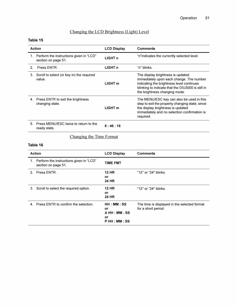
Operation 51
Changing the LCD Brightness (Light) Level
Changing the Time Format
Table 15
Action LCD Display Comments
1. Perform the instructions given in “LCD”
section on page 51.LIGHT n
“n"indicates the currently selected level.
2. Press ENTR. LIGHT n “n" blinks.
3. Scroll to select (or key in) the required
value.
LIGHT m
The display brightness is updated
immediately upon each change. The number
indicating the brightness level continues
blinking to indicate that the DIU3000 is still in
the brightness changing mode.
4. Press ENTR to exit the brightness
changing state.
LIGHT m
The MENU/ESC key can also be used in this
step to exit the property changing state, since
the display brightness is updated
immediately and no selection confirmation is
required.
5. Press MENU/ESC twice to return to the
ready state.8 : 46 : 16
Table 16
Action LCD Display Comments
1. Perform the instructions given in “LCD”
section on page 51.TIME FMT
2. Press ENTR. 12 HR
or
24 HR
“12" or “24" blinks.
3. Scroll to select the required option. 12 HR
or
24 HR
“12" or “24" blinks.
4. Press ENTR to confirm the selection. HH : MM : SS
or
A HH : MM : SS
or
P HH : MM : SS
The time is displayed in the selected format
for a short period.
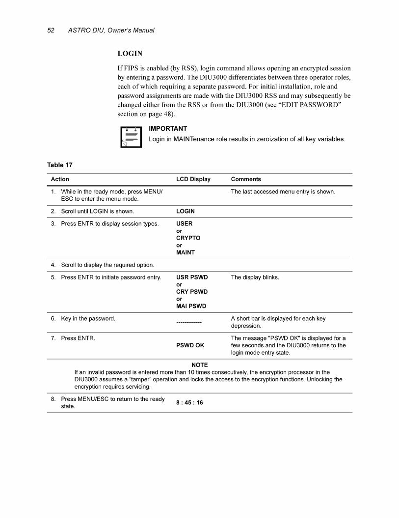
52 ASTRO DIU, Owner’s Manual
LOGIN
If FIPS is enabled (by RSS), login command allows opening an encrypted session
by entering a password. The DIU3000 differentiates between three operator roles,
each of which requiring a separate password. For initial installation, role and
password assignments are made with the DIU3000 RSS and may subsequently be
changed either from the RSS or from the DIU3000 (see “EDIT PASSWORD”
section on page 48).
.
IMPORTANT
Login in MAINTenance role results in zeroization of all key variables.
Table 17
Action LCD Display Comments
1. While in the ready mode, press MENU/
ESC to enter the menu mode.
The last accessed menu entry is shown.
2. Scroll until LOGIN is shown. LOGIN
3. Press ENTR to display session types. USER
or
CRYPTO
or
MAINT
4. Scroll to display the required option.
5. Press ENTR to initiate password entry. USR PSWD
or
CRY PSWD
or
MAI PSWD
The display blinks.
6. Key in the password.-------------
A short bar is displayed for each key
depression.
7. Press ENTR.
PSWD OK
The message "PSWD OK" is displayed for a
few seconds and the DIU3000 returns to the
login mode entry state.
NOTE
If an invalid password is entered more than 10 times consecutively, the encryption processor in the
DIU3000 assumes a “tamper” operation and locks the access to the encryption functions. Unlocking the
encryption requires servicing.
8. Press MENU/ESC to return to the ready
state.8 : 45 : 16
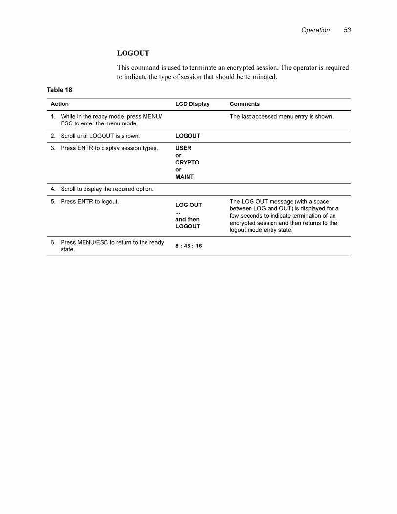
Operation 53
LOGOUT
This command is used to terminate an encrypted session. The operator is required
to indicate the type of session that should be terminated.
Table 18
Action LCD Display Comments
1. While in the ready mode, press MENU/
ESC to enter the menu mode.
The last accessed menu entry is shown.
2. Scroll until LOGOUT is shown. LOGOUT
3. Press ENTR to display session types. USER
or
CRYPTO
or
MAINT
4. Scroll to display the required option.
5. Press ENTR to logout.LOG OUT
...
and then
LOGOUT
The LOG OUT message (with a space
between LOG and OUT) is displayed for a
few seconds to indicate termination of an
encrypted session and then returns to the
logout mode entry state.
6. Press MENU/ESC to return to the ready
state.8 : 45 : 16

54 ASTRO DIU, Owner’s Manual
SERVICE
The SERVICE menu is used to log into and out of the service session. Logging
into the service session is a prerequisite for changing the following DIU3000
parameters:
– The signal level of the communication interface to the base station (see
“BASE STATION” section on page 41).
– The signal level of the communication interface to the console (see
“CONSOLE” section on page 44).
– The local handset microphone sensitivity level (see “HANDSET” section on
page 50).
The service password is constant and preset to “039302164".
The Service session can be active concurrently with any of the encrypted sessions.
Initiating a Service Session
Table 19
Action LCD Display Comments
1. While in the ready mode, press MENU/
ESC to enter the menu mode.
The last accessed menu entry is shown.
2. Scroll until SERVICE is shown. SERVICE
3. Press ENTR to display options. LOGIN
or
LOGOUT
4. Scroll to display LOGIN. LOGIN
5. Press ENTR to initiate password entry. SRV PSWD The display blinks.
6. Key in the password - “039302164".----------------
A short bar is displayed for each key
depression.
7. Press ENTR.
PSWD OK
The message "PSWD OK" is displayed for a
few seconds and the DIU3000 returns to the
SERVICE display.
8. Press MENU/ESC to return to the ready
state.8 : 45 : 16
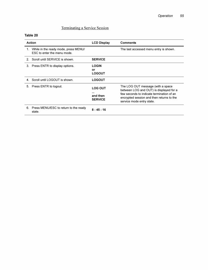
Operation 55
Terminating a Service Session
Table 20
Action LCD Display Comments
1. While in the ready mode, press MENU/
ESC to enter the menu mode.
The last accessed menu entry is shown.
2. Scroll until SERVICE is shown. SERVICE
3. Press ENTR to display options. LOGIN
or
LOGOUT
4. Scroll until LOGOUT is shown. LOGOUT
5. Press ENTR to logout.LOG OUT
...
and then
SERVICE
The LOG OUT message (with a space
between LOG and OUT) is displayed for a
few seconds to indicate termination of an
encrypted session and then returns to the
service mode entry state.
6. Press MENU/ESC to return to the ready
state.8 : 45 : 16
56 ASTRO DIU, Owner’s Manual
TESTS
This menu currently includes the Audio Loop test. In the future DIU3000
versions, the menu will provide access to additional tests.
.
Audio Loop Test
This test is used for stand alone testing of the DIU3000 during system
troubleshooting. For details, refer to Figure 14 on page 77.
Performing the Audio Loop test requires entering the Service
password.
Note

Operation 57
TX PARAMS
The TX PARMS (Transmission Parameters) menu is used only for changing the
access code for local transmission. This access code is attached to the outgoing
messages sent from the DIU3000 using the PTT or local handset.
The access code allowable range is 0 to 255 and “none". When “none" is selected
(“- - -" is displayed), no access code is included in the transmission. The value
“none" is selected by scrolling to “- - -" or keying in a value larger than 255.
Table 21
Action LCD Display Comments
1. While in the ready mode, press MENU/
ESC to enter the menu mode.
The last accessed menu entry is shown.
2. Scroll until TX PARMS is shown. TX PARMS
3. Press ENTR to display the parameter
options (currently only the Access Code).ACCS nnn
“nnn" indicates the current access code
value.
4. Press ENTR to enter the access code
editing state.ACCS nnn
“nnn" blinks.
NOTE
Pressing MENU/ESC at this stage will return to the access code display state retaining the previous value.
5. Scroll between the available values or
key in the required value. ACCS mmm
“mmm" blinks. Selecting the “- - -" value by
scrolling or keying in a value larger than 255
sets the access code to “none".
6. Press ENTR to confirm the selection.ACCS mmm
The DIU3000 returns to the access code
display state.
7. Press MENU/ESC key twice to return to
the ready state.8 : 45 : 16
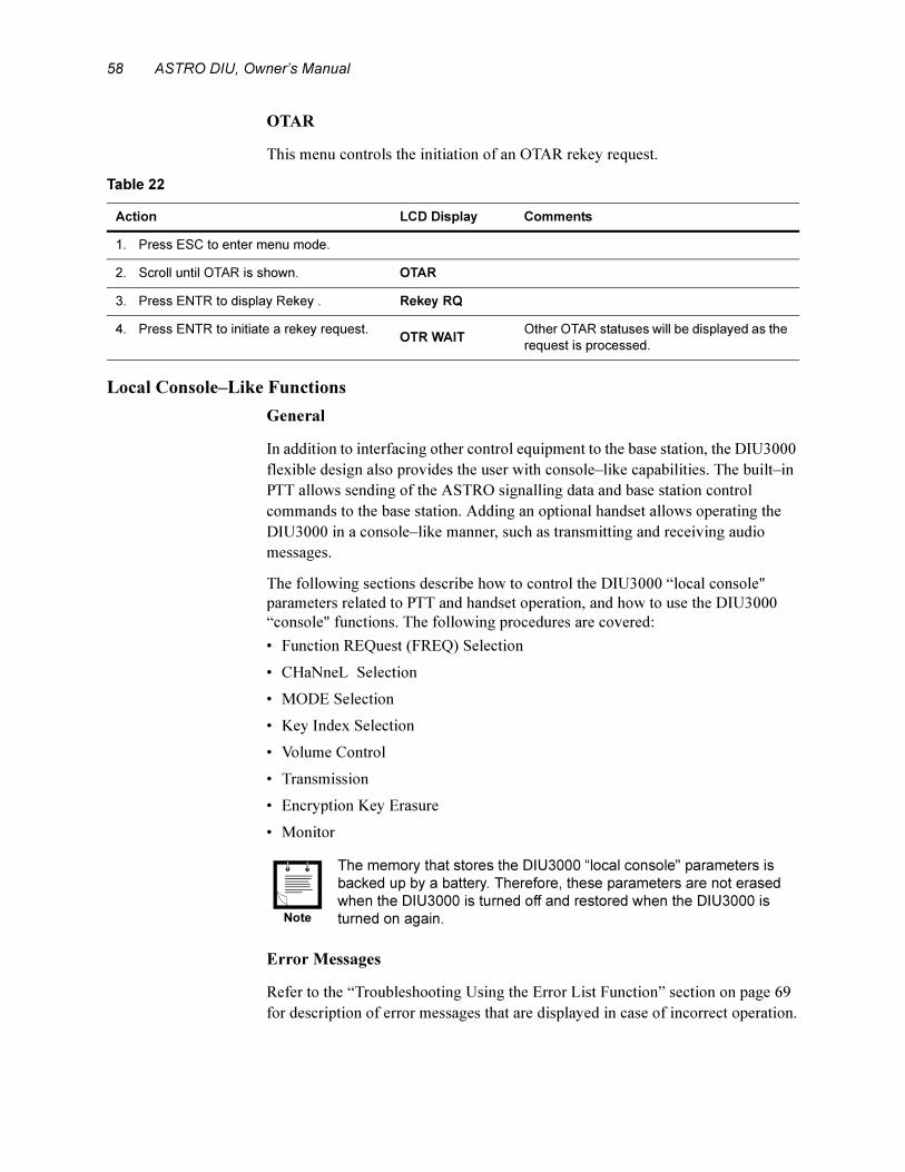
58 ASTRO DIU, Owner’s Manual
OTAR
This menu controls the initiation of an OTAR rekey request.
Local Console–Like Functions
General
In addition to interfacing other control equipment to the base station, the DIU3000
flexible design also provides the user with console–like capabilities. The built–in
PTT allows sending of the ASTRO signalling data and base station control
commands to the base station. Adding an optional handset allows operating the
DIU3000 in a console–like manner, such as transmitting and receiving audio
messages.
The following sections describe how to control the DIU3000 “local console"
parameters related to PTT and handset operation, and how to use the DIU3000
“console" functions. The following procedures are covered:
• Function REQuest (FREQ) Selection
• CHaNneL Selection
• MODE Selection
• Key Index Selection
• Volume Control
• Transmission
• Encryption Key Erasure
• Monitor
.
Error Messages
Refer to the “Troubleshooting Using the Error List Function” section on page 69
for description of error messages that are displayed in case of incorrect operation.
Table 22
Action LCD Display Comments
1. Press ESC to enter menu mode.
2. Scroll until OTAR is shown. OTAR
3. Press ENTR to display Rekey . Rekey RQ
4. Press ENTR to initiate a rekey request. OTR WAIT
Other OTAR statuses will be displayed as the
request is processed.
The memory that stores the DIU3000 “local console" parameters is
backed up by a battery. Therefore, these parameters are not erased
when the DIU3000 is turned off and restored when the DIU3000 is
turned on again.Note

Operation 59
Function Request Selection
The DIU3000 converts the TRC command into a combination of ASTRO
commands, referred to as Function REQuests (FREQs). Each TRC function tone
(single– or dual–tone) is converted into a different FREQ. A FREQ may include
up to seven ASTRO Signalling, Base Station control and DIU3000 control
commands. The DIU3000 RSS maintains the TRC FUNCTIONALITY TABLE
that defines the FREQ functions and associates FREQ numbers to function tones.
The FREQ key is used to select the FREQ No. associated with transmission from
the local PTT/handset.
FREQ
Table 23
Action LCD Display Comments
1. Press FREQ.FREQ nnn
“nnn" indicates the currently selected FREQ
number.
NOTE
An asterisk is displayed in front of the FREQ number (e.g., “FREQ * 123”), when some of the transmit
parameters controlled by this FREQ have been manually set via the direct access keys. The asterisk is
removed when another FREQ is selected or the same FREQ is reselected.
2. Press ENTR to enter the FREQ number
editing state.FREQ nnn
“nnn" blinks.
3. Key in the required value or scroll
through the available values using the
arrows.
FREQ mmm
The selected value blinks.
NOTE
Pressing CHNL or MENU/ESC at this stage will return to the FREQ number display state retaining the
previous frequency value.
4. Press ENTR to confirm the selection.FREQ mmm
The DIU3000 returns to the frequency display
state.
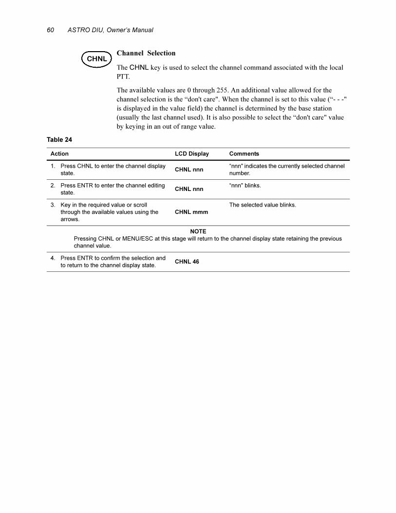
60 ASTRO DIU, Owner’s Manual
Channel Selection
The CHNL key is used to select the channel command associated with the local
PTT.
The available values are 0 through 255. An additional value allowed for the
channel selection is the “don't care". When the channel is set to this value (“- - -"
is displayed in the value field) the channel is determined by the base station
(usually the last channel used). It is also possible to select the “don't care" value
by keying in an out of range value.
CHNL
Table 24
Action LCD Display Comments
1. Press CHNL to enter the channel display
state.CHNL nnn
“nnn" indicates the currently selected channel
number.
2. Press ENTR to enter the channel editing
state.CHNL nnn
“nnn" blinks.
3. Key in the required value or scroll
through the available values using the
arrows.
CHNL mmm
The selected value blinks.
NOTE
Pressing CHNL or MENU/ESC at this stage will return to the channel display state retaining the previous
channel value.
4. Press ENTR to confirm the selection and
to return to the channel display state.CHNL 46
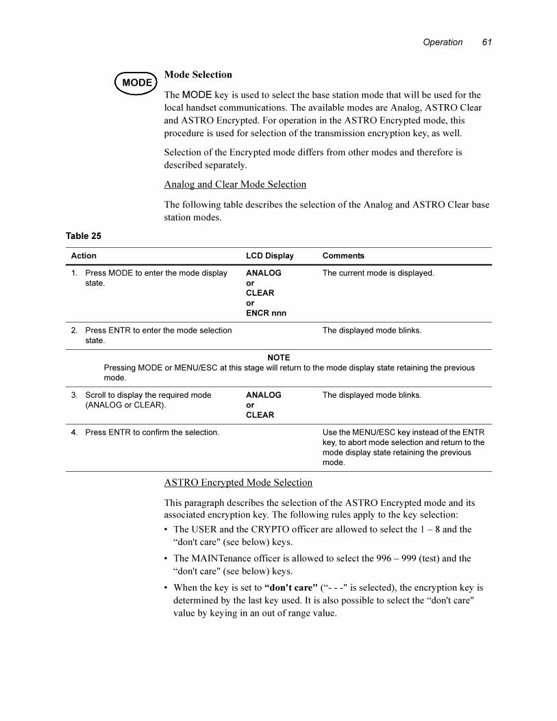
Operation 61
Mode Selection
The MODE key is used to select the base station mode that will be used for the
local handset communications. The available modes are Analog, ASTRO Clear
and ASTRO Encrypted. For operation in the ASTRO Encrypted mode, this
procedure is used for selection of the transmission encryption key, as well.
Selection of the Encrypted mode differs from other modes and therefore is
described separately.
Analog and Clear Mode Selection
The following table describes the selection of the Analog and ASTRO Clear base
station modes.
ASTRO Encrypted Mode Selection
This paragraph describes the selection of the ASTRO Encrypted mode and its
associated encryption key. The following rules apply to the key selection:
• The USER and the CRYPTO officer are allowed to select the 1 – 8 and the
“don't care" (see below) keys.
• The MAINTenance officer is allowed to select the 996 – 999 (test) and the
“don't care" (see below) keys.
• When the key is set to “don't care" (“- - -" is selected), the encryption key is
determined by the last key used. It is also possible to select the “don't care"
value by keying in an out of range value.
MODE
Table 25
Action LCD Display Comments
1. Press MODE to enter the mode display
state.
ANALOG
or
CLEAR
or
ENCR nnn
The current mode is displayed.
2. Press ENTR to enter the mode selection
state.
The displayed mode blinks.
NOTE
Pressing MODE or MENU/ESC at this stage will return to the mode display state retaining the previous
mode.
3. Scroll to display the required mode
(ANALOG or CLEAR).
ANALOG
or
CLEAR
The displayed mode blinks.
4. Press ENTR to confirm the selection. Use the MENU/ESC key instead of the ENTR
key, to abort mode selection and return to the
mode display state retaining the previous
mode.
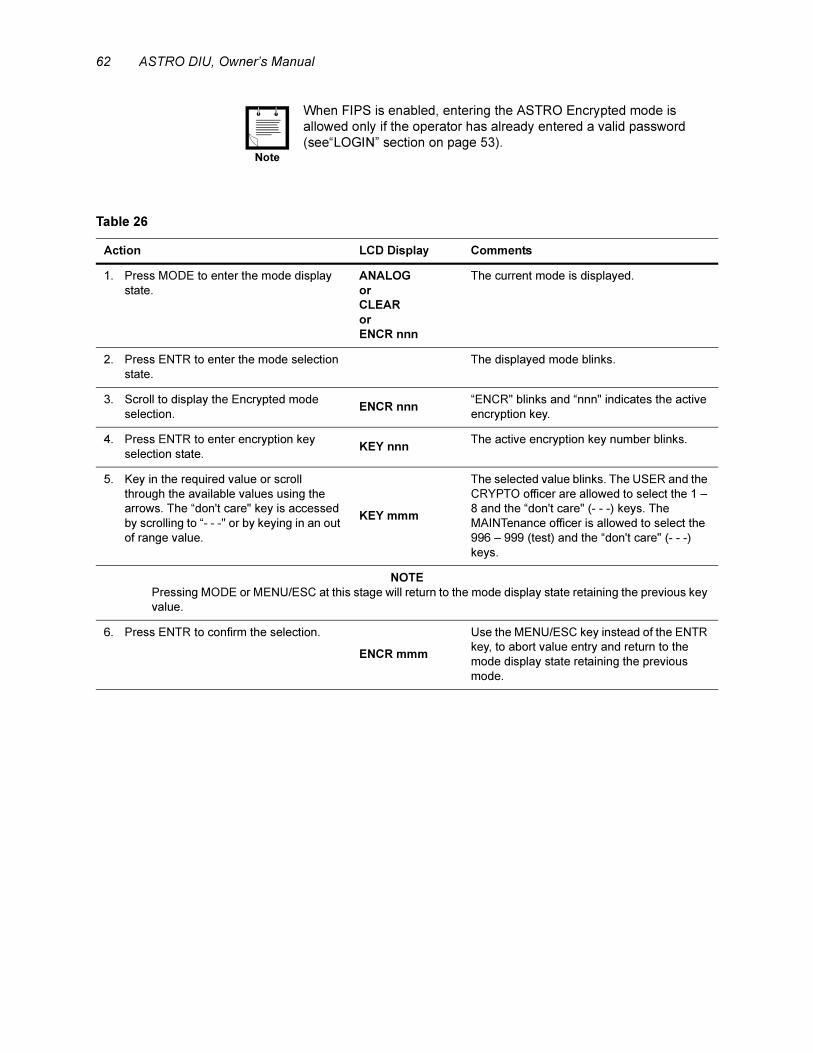
62 ASTRO DIU, Owner’s Manual
.
When FIPS is enabled, entering the ASTRO Encrypted mode is
allowed only if the operator has already entered a valid password
(see“LOGIN” section on page 53).Note
Table 26
Action LCD Display Comments
1. Press MODE to enter the mode display
state.
ANALOG
or
CLEAR
or
ENCR nnn
The current mode is displayed.
2. Press ENTR to enter the mode selection
state.
The displayed mode blinks.
3. Scroll to display the Encrypted mode
selection.ENCR nnn
“ENCR" blinks and “nnn" indicates the active
encryption key.
4. Press ENTR to enter encryption key
selection state.KEY nnn
The active encryption key number blinks.
5. Key in the required value or scroll
through the available values using the
arrows. The “don't care" key is accessed
by scrolling to “- - -" or by keying in an out
of range value.
KEY mmm
The selected value blinks. The USER and the
CRYPTO officer are allowed to select the 1 –
8 and the “don't care" (- - -) keys. The
MAINTenance officer is allowed to select the
996 – 999 (test) and the “don't care" (- - -)
keys.
NOTE
Pressing MODE or MENU/ESC at this stage will return to the mode display state retaining the previous key
value.
6. Press ENTR to confirm the selection.
ENCR mmm
Use the MENU/ESC key instead of the ENTR
key, to abort value entry and return to the
mode display state retaining the previous
mode.
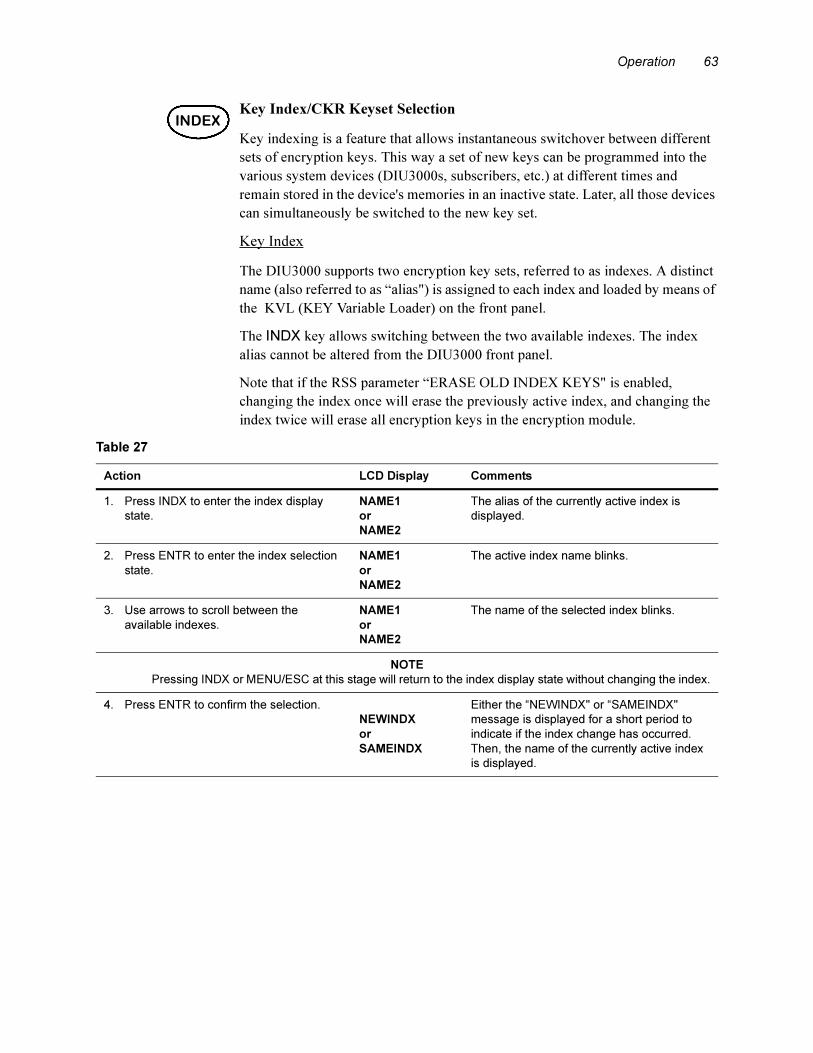
Operation 63
Key Index/CKR Keyset Selection
Key indexing is a feature that allows instantaneous switchover between different
sets of encryption keys. This way a set of new keys can be programmed into the
various system devices (DIU3000s, subscribers, etc.) at different times and
remain stored in the device's memories in an inactive state. Later, all those devices
can simultaneously be switched to the new key set.
Key Index
The DIU3000 supports two encryption key sets, referred to as indexes. A distinct
name (also referred to as “alias") is assigned to each index and loaded by means of
the KVL (KEY Variable Loader) on the front panel.
The INDX key allows switching between the two available indexes. The index
alias cannot be altered from the DIU3000 front panel.
Note that if the RSS parameter “ERASE OLD INDEX KEYS" is enabled,
changing the index once will erase the previously active index, and changing the
index twice will erase all encryption keys in the encryption module.
INDEX
Table 27
Action LCD Display Comments
1. Press INDX to enter the index display
state.
NAME1
or
NAME2
The alias of the currently active index is
displayed.
2. Press ENTR to enter the index selection
state.
NAME1
or
NAME2
The active index name blinks.
3. Use arrows to scroll between the
available indexes.
NAME1
or
NAME2
The name of the selected index blinks.
NOTE
Pressing INDX or MENU/ESC at this stage will return to the index display state without changing the index.
4. Press ENTR to confirm the selection.
NEWINDX
or
SAMEINDX
Either the “NEWINDX" or “SAMEINDX"
message is displayed for a short period to
indicate if the index change has occurred.
Then, the name of the currently active index
is displayed.
64 ASTRO DIU, Owner’s Manual
CKR Keyset
For APCO key management configurations, the DIU3000 supports numerous
keysets. The keysets provide for functionality similar to Indexing.
Volume Control
The [^] and [|] arrows on the DIU3000 keypad can control the volume of the
handset speaker. To do so, the DIU3000 should be in one of the following states:
– Time of day display state
– Function request (FREQ) display state
– Mode display state
– Channel display state
– Index display state
The [^] arrow increases the volume, while the [|] arrow decreases the volume.
There are 10 available volume levels, designated 0 through 9.
When either of the arrows is pressed, the volume is adjusted and the updated
volume level is displayed on the LCD (e.g., VOL X, where “x" indicates the updated
volume level).
Transmission
The DIU3000 PTT is used to key in the base station. The transmission includes
ASTRO signalling, determined by parameters set from the DIU3000 front panel
via the direct access keys, as described in the previous sections. Note that these
parameters are stored in a memory backed up by a battery, so that they are
retained after the DIU3000 has been turned off and on.
When the Link Busy LED is lit, transmission is inhibited. During transmission,
the Transmit LED is lit.
.
Table 28
Action LCD Display Comments
1. Press INDX to display the active keyset.
2. Press ENTER to enter the keyset
selection state.
3. Use arrows to scroll between the
available keysets.
Active keysets will be blinking. Inactive
keysets will be solid.
4. Press ENTER to select and make the
keyset active.
The DIU3000 can be programmed by the RSS to issue an alert tone to
the console, to indicate transmission in clear mode when the encrypted
mode is enabled.Note

Operation 65
Encryption Key Erasure
The ERSE direct access function key enables erasing (zeroization) of all traffic
encryption keys in the encryption module via the DIU3000 keypad. For CKR and
OTAR configurations, all key encryption keys will also be erased. However, if the
Key Loss Key feature is enabled, the key loss key will not be erased.
.
Monitor
Pressing the monitor key on the DIU3000 front panel allows unsquelching and
monitoring the receive path.
The DIU3000 can be programmed by the RSS to issue an alert tone to
the console, to indicate key zeroization.
Note
Table 29
Action LCD Display Comments
1. Press the ERSE key to enter the key
zeroization function. KEYERSE
The prompt indicates that the key
zeroization function is active and the LED
on the ERSE key is lit.
NOTE
Pressing ERSE or MENU/ESC at this stage will exit the key zeroization function without performing the
zeroization.
2. Press ENTR to initiate the zeroization
procedure.
ZEROIZED
The LED on the ERSE key goes off and
the “ZEROIZED" prompt is shown for
several seconds to indicate successful
zeroization. The DIU3000 then returns to
the ready state.

66 ASTRO DIU, Owner’s Manual
Troubleshooting
General Checks
In case of malfunctioning, and before consulting the troubleshooting procedures,
verify the following:
• The ac power cable and all the other cables are firmly connected to the unit.
• The encryption cartridge is properly installed (if present).
• The DIU3000 has been appropriately programmed by the RSS.

Troubleshooting 67
General Indications
Table 30
Problem / Indication Possible Cause Remedy
Power–on self–test reports
“TST FAIL".
DIU3000 internal failure. Refer to “Information and Error
Messages”.
Link Busy LED is on. The link establishment between the
DIU3000 and the Base Station is in
progress. This indication is normal if it
appears immediately after the power–on
sequence and lasts for about
30 seconds.
If still on after 30 seconds, then check
the connection to the Base Station/
Comparator. Check the connectors, line,
Base Station or the Comparator
functionality (either Modem link or V.24
link).
Link Busy LED is flashing. The link establishment between the
DIU3000 and the RNC is in progress.
This indication is normal if it appears
immediately after the power–on
sequence and lasts for about
30 seconds.
Battery LED is on. No ac power (DIU3000 operates from
external backup battery).
Connect DIU3000 to ac power.
Battery LED is flashing. Low voltage problem. Refer to “Information and Error
Messages”.
The transmission fails. 1. The link is busy (Link Busy LED is
lit).
Wait till the Link Busy LED goes off.
2. Tone1 and Tone2 frequencies of a
dual tone TRC command are
identical.
Use RSS to correct the frequency values
of the particular FREQ.
3. The encrypted session has not been
opened.
Login into an encrypted session.
4. Trial to transmit in encrypted mode,
while the encryption cartridge is not
properly installed or not installed at
all.
Verify that the encryption cartridge is
present and properly installed.
5. Trial to transmit with an encryption
key that is not loaded.
Load the required encryption key using
KVL or if possible, use another key.
“BAD EPRM" message on
the LCD.
Internal memory failure. Have the unit serviced.
“BAD FLSH" message on
the LCD.
Internal memory failure. Have the unit serviced.
“BAD RAM" message on
the LCD.
Internal memory failure. Have the unit serviced.
“ERSE ERR" message on
the LCD.
The key erase operation has failed. Verify that the encryption cartridge is
properly installed.
“LOG FAIL" message on
the LCD.
The logout operation has failed. Verify that the encryption cartridge is
properly installed.
“PWR LOW" message on
the LCD.
Low voltage problem. Refer to “Information and Error
Messages”.
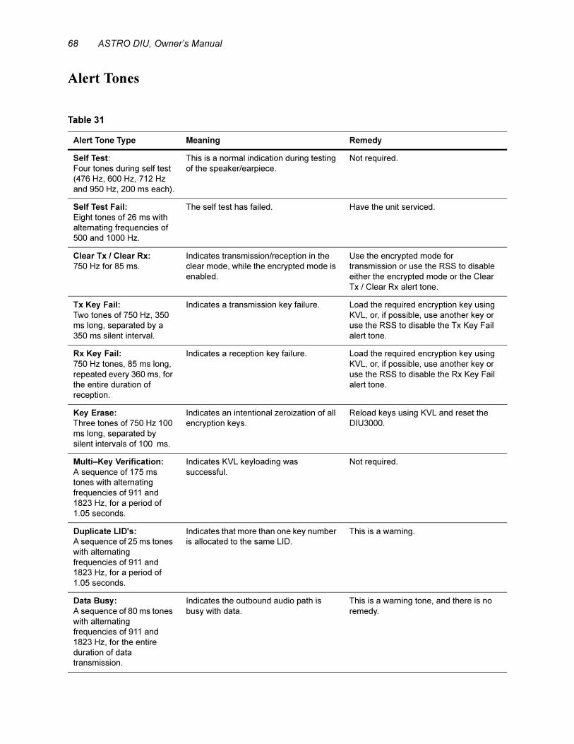
68 ASTRO DIU, Owner’s Manual
Alert Tones
Table 31
Alert Tone Type Meaning Remedy
Self Test:
Four tones during self test
(476 Hz, 600 Hz, 712 Hz
and 950 Hz, 200 ms each).
This is a normal indication during testing
of the speaker/earpiece.
Not required.
Self Test Fail:
Eight tones of 26 ms with
alternating frequencies of
500 and 1000 Hz.
The self test has failed. Have the unit serviced.
Clear Tx / Clear Rx:
750 Hz for 85 ms.
Indicates transmission/reception in the
clear mode, while the encrypted mode is
enabled.
Use the encrypted mode for
transmission or use the RSS to disable
either the encrypted mode or the Clear
Tx / Clear Rx alert tone.
Tx Key Fail:
Two tones of 750 Hz, 350
ms long, separated by a
350 ms silent interval.
Indicates a transmission key failure. Load the required encryption key using
KVL, or, if possible, use another key or
use the RSS to disable the Tx Key Fail
alert tone.
Rx Key Fail:
750 Hz tones, 85 ms long,
repeated every 360 ms, for
the entire duration of
reception.
Indicates a reception key failure. Load the required encryption key using
KVL, or, if possible, use another key or
use the RSS to disable the Rx Key Fail
alert tone.
Key Erase:
Three tones of 750 Hz 100
ms long, separated by
silent intervals of 100 ms.
Indicates an intentional zeroization of all
encryption keys.
Reload keys using KVL and reset the
DIU3000.
Multi–Key Verification:
A sequence of 175 ms
tones with alternating
frequencies of 911 and
1823 Hz, for a period of
1.05 seconds.
Indicates KVL keyloading was
successful.
Not required.
Duplicate LID's:
A sequence of 25 ms tones
with alternating
frequencies of 911 and
1823 Hz, for a period of
1.05 seconds.
Indicates that more than one key number
is allocated to the same LID.
This is a warning.
Data Busy:
A sequence of 80 ms tones
with alternating
frequencies of 911 and
1823 Hz, for the entire
duration of data
transmission.
Indicates the outbound audio path is
busy with data.
This is a warning tone, and there is no
remedy.
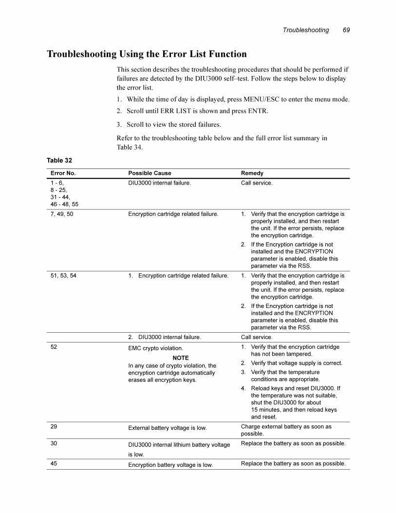
Troubleshooting 69
Troubleshooting Using the Error List Function
This section describes the troubleshooting procedures that should be performed if
failures are detected by the DIU3000 self–test. Follow the steps below to display
the error list.
1. While the time of day is displayed, press MENU/ESC to enter the menu mode.
2. Scroll until ERR LIST is shown and press ENTR.
3. Scroll to view the stored failures.
Refer to the troubleshooting table below and the full error list summary in
Table 34.
Table 32
Error No. Possible Cause Remedy
1 - 6,
8 - 25,
31 - 44,
46 - 48, 55
DIU3000 internal failure. Call service.
7, 49, 50 Encryption cartridge related failure. 1. Verify that the encryption cartridge is
properly installed, and then restart
the unit. If the error persists, replace
the encryption cartridge.
2. If the Encryption cartridge is not
installed and the ENCRYPTION
parameter is enabled, disable this
parameter via the RSS.
51, 53, 54 1. Encryption cartridge related failure. 1. Verify that the encryption cartridge is
properly installed, and then restart
the unit. If the error persists, replace
the encryption cartridge.
2. If the Encryption cartridge is not
installed and the ENCRYPTION
parameter is enabled, disable this
parameter via the RSS.
2. DIU3000 internal failure. Call service.
52 EMC crypto violation.
NOTE
In any case of crypto violation, the
encryption cartridge automatically
erases all encryption keys.
1. Verify that the encryption cartridge
has not been tampered.
2. Verify that voltage supply is correct.
3. Verify that the temperature
conditions are appropriate.
4. Reload keys and reset DIU3000. If
the temperature was not suitable,
shut the DIU3000 for about
15 minutes, and then reload keys
and reset.
29 External battery voltage is low. Charge external battery as soon as
possible.
30 DIU3000 internal lithium battery voltage
is low.
Replace the battery as soon as possible.
45 Encryption battery voltage is low. Replace the battery as soon as possible.
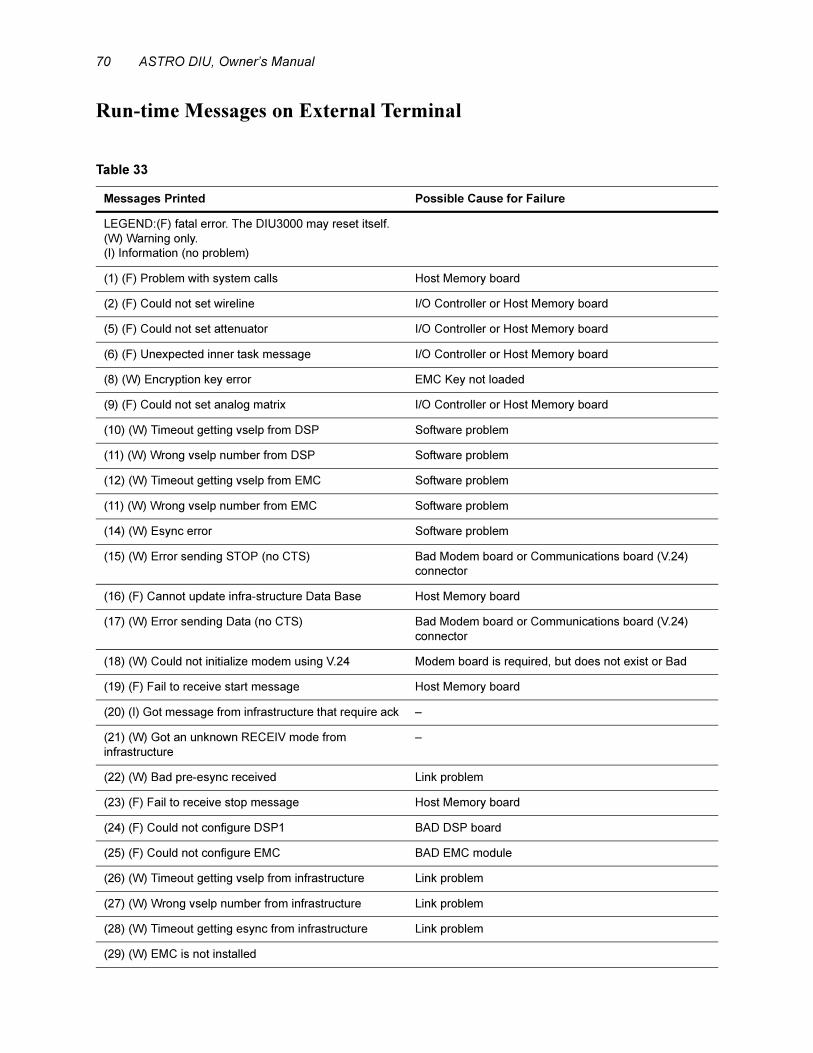
70 ASTRO DIU, Owner’s Manual
Run-time Messages on External Terminal
Table 33
Messages Printed Possible Cause for Failure
LEGEND:(F) fatal error. The DIU3000 may reset itself.
(W) Warning only.
(I) Information (no problem)
(1) (F) Problem with system calls Host Memory board
(2) (F) Could not set wireline I/O Controller or Host Memory board
(5) (F) Could not set attenuator I/O Controller or Host Memory board
(6) (F) Unexpected inner task message I/O Controller or Host Memory board
(8) (W) Encryption key error EMC Key not loaded
(9) (F) Could not set analog matrix I/O Controller or Host Memory board
(10) (W) Timeout getting vselp from DSP Software problem
(11) (W) Wrong vselp number from DSP Software problem
(12) (W) Timeout getting vselp from EMC Software problem
(11) (W) Wrong vselp number from EMC Software problem
(14) (W) Esync error Software problem
(15) (W) Error sending STOP (no CTS) Bad Modem board or Communications board (V.24)
connector
(16) (F) Cannot update infra-structure Data Base Host Memory board
(17) (W) Error sending Data (no CTS) Bad Modem board or Communications board (V.24)
connector
(18) (W) Could not initialize modem using V.24 Modem board is required, but does not exist or Bad
(19) (F) Fail to receive start message Host Memory board
(20) (I) Got message from infrastructure that require ack –
(21) (W) Got an unknown RECEIV mode from
infrastructure
–
(22) (W) Bad pre-esync received Link problem
(23) (F) Fail to receive stop message Host Memory board
(24) (F) Could not configure DSP1 BAD DSP board
(25) (F) Could not configure EMC BAD EMC module
(26) (W) Timeout getting vselp from infrastructure Link problem
(27) (W) Wrong vselp number from infrastructure Link problem
(28) (W) Timeout getting esync from infrastructure Link problem
(29) (W) EMC is not installed
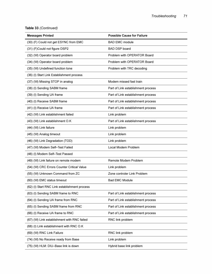
Troubleshooting 71
(30) (F) Could not get ESYNC from EMC BAD EMC module
(31) (F)Could not figure DSP2 BAD DSP board
(32) (W) Operator board problem Problem with OPERATOR Board
(34) (W) Operator board problem Problem with OPERATOR Board
(35) (W) Undefined function tone Problem with TRC decoding
(36) (I) Start Link Establishment process
(37) (W) Missing STOP in analog Modem missed fast train
(38) (I) Sending SABM frame Part of Link establishment process
(39) (I) Sending UA frame Part of Link establishment process
(40) (I) Receive SABM frame Part of Link establishment process
(41) (I) Receive UA frame Part of Link establishment process
(42) (W) Link establishment failed Link problem
(43) (W) Link establishment O.K Part of Link establishment process
(44) (W) Link failure Link problem
(45) (W) Analog timeout Link problem
(46) (W) Link Degradation (TOD) Link problem
(47) (W) Modem Self–Test Failed Local Modem Problem
(48) (I) Modem Self–Test Passed
(49) (W) Link failure on remote modem Remote Modem Problem
(54) (W) CRC Errors Counter Critical Value Link problem
(55) (W) Unknown Command from ZC Zone controler Link Problem
(60) (W) EMC status timeout Bad EMC Module
(62) (I) Start RNC Link establishment process
(63) (I) Sending SABM frame to RNC Part of Link establishment process
(64) (I) Sending UA frame from RNC Part of Link establishment process
(65) (I) Sending SABM frame from RNC Part of Link establishment process
(66) (I) Receive UA frame to RNC Part of Link establishment process
(67) (W) Link establishment with RNC failed RNC link problem
(68) (I) Link establishment with RNC O.K
(69) (W) RNC Link Failure RNC link problem
(74) (W) No Receive ready from Base Link problem
(75) (W) HLM: DIU–Base link is down Hybrid base link problem
Table 33 (Continued)
Messages Printed Possible Cause for Failure
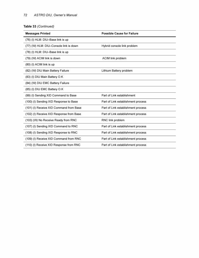
72 ASTRO DIU, Owner’s Manual
(76) (I) HLM: DIU–Base link is up
(77) (W) HLM: DIU–Console link is down Hybrid console link problem
(78) (I) HLM: DIU–Base link is up
(79) (W) ACIM link is down ACIM link problem
(80) (I) ACIM link is up
(82) (W) DIU Main Battery Failure Lithium Battery problem
(83) (I) DIU Main Battery O.K
(84) (W) DIU EMC Battery Failure
(85) (I) DIU EMC Battery O.K
(99) (I) Sending XID Command to Base Part of Link establishment
(100) (I) Sending XID Response to Base Part of Link establishment process
(101) (I) Receive XID Command from Base Part of Link establishment process
(102) (I) Receive XID Response from Base Part of Link establishment process
(103) (W) No Receive Ready from RNC RNC link problem
(107) (I) Sending XID Command to RNC Part of Link establishment process
(108) (I) Sending XID Response to RNC Part of Link establishment process
(109) (I) Receive XID Command from RNC Part of Link establishment process
(110) (I) Receive XID Response from RNC Part of Link establishment process
Table 33 (Continued)
Messages Printed Possible Cause for Failure
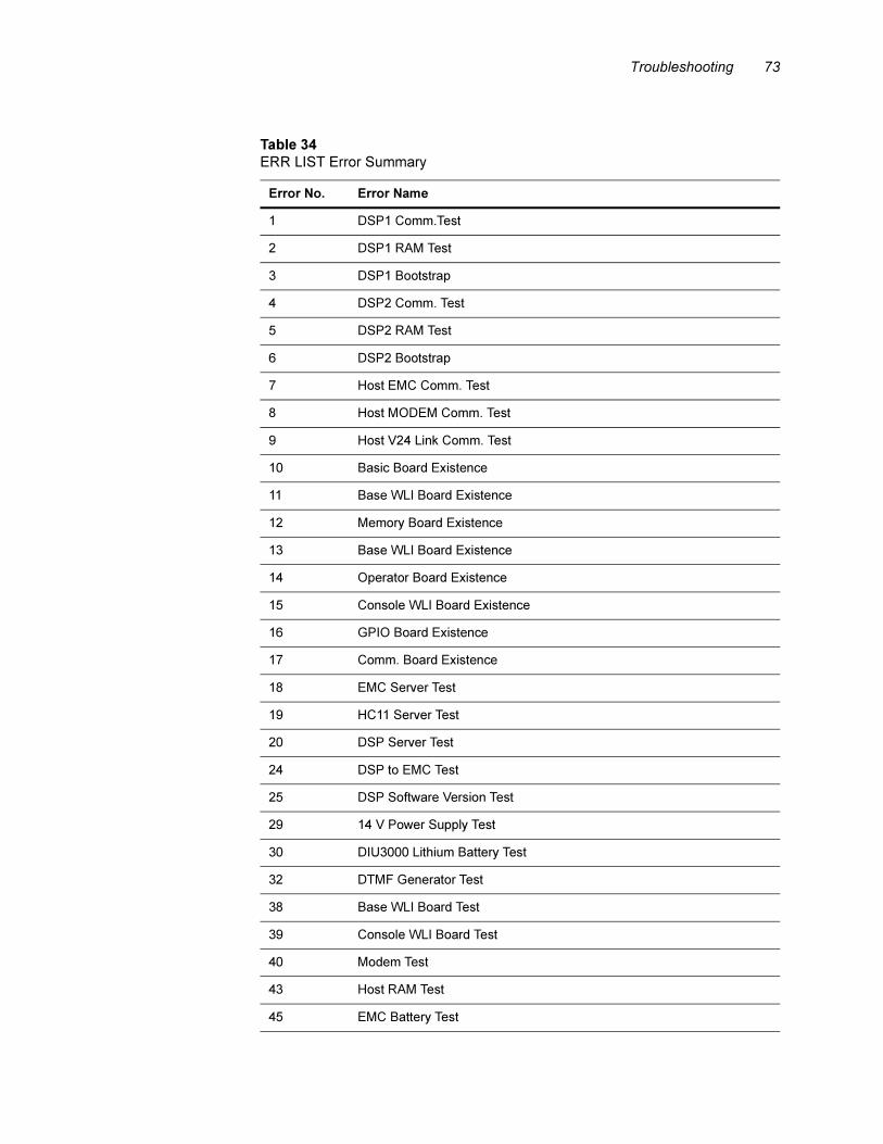
Troubleshooting 73
Table 34
ERR LIST Error Summary
Error No. Error Name
1 DSP1 Comm.Test
2 DSP1 RAM Test
3 DSP1 Bootstrap
4 DSP2 Comm. Test
5 DSP2 RAM Test
6 DSP2 Bootstrap
7 Host EMC Comm. Test
8 Host MODEM Comm. Test
9 Host V24 Link Comm. Test
10 Basic Board Existence
11 Base WLI Board Existence
12 Memory Board Existence
13 Base WLI Board Existence
14 Operator Board Existence
15 Console WLI Board Existence
16 GPIO Board Existence
17 Comm. Board Existence
18 EMC Server Test
19 HC11 Server Test
20 DSP Server Test
24 DSP to EMC Test
25 DSP Software Version Test
29 14 V Power Supply Test
30 DIU3000 Lithium Battery Test
32 DTMF Generator Test
38 Base WLI Board Test
39 Console WLI Board Test
40 Modem Test
43 Host RAM Test
45 EMC Battery Test
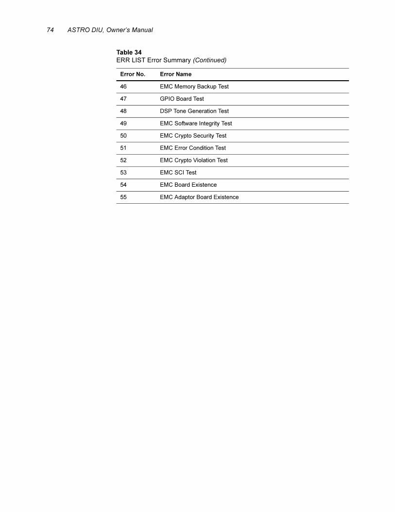
74 ASTRO DIU, Owner’s Manual
46 EMC Memory Backup Test
47 GPIO Board Test
48 DSP Tone Generation Test
49 EMC Software Integrity Test
50 EMC Crypto Security Test
51 EMC Error Condition Test
52 EMC Crypto Violation Test
53 EMC SCI Test
54 EMC Board Existence
55 EMC Adaptor Board Existence
Table 34
ERR LIST Error Summary (Continued)
Error No. Error Name
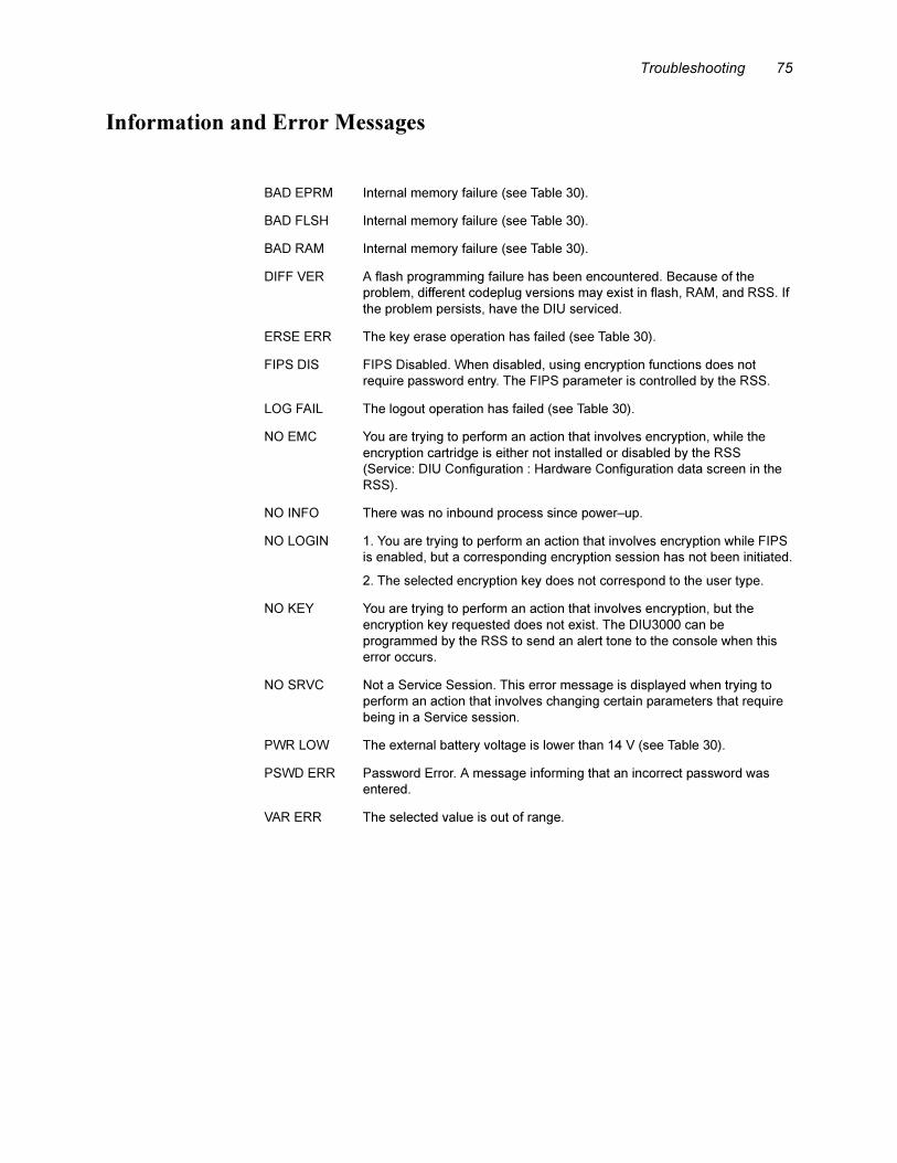
Troubleshooting 75
Information and Error Messages
BAD EPRM Internal memory failure (see Table 30).
BAD FLSH Internal memory failure (see Table 30).
BAD RAM Internal memory failure (see Table 30).
DIFF VER A flash programming failure has been encountered. Because of the
problem, different codeplug versions may exist in flash, RAM, and RSS. If
the problem persists, have the DIU serviced.
ERSE ERR The key erase operation has failed (see Table 30).
FIPS DIS FIPS Disabled. When disabled, using encryption functions does not
require password entry. The FIPS parameter is controlled by the RSS.
LOG FAIL The logout operation has failed (see Table 30).
NO EMC You are trying to perform an action that involves encryption, while the
encryption cartridge is either not installed or disabled by the RSS
(Service: DIU Configuration : Hardware Configuration data screen in the
RSS).
NO INFO There was no inbound process since power–up.
NO LOGIN 1. You are trying to perform an action that involves encryption while FIPS
is enabled, but a corresponding encryption session has not been initiated.
2. The selected encryption key does not correspond to the user type.
NO KEY You are trying to perform an action that involves encryption, but the
encryption key requested does not exist. The DIU3000 can be
programmed by the RSS to send an alert tone to the console when this
error occurs.
NO SRVC Not a Service Session. This error message is displayed when trying to
perform an action that involves changing certain parameters that require
being in a Service session.
PWR LOW The external battery voltage is lower than 14 V (see Table 30).
PSWD ERR Password Error. A message informing that an incorrect password was
entered.
VAR ERR The selected value is out of range.
76 ASTRO DIU, Owner’s Manual
DIU3000 Functional Tests
General
The DIU3000 is a full duplex device, that allows establishing a link with itself by
interconnecting the transmit and receive lines on the DIU3000 rear panel
connectors. The following sections provide instructions on performing such tests
for fault isolation purposes during system problems.
It is possible to disconnect the base station and create a direct connection between
the DIU3000 transmit and receive terminals to/from the base station. This enables
the DIU3000 functional operation to be checked in all modes of operation. Refer
to section “Testing the DIU3000 with Loop–Back on Base Station” below.
An additional test requires placing the DIU3000 in a special test mode. In this
mode, it is possible to completely disconnect it from the outside world (both from
the base station and the console), and functionally test about 99% of the DIU3000
hardware. Refer to section “DIU Stand Alone Audio Loop Test” on page 78.
Testing the DIU3000 with Loop–Back on Base Station.
This test allows testing the DIU3000 functional operation without connecting it to
the base station. Perform the following setup (see Figure 14):
• For the Modem analog link (option X437AF): connect jumper wires between
the T/R and R terminals of the “STATION" connector.
• For the V.24 Digital link: connect jumper wires between the following pins of
the “COMM" connector: 2 (TD) and 3 (RD), 24 (TCLK) and 17 (RCLK),
4 (RTS), 5 (CTS) and 8 (CD). Connect jumper wires between the T/R and R
terminals of the “STATION" connector.
Use the DIU3000 handset to speak and monitor your voice (with some delay).
Only if the DIU3000 circuits function properly, will you hear your voice through
the handset earpiece. You can perform the test in all the modes of operation.
Use the analog console handset in full duplex mode to speak and monitor your
voice (with some delay). Only if the DIU3000 circuits function properly, will you
hear your voice through the handset earpiece. You can perform the test in all
modes of operation.
The Audio Loop test requires the use of a test handset (option
C109AA).
Note

Troubleshooting 77
.
Figure 14
Testing the DIU3000 with Loop-Back on Base Station
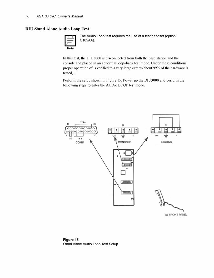
78 ASTRO DIU, Owner’s Manual
DIU Stand Alone Audio Loop Test.
In this test, the DIU3000 is disconnected from both the base station and the
console and placed in an abnormal loop–back test mode. Under these conditions,
proper operation of is verified to a very large extent (about 99% of the hardware is
tested).
Perform the setup shown in Figure 15. Power up the DIU3000 and perform the
following steps to enter the AUDio LOOP test mode.
.
The Audio Loop test requires the use of a test handset (option
C109AA).
Figure 15
Stand Alone Audio Loop Test Setup
Note
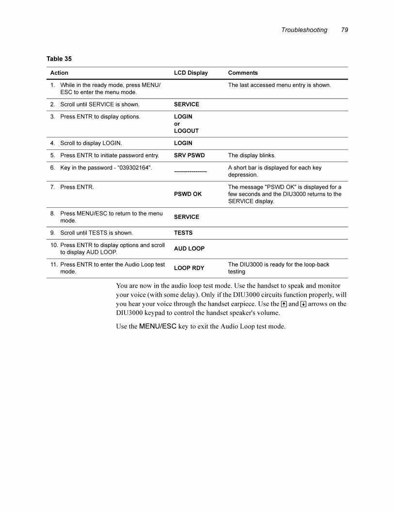
Troubleshooting 79
You are now in the audio loop test mode. Use the handset to speak and monitor
your voice (with some delay). Only if the DIU3000 circuits function properly, will
you hear your voice through the handset earpiece. Use the [^] and [|] arrows on the
DIU3000 keypad to control the handset speaker's volume.
Use the MENU/ESC key to exit the Audio Loop test mode.
Table 35
Action LCD Display Comments
1. While in the ready mode, press MENU/
ESC to enter the menu mode.
The last accessed menu entry is shown.
2. Scroll until SERVICE is shown. SERVICE
3. Press ENTR to display options. LOGIN
or
LOGOUT
4. Scroll to display LOGIN. LOGIN
5. Press ENTR to initiate password entry. SRV PSWD The display blinks.
6. Key in the password - “039302164".-----------------
A short bar is displayed for each key
depression.
7. Press ENTR.
PSWD OK
The message "PSWD OK" is displayed for a
few seconds and the DIU3000 returns to the
SERVICE display.
8. Press MENU/ESC to return to the menu
mode.SERVICE
9. Scroll until TESTS is shown. TESTS
10. Press ENTR to display options and scroll
to display AUD LOOP.AUD LOOP
11. Press ENTR to enter the Audio Loop test
mode.LOOP RDY
The DIU3000 is ready for the loop-back
testing

80 ASTRO DIU, Owner’s Manual
APPENDIXES
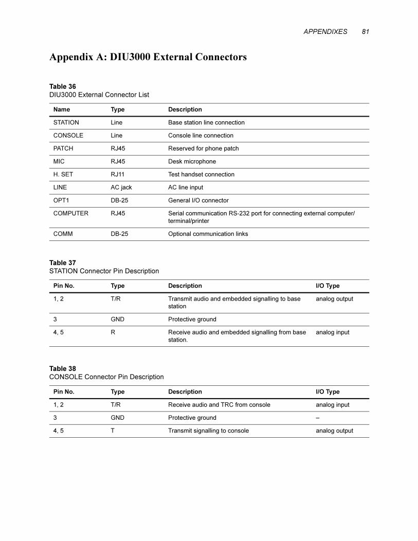
APPENDIXES 81
Appendix A: DIU3000 External Connectors
Table 36
DIU3000 External Connector List
Name Type Description
STATION Line Base station line connection
CONSOLE Line Console line connection
PATCH RJ45 Reserved for phone patch
MIC RJ45 Desk microphone
H. SET RJ11 Test handset connection
LINE AC jack AC line input
OPT1 DB-25 General I/O connector
COMPUTER RJ45 Serial communication RS-232 port for connecting external computer/
terminal/printer
COMM DB-25 Optional communication links
Table 37
STATION Connector Pin Description
Pin No. Type Description I/O Type
1, 2 T/R Transmit audio and embedded signalling to base
station
analog output
3 GND Protective ground
4, 5 R Receive audio and embedded signalling from base
station.
analog input
Table 38
CONSOLE Connector Pin Description
Pin No. Type Description I/O Type
1, 2 T/R Receive audio and TRC from console analog input
3 GND Protective ground –
4, 5 T Transmit signalling to console analog output

82 ASTRO DIU, Owner’s Manual
Figure 16
DIU3000 Interface Diagram

APPENDIXES 83
.
Table 39
H. SET Connector Pin Description
Pin No. Description I/O Type
1 Ground –
2 PTT and On/Off hook indication analog input
3 Earpiece analog output
4 Microphone analog input
Table 40
OPT. 1 (General Purpose I/O) Connector Pin Description
Pin
No.Description I/O Type Logic Low =
Junction Box
Corresponding Pin
No.*(option C62AB)
1 Receiver unsquelch to Centracom console logic output† Unsquelch‡ TB4–2
2 Not used
3 Not used
4 Digital ground TB4–3
5 Repeat disable logic input
6 PTT logic input
7 M_LEAD logic output† PTT active TB2–1
8 SEL-1
9 SEL-2
10 Not used
11 Not used
12 External speaker analog output TB5–5
13 External battery (+) power input TB5–6
14 Not used
15 Not used
16 Not used
17 Not used
18 Not used
19 Analog GND
20 Not used
21 Mode indication logic output† Mode 1‡ TB4–1
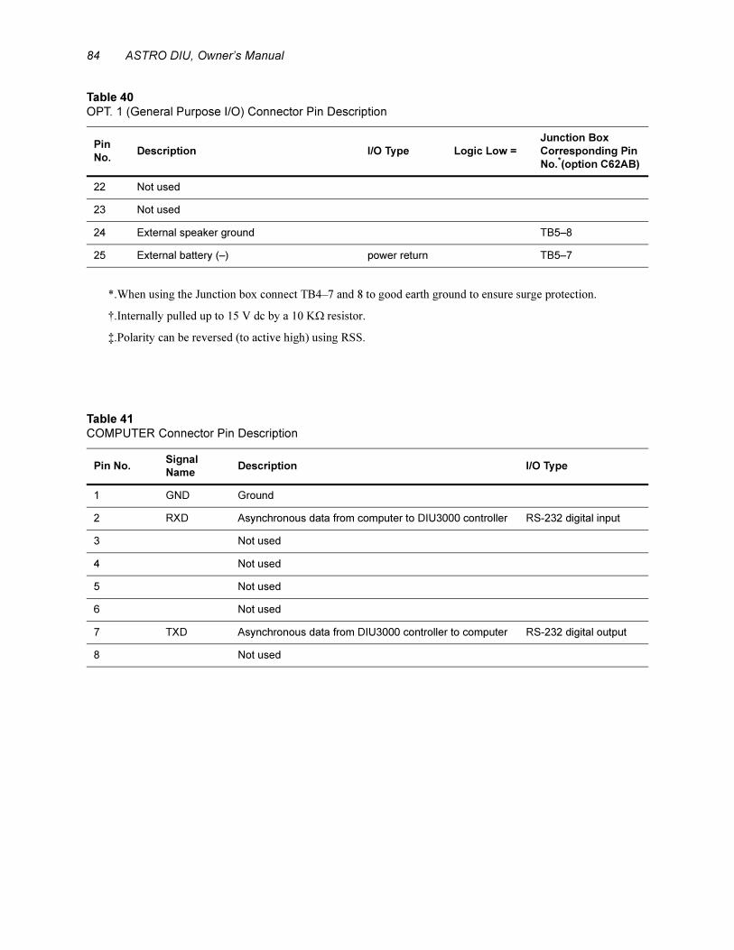
84 ASTRO DIU, Owner’s Manual
22 Not used
23 Not used
24 External speaker ground TB5–8
25 External battery (–) power return TB5–7
*.When using the Junction box connect TB4–7 and 8 to good earth ground to ensure surge protection.
†.Internally pulled up to 15 V dc by a 10 K� resistor.
‡.Polarity can be reversed (to active high) using RSS.
Table 40
OPT. 1 (General Purpose I/O) Connector Pin Description
Pin
No.Description I/O Type Logic Low =
Junction Box
Corresponding Pin
No.*(option C62AB)
Table 41
COMPUTER Connector Pin Description
Pin No.Signal
NameDescription I/O Type
1 GND Ground
2 RXD Asynchronous data from computer to DIU3000 controller RS-232 digital input
3 Not used
4 Not used
5 Not used
6 Not used
7 TXD Asynchronous data from DIU3000 controller to computer RS-232 digital output
8 Not used
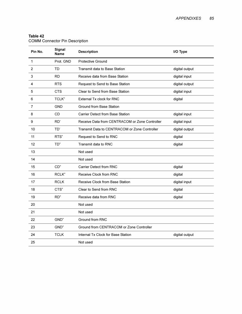
APPENDIXES 85
Table 42
COMM Connector Pin Description
Pin No.Signal
NameDescription I/O Type
1 Prot. GND Protective Ground
2 TD Transmit data to Base Station digital output
3 RD Receive data from Base Station digital input
4 RTS Request to Send to Base Station digital output
5 CTS Clear to Send from Base Station digital input
6 TCLK” External Tx clock for RNC digital
7 GND Ground from Base Station
8 CD Carrier Detect from Base Station digital input
9 RD’ Receive Data from CENTRACOM or Zone Controller digital input
10 TD’ Transmit Data to CENTRACOM or Zone Controller digital output
11 RTS” Request to Send to RNC digital
12 TD” Transmit data to RNC digital
13 Not used
14 Not used
15 CD” Carrier Detect from RNC digital
16 RCLK” Receive Clock from RNC digital
17 RCLK Receive Clock from Base Station digital input
18 CTS” Clear to Send from RNC digital
19 RD” Receive data from RNC digital
20 Not used
21 Not used
22 GND” Ground from RNC
23 GND” Ground from CENTRACOM or Zone Controller
24 TCLK Internal Tx Clock for Base Station digital output
25 Not used

86 ASTRO DIU, Owner’s Manual
.
Table 43
Quad Connector FLN5462A Pin Description
FunctionDIU Comm Port
DB-25M PIN
V.24 (null)
RJ-45 #1
V.24
RJ-45 #2
ACIM/SZ
RJ-45 #3
RNC
RJ-45 #4
PROT. GND 1
TD 2 5 6
RD 3 6 5
RTS 4 2 8
CTS Jmpr #4 DB25-5
to DB25-4 &
DB25-5 to Jmpr
#6-1
7
TCLK” 6 1
SIG GND 7 4 4
CD DB25-8 to
Jmpr #6-2
RJ#1-8 to
Jmpr #6-3
RJ#2-2 to
Jmpr #6-3
RD’ 9 Jmpr #2 DB25-9 to
RJ#3-3 & DB25-9
to RJ#3-4
TD’ 10 Jmpr #3 DB25-10
to RJ#3-2 & DB25-
10 to RJ#3-6
RTS” 11 6
TD” 12 2
Not used 13
Not used 14
CD” Jmpr #5 DB25-
15 to DB25-11
RCLK” 16 3
RCLK” 17 3 1
CTS” 18 7
RD” 19 5
Not used 20
Not used 21
GND” 22 4
GND” 23 Jmpr #1 DB25-23
to RJ#3-7 & DB25-
23 to RJ#3-8
TCLK 24 1 3
Not used 25
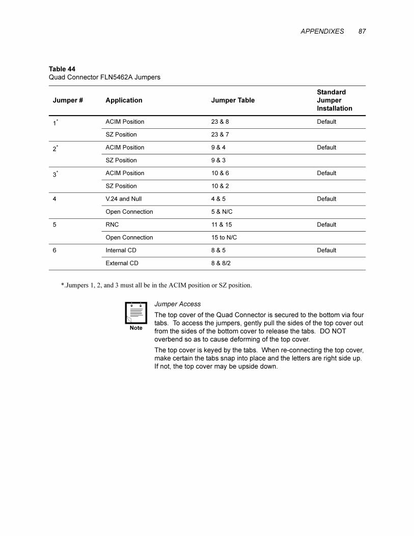
APPENDIXES 87
.
Table 44
Quad Connector FLN5462A Jumpers
Jumper # Application Jumper Table
Standard
Jumper
Installation
1* ACIM Position 23 & 8 Default
SZ Position 23 & 7
2* ACIM Position 9 & 4 Default
SZ Position 9 & 3
3* ACIM Position 10 & 6 Default
SZ Position 10 & 2
4 V.24 and Null 4 & 5 Default
Open Connection 5 & N/C
5 RNC 11 & 15 Default
Open Connection 15 to N/C
6 Internal CD 8 & 5 Default
External CD 8 & 8/2
*.Jumpers 1, 2, and 3 must all be in the ACIM position or SZ position.
Jumper Access
The top cover of the Quad Connector is secured to the bottom via four
tabs. To access the jumpers, gently pull the sides of the top cover out
from the sides of the bottom cover to release the tabs. DO NOT
overbend so as to cause deforming of the top cover.
The top cover is keyed by the tabs. When re-connecting the top cover,
make certain the tabs snap into place and the letters are right side up.
If not, the top cover may be upside down.
Note

88 ASTRO DIU, Owner’s Manual
Figure 17
DIU3000 Communication Adaptor Cable FKN4632A (W cable)

APPENDIXES 89
Appendix B: Communcation Cables.
.
Figure 18
DIU3000-to-Base Station Modem Eliminator Cable (options C542AC and
C542AD)
Figure 19
DIU3000 to Channel Bank DSU Cable (options C543AC and C543AD)

90 ASTRO DIU, Owner’s Manual
Appendix C: Glossary of Terms and Phrases
Access Code A preprogrammed network access code transferred on the radio channel,
that allows private communication between end users. The access code may
be PL, DPL, Single Tone, DTMF, MDC1200 or ASTRO N word.
ASTRO™ MOTOROLA Trademark for Land Mobile Radio Sector's FDMA digital
radio system.
Bit A binary digit.
Bit Rate In a bit stream, the number of bits occurring per unit of time, usually
expressed as bits per second or "bps".
Channel Rate The data rate at which information is transmitted through the channel.
Embedded Signalling Digital signalling information transmitted simultaneously with the voice.
Frequency Division Multiple
Access (FDMA)
An access method of improving spectrum efficiency that divides the
communication channel into two or more individual channels.
Improved Multi–Band
Excitation* (IMBE) coding
One of the analog–to–digital voice conversion methods used by the
DIU3000.
Inbound Base station to console direction of data/voice transfer.
Infrastructure A fixed radio network that allows indirect communication between field
radios and centralized dispatches and control points. The infrastructure also
expands the coverage area of otherwise directly communicating field
radios.
Logical ID (LID) A key variable used to encrypt a message.
Multikey The ASTRO devices capability to be equipped with multiple encryption
keys.
Multiple Algorithm The ASTRO devices capability to be equipped with two hardware–based
encryption algorithms. This feature supports interoperability and migration.
Outbound Console to base station direction of data/voice transfer.
SECURENET Motorola's 12 kbps voice encryption system.
SmartZone™ A trunking system using multiple sites with a variable number of repeaters
to cover large geographic areas.
Stat–Alert™ A signalling scheme based on the MDC standard.
Zeroization (of encryption
keys)
The process of erasing encryption keys.
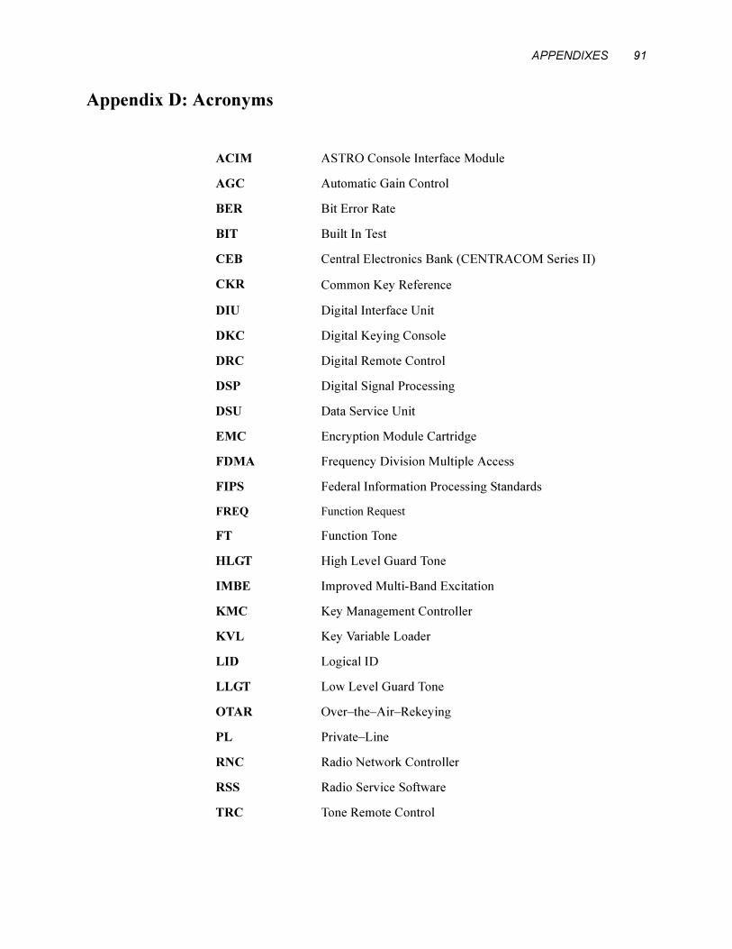
APPENDIXES 91
Appendix D: Acronyms
ACIM ASTRO Console Interface Module
AGC Automatic Gain Control
BER Bit Error Rate
BIT Built In Test
CEB Central Electronics Bank (CENTRACOM Series II)
CKR Common Key Reference
DIU Digital Interface Unit
DKC Digital Keying Console
DRC Digital Remote Control
DSP Digital Signal Processing
DSU Data Service Unit
EMC Encryption Module Cartridge
FDMA Frequency Division Multiple Access
FIPS Federal Information Processing Standards
FREQ Function Request
FT Function Tone
HLGT High Level Guard Tone
IMBE Improved Multi-Band Excitation
KMC Key Management Controller
KVL Key Variable Loader
LID Logical ID
LLGT Low Level Guard Tone
OTAR Over–the–Air–Rekeying
PL Private–Line
RNC Radio Network Controller
RSS Radio Service Software
TRC Tone Remote Control