Embed Size (px)
Citation preview
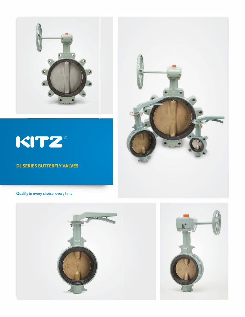
DJ SERIES BUTTERFLY VALVES
Quality in every choice, every time.


® BFV-1
CODE NUMBER SYSTEM
Page
ILLUSTRATED INDEX . . . . . . . . . . . . . . . . . . . . . . . . . . . . . . . .BFV-2
ENGINEERING DATA INDEX . . . . . . . . . . . . . . . . . . . . . . . . . . .BFV-15
D J S E R I E S B U T T E R F LY VA LV E SGENERAL INDEX
®A PRODUCT OF TECHNOLOGY
1
6 1 2 3 E L 200
{ { { { { { {
2 3 4 5 6 7
NOTES:
(1) 2” - 8”(2) 2” - 12”(3) 10” - 24” Standard (2” - 8” Optional)(4) Standard for 14” - 24”
1 SERIES STYLE CODE WAFER 5 LUG 6
5 LINER CODE NBR (BUNA-N) B EPDM E
2 BODY CODE DUCTILE IRON 1
3 DISC/STEM CODE DUCTILE IRON + ENP / 410 SS 1 ALUMINUM BRONZE / 410 SS 2 316 SS / 329 SS 3
7 SIZE CODE 2” 200 2 1/2” 212 3” 300 4” 400 5” 500 6” 600 8” 800 10” 910 12” 912 14” 914 16” 916 18” 918 20” 920 24” 924
4 PRESSURE CODE 150 PSI (4) 1 250 PSI (2) 3
6 OPERATOR CODE LEVER (1) L GEAR (3) G BARE STEM X

®BFV-2
150 PSI
Code # 5111(B/E)GCode # 5121(B/E)GCode # 5131(B/E)G
150 PSI
Code # 6111(B/E)GCode # 6121(B/E)GCode # 6131(B/E)G
250 PSI
Code # 5113(B/E)GCode # 5123(B/E)GCode # 5133(B/E)G
250 PSI
Code # 6113(B/E)GCode # 6123(B/E)GCode # 6133(B/E)G
250 PSI
Code # 5113(B/E)(L/G)Code # 5123(B/E)(L/G)Code # 5133(B/E)(L/G)
WAFER
LUG
WAFER
LUG
WAFER
LUG
10” - 12”
Ductile Iron Body - Extended Neck
DISC: DI - AB - 316SSLINER: NBR - EPDM
14” - 24”
Ductile Iron Body - Extended Neck
DISC: DI - AB - 316SSLINER: NBR - EPDM
2” - 8”
Ductile Iron Body - Extended Neck
DISC: DI - AB - 316SSLINER: NBR - EPDM
250 PSI
Code # 6113(B/E)(L/G)Code # 6123(B/E)(L/G)Code # 6133(B/E)(L/G)
DJ SERIES BUTTERFLY VALVES
ILLUSTRATED INDEX
NUMERICALINDEXCODE # PAGE2” - 8”5113................BFV-5, 75123................BFV-5, 75133................BFV-5, 76113................BFV-4, 66123................BFV-4, 66133................BFV-4, 6
10” - 12”5113...................BFV-95123...................BFV-95133...................BFV-96113...................BFV-86123...................BFV-86133...................BFV-8
14” - 24”5111.................BFV-135121.................BFV-135131.................BFV-136111.................BFV-126121.................BFV-126131.................BFV-12
DJ
SE
RIE
S B
UT
TE
RF
LY
VA
LV
ES
- I
LL
US
TR
AT
ED
IN
DE
X

® BFV-3
DJ SERIES BUTTERFLY VALVES
SIZE 2” - 12”
DJ S
ER
IES
BU
TT
ER
FL
Y V
AL
VE
S - 250 P
SI Zinc die-cast plug with
electroplated zinc coating
Lug Style
DISC:Ductile Iron +ENPAluminum Bronze316 Stainless steel
O-RING (2):NBR (BUNA-N)EPDM
SEAT:NBR (BUNA-N)EPDM
Stainless Steel Stem
Polyacetal Stem Bearing
Stem Bearing G/F PTFE

®BFV-4
DIMENSIONS
Wafer LugSIZE d D C H H1 H2 L D1 Lbs Lbs
Kgs Kgsin. 2 1.97 3.54 4.75 7.52 5.79 2.64 1.69 7.09 4.2 6.6mm 50 50 90 120.5 191 147 67 43 180 1.9 3.0in 2 1/2 2.56 4.09 5.50 7.83 6.10 2.95 1.81 7.09 5.1 7.9mm 65 65 104 139.5 199 155 75 46 180 2.3 3.6in 3 3.15 4.88 6.00 8.54 6.81 3.58 1.81 7.09 6.8 11.0mm 80 80 124 152.5 217 173 91 46 180 3.1 5.1in 4 3.94 5.75 7.50 8.94 7.20 3.98 2.06 7.09 7.7 18.0mm 100 100 146 190.5 227 183 101 52 180 3.5 8.1in 5 4.92 6.93 8.50 10.43 8.31 5.00 2.19 9.06 13.0 25.0mm 125 125 176 216 265 211 127 56 230 5.8 11.0in 6 5.91 8.11 9.50 10.91 8.78 5.47 2.19 9.06 18.0 30.0mm 150 150 206 241.5 277 223 139 56 230 8.0 14.0in 8 7.76 10.12 11.75 11.61 9.76 6.65 2.38 13.78 28.0 48.0mm 200 197 257 298.5 295 248 169 60 350 13.0 22.0
MATERIAL LIST
NO. NAME OF PART SPECIFICATION
1 BODY DUCTILE IRON (A536 Gr. 65-45-12)
3 STEM* (1) STAINLESS STEEL (A276, Type 410;
AISI, Type 329)
4 DISC DUCTILE IRON, AL. BRONZE, AND 316 SS
9 LEVER (LOCKING) ALUMINUM DIE-CAST
10 HANDLE BOLT CARBON STEEL
16A/B NAME PLATE ALUMINUM
45A O-RING NBR/EPDM
45B O-RING NBR/EPDM
67A BEARING POLYACETAL
67B/C STEM BEARING G/F PTFE, METAL BACKED PTFE (6", 8")
85 PLUG ZINC DIE-CAST (2)
90 CAP P.V.C. (2"-6")
98 INDEX PLATE CARBON STEEL
99A SET BOLT CARBON STEEL
99B NUT CARBON STEEL
103 BOTTOM STEM STAINLESS STEEL (A276, TYPE 410;
AISI, Type 329)
106 SEAT RUBBER (3) NBR/EPDM
145 SPRING WASHER CARBON STEEL
STOP LEVER (8”) DUCTILE IRON (A536 Gr. 65-45-12)
(1) Line scribed on top of the stem indicates the disc position
(2) Chromate Coating
(3) Vulcanized to the Body
NOTE:KITZ lug style butterfly valves are rated for bi-directional dead end service to full working pressure of the valve with the downstream flange removed. In dead end ser-vice exceeding 96 hours, a downstream flange is recommended.
Code # 6113 (B/E) LDisc: Ductile Iron(A536 + ENP)
Code # 6123 (B/E) LDisc: Aluminum Bronze*(C95400)
Code # 6133 (B/E) LDisc: 316 SS*(A351 Gr. CF8M)
BUTTERFLY VALVES - 250 PSI*NSF372 • Lug Design • Ductile Iron Body • Extended Neck
Bi-Directional • Molded Seat • ISO Mounting Pad • Locking LeverSIZE 2” - 8”
STANDARDS: MSS SP-67 & API-609 Cat. A END CONNECTION: ANSI CL 125/150 FLANGES WALL THICKNESS: KITZ STD
DJ
SE
RIE
S B
UT
TE
RF
LY
VA
LV
ES
- 2
50 P
SI
- L
EV
ER
OP
ER
AT
OR

® BFV-5
DIMENSIONS
Wafer LugSIZE d D C H H1 H2 L D1 Lbs Lbs
Kgs Kgsin. 2 1.97 3.54 4.75 7.52 5.79 2.64 1.69 7.09 4.2 6.6mm 50 50 90 120.5 191 147 67 43 180 1.9 3.0in 2 1/2 2.56 4.09 5.50 7.83 6.10 2.95 1.81 7.09 5.1 7.9mm 65 65 104 139.5 199 155 75 46 180 2.3 3.6in 3 3.15 4.88 6.00 8.54 6.81 3.58 1.81 7.09 6.8 11.0mm 80 80 124 152.5 217 173 91 46 180 3.1 5.1in 4 3.94 5.75 7.50 8.94 7.20 3.98 2.06 7.09 7.7 18.0mm 100 100 146 190.5 227 183 101 52 180 3.5 8.1in 5 4.92 6.93 8.50 10.43 8.31 5.00 2.19 9.06 13.0 25.0mm 125 125 176 216 265 211 127 56 230 5.8 11.0in 6 5.91 8.11 9.50 10.91 8.78 5.47 2.19 9.06 18.0 30.0mm 150 150 206 241.5 277 223 139 56 230 8.0 14.0in 8 7.76 10.12 11.75 11.61 9.76 6.65 2.38 13.78 28.0 48.0mm 200 197 257 298.5 295 248 169 60 350 13.0 22.0
MATERIAL LIST
NO. NAME OF PART SPECIFICATION
1 BODY DUCTILE IRON (A536 Gr. 65-45-12)
3 STEM* (1) STAINLESS STEEL (A276, Type 410;
AISI, Type 329)
4 DISC DUCTILE IRON, AL. BRONZE, AND 316 SS
9 LEVER (LOCKING) ALUMINUM DIE-CAST
10 HANDLE BOLT CARBON STEEL
16A/B NAME PLATE ALUMINUM
45A O-RING NBR/EPDM
45B O-RING NBR/EPDM
67A BEARING POLYACETAL
67B/C STEM BEARING G/F PTFE, METAL BACKED PTFE (6", 8")
85 PLUG ZINC DIE-CAST (2)
90 CAP P.V.C. (2"-6")
98 INDEX PLATE CARBON STEEL
99A SET BOLT CARBON STEEL
99B NUT CARBON STEEL
103 BOTTOM STEM STAINLESS STEEL (A276, TYPE 410;
AISI, Type 329)
106 SEAT RUBBER (3) NBR/EPDM
145 SPRING WASHER CARBON STEEL
STOP LEVER (8”) DUCTILE IRON (A536 Gr. 65-45-12)
(1) Line scribed on top of the stem indicates the disc position
(2) Chromate Coating
(3) Vulcanized to the Body
Code # 5113 (B/E) LDisc: Ductile Iron(A536 + ENP)
Code # 5123 (B/E) LDisc: Aluminum Bronze*(C95400)
Code # 5133 (B/E) LDisc: 316 SS*(A351 Gr. CF8M)
BUTTERFLY VALVES - 250 PSI*NSF372 • Wafer Design • Ductile Iron Body • Extended Neck
Bi-Directional • Molded Seat • ISO Mounting Pad • Locking LeverSIZE 2” - 8”
STANDARDS: MSS SP-67 & API-609 Cat. A END CONNECTION: ANSI CL 125/150 FLANGES WALL THICKNESS: KITZ STD
DJ S
ER
IES
BU
TT
ER
FL
Y V
AL
VE
S - 250 P
SI - L
EV
ER
OP
ER
AT
OR

®BFV-6
DIMENSIONS
Wafer LugSIZE d D C H H1 H2 L D1 L1 Lbs Lbs
Kgs Kgsin. 2 1.97 3.54 4.75 7.64 5.79 2.64 1.69 3.15 4.78 4.9 7.1mm 50 50 90 120.5 194 147 67 42.9 80 121.5 2.2 3.2in. 2 1/2 2.56 4.09 5.50 7.95 6.10 2.95 1.81 3.15 4.78 5.7 8.4mm 65 65 104 139.5 202 155 75 46 80 121.5 2.6 3.8in 3 3.15 4.88 6.00 9.29 6.81 3.58 1.81 4.33 5.31 8.6 13.0mm 80 80 124 152.5 236 173 91 46 110 135 3.9 5.8in 4 3.94 5.75 7.50 9.69 7.20 3.98 2.06 4.33 5.31 9.2 19.0mm 100 100 146 190.5 246 183 101 52.3 110 135 4.2 8.8in 5 4.92 6.93 8.50 10.79 8.31 5.00 2.19 4.33 5.91 14.0 26.0mm 125 125 176 216 274 211 127 55.6 110 150 6.3 12.0in 6 5.91 8.11 9.50 11.26 8.78 5.47 2.19 4.33 5.91 19.0 32.0mm 150 150 206 241.5 286 223 139 55.6 110 150 8.5 15.0in 8 7.76 10.12 11.75 12.80 9.76 6.65 2.38 6.69 7.09 30.0 49.0mm 200 197 257 298.5 325 248 169 60.5 170 180 13.0 22.0
MATERIAL LIST
NO. NAME OF PART SPECIFICATION
1 BODY DUCTILE IRON (A536 Gr. 65-45-12)
3 STEM* STAINLESS STEEL (A276, Type 410;
AISI, Type 329)
4 DISC (1) DUCTILE IRON, AL. BRONZE, AND 316 SS
16A/B NAME PLATE ALUMINUM
45A/B O-RING NBR/EPDM
67A BEARING POLYACETAL
67B/C STEM BEARING G/F PTFE (2” - 5”)
METAL BACKED PTFE (6”, 8”)
85 PLUG ZINC DIE-CAST (2)
99A SET BOLTS CARBON STEEL
102 GEAR UNIT ALUMINUM DIE-CAST (B85, SC102A)
103 BOTTOM STEM STAINLESS STEEL (A276, TYPE 410;
AISI, Type 329)
106 SEAT RUBBER (3) NBR/EPDM
145 SPRING WASHER CARBON STEEL
(1) Line scribed on top of the stem indicates the disc position
(2) Chromate Coating
(3) Vulcanized to the Body
Code # 6113 (B/E) GDisc: Ductile Iron(A536 + ENP)
Code # 6123 (B/E) GDisc: Aluminum Bronze*(C95400)
Code # 6133 (B/E) GDisc: 316 SS*(A351 Gr. CF8M)
BUTTERFLY VALVES - 250 PSI*NSF372 • Lug Design • Ductile Iron Body • Extended Neck
Bi-Directional • Molded Seat • ISO Mounting Pad • Gear OperatorSIZE 2” - 8”
STANDARDS: MSS SP-67 & API-609 Cat. A END CONNECTION: ANSI CL 125/150 FLANGES WALL THICKNESS: KITZ STD
DJ
SE
RIE
S B
UT
TE
RF
LY
VA
LV
ES
- 2
50 P
SI
- G
EA
R O
PE
RA
TO
R
NOTE:KITZ lug style butterfly valves are rated for bi-directional dead end service to full working pressure of the valve with the downstream flange removed. In dead end ser-vice exceeding 96 hours, a downstream flange is recommended.
For gear operator details, refer to page 24.

® BFV-7
DIMENSIONS
Wafer LugSIZE d D C H H1 H2 L D1 L1 Lbs Lbs
Kgs Kgsin. 2 1.97 3.54 4.75 7.64 5.79 2.64 1.69 3.15 4.78 4.9 7.1mm 50 50 90 120.5 194 147 67 42.9 80 121.5 2.2 3.2in. 2 1/2 2.56 4.09 5.50 7.95 6.10 2.95 1.81 3.15 4.78 5.7 8.4mm 65 65 104 139.5 202 155 75 46 80 121.5 2.6 3.8in 3 3.15 4.88 6.00 9.29 6.81 3.58 1.81 4.33 5.31 8.6 13.0mm 80 80 124 152.5 236 173 91 46 110 135 3.9 5.8in 4 3.94 5.75 7.50 9.69 7.20 3.98 2.06 4.33 5.31 9.2 19.0mm 100 100 146 190.5 246 183 101 52.3 110 135 4.2 8.8in 5 4.92 6.93 8.50 10.79 8.31 5.00 2.19 4.33 5.91 14.0 26.0mm 125 125 176 216 274 211 127 55.6 110 150 6.3 12.0in 6 5.91 8.11 9.50 11.26 8.78 5.47 2.19 4.33 5.91 19.0 32.0mm 150 150 206 241.5 286 223 139 55.6 110 150 8.5 15.0in 8 7.76 10.12 11.75 12.80 9.76 6.65 2.38 6.69 7.09 30.0 49.0mm 200 197 257 298.5 325 248 169 60.5 170 180 13.0 22.0
MATERIAL LIST
NO. NAME OF PART SPECIFICATION
1 BODY DUCTILE IRON (A536 Gr. 65-45-12)
3 STEM* STAINLESS STEEL (A276, Type 410;
AISI, Type 329)
4 DISC (1) DUCTILE IRON, AL. BRONZE, AND 316 SS
16A/B NAME PLATE ALUMINUM
45A/B O-RING NBR/EPDM
67A BEARING POLYACETAL
67B/C STEM BEARING G/F PTFE (2” - 5”)
METAL BACKED PTFE (6”, 8”)
85 PLUG ZINC DIE-CAST (2)
99A SET BOLTS CARBON STEEL
102 GEAR UNIT ALUMINUM DIE-CAST (B85, SC102A)
103 BOTTOM STEM STAINLESS STEEL (A276, TYPE 410;
AISI, Type 329)
106 SEAT RUBBER (3) NBR/EPDM
145 SPRING WASHER CARBON STEEL
(1) Line scribed on top of the stem indicates the disc position
(2) Chromate Coating
(3) Vulcanized to the Body
Code # 5113 (B/E) GDisc: Ductile Iron(A536 + ENP)
Code # 5123 (B/E) GDisc: Aluminum Bronze*(C95400)
Code # 5133 (B/E) GDisc: 316 SS*(A351 Gr. CF8M)
BUTTERFLY VALVES - 250 PSI*NSF372 • Wafer Design • Ductile Iron Body • Extended Neck
Bi-Directional • Molded Seat • ISO Mounting Pad • Gear OperatorSIZE 2” - 8”
STANDARDS: MSS SP-67 & API-609 Cat. A END CONNECTION: ANSI CL 125/150 FLANGES WALL THICKNESS: KITZ STD
DJ S
ER
IES
BU
TT
ER
FL
Y V
AL
VE
S - 250 P
SI - G
EA
R O
PE
RA
TO
R
For gear operator details, refer to page 24.

®BFV-8
DIMENSIONS
Wafer LugSIZE d D C H H1 H2 L D1 L1 Lbs Lbs
Kgs Kgsin. 10 9.72 12.28 14.25 15 11.97 8.62 2.69 9.84 9.84 59.5 81mm 250 247 312 362 381 304 219 68.3 250 250 27.0 37.0 in. 12 11.65 14.33 17.00 15.98 12.95 9.61 3.06 9.84 9.84 77.2 106.6mm 300 296 364 432 406 329 244 77.7 250 250 35.0 48.0
MATERIAL LIST
NO. NAME OF PART SPECIFICATION
1 BODY DUCTILE IRON (A536 Gr. 65-45-12)
3 STEM STAINLESS STEEL (A276, Type 410;
AISI, Type 329)
4 DISC DUCTILE IRON, AL. BRONZE, AND 316 SS
16A/B NAME PLATE ALUMINUM
35 END PLATE BOLTS CARBON STEEL
36 GLAND PLATE BOLTS STAINLESS STEEL
45A/B O-RING NBR/EPDM
60 KEY (12”) CARBON STEEL
67A/B/C STEM BEARING METAL BACKED PTFE
99 SET BOLTS CARBON STEEL
102 GEAR UNIT
103 BOTTOM STEM STAINLESS STEEL (A276, TYPE 410;
AISI, Type 329)
106 SEAT RUBBER (2) NBR/EPDM
144 GLAND PLATE CARBON STEEL
145A/B SPRING WASHER CARBON STEEL
147 END PLATE CARBON STEEL
(1) Line scribed on top of the stem indicates the disc position
(2) Vulcanized to the Body
Code # 6113 (B/E) GDisc: Ductile Iron(A536 + ENP)
Code # 6123 (B/E) GDisc: Aluminum Bronze*(C95400)
Code # 6133 (B/E) GDisc: 316 SS*(A351 Gr. CF8M)
BUTTERFLY VALVES - 250 PSI*NSF372 • Lug Design • Ductile Iron Body • Extended Neck
Bi-Directional • Molded Seat • ISO Mounting Pad • Gear OperatorSIZE 10” - 12”
STANDARDS: MSS SP-67 & API-609 Cat. A END CONNECTION: ANSI CL 125/150 FLANGES WALL THICKNESS: KITZ STD
DJ
SE
RIE
S B
UT
TE
RF
LY
VA
LV
ES
- 2
50 P
SI
- G
EA
R O
PE
RA
TO
R
For gear operator details, refer to page 24.
NOTE:KITZ lug style butterfly valves are rated for bi-directional dead end service to full working pressure of the valve with the downstream flange removed. In dead end ser-vice exceeding 96 hours, a downstream flange is recommended.

® BFV-9
DIMENSIONS
Wafer LugSIZE d D C H H1 H2 L D1 L1 Lbs Lbs
Kgs Kgsin. 10 9.72 12.28 14.25 15 11.97 8.62 2.69 9.84 9.84 59.5 81mm 250 247 312 362 381 304 219 68.3 250 250 27.0 37.0 in. 12 11.65 14.33 17.00 15.98 12.95 9.61 3.06 9.84 9.84 77.2 106.6mm 300 296 364 432 406 329 244 77.7 250 250 35.0 48.0
MATERIAL LIST
NO. NAME OF PART SPECIFICATION
1 BODY DUCTILE IRON (A536 Gr. 65-45-12)
3 STEM STAINLESS STEEL (A276, Type 410;
AISI, Type 329)
4 DISC DUCTILE IRON, AL. BRONZE, AND 316 SS
16A/B NAME PLATE ALUMINUM
35 END PLATE BOLTS CARBON STEEL
36 GLAND PLATE BOLTS STAINLESS STEEL
45A/B O-RING NBR/EPDM
60 KEY (12”) CARBON STEEL
67A/B/C STEM BEARING METAL BACKED PTFE
99 SET BOLTS CARBON STEEL
102 GEAR UNIT
103 BOTTOM STEM STAINLESS STEEL (A276, TYPE 410;
AISI, Type 329)
106 SEAT RUBBER (2) NBR/EPDM
144 GLAND PLATE CARBON STEEL
145A/B SPRING WASHER CARBON STEEL
147 END PLATE CARBON STEEL
(1) Line scribed on top of the stem indicates the disc position
(2) Vulcanized to the Body
Code # 5113 (B/E) GDisc: Ductile Iron(A536 + ENP)
Code # 5123 (B/E) GDisc: Aluminum Bronze(C95400)
Code # 5133 (B/E) GDisc: 316 SS(A351 Gr. CF8M)
BUTTERFLY VALVES - 250 PSI*NSF372 • Wafer Design • Ductile Iron Body • Extended Neck
Bi-Directional • Molded Seat • ISO Mounting Pad • Gear OperatorSIZE 10” - 12”
STANDARDS: MSS SP-67 & API-609 Cat. A END CONNECTION: ANSI CL 125/150 FLANGES WALL THICKNESS: KITZ STD
DJ S
ER
IES
BU
TT
ER
FL
Y V
AL
VE
S - 250 P
SI - G
EA
R O
PE
RA
TO
R
For gear operator details, refer to page 24.
® BFV-10
Intentionally Left Blank

® BFV-11
DJ SERIES BUTTERFLY VALVES
150 PSISIZE 14” - 24”
DJ S
ER
IES
BU
TT
ER
FL
Y V
AL
VE
S - 150 P
SISeal Washer
Support Bolt
Lug Style
DISC:Ductile Iron +ENPAluminum Bronze316 Stainless steel
O-RING:NBR (BUNA-N)EPDM
SEAT:NBR (BUNA-N)EPDM
Stainless Steel Stem
Stem Bearing G/F PTFE
Stem Bearing G/F PTFE
®BFV-12
DIMENSIONS
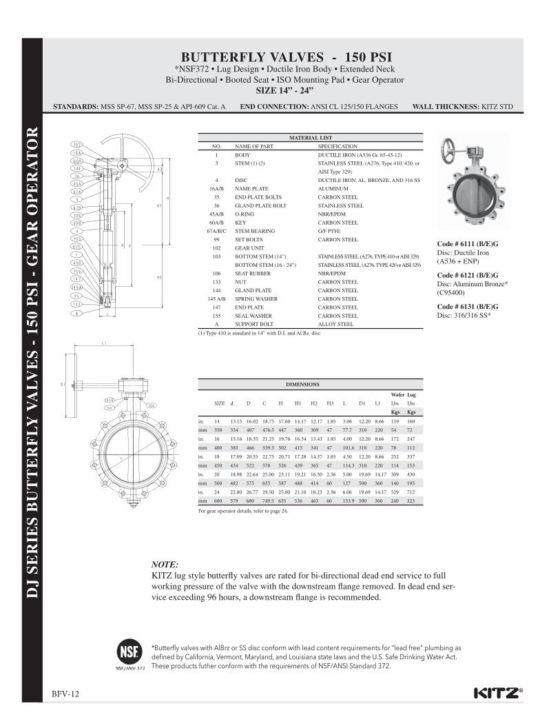
Wafer LugSIZE d D C H H1 H2 H3 L D1 L1 Lbs Lbs
Kgs Kgsin. 14 13.15 16.02 18.75 17.60 14.17 12.17 1.85 3.06 12.20 8.66 119 160mm 350 334 407 476.5 447 360 309 47 77.7 310 220 54 72in. 16 15.16 18.35 21.25 19.76 16.34 13.43 1.85 4.00 12.20 8.66 172 247mm 400 385 466 539.5 502 415 341 47 101.6 310 220 78 112in. 18 17.09 20.55 22.75 20.71 17.28 14.37 1.85 4.50 12.20 8.66 252 337mm 450 434 522 578 526 439 365 47 114.3 310 220 114 153in. 20 18.98 22.64 25.00 23.11 19.21 16.30 2.36 5.00 19.69 14.17 309 430mm 500 482 575 635 587 488 414 60 127 500 360 140 195in. 24 22.80 26.77 29.50 25.00 21.10 18.23 2.36 6.06 19.69 14.17 529 712mm 600 579 680 749.5 635 536 463 60 153.9 500 360 240 323
MATERIAL LIST
NO. NAME OF PART SPECIFICATION
1 BODY DUCTILE IRON (A536 Gr. 65-45-12)
3 STEM (1) (2) STAINLESS STEEL (A276, Type 410, 420, or
AISI Type 329)
4 DISC DUCTILE IRON, AL. BRONZE, AND 316 SS
16A/B NAME PLATE ALUMINUM
35 END PLATE BOLTS CARBON STEEL
36 GLAND PLATE BOLT STAINLESS STEEL
45A/B O-RING NBR/EPDM
60A/B KEY CARBON STEEL
67A/B/C STEM BEARING G/F PTFE
99 SET BOLTS CARBON STEEL
102 GEAR UNIT
103 BOTTOM STEM (14”) STAINLESS STEEL (A276, TYPE 410 or AISI 329)
BOTTOM STEM (16 - 24”) STAINLESS STEEL (A276, TYPE 420 or AISI 329)
106 SEAT RUBBER NBR/EPDM
133 NUT CARBON STEEL
144 GLAND PLATE CARBON STEEL
145 A/B SPRING WASHER CARBON STEEL
147 END PLATE CARBON STEEL
155 SEAL WASHER CARBON STEEL
A SUPPORT BOLT ALLOY STEEL
(1) Type 410 is standard in 14” with D.I. and Al.Bz. disc
Code # 6111 (B/E)GDisc: Ductile Iron(A536 + ENP)
Code # 6121 (B/E)GDisc: Aluminum Bronze*(C95400)
Code # 6131 (B/E)GDisc: 316/316 SS*
BUTTERFLY VALVES - 150 PSI*NSF372 • Lug Design • Ductile Iron Body • Extended Neck
Bi-Directional • Booted Seat • ISO Mounting Pad • Gear OperatorSIZE 14” - 24”
STANDARDS: MSS SP-67, MSS SP-25 & API-609 Cat. A END CONNECTION: ANSI CL 125/150 FLANGES WALL THICKNESS: KITZ STD
DJ
SE
RIE
S B
UT
TE
RF
LY
VA
LV
ES
- 1
50 P
SI
- G
EA
R O
PE
RA
TO
R
For gear operator details, refer to page 24.
NOTE:KITZ lug style butterfly valves are rated for bi-directional dead end service to full working pressure of the valve with the downstream flange removed. In dead end ser-vice exceeding 96 hours, a downstream flange is recommended.

® BFV-13
DIMENSIONS
Wafer LugSIZE d D C H H1 H2 H3 L D1 L1 Lbs Lbs
Kgs Kgsin. 14 13.15 16.02 18.75 17.60 14.17 12.17 1.85 3.06 12.20 8.66 119 160mm 350 334 407 476.5 447 360 309 47 77.7 310 220 54 72in. 16 15.16 18.35 21.25 19.76 16.34 13.43 1.85 4.00 12.20 8.66 172 247mm 400 385 466 539.5 502 415 341 47 101.6 310 220 78 112in. 18 17.09 20.55 22.75 20.71 17.28 14.37 1.85 4.50 12.20 8.66 252 337mm 450 434 522 578 526 439 365 47 114.3 310 220 114 153in. 20 18.98 22.64 25.00 23.11 19.21 16.30 2.36 5.00 19.69 14.17 309 430mm 500 482 575 635 587 488 414 60 127 500 360 140 195in. 24 22.80 26.77 29.50 25.00 21.10 18.23 2.36 6.06 19.69 14.17 529 712mm 600 579 680 749.5 635 536 463 60 153.9 500 360 240 323
MATERIAL LIST
NO. NAME OF PART SPECIFICATION
1 BODY DUCTILE IRON (A536 Gr. 65-45-12)
3 STEM (1) (2) STAINLESS STEEL (A276, Type 410, 420, or
AISI Type 329)
4 DISC DUCTILE IRON, AL. BRONZE, AND 316 SS
16A/B NAME PLATE ALUMINUM
35 END PLATE BOLTS CARBON STEEL
36 GLAND PLATE BOLT STAINLESS STEEL
45A/B O-RING NBR/EPDM
60A/B KEY CARBON STEEL
67A/B/C STEM BEARING G/F PTFE
99 SET BOLTS CARBON STEEL
102 GEAR UNIT
103 BOTTOM STEM (14”) STAINLESS STEEL (A276, TYPE 410 or AISI 329)
BOTTOM STEM (16 - 24”) STAINLESS STEEL (A276, TYPE 420 or AISI 329)
106 SEAT RUBBER NBR/EPDM
133 NUT CARBON STEEL
144 GLAND PLATE CARBON STEEL
145 A/B SPRING WASHER CARBON STEEL
147 END PLATE CARBON STEEL
155 SEAL WASHER CARBON STEEL
A SUPPORT BOLT ALLOY STEEL
(1) Type 410 is standard in 14” with D.I. and Al.Bz. disc
Code # 5111 (B/E)GDisc: Ductile Iron(A536 + ENP)
Code # 5121 (B/E)GDisc: Aluminum Bronze*(C95400)
Code # 5131 (B/E)GDisc: 316/316 SS*
BUTTERFLY VALVES - 150 PSI*NSF372 • Wafer Design • Ductile Iron Body • Extended Neck
Bi-Directional • Booted Seat • ISO Mounting Pad • Gear OperatorSIZE 14” - 24”
STANDARDS: MSS SP-67, MSS SP-25 & API-609 Cat. A END CONNECTION: ANSI CL 125/150 FLANGES WALL THICKNESS: KITZ STD
DJ S
ER
IES
BU
TT
ER
FL
Y V
AL
VE
S - 150 P
SI - G
EA
R O
PE
RA
TO
R
For gear operator details, refer to page 24.

®BFV-14
Intentionally Left Blank

®BFV-15
PAGE NO.
ENGINEERING DATA INDEX
®A PRODUCT OF TECHNOLOGY
Specifications . . . . . . . . . . . . . . . . . . . . . . . . . . . . . . . . . BFV-16
Properties of Valve Material . . . . . . . . . . . . . . . . . . . . . BFV-17
Resilient Liner Materials . . . . . . . . . . . . . . . . . . . . . . . . BFV-18
Chemical Resistance Chart . . . . . . . . . . . . . . . . . . . . . . BFV-19
Flow Data - Cv . . . . . . . . . . . . . . . . . . . . . . . . . . . . . . . BFV-20
Ductile Series Butterfly - Exploded View . . . . . . . . . . . BFV-21
Flange Bolt Data . . . . . . . . . . . . . . . . . . . . . . . . . . . . . . BFV-22
Locking Lever Data . . . . . . . . . . . . . . . . . . . . . . . . . . . . BFV-23
Gear Operator Data . . . . . . . . . . . . . . . . . . . . . . . . . . . . BFV-24
Bare Stem Dimensional Datafor Actuation . . . . . . . . . . . . . . . . . . . . . . . . . . . . . . . . . BFV-25
Torque Data . . . . . . . . . . . . . . . . . . . . . . . . . . . . . . . . . . BFV-26
Cross Reference Chart . . . . . . . . . . . . . . . . . . . . . . . . . . BFV-27
Storage/Handling and Installation Guide . . . . . . . . . . . . BFV-28-29

®BFV-16
SPECIFICATIONS
KITZ Butterfly valves are designed and manufactured to provide maximum performance on recommendedservice applications at the lowest possible Initial and Life Cycle cost. They meet or exceed the followingstandards developed through research, laboratory tests and years of experience.
BUTTERFLY VALVES
• API-609 Category A Design
• MSS SP-25 MarkingMSS SP-67 Design & Testing
SAMPLE BUTTERFLY VALVE SPECIFICATION
Valves shall have Ductile Iron Body with 2” Extended Neck to allow for insulation. Bodydesign shall be Full Lug or Wafer style having a bi-directional differential pressure rating of250 psi (2” - 12”) and 150 psi (14” - 24”). Stem shall be of Stainless Steel with top and bottombushing of dissimilar materials with positive stem retention mechanism. Valve shall have(Aluminum Bronze) Disc and booted seat of (EPDM) rubber. Lug style valve shall be capable of providing bi-directional “Dead End Service” at full rated pressure with the down stream flange removed. Sizes 2” - 6” shall be Lever Operated with 10 position throttling plate and Sizes 8” and larger shall be Gear Operated and manufactured in accordance to MSS SP-67, MSS SP-25 and API-609.
KITZ Code Numbers:
5123EL - Wafer (2” - 6”) Lever Operated
6123EL - Lug (2” - 6”) Lever Operated
5123EG - Wafer (8” - 12”) Gear Operated
6123EG - Lug (8” - 12”) Gear Operated
5121EG - Wafer (14” - 24”) Gear Operated
6121EG - Lug (14” - 24”) Gear Operated
SP
EC
IFIC
AT
ION
S

® BFV-17
PR
OP
ER
TIE
S O
F V
AL
VE
MA
TE
RIA
LS
PROPERTIES OF VALVE MATERIALS
AST
M (
UN
S)A
lloy
Phy
sica
l Pro
pert
ies
(min
.)
Cu
SnP
bZ
nB
iC
Ni
SP
CR
Mn
Mo
SiF
eA
lO
ther
Tens
ile(k
si)
Yie
ld(k
si)
Elo
ng.
(%)
CO
PP
ER
AL
LO
WS
B16
(C
3600
0)
Free
Cut
ting
Bra
ss
60.0
-63.
0 ...
2.5-
3.7
bal
......
......
......
......
...0.
35
......
* *
*
B61
(C
9220
0)
Nav
y "M
" (S
team
B
ronz
e)
86.0
-90.
0 5.
5-6.
5 1.
0-2.
0 3.
0-5.
0...
...1.
00...
......
......
......
......
......
...
B62
(C
8360
0)
Com
posi
tion
Bro
nze
84.0
-86.
0 4.
0-6.
0 4.
0-6.
0 4.
0-6.
0 1.
00...
......
......
......
......
30
14
20
A14
8 (C
9540
0)
Alu
min
um B
ronz
e 85
.0
......
......
......
......
......
......
4.0
11.0
......
......
B28
3 (C
3770
0)Fo
rged
Bra
ss58
.0-6
1.0
...1.
5-2.
5ba
l...
......
......
......
......
0.30
......
5018
25
Nav
al B
rass
59.0
-62.
00.
50-1
.00.
20ba
l0.
1052
2225
B58
4 (C
8440
0)
Lea
ded
Sem
i-R
ed B
rass
81
.0
3.0
7.0
9.0
......
......
......
......
......
......
......
...
B76
3 (C
8953
0)
Cas
t Bi-
Se A
lloy
84.0
-89.
0 3.
5-6.
0 0.
20
7.0-
9.0
1.0-
2.0
...1.
00
...0.
05
......
...0.
01
0.30
0.
01
.10-
.30
......
...
B96
7 (B
4930
0)
Cu-
Zn-
Sn-B
i Allo
y 58
.0-6
2.0
1.3-
1.8
0.01
ba
l 0.
50-2
.0
...1.
50
...0.
20
...0.
03
...0.
10
0.10
0.
50
0.80
......
...
IRO
N
A12
6 C
lass
B
Cas
t Ger
y Ir
on
...
...
...
...
...
...
...
0.15
0.
75
...
...
...
...
bal
...
...
31...
...
A53
6†
Duc
tile
Iron
(65
-45-
12)
...
...
...
...
...
3.5-
3.8
...
0.01
.0
2-.0
5 ...
.15-
.40
...
2.3-
2.8
bal
...
0.05
65
45
12
A39
5 D
uctil
e Ir
on (
Ferr
itic)
...
...
...
...
...
3.
00 m
in
...
...
0.08
...
...
...
2.
50
bal
...
...
60
40
18
A43
9 Ty
pe D
2D
uctil
e N
i-R
esis
t ...
...
...
...
...
3.
00
18.0
-22.
0 ...
0.
08
2.75
-4.0
0.
7-1.
25
...
1.5-
3.0
bal
...
...
58
30
7
STA
INL
ESS
ST
EE
L
......
......
......
......
......
......
......
......
......
...
A35
1, G
R C
F830
4 (C
ast)
J92
600
...
...
...
...
...0.
08
8.0-
11.0
0.
04
0.04
18
.0-2
1.0
1.50
0.
50
2.00
...
...
...
70
30
35
A35
1, G
R C
F8M
31
6 (C
ast)
J92
900
...
...
...
...
...
0.08
9.
0-12
.0
0.04
0.
04
18.0
-21.
0 1.
50
2.0-
3.0
1.50
...
...
...
70
30
30
A27
6, T
ype
304
304
(Wro
ught
) S3
0400
...
...
...
...
...
0.
08
8.0-
11.0
0.
03
0.05
18
.0-2
0.0
2.00
...
1.
00
...
...
...
75
30
40
A27
6, T
ype
316
316
(Wro
ught
) S3
1600
...
...
...
...
...
0.
08
10.0
-14.
0 0.
03
0.05
16
.0-1
8.0
2.00
2.
0-3.
0 1.
00
...
...
...
75
30
40
AIS
I Ty
pe 3
29
329
(Wro
ught
) S3
2900
...
...
...
...
...
0.
08
3.0-
6.0
0.03
0.
04
23.0
-28.
0 1.
50
1.0-
3.0
1.00
...
...
...
10
5 80
25
A27
6, T
ype
410
410
(Wro
ught
) S4
1000
...
...
...
...
...
0.
08-0
.015
...
0.
03
0.04
11
.0-1
3.0
1.00
...
1.
00
...
...
0.05
-0.3
0Cb
......
...
CA
RB
ON
ST
EE
L
A10
5 Fo
rged
Car
bon
Stee
l ...
...
...
...
...
0.
04...
0.0
5 0.
04
...
0.60
-1.0
5 ...
0.
35
...
...
...
70
36
22
A21
6, G
r. W
CB
C
ast C
arbo
n St
eel J
0300
2...
...
...
...
...
0.
30
...
0.05
0.
04
...
1.00
...
0.
60
...
...
1.0
max
70
36
22
BO
LTIN
G
A30
7, G
r. B
C
arbo
n St
eel B
olt &
Stu
d ...
...
...
...
...
0.
29...
0.05
0.
04
...
0.90
...
...
...
...
...
60
...
18
A19
3 G
r. B
7 B
-7
Allo
y St
ud
...
...
...
...
...
0.37
-0.4
9 ...
0.
04
0.04
0.
75-1
.20
0.65
-1.1
0 0.
15-
0.25
0.
15-
0.35
...
...
...
12
5 10
5 16
A19
3 G
r. B
8 C
l.2
304
SS S
tud
...
...
...
...
...
0.08
8.
0-11
.0
0.03
0.
45
16.0
-20.
0 2.
00
...
1.00
...
...
...
12
5 10
0 12
* Su
bjec
ttoT
empe
r, Si
ze a
nd F
orm
† C
hem
ical
req
uire
men
ts a
re n
ot s
peci
fied
unde
r th
is s
peci
ficat
ion,
com
posi
tion
is s
ubor
inat
e to
the
mec
hani
cal p
rope
rtie
s sp
ecifi
ed u
nder
A53
6.

®BFV-18
RESILIENT LINER MATERIALS
EPDM
EPDM is a terpolymer elastomer made from ethylene-propylene diene monomer. EPDM has good abrasionand tear resistance and offers excellent chemical resistance to a variety of acids and alkalines. It is susceptibleto attack by oil and is not recommended for applications involving petroleum oils, strong acids, or strongalkalines. It should not be used for compressed air lines. It has exceptionally good weather aging and ozoneresistance and has fairly good resistance to ketones and alcohols.
BUNA-N (Nitrile) (NBR)
Buna-N is a general-purpose oil resistant polymer known as Nitrile rubber. It is a copolymer of butadiene andacrylonitrile. It has good resistance to Hydraulic fluid, oil, water, and solvents. It shows good tensile strengthand abrasion resistance while displaying good compression set. It is not recommended for highly polar solventssuch as acetone and methyl ethyl ketone nor in chlorinated hydrocarbons, ozone or nitro hydrocarbons.
LINER MATERIAL TEMPERATURE RANGE
LINER MATERIAL TEMPERATURE Continuous IntermittentEPDM -29 ~ 107°C / -20 ~ 225°F -29 ~ 121°C / -20 ~ 250°FBUNA-N (Nitrile) -12 ~ 82°C / 10 ~ 180°F ---
KITZ utilizes proprietary compound formulas for each elastomer. They provide the right combinationof seat compression, abrasion and chemical resistance to match a broad range of applications.
Note: Elastomeric seat materials are not suitable for steam service.
RE
SIL
IEN
T L
INE
R M
AT
ER
IAL
S

® BFV-19
CHEMICAL RESISTANCE GUIDE
MATERIALS/FLUID DISC SEAT
AL-BRZ DUCTILE 316 NBR EPDM
Acetic Acid (10%) Very Poor Poor Excellent Very Poor Good
Air Excellent Excellent Excellent Excellent Excellent
Ammonia (anhydrous liquid) Very Poor Good Excellent Poor Good
Ammonia (solution) Very Poor Good Excellent Good Good
Ammonium Sulfate Very Poor Poor Good Excellent Excellent
Animal Oil Good Excellent Excellent Excellent Good
Calcium Carbonate Very Poor Very Poor Good Excellent Excellent
Carbonic Acid -- Very Poor Good Good Good
Chlorinated Water Very Poor -- Poor Good -
Ethane - Good Good Excellent Very Poor
Ethyl Alcohol Good Good Excellent Good Excellent
Freon12 Excellent Good Excellent Good Excellent
Gasoline (refined/unleaded) Good Good Excellent Poor Very Poor
Hydrochloric Acid Very Poor Very Poor Very Poor Poor Good
Hydrogen Gas (cold) Excellent Good Excellent Good Good
Lubricating Oil (petroleum base) Good Excellent Excellent Excellent Very Poor
Methyl Alcohol Excellent Good Excellent Good Excellent
Mineral Oil Good Good Excellent Excellent Very Poor
Natural Gas Excellent Excellent Excellent Good Very Poor
Oxygen (cold) Excellent Good Excellent Good Good
Petroleum Oil (refined) Good - - Good Very Poor
Propane Gas - Good Excellent Excellent Very Poor
Sea Water Excellent Very Poor Good Excellent Excellent
Soybean Oil - Poor Excellent Excellent Poor
Sulfuric Acid (7%) Very Poor Very Poor Good Good Good
Sulfuric Acid (20%) Very Poor Very Poor Very Poor Very Poor Good
Sulfuric Acid (50% & larger) Very Poor Very Poor Very Poor Very Poor Good
Sulfurous Acid Very Poor Very Poor Good Poor Poor
Steam (100ºC) Excellent Excellent Excellent Very Poor Good
Vegetable Oil Good Poor Excellent Excellent Poor
Water (hot, 150ºF) Excellent Poor Excellent Very Poor Good
The above performance data has been developed from field testing, customer field reports and/or in-house testing. Properties/applications shown are typical. Your specific application should not be undertaken without independent study and evaluation for suitability. While the utmost care has been used in compiling this data, we assume no responsibility for errors.
CH
EM
ICA
L R
ES
IST
AN
CE
GU
IDE

®BFV-20
FL
OW
DA
TA
- C
v V
AL
UE
S
0
10
20
30
40
50
60
70
80
90
100
10° 20° 30°4 0° 50°6 0° 70°8 0° 90°
Valve Opening (º)
Flow
Rat
e (%
)
SIZE % OPEN
Inch mm 10º 20º 30º 40º 50º 60º 70º 80º 90º
2 50 0 5 10 18 29 47 75 107 124
2 1/2 65 0 12 22 39 64 102 163 232 270
3 80 0 17 33 57 94 149 240 341 397
4 100 0 29 55 96 158 252 404 577 671
5 125 0 44 83 145 369 381 610 871 1013
6 150 0 66 126 219 362 576 922 1318 1532
8 200 0 125 230 400 660 1050 1680 2400 2792
10 250 0 160 325 575 950 1514 2423 3462 4024
12 300 0 258 493 859 1418 2260 3618 5168 6010
14 350 0 324 617 1076 1776 2829 4530 6472 7525
16 400 0 433 826 1441 2378 3760 6068 8669 10080
18 450 0 564 1076 1876 3096 4933 7898 11283 13120
20 500 0 588 1311 2286 3774 6012 9626 13751 15990
24 600 0 1018 1942 3388 5590 8907 14688 22742 23690
* Cv is defined as the flow in GPM that a valve will carry with a pressure drop of 1.0 psi, whenthe media is 60ºF water.
FLOW DATACv Values for DJ Series Butterfly Valves
LIQUID FLOW:
Q = Cv P/S Q = liquid flow rate (gallons per minute)
P = pressure drop across valve (psi) S = specific gravity of media
Cv is defined as the flow in GPM that a valvewill carry with a pressure drop of 1.0 psi whenthe media is water at 60º.
VALVE SIZING:- On/Off ServiceSimply select a valve which is the same as the piping system.
- Throttling ServiceSelect Cv data from above table: 30 - 60ºand follow these steps:
1) Define: (Q) - System flow requirements (DP) - Maximum allowable pressure drop (S) - Specific gravity of the pipeline media2) Calculate Cv using above formula3) Select valve size between (30 - 60º)4) Do not exceed maximum velocity: Liquids: 20 ft. / second Gases: 15,000 ft. /minute V = S x .321 (liquid only) A A = Area of pipe in square inches
Example: Throttling ServiceGiven:
Q - 975 GPM (Flow)DP - 1.50 (Pressure Drop)S = (Specific Gravity)
1) Cv = Q = 975
2) From Cv table: 8” Valve Cv Flow Rate Open range 30 - 60º: 230 - 1050
3) Velocity - V -
= 6.22 ft/sec.
6.22 ft./sec. is within the limits. So for givenconditions, an 8” valve should be used.
GAS FLOW:
Q = 1360 Cv P x P1/ST
Q = gas flow rate (SCFH — std. cu. ft./hr.)S = specific gravity of gas (air = 1.0)T = temp. - degrees rankin (ºF + 460)DP = pressure drop across valve (psi)P1 = upstream pressure (psia) absolute
Note that DP must be less than .5( Flow is critical when DP is greater than .5 P1 ).
S x .321A
975 x .32150.3
SP
1.501.0
Flow Characteristics (Static Clean Water) Flow Rate Cv* Values

® BFV-21
DJ SERIES BUTTERFLY VALVESEXPLODED VIEW
Gea
r U
nit
Gea
r U
nit
Gea
r U
nit
Gla
nd P
late
Gla
nd P
late
O-R
ing
O-R
ing
O-R
ing
Bea
ring
Stem
Stem
Stem
Stem
Bea
ring
Stem
Bea
ring
Stem
Bea
ring
Stem
Bea
ring
Stem
Bea
ring
Spri
ng W
ashe
r
Spri
ng W
ashe
r
Spri
ng W
ashe
r
Seat
Rub
ber
Seat
Rub
ber
Seat
Rub
ber
Dis
cD
isc
Dis
c
2” -
8”
10”
- 12
”14
” -
24”
End
Pla
teE
nd P
late
Set B
olt
Set B
olt
Set B
olt
Bod
yB
ody
Bod
y
Stem
Bea
ring
Bot
tom
Ste
mB
otto
m S
tem
Bot
tom
Ste
m
Plug
O-R
ing
O-R
ing
EX
PL
OD
ED
VIE
WS
- DJ S
ER
IES
BU
TT
ER
FL
Y V
AL
VE
S

®BFV-22
FLANGE BOLT DATA
Size Diameter
NumberBolt Length
“A”Hex Head Bolt
Length “B”Stud Length
“C”Bolt/studHex Head
Bolt
inch mm inch mm inch inch inch mm inch mm inch mm
2 50 5/8-11 15.875 4 8 4 1/4 107.95 1 1/2 38.1 5 127.00
2 1/2 65 5/8-11 15.875 4 8 4 3/4 120.65 1 5/8 41.275 5 1/2 139.70
3 80 5/8-11 15.875 4 8 4 3/4 120.65 1 3/4 44.45 5 1/2 139.70
4 100 5/8-11 15.875 8 16 5 127.00 1 7/8 47.625 5 3/4 146.05
5 125 3/4-10 19.05 8 16 5 1/4 133.35 1 7/8 47.625 6 1/4 158.75
6 150 3/4-10 19.05 8 16 5 1/2 139.70 2 50.8 6 1/2 165.10
8 200 3/4-10 19.05 8 16 5 3/4 146.05 2 1/8 53.975 6 3/4 171.45
10 250 7/8-9 22.225 12 24 6 1/2 165.10 2 3/8 60.325 7 1/2 190.50
12 300 7/8-9 22.225 12 24 7 177.80 2 5/8 66.675 8 203.20
14 350 1-8 25.4 12 24 7 1/2 190.50 2 3/4 69.85 8 3/4 222.25
16 400 1-8 25.4 16 32 8 1/2 215.90 3 1/4 82.55 9 3/4 247.65
18 450 1 1/8-7 28.575 16 32 9 1/4 234.95 3 5/8 92.075 10 3/4 273.05
20 500 1 1/8-7 28.575 20 40 10 1/4 260.35 4 101.6 11 1/2 292.10
24 600 1 1/4-7 31.75 20 40 11 3/4 298.45 4 5/8 117.475 13 1/4 336.55
Note: Use pipe flanges conforming to ANSI Class 125 or 150. Steel, Cast Iron, Bronze and Plastic may be used. The use of additional flange gaskets are not required.
Threads on bolts, studs and nuts shall be in accordance with the Unified Course Thread Series (UNC), Class A&B (ANSI B-1.1).
FL
AN
GE
BO
LT
DA
TA
WAFER STYLE LUG STYLE LUG/WAFER STYLE
Bolt Hex Head Bolt Stud

® BFV-23
LOCKING LEVER DATA5000 & 6000 DUCTILE SERIES
DIMENSIONS - SPECIFICATIONS
SIZE A B C Wt. In. 2 7.09 1.73 4.45 Lbs. 0.4 mm 50 180 44 113 kgs. 0.2 in. 2 1/2 7.09 1.73 4.45 Lbs. 0.4 mm 65 180 44 113 kgs. 0.2 in. 3 7.09 1.73 4.45 Lbs. 0.4 mm 80 180 44 113 kgs. 0.2 in. 4 7.09 1.73 4.45 Lbs. 0.4 mm 100 180 44 113 kgs. 0.2 in. 5 9.06 2.13 4.45 Lbs. 0.9 mm 125 230 54 113 kgs. 0.4 in. 6 9.06 2.13 4.45 Lbs. 0.9 mm 150 230 54 113 kgs. 0.4 in. 8 13.78 1.54 5.67 Lbs. 2.9 mm 200 350 39 144 kgs. 1.3
MATERIAL LIST
NO. NAME OF PART MATERIAL SPECIFICATION
9 HANDLE ALUMINUM DIE-CAST B85, SC102A
HANDLE (2”) DUCTILE IRON A536 Gr. 65-4.5-12
10 HANDLE BOLT ALLOY STEEL (not shown)
CARBON STEEL (8” Only) 1307 Gr. B
16C HANDLE WASHER CARBON STEEL (8” Only)(not shown) A36
117 HANDLE SPRING STAINLESS STEEL A276 Type 304
124 SPRING PIN STAINLESS STEEL A276 Type 304
157 STOP LEVER ALUMINUM DIE-CAST B85 SC102A
DUCTILE IRON (8” Only) A538 Gr. 65-4.5-12
90 CAP P.V.C. (2” - 6”)
98 INDEX PLATE - -
99A SET BOLT - -
99B NUT - -
145 SPRING WASHER - -
LO
CK
ING
LE
VE
R D
AT
A

®BFV-24
GEAR OPERATOR5000 & 6000 DUCTILE SERIES
MATERIAL LIST
NAME OF PART MATERIAL
Gear Operator 2” - 12”
Gear Case Aluminum Die-Cast
Handle Aluminum Die-Cast
Handle Shaft Stainless Steel
MATERIAL LIST
NAME OF PART MATERIAL
Gear Operator 14” - 24”
Gear Case Cast Iron
Handle Carbon Steel
Handle Shaft Stainless Steel
DIMENSIONS - 2” - 12”
SIZE H3 D1 L1 E F Gear No. Wt.in. 2 0.73 3.15 4.78 1.14 1.10 No. 0 Lbs. 1.1mm 50 18.5 80 121.5 29 28 kgs. .05in. 21/2 0.73 3.15 4.78 1.14 1.10 No. 0 Lbs. 1.1mm 65 18.5 80 121.5 29 28 kgs. .05in. 3 0.94 4.33 5.31 1.44 1.59 No. 1a Lbs. 2.2mm 80 24 110 135 36.5 40.5 kgs. 1.0in. 4 0.94 4.33 5.31 1.44 1.59 No. 1a Lbs. 2.2mm 100 24 110 135 36.5 40.5 kgs. 1.0in. 5 0.94 4.33 5.91 1.44 1.59 No. 1b Lbs. 2.2mm 125 24 110 150 36.5 40.5 kgs. 1.0in. 6 0.94 4.33 5.91 1.44 1.59 No. 1b Lbs. 2.2mm 150 24 110 150 36.5 40.5 kgs. 1.0in. 8 1.26 6.69 7.09 2.01 2.48 No. 2a Lbs. 6.6mm 200 32 170 180 51 63 kgs. 3.0in. 10 1.26 9.84 9.84 2.01 2.48 No. 2b Lbs. 6.6mm 250 32 250 250 51 63 kgs. 3.0in. 12 1.26 9.84 9.84 2.01 2.48 No. 2c Lbs. 6.6mm 300 32 250 250 51 63 kgs. 3.0in. 14 1.85 12.20 8.66 2.13 2.58 No. 3 Lbs. 20.0mm 350 47 310 220 54 65.5 kgs. 9.0in. 16 1.85 12.20 8.66 2.13 2.58 No. 3 Lbs. 20.0mm 400 47 310 220 54 65.5 kgs. 9.0in. 18 1.85 12.20 8.66 2.13 2.58 No. 3 Lbs. 20mm 450 47 310 220 54 65.5 kgs. 9.0in. 20 2.36 19.69 14.17 2.68 3.48 No. 4 Lbs. 53.0mm 500 60 500 360 68 88.5 kgs. 24.0in. 24 2.36 19.69 14.17 2.68 3.48 No. 4 Lbs. 53.0mm 600 60 500 360 68 88.5 kgs. 24.0
The Ductile Series butterfly valves can be operatedwith a heavy-duty operator with indicator. The gearoperator is recommended for valves 8” and larger fortrouble-free operation in all moisture and weatherconditions. The gear operator is a self-locking wormgear type with adjustable stops for open/close position.
Ordering: Specify by adding (G) to the Code Number, i.e. 6123EG.
GE
AR
OP
ER
AT
OR

® BFV-25
BARE STEM DIMENSIONALDATA FOR ACTUATION
DIMENSIONS - SPECIFICATIONS
SIZE S D H H1 H2 AxB C No. h M FLANGE TYPE
in. 2 .35 .47 5.79 .55 .33 1.97x1.97 1.97 4 .28 M6 F5mm 50 9 12 147 14 8.5 50x50 50 4 7 M6 F5in. 21/2 .35 .47 6.10 .55 .33 1.97x1.97 1.97 4 .28 M6 F5mm 65 9 12 155 14 8.5 50x50 50 4 7 M6 F5in. 3 .43 .55 6.81 .55 .33 2.76x2.76 2.76 4 .39 M6 F7mm 80 11 14 173 14 8.5 70x70 70 4 10 M6 F7in. 4 .43 .55 7.20 .55 .33 2.76x2.76 2.76 4 .39 M6 F7mm 100 11 14 183 14 8.5 70x70 70 4 10 M6 F7in. 5 .51 .63 8.31 .87 .33 2.76x2.76 2.76 4 .39 M6 F7mm 125 13 16 211 22 8.5 70x70 70 4 10 M6 F7in. 6 .51 .63 8.78 .87 .33 2.76x2.76 2.76 4 .39 M6 F7mm 150 13 16 223 22 8.5 70x70 70 4 10 M6 F7in. 8 .61 .83 9.76 .94 .39 3.86x3.86 4.02 4 .43 M6 F10mm 200 15.5 21 248 24 10 98x98 102 4 11 M6 F10in. 10 .94 1.14 11.97 1.26 .39 3.86x3.86 4.02 4 .43 M10 F10mm 250 24 29 304 32 10 98x98 102 4 11 M10 F10in. 12 1.06 1.28 12.95 1.26 .39 3.86x3.86 4.02 4 .43 M10 F10mm 300 27 32.5 329 32 10 98x98 102 4 11 M10 F10
DIMENSIONS - 14” - 24”
SIZE D E F H H1 H2 H3 AxB C No. h FLANGE TYPE
in. 14 1.50 .39 1.61 14.17 2.56 .98 2.56 5.51x5.28 5.51 4 .71 F14mm 350 38 10 41 360 65 25 65 140x134 140 4 18 F14in. 16 1.50 .39 1.61 16.34 2.56 .98 2.56 5.51x5.28 5.51 4 .71 F14mm 400 38 10 41 415 65 25 65 140x134 140 4 18 F14in. 18 1.50 .39 1.61 17.28 2.56 .98 2.56 5.51x5.28 5.51 4 .71 F14mm 450 38 10 41 439 65 25 65 140x134 140 4 18 F14in. 20 1.97 .55 2.11 19.21 3.70 1.10 3.15 6.69x6.38 6.50 4 .87 F16mm 500 50 14 53.5 488 94 28 80 170x162 165 4 22 F16in. 24 1.97 .55 2.11 21.10 3.70 1.10 3.15 6.69x6.38 6.50 4 .87 F16mm 600 50 14 53.5 536 94 28 80 170x162 165 4 22 F16
Up to 8” 10” & 12” 14” - 24”
BA
RE
ST
EM
DIM
EN
SIO
NA
L D
AT
A F
OR
AC
TU
AT
ION

®BFV-26
TORQUE INFORMATION / DATA
5000 & 6000 SERIES / TORQUE VALUES
TO
RQ
UE
IN
FO
RM
AT
ION
/ D
AT
A
TORQUE
Torque is the rotary effort required to operate avalve.There are three factors that determine the valvestorque:
1) Disc / Seat Interference Friction 2) Bearing Friction 3) Dynamic torque
BREAKING TORQUE
Breaking torque is a combination of the abovementioned frictions at any given differential pressure. This value is normally the highest required torque for “wet” (water and other non-lubricating medias at ambient temperature) on/off service.
• The listed torque is for NBR (BUNA-N) and EPDM.• For “dry” service (non-lubricating, dry gas media), multiply highest value by 1.6.• For “lubed” service (clean, non-abrasive lubricating media) multiply highest value by .85.• When sizing actuators for single valve appli-cations, multiply highest value by 1.25.
SIZE 50 PSI 100 PSI 150 PSI 200 PSI 250 PSI2 90 97 100 103 105
2 1/2 135 146 148 154 1563 216 233 238 246 2504 270 291 296 308 3125 496 534 544 565 5726 690 743 759 781 7978 1,169 1,259 1,286 1,328 1,34910 2,347 2,528 2,582 2,673 2,70812 3,544 3,817 3,898 4,036 4,08914 3,331 3,470 3,608 - -16 5,395 5,620 5,844 - -18 6,458 6,727 6,996 - -20 9,576 9,975 10,374 - -24 15,498 16,144 16,789 - -

® BFV-27
CR
OS
S R
EF
ER
EN
CE
CH
AR
T
CROSS REFERENCE CHARTS
G
STYLE KITZ CENTERLINE CRANE DEMCO GRINNELL JENKINS MILWAUKEE NIBCO
E
R
DUCTILE IRON
* This cross reference chart is provided for the convenience of our customers. Valves listed may not be identical in design or materials of construction.

®BFV-28

® BFV-29

®BFV-30
NOTES

® BFV-31
NOTES

®BFV-32
ACCEPTANCEAll quotations are for acceptance within 30 days from date of quota-tion unless extended in writing. In the event a purchase order is placed after this time, the Seller’s company reserves the right to requote prices of all valves offered. All orders and contracts are subject to credit ap-proval and acceptance by KITZ.
FREIGHTAll materials will be shipped F.O.B.point of shipment – no freight allowance unless otherwise stated and agreed upon with the Buyer.
PRICESThere will be added to all prices quoted any sales, excise, or similar tax which Seller may be required to collect on or in connection with the sale. Seller reserves the right to can-cel any order in the event that selling prices shall be established by Feder-al, State or other governmental reg-ulation with respect to the products covered by the order which shall be lower than the prices specified in the order.
ESCALATION TERMSPrices shown in this price schedule re-flect the costs in effect at the time of pub-lication. These prices will remain firm on all products with a quoted delivery of twenty six (26) weeks or less. On prod-ucts with a quoted delivery of more than 26 weeks, the Seller has a right to price and invoice at the applicable price sheet in effect at the time of shipment. In no event will the invoiced price be less than price originally quoted.
that the product is properly installed and is used in the service for which Seller recommends it and that writ-ten claim, specifying the alleged de-fect, is presented to the Seller within one year from the date of shipment. For Copper Alloy and Iron valves sold and installed in the U.S. the warranty is five years. Seller shall in no event be responsible for claims of A) labor, expenses, or other damag-es occasioned by defective parts or products or for B) consequential or secondary damages. The Warranty stated in this paragraph is in lieu of all other warranties, either ex-pressed or implied. With respect to warranties, this paragraph states Buyer’s exclusive remedy and Seller’s exclusive liability.
DESIGNBecause of a policy of continuous product improvement, Seller re-serves the right to change design, materials or specifications without notice. There will be a charge for modifying an order after it has been entered when such change or modifi-cation results in additional engineer-ing or clerical work for either KITZ or its suppliers.
NOTEKITZ reserves the right to correct any obvious clerical errors in quo-tations, invoices and other contracts.
DEFERRED SHIPMENTSIf for any reason the Buyer desires to delay shipments more than 30 days after manufacturing or to place a hold or to stop the order during the manufacturing cycle, the Seller’s company reserves the right to con-sider the order cancelled and to in-voke cancellation charges.
CREDIT TERMSAs quoted. Overdue balances will be subject to 1.5% service charge per month on such indebtedness.
DELIVERIESShipments made to the Buyer shall at all times be subject to the approv-al of Seller’s Credit Department. All schedules of shipments are estimated as closely as possible and Seller will use its best effort to ship within the time schedule but does not guarantee to do so. Seller shall not be liable for any direct, indirect, or consequential damage or loss caused by delay in delivery, regardless of the cause of delay. Items offered from stock are subject to prior sale.
RETURNSNo returns are allowed without prior arrangements made with the Seller. Product considered for return must be in new, resalable condition and of current design.
WARRANTYSeller will replace without charge or refund the purchase price of prod-ucts manufactured by Seller which prove to be defective in material or workmanship, provided in each case
GENERAL TERMS AND CONDITIONS

® BFV-33
®A PRODUCT OF TECHNOLOGY
PRODUCT CATALOGSKITZ has a wide selection of products available.
Please call Customer Service at 800-772-0073 for additional catalog requests.

KITZ Corporation of America, Inc.