Embed Size (px)
Citation preview
DL4 Installation & Operation Instructions
09 July 2009 DL4_M01 Issue 1C Page 1 of 29
DL4 4-CHANNEL DIGITAL LOGGER
INSTALLATION & OPERATION INSTRUCTIONS
Author: John Moyce
Number of Pages: 29
SHM Communications Ltd., Valley House, Winnall Valley Road, Winchester, Hampshire SO23 0LD
Tel 01962 865142 Fax 01962 862451
Copyright SHM Communications Ltd. 2009_OUT_SHM.DOT

DL4 Installation & Operation Instructions
09 July 2009 DL4_M01 Issue 1C Page 2 of 29
AMENDMENT RECORD
Date Issue Amended By Comment
26/08/98 1A J.J.Moyce Original
21/01/01 1B J.J.Moyce Minor corrections
09/07/09 1C J.J.Moyce Added WEEE information
DL4 Installation & Operation Instructions
09 July 2009 DL4_M01 Issue 1C Page 3 of 29
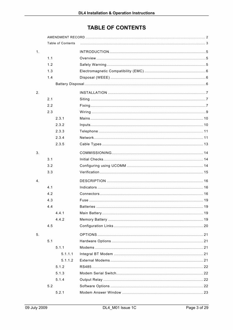
TABLE OF CONTENTSAMENDMENT RECORD ................................................................................................................. 2
Table of Contents ...................................................................................................................... 3
1. INTRODUCTION.................................................................................. 5
1.1 Overview ............................................................................................. 5
1.2 Safety Warning .................................................................................... 5
1.3 Electromagnetic Compatibility (EMC) .................................................... 6
1.4 Disposal (WEEE) ................................................................................. 6
Battery Disposal ....................................................................................................... 6
2. INSTALLATION ................................................................................... 7
2.1 Siting .................................................................................................. 7
2.2 Fixing .................................................................................................. 7
2.3 Wiring ................................................................................................. 9
2.3.1 Mains ................................................................................................ 10
2.3.2 Inputs................................................................................................ 10
2.3.3 Telephone ......................................................................................... 11
2.3.4 Network............................................................................................. 11
2.3.5 Cable Types ...................................................................................... 13
3. COMMISSIONING.............................................................................. 14
3.1 Initial Checks..................................................................................... 14
3.2 Configuring using UCOMM ................................................................. 14
3.3 Verification ........................................................................................ 15
4. DESCRIPTION .................................................................................. 16
4.1 Indicators .......................................................................................... 16
4.2 Connectors ........................................................................................ 16
4.3 Fuse ................................................................................................. 19
4.4 Batteries ........................................................................................... 19
4.4.1 Main Battery ...................................................................................... 19
4.4.2 Memory Battery ................................................................................. 19
4.5 Configuration Links ............................................................................ 20
5. OPTIONS .......................................................................................... 21
5.1 Hardware Options .............................................................................. 21
5.1.1 Modems ............................................................................................ 21
5.1.1.1 Integral BT Modem ............................................................................ 21
5.1.1.2 External Modems ............................................................................... 21
5.1.2 RS485............................................................................................... 22
5.1.3 Modem Serial Switch.......................................................................... 22
5.1.4 Output Relay ..................................................................................... 22
5.2 Software Options ............................................................................... 22
5.2.1 Modem Answer Window ..................................................................... 23

DL4 Installation & Operation Instructions
09 July 2009 DL4_M01 Issue 1C Page 4 of 29
5.2.2 Dial In ............................................................................................... 23
5.2.3 Alarms .............................................................................................. 23
5.2.3.1 Non-Latched Alarms .......................................................................... 24
5.2.3.2 Latched Alarms.................................................................................. 25
6. MAINTENANCE ................................................................................. 26
6.1 Removing the Sub-Chassis................................................................. 26
6.2 Battery Life........................................................................................ 26
6.3 Battery Replacement .......................................................................... 26
7. TECHNICAL SPECIFICATION ............................................................ 27
DL4 Installation & Operation Instructions
09 July 2009 DL4_M01 Issue 1C Page 5 of 29
1. INTRODUCTION
This document describes the installation, commissioning, operation and maintenance ofthe DL4 4-channel logger. All hardware aspects are covered in detail but the softwareaspects of commissioning and operation are only covered as an overview.
1.1 Overview
The DL4 logger provides secure reliable logging of digital inputs. The normal use of thelogger is to count pulses generated by volt-free contact closures and store the numberof pulses recorded over a configurable time interval (typically every 30 minutes).Alternatively the logger can monitor the state of an input and store the time and date ofany changes of state (on-to-off or off-to-on).
The logger is mains powered but the logged data is kept in non-volatile (batterysupported) storage so that logged readings are maintained while the mains power is off.The logger can be supplied with a UPS (Un-interruptible Power Supply) that allows datato be logged for several days without mains power.
The logger can provide security of data with 4 levels of passwords, but for applicationsthat do not require this, the logger can be programmed to operate without passwords.
The logger is fully configurable in terms of channel type, logging interval, channel sizeand security, and can also be configured to generate channel alarms.
The logger has a number of communications options, including an integral telephonemodem and an RS485 network. The RS485 network allows a number of inter-linkedloggers to be interrogated from a central point or via a single modem connection. TheDL4 logger is fully compatible with other SHM loggers (eg. the UL8 Universal 8-channellogger) and these loggers can be networked in any combination.
All SHM loggers communicate using the same efficient reliable real-time protocol.
There are a number of software applications that can communicate with SHM loggers :-
• Stark RT (Windows). This is a full-function real time energy monitoring andreporting suite that will collect data automatically from SHM loggers and providecomprehensive analysis of the data.
• UREAD (DOS). This is a utility that can collect data locally from an SHM loggerand store the data in a file for subsequent import into Stark RT. It is designedfor use if the communications link to a logger is temporarily unavailable.
• UCSV (DOS). This utility collects data from an SHM logger and stores it as aComma-Separated-Value (CSV) file that can be imported into database andspreadsheet programs (eg. Microsoft Excel).
• UCOMM (DOS). This utility is required to commission and configure an SHMlogger. If SHM carry out the commissioning of the logger on site, the user maynot need this utility, unless there is a requirement to alter the configurationsubsequently.
1.2 Safety Warning
The installation of the Logger requires connection to hazardous voltages, and shouldonly be undertaken by suitably qualified personnel. The main circuit board has exposedvoltages at mains live potential.
DL4 Installation & Operation Instructions
09 July 2009 DL4_M01 Issue 1C Page 6 of 29
The equipment should be connected to the supply earth at terminal E of terminal blockTB1.
Always ensure that the equipment is installed with the above earthing arrangements inplace.
1.3 Electromagnetic Compatibility (EMC)
To comply with EMC regulations, the DL4 should be installed with regard to minimizinginterference to any sensitive equipment nearby.
The use of screened cables ensures minimal RF interference and also reduces thesusceptibility of the system to external interference.
When using screened cable, the screen should be earthed at the logger end on thespade connector provided (PL7), and with as short a tail as possible. The length of theun-screened conductors as they emerge from the screen to the terminal block shouldalso be kept as short as possible.
In certain circumstances, un-screened cables (eg. multi-pair ‘telephone’ type cable)may work satisfactorily. In these cases the cable runs should be short, and should notrun alongside high-current power supply cabling. However, if in doubt, screenedcabling should be used.
1.4 Disposal (WEEE)
In the European Union, this symbol indicates that this product is not to bedisposed of with household waste, according to the WEEE Directive(2002/96/EC). This product should be deposited at an appropriate facilityto enable recovery and recycling. For more information about disposal ofwaste electronic equipment, contact your local waste authority, approved
WEEE scheme or household waste disposal service.
1.4.1 Battery Disposal
Caution. Do not dispose of the batteries in a fire or with household waste.Contact your local waste disposal agency for the address of the nearest
battery disposal site.

DL4 Installation & Operation Instructions
09 July 2009 DL4_M01 Issue 1C Page 7 of 29
2. INSTALLATION
2.1 Siting
The logger should be sited with regard to the length of cabling required, the proximity toa telephone socket (if required) and the availability of a mains supply.
The logger will typically be interfaced to the pulse outputs of up to 4 meters, but quitelong cable runs from logger to meter are permissible. Hence proximity to the metersneed not be an issue, particularly if a site is already wired with a multi-pair cablenetwork.
The optional integral modem is supplied with a 3 metre cable. If possible the loggershould be sited within 2m of a BT telephone socket.
If the logger is to communicate directly with a PC (rather than via a modem) then thelogger should ideally be sited less than 15m from the PC. In situations where this is notpossible, an RS485 link (this is an option that must be ordered) can be used, allowingPC to logger distances of up to 1500m.
The logger should also be reasonably close to a mains supply, either a switched fusedspur (preferable) or a 13A socket.
In addition, the minimum clearances specified in Figure [1] should be observed,otherwise access to the cable-entry glands and local interrogation socket will bedifficult.
2.2 Fixing
Release the 4 screws at the corners of the polycarbonate lid of the DL4 and remove thelid.
The logger base plate is fixed to the wall by four screws, one at each corner.
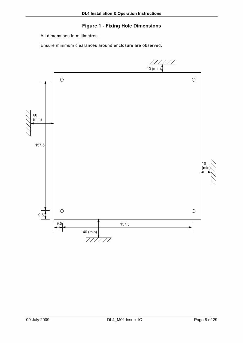
The fixing holes can either be pre-drilled using the dimensions given in Figure [1], orthe base plate can be used as a template.
Fixing screws may be up to 3.5 mm diameter (No. 8) and must be pan-head. Note theeffective “thickness” of the logger is 10mm.
NB. Ensure sufficient clearance below the logger for cable entry via the conduitconnectors, and to the left for the RS232 connection.
DL4 Installation & Operation Instructions
09 July 2009 DL4_M01 Issue 1C Page 8 of 29
Figure 1 - Fixing Hole Dimensions
All dimensions in millimetres.
Ensure minimum clearances around enclosure are observed.
157.5
157.5
40 (min)
60(min)
10 (min)
10(min)
9.5
9.5
DL4 Installation & Operation Instructions
09 July 2009 DL4_M01 Issue 1C Page 9 of 29
2.3 WiringAll cabling must enter the logger through the enclosure base via the bottom face. Three20 mm diameter knock-outs are provided. These are easily removed by using ascrewdriver to lever them out. These holes are designed to take conduit fittings ifrequired.
All connections to the logger circuitry are plug-in. The mains power and inputconnections use plug-in screw terminal blocks. If the logger is to be commissioned at alater date, the mains and input connections can be left unplugged if desired.
NB. Refer to the safety warning in section 1.2. It is important that the 'E' terminal ofTB1 is earthed.
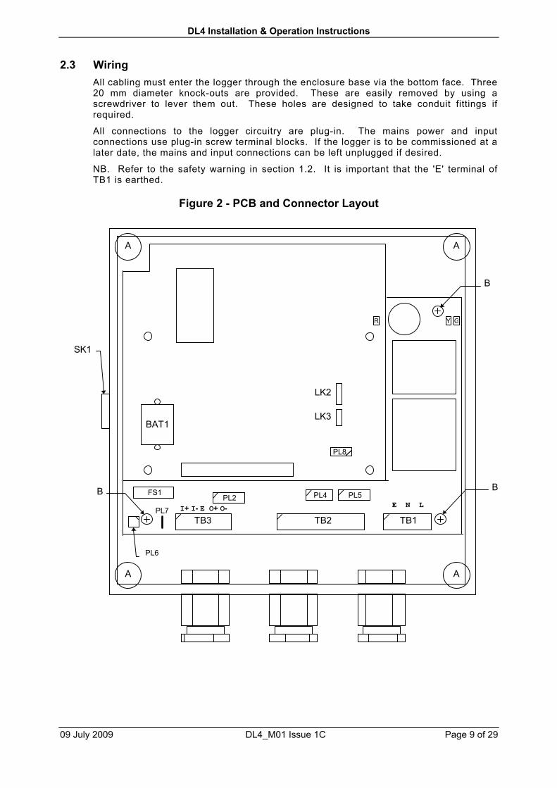
Figure 2 - PCB and Connector Layout
PL5PL4PL2
GYR
TB3 TB2 TB1
FS1
PL6
BAT1
LK2
LK3
A A
A A
B B
B
SK1
PL7
PL8
I+ I- E O+ O- E N L
DL4 Installation & Operation Instructions
09 July 2009 DL4_M01 Issue 1C Page 10 of 29
NB. In the above figure, holes marked ‘A’ are for the screws that fix the logger to thewall. Holes marked ‘B’ are for the screws that fix the logger PCB sub-assemblyto the enclosure.
NB. Not all connectors shown will be fitted to the logger PCB. The actual connectorsfitted will depend on which options have been ordered.
2.3.1 Mains
This connects via the 3-way terminal block TB1. The mains Live, Neutral and Earthconnections are labelled L, N and E respectively. TB1 is a 2-part plug-in screw terminalblock.
Typical power taken will not exceed 3 Watts and a supply spur fused at 3A isrecommended.
Note that the DL4 is designed for operation on a fixed voltage, normally 230 volts AC(nominal).
2.3.2 Inputs
These connect via the 8-way terminal block TB2. The inputs are marked 1 to 4, and thecommon earth terminals are marked ‘-‘. TB2 is a 2-part plug-in screw terminal block.
Screened "Twisted Pair" cables are preferred for wiring up the inputs. A screenedmulti-core cable is a suitable alternative. Unscreened cable may be suitable for someinstallations.
The screen or screens of the input cables should be wired to the earth spade connector(PL7) next to TB3. The length of the tail from the screen to the earth tag should be keptas short as possible (less than 2 cm).
Cable runs of up to 1000m should be possible. With long runs, thicker cable may beneeded to minimize the cable resistance.
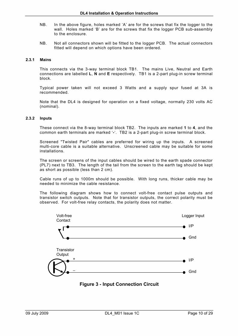
The following diagram shows how to connect volt-free contact pulse outputs andtransistor switch outputs. Note that for transistor outputs, the correct polarity must beobserved. For volt-free relay contacts, the polarity does not matter.
Figure 3 - Input Connection Circuit
I/P
Gnd
Logger InputVolt-freeContact
I/P
Gnd
TransistorOutput
+
–

DL4 Installation & Operation Instructions
09 July 2009 DL4_M01 Issue 1C Page 11 of 29
2.3.3 Telephone
If the optional integral modem is fitted, it will be located on the underside of the mainPCB underneath TB2 (this is not illustrated in Figure [2]). The modem has an RJ12socket on the front for connection to the telephone line. A 3m lead with an RJ12 plugon one end and a standard BT 431A plug on the other is provided with the modem. If alonger lead is required, the one provided can be extended with a normal telephoneextension lead.
2.3.4 Network
This connects via the 5-way terminal block TB2. The inputs are marked I + and -, theoutputs are marked O + and - and the common earth terminal is marked E. TB3 is a 2-part plug-in screw terminal block.
The network uses RS485 signalling, which is a physical link standard for communicatingserial data over long distances ('long range RS232').
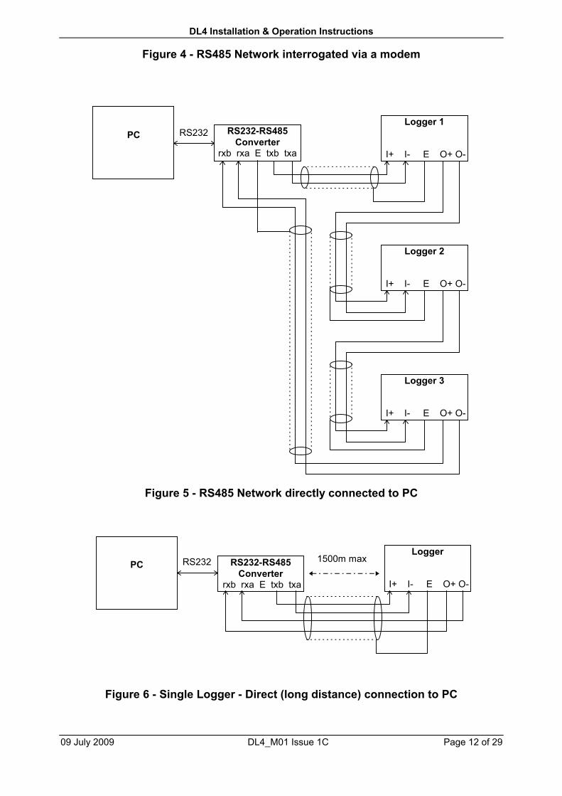
Screened "Twisted Pair" cables are strongly recommended for wiring up the RS485network. The RS485 network is actually a chain, with the O+ and O- of one loggerconnected to the I+ and I- inputs respectively of the next logger in the chain.
The screen of the network cables should be wired to the common earth terminal onTB3. The length of the tail from the screen should be kept as short as possible (lessthan 2 cm). Cable runs of up to 1500m should be possible.
The following diagrams show the different ways of connecting up loggers using theRS485 interface. Note that in all cases, the correct polarity of the Receive andTransmit signals must be observed.
NB If connecting to the logger network at RS232 levels (eg. PC or externalmodem), then connection should be via the Remote Communications Port(PL2). The set-up is then similar to Figure [4].
Logger 1(with Modem)
I+ I- E O+ O-
TelephoneNetwork
Logger 2
I+ I- E O+ O-
Logger 3
I+ I- E O+ O-
DL4 Installation & Operation Instructions
09 July 2009 DL4_M01 Issue 1C Page 12 of 29
Figure 4 - RS485 Network interrogated via a modem
Figure 5 - RS485 Network directly connected to PC
Figure 6 - Single Logger - Direct (long distance) connection to PC
PC RS232-RS485Converter
rxb rxa E txb txa
Logger 1
I+ I- E O+ O-
RS232
Logger 2
I+ I- E O+ O-
Logger 3
I+ I- E O+ O-
PC RS232-RS485Converter
rxb rxa E txb txa
Logger
I+ I- E O+ O-
RS232 1500m max

DL4 Installation & Operation Instructions
09 July 2009 DL4_M01 Issue 1C Page 13 of 29
2.3.5 Cable Types
Screened cables are recommended for all external connections for the logger. Apartfrom that, the type of cable used is not critical, and the terminal blocks will accept awide range of types and sizes. However, for users requiring examples of suitablecables, the following table gives details of some specific types.
Mains Cables Conduit cables 24/0.2 (0.75 mm2) Tri-Rated(BS6231, CSA TEW, UL 1015)(Eg. RS 364-354)
3-core cable 24/0.2 (0.75 mm2) (BS6500) (Eg.RS 378-094)
Pulse / Status Inputs Conduit cables 16/0.2 (0.5 mm2) Tri-Rated(BS6231, CSA TEW, UL 1015)(Eg. RS 364-281)
Twisted-Pair(Screened)
7/0.254 (22 AWG)(Eg. RS 360-649)
Multi-Core Screened 7/0.2 (0.2 mm2) (Eg. RS 367-454)
RS485 LAN Cables Twisted-Pair(Screened)
7/0.254 (22 AWG)(Eg. RS 360-649)

DL4 Installation & Operation Instructions
09 July 2009 DL4_M01 Issue 1C Page 14 of 29
3. COMMISSIONING
The commissioning process consists of :-
• Inspecting the installation
• Powering up the logger and checking basic functionality
• Programming the logger configuration using UCOMM
• Verifying that all sensors / transducers are working, connected and beingrecorded
• Generating an electronic configuration certificate
• Completing a Logger Commissioning Record
Use of the UCOMM commissioning utility requires specialist knowledge of the loggerand its operation.
3.1 Initial Checks
Check that the links on the upper PCB are correctly installed for options supplied.Refer to section 4.5 for details.
Ensure all connectors are properly plugged in.
If the logger is supplied with a UPS, plug in the main battery (connector PL5 - if it is notalready connected). Switch on the mains supply and check that the green and yellowindicators (Mains & Charge) are lit and that the red Heartbeat indicator is flashing. Ifthe UPS option has not been ordered, there will be no main battery and the yellowindicator should be off.
3.2 Configuring using UCOMM
UCOMM is a special configuration software utility available separately from SHM. Thelogger can be pre-configured prior to installation, or it can be configured afterinstallation.
The use of UCOMM is covered in a separate manual.
The logger has a software-programmable configuration that is stored in non-volatileEEPROM memory. This means that it is retained even when all mains and batterypower is disconnected. UCOMM is used to read, display, edit and store thisconfiguration information.
The following parameters should be set or checked using UCOMM :-
1. The Logical Logger Number. For a single-logger installation, the default of 1 canbe used. However for an RS485 network of loggers, each must have a uniqueLogical Logger Number. It is most convenient to program this to 11, 12, 13 etc.in order round the network.
2. The option codes "Option A" and "Option B". These ensure that the loggerfirmware recognises the options fitted. Refer to the UCOMM manual.

DL4 Installation & Operation Instructions
09 July 2009 DL4_M01 Issue 1C Page 15 of 29
3. If any special firmware features, such as "Dial In", "Modem Answer Window" or"Alarms" are required, these must be suitably configured.
4. Channel configuration for each channel. For Digital (Pulse) channels, thiscomprises :-
Logging IntervalPhysical Input numberChannel Size (memory allocation)Pulse pre-scaler valueInitial count
5. If alarms are required, they should be enabled for the alarm channels and thehigh and low thresholds set.
6. The logger time. NB. It is normal for the logger to use the same time referenceall year (eg. Greenwich Mean Time) rather than re-program it for daylight savingtimes.
It is advisable to check the configuration data after installation, even if the logger hasbeen pre-configured. In particular, if the Memory battery has been disconnected at anytime or become discharged, then the logger's clock / calendar will not have a valid time,and the correct time will need to be commissioned before the logger begins logging.
3.3 Verification
Connect a portable PC to the 9-way D connector (SK1) and run the configuration utilityUCOMM on the PC.
Check that the configuration can be read and is correct.
Check that the logger's time and date are correct.
Use the 'Read Channels' function to display all the channel inputs. Where possible,check that each input is operating correctly as follows :-
• For Pulse inputs, the advance in the count can be compared to the advance on themeter registers, or pulses can be artificially induced by shorting the cable at the farend.
• Status inputs can be tested by changing the state of the device being monitored.
If the logger is fitted with a modem, check by dialling from another location that thelogger answers the line and that data can be read.
In normal every day use, the logger will be interrogated by a specialist softwareapplication, such as Stark RT Energy Monitoring Software. The final step is toconfigure the application with details of the logger, and check that it will interrogate thelogger correctly, via modem, LAN or whatever communications medium is being used.
DL4 Installation & Operation Instructions
09 July 2009 DL4_M01 Issue 1C Page 16 of 29
4. DESCRIPTION
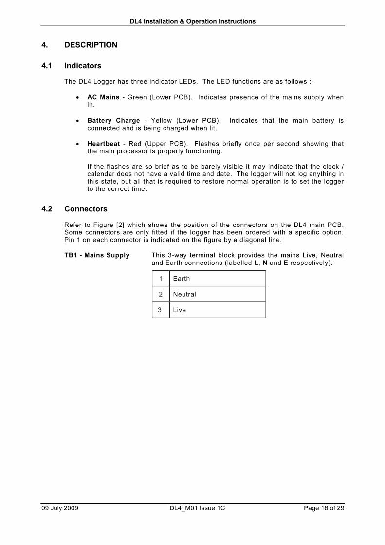
4.1 Indicators
The DL4 Logger has three indicator LEDs. The LED functions are as follows :-
• AC Mains - Green (Lower PCB). Indicates presence of the mains supply whenlit.
• Battery Charge - Yellow (Lower PCB). Indicates that the main battery isconnected and is being charged when lit.
• Heartbeat - Red (Upper PCB). Flashes briefly once per second showing thatthe main processor is properly functioning.
If the flashes are so brief as to be barely visible it may indicate that the clock /calendar does not have a valid time and date. The logger will not log anything inthis state, but all that is required to restore normal operation is to set the loggerto the correct time.
4.2 Connectors
Refer to Figure [2] which shows the position of the connectors on the DL4 main PCB.Some connectors are only fitted if the logger has been ordered with a specific option.Pin 1 on each connector is indicated on the figure by a diagonal line.
TB1 - Mains Supply This 3-way terminal block provides the mains Live, Neutraland Earth connections (labelled L, N and E respectively).
1 Earth
2 Neutral
3 Live
DL4 Installation & Operation Instructions
09 July 2009 DL4_M01 Issue 1C Page 17 of 29
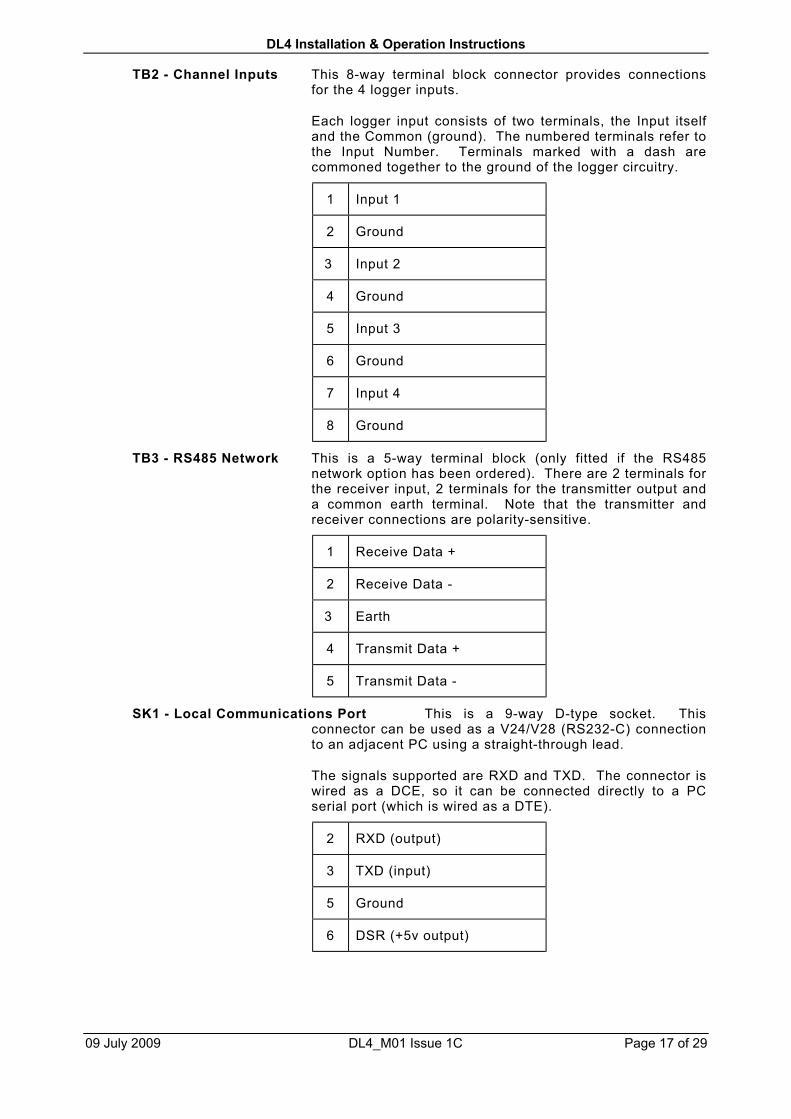
TB2 - Channel Inputs This 8-way terminal block connector provides connectionsfor the 4 logger inputs.
Each logger input consists of two terminals, the Input itselfand the Common (ground). The numbered terminals refer tothe Input Number. Terminals marked with a dash arecommoned together to the ground of the logger circuitry.
1 Input 1
2 Ground
3 Input 2
4 Ground
5 Input 3
6 Ground
7 Input 4
8 Ground
TB3 - RS485 Network This is a 5-way terminal block (only fitted if the RS485network option has been ordered). There are 2 terminals forthe receiver input, 2 terminals for the transmitter output anda common earth terminal. Note that the transmitter andreceiver connections are polarity-sensitive.
1 Receive Data +
2 Receive Data -
3 Earth
4 Transmit Data +
5 Transmit Data -
SK1 - Local Communications Port This is a 9-way D-type socket. Thisconnector can be used as a V24/V28 (RS232-C) connectionto an adjacent PC using a straight-through lead.
The signals supported are RXD and TXD. The connector iswired as a DCE, so it can be connected directly to a PCserial port (which is wired as a DTE).
2 RXD (output)
3 TXD (input)
5 Ground
6 DSR (+5v output)
DL4 Installation & Operation Instructions
09 July 2009 DL4_M01 Issue 1C Page 18 of 29
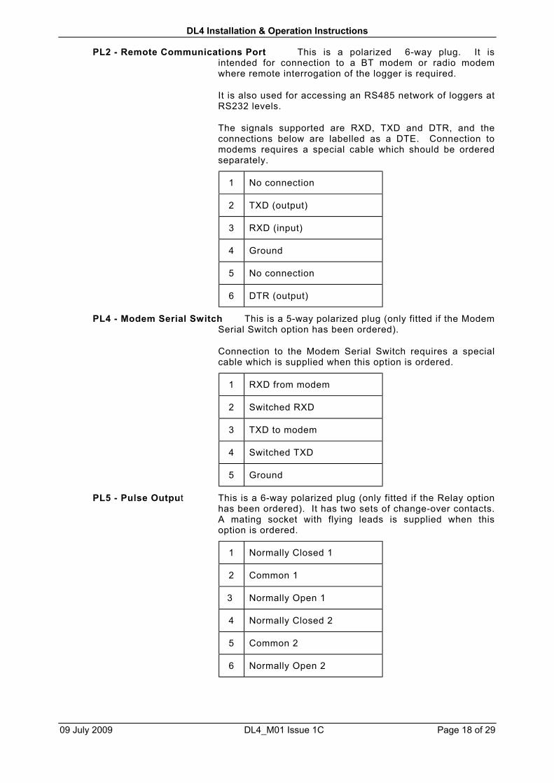
PL2 - Remote Communications Port This is a polarized 6-way plug. It isintended for connection to a BT modem or radio modemwhere remote interrogation of the logger is required.
It is also used for accessing an RS485 network of loggers atRS232 levels.
The signals supported are RXD, TXD and DTR, and theconnections below are labelled as a DTE. Connection tomodems requires a special cable which should be orderedseparately.
1 No connection
2 TXD (output)
3 RXD (input)
4 Ground
5 No connection
6 DTR (output)
PL4 - Modem Serial Switch This is a 5-way polarized plug (only fitted if the ModemSerial Switch option has been ordered).
Connection to the Modem Serial Switch requires a specialcable which is supplied when this option is ordered.
1 RXD from modem
2 Switched RXD
3 TXD to modem
4 Switched TXD
5 Ground
PL5 - Pulse Output This is a 6-way polarized plug (only fitted if the Relay optionhas been ordered). It has two sets of change-over contacts.A mating socket with flying leads is supplied when thisoption is ordered.
1 Normally Closed 1
2 Common 1
3 Normally Open 1
4 Normally Closed 2
5 Common 2
6 Normally Open 2

DL4 Installation & Operation Instructions
09 July 2009 DL4_M01 Issue 1C Page 19 of 29
PL6 - Main Battery This is a polarized 2-way plug. It connects to the 7.2V mainbattery pack which is secured under the sub-chassis.
1 Battery +
2 Battery -
PL7 - Earth This is an earthed single-pole blade connector.
PL8 -Diagnostic This is a polarized 4-way plug. It allows a diagnosticconnection to the transmit and receive data on thecommunication port.
1 Earth
2 TXD
3 RXD
4 +5 volts
4.3 Fuse
The supply from the battery is fitted with a 20mm 500mA quick-blow fuse FS1.
4.4 Batteries
Two batteries are normally provided in the standard unit.
4.4.1 Main Battery
The operating main battery is a 7.2V Nickel-Cadmium 6-cell battery pack and forms partof the logger UPS. This is maintained on constant trickle charge and providesapproximately 5 days of continuous logging after the mains supply fails. Full rechargetakes approximately 24 hours, though the logger will function normally as soon asmains is re-applied. The main battery pack lead is normally NOT plugged in to thelogger as shipped.
4.4.2 Memory Battery
The memory battery is a 3.6V Nickel-Cadmium battery which is also maintained ontrickle charge. This provides memory retention of the logged data for 1 month inbattery-supported RAM (random access memory). The memory battery also powers thecrystal controlled clock calendar circuit. The memory battery is plugged into the uppercircuit board and retained by a cable clip.

DL4 Installation & Operation Instructions
09 July 2009 DL4_M01 Issue 1C Page 20 of 29
4.5 Configuration Links
The logger PCBs have jumper links which are used to further configure the operation ofthe unit. These links are 0.1" pitch shorting jumpers which plug into arrays of 0.1"spaced pins.
The table below shows the links required for various combinations of options. Anyoption combinations not shown are not permitted.
IntegralModem
Extern.Modem
RS485Network
RS485DirectConn.
ModemSerialSwitch
LK 2 LK 3
NORMAL NORMAL
NORMAL NORMAL
NORMAL NORMAL
NET & /MOD NORMAL
NET & MOD NORMAL
(omit) NETACC
NET & /MOD NORMAL
NORMAL NORMAL
(omit) NETACC
NB. For the combination RS485 and External modem, the RS232 connection tothe modem MUST be made via the Remote Communications Port PL2.
DL4 Installation & Operation Instructions
09 July 2009 DL4_M01 Issue 1C Page 21 of 29
5. OPTIONS
5.1 Hardware Options
The functionality of the basic logger can be extended by fitting various options. Thesemust be factory fitted. Loggers cannot be upgraded in the field.
5.1.1 Modems
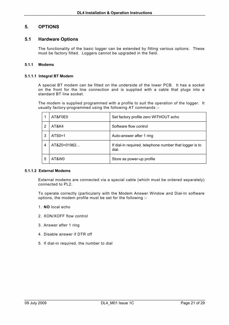
5.1.1.1 Integral BT Modem
A special BT modem can be fitted on the underside of the lower PCB. It has a socketon the front for the line connection and is supplied with a cable that plugs into astandard BT line socket.
The modem is supplied programmed with a profile to suit the operation of the logger. Itusually factory-programmed using the following AT commands :-
1 AT&F0E0 Set factory profile zero WITHOUT echo
2 AT&K4 Software flow control
3 ATS0=1 Auto-answer after 1 ring
4 AT&Z0=01962... If dial-in required, telephone number that logger is todial.
5 AT&W0 Store as power-up profile
5.1.1.2 External Modems
External modems are connected via a special cable (which must be ordered separately)connected to PL2.
To operate correctly (particularly with the Modem Answer Window and Dial-In softwareoptions, the modem profile must be set for the following :-
1. NO local echo
2. XON/XOFF flow control
3. Answer after 1 ring
4. Disable answer if DTR off
5. If dial-in required, the number to dial
DL4 Installation & Operation Instructions
09 July 2009 DL4_M01 Issue 1C Page 22 of 29
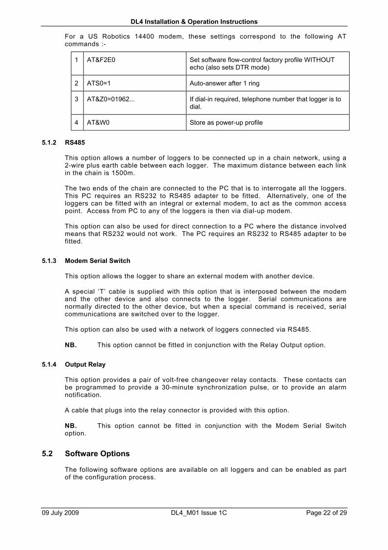
For a US Robotics 14400 modem, these settings correspond to the following ATcommands :-
1 AT&F2E0 Set software flow-control factory profile WITHOUTecho (also sets DTR mode)
2 ATS0=1 Auto-answer after 1 ring
3 AT&Z0=01962... If dial-in required, telephone number that logger is todial.
4 AT&W0 Store as power-up profile
5.1.2 RS485
This option allows a number of loggers to be connected up in a chain network, using a2-wire plus earth cable between each logger. The maximum distance between each linkin the chain is 1500m.
The two ends of the chain are connected to the PC that is to interrogate all the loggers.This PC requires an RS232 to RS485 adapter to be fitted. Alternatively, one of theloggers can be fitted with an integral or external modem, to act as the common accesspoint. Access from PC to any of the loggers is then via dial-up modem.
This option can also be used for direct connection to a PC where the distance involvedmeans that RS232 would not work. The PC requires an RS232 to RS485 adapter to befitted.
5.1.3 Modem Serial Switch
This option allows the logger to share an external modem with another device.
A special ‘T’ cable is supplied with this option that is interposed between the modemand the other device and also connects to the logger. Serial communications arenormally directed to the other device, but when a special command is received, serialcommunications are switched over to the logger.
This option can also be used with a network of loggers connected via RS485.
NB. This option cannot be fitted in conjunction with the Relay Output option.
5.1.4 Output Relay
This option provides a pair of volt-free changeover relay contacts. These contacts canbe programmed to provide a 30-minute synchronization pulse, or to provide an alarmnotification.
A cable that plugs into the relay connector is provided with this option.
NB. This option cannot be fitted in conjunction with the Modem Serial Switchoption.
5.2 Software Options
The following software options are available on all loggers and can be enabled as partof the configuration process.

DL4 Installation & Operation Instructions
09 July 2009 DL4_M01 Issue 1C Page 23 of 29
5.2.1 Modem Answer Window
The Modem Answer Window option is allows a logger to share a telephone line withanother device. If enabled, the logger only answers calls during a pre-programmedtime window. The logger's modem is programmed to answer after only one ring. If theline is shared with a FAX or other modem or answering machine, this must beprogrammed to answer after more than one ring to prevent conflict.
The window start and end time are programmed into the logger as times of day(hh:mm). The window is at the same time every day. If the start and end times areprogrammed with identical times, the logger will answer call at any time of day. If thestart and end times are programmed with the special dummy times 24:00 and 24:01, thelogger will never answer calls.
Note that for testing purposes it possible to get the logger to answer the calls outsidethe normal window if a special ring sequence is used.
5.2.2 Dial In
This is another function that allows a logger to share a telephone line with anotherdevice. With Dial-In, the logger (or network of loggers connected via RS485 links) isprogrammed to dial the number of the controlling PC at a specific time every day. Theactual time of first dial-in is randomized with a delay of up to 10 minutes, and the loggerwill keep trying for up to one hour if it cannot get through. A Dial-In logger can sharethe line with any device without restriction.
The dial-in start time is programmed into the logger as a time of day (hh:mm). If thisthe dial-in time is programmed with the special dummy time 24:00, then dial-in will bedisabled. The telephone number dialled is stored in the modem profile rather than thelogger.
Where an RS485 network is used, the dial-in start time is programmed into the loggerthat is connected to the modem.
5.2.3 Alarms
A logger can be programmed to check its inputs for alarm conditions and notify the userif any parameter goes out of limits.
Each channel in the logger can be programmed with two alarm thresholds (High andLow). The channel can be programmed to generate an alarm if its reading is betweenthe two threshold values or outside the two values. Each channel alarm can also beindividually enabled or disabled.
When an alarm condition is detected, an Alarm Flag is logged alongside the historicaldata.
The logger can be programmed to use latching or non-latching alarms.
Non-latching alarms are simplest - when the channel reading changes to a non-alarmvalue, the channel alarm ceases.
Latched alarms are used if the alarm state is to persist until acknowledged by the user,even if the original alarm condition ceases. The alarm is acknowledged by sending aspecial message to the logger. Acknowledging the alarm will clear the alarm state evenif the channel reading is still at an alarm value. The channel alarm will only be re-activated if the reading subsequently changes from a non-alarm value to an alarmvalue.
The way an alarm is detected depends on the type of channel as follows :-

DL4 Installation & Operation Instructions
09 July 2009 DL4_M01 Issue 1C Page 24 of 29
• Digital channels are checked once per minute (at 00 seconds) using the increase incount since the start of the whole logging period. Note that if the alarm becomesactive during one logging period, it will stay on at least until the end of the nextlogging period (as it is only at this time that it is clear that the channel is not going togenerate an alarm again).
• Status channels are checked once per second.
When alarms occur, the logger can be programmed to notify the user using the optionalrelay and/or by dialling in to a PC. The telephone number dialled is stored in themodem profile rather than the logger.
The relay is provided with contacts that are closed for the non-alarm condition and openfor the alarm condition. This means that if the logger power fails or if the cable is cut,an alarm will be raised.
If notification is via the on-board relay, it is possible to program one of the logger inputsto be used for a reset button or remote contact that will cancel the relay alarm. Oncethe alarm relay has been reset, it will only be re-activated if a new channel alarmoccurs.
For each channel, the alarm type can be configured to :-
• Disabled Channel does not generate alarms
• Inside Window Alarm if channel reading >= Low and <= High
• Outside Window Alarm if channel reading < Low or > High
The High and Low thresholds can be programmed, but the Low threshold cannot begreater than the High threshold (although they can be the same).
Alarm notification is a separate process that can depend on the alarm state of one ormore channels. The following parameters configure the notification process :-
• Latched Mode Enables / Disables latched alarms for all channels
• Alarm Mask Determines which channel(s) generate alarm notifications
• Relay Notif. Enables / Disables notification via optional relay
• Dial-in Notif. Enables / Disables notification via dial-in. If enabled, the loggershould either be fitted with a modem or be on an RS485 networkaccessed via a modem.
• Reset Input Determines which logger input (if any) is used to cancelnotification via the relay
Operation of alarm notification is explained below.
5.2.3.1 Non-Latched Alarms
In this mode, the alarm notification (relay and / or dial-in) can be cancelled (if required),but the occurrence of a new alarm will re-trigger notification. If alarm notification is notcancelled, the notification simply follows the alarm condition. The alarm relay will beactivated :-
1. When any un-masked channel alarm changes from off to on
DL4 Installation & Operation Instructions
09 July 2009 DL4_M01 Issue 1C Page 25 of 29
The alarm relay will be de-activated :-
1. When all un-masked channels alarms are off
2. When the alarm reset input (if configured) is shorted to ground
The logger will begin dialling in :-
1. When any un-masked channel alarm changes from off to on. If the logger and itsmodem control access to an RS485 network, this applies to any un-masked channelin any logger on the network
The logger will stop dialling in :-
1. When all un-masked channels’ alarms are off. If the logger and its modem controlaccess to an RS485 network, this means all un-masked channels in every logger onthe network
2. When the logger receives a “Stop Dialling In” message
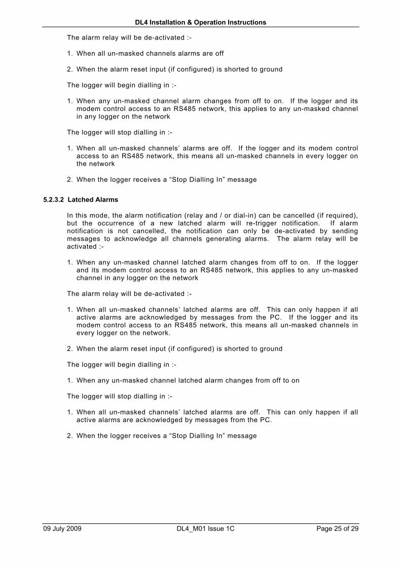
5.2.3.2 Latched Alarms
In this mode, the alarm notification (relay and / or dial-in) can be cancelled (if required),but the occurrence of a new latched alarm will re-trigger notification. If alarmnotification is not cancelled, the notification can only be de-activated by sendingmessages to acknowledge all channels generating alarms. The alarm relay will beactivated :-
1. When any un-masked channel latched alarm changes from off to on. If the loggerand its modem control access to an RS485 network, this applies to any un-maskedchannel in any logger on the network
The alarm relay will be de-activated :-
1. When all un-masked channels’ latched alarms are off. This can only happen if allactive alarms are acknowledged by messages from the PC. If the logger and itsmodem control access to an RS485 network, this means all un-masked channels inevery logger on the network.
2. When the alarm reset input (if configured) is shorted to ground
The logger will begin dialling in :-
1. When any un-masked channel latched alarm changes from off to on
The logger will stop dialling in :-
1. When all un-masked channels’ latched alarms are off. This can only happen if allactive alarms are acknowledged by messages from the PC.
2. When the logger receives a “Stop Dialling In” message
DL4 Installation & Operation Instructions
09 July 2009 DL4_M01 Issue 1C Page 26 of 29
6. MAINTENANCE
In the unlikely event of failure, the entire electronics sub-assembly can be unpluggedand removed very easily to be returned to SHM for repair or exchange.
6.1 Removing the Sub-Chassis
If you need to remove the sub-chassis, first unplug any connectors that are wired up.
The sub-chassis is secured to the base of the enclosure by three 38 mm long self-tapping screws (marked 'B' on Figure [2]). Once these screws are removed, the entiresub-chassis can be removed. The sub-chassis must be manoeuvred so that the 9-wayD-type connector on the left hand side clears the cut-out in the base of the enclosure.
Replacement is the reverse of the removal procedure. When manoeuvring into position,ensure that the 9-way D-type connector on the left hand side engages in its cut-out.
6.2 Battery Life
The batteries are maintained on low trickle charge with complete discharge occurringonly rarely when there are extended power cuts. Under these conditions the batteriescan be expected to last for a period in excess of 5 years.
6.3 Battery Replacement
When the main battery requires changing the sub-chassis must be removed from themain enclosure to release the battery. Removal of mains supply and main battery willcause the logger to stop logging. When the main battery is replaced the logger shouldnot lose data or time since these are maintained by the memory battery.
The main battery will support time and data retention while the memory battery ischanged.
If both the main battery and the memory battery are disconnected in the absence ofmains power, then the logger will lose memory of its logged data and the clock will stop.However, it will not lose its personality profile which is maintained permanently inEEPROM memory.
NB. If the clock stops because of removal of the battery, then the logger will needto have the time and date re-commissioned before it will start logging again.
When changing one or both batteries the personality profile should be checked with alocal portable PC first, and confirmed to be the same after the installation is complete.The calendar clock setting should also be checked and reset if necessary.
DL4 Installation & Operation Instructions
09 July 2009 DL4_M01 Issue 1C Page 27 of 29
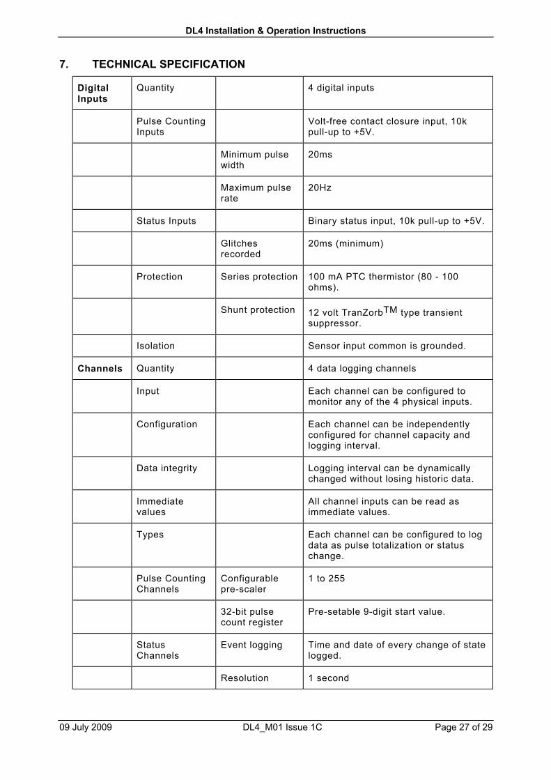
7. TECHNICAL SPECIFICATION
DigitalInputs
Quantity 4 digital inputs
Pulse CountingInputs
Volt-free contact closure input, 10kpull-up to +5V.
Minimum pulsewidth
20ms
Maximum pulserate
20Hz
Status Inputs Binary status input, 10k pull-up to +5V.
Glitchesrecorded
20ms (minimum)
Protection Series protection 100 mA PTC thermistor (80 - 100ohms).
Shunt protection 12 volt TranZorbTM type transientsuppressor.
Isolation Sensor input common is grounded.
Channels Quantity 4 data logging channels
Input Each channel can be configured tomonitor any of the 4 physical inputs.
Configuration Each channel can be independentlyconfigured for channel capacity andlogging interval.
Data integrity Logging interval can be dynamicallychanged without losing historic data.
Immediatevalues
All channel inputs can be read asimmediate values.
Types Each channel can be configured to logdata as pulse totalization or statuschange.
Pulse CountingChannels
Configurablepre-scaler
1 to 255
32-bit pulsecount register
Pre-setable 9-digit start value.
StatusChannels
Event logging Time and date of every change of statelogged.
Resolution 1 second
DL4 Installation & Operation Instructions
09 July 2009 DL4_M01 Issue 1C Page 28 of 29
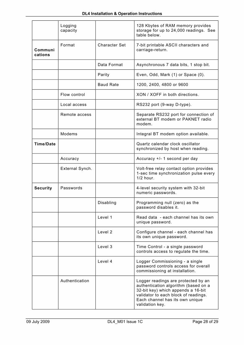
Loggingcapacity
128 Kbytes of RAM memory providesstorage for up to 24,000 readings. Seetable below.
Communications
Format Character Set 7-bit printable ASCII characters andcarriage-return.
Data Format Asynchronous 7 data bits, 1 stop bit.
Parity Even, Odd, Mark (1) or Space (0).
Baud Rate 1200, 2400, 4800 or 9600
Flow control XON / XOFF in both directions.
Local access RS232 port (9-way D-type).
Remote access Separate RS232 port for connection ofexternal BT modem or PAKNET radiomodem.
Modems Integral BT modem option available.
Time/Date Quartz calendar clock oscillatorsynchronized by host when reading.
Accuracy Accuracy +/- 1 second per day
External Synch. Volt-free relay contact option provides1-sec time synchronization pulse every1/2 hour.
Security Passwords 4-level security system with 32-bitnumeric passwords.
Disabling Programming null (zero) as thepassword disables it.
Level 1 Read data - each channel has its ownunique password.
Level 2 Configure channel - each channel hasits own unique password.
Level 3 Time Control - a single passwordcontrols access to regulate the time.
Level 4 Logger Commissioning - a singlepassword controls access for overallcommissioning at installation.
Authentication Logger readings are protected by anauthentication algorithm (based on a32-bit key) which appends a 16-bitvalidator to each block of readings.Each channel has its own uniquevalidation key.

DL4 Installation & Operation Instructions
09 July 2009 DL4_M01 Issue 1C Page 29 of 29
Comms. Data transmission is verified by alongitudinal parity check code on eachpacket (maximum 250 characters).
Electrical External supply 240V AC +/- 15%
Powerconsumption
3VA (maximum)
Main Battery 7.2V NiCad (if UPS option fitted).
Endurance 120 hours sustained logging operationin the absence of external power.
Memory Battery 3.6V NiCad
Endurance 35 days of retention for logged dataand calendar clock.
Wiring Connectors Terminal Blocks Two-part terminal blocks allow pre-wiring of enclosure prior to fitting ofelectronic sub-chassis, and easymaintenance.
Enclosure Construction Two parts. Base and cover.
Material Polycarbonate.
Fastening 4 cover screws. Can be drilled to fit aseal.
Mounting 4-hole wall mounting.
Cable entry Three 20mm conduit knock-outs forbottom entry of cables.
Dimensions Width 175 mm
Height 175 mm
Depth 100 mm
Weight 1 kg.
Environmental IP 51
Logging memory is allocated on a per-channel basis in blocks of 3000 readings. Thisallows four 6000-reading channels or one 24,000 reading channel or any othercombination.
Data logging times for standard 128k logger configured as four equal-memorychannels:-
Logging Interval (mins) 1 2 5 10 15 20 30 60
Duration (days) 4 8 20 41 62 83 125 250