Embed Size (px)
Citation preview

(English) DM-AL0001-09
ALFINESG-S705SG-S505
SM-S705MU-S705
SW-S705ST-S705-RBL-S705-LSC-S705
NexusSG-8R60SG-C6060-8RSG-C6060-8VSG-C6060-8CSG-C6060-8DSG-C6060-8CDSG-C6061-8RSG-C6061-8VSG-C6061-8CSG-C6061-8DSG-C6061-8CD
SC-MT800SM-BTR1SM-BTR2BT-DN110SM-BMR1 (Ver.2.0.0 or above)SM-BMR2BM-DN100SM-JC40SM-JC41EW-SD50EW-SD50-ISM-EWC2SM-BCR1SM-BCR2SM-BCC1
Dealer's Manual
ROAD MTB Trekking
City Touring/ Comfort Bike
URBAN SPORT E-BIKE

2
CONTENTS
IMPORTANT NOTICE ............................................................................................. 4
TO ENSURE SAFETY ............................................................................................... 5
LIST OF TOOLS TO BE USED ................................................................................ 16
INSTALLATION ..................................................................................................... 18Component names and example of positioning ......................................................................................18
Installation of the motor unit to the hub (MU-S705) ..............................................................................22
Installation of the disc brake rotor ...........................................................................................................25
Installation of the hub to the frame .........................................................................................................27
Installing the system information display (SC-S705) ................................................................................30
Installing the system information display (SC-MT800) .............................................................................31
Installation of the dual control lever: Drop handlebar (ST-S705-R/BL-S705-L) ......................................................................................................33
Installation of the shifting switch: Flat handlebar (SW-S705) .................................................................35
Installation of the battery .........................................................................................................................36
CONNECTION OF THE ELECTRIC WIRES ............................................................. 40Overall wiring diagram ..............................................................................................................................40
Connecting to the dual control lever ........................................................................................................46
Connection to the shifting switch/system information display ...............................................................47
Connection of junction ..............................................................................................................................49
OPERATION .......................................................................................................... 59Displaying and operating the system information display (SC-MT800) ..................................................59
Error message .............................................................................................................................................62
About wireless functions (SC-MT800) .......................................................................................................63

3
CHARGING THE BATTERY ................................................................................... 66Names of parts ...........................................................................................................................................66
Charging the battery .................................................................................................................................68
When charging is not possible ..................................................................................................................70
CONNECTION AND COMMUNICATION WITH DEVICES .................................... 73Settings customizable in E-TUBE PROJECT ...............................................................................................73
Connecting to a PC .....................................................................................................................................74
MAINTENANCE .................................................................................................... 76Battery level indicator ................................................................................................................................76
System power reset ....................................................................................................................................76
Troubleshooting .........................................................................................................................................76
Adjusting the motor unit (connection and communication with PC) ....................................................77
Adjusting the motor unit (connection and communication with smartphone or tablet) ................................................................79
Disassembling the bracket body and lever body .....................................................................................81
Assembly of the switch unit ......................................................................................................................82
Assembly of the bracket body and lever body .........................................................................................84
In the case of 8-speed internal geared hub (Oil maintenance kit: Y00298010) .....................................85
In the case of 11-speed internal geared hub (Oil maintenance kit: Y13098023) ...................................87

4
IMPORTANT NOTICE
IMPORTANT NOTICE
• This dealer’s manual is intended primarily for use by professional bicycle mechanics. Users who are not professionally trained for bicycle assembly should not attempt to install the components themselves using the dealer’s manuals. If any part of the information on the manual is unclear to you, do not proceed with the installation. Instead, contact your place of purchase or a local bicycle dealer for their assistance.
• Make sure to read all instruction manuals included with the product.
• Do not disassemble or modify the product other than as stated in the information contained in this dealer’s manual.
• All dealer’s manuals and instruction manuals can be viewed on-line on our website (http://si.shimano.com).
• Please observe the appropriate rules and regulations of the country, state or region in which you conduct your business as a dealer.
• The Bluetooth® word mark and logos are registered trademarks owned by Bluetooth SIG, Inc. and any use of such marks by SHIMANO INC. is under license. Other trademarks and trade names are those of their respective owners.
For safety, be sure to read this dealer’s manual thoroughly before use, and follow it for correct use.
The following instructions must be observed at all times in order to prevent personal injury and physical damage to equipment and surroundings.The instructions are classified according to the degree of danger or damage which may occur if the product is used incorrectly.
DANGER
Failure to follow the instructions will result in death or serious injury.
WARNING
Failure to follow the instructions could result in death or serious injury.
CAUTION
Failure to follow the instructions could cause personal injury or physical damage to equipment and surroundings.

5
TO ENSURE SAFETY
TO ENSURE SAFETY
DANGER
Be sure to also inform users of the following:Be sure to observe the following instructions in order to avoid burns or other injury from fluid leakage, overheating, fire, or explosion.
�Lithium ion battery
• Use the designated charger to charge the battery. If any non-specified items are used, fire, overheating or leakage may occur.
• Do not heat the battery or throw it into fire. If this is not observed, fire or bursting may occur.
• Do not deform, modify, disassemble or apply solder directly to the battery. Do not leave the battery in places which may exceed 60 °C in temperature, such as places which are exposed to direct sunlight inside vehicles on hot days or near stoves. If this is not observed, leakages, overheating or bursting may cause fire, burns, or other injuries.
• Do not connect the (+) and (-) terminals with metallic objects. Do not carry or store the battery together with metallic objects such as necklaces or hairpins. If this is not observed, short-circuits, overheating, burns or other injury may occur.
• If any liquid leaking from the battery gets into the eyes, immediately wash the affected area with clean water without rubbing the eyes, and then seek medical attention.
�Battery charger/Battery charger cord
• Do not get the charger wet or use it while it is wet, and do not touch or hold it with wet hands. If this is not observed, problems with operation or electric shocks may occur.
• Do not cover the charger with cloths while it is in use. If this is not observed, heat may build up and the case may become deformed, or fire or overheating may occur.
• Do not disassemble or modify the charger. If this is not observed, electric shocks or injury may occur.
• Use the charger at the specified power supply voltage only. If a power supply voltage other than that specified is used, fire, explosions, smoke, overheating, electric shocks or burns may occur.
• Do not touch metallic parts of the charger or the AC adapter if there is a lightning storm. If lightning strikes, electric shocks may occur.
SM-BCR2: Battery charger for SM-BTR2/BT-DN110 SM-BTR2/BT-DN110: Lithium ion battery (built-in type)
• Use an AC adapter with a USB port with a voltage of 5.0Vdc and with a current equal to or higher than 1.0Adc. If the one with a current lower than 1.0A is used, the AC adapter may heat up, potentially causing a fire, smoke, overheating, destruction, electric shock, or burns.

6
TO ENSURE SAFETY
WARNING
• Be sure to follow the instructions provided in the manuals when installing the product.It is recommended to use genuine Shimano parts only. If parts such as bolts and nuts become loose or damaged, the bicycle may suddenly fall over, which may cause serious injury.In addition, if adjustments are not carried out correctly, problems may occur, and the bicycle may suddenly fall over, which may cause serious injury.
• Be sure to wear safety glasses or goggles to protect your eyes while performing maintenance tasks such as replacing parts.
• After reading the dealer's manual thoroughly, keep it in a safe place for later reference.
Be sure to also inform users of the following: • Intervals between maintenance depend on the use and riding circumstances. Clean the chain with an appropriate chain cleaner regularly. Never use alkali based or acid based solvents, such as rust cleaners. If those solvents are used the chain might break and cause serious injury.
• Check that the wheels are fastened securely before riding the bicycle. If the wheels are loose in any way, they may come off the bicycle and serious injury may result.
• Check the chain for any damage (deformation or crack), skipping, or other abnormalities such as unintended gear shifting. If any problems are found, consult a dealer or an agency. The chain may break, and you may fall.
�Lithium ion battery • Do not place the battery into fresh water or sea water, and do not allow the battery terminals to get wet. If this is not observed, fire, bursting or overheating may occur.
• Do not use the battery if it has any noticeable scratches or other external damage. If this is not observed, bursting, overheating or problems with operation may occur.
• Do not throw or subject the battery to strong shock. If this is not observed, bursting, overheating or problems with operation may occur.
• Do not use the battery if leakages, discoloration, deformation or any other abnormalities occur. If this is not observed, bursting, overheating or problems with operation may occur.
• If any leaked fluid gets on your skin or clothes, wash it off immediately with clean water. The leaked fluid may damage your skin.
SM-BTR1: Lithium ion battery (external type) • If charging is not complete after 1.5 hours, stop charging. If this is not observed, fire, bursting or overheating may occur.
• The operating temperature ranges for the battery are given below. Do not use the battery in temperatures outside these ranges. If the battery is used or stored in temperatures which are outside these ranges, fire, injury or problems with operation may occur.1. During discharge: –10°C - 50°C 2. During charging: 0°C - 45°C
SM-BTR2/BT-DN110: Lithium ion battery (built-in type) • If the battery does not become fully charged after 4 hours, stop charging. If this is not observed, fire, bursting or overheating may occur.
• The operating temperature ranges for the battery are given below. Do not use the battery in temperatures outside these ranges. If the battery is used or stored in temperatures which are outside these ranges, fire, injury or problems with operation may occur.1. During discharge: –10°C - 50°C2. During charging: 0°C - 45°C

7
TO ENSURE SAFETY
�Battery charger/Battery charger cord SM-BCR1: Battery charger for SM-BTR1
• Hold the power plug when connecting or disconnecting the plug. Failure to do so may cause a fire or electric shock.
• If the following occurs, stop using the device and contact a dealer. A fire or electric shock may occur.* If heat or acrid-smelling smoke is coming out from the power plug.* There may be a bad connection inside the power plug.
• Do not overload the electrical outlet with appliances beyond its rated capacity, and use only a 100 - 240V AC electrical outlet. If the electrical outlet is overloaded by connecting too many appliances using adapters, overheating resulting in fire may occur.
• Do not damage the power cord or power plug. (Do not damage, process, let near hot objects, bend, twist or pull them; do not place heavy objects on top or bundle them tightly.) If they are used while damaged, fire, electric shocks or short-circuits may occur.
• Do not use the charger with commercially-available electrical transformers designed for overseas use, as they may damage the charger.
• Always be sure to insert the power plug as far as it will go. If this is not observed, fire may occur.
SM-BCR2: Battery charger for SM-BTR2/BT-DN110 • Do not use any USB cable other than the USB cable which is supplied with the PC linkage device. This may cause a charging error, fire, or failure to connect to PC due to overheating.
• Do not connect the charger to PC when it is on standby. This may cause a PC failure depending on its specifications.
• When connecting or disconnecting the USB cable or the charger, be sure to hold the cable by the plug. Failure to do so may cause a fire or electric shock. If the following occurs, stop using the device and contact a dealer. A fire or electric shock may occur.* If heat or acrid-smelling smoke is coming out from the power plug.* There may be a bad connection inside the power plug.
• If it thunders while charging with an AC adapter with a USB port, do not touch the device, bicycle, or the AC adapter. If lightning strikes, electric shocks may occur.
• Use an AC adapter with a USB port with a voltage of 5.0 Vdc and with a current equal to or higher than 1.0 Adc. If the one with a current lower than 1.0Adc is used, a charge error may occur or the AC adapter may heat up, leading to a fire.
• Do not use a USB hub when connecting the cable to a computer USB port. This may cause a charging error or fire due to overheating.
• Be careful not to damage the charging cable. (Do not damage, process, let near hot objects, bend, twist or pull them; do not place heavy objects on top or bundle them tightly.) If they are used while damaged, fire, electric shocks or short-circuits may occur.
�Brake • Each bicycle may handle slightly differently depending on the model. Therefore, be sure to learn the proper braking technique (including brake lever pressure and bicycle control characteristics) and operation of your bicycle. Improper use of your bicycle's brake system may result in a loss of control or a fall, which could lead to severe injury. For proper operation, consult a professional bicycle dealer or the bicycle's owner's manual. It is also important to practice riding and braking, etc.
• If the front brake is applied too strongly, the wheel may lock and the bicycle may fall forward, and serious injury may result.
• Always make sure that the front and rear brakes are working correctly before riding the bicycle.
• The required braking distance will be longer during wet weather. Reduce your speed and apply the brakes early and gently.
• If the road surface is wet, the tires will skid more easily. If the tires skid, you may fall off the bicycle; therefore, to avoid this, reduce your speed and apply the brakes early and gently.

8
TO ENSURE SAFETY
�Disc brake • Please make sure to keep your fingers away from the rotating disc brake rotor. The disc brake rotor is sharp enough to inflict severe injury to your fingers if caught in the openings of the disc brake rotor while it is moving.
• The calipers and disc brake rotor will become hot when the brakes are operated; do not touch them while riding or immediately after dismounting from the bicycle. Otherwise you may get burned.
• Be careful not to allow any oil or grease to get onto the disc brake rotor and brake pads. Otherwise the brakes may not work correctly.
• If any oil or grease gets on the brake pads, consult a dealer or an agency. Otherwise the brakes may not work correctly.
• If noise occurs during brake operation, the brake pads may have been worn down to the usable limit. After checking that the temperature of the brake system has cooled down sufficiently, check that the thickness of each pad is 0.5mm or more. Or, consult a dealer or an agency.
0.5mm2mm
• If the disc brake rotor is cracked or deformed, immediately stop using the brakes and consult a dealer or an agency.
• If the disc brake rotor becomes worn down to a thickness of 1.5mm or less, or if the aluminum surface appears, immediately stop using the brakes and consult a dealer or an agency. The disc brake rotor may break, and you may fall off the bicycle.
For Installation to the Bicycle, and Maintenance: • When installing the hub to the frame, be sure to install the correct non-turn washers to the left and right sides, and securely tighten the hub nuts to the specified torques. If the non-turn washer is installed only on one side or the hub nut is not fully tightened, the non-turn washer may come off, causing the hub axle and the motor unit to turn, which in turn may cause the electric wire to be disconnected or damage the motor unit.
• Assemble the wheel with 3x or 4x spoke lacing. Do not spoke the wheel radially. Otherwise, the spokes or the wheel may get damaged, or noise may occur when braking.
�SG-S705 • For SG-S705, be sure to insert a rotor spacer when installing the disc brake rotor. Otherwise, the disc brake rotor may rattle, causing noise or braking failure.
�Coaster brake hub • When using a reversed fork end, use a chain adjuster to remove excess slack from the chain.

9
TO ENSURE SAFETY
CAUTION
Be sure to also inform users of the following:
�Lithium ion battery
• Store the battery in a safe place away from the reach of infants and pets.
SM-BCR1: Battery charger for SM-BTR1 • Disconnect the power plug from the electrical outlet before cleaning the charger.
SM-BCR2: Battery charger for SM-BTR2/BT-DN110 • Disconnect the USB cable when performing maintenance.
SM-BTR1: Lithium ion battery (external type) • If not using the battery for long periods, remove it and store it away in a safe place.
SM-BTR2/BT-DN110: Lithium ion battery (built-in type) • If the unit will not be used for an extended period, store it after charging in cool indoor places (approx. 10 to 20 °C) where the battery will not be exposed to direct sunlight or rain.
�Disc brake • Disc brakes have a burn-in period, and braking force will gradually increase as the burn-in period progresses; therefore, make sure that you are aware of any such increases in braking force when using the brakes during this period. The same thing will happen when the brake pads or disc brake rotor are replaced.
�Coaster brake specifications • Continuous application of the brakes when riding down long slopes will cause the internal brake parts to become very hot, weakening braking performance, and may also cause a reduction in the amount of brake grease inside the brake, leading to problems such as abnormally sudden braking.
• Spin the wheel and confirm that the braking force of the coaster brake is correct.
10
TO ENSURE SAFETY
NOTE
Be sure to also inform users of the following: • Be sure to rotate the crank when carrying out any operations which are related to gear shifting.
• Do not keep connecting and disconnecting the small waterproof connector. It may impair the function.
• Be careful not to get water into the terminal.
• The components are designed to be fully waterproofed to withstand wet weather riding conditions; however, do not deliberately place them into water.
• Do not clean the bicycle with a high-pressure washer. If water gets into any of the components, operating problems or rusting may result.
• Handle the product carefully, and avoid subjecting it to any strong shocks.
• Do not use thinners or similar substances to clean the products. Such substances may damage the surfaces.
• Contact the place of purchase for updates of the component software. The most up-to-date information is available on the Shimano website.
• Products are not guaranteed against natural wear and deterioration from normal use and aging.
• For maximum performance we highly recommend Shimano lubricants and maintenance products.
�SG-S705/SG-S505/SG-8R60/SG-C6060-8R/SG-C6060-8V/SG-C6060-8C/SG-C6060-8D/ SG-C6060-8CD/SG-C6061-8R/SG-C6061-8V/SG-C6061-8C/SG-C6061-8D/SG-C6061-8CD • The internal geared hub is not completely waterproof. Avoid using the hub in places where water might get inside and do not use high-pressure water to clean the hub, otherwise the internal mechanism may rust.
• You can shift gears while pedaling, but on rare occasions the pawls and ratchet inside the hub may produce some noise afterwards as part of normal gear shifting operation.
• The internal geared hub has a built-in mechanism to support shifting, and when this support mechanism operates during shifting, noise or vibration may occur. Depending on gear position, gear-shifting may feel different. Noise may also be produced in the 5 to 8th gear for SG-S505/SG-8R60/SG-C6060-8R/SG-C6060-8V/SG-C6060-8C/SG-C6060-8D/SG-C6060-8CD/ SG-C6061-8R/SG-C6061-8V/SG-C6061-8C/SG-C6061-8D/SG-C6061-8CD and 7 to 11th gear for SG-S705 if the crank arms are turned backward or if the bicycle is pushed backward. All of these phenomena occur due to the built-in gear-shifting structure and are not the failure of the internal components.
�Battery charger/Battery charger cord
• Use this instrument under the direction of a safety supervisor or the direction for use. Do not allow physically, sensory, or mentally impaired persons, inexperienced persons, or persons with no required knowledge, including children, to use this product.
• Do not allow children to play near the product.
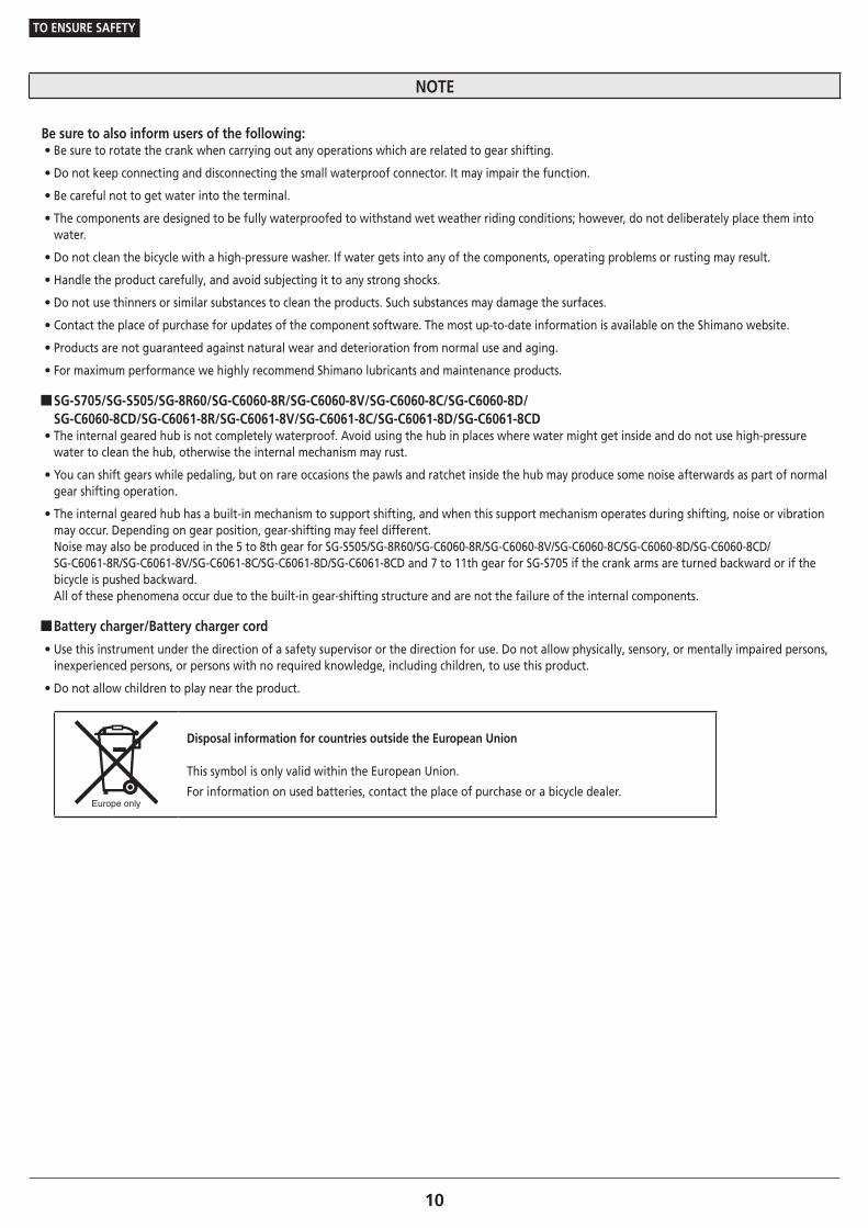
Disposal information for countries outside the European Union
This symbol is only valid within the European Union.
For information on used batteries, contact the place of purchase or a bicycle dealer.

11
TO ENSURE SAFETY
�Lithium ion battery • Lithium-ion batteries are recyclable, valuable resources. For information on used batteries, contact the place of purchase or a bicycle dealer. • Charging can be carried out at any time regardless of the amount of charge remaining. Always be sure to use the special battery charger to charge the battery until it is fully recharged. • The battery is not fully charged at the time of purchase. Before riding, be sure to fully charge the battery. • If the battery has become completely empty, charge it as soon as possible. If you leave the battery without charging it, it will cause the battery to deteriorate. • The battery is an exhaustible item. The battery will gradually lose its capacity to charging after repeated use. If the length of time that the battery can be used becomes extremely short, it has probably reached the end of its life, and so you will need to purchase a new battery. • The life of the battery will vary depending on factors such as the storage method, the usage conditions, the surrounding environment and the characteristics of the individual battery pack. • If storing the battery away for a long period, remove it when the battery level is 50% or higher or when the green indicator is illuminating in order to prolong its useful life; and it is recommended that you charge the battery about every six months. • If the storage temperature is high, the performance of the battery is reduced, and its useable time will be shorter. When you use the battery after a long storage period, store the battery indoors where the battery will not be exposed to direct sunlight or rain. • If the ambient temperature is low, the battery's usable time will be shorter.
SM-BTR1: Lithium ion battery (external type) • When storing the battery away, remove the battery from the bicycle and install the terminal cover first. • The charging time is approximately 1.5 hours. (Note that the actual time will vary depending on the remaining battery charge.) • If the battery feels difficult to insert or remove, apply specified grease (premium grease) to the part that touches the O-ring at the side.
SM-BTR2/BT-DN110: Lithium ion battery (built-in type) • After removing the battery from the bicycle for storage, install a dummy plug. • The charging time of an AC adapter with a USB port is about 1.5 hours, and that of computer USB port type about 3 hours. (Note that the actual time will vary depending on the amount of charge remaining in the battery. Depending on the specifications of the AC adapter, recharging via the AC adapter may require as much time (about 3 hours) as recharging via PC.)
�Battery charger/Battery charger cord • Charge the battery indoors to avoid exposure to rain or wind. • Do not use outdoors or in environments with high humidity. • Do not place the battery charger on dusty floors when using it. • Place the battery charger on a stable surface such as a table when using it. • Do not place any objects on top of the battery charger or its cable. • Do not bundle the cables. • Do not hold the battery charger by the cables when carrying it. • Do not apply excessive tension to the cables. • Do not wash the battery charger or wipe it using detergents. • Use this instrument under the direction of a safety supervisor or the direction for use. Do not allow physically, sensory, or mentally impaired persons, inexperienced persons, or persons with no required knowledge, including children, to use this product. • Do not allow children to play near the product.

12
TO ENSURE SAFETY
SM-BCR2: Battery charger for SM-BTR2/BT-DN110 PC linkage device
• Connect the PC linkage device directly to a computer, without using an intermediate device such as a USB hub. • Do not ride the bicycle while the PC linkage device and cable are still connected to it. • Do not connect two or more of the same units to the same connection point. If this is not done, the units may not operate correctly. • Do not connect or disconnect units again while unit recognition is in progress or after recognition is complete. If this is not done, the units may not operate correctly. Check the procedures which are given in the user's manual for E-TUBE PROJECT when connecting and disconnecting units. • The tightness of the PC link cable will tend to drop after repeated connections and disconnections. If this happens, replace the cable. • Do not connect two or more PC linkage device at the same time. If two or more PC linkage device units are connected, they will not operate correctly. In addition, the PC may need to be restarted if operating errors occur. • PC linkage devices cannot be used while the charger is connected.
For Installation to the Bicycle, and Maintenance: • Be sure to attach dummy plugs to any unused E-TUBE ports. • Be sure to use Shimano original tool TL-EW02 to remove the electric wires. • The motors of the motor unit cannot be repaired. • Contact Shimano for information regarding the shipment of the battery charger to South Korea and Malaysia. • The gears should be periodically washed with a neutral detergent. In addition, cleaning the chain with neutral detergent and lubricating it can be an effective way of extending the life of the gears and the chain. • If chain skipping has started occurring, replace the gears and the chain at a dealer or an agency.
�Internal geared hub • The sprocket should be used from 18T to 23T.
Sprocket
When using chain tensioner 18, 20
When not using chain tensioner 18, 19, 20, 21, 22, 23
• It is recommended that the chainring of the front be set to a gear ratio of 2 to 2.25 for SG-S505/SG-8R60/SG-C6060-8R/SG-C6060-8V/SG-C6060-8C/ SG-C6060-8D/SG-C6060-8CD/SG-C6061-8R/SG-C6061-8V/SG-C6061-8C/SG-C6061-8D/SG-C6061-8CD and 1.8 to 2.0 for SG-S705.
Example)
Gear ratio Front Rear
11-speed 1.8 – 2.045T 23T
39T 20T
8-speed 2 – 2.2545T 20T
39T 18T
• In order to maintain proper performance, it is recommended that you contact the place of purchase or a bicycle dealer to carry out maintenance such as internal oil replacement after riding 1,000km from the start of use and after that, about once every two years (or once about every 5,000km if the bicycle is used very frequently).

13
TO ENSURE SAFETY
�SG-S705 • When you perform oil maintenance, use the SG-S700 OIL or TL-S703 maintenance kit. When you replace the oil, follow the manual for TL-S703. When you replace the seal on the right side, use TL-S704. If SG-S700 OIL is not used, problems such as an oil leakage and gear shifting malfunction may occur.
�SG-S505/SG-8R60/SG-C6060-8R/SG-C6060-8V/SG-C6060-8C/SG-C6060-8D/SG-C6060-8CD/ SG-C6061-8R/SG-C6061-8V/SG-C6061-8C/SG-C6061-8D/SG-C6061-8CD • When you perform oil maintenance, use the WB maintenance oil or the WB maintenance oil set. If the WB maintenance oil is not used, problems such as an oil leakage and gear shifting malfunction may occur.
�Electric wires/Electric wire covers • Secure the electric wires with a zip tie so that they do not interfere with the chainrings, sprockets or tires. • The strength of the adhesive is fairly weak to prevent the paint on the frame from being peeled off when removing the electric wire cover, such as when replacing the electric wires. If the electric wire cover is peeled off, replace it with a new one. When removing the electric wire cover, do not peel it off too vigorously. If so, the paint on the frame will peel off, too. • Do not remove the wire holders which are attached to the built-in type electric wires (EW-SD50-I). The wire holders prevent the electric wires from moving inside the frame.
�Dual control lever • Dummy plugs are installed at the time of shipment from the factory. Do not remove them except when necessary. • When routing the electric wires, take care to ensure that they do not interfere with the brake levers.
�SM-BMR1/Battery mount • This is supported by the firmware versions 2.0.0 and later.
�Coaster brake specifications • If the wheels are not rotating smoothly, you need to replace or grease the brake shoes. Consult the dealer where you made the purchase.
The actual product may differ from the illustration because this manual is intended mainly to explain the procedures for using the product.
For Installation to the Bicycle, and Maintenance:
�Notes on reinstalling and replacing components • When the product is reassembled or replaced, it is automatically recognized by the system to allow operation according to the settings.
• If the system does not operate after reassembly and replacement, follow the system power reset procedure below to check the operation.
• If the component configuration changes or malfunction is observed, use the E-TUBE PROJECT software to update the firmware of each component to the latest version and perform a check again. Also make sure that the E-TUBE PROJECT software is the latest version. If the software is not the latest version, the component compatibility or the product functions may not be available.
�Coaster brake specifications • Use a wheel with 3x or 4x spoke lacing. Wheels with radial lacing cannot be used. Otherwise, the spokes or the wheel may get damaged, or noise may occur when braking.
• If the wheel becomes stiff and difficult to turn, you should replace the brake shoes or lubricate with grease.
• Use only the specified grease for the brake shoes and when using a lubrication kit, remove the brake shoes to avoid contact with the oil.

14
TO ENSURE SAFETY
Be sure to also inform users of the following:
�About used batteries • Lithium-ion batteries are recyclable, valuable resources. For information on used batteries, contact the place of purchase or a bicycle dealer.
�About system power reset • When the system fails to operate, the system may be recovered by resetting the system power.
• After the battery is removed, about one minute is usually required for the system power to reset.
In the case of using SM-BTR1 • Remove the battery from the battery mount. After about one minute, install the battery.
In the case of using SM-BTR2/BT-DN110
• Disconnect the plug from SM-BTR2/BT-DN110. After about one minute, insert the plug.
�Connection and communication with PC
• A PC linkage device can be used to connect a PC to the bicycle (system or components), and E-TUBE PROJECT can be used to carry out tasks such as customizing single components or the whole system and updating firmware. If your versions of E-TUBE PROJECT software and firmware for each component are not up to date there could be problems operating the bicycle. Check the software version and update to the latest version.
PC linkage device E-TUBE PROJECT Firmware
SM-BMR2/SM-BTR2
SM-PCE1/SM-BCR2
Version 2.6.0 or later Version 3.0.0 or later
BT-DN110/BM-DN100 Version 3.0.0 or laterVersion 4.0.0 or later
* Pre-installed firmware is version 4.0.0.
�Connection and communication with smartphone or tablet
• It is possible to customize single components or the system, and update firmware, using E-TUBE PROJECT for smartphones/tablets after connecting the bicycle (system or components) to a smartphone or tablet via Bluetooth LE.
• E-TUBE PROJECT: app for smartphones/tablets
• Firmware: software inside each component
• Disconnect Bluetooth LE when not using E-TUBE PROJECT for smartphones/tablets. Using the system information display without disconnecting Bluetooth LE may result in high battery power consumption.
About compatibility with E-TUBE PROJECT
• For details on compatibility with E-TUBE PROJECT, refer to the following website. (http://e-tubeproject.shimano.com/guide/#guide_list)

LIST OF TOOLS TO BE USED

16
LIST OF TOOLS TO BE USED
LIST OF TOOLS TO BE USED
The following tools are needed for installation, adjustment, and maintenance purposes.
Tool Tool Tool
2mm hexagon wrench 17mm spanner TL-LR10
3mm hexagon wrench Hexalobular[#5] TL-LR15
4mm hexagon wrench Hexalobular[#8] TL-SGE1 (Tools for mounting motor unit to the hub)
5mm hexagon wrench Adjustable wrench Special E-ring removal tool Y6RT68000
10mm spanner Snap ring pliers Plastic mallet
15mm spanner TL-EW02

INSTALLATION

18
INSTALLATION
Component names and example of positioning
INSTALLATION
� Component names and example of positioning
External battery SM-BTR1
Built-in type (SM-JC41)
When using the combination of units in the illustration, make sure to use the system information display, battery and battery mount combinations specified in the table.
System information display Battery Battery mount
SC-S705 SM-BTR1 SM-BMR2
SC-MT800 SM-BTR1 BM-DN100
(A) MU-S705: Motor unit
(B) SG-S705: Internal geared hub 11-speed
(C) SG-S505/SG-8R60/SG-C6060-8R/SG-C6060-8V/SG-C6060-8C/SG-C6060-8D/SG-C6060-8CD/SG-C6061-8R/SG-C6061-8V/SG-C6061-8C/SG-C6061-8D/SG-C6061-8CD: Internal geared hub 8-speed
(D) SC-S705/SC-MT800: System information display
(E) SW-S705: Shifting switch
(F) BL-S705-L: Brake lever
(G) ST-S705-R: Dual control lever
(H) SM-BMR2/BM-DN100: Battery mount
(I) SM-BTR1: Lithium ion battery
(J) EW-SD50-I: Electric wire
(K) SM-JC41: Junction B
NOTE
Make sure to only use the system information display, battery and battery mount combinations specified in the table.
TECH TIPS
Cable length (EW-SD50)
[a] + [b] ≤ 1700mm[c] ≤ 1400mm
(A)(B)(C) (J)(K)
[a]
[b]
(D)
(E)
[c]
(H)
(I)
(F)
(G)
19
INSTALLATION
Component names and example of positioning
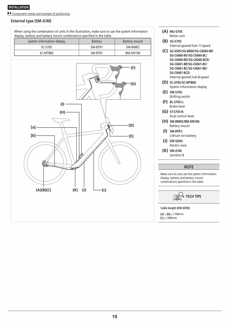
External type (SM-JC40)
When using the combination of units in the illustration, make sure to use the system information display, battery and battery mount combinations specified in the table.
System information display Battery Battery mount
SC-S705 SM-BTR1 SM-BMR2
SC-MT800 SM-BTR1 BM-DN100
(A) MU-S705: Motor unit
(B) SG-S705: Internal geared hub 11-speed
(C) SG-S505/SG-8R60/SG-C6060-8R/SG-C6060-8V/SG-C6060-8C/SG-C6060-8D/SG-C6060-8CD/SG-C6061-8R/SG-C6061-8V/SG-C6061-8C/SG-C6061-8D/SG-C6061-8CD: Internal geared hub 8-speed
(D) SC-S705/SC-MT800: System information display
(E) SW-S705: Shifting switch
(F) BL-S705-L: Brake lever
(G) ST-S705-R: Dual control lever
(H) SM-BMR2/BM-DN100: Battery mount
(I) SM-BTR1: Lithium ion battery
(J) EW-SD50: Electric wire
(K) SM-JC40: Junction B
NOTE
Make sure to only use the system information display, battery and battery mount combinations specified in the table.
TECH TIPS
Cable length (EW-SD50)
[a] + [b] ≤ 1100mm[c] ≤ 1400mm
(A)(B)(C) (J)(K)
[a]
[b]
(D)
(E)
[c]
(H)
(I)
(F)
(G)

20
INSTALLATION
Component names and example of positioning
Built-in battery SM-BTR2/BT-DN110
When using the combination of units in the illustration, make sure to use the system information display, battery and battery mount combinations specified in the table.
System information display Battery
SC-S705 SM-BTR2
SC-MT800 BT-DN110
(A) MU-S705: Motor unit
(B) SG-S705: Internal geared hub 11-speed
(C) SG-S505/SG-8R60/SG-C6060-8R/SG-C6060-8V/SG-C6060-8C/SG-C6060-8D/SG-C6060-8CD/SG-C6061-8R/SG-C6061-8V/SG-C6061-8C/SG-C6061-8D/SG-C6061-8CD: Internal geared hub 8-speed
(D) SM-BTR2/BT-DN110: Lithium ion battery
(E) SC-S705/SC-MT800: System information display
(F) SW-S705: Shifting switch
(G) BL-S705-L: Brake lever
(H) ST-S705-R: Dual control lever
(I) EW-SD50-I: Electric wire
(J) SM-JC41: Junction B
NOTE
Make sure to only use the system information display and battery combinations specified in the table.
TECH TIPS
Cable length (EW-SD50)
[a] + [b] ≤ 1700mm[c] ≤ 1400mm
(A)(B)(C) (I)(J)
[a] [c]
[b]
(E)
(F)
(D)
(G)
(H)

21
INSTALLATION
Component names and example of positioning
Installation of sprocket to the hub (SG-S705/SG-505/SG-8R60/SG-C6060-8R/ SG-C6060-8V/SG-C6060-8C/SG-C6060-8D/SG-C6060-8CD/SG-C6061-8R/ SG-C6061-8V/SG-C6061-8C/SG-C6061-8D/SG-C6061-8CD/SM-S705)
(A)
(B)
(C)
(z)
(D)
Place right-hand dust cap onto the driver on the right side of the hub body.
Next, install the sprocket and secure it in place with the snap ring pliers.
(z) Note the direction
(A) Snap ring pliers
(B) Sprocket
(C) Driver
(D) Right-hand dust cap B
NOTE
This product should only be used with inward assembling sprockets with 18T to 23T.

22To be continued on next page
INSTALLATION
Installation of the motor unit to the hub (MU-S705)
� Installation of the motor unit to the hub (MU-S705)
1
(z)(y)(y) Check that the two ● marks (red) on the
right side of the hub body are aligned.
(y) ● mark (red)
(z) Should be aligned
TECH TIPS
If the two ● marks (red) are not aligned, use the TL-SGE1 to align the two ● marks (red).
Turn clockwise
TL-SGE1

23To be continued on next page
INSTALLATION
Installation of the motor unit to the hub (MU-S705)
2
(B)
(A)
Make sure that the two protrusions on the reverse side of the motor unit are at the initial positions as shown in the illustration on the left.
(A) Reverse side of motor unit
(B) Protrusion
NOTE
Check that the rubber seal is attached. If the rubber seal is not attached, attach as shown in the illustration.
Reverse side of motor unit
Motor unit
Rubber seal
(A)
(A) Shifting switch
NOTE
The motor unit is set at the initial position when it is shipped; therefore, install it without changing the position. If the motor unit may not be at the initial position, push the following shifting switch ten or more times to move the protrusions on the motor unit clockwise (check from the back side of the motor unit). (Check the shifting up and down of the shifting switch in advance as it may have been switched by customization.) If the motor unit is installed off the initial position, some gears may become unavailable and the hub or the motor unit may be damaged.

24
INSTALLATION
Installation of the motor unit to the hub (MU-S705)
3
(x)
(y) (z)
(B) (A)
(C)
(A)
Install the motor unit to the hub so that the ● mark (yellow) on the motor unit is aligned with the ● mark (red) on the hub lock spacer.
After this, gently push the motor unit while turning it slowly to set it correctly until it stops turning on the hub axle.
Next, secure the motor unit by tightening right-hand lock nut B.
(x) ● mark (yellow) on motor unit
(y) ● mark (red) on lock spacer
(z) Outer side
(A) Right-hand lock nut B
(B) Right-hand lock nut A
(C) Motor unit
Tightening torque
6 - 10 N·m
NOTE
Check that the guide of right-hand lock nut A is seated securely in the guide hole on the front of the motor unit.
Motor unit guide hole
Right-hand lock nut A guide
If the tab is out of position, connect the shifting lever, electric wire, system information display, and battery unit to the motor unit before manually shifting gears to 1st.

25
INSTALLATION
Installation of the disc brake rotor
� Installation of the disc brake rotor
Install the disc brake rotor as shown in the illustration.
Center lock type
(A) (B) (C)
(A) Disc brake rotor
(B) Disc brake rotor installation ring
(C) TL-LR10
Tightening torque
40 N·m
SG-S705
(A) (B) (C) (D)
(A) Disc brake rotor
(B) Rotor spacer
(C) Disc brake rotor installation ring
(D) TL-LR15
Tightening torque
40 N·m

26
INSTALLATION
Installation of the disc brake rotor
5 bolt type (with lock washers)
1
Place the disc brake rotor and disc brake rotor lock washers on the hub and tighten in place with the bolts.
(A) Lock washer
(B) Disc brake rotor fixing bolt
Tightening torque
2 - 4 N·m
NOTE
• Fit the lock washers so that the marking "TOP" is visible.
• Ensure that the hooked parts of the lock washer are securely caught on the notches in the disc brake rotor and then tighten on the lock washer with the disc brake rotor fixing bolt. If tightened while the hooked parts are against the surface of the disc brake rotor, the washer and its hooked parts will become deformed.
Hooked part of washer
Notch in disc brake rotor
• The lock washers are not reusable. Always use new lock washers when installing/re-installing the disc brake rotor.
• Use the dedicated disc brake rotor fixing bolts.
(B)
(A)
2
Wear gloves and turn the disc brake rotor clockwise with some force.
Then, tighten the disc brake rotor fixing bolts in the order shown in the illustration.

27To be continued on next page
INSTALLATION
Installation of the hub to the frame
� Installation of the hub to the frame
The method of installing the hub to the frame is the same when the chain tensioner is being used and when it is not being used.
1
Mount the chain on the sprocket, and then set the hub axle into the fork end.
When not using chain tensioner
(A)
(B)
(A) Fork end
(B) Hub axle
When using chain tensioner
(C)
(A)
(B)
(A) Chain tensioner
(B) Hub axle
(C) Fork end
TECH TIPS
When using the chain tensioner, be sure to read the attached instruction manual for the CT-S500 chain tensioner.

28To be continued on next page
INSTALLATION
Installation of the hub to the frame
2
Place non-turn washers and onto the right and left sides of the hub axle.
At this time, turn the motor unit so that the projecting parts of the non-turn washers fit into the grooves of the fork ends.
(A) Non-turn washer (for left-side use)
(B) Motor unit
(C) Groove in fork end
(D) Non-turn washer (for right-side use)
(E) Chainstay
TECH TIPS
• Use a non-turn washer that matches the shape of the fork end. Different non-turn washers are used for the left and right sides.
Mark
• The protrusion should be on the fork end side.
• Install the non-turn washer so that the protrusion fits securely in the fork end groove at the front and back sides of the hub axle.
7R
(D)
(E)
(B)
(C)
(A)
Fork end
Non-turn washer
Mark/Color Size
For right For left
Standard5R/Yellow 5L/Brown θ≤20°
7R/Black 7L/Gray θ≤38°
Reversed 6R/Silver 6L/White θ=0°
Reversed
(Full chain case)5R/Yellow 5L/Brown θ=0°
Vertical 8R/Blue 8L/Green θ=60° - 90°

29
INSTALLATION
Installation of the hub to the frame
3
Take up slack in the chain and secure the wheel to the frame with the hub nut. (A) Non-turn washer
(B) Hub nut
Tightening torque
30 - 45 N·m
NOTE
• When installing parts such as a mudguard stay to the hub axle, install them in the order shown in the illustration below.
Non-turn washer
Mudguard stay
Carrier stayWasher
Hub nut
• When installing the hub to the frame, the chain guard may come off, so check that the chain guard is securely installed. If not properly installed, noise may be generated.
Chain guard
(A)
(B)

30
INSTALLATION
Installing the system information display (SC-S705)
For coaster brakes
(A) (B) (C)
(E)(D)
(A) Brake arm
(B) Clip nut
(C) Clip bolt
(D) Chainstay
(E) Arm clip
� Installing the system information display (SC-S705)
1
(A)Install the rubber spacer to the system information display.
(A) Rubber spacer
2
(A)
Attach to the handle with the included zip tie.
Manually tighten the zip tie completely.
(A) Zip tie
TECH TIPS
Use a handle with a diameter of Ø25.6 to 31.8.

31
INSTALLATION
Installing the system information display (SC-MT800)
� Installing the system information display (SC-MT800)
Replacing the clamp band
(A) (B)
Remove the case mounting bolt with a 2.5mm hexagon wrench and replace the clamp band.
(A) Case mounting bolt
(B) Clamp band
Tightening torque
0.6 N·m
NOTE
If using a handlebar with a thick diameter, reinstall it using the included Ø35mm clamp band.
32
INSTALLATION
Installing the system information display (SC-MT800)
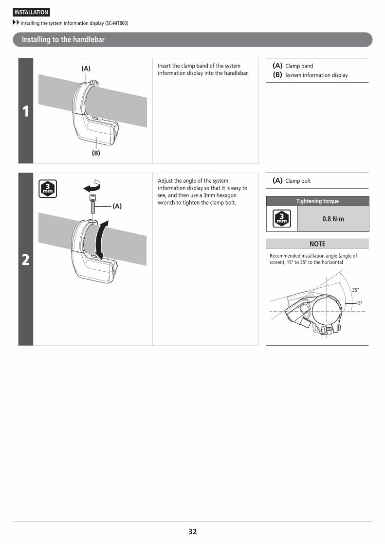
Installing to the handlebar
1
(A)
(B)
Insert the clamp band of the system information display into the handlebar.
(A) Clamp band
(B) System information display
2
(A)
Adjust the angle of the system information display so that it is easy to see, and then use a 3mm hexagon wrench to tighten the clamp bolt.
(A) Clamp bolt
Tightening torque
0.8 N·m
NOTE
Recommended installation angle (angle of screen): 15° to 35° to the horizontal
15°
35°

33
INSTALLATION
Installation of the dual control lever: Drop handlebar (ST-S705-R/BL-S705-L)
� Installation of the dual control lever:
Drop handlebar (ST-S705-R/BL-S705-L)
(A)
(B)
Pull back the bracket cover from the front and use a 5mm hexagon wrench to tighten the fixing nut.
(A) Bracket cover
(B) 5mm hexagon wrench
Tightening torque
6 - 8 N·m
NOTE
Even with the recommended tightening torque, there is a possibility that the carbon handlebars may become damaged and insufficiently tightened. For the appropriate torque value, consult with the manufacturer of the completed bicycle or the manufacturer of the handle.
Installation of the brake cable
Cable to be used
Inner cable SLR outer casing
Ø1.6mm Ø5mmTECH TIPS
Use cables which are long enough so that they still have some slack even when the handlebars are turned as far as they will go to the left and to the right.

34
INSTALLATION
Installation of the dual control lever: Drop handlebar (ST-S705-R/BL-S705-L)
Installation procedures
1 Gently pull the brake lever.
2 (B) (C)
(A)
Pass the inner cable through from directly in front, set the inner cable drum into the cable hook, and then install the outer casing from the opposite side.
(A) Outer casing
(B) Cable hook
(C) Inner cable drum
TECH TIPS
The lever stroke can be smoothly adjusted using the bolt on the top of the bracket body. Check the lever operation while adjusting.

35
INSTALLATION
Installation of the shifting switch: Flat handlebar (SW-S705)
� Installation of the shifting switch: Flat handlebar (SW-S705)
(z)
(A)
Install as shown in the illustration.
(z) Handlebar diameter: 22.2mm
(A) 4mm hexagon wrench
Tightening torque
5 - 7 N·m
TECH TIPS
Use a handlebar grip with an outer diameter of Ø32mm or less.

36To be continued on next page
INSTALLATION
Installation of the battery
� Installation of the battery
In the case of an external battery
Both SM-BMR1 and 2 can be installed using the same procedure. The down tube (under the bottle cage) is used for explanation here, but the mounting location is not limited to this section.
1
Set the battery mount into position.
Use the bottle cage fixing bolt to temporarily install the battery mount onto the bottom of the bottle cage.
Short type Use the included M4 bolts to secure the short type.
Tightening torque
1.2 - 1.5 N·m
Long type Use the bolts which are included with the bottle cage to secure the long type.
TECH TIPS
Refer to the Service Instructions for the bottle cage for details on the tightening torques.
2(z)
Leave a space of 108mm or more at the end of the battery mount.
Check that the battery can be inserted and removed while the bottle cage is installed.
(z) 108mm

37
INSTALLATION
Installation of the battery
3
(A)
Tighten the bolt of the bottle cage to secure the battery mount.
For the long type, use the accessory zip tie to secure the battery mount to the frame.
(A) Zip tie
TECH TIPS
If there is a mounting boss on the frame
If there is a mounting boss on the frame, the battery mount can be secured to the frame with a bolt.
Battery mount mounting bolt (M4 x 15mm)
Tightening torque
1.2 - 1.5 N·m
38
INSTALLATION
Installation of the battery
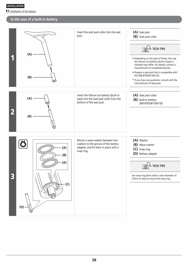
In the case of a built-in battery
1(A)
(B)
Insert the seat post collar into the seat post.
(A) Seat post
(B) Seat post collar
TECH TIPS
• Depending on the type of frame, the way the lithium ion battery (built-in type) is installed may differ. For details, contact a manufacturer of completed bicycles.
• Prepare a seat post that is compatible with DI2 (SM-BTR2/BT-DN110).
* If you have any questions, consult with the manufacturer of seat post.
2
(A)
(B)
Insert the lithium ion battery (built-in type) into the seat post collar from the bottom of the seat post.
(A) Seat post collar
(B) Built-in battery (SM-BTR2/BT-DN110)
3(C)
(D)
(A)
(B)
(A)
Mount a wave washer between two washers to the groove of the battery adapter, and fix them in place with a snap ring.
(A) Washer
(B) Wave washer
(C) Snap ring
(D) Battery adapter
TECH TIPS
Use snap ring pliers (with a claw diameter of 2.0mm or less) to mount the snap ring.

CONNECTION OF THE ELECTRIC WIRES

40
CONNECTION OF THE ELECTRIC WIRES
Overall wiring diagram
CONNECTION OF THE ELECTRIC WIRES
� Overall wiring diagram
External battery type: SM-JC40 (Junction B: external type)
Flat handlebar use
SW-S705
SC-S705SC-MT800
SM-BTR1
SM-BMR1/SM-BMR2/BM-DN100
EW-SD50
EW-SD50
SM-JC40EW-SD50MU-S705(SG-S705)(SG-S505)(SG-8R60)
(SG-C6060-8R)(SG-C6060-8V)(SG-C6060-8C)(SG-C6060-8D)(SG-C6060-8CD)(SG-C6061-8R)(SG-C6061-8V)(SG-C6061-8C)(SG-C6061-8D)(SG-C6061-8CD)

41
CONNECTION OF THE ELECTRIC WIRES
Overall wiring diagram
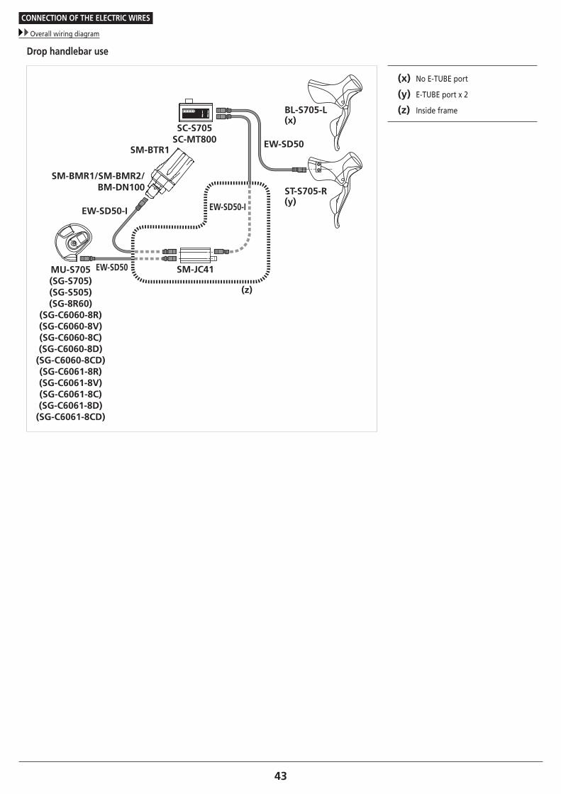
Drop handlebar use
BL-S705-L(y)
EW-SD50
ST-S705-R(z)
SC-S705SC-MT800
SM-BTR1
SM-BMR1/SM-BMR2/BM-DN100
EW-SD50
EW-SD50
SM-JC40EW-SD50MU-S705(SG-S705)(SG-S505)(SG-8R60)
(SG-C6060-8R)(SG-C6060-8V)(SG-C6060-8C)(SG-C6060-8D)(SG-C6060-8CD)(SG-C6061-8R)(SG-C6061-8V)(SG-C6061-8C)(SG-C6061-8D)(SG-C6061-8CD)
(y) No E-TUBE port
(z) E-TUBE port x 2

42
CONNECTION OF THE ELECTRIC WIRES
Overall wiring diagram
External battery type: SM-JC41 (Junction B: built-in type)
Flat handlebar use
(z)
EW-SD50-IEW-SD50-I
SW-S705
SC-S705SC-MT800
SM-BTR1
SM-BMR1/SM-BMR2/BM-DN100
EW-SD50 SM-JC41MU-S705(SG-S705)(SG-S505)(SG-8R60)
(SG-C6060-8R)(SG-C6060-8V)(SG-C6060-8C)(SG-C6060-8D)(SG-C6060-8CD)(SG-C6061-8R)(SG-C6061-8V)(SG-C6061-8C)(SG-C6061-8D)(SG-C6061-8CD)
(z) Inside frame
43
CONNECTION OF THE ELECTRIC WIRES
Overall wiring diagram
Drop handlebar use
(z)
EW-SD50-IEW-SD50-I
SC-S705SC-MT800
SM-BTR1
SM-BMR1/SM-BMR2/BM-DN100
EW-SD50
EW-SD50 SM-JC41MU-S705(SG-S705)(SG-S505)(SG-8R60)
(SG-C6060-8R)(SG-C6060-8V)(SG-C6060-8C)(SG-C6060-8D)(SG-C6060-8CD)(SG-C6061-8R)(SG-C6061-8V)(SG-C6061-8C)(SG-C6061-8D)(SG-C6061-8CD)
BL-S705-L(x)
ST-S705-R(y)
(x) No E-TUBE port
(y) E-TUBE port x 2
(z) Inside frame

44
CONNECTION OF THE ELECTRIC WIRES
Overall wiring diagram
Built-in battery mount type: SM-JC41 (Junction B: built-in type)
Flat handlebar use
(z)
EW-SD50-IEW-SD50-I
EW-SD50-I
SC-S705SC-MT800
SW-S705SM-BTR2/BT-DN110
SM-JC41MU-S705(SG-S705)(SG-S505)(SG-8R60)
(SG-C6060-8R)(SG-C6060-8V)(SG-C6060-8C)(SG-C6060-8D)(SG-C6060-8CD)(SG-C6061-8R)(SG-C6061-8V)(SG-C6061-8C)(SG-C6061-8D)(SG-C6061-8CD)
(z) Inside frame

45
CONNECTION OF THE ELECTRIC WIRES
Overall wiring diagram
Drop handlebar use
(z)
EW-SD50-IEW-SD50-I
SC-S705SC-MT800SM-BTR2/
BT-DN110 EW-SD50
EW-SD50-I SM-JC41MU-S705(SG-S705)(SG-S505)(SG-8R60)
(SG-C6060-8R)(SG-C6060-8V)(SG-C6060-8C)(SG-C6060-8D)(SG-C6060-8CD)(SG-C6061-8R)(SG-C6061-8V)(SG-C6061-8C)(SG-C6061-8D)(SG-C6061-8CD)
BL-S705-L(x)
ST-S705-R(y)
(x) No E-TUBE port
(y) E-TUBE port x 2
(z) Inside frame

46
CONNECTION OF THE ELECTRIC WIRES
Connecting to the dual control lever
� Connecting to the dual control lever
When routing the electric wires, allow enough looseness in the cable so that the dual control lever, shifting switch installation position can be adjusted and so that the handlebars can be turned fully to the left and right.The electric wire for the dual control lever can be wound around the handle when the bar tape is wrapped.
1
(A)
Use the TL-EW02 Shimano original tool to connect to the products.
Set so that the projection on the connector is aligned with the groove on the narrow end.
(A) TL-EW02
2
(B) (z)
(A)Open up the bracket cover and lift up the connector cover.
Use the TL-EW02 to connect the connector of the electric wire to the E-TUBE port on the lever side.
(z) The remaining E-TUBE port can be used for an additional satellite switch or the SM-PCE1.
(A) TL-EW02
(B) Bracket cover
NOTE
• When the handle is gripped or the bar tape is wound, the electric wires may be pulled out. By allowing sufficient wire length, accidental disconnection can be prevented after winding the bar tape.
• This length margin of electric wire is also necessary to open the bracket cover when additional switch and the SM-PCE1 is connected.

47
CONNECTION OF THE ELECTRIC WIRES
Connection to the shifting switch/system information display
� Connection to the shifting switch/system information display
When using SC-S705
(A)(B)
(C)
(D)
(A)
Connect the electric wire of the shifting switch to the system information display (SC-S705) using TL-EW02.
(A) System information display (SC-S705)
(B) Shifting switch
(C) TL-EW02
(D) E-TUBE ports
NOTE
Be sure to push them together until they connect with a click.

48
CONNECTION OF THE ELECTRIC WIRES
Connection to the shifting switch/system information display
When using SC-MT800
(C)
(D)
(A)(B)
(A)
Connect the electric wire of the shifting switch to the system information display (SC-MT800) using TL-EW02.
(A) System information display (SC-MT800)
(B) Shifting switch
(C) TL-EW02
(D) E-TUBE ports
NOTE
• Be sure to push them together until they connect with a click.
• Be sure to attach dummy plugs to any unused E-TUBE ports.
49To be continued on next page
CONNECTION OF THE ELECTRIC WIRES
Connection of junction
� Connection of junction
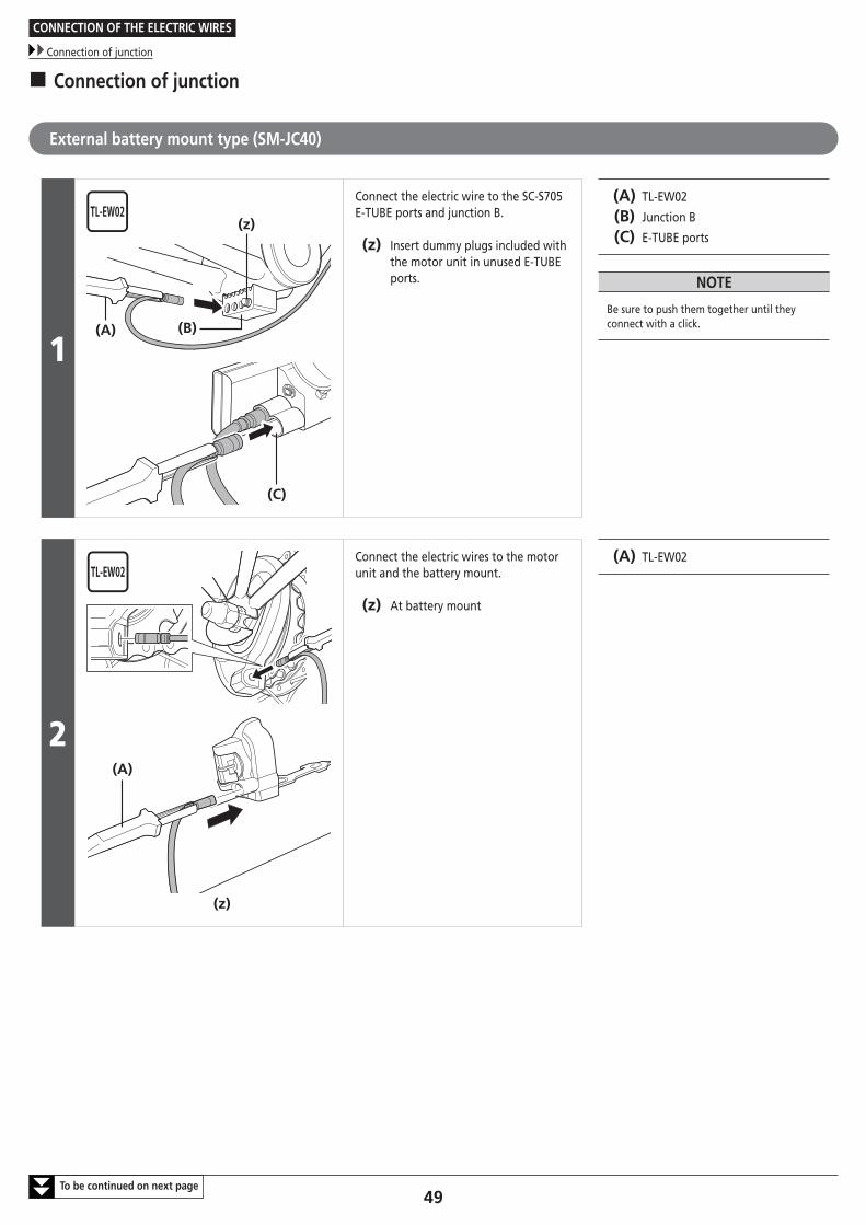
External battery mount type (SM-JC40)
1(B)(A)
(z)
(C)
Connect the electric wire to the SC-S705 E-TUBE ports and junction B.
(z) Insert dummy plugs included with the motor unit in unused E-TUBE ports.
(A) TL-EW02
(B) Junction B
(C) E-TUBE ports
NOTE
Be sure to push them together until they connect with a click.
2
(z)
(A)
Connect the electric wires to the motor unit and the battery mount.
(z) At battery mount
(A) TL-EW02

50To be continued on next page
CONNECTION OF THE ELECTRIC WIRES
Connection of junction
3
Temporarily secure the electric wire along the frame with tape, and connect it to junction B.
NOTE
When routing the electric wire to the motor unit, be sure to install it to the bottom of the chainstay to avoid any interference between the cable and the chain.
4
Wind any excess length of electric wire inside junction B to adjust the length.
Example of adjusting junction B length
5
(A) Once the electric wires have been routed, secure junction B underneath the bottom bracket shell.
(A) Junction B fixing bolt (10.5mm or 15mm)
Tightening torque
1.5 - 2 N·m

51
CONNECTION OF THE ELECTRIC WIRES
Connection of junction
6
Next, install the electric wire cover onto the frame.
In order to make sure that the electric wire cover is securely installed, clean the frame with alcohol or some other cleaning agent to remove any grease or other substances before installing the cover.
Place the electric wire cover over the electric wires, and then attach it to the frame.
7After connecting the electric wires to all of the components, install the battery and check the operation.
Check that gear-shifting of the rear can be performed properly by operating the shifting switch.

52
CONNECTION OF THE ELECTRIC WIRES
Connection of junction
Disconnection of the electric wires
NOTE
Do not keep connecting and disconnecting the small waterproof connector. The waterproof section or the connecting section may become worn or deformed, and the function may be affected.
1
MU-S705 Use the wide end of the TL-EW02 Shimano original tool to disconnect the electric wires.
NOTE
Use the wide end of the TL-EW02 Shimano original tool to disconnect the electric wires. If you pull too firmly on the connectors, problems with operation may occur. Insert the Shimano original tool so that the flat side is facing toward the derailleur, and then tilt it so as to pull out the connector of the electric wire.
2
When disconnecting the electric wire from a lever, face the flat side toward the lever.
When disconnecting the connector of junction, insert the Shimano original tool so that the flat side is facing toward junction.
(A) TL-EW02
ST-S705
(A)
SM-JC41
(A)
SM-JC40
(A)
SC-S705
(A)
3 Run any excess length of electric wire along the handlebar, and use zip tie or similar to secure the electric wire to the handlebar.

53To be continued on next page
CONNECTION OF THE ELECTRIC WIRES
Connection of junction
Built-in battery mount type (SM-JC41)
1
(D)
(B)
(C)
(A)
First, insert the electric wire for each of SC-S705, the battery mount, and the motor unit through the hole in the frame to the hanger section.
(A) Electric wire for motor unit
(B) Electric wire for built-in battery
(C) Electric wire for SC-S705
(D) Bottom bracket shell
NOTE
The electric wires have a correct way of being inserted.Make sure that you insert them from the direction shown in the illustration.
Wire holder
54
CONNECTION OF THE ELECTRIC WIRES
Connection of junction
2
(z)
(A)
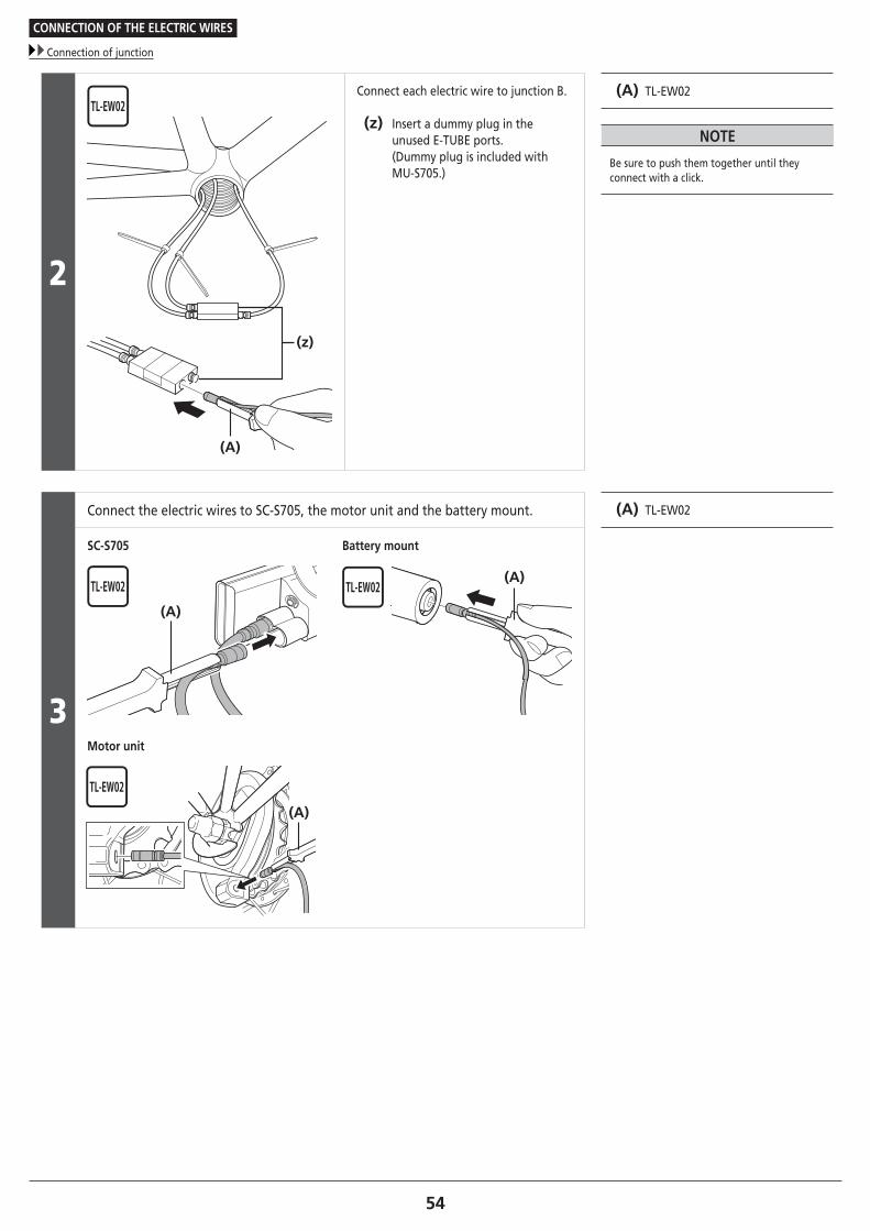
Connect each electric wire to junction B.
(z) Insert a dummy plug in the unused E-TUBE ports. (Dummy plug is included with MU-S705.)
(A) TL-EW02
NOTE
Be sure to push them together until they connect with a click.
3
Connect the electric wires to SC-S705, the motor unit and the battery mount. (A) TL-EW02
SC-S705
(A)
Battery mount
(A)
Motor unit
(A)

55
CONNECTION OF THE ELECTRIC WIRES
Connection of junction
Routing junction B and the electric wires inside the frame
1
Pass the electric wires for the motor unit and the built-in battery through the chainstay and the seat tube, respectively.
2(B)
(A)
Pass the electric wire for SC-S705 and junction B through the down tube.
Check that the screws of the bottom bracket shell do not damage any of the components at this time.
(A) Junction B
(B) For SC-S705
3
Make only the electric wires for the motor unit and the built-in battery visible inside the hanger; push unnecessary protruding components such as the wire holder into the frame.

56
CONNECTION OF THE ELECTRIC WIRES
Connection of junction
Assembly of the bottom bracket shell
1
(A) (B)
When installing the inner cover to the hanger, pass the electric wires for the motor unit and the built-in battery over the inner cover.
(A) Inner cover
(B) Adapter
2
(A)
(B)
Install the inner cover to the bottom bracket adapter.
(A) Inner cover
(B) Adapter
NOTE
If using a frame which does not have enough space between the inside of the bottom bracket shell and the inner cover to route the electric wires use an inner cover which is sold separately.

57
CONNECTION OF THE ELECTRIC WIRES
Connection of junction
Installation of grommets
Install grommets in appropriate positions for the electric wires by inserting the bottoms into the holes in the frame and then pushing the tops to fit them into place.
(y) Close
(z) Open
At SC-S705
(y) (z)
At motor unit

OPERATION

59
OPERATION
Displaying and operating the system information display (SC-MT800)
OPERATION
� Displaying and operating the system information display (SC-MT800)
Names of parts
(D)
(A) (B)
(C)
(A) Mode switch
(B) Terminal section
(C) Charging port
(D) Clamp band
Basic screen display
(C)
(A) (B) (A) Battery level
(B) Gear position/Adjustment level/ RD Protection Reset mode
(C) Operation mode
NOTE
RD Protection Reset mode can be selected, however, RD Protection Reset cannot be performed.The function is operable on rear derailleurs (DI2) only.For details on RD Protection, refer to the user’s manual of a supported model.

60
OPERATION
Displaying and operating the system information display (SC-MT800)
Battery level
(A) (A) Battery level
Display Battery level
81% – 100%
61% – 80%
41% – 60%
26% – 40%
1% – 25%
0%*
TECH TIPS
* When there is insufficient battery power, the motor unit will cease operating and gear positions will remain fixed at the last engaged positions. The battery indicator blinks for 2 seconds at the time of input operation. It is recommended to charge the battery as soon as possible.
Gear position/Adjustment level
(B) (B) Gear position/Adjustment level
Setting mode Details
Shift mode Gear position of the internal geared hub is displayed.
Adjustment mode When adjusting the motor unit, the adjustment level is displayed.
TECH TIPS
The display information varies depending on the mode setting.

61
OPERATION
Displaying and operating the system information display (SC-MT800)
Operation mode
(C)
(C) Operation mode
Display Details
Adjustment of the motor unitThe motor unit can be adjusted in this mode.Adjustment can be performed 4 increments in the + direction and 4 decrements in the – direction; a total adjustment range of 8 values.Adjustment values can be changed using the dual control lever or shifting switches.
Manual shiftGears are shifted manually in this mode.
CAUTION
• Improper adjustment may cause gear engagement skipping, resulting in an accidental fall.
• Perform adjustment only when you have an unusual feel during shifting. If there is no problem with shifting, unnecessary adjustment may worsen shifting performance.
How to operate
(x)
(z)
(y)Single click (2 seconds)
Single click (0.5 seconds)
Pressing and holding down (5 seconds or more)
(x) Shift mode
(y) Adjustment mode
(z) RD Protection Reset mode (RD Protection Reset cannot be used.)
NOTE
RD Protection Reset mode can be selected, however, RD Protection Reset cannot be performed.The function is operable on rear derailleurs (DI2) only.For details on RD Protection, refer to the user’s manual of a supported model.
62
OPERATION
Error message
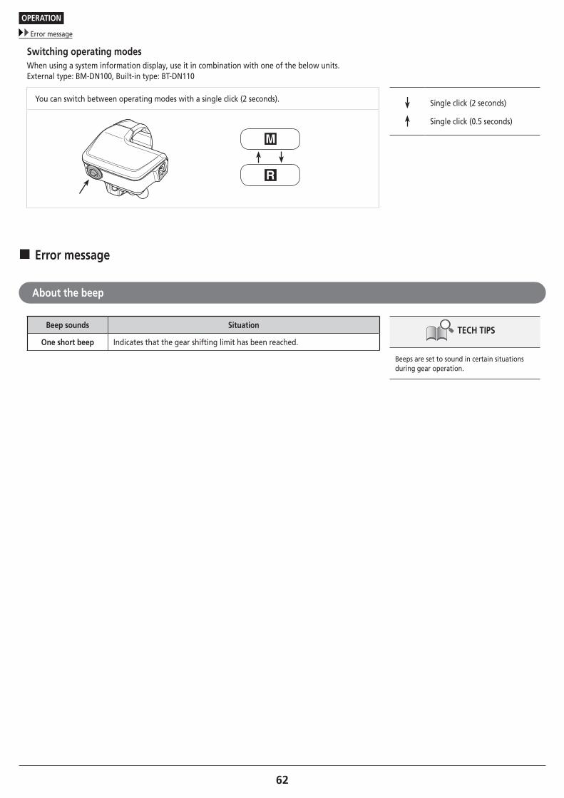
Switching operating modesWhen using a system information display, use it in combination with one of the below units.External type: BM-DN100, Built-in type: BT-DN110
You can switch between operating modes with a single click (2 seconds). Single click (2 seconds)
Single click (0.5 seconds)
� Error message
About the beep
Beep sounds Situation
One short beep Indicates that the gear shifting limit has been reached.TECH TIPS
Beeps are set to sound in certain situations during gear operation.

63To be continued on next page
OPERATION
About wireless functions (SC-MT800)
� About wireless functions (SC-MT800)
Functions
ANT connection
ANT connection facilitates the transmission of the following three types of information to compatible cycle computers or receivers.
(1) Gear position (rear)
(2) DI2 battery level information (External type: BM-DN100, Built-in type: BT-DN110)
(3) Adjustment mode information
For information on which of the above types of information are displayed, refer to the manual for your cycle computer or receiver.
TECH TIPS
The latest functions can be checked by updating the software via E-TUBE PROJECT. For details, consult the place of purchase.
Bluetooth® LE connectionE-TUBE PROJECT for smartphones/tablets may be used if a Bluetooth LE connection is established with a smartphone/tablet.
How to make connections
ANT connectionTo make a connection, the cycle computer needs to be in connection mode. For information on how to put the cycle computer into connection mode, refer to the manual for the cycle computer.
1 Put the cycle computer into connection mode.
2
When using an external batteryCheck that the electric wires are connected to the system information display, and then remove and remount the external battery.
When using a built-in batteryCheck that the electric wires are connected to the system information display, and then remove the electric wires from the system information display and reconnect them.
TECH TIPS
Connection transmission begins about 30 seconds after the battery is remounted or the electric wires are reconnected to the system information display.

64
OPERATION
About wireless functions (SC-MT800)
3
This completes the connection process. TECH TIPS
• Check on the cycle computer to see if connection was successful.
• If a connection cannot be made in the way described above, refer to the manual for your cycle computer.
• For information on how to show gear position or the DI2 battery level, refer to the manual for the cycle computer.
Bluetooth® LE connectionBefore setting up a connection, turn on Bluetooth LE on the smartphone/tablet.
1 Open E-TUBE PROJECT and set it to listen for Bluetooth LE signals.
2
Press the mode switch until "C" appears on the display.
The unit on the bicycle will begin signal transmission. The unit name displays in E-TUBE PROJECT.(Release the mode switch or button as soon as the unit on the bicycle begins signal transmission. If the mode switch or button is held down for any longer, a different mode will be activated.)
3
Select the unit name displayed on screen. TECH TIPS
To disconnect, cancel the Bluetooth LE connection from the smartphone/tablet. (The cycle computer will exit connection mode and return to regular operation mode.)

CHARGING THE BATTERY

66
CHARGING THE BATTERY
Names of parts
CHARGING THE BATTERY
Use the specified combination of lithium ion batteries, chargers, and linkage devices.Any other combinations may cause rupture or fire.Fully understand the precautions for use provided at the beginning of the dealer's manual before using the products.
� Names of parts
External type (SM-BCR1/SM-BTR1)
Battery charger (SM-BCR1)
(A)
(B)
(F)
(D)
(E)
(C)
(A) Electrical contacts: If these are modified or damaged, problems with operation will occur. Be very careful when handling them.
(B) ERROR indicator: This flashes when there is an error.
(C) CHARGE indicator: This illuminates while charging is in progress.
(D) Power cord connector
(E) Power cord: Insert into the connector. Insert all the way.
(F) Charger cord (Sold separately)
TECH TIPS
This is a special charger for charging Shimano lithium ion batteries (SM-BTR1).
Special battery (SM-BTR1)
(A)
(A) Electrical contacts: If these are modified or damaged, problems with operation will occur. Be very careful when handling them.
TECH TIPS
This is a lithium ion battery.Use the special charger (SM-BCR1) to charge it.

67
CHARGING THE BATTERY
Names of parts
Built-in type (SM-BCR2/SM-BTR2, BT-DN110)
USB cable
(A) (B)
(A) Micro USB plug: Connect to the battery charger.
(B) USB plug: Connect to a PC USB port or an AC adapter with a USB port.
Battery charger (SM-BCR2)
(A) (C) (D)(B)
(A) Micro USB connector
(B) CHARGE indicator
(C) ERROR indicator
(D) Plug for product connection: Connect to junction A or the charging connector of the system information display.
TECH TIPS
• This is a special charger for charging Shimano lithium ion batteries (SM-BTR2/BT-DN110).
• If water collects in the product connector, connect the plug only after wiping it off.
Special battery (SM-BTR2/BT-DN110)
TECH TIPS
This is a lithium ion battery.Use the special charger (SM-BCR2) to charge it.

68
CHARGING THE BATTERY
Charging the battery
� Charging the battery
External type (SM-BCR1/SM-BTR1)
1 Insert the power plug of the battery charger into an electrical outlet.
2
Insert the battery (SM-BTR1) into the battery charger (SM-BCR1) as far as it will go.
TECH TIPS
Charging takes up to approximately 1.5 hours. (Note that the actual time will vary depending on the remaining battery charge.)
3
(A)
When the CHARGE indicator (orange) switches off, charging is complete.
(A) CHARGE indicator
NOTE
If the ERROR indicator flashes, it means that there may be a problem with the battery.Refer to "When charging is not possible" for more information.
4 Disconnect the power plug of the battery charger from the electrical outlet and store the battery charger in a suitable place as specified in the Safety Precautions.

69
CHARGING THE BATTERY
Charging the battery
Built-in type (SM-BCR2/SM-BTR2, BT-DN110)
Example of connection for charging
The position of the charging port differs depending on the product. (z) To an AC adapter with a USB port or PC
(A) Charging port
(z)
(A)
(A)
1Connect the battery to junction A or the system information display. TECH TIPS
The battery can be charged by using an AC adapter with a USB port or connecting the charger to the USB connector of a PC.
2
Connect the charging cable of the battery charger to junction A or the charging port of the system information display.
TECH TIPS
The charging time of an AC adapter with a USB port is about 1.5 hours, and that of computer USB port type about 3 hours. (Note that the actual time will vary depending on the remaining battery charge.) Depending on the specifications of the AC adapter, recharging via the AC adapter may require as much time (about 3 hours) as recharging via PC.
3When the CHARGE indicator (orange) switches off, charging is complete. TECH TIPS
If ERROR indicator or CHARGE indicator blinks, refer to "When charging is not possible".
4 Disconnect the charging cable or USB cable, and keep it at the location specified in the precautions.

70
CHARGING THE BATTERY
When charging is not possible
� When charging is not possible
External type (SM-BCR1/SM-BTR1)
(z)
Remove the battery from the battery charger, disconnect the power plug of the battery charger from the electrical outlet, and then repeat the charging operation.
If charging is still not possible after the above steps have been carried out, the ambient temperature may be too low or too high, or there may be a problem with the battery.
(z) If charging is not possible, the ERROR indicator on the battery charger will flash.

71
CHARGING THE BATTERY
When charging is not possible
Built-in type (SM-BCR2/SM-BTR2, BT-DN110)
1 Make sure that only one unit of SM-BCR2 is connected to a PC.
2
If the ERROR indicator blinks
(A)
If the ERROR indicator blinks, the ambient temperature during charging may fall outside the operating temperature limits.
Check that the temperature is appropriate.
(A) ERROR indicator
If the CHARGE indicator blinks
(A)
If the CHARGE indicator blinks, refer to the following.
• The current capacity of your AC adapter with a USB port is lower than 1.0Adc. Use an AC adapter with a USB port
with a current capacity equal to or higher than 1.0Adc.
• A USB port is used to connect to the PC. Remove the USB hub.
(A) CHARGE indicator
3
If none of the above (1 to 2) is the case, the battery or junction may be faulty. NOTE
If the CHARGE indicator does not light up or goes out soon, the battery may be fully charged. Check the remaining power of the battery using junction A or the system information display.If the battery is low or dead, contact the place of purchase or a bicycle dealer.
If it becomes impossible to charge, the CHARGE indicator (orange) or ERROR indicator of the battery charger will blink.

CONNECTION AND COMMUNICATION WITH DEVICES

73
CONNECTION AND COMMUNICATION WITH DEVICES
Settings customizable in E-TUBE PROJECT
CONNECTION AND COMMUNICATION WITH DEVICES
Connecting the bicycle (system or components) to a device enables such operations as updating system firmware and customization.
You need E-TUBE PROJECT to configure the system and update firmware.
Download E-TUBE PROJECT from our support website (http://e-tubeproject.shimano.com).
For information on how to install E-TUBE PROJECT, check the support website.
TECH TIPS
You need SM-PCE1 and SM-JC40/JC41 to connect the system to a PC. They are not required if there is an available port.Firmware is subject to change without notice.
System requirements
PC linkage device E-TUBE PROJECT Firmware
SM-BMR2/
SM-BTR2 SM-PCE1/
SM-BCR2
Version 2.6.0 or later Version 3.0.0 or later
BT-DN110/
BM-DN100Version 3.0.0 or later
Version 4.0.0 or later* Pre-installed firmware is version 4.0.0.
NOTE
If your versions of E-TUBE PROJECT software and firmware for each component are not up to date there could be problems operating the bicycle. Check the versions and update them to the latest ones.
� Settings customizable in E-TUBE PROJECT
Display settings
Beep setting You can switch the beep between ON and OFF.
Display time Sets the time until the display turns off when the display monitor is left
unattended.
Switch setting Changes the function settings of the shifting switch and suspension switch.
Motor unit adjustment setting Adjusts motor unit-driven gear shifting.
Configure multi shift mode
settings
Multi-shift mode ON/OFF Select whether or not to use multi-shift.
Gear-shifting interval Sets the gear-shifting interval for multi-shift.
Gear number limit Sets the limit on the number of gears shifted when the shifting switch is held
down.

74
CONNECTION AND COMMUNICATION WITH DEVICES
Connecting to a PC
� Connecting to a PC
When using SC-MT800
Remove the dummy plug from the system information display, and connect SM-PCE1. (A) SM-PCE1
(B) Dummy plug
(B)
(A)

MAINTENANCE

76
MAINTENANCE
Battery level indicator
MAINTENANCE
� Battery level indicator
• When the battery level is low, the motor unit stops operating. When the battery is completely drained, the motor unit is fixed at the last gear position.
• When the battery indicator is at a level that requires charging, it is recommended that the battery be charged soon.
(y) Charging needed
(z) If the battery level is ZERO, not displayed on screen.
SC-S705
(y) (z)
0% 100% 0% 100%
SC-MT800
(y) (z)0% 100% 0% 100%
� System power reset
SM-BTR1
After the battery is removed, about one minute is usually required for the system power to reset.
SM-BTR2/BT-DN110
Disconnect the plug from SM-BTR2/BT-DN110. After about one minute, insert the plug.
� Troubleshooting
Symptoms Remedies
MU-S705System information display does not show the number
of the gears.Check if motor unit is connected.
SC-S705/SC-MT800The number of the gears on the system information
display does not change.Check if motor unit is connected.

77To be continued on next page
MAINTENANCE
Adjusting the motor unit (connection and communication with PC)
� Adjusting the motor unit (connection and communication with PC)
CAUTION
• Improper adjustment may cause gear engagement skipping, resulting in an accidental fall.
• Perform adjustment only when you have an unusual feel during shifting. If there is no problem with shifting, unnecessary adjustment may worsen shifting performance.
[A]
[B]
(y)
(z)
(y) Set the adjustment value
(z) Shift gears
TECH TIPS
This screen is shown in English, however, a total of 8 languages are available on E-TUBE PROJECT.(Japanese/English/German/French/Italian/Chinese/Dutch/Spanish)
1 Download the latest version of E-TUBE PROJECT from the support website.(http://e-tubeproject.shimano.com)
2Connect SM-PCE1 or SM-BCR2.
Connect the battery when connecting SM-BCR2.
3 Activate the adjustment setting mode in E-TUBE PROJECT.
4
Check that the adjustment value is set to 0 (default) in E-TUBE PROJECT [A].
(1) Value is set to 0 Go to step 5
(2)Value is set to other
than 0
Adjust the value to 0 and shift gears to check whether
abnormal noise or unusual feels have been eliminated.
At this time, shift gears via E-TUBE PROJECT [B].
The problem persists Go to step 5
The problem has been
remedied Go to step 6

78
MAINTENANCE
Adjusting the motor unit (connection and communication with PC)
5
Change the adjustment value by one in the + or - direction in E-TUBE PROJECT (Illustration [A] below), and check the sound or feel of gear shifting.* Adjustment can be performed 4 increments in the + direction and 4 decrements in the – direction; a total adjustment range of 8 values.
At this time, shift gears via E-TUBE PROJECT [B].
(1)The problem has
been remedied
Check the sound or feel of gear shifting again while changing the adjustment value one by one in the
same direction.
Continue adjusting the value until the abnormal noise or unusual feels are eliminated.
(2)No sign of
improvement
Change the adjustment value by one again in the same
direction and then check the sound or feel of gear
shifting again.
The problem has been
remedied
Go to
step5(1)
The problem persists Go to
step5(3)
(3)The condition has
worsened
Change the adjustment value by two in the opposite direction and then check the sound or feel of gear
shifting again.
Continue adjusting the value by one in the same direction until the abnormal noise or unusual feels are
eliminated.
6 Finally, ride the bicycle to check whether there is no problem.

79To be continued on next page
MAINTENANCE
Adjusting the motor unit (connection and communication with smartphone or tablet)
� Adjusting the motor unit
(connection and communication with smartphone or tablet)
CAUTION
• Improper adjustment may cause gear engagement skipping, resulting in an accidental fall.
• Perform adjustment only when you have an unusual feel during shifting. If there is no problem with shifting, unnecessary adjustment may worsen shifting performance.
(z)[B]
(y)[A]
(y) Set the adjustment value
(z) Shift gears
TECH TIPS
This screen is shown in English, however, a total of 8 languages are available on E-TUBE PROJECT.(Japanese/English/German/French/Italian/Chinese/Dutch/Spanish)
1 Download E-TUBE PROJECT for smartphones/tablets.
2 Establish a Bluetooth LE connection with a smartphone or tablet referring to the section "About wireless functions (SC-MT800)".
3 Activate the adjustment setting mode in E-TUBE PROJECT.
4
Check that the adjustment value is set to 0 (default) in E-TUBE PROJECT [A].
(1) Value is set to 0 Go to step 5
(2)Value is set to other
than 0
Adjust the value to 0 and shift gears to check whether
abnormal noise or unusual feels have been eliminated.
At this time, shift gears via E-TUBE PROJECT [B].
The problem persists Go to step 5
The problem has been
remedied Go to step 6

80
MAINTENANCE
Adjusting the motor unit (connection and communication with smartphone or tablet)
5
Change the adjustment value by one in the + or - direction in E-TUBE PROJECT (Illustration [A] below), and check the sound or feel of gear shifting.* Adjustment can be performed 4 increments in the + direction and 4 decrements in the – direction; a total adjustment range of 8 values.
At this time, shift gears via E-TUBE PROJECT [B].
(1)The problem has
been remedied
Check the sound or feel of gear shifting again while changing the adjustment value one by one in the
same direction.
Continue adjusting the value until the abnormal noise or unusual feels are eliminated.
(2)No sign of
improvement
Change the adjustment value by one again in the same
direction and then check the sound or feel of gear
shifting again.
The problem has been
remedied
Go to
step5(1)
The problem persists Go to
step5(3)
(3)The condition has
worsened
Change the adjustment value by two in the opposite direction and then check the sound or feel of gear
shifting again.
Continue adjusting the value by one in the same direction until the abnormal noise or unusual feels are
eliminated.
6 Finally, ride the bicycle to check whether there is no problem.

81To be continued on next page
MAINTENANCE
Disassembling the bracket body and lever body
� Disassembling the bracket body and lever body
1
(z)
(A) [1]
[2]
Use the Shimano original tool which is sold separately to remove the E-ring.
Align section [2] of the Shimano original tool with the removal direction of the E-ring. Next, set section [1] against the E-ring and remove the E-ring.
(z) E-ring removal direction
(A) Special E-ring removal tool Y6RT68000
NOTE
When you remove the E-ring, it may pop out; wear protective glasses while removing it. Check that there is no one or no object around you before starting the work.
2
(A)
(B)
Insert a hexagon wrench or a similar tool into the hole in the lever axle, and then tap it with a plastic mallet to push out the lever axle.
(A) Hexagon wrench
(B) Lever axle
3
(A) Remove the return spring. (A) Return spring

82To be continued on next page
MAINTENANCE
Assembly of the switch unit
4
After removing the two switch unit fixing screws, the switches and the switch springs, it can be disassembled into the bracket body and the lever body.
(A) Switch unit fixing screw (Hexalobular[#5])
(A)
� Assembly of the switch unit
1(A)
(z)
Check that the buttons are attached to the springs, then insert the switch springs into the holes in the switch unit setting plate.
(z) Applying grease Premium grease (Y-04110000)
(A) Switch spring
2
Place the switch unit onto the mounting surface of the setting plate.

83
MAINTENANCE
Assembly of the switch unit
3
(A)
(B)
Press the switch unit by hand so that the switch springs go into the grooves in the buttons, and then push the shifting switches [X/Y] in as far as they will go.
(A) Switch unit
(B) Shifting switches [X/Y]
4
Make a gap between the switch unit and the setting plate and check that the end of the rubber on the switch unit is on the button.
5
Return the switch unit to the setting position for the switch unit setting plate, and while pressing it by hand, operate the shifting switches [X/Y] once more and check that the switches turn on.
Install the switch using the switch unit fixing screws.
Tightening torque
0.18 N·m

84
MAINTENANCE
Assembly of the bracket body and lever body
� Assembly of the bracket body and lever body
1(A)
Assemble the bracket body and the lever body, and then attach the return spring.
(A) Return spring
2
(A)
Align with the hole in the axle, and then press-fit the lever axle.
(A) E-ring groove
TECH TIPS
• The correct direction for the lever axle is for the E-ring groove to face up.
• Check that the surface of the bracket body and the top end of the lever axle are flush with each other so that the E-ring will fit into the groove.
3(A)
[1]
Use section [1] of the Shimano original tool to install the E-ring.
(A) Special E-ring removal tool Y6RT68000
TECH TIPS
Operate the shifting switches [X/Y] and check that they turn on, and check that the lever operates smoothly.

85To be continued on next page
MAINTENANCE
In the case of 8-speed internal geared hub (Oil maintenance kit: Y00298010)
� In the case of 8-speed internal geared hub (Oil maintenance kit: Y00298010)
(A)
To maintain the product in good working order, it is recommended to have a bicycle dealer or nearest agency carry out maintenance such as lubrication of the internal parts about once every two years from the first time of use (once about every 5,000km if the bicycle is used very frequently).
Also, for carrying out maintenance, the use of Shimano internal geared hub grease or a lubrication kit is recommended.
If Shimano grease or a Shimano lubrication kit is not used, problems such as a malfunction in gear shifting may occur.
(A) WB maintenance oil set (Y00298010)
1(z)
Fill the container with maintenance oil to a height of 95mm.
(z) 95mm
2
(z)Immerse the internal unit in the oil from the left side until the oil reaches up to ring gear unit 1, as shown in the illustration.
(z) Ring gear unit 1
3
Keep the internal unit immersed for approximately 90 seconds.
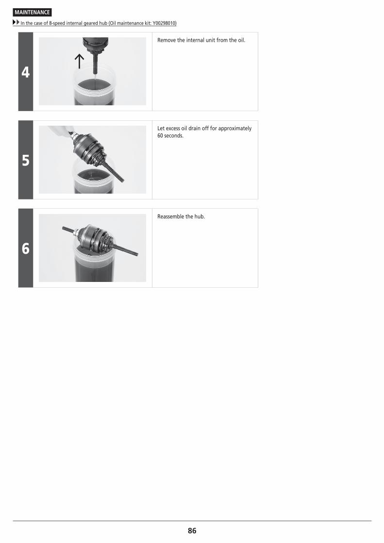
86
MAINTENANCE
In the case of 8-speed internal geared hub (Oil maintenance kit: Y00298010)
4
Remove the internal unit from the oil.
5
Let excess oil drain off for approximately 60 seconds.
6
Reassemble the hub.

87
MAINTENANCE
In the case of 11-speed internal geared hub (Oil maintenance kit: Y13098023)
� In the case of 11-speed internal geared hub (Oil maintenance kit: Y13098023)
Tools included in the kit: Syringe, Tube, Bleed nipple, O ring, Container
General Safety Information
WARNING
• When changing the oil, be careful that no oil gets on the disc brake rotor, brake pads, on the rim when using rim brakes, etc. If oil gets on any of these parts, there is a danger that brake performance may be reduced. Take care of this problem according to the procedures in the brake instruction manual.
• Since there is a risk of explosion or fire, do not smoke, eat, or drink while using this oil. In addition, keep it away from ignition sources such as heat, sparks, open flames, or high temperatures and prevent it from catching fire due to static electricity sparks or other sparks.
• Use only outdoors or in a well-ventilated area. Inhalation of oil mist or vapors may cause nausea. Be careful to provide ventilation and use a respirator-type mask. If mist or vapor is inhaled by mistake, go immediately to an area with fresh air, stay warm and quiet, and seek professional medical advice if required. If breathing stops, perform artificial respiration, and if breathing is difficult, provide the affected person with oxygen.
Cautions regarding handling of SG-S700 OIL : • Contact with eyes may result in irritation. Use safety glasses when handling, and avoid contact with eyes. In the event of eye contact, flush with fresh water and seek medical assistance immediately.
• Contact with skin may cause a rash and discomfort. Use gloves when handling. In the event of skin contact, wash well with soap and water. If skin condition becomes abnormal, seek medical assistance immediately.
• Do not drink. If it is drunk by mistake, do not induce vomiting; make the affected person drink 1 to 2 cups of water and seek medical assistance immediately. If the affected person loses consciousness, do not give the person anything by their mouth. If vomiting occurs naturally, tilt the body to prevent inhalation.
• After use, be sure to wash hands thoroughly.
• When storing, close the container tightly to prevent water or foreign materials from entering; store out of reach of children; do not store in areas subject to direct sunlight, areas subject to temperatures above 40°C, areas subject to water or high humidity where rust is likely to occur, or in areas where there is a risk of freezing.
• Dispose of used oil, old oil, or oil used for cleaning in accordance with applicable local laws and regulations.
• To maintain product performance, oil should be changed after the first 1,000 km from start of use of the product, and once every 2 years thereafter (after every 5,000 km if bicycle is ridden frequently).
• When performing maintenance, use only Shimano SG-S700 OIL. If SG-S700 OIL is not used, problems such as an oil leakage and gear shifting malfunction may occur.
• When using a 1L can of oil, it may become impossible to suck out oil with a syringe when there is only a little oil left. First, transfer all oil to a different container.
• Read these instructions carefully, and keep them in a safe place for later reference.

88To be continued on next page
MAINTENANCE
In the case of 11-speed internal geared hub (Oil maintenance kit: Y13098023)
Internal geared hub: Oil replacement
Using a stand, etc., enable the rear wheel to turn while performing work.
Draining out the old oil
1
(A)Rotate the wheel slowly until the oil port is facing up.
(A) Oil port
2
(A)
(B)
(C)
Remove the oil port bolt and O-ring. (A) 3mm hexagon wrench
(B) Oil port bolt
(C) O-ring
NOTE
Be careful that the oil port is facing up; if the oil port bolt is loosened when it is not facing up, the oil inside may leak out.

89To be continued on next page
MAINTENANCE
In the case of 11-speed internal geared hub (Oil maintenance kit: Y13098023)
3
(A) (B)
(C) (D)
Attach the bleed nipple with tube attached to the hub shell.
(A) Hub shell
(B) Tube
(C) 10mm spanner
(D) Bleed nipple
Tightening torque
1 - 3 N·m
TECH TIPS
Check that the O-ring is properly installed on the bleed nipple.
4
(A)
(B)
With the piston of the syringe pushed fully in, firmly connect the syringe to the tube.
(A) Tube
(B) Syringe
5
(z)
Insert the syringe between the spokes, and slowly turn the wheel forward until the oil port is facing down.
(z) Turn in forward direction
6 Wait about 5 minutes with the hub kept still and not turning so that the oil settles.

90
MAINTENANCE
In the case of 11-speed internal geared hub (Oil maintenance kit: Y13098023)
7 (A)
Pull the piston out slowly to draw out the oil inside the hub shell.
(A) Piston
NOTE
If the piston is pulled out quickly, air is likely to be mixed in.
8
Rotate the wheel slowly until the oil port is facing up.
NOTE
To make sure that the syringe does not get caught by the chain case, etc., store the syringe between the spokes when turning the wheel.
9(A)
(B)
While being careful that the tube does not come off the syringe, remove the bleed nipple.
(A) Bleed nipple
(B) 10mm spanner
10
Remove the old oil from the syringe.

91To be continued on next page
MAINTENANCE
In the case of 11-speed internal geared hub (Oil maintenance kit: Y13098023)
Cleaning the inside
1Attach the bleed nipple to the hub shell. Tightening torque
1 - 3 N·m
2
Suck 25ml of new oil into the syringe and connect it firmly to the tube. TECH TIPS
If the syringe or tube becomes dirty when removing old oil or cleaning the inside of the hub, clean the syringe and tube using parts cleaner, etc., if necessary.
3(A)
Push the piston to inject the new oil into the inside of the hub.
(A) Piston
TECH TIPS
When the oil is forced in, the internal pressure will increase and the piston may push back. If the piston is periodically pulled back to reduce the pressure inside the hub, the oil will be easier to inject into the inside of the hub.
4
After pulling back the piston to reduce the internal pressure, remove the bleed nipple. TECH TIPS
If the bleed nipple is removed without pulling back the piston, the oil may flow back into the piston together with air from inside the tube and spill out of the piston.
5
(A)
(B)(C)
Install the O-ring and the oil port bolt. (A) 3mm hexagon wrench
(B) Oil port bolt
(C) O-ring
Tightening torque
2 - 3 N·m

92
MAINTENANCE
In the case of 11-speed internal geared hub (Oil maintenance kit: Y13098023)
6 While performing gear-change operations, turn the pedals to turn the wheel for about 1 minute.
7 Keep the wheel still without rotating for about 1 minute.
8 Remove the oil from inside by following the procedures in Draining out the old oil above.
Injecting new oil
1 Inject 25ml of new oil into the hub by following steps Cleaning the inside 1 - 5 above.
2 Clean off any oil that may have gotten on the hub, etc.

Please note: specifications are subject to change for improvement without notice. (English) © Dec. 2016 by Shimano Inc. HTR