Embed Size (px)
Citation preview

(English) DM-WH0002-11
Dealer's Manual
ROAD MTB Trekking
City Touring/Comfort Bike
URBAN SPORT E-BIKE
ROAD wheel set
DURA-ACEWH-R9100-C24-CLWH-9000
ULTEGRAWH-6800
Non-SeriesWH-RS81WH-RS61WH-RS31WH-RS21WH-RS11WH-RS010WH-RS610WH-RS330WH-RS700WH-RS500WH-RS300WH-RS100
2
CONTENTS
IMPORTANT NOTICE .............................................................................................. 3
TO ENSURE SAFETY ............................................................................................... 4
LIST OF TOOLS TO BE USED .................................................................................. 8
INSTALLATION ..................................................................................................... 10Tire size .......................................................................................................................................................10
Cassette sprockets ......................................................................................................................................11
Brake shoe setting position .......................................................................................................................12
MAINTENANCE .................................................................................................... 14Spoke lacing ...............................................................................................................................................14
Replacing the spoke ...................................................................................................................................17
Replacement of the freewheel body ........................................................................................................45
Installing and removing tubeless tires ......................................................................................................61
Cautions on the use of tubular wheel rim ................................................................................................64
3
IMPORTANT NOTICE
IMPORTANT NOTICE
• This dealer's manual is intended primarily for use by professional bicycle mechanics. Users who are not professionally trained for bicycle assembly should not attempt to install the components themselves using the dealer's manuals. If any part of the information on the manual is unclear to you, do not proceed with the installation. Instead, contact your place of purchase or a local bicycle dealer for their assistance.
• Make sure to read all instruction manuals included with the product.
• Do not disassemble or modify the product other than as stated in the information contained in this dealer's manual.
• All dealer’s manuals and instruction manuals can be viewed on-line on our website (http://si.shimano.com).
• Please observe the appropriate rules and regulations of the country, state or region in which you conduct your business as a dealer.
For safety, be sure to read this dealer's manual thoroughly before use, and follow it for correct use.
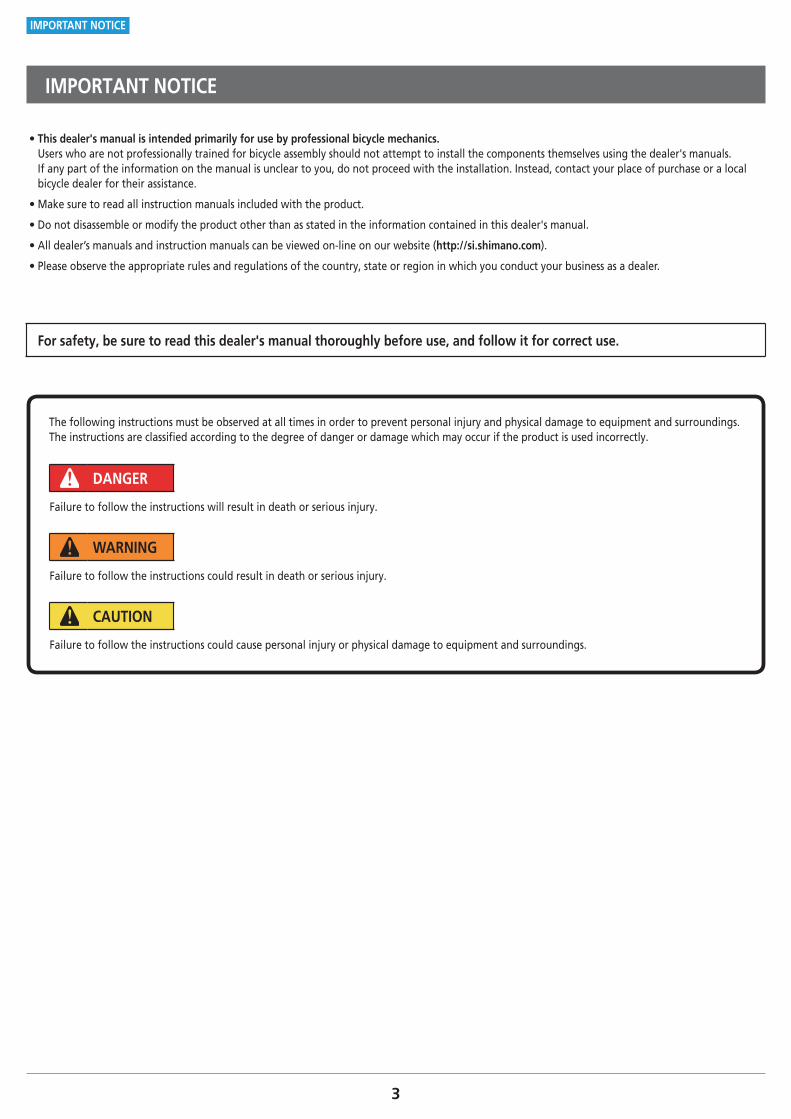
The following instructions must be observed at all times in order to prevent personal injury and physical damage to equipment and surroundings.The instructions are classified according to the degree of danger or damage which may occur if the product is used incorrectly.
DANGER
Failure to follow the instructions will result in death or serious injury.
WARNING
Failure to follow the instructions could result in death or serious injury.
CAUTION
Failure to follow the instructions could cause personal injury or physical damage to equipment and surroundings.
4
TO ENSURE SAFETY
TO ENSURE SAFETY
WARNING
• When installing components, be sure to follow the instructions that are given in the instruction manuals. It is recommended to use genuine Shimano parts only. If parts such as bolts and nuts become loose or damaged, the bicycle may suddenly fall over, which may cause serious injury. In addition, if adjustments are not carried out correctly, problems may occur, and the bicycle may suddenly fall over, which may cause serious injury.
• Be sure to wear safety glasses or goggles to protect your eyes while performing maintenance tasks such as replacing parts.
• After reading the dealer's manual thoroughly, keep it in a safe place for later reference.
Be sure to also inform users of the following: • Before use, check the wheels to make sure that there are no bent or loose spokes, dents, scratches or cracks on the rim surface. Do not use the wheel if any of these problems are found. The wheel may break, and you may fall. In the case of carbon wheels, check also that there is no carbon peeling or cracking.
• The tires should be inflated to the pressure indicated on the tires or rim before use. If the maximum pressure is prescribed on the tires and rim, be sure not to exceed the lower value shown.
• If the quick release mechanism is not used correctly, the wheel may come off the bicycle and serious injury could result. Read the Service Instructions for the quick release mechanism thoroughly before use.
• If the wheels are used in harsh conditions such as on unpaved surfaces, they may become bent or damaged, which may then result in accidents.
• Check that the wheels are fastened securely before riding the bicycle. If the wheels are loose in any way, they may come off the bicycle and serious injury may result.
< Clincher wheel / Tubeless wheel > • The hollow on the opposite side to the valve hole is an indicator for the amount of rim wear. If this hollow can no longer be seen, stop using the rim. If you continue using the rim, it may break, and the bicycle may fall over and an accident may result.
<Tubeless wheel> • The tires should be installed and removed by hand. If this is difficult, a plastic tire lever for tubeless wheels may be used. In such cases, be sure to check that the rim surface has not been dented, scratched, or cracked as there is a risk of causing damage to the air seal between the tire and the rim, which would result in air leakage. For carbon rims, check that there is no carbon peeling or cracking etc. Finally, make sure there is no air leakage.
• WH-RS700-TL: Maximum pressure = 8 bar / 116 psi / 800 kPa A higher pressure than indicated can cause a sudden puncture and / or sudden release of the tire, which can result in serious injury.
< Tubular wheel > • Before riding, check that the tires are securely glued to the rims. If the tires come off while riding, you may fall and get severely injured.
• If the braking surfaces of the carbon fiber rims become extremely worn and the rims appear to have become deformed, stop riding the bicycle. If you continue to ride the bicycle in this condition, it may fall over and serious injury may occur as a result.
For Installation to the Bicycle, and Maintenance: • Do not use in combination with bottom link-type suspension forks. With these types of forks, when the brakes are applied, the clearance between the hub axle and the brake shoes can change due to the operation of the suspension and the brake shoes may touch the spokes.
5
TO ENSURE SAFETY
CAUTION
Be sure to also inform users of the following: • When using a puncture repair agent, consult a dealer or an agency.
< C50/C75 wheel > • Note that a higher rim is more affected by side winds and makes riding unstable.
< Clincher wheel > • Use a high-pressure-resistant rim tape for the rim. Otherwise, a sudden puncture may occur, and you may fall off the bicycle.
• When you replace the rim tape, use the one that matches the rim size. If you use a rim tape that does not match the rim size, a sudden puncture may occur, and you may fall off the bicycle.
< Tubeless wheel > • Do not use rim tape. Rim tape may make it difficult to remove and install the tire, and the tire or tube may become damaged or the tires may suddenly puncture and come off, and severe injury may result.
• Do not use rim tape if using an inner tube. Rim tape may make it difficult to remove and install the tire, and the tire or tube may become damaged or the tires may suddenly puncture, causing the bicycle to fall over.
• If you use a tire such as a Tubeless Ready tire that needs to be used with a sealant, use the sealant recommended by the tire manufacturer.
�WH-RS700-TL • Be sure to use tubeless tape when using these wheels.
• It is recommended to use genuine Shimano tubeless tape to prevent punctures and other possible damage.
• When replacing the spokes, do not remove or attach the stainless steel tape directly by hand. Instead, always use the Shimano original tool included with the replacement stainless steel tape (service part). The edges of the stainless steel tape could injure your fingers.
< Tubular wheel > • Carbon fiber rims become worn due to friction from the brake shoes, and there may be a "run-in" period before the full performance of the rims can be obtained. As the run-in period progresses, the braking force will become stronger. Take this increase in braking force into account for safety purposes.
NOTE
Be sure to also inform users of the following: • Before use, check that there are no pieces of metal or other foreign objects sticking to the brake pads. If any such items are present, they may cause damage to the rim when the brakes are applied.
• Do not lubricate the internal parts of the hub. Otherwise, grease will flow out.
• It is recommended that you ask a bicycle dealer to adjust the spoke tensions if there is any deviation in the spokes and after the first 1,000 km of riding.
• Optional reflector and spoke protector sets are available. Check the model number on the website specifications and please ask your bicycle dealer for details.
• Products are not guaranteed against natural wear and deterioration from normal use and aging.
• For maximum performance we highly recommend Shimano lubricants and maintenance products.
< Clincher wheel / Tubeless wheel > • The Shimano R55HC (high performance) brake shoes use an aggressive compound designed with an emphasis on maximum performance in wet conditions, however they will cause accelerated rim wear. Shimano accepts no responsibility for reduced rim life which might occur from using R55HC brake shoes.
6
TO ENSURE SAFETY
< Tubular wheel > • For tubular specifications, use brake shoes for carbon rims such as R55C3 and R55C4. If you use any brake shoes other than those for carbon rims, they may provide insufficient braking force or wear quickly.
• Do not use an R55C3, R55C4 carbon rim brake shoe if it has been used with an aluminum rim. Using the shoe on an aluminum rim will cause aluminum wear powder to be stuck on the brake shoe, which will damage the brake friction surface of the carbon rim.
For Installation to the Bicycle, and Maintenance: • Be careful not to overtighten the nipples when adjusting the spoke tensions. If the nipples are overtightened, damage to the rim may result.
• If the wheel becomes stiff and difficult to turn, lubricate it with grease.
• Special nipple wrenches are available as optional accessories.
• For compatible reflectors and spoke protectors, check the specifications table (http://si.shimano.com).
< Clincher wheel / Tubular wheel > • Use of genuine Shimano spokes and nipples is strongly recommended. Otherwise, the area where the spokes fit into the hub body may become damaged.
< Tubeless wheel > • Use genuine Shimano spokes, nuts, spoke plugs and washers. Otherwise, the area where the spokes fit into the hub body may become damaged.
The actual product may differ from the illustration because this manual is intended mainly to explain the procedures for using the product.
LIST OF TOOLS TO BE USED
8
LIST OF TOOLS TO BE USED
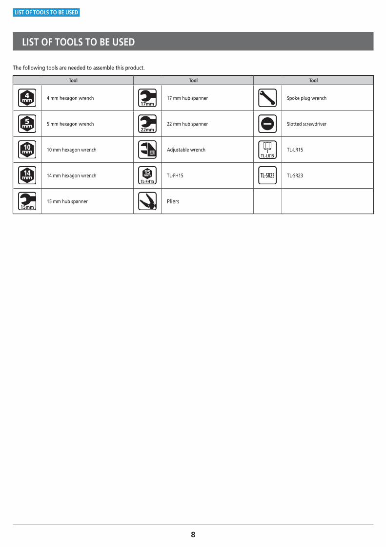
LIST OF TOOLS TO BE USED
The following tools are needed to assemble this product.
Tool Tool Tool
4 mm hexagon wrench 17 mm hub spanner Spoke plug wrench
5 mm hexagon wrench 22 mm hub spanner Slotted screwdriver
10 mm hexagon wrench Adjustable wrench TL-LR15
14 mm hexagon wrench TL-FH15 TL-SR23
15 mm hub spanner Pliers
INSTALLATION
10
INSTALLATION
Tire size
INSTALLATION
� Tire size
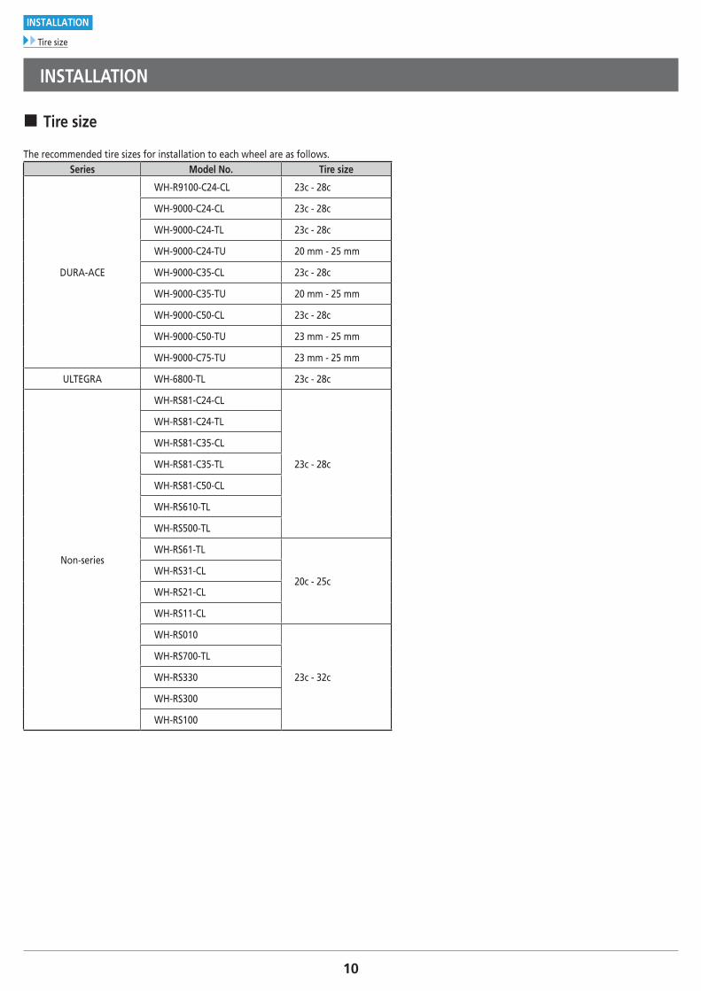
The recommended tire sizes for installation to each wheel are as follows.Series Model No. Tire size
DURA-ACE
WH-R9100-C24-CL 23c - 28c
WH-9000-C24-CL 23c - 28c
WH-9000-C24-TL 23c - 28c
WH-9000-C24-TU 20 mm - 25 mm
WH-9000-C35-CL 23c - 28c
WH-9000-C35-TU 20 mm - 25 mm
WH-9000-C50-CL 23c - 28c
WH-9000-C50-TU 23 mm - 25 mm
WH-9000-C75-TU 23 mm - 25 mm
ULTEGRA WH-6800-TL 23c - 28c
Non-series
WH-RS81-C24-CL
23c - 28c
WH-RS81-C24-TL
WH-RS81-C35-CL
WH-RS81-C35-TL
WH-RS81-C50-CL
WH-RS610-TL
WH-RS500-TL
WH-RS61-TL
20c - 25cWH-RS31-CL
WH-RS21-CL
WH-RS11-CL
WH-RS010
23c - 32c
WH-RS700-TL
WH-RS330
WH-RS300
WH-RS100
11
INSTALLATION
Cassette sprockets
� Cassette sprockets
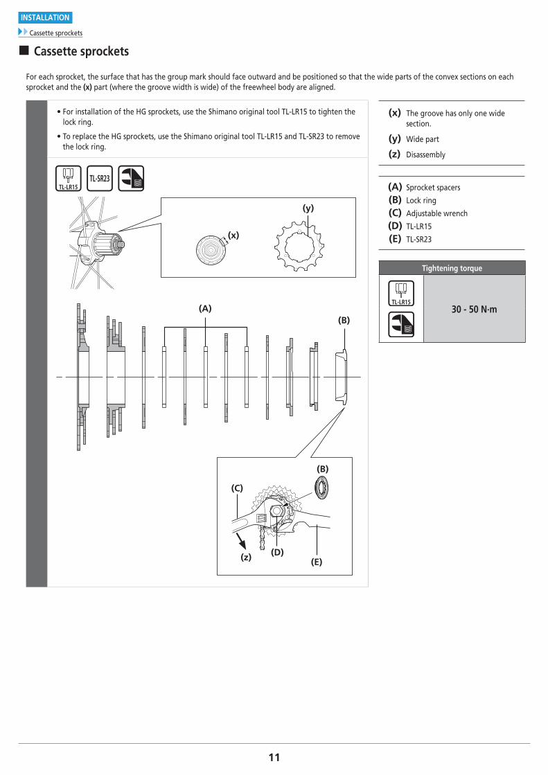
For each sprocket, the surface that has the group mark should face outward and be positioned so that the wide parts of the convex sections on each sprocket and the (x) part (where the groove width is wide) of the freewheel body are aligned.
• For installation of the HG sprockets, use the Shimano original tool TL-LR15 to tighten the lock ring.
• To replace the HG sprockets, use the Shimano original tool TL-LR15 and TL-SR23 to remove the lock ring.
(x) The groove has only one wide section.
(y) Wide part
(z) Disassembly
(A) Sprocket spacers
(B) Lock ring
(C) Adjustable wrench
(D) TL-LR15
(E) TL-SR23
Tightening torque
30 - 50 N·m
(y)
(x)
(z) (E)
(B)
(D)
(A)(B)
(C)
12
INSTALLATION
Brake shoe setting position
NOTE
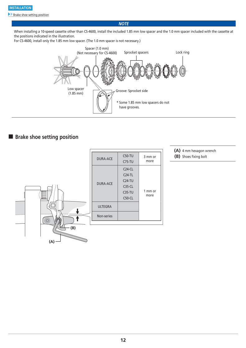
When installing a 10-speed cassette other than CS-4600, install the included 1.85 mm low spacer and the 1.0 mm spacer included with the cassette at the positions indicated in the illustration. For CS-4600, install only the 1.85 mm low spacer. (The 1.0 mm spacer is not necessary.)
Sprocket spacers Lock ringSpacer (1.0 mm)
(Not necessary for CS-4600)
Low spacer(1.85 mm)
Groove: Sprocket side
* Some 1.85 mm low spacers do not have grooves.
� Brake shoe setting position
DURA-ACEC50-TU
C75-TU3 mm or
more
DURA-ACE
C24-CL
C24-TL
C24-TU
C35-CL
C35-TU
C50-CL
1 mm or more
ULTEGRA
Non-series
(B)
(A)
(A) 4 mm hexagon wrench
(B) Shoes fi xing bolt
MAINTENANCE
14
MAINTENANCE
Spoke lacing
MAINTENANCE
� Spoke lacing
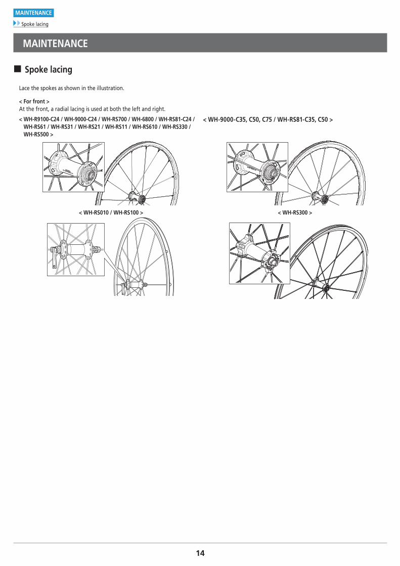
Lace the spokes as shown in the illustration.
< For front >At the front, a radial lacing is used at both the left and right.
< WH-R9100-C24 / WH-9000-C24 / WH-RS700 / WH-6800 / WH-RS81-C24 / WH-RS61 / WH-RS31 / WH-RS21 / WH-RS11 / WH-RS610 / WH-RS330 / WH-RS500 >
< WH-9000-C35, C50, C75 / WH-RS81-C35, C50 >
< WH-RS010 / WH-RS100 > < WH-RS300 >
15
MAINTENANCE
Spoke lacing
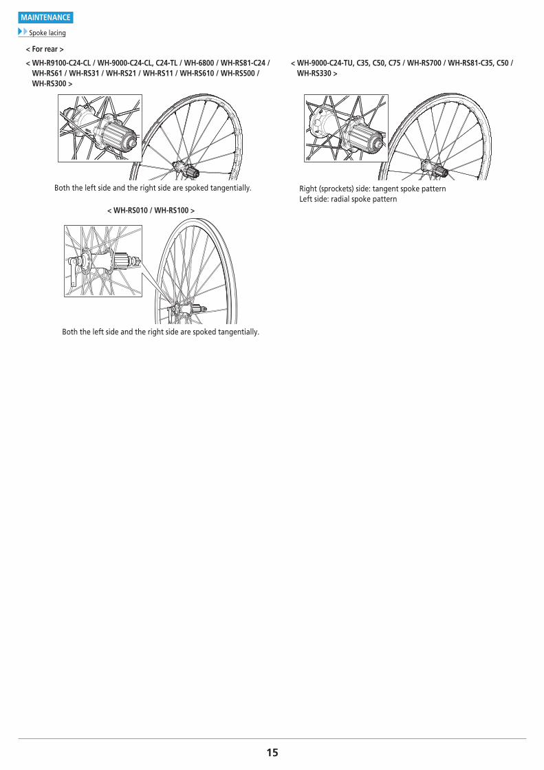
< For rear >
< WH-R9100-C24-CL / WH-9000-C24-CL, C24-TL / WH-6800 / WH-RS81-C24 / WH-RS61 / WH-RS31 / WH-RS21 / WH-RS11 / WH-RS610 / WH-RS500 / WH-RS300 >
< WH-9000-C24-TU, C35, C50, C75 / WH-RS700 / WH-RS81-C35, C50 / WH-RS330 >
Both the left side and the right side are spoked tangentially. Right (sprockets) side: tangent spoke pattern Left side: radial spoke pattern
< WH-RS010 / WH-RS100 >
Both the left side and the right side are spoked tangentially.
16
MAINTENANCE
Spoke lacing
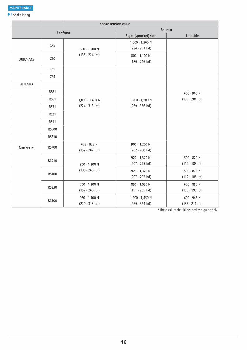
Spoke tension value
For frontFor rear
Right (sprocket) side Left side
DURA-ACE
C75600 - 1,000 N
(135 - 224 lbf)
1,000 - 1,300 N
(224 - 291 lbf)
600 - 900 N
(135 - 201 lbf)
C50800 - 1,100 N
(180 - 246 lbf)
C35
1,000 - 1,400 N
(224 - 313 lbf)
1,200 - 1,500 N
(269 - 336 lbf)
C24
ULTEGRA
Non-series
RS81
RS61
RS31
RS21
RS11
RS500
RS610
RS700675 - 925 N
(152 - 207 lbf)
900 - 1,200 N
(202 - 268 lbf)
RS010800 - 1,200 N
(180 - 268 lbf)
920 - 1,320 N
(207 - 295 lbf)
500 - 820 N
(112 - 183 lbf)
RS100921 - 1,320 N
(207 - 295 lbf)
500 - 828 N
(112 - 185 lbf)
RS330700 - 1,200 N
(157 - 268 lbf)
850 - 1,050 N
(191 - 235 lbf)
600 - 850 N
(135 - 190 lbf)
RS300980 - 1,400 N
(220 - 313 lbf)
1,200 - 1,450 N
(269 - 324 lbf)
600 - 943 N
(135 - 211 lbf)
* These values should be used as a guide only.
17To be continued on next page
MAINTENANCE
Replacing the spoke
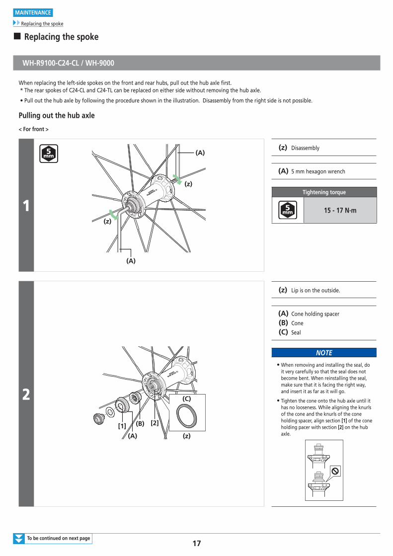
� Replacing the spoke
WH-R9100-C24-CL / WH-9000
When replacing the left-side spokes on the front and rear hubs, pull out the hub axle first.* The rear spokes of C24-CL and C24-TL can be replaced on either side without removing the hub axle.
• Pull out the hub axle by following the procedure shown in the illustration. Disassembly from the right side is not possible.
Pulling out the hub axle
< For front >
1
(z)
(z)
(A)
(A)(z) Disassembly
(A) 5 mm hexagon wrench
Tightening torque
15 - 17 N·m
2
(B)
(A)
(C)
(z)
[1] [2]
(z) Lip is on the outside.
(A) Cone holding spacer
(B) Cone
(C) Seal
NOTE
• When removing and installing the seal, do it very carefully so that the seal does not become bent. When reinstalling the seal, make sure that it is facing the right way, and insert it as far as it will go.
• Tighten the cone onto the hub axle until it has no looseness. While aligning the knurls of the cone and the knurls of the cone holding spacer, align section [1] of the cone holding pacer with section [2] on the hub axle.
18To be continued on next page
MAINTENANCE
Replacing the spoke
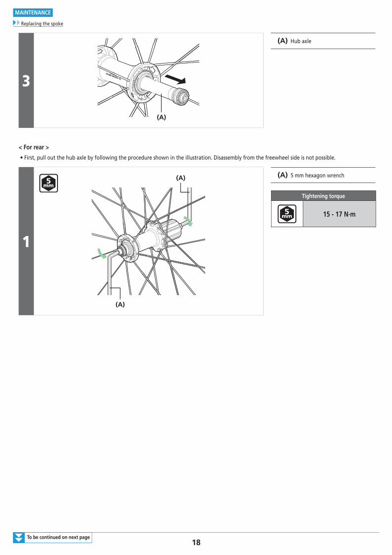
3
(A)
(A) Hub axle
< For rear >
• First, pull out the hub axle by following the procedure shown in the illustration. Disassembly from the freewheel side is not possible.
1
(A)
(A)
(A) 5 mm hexagon wrench
Tightening torque
15 - 17 N·m
19
MAINTENANCE
Replacing the spoke
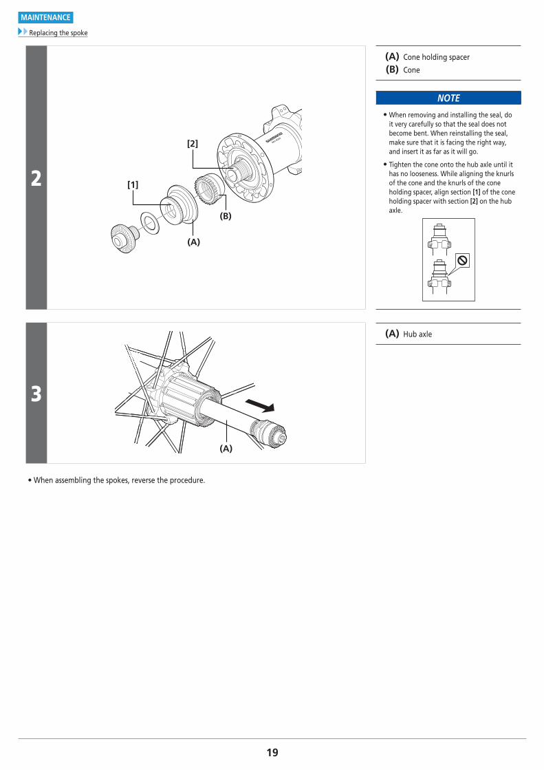
2
WH-900
0
(B)
(A)
[2]
[1]
(A) Cone holding spacer
(B) Cone
NOTE
• When removing and installing the seal, do it very carefully so that the seal does not become bent. When reinstalling the seal, make sure that it is facing the right way, and insert it as far as it will go.
• Tighten the cone onto the hub axle until it has no looseness. While aligning the knurls of the cone and the knurls of the cone holding spacer, align section [1] of the cone holding spacer with section [2] on the hub axle.
3
(A)
(A) Hub axle
• When assembling the spokes, reverse the procedure.
20To be continued on next page
MAINTENANCE
Replacing the spoke
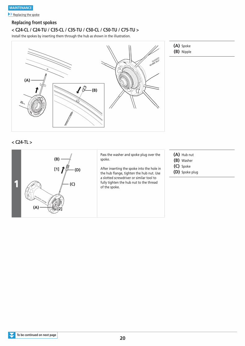
Replacing front spokes< C24-CL / C24-TU / C35-CL / C35-TU / C50-CL / C50-TU / C75-TU >Install the spokes by inserting them through the hub as shown in the illustration.
(B)
(A)
(A) Spoke
(B) Nipple
< C24-TL >
1
2
(D)
(C)
(A)
(B)
[1]
[2][2]
Pass the washer and spoke plug over the spoke.
After inserting the spoke into the hole in the hub flange, tighten the hub nut. Use a slotted screwdriver or similar tool to fully tighten the hub nut to the thread of the spoke.
(A) Hub nut
(B) Washer
(C) Spoke
(D) Spoke plug
21
MAINTENANCE
Replacing the spoke
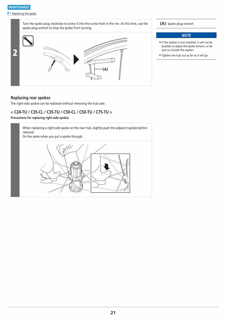
2
Turn the spoke plug clockwise to screw it into the screw hole in the rim. At this time, use the spoke plug wrench to stop the spoke from turning.
(A) Spoke plug wrench
NOTE
• If the washer is not installed, it will not be possible to adjust the spoke tension, so be sure to include the washer.
• Tighten the hub nut as far as it will go.
(A)
Replacing rear spokesThe right-side spokes can be replaced without removing the hub axle.
< C24-TU / C35-CL / C35-TU / C50-CL / C50-TU / C75-TU >Precautions for replacing right-side spokes
When replacing a right-side spoke on the rear hub, slightly push the adjacent spokes before removal. Do the same when you put a spoke through.
22
MAINTENANCE
Replacing the spoke
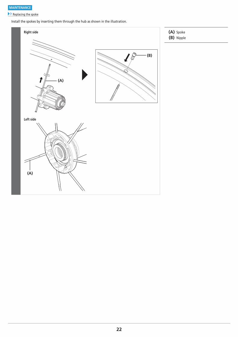
Install the spokes by inserting them through the hub as shown in the illustration.
Right side
(B)
(A)
Left side
(A)
(A) Spoke
(B) Nipple
23
MAINTENANCE
Replacing the spoke
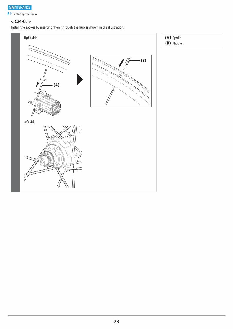
< C24-CL >Install the spokes by inserting them through the hub as shown in the illustration.
Right side
(B)
(A)
Left side
(A) Spoke
(B) Nipple
24
MAINTENANCE
Replacing the spoke
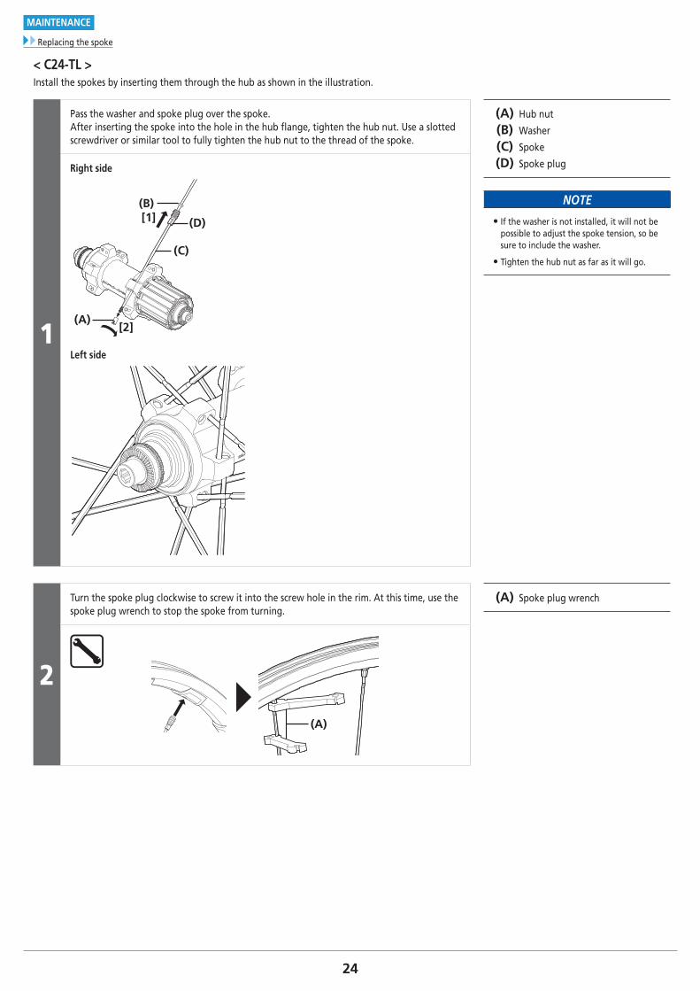
< C24-TL >Install the spokes by inserting them through the hub as shown in the illustration.
1
Pass the washer and spoke plug over the spoke.After inserting the spoke into the hole in the hub flange, tighten the hub nut. Use a slotted screwdriver or similar tool to fully tighten the hub nut to the thread of the spoke.
(A) Hub nut
(B) Washer
(C) Spoke
(D) Spoke plug
NOTE
• If the washer is not installed, it will not be possible to adjust the spoke tension, so be sure to include the washer.
• Tighten the hub nut as far as it will go.
Right side
(B)
(D)
(C)
(A)
[1]
[2]
Left side
2
Turn the spoke plug clockwise to screw it into the screw hole in the rim. At this time, use the spoke plug wrench to stop the spoke from turning.
(A) Spoke plug wrench
(A)
25
MAINTENANCE
Replacing the spoke
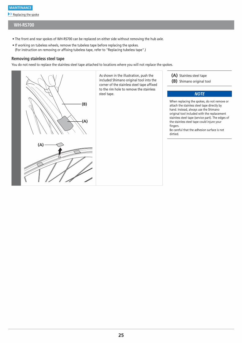
WH-RS700
• The front and rear spokes of WH-RS700 can be replaced on either side without removing the hub axle.
• If working on tubeless wheels, remove the tubeless tape before replacing the spokes. (For instruction on removing or affixing tubeless tape, refer to "Replacing tubeless tape".)
Removing stainless steel tapeYou do not need to replace the stainless steel tape attached to locations where you will not replace the spokes.
(B)
(A)
(A)
As shown in the illustration, push the included Shimano original tool into the corner of the stainless steel tape affixed to the rim hole to remove the stainless steel tape.
(A) Stainless steel tape
(B) Shimano original tool
NOTE
When replacing the spokes, do not remove or attach the stainless steel tape directly by hand. Instead, always use the Shimano original tool included with the replacement stainless steel tape (service part). The edges of the stainless steel tape could injure your fingers. Be careful that the adhesion surface is not dirtied.
26
MAINTENANCE
Replacing the spoke
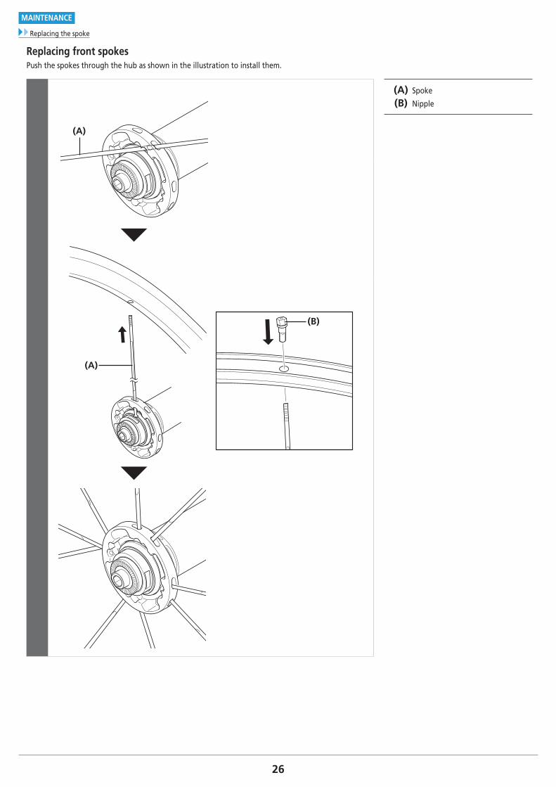
Replacing front spokesPush the spokes through the hub as shown in the illustration to install them.
(A)
(A)
(B)
(A) Spoke
(B) Nipple
27
MAINTENANCE
Replacing the spoke
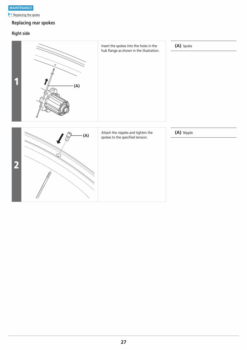
Replacing rear spokes
Right side
1 (A)
Insert the spokes into the holes in the hub flange as shown in the illustration.
(A) Spoke
2
(A)Attach the nipples and tighten the spokes to the specified tension.
(A) Nipple
28To be continued on next page
MAINTENANCE
Replacing the spoke
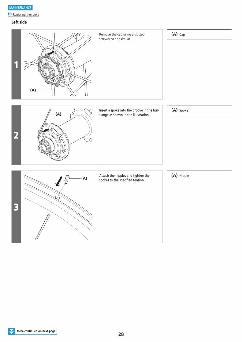
Left side
1
(A)
Remove the cap using a slotted screwdriver or similar.
(A) Cap
2
(A)Insert a spoke into the groove in the hub flange as shown in the illustration.
(A) Spoke
3
(A)Attach the nipples and tighten the spokes to the specified tension.
(A) Nipple
29To be continued on next page
MAINTENANCE
Replacing the spoke
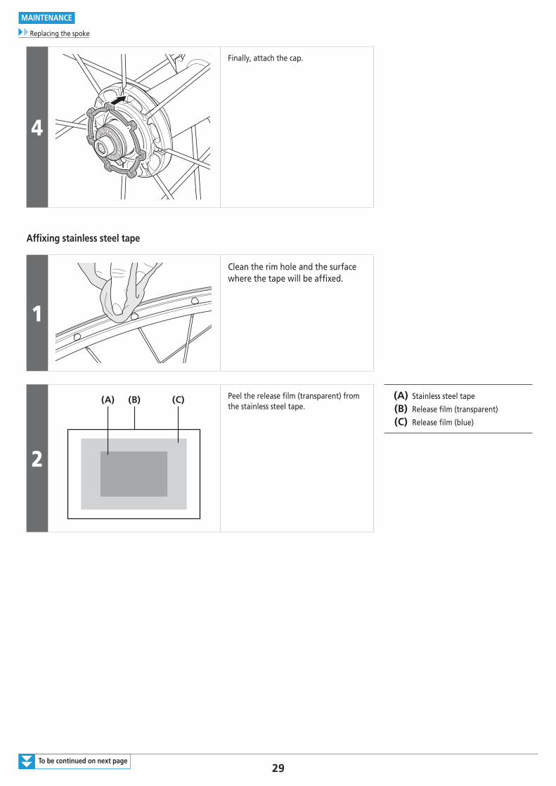
4
Finally, attach the cap.
Affixing stainless steel tape
1
Clean the rim hole and the surface where the tape will be affixed.
2
(A) (B) (C) Peel the release film (transparent) from the stainless steel tape.
(A) Stainless steel tape
(B) Release film (transparent)
(C) Release film (blue)
30
MAINTENANCE
Replacing the spoke
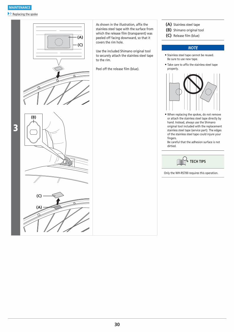
3
(A)
(C)
(B)
(C)
(A)
As shown in the illustration, affi x the stainless steel tape with the surface from which the release fi lm (transparent) was peeled off facing downward, so that it covers the rim hole.
Use the included Shimano original tool to securely attach the stainless steel tape to the rim.
Peel off the release fi lm (blue).
(A) Stainless steel tape
(B) Shimano original tool
(C) Release fi lm (blue)
NOTE
• Stainless steel tape cannot be reused.Be sure to use new tape.
• Take care to affi x the stainless steel tape properly.
• When replacing the spokes, do not remove or attach the stainless steel tape directly by hand. Instead, always use the Shimano original tool included with the replacement stainless steel tape (service part). The edges of the stainless steel tape could injure your fi ngers. Be careful that the adhesion surface is not dirtied.
TECH TIPS
Only the WH-RS700 requires this operation.
31
MAINTENANCE
Replacing the spoke
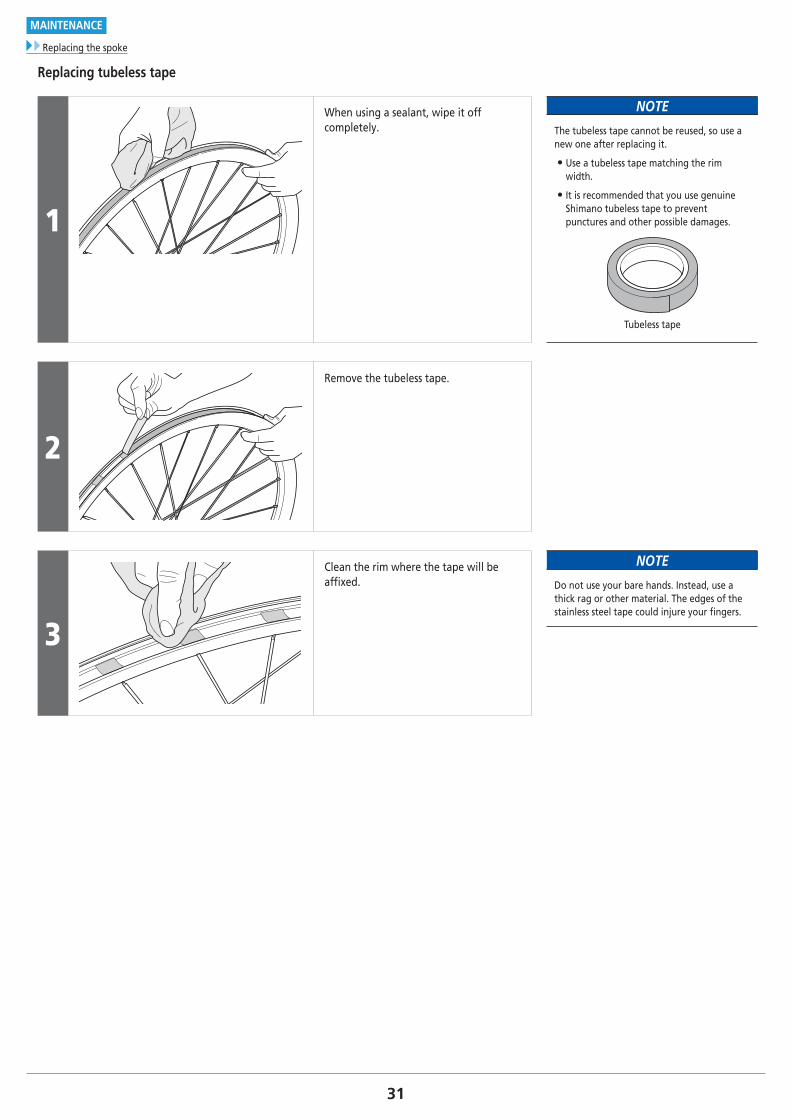
Replacing tubeless tape
1
When using a sealant, wipe it off completely.
NOTE
The tubeless tape cannot be reused, so use a new one after replacing it.
• Use a tubeless tape matching the rim width.
• It is recommended that you use genuine Shimano tubeless tape to prevent punctures and other possible damages.
Tubeless tape
2
Remove the tubeless tape.
3
Clean the rim where the tape will be affixed.
NOTE
Do not use your bare hands. Instead, use a thick rag or other material. The edges of the stainless steel tape could injure your fingers.
32To be continued on next page
MAINTENANCE
Replacing the spoke
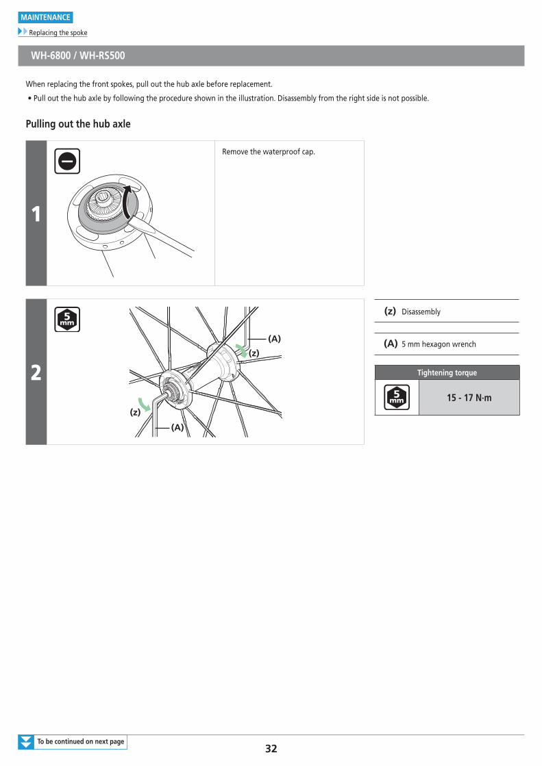
WH-6800 / WH-RS500
When replacing the front spokes, pull out the hub axle before replacement.
• Pull out the hub axle by following the procedure shown in the illustration. Disassembly from the right side is not possible.
Pulling out the hub axle
1
Remove the waterproof cap.
2
(A)
(A)
(z)
(z)
(z) Disassembly
(A) 5 mm hexagon wrench
Tightening torque
15 - 17 N·m
33
MAINTENANCE
Replacing the spoke
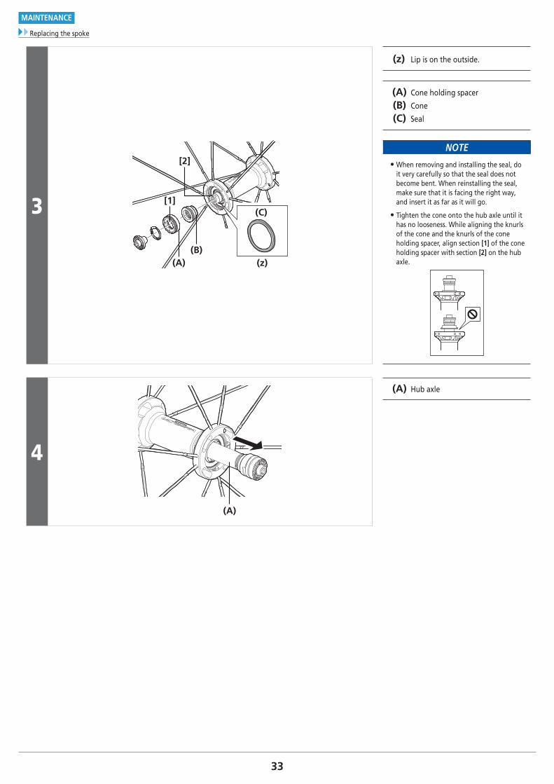
3
(A)(B)
(C)
(z)
[1]
[2]
(z) Lip is on the outside.
(A) Cone holding spacer
(B) Cone
(C) Seal
NOTE
• When removing and installing the seal, do it very carefully so that the seal does not become bent. When reinstalling the seal, make sure that it is facing the right way, and insert it as far as it will go.
• Tighten the cone onto the hub axle until it has no looseness. While aligning the knurls of the cone and the knurls of the cone holding spacer, align section [1] of the cone holding spacer with section [2] on the hub axle.
4
(A)
(A) Hub axle
34
MAINTENANCE
Replacing the spoke
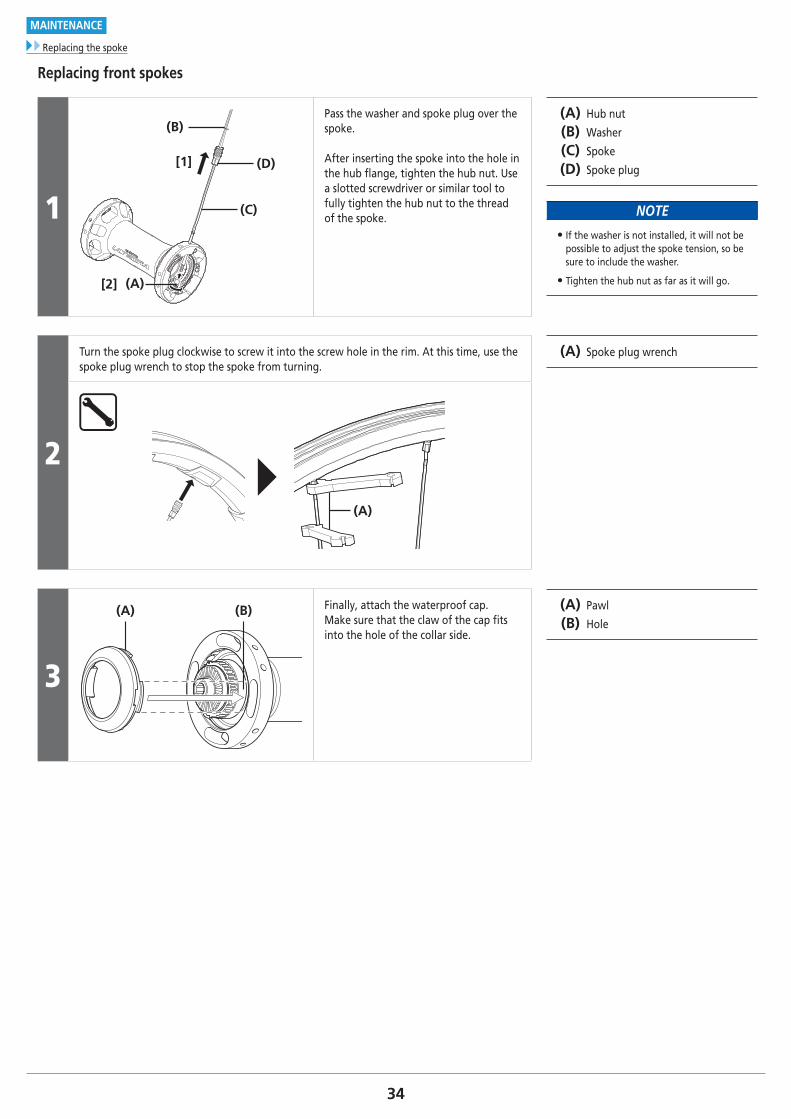
Replacing front spokes
1
33
(B)
(A)
(D)
(C)
[1]
[2]
Pass the washer and spoke plug over the spoke.
After inserting the spoke into the hole in the hub flange, tighten the hub nut. Use a slotted screwdriver or similar tool to fully tighten the hub nut to the thread of the spoke.
(A) Hub nut
(B) Washer
(C) Spoke
(D) Spoke plug
NOTE
• If the washer is not installed, it will not be possible to adjust the spoke tension, so be sure to include the washer.
• Tighten the hub nut as far as it will go.
2
Turn the spoke plug clockwise to screw it into the screw hole in the rim. At this time, use the spoke plug wrench to stop the spoke from turning.
(A) Spoke plug wrench
(A)
3
(A) (B) Finally, attach the waterproof cap.Make sure that the claw of the cap fits into the hole of the collar side.
(A) Pawl
(B) Hole

35
MAINTENANCE
Replacing the spoke
Replacing rear spokesThe rear spokes can be replaced without removing the hub axle.Install the spokes by inserting them through the hub as shown in the illustration.
1
Pass the washer and spoke plug over the spoke.After inserting the spoke into the hole in the hub flange, tighten the hub nut. Use a slotted screwdriver or similar tool to fully tighten the hub nut to the thread of the spoke.
(A) Hub nut
(B) Washer
(C) Spoke
(D) Spoke plug
NOTE
• If the washer is not installed, it will not be possible to adjust the spoke tension, so be sure to include the washer.
• Tighten the hub nut as far as it will go.
Right side
(B)
(D)
(C)
(A)
[1]
[2]
Left side
2
Turn the spoke plug clockwise to screw it into the screw hole in the rim. At this time, use the spoke plug wrench to stop the spoke from turning.
(A) Spoke plug wrench
(A)
36
MAINTENANCE
Replacing the spoke
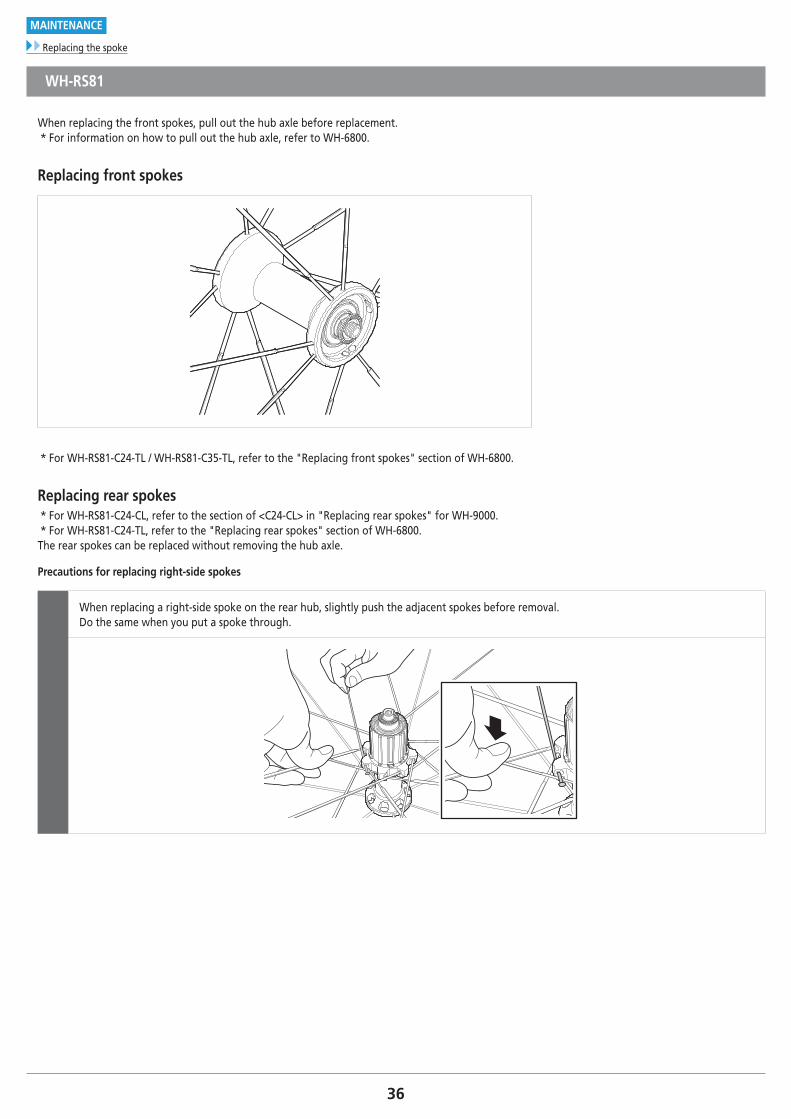
WH-RS81
When replacing the front spokes, pull out the hub axle before replacement.* For information on how to pull out the hub axle, refer to WH-6800.
Replacing front spokes
* For WH-RS81-C24-TL / WH-RS81-C35-TL, refer to the "Replacing front spokes" section of WH-6800.
Replacing rear spokes* For WH-RS81-C24-CL, refer to the section of <C24-CL> in "Replacing rear spokes" for WH-9000.* For WH-RS81-C24-TL, refer to the "Replacing rear spokes" section of WH-6800.The rear spokes can be replaced without removing the hub axle.
Precautions for replacing right-side spokes
When replacing a right-side spoke on the rear hub, slightly push the adjacent spokes before removal. Do the same when you put a spoke through.
37
MAINTENANCE
Replacing the spoke
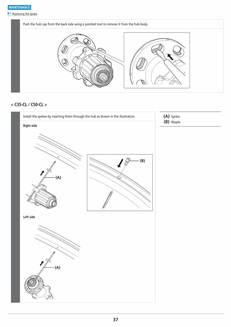
Push the hub cap from the back side using a pointed tool to remove it from the hub body.
< C35-CL / C50-CL >
Install the spokes by inserting them through the hub as shown in the illustration. (A) Spoke
(B) NippleRight side
(B)
(A)
Left side
(A)
38
MAINTENANCE
Replacing the spoke
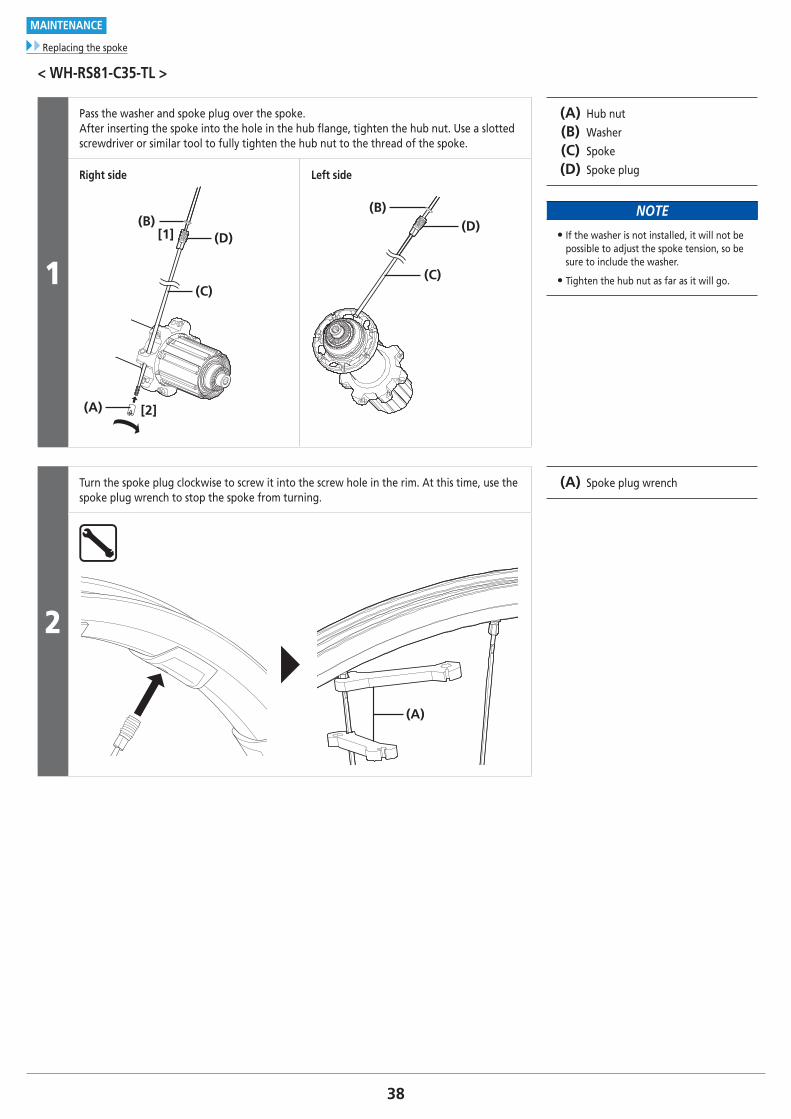
< WH-RS81-C35-TL >
1
Pass the washer and spoke plug over the spoke.After inserting the spoke into the hole in the hub flange, tighten the hub nut. Use a slotted screwdriver or similar tool to fully tighten the hub nut to the thread of the spoke.
(A) Hub nut
(B) Washer
(C) Spoke
(D) Spoke plug
NOTE
• If the washer is not installed, it will not be possible to adjust the spoke tension, so be sure to include the washer.
• Tighten the hub nut as far as it will go.
Right side
(A)
(C)
(B)(D)[1]
[2]
Left side
(C)
(D)(B)
2
Turn the spoke plug clockwise to screw it into the screw hole in the rim. At this time, use the spoke plug wrench to stop the spoke from turning.
(A) Spoke plug wrench
(A)
39To be continued on next page
MAINTENANCE
Replacing the spoke
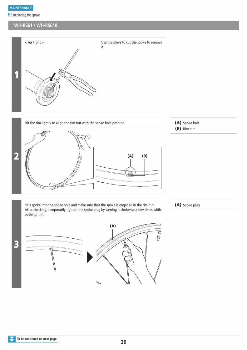
WH-RS61 / WH-RS610
1
< For front > Use the pliers to cut the spoke to remove it.
2
Hit the rim lightly to align the rim nut with the spoke hole position. (A) Spoke hole
(B) Rim nut
(A) (B)
3
Fit a spoke into the spoke hole and make sure that the spoke is engaged in the rim nut. After checking, temporarily tighten the spoke plug by turning it clockwise a few times while pushing it in.
(A) Spoke plug
(A)
40
MAINTENANCE
Replacing the spoke
4
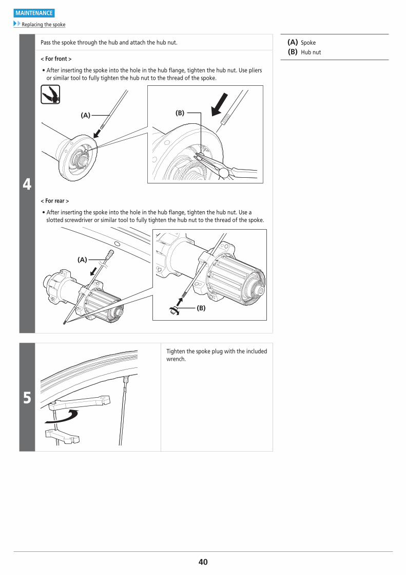
Pass the spoke through the hub and attach the hub nut. (A) Spoke
(B) Hub nut< For front >
• After inserting the spoke into the hole in the hub flange, tighten the hub nut. Use pliers or similar tool to fully tighten the hub nut to the thread of the spoke.
(A) (B)
< For rear >
• After inserting the spoke into the hole in the hub flange, tighten the hub nut. Use a slotted screwdriver or similar tool to fully tighten the hub nut to the thread of the spoke.
(B)
(A)
5
Tighten the spoke plug with the included wrench.
41
MAINTENANCE
Replacing the spoke
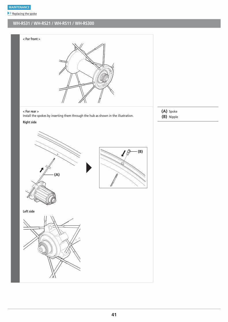
WH-RS31 / WH-RS21 / WH-RS11 / WH-RS300
< For front >
< For rear >Install the spokes by inserting them through the hub as shown in the illustration.
Right side
(B)
(A)
Left side
(A) Spoke
(B) Nipple
42
MAINTENANCE
Replacing the spoke
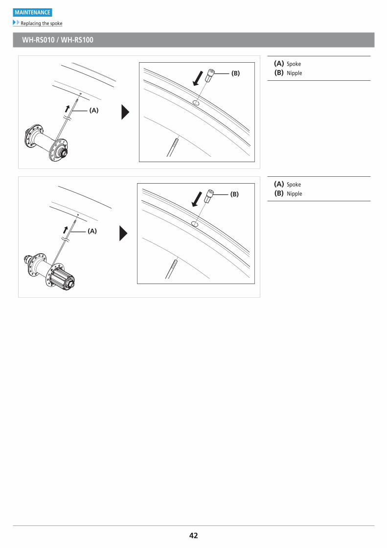
WH-RS010 / WH-RS100
(B)
(A)
(A) Spoke
(B) Nipple
(B)
(A)
(A) Spoke
(B) Nipple
43
MAINTENANCE
Replacing the spoke
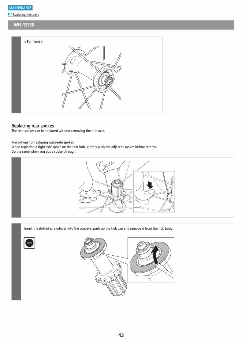
WH-RS330
< For front >
Replacing rear spokesThe rear spokes can be replaced without removing the hub axle.
Precautions for replacing right-side spokesWhen replacing a right-side spoke on the rear hub, slightly push the adjacent spokes before removal. Do the same when you put a spoke through.
Insert the slotted screwdriver into the concave, push up the hub cap and remove it from the hub body.
44
MAINTENANCE
Replacing the spoke
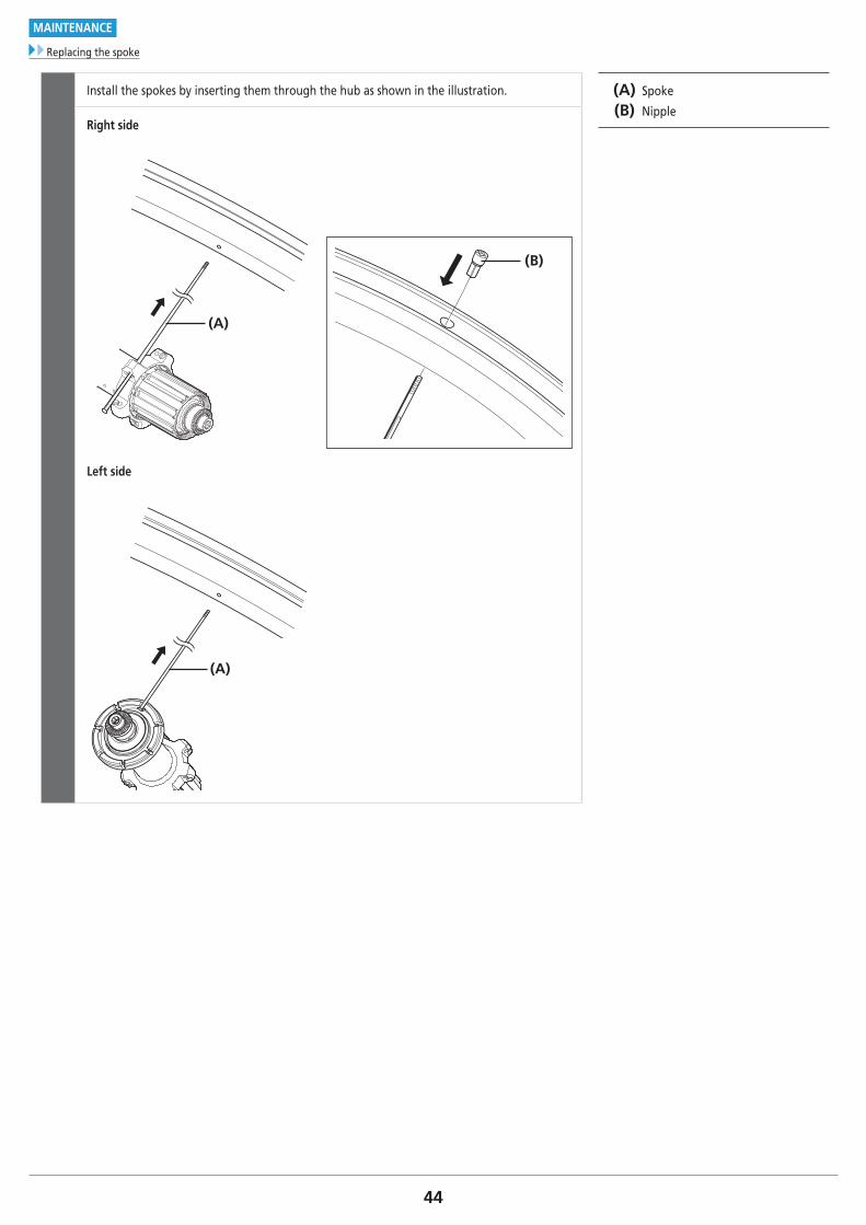
Install the spokes by inserting them through the hub as shown in the illustration. (A) Spoke
(B) NippleRight side
(B)
(A)
Left side
(A)
45
MAINTENANCE
Replacement of the freewheel body
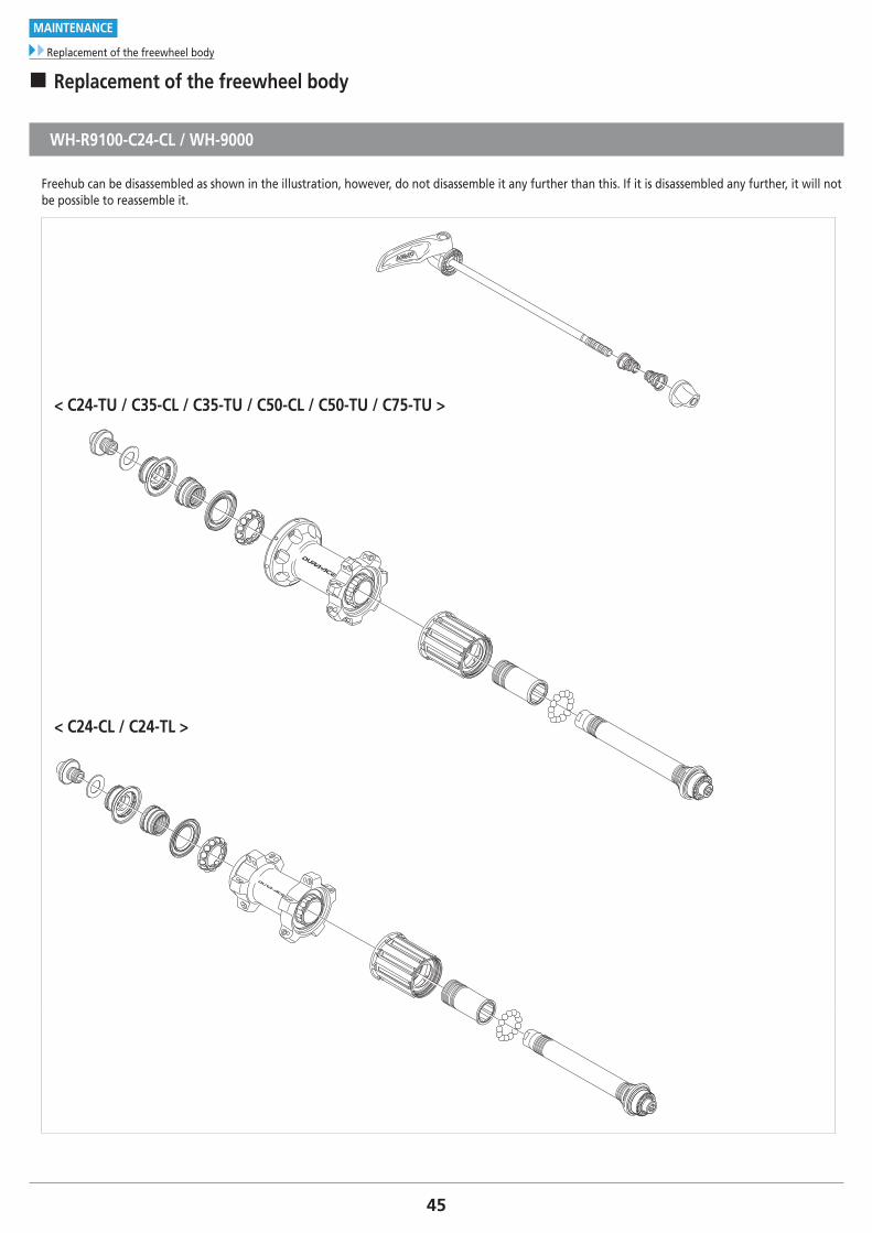
� Replacement of the freewheel body
WH-R9100-C24-CL / WH-9000
Freehub can be disassembled as shown in the illustration, however, do not disassemble it any further than this. If it is disassembled any further, it will not be possible to reassemble it.
< C24-TU / C35-CL / C35-TU / C50-CL / C50-TU / C75-TU >
< C24-CL / C24-TL >
46
MAINTENANCE
Replacement of the freewheel body
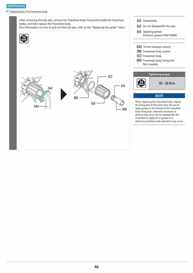
After removing the hub axle, remove the freewheel body fixing bolt (inside the freewheel body), and then replace the freewheel body.(For information on how to pull out the hub axle, refer to the "Replacing the spoke" item.)
(x) Disassembly
(y) Do not disassemble the seal.
(z) Applying grease Premium grease (Y04110000)
(A) 14 mm hexagon wrench
(B) Freewheel body washer
(C) Freewheel body
(D) Freewheel body fixing bolt Not reusable
Tightening torque
45 - 50 N·m
NOTE
When replacing the freewheel body, replace the fixing bolt at the same time. Be sure to apply grease to the thread of the freewheel body fixing bolt, otherwise looseness or sticking may occur. Do not disassemble the freewheel or apply oil or grease to it, otherwise problems with operation may occur.
(x)
(A)
(B)
(C)
(y)
(D)
(z)
47
MAINTENANCE
Replacement of the freewheel body
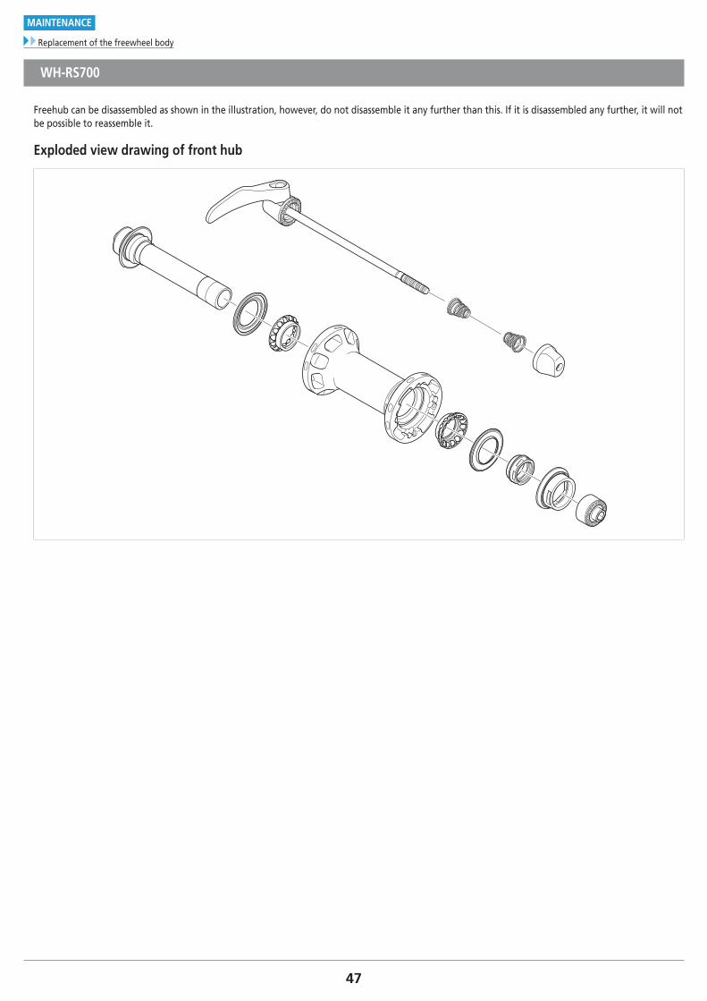
WH-RS700
Freehub can be disassembled as shown in the illustration, however, do not disassemble it any further than this. If it is disassembled any further, it will not be possible to reassemble it.
Exploded view drawing of front hub
48
MAINTENANCE
Replacement of the freewheel body
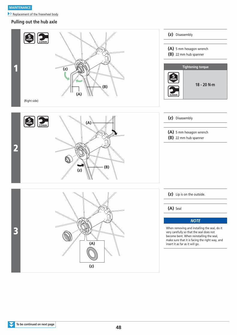
Pulling out the hub axle
1
(A)
(B)
(z)
(Right side)
(z) Disassembly
(A) 5 mm hexagon wrench
(B) 22 mm hub spanner
Tightening torque
18 - 20 N·m
2
(z)(B)
(A)(z) Disassembly
(A) 5 mm hexagon wrench
(B) 22 mm hub spanner
3(A)
(z)
(z) Lip is on the outside.
(A) Seal
NOTE
When removing and installing the seal, do it very carefully so that the seal does not become bent. When reinstalling the seal, make sure that it is facing the right way, and insert it as far as it will go.
To be continued on next page
49
MAINTENANCE
Replacement of the freewheel body
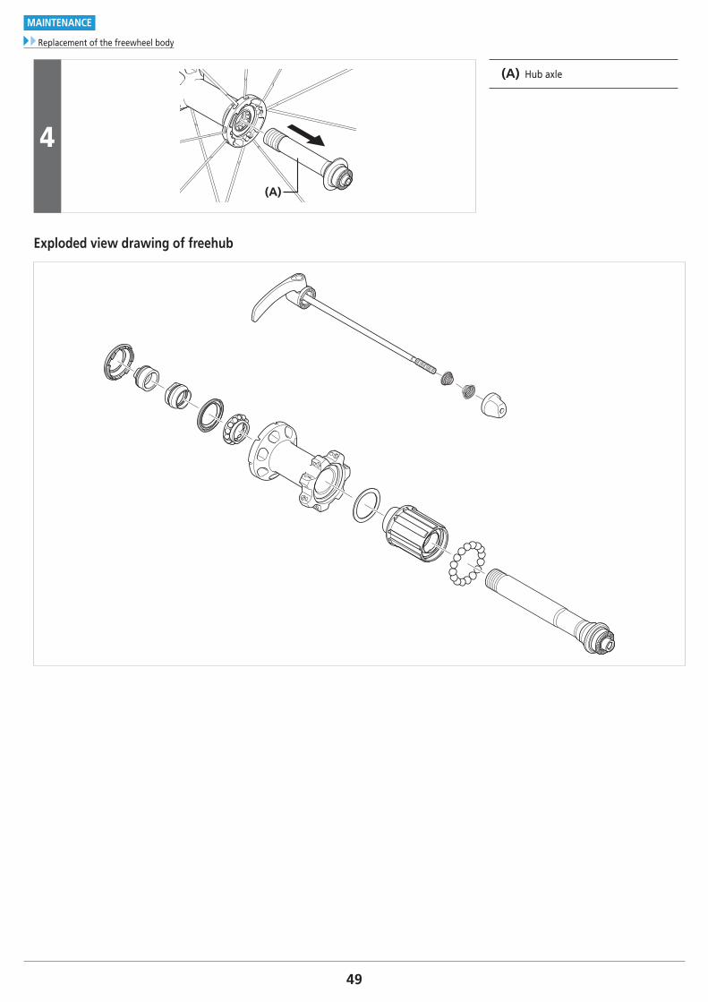
4
(A)
(A) Hub axle
Exploded view drawing of freehub
50
MAINTENANCE
Replacement of the freewheel body
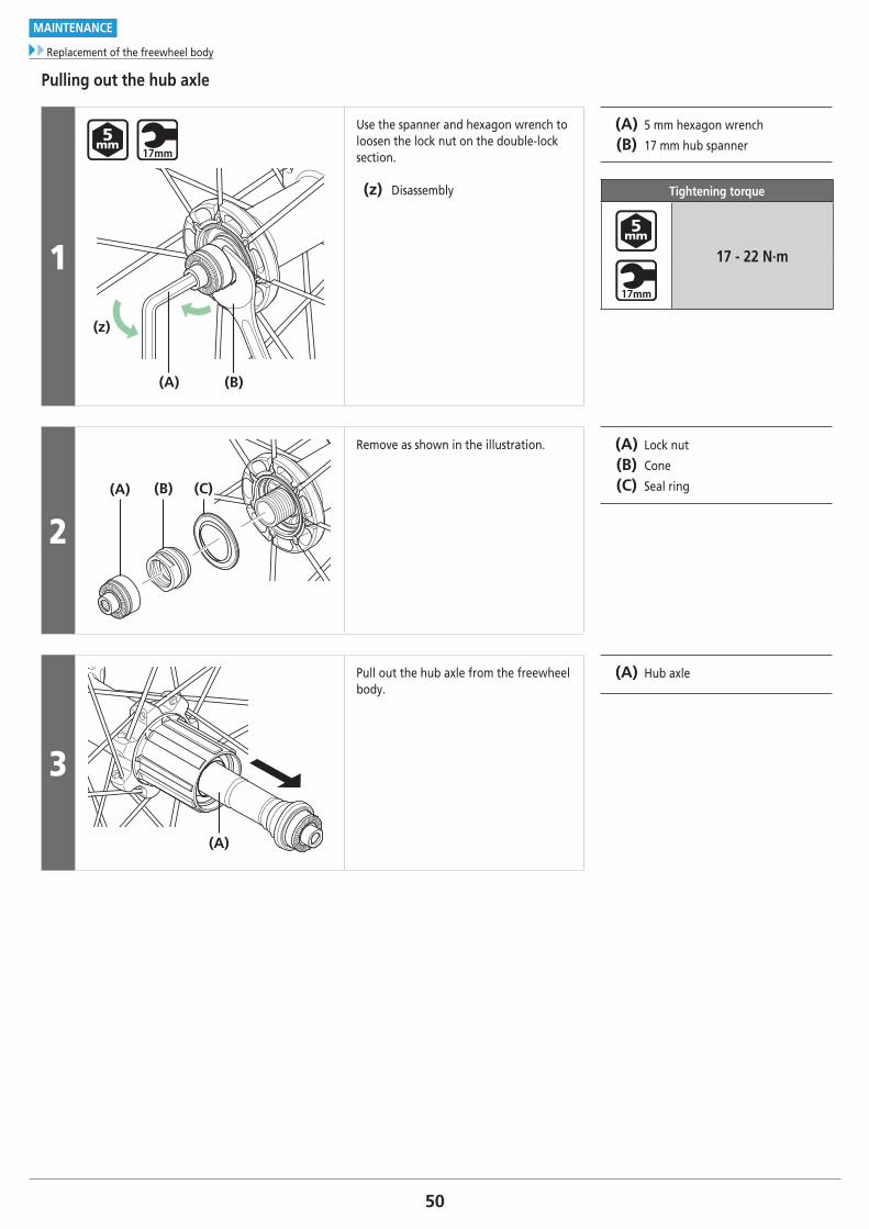
Pulling out the hub axle
1
(z)
(B)(A)
Use the spanner and hexagon wrench to loosen the lock nut on the double-lock section.
(z) Disassembly
(A) 5 mm hexagon wrench
(B) 17 mm hub spanner
Tightening torque
17 - 22 N·m
2(A) (B) (C)
Remove as shown in the illustration. (A) Lock nut
(B) Cone
(C) Seal ring
3
(A)
Pull out the hub axle from the freewheel body.
(A) Hub axle
51
MAINTENANCE
Replacement of the freewheel body
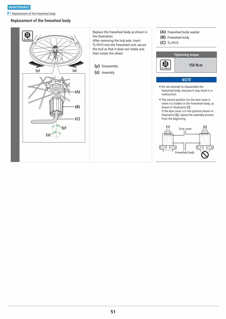
Replacement of the freewheel body
(y) (z)
(y)
(z)
(B)
(A)
(C)
Replace the freewheel body as shown in the illustration. After removing the hub axle, insert TL-FH15 into the freewheel unit, secure the tool so that it does not rotate and then rotate the wheel.
(y) Disassembly
(z) Assembly
(A) Freewheel body washer
(B) Freewheel body
(C) TL-FH15
Tightening torque
150 N·m
NOTE
• Do not attempt to disassemble the freewheel body, because it may result in a malfunction.
• The correct position for the dust cover is when it is hidden in the freewheel body, as shown in illustration [1]. If the dust cover is in the position shown in illustration [2], repeat the assembly process from the beginning.
[1] [2]
Freewheel body
Dust cover
52
MAINTENANCE
Replacement of the freewheel body
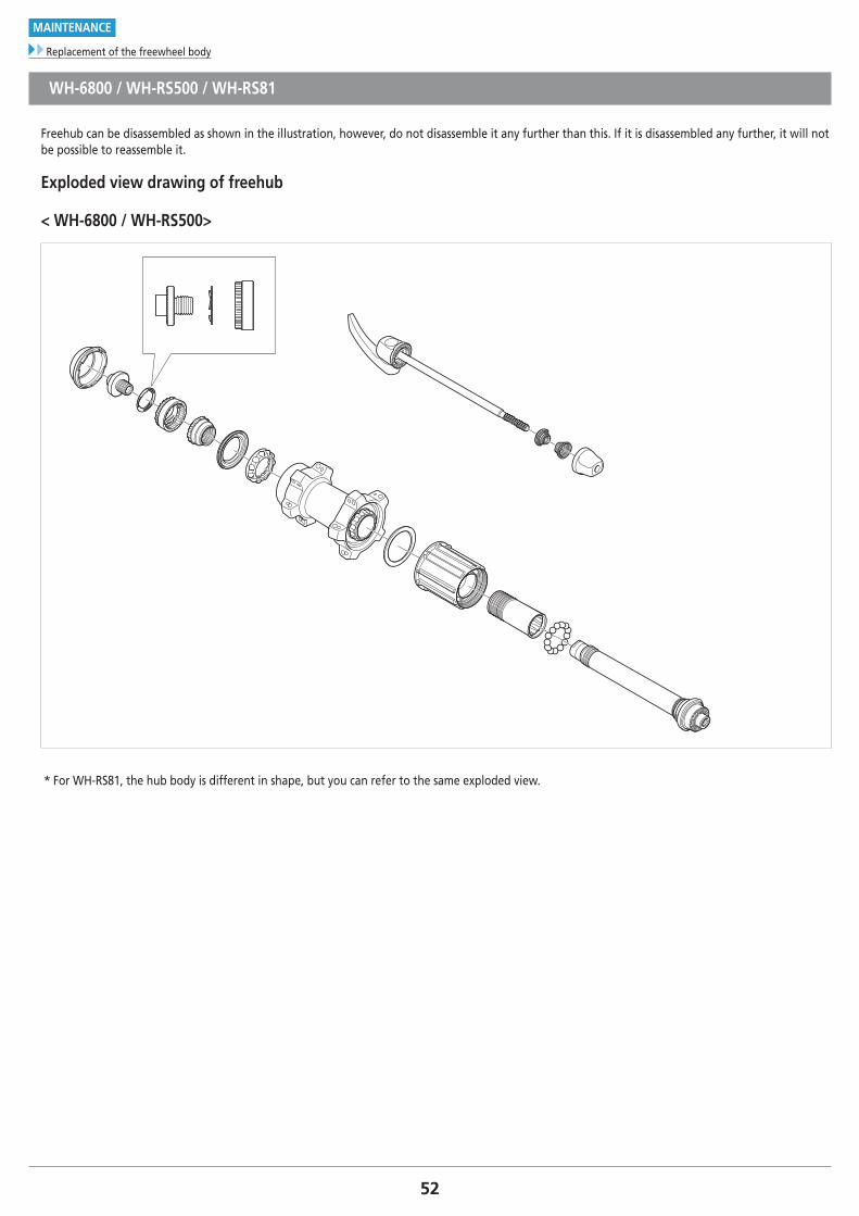
WH-6800 / WH-RS500 / WH-RS81
Freehub can be disassembled as shown in the illustration, however, do not disassemble it any further than this. If it is disassembled any further, it will not be possible to reassemble it.
Exploded view drawing of freehub
< WH-6800 / WH-RS500>
* For WH-RS81, the hub body is different in shape, but you can refer to the same exploded view.
53
MAINTENANCE
Replacement of the freewheel body
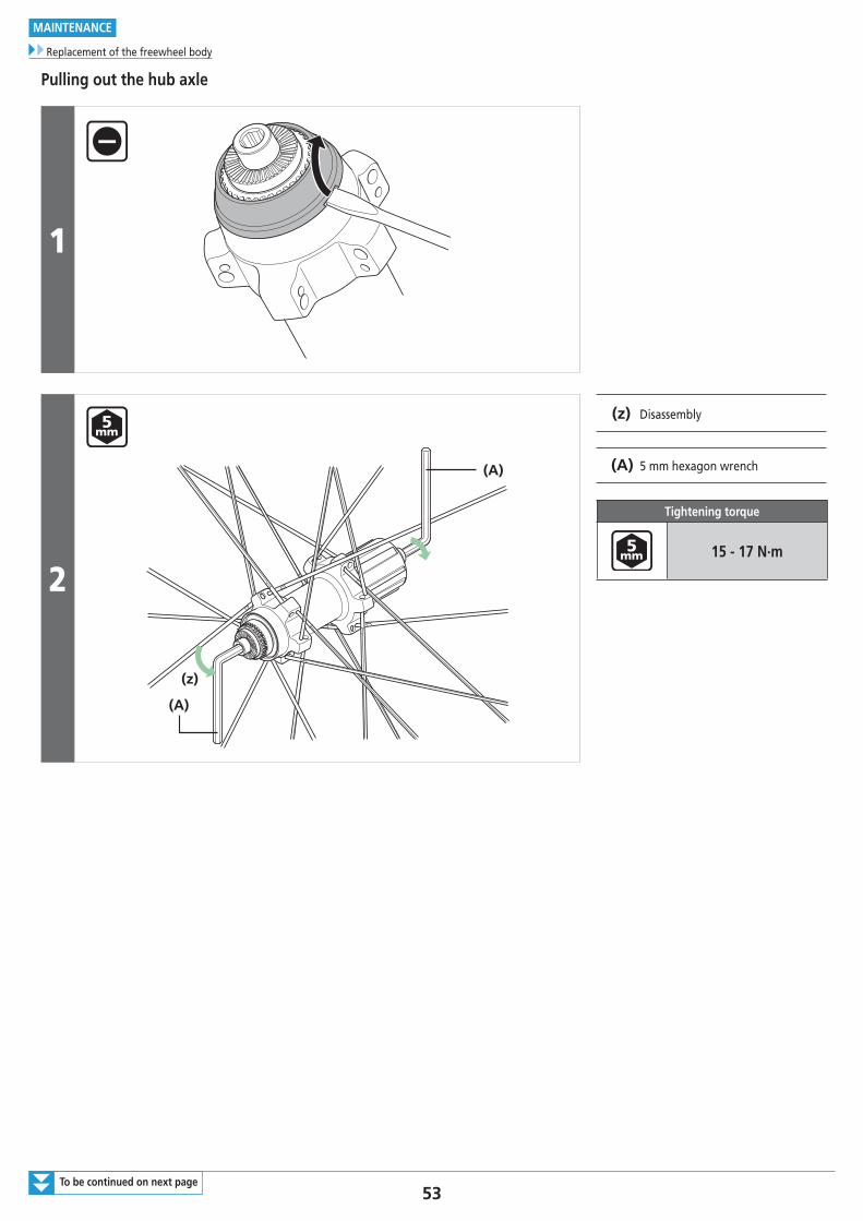
Pulling out the hub axle
1
2
(A)
(z)
(A)
(z) Disassembly
(A) 5 mm hexagon wrench
Tightening torque
15 - 17 N·m
To be continued on next page
54
MAINTENANCE
Replacement of the freewheel body
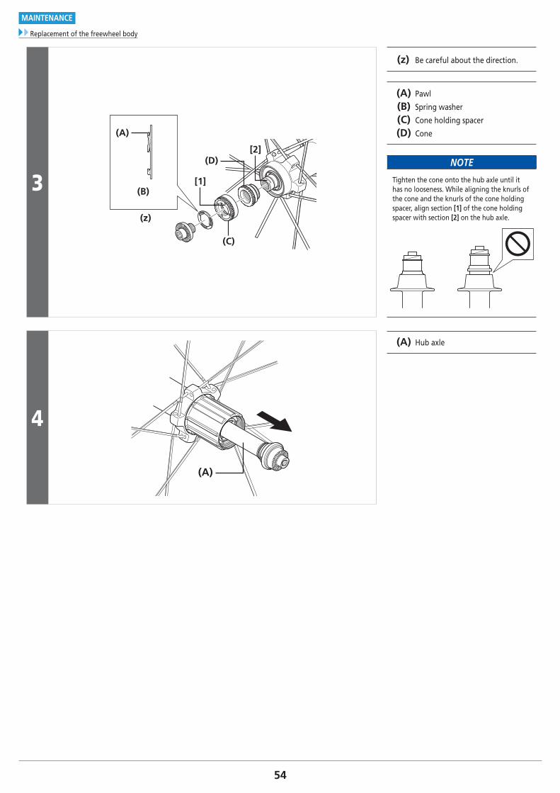
3
(A)
(B)
(z)
(C)
(D)[2]
[1]
(z) Be careful about the direction.
(A) Pawl
(B) Spring washer
(C) Cone holding spacer
(D) Cone
NOTE
Tighten the cone onto the hub axle until it has no looseness. While aligning the knurls of the cone and the knurls of the cone holding spacer, align section [1] of the cone holding spacer with section [2] on the hub axle.
4
(A)
(A) Hub axle
55
MAINTENANCE
Replacement of the freewheel body
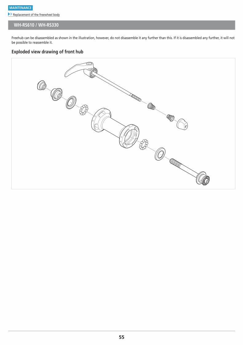
WH-RS610 / WH-RS330
Freehub can be disassembled as shown in the illustration, however, do not disassemble it any further than this. If it is disassembled any further, it will not be possible to reassemble it.
Exploded view drawing of front hub
56To be continued on next page
MAINTENANCE
Replacement of the freewheel body
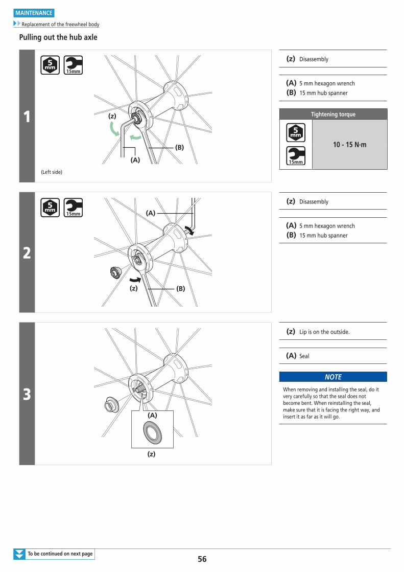
Pulling out the hub axle
1
(A)
(B)
(z)
(Left side)
(z) Disassembly
(A) 5 mm hexagon wrench
(B) 15 mm hub spanner
Tightening torque
10 - 15 N·m
2
(z) (B)
(A)
(z) Disassembly
(A) 5 mm hexagon wrench
(B) 15 mm hub spanner
3(A)
(z)
(z) Lip is on the outside.
(A) Seal
NOTE
When removing and installing the seal, do it very carefully so that the seal does not become bent. When reinstalling the seal, make sure that it is facing the right way, and insert it as far as it will go.
57
MAINTENANCE
Replacement of the freewheel body
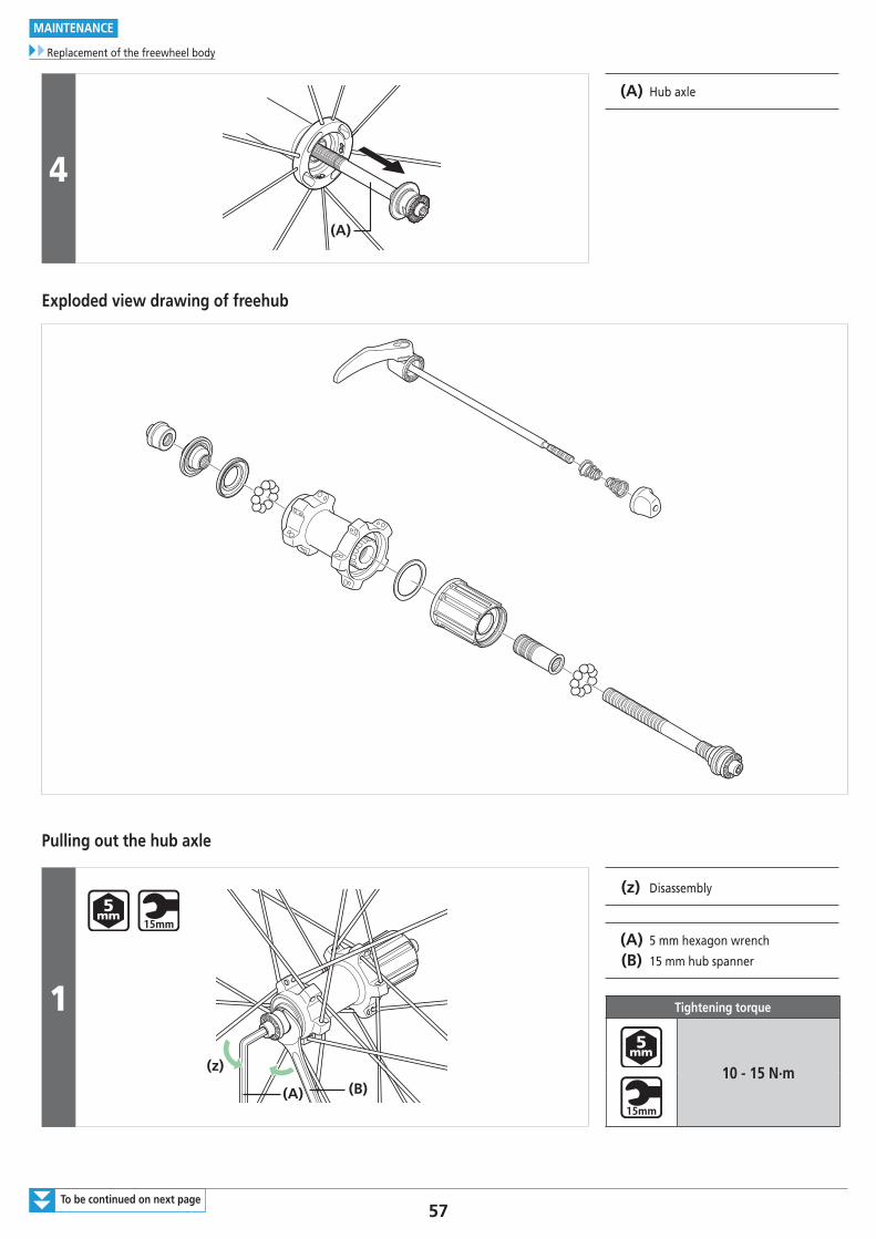
4
(A)
(A) Hub axle
Exploded view drawing of freehub
Pulling out the hub axle
1
(A) (B)
(z)
(z) Disassembly
(A) 5 mm hexagon wrench
(B) 15 mm hub spanner
Tightening torque
10 - 15 N·m
To be continued on next page
58
MAINTENANCE
Replacement of the freewheel body
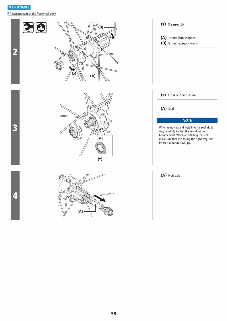
2
(A)
(B)
(z)
(z) Disassembly
(A) 15 mm hub spanner
(B) 5 mm hexagon wrench
3(A)
(z)
(z) Lip is on the outside.
(A) Seal
NOTE
When removing and installing the seal, do it very carefully so that the seal does not become bent. When reinstalling the seal, make sure that it is facing the right way, and insert it as far as it will go.
4
(A)
(A) Hub axle

59
MAINTENANCE
Replacement of the freewheel body
WH-RS010 / WH-RS61 / WH-RS31 / WH-RS21 / WH-RS11 / WH-RS300 / WH-RS100
Pulling out the hub axle
1(z)
(A)
(B)
(z) Disassembly
(A) 15 mm hub spanner
(B) 17 mm hub spanner
Tightening torque
10 - 15 N·m
WH-RS010/WH-RS61
Tightening torque
8 - 13 N·m
WH-RS31/WH-RS21/WH-RS11/WH-RS300/WH-RS100
2
(C)
(B)(A)
(A) Lock nut
(B) Axle spacer
(C) Cone
3
(A)
(A) Hub axle
60
MAINTENANCE
Replacement of the freewheel body
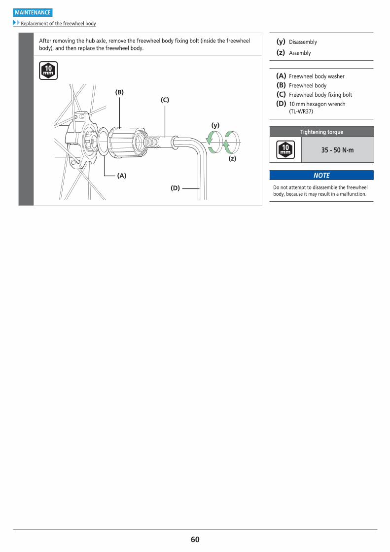
After removing the hub axle, remove the freewheel body fixing bolt (inside the freewheel body), and then replace the freewheel body.
(y) Disassembly
(z) Assembly
(A) Freewheel body washer
(B) Freewheel body
(C) Freewheel body fixing bolt
(D) 10 mm hexagon wrench (TL-WR37)
Tightening torque
35 - 50 N·m
NOTE
Do not attempt to disassemble the freewheel body, because it may result in a malfunction.
(D)
(B)
(A)
(C)
(y)
(z)
61To be continued on next page
MAINTENANCE
Installing and removing tubeless tires
� Installing and removing tubeless tires
TO ENSURE SAFETY
WARNING
• The tires should be installed and removed by hand. If this is difficult, a plastic tire lever for tubeless wheels may be used. In such cases, be sure to check that the rim surface has not been dented, scratched, or cracked as there is a risk of causing damage to the air seal between the tire and the rim, which would result in air leakage. For carbon rims, check that there is no carbon peeling or cracking etc. Finally, make sure there is no air leakage.
• Read these Technical Service Instructions carefully, and keep them in a safe place for later reference.
CAUTION
• Do not use rim tape if using an inner tube. Rim tape may make it difficult to remove and install the tire, and the tire or tube may become damaged or the tires may suddenly puncture and come off, and severe injury may result.
• Do not tighten the valve nut too much, otherwise the valve seal may become warped and air leaks may occur.
NOTE
• If the tires are difficult to fit, use tap water or soapy water to help them slide more easily.
• Products are not guaranteed against natural wear and deterioration from normal use and aging.
Technical Service Instructions
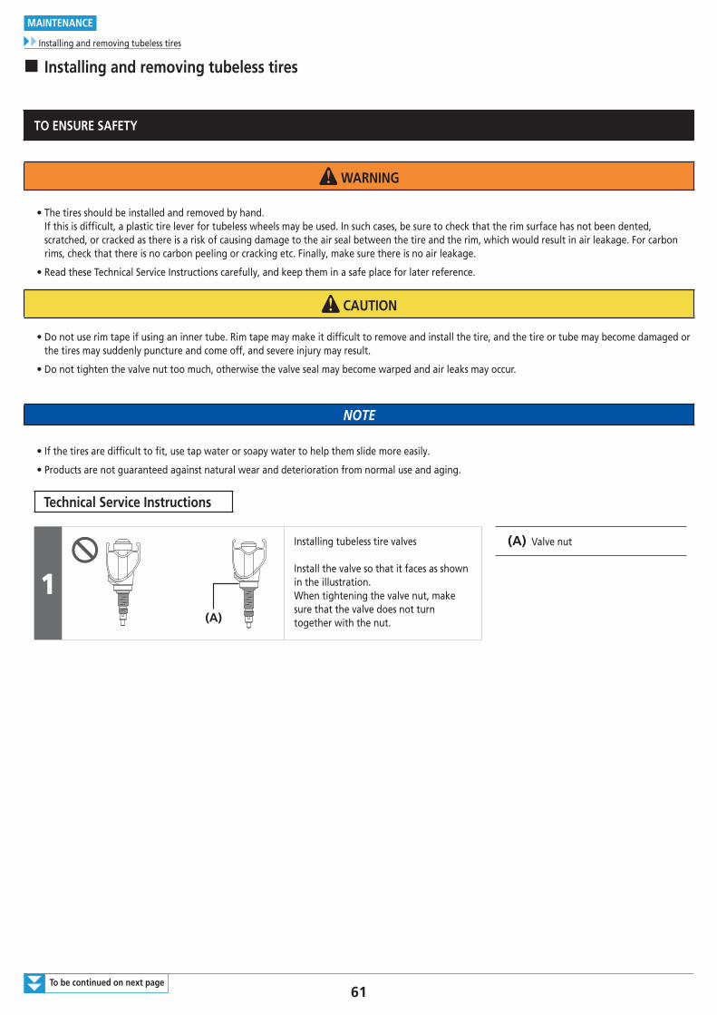
1(A)
Installing tubeless tire valves
Install the valve so that it faces as shown in the illustration. When tightening the valve nut, make sure that the valve does not turn together with the nut.
(A) Valve nut
62
MAINTENANCE
Installing and removing tubeless tires
2
(A)
(B)
(C)
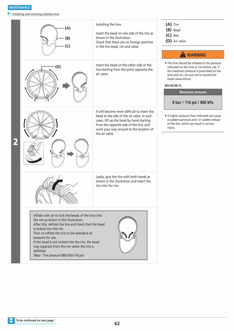
Installing the tires
Insert the bead on one side of the tire as shown in the illustration. Check that there are no foreign particles in the tire bead, rim and valve.
(A) Tire
(B) Bead
(C) Rim
(D) Air valve
WARNING
• The tires should be inflated to the pressure indicated on the tires or rim before use. If the maximum pressure is prescribed on the tires and rim, be sure not to exceed the lower value shown.
WH-RS700-TL
Maximum pressure
8 bar / 116 psi / 800 kPa
• A higher pressure than indicated can cause a sudden puncture and / or sudden release of the tire, which can result in serious injury.
(D) Insert the bead on the other side of the tire starting from the point opposite the air valve.
It will become more difficult to insert the bead at the side of the air valve. In such cases, lift up the bead by hand starting from the opposite side of the tire, and work your way around to the location of the air valve.
Lastly, grip the tire with both hands as shown in the illustration and insert the tire into the rim.
Inflate with air to lock the beads of the tires into the rim as shown in the illustration.After this, deflate the tire and check that the bead is locked into the rim. Then re-inflate the tire to the standard air pressure for use. If the bead is not locked into the rim, the bead may separate from the rim when the tire is deflated. (Max : Tire pressure 800 kPa/116 psi)
To be continued on next page
63
MAINTENANCE
Installing and removing tubeless tires
3
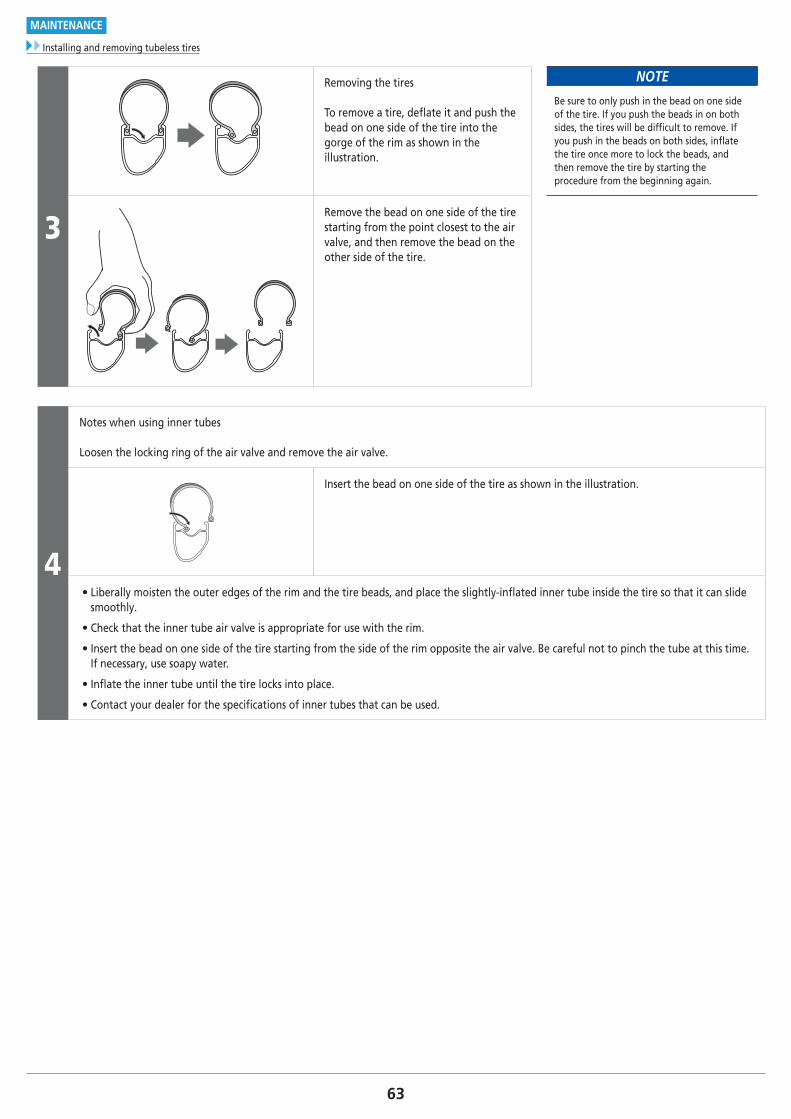
Removing the tires
To remove a tire, deflate it and push the bead on one side of the tire into the gorge of the rim as shown in the illustration.
NOTE
Be sure to only push in the bead on one side of the tire. If you push the beads in on both sides, the tires will be difficult to remove. If you push in the beads on both sides, inflate the tire once more to lock the beads, and then remove the tire by starting the procedure from the beginning again.
Remove the bead on one side of the tire starting from the point closest to the air valve, and then remove the bead on the other side of the tire.
4
Notes when using inner tubes
Loosen the locking ring of the air valve and remove the air valve.
Insert the bead on one side of the tire as shown in the illustration.
• Liberally moisten the outer edges of the rim and the tire beads, and place the slightly-inflated inner tube inside the tire so that it can slide smoothly.
• Check that the inner tube air valve is appropriate for use with the rim.
• Insert the bead on one side of the tire starting from the side of the rim opposite the air valve. Be careful not to pinch the tube at this time. If necessary, use soapy water.
• Inflate the inner tube until the tire locks into place.
• Contact your dealer for the specifications of inner tubes that can be used.
64
MAINTENANCE
Cautions on the use of tubular wheel rim
� Cautions on the use of tubular wheel rim
General Safety Information
WARNING
The Tubular Tire System is used widely in racing bicycles because of its lightweight design and smooth turning performance. However, a greater level of awareness in handling is required compared to clincher-type tires, and also a greater degree of care must be taken when carrying out maintenance work. In addition, always inspect the wheels prior to use.These precautions must be observed in order to maximize the performance of this product. If these precautions are not observed, the tires may come off the rims or damage to the tires may occur, and these could result in severe injury to the rider.Make sure that you read and fully understand the following points on using tubular tires. Furthermore, if you are not confident that you have enough knowledge and experience in installing and removing the tires or carrying out maintenance, ask an authorized bicycle dealer or a professional bicycle technician for assistance.Do not use these tubular tires if you are not confident that they have been installed by someone with an adequate level of knowledge and experience.
• A special adhesive designed exclusively for tubular tires is used to secure the tires to the wheel rims. If any other type of adhesive is used, it might not secure the tires in place with sufficient force, and it may also cause deterioration of the rim material.
• When cleaning the rim surfaces, use only a cleaning agent which is exclusively designed for tubular tires. If any other type of cleaning agent is used, it may cause deterioration of the rim material. If using carbon fiber rims, do not rub the surfaces of the rims vigorously with sandpaper or anything similar. Otherwise, the carbon fiber layer of the rims may peel off when replacing the tires.
• If the adhesive is not applied correctly to the rim surfaces, it may not hold the tires securely in place, and the tires may easily come off the rims. Particularly when using the rims for the first time, always be sure to clean the rim surfaces thoroughly with the correct cleaning agent to remove any traces of grease and other foreign materials. Then apply a thin layer of adhesive to the rim surface to create a secure bond between the rim and the wheel. When this has been done, apply more adhesive evenly to the rim at a thickness which is just sufficient to cover the roughness of the tire and no more, and then install the tire. When using rims which contain carbon fiber material, if the tires are not attached properly, or if the wrong type of adhesive or cleaning agent is used, it may not be possible to obtain the same degree of adhesion force between the rim and the tire as for aluminum rims, and it may also cause a reduction in the strength of the carbon fiber rims.
• Depending on the type of adhesive used, there may be large differences in factors such as adhesion force, the time it takes to dry, durability, and the sensitivity to conditions such as temperature and humidity. Therefore, you should pay particular attention to the adhesion force when using the wheels.
• Always check the tires before use by applying force to the tires to make sure they are properly attached to the rims.
• The adhesion force of the tires may deteriorate after long periods of use, therefore it is best to re-apply the adhesive periodically. If using carbon fiber rims, use a rim cement cleaner or similar when replacing the tires to assist in peeling the tires off gently in order to avoid pulling away the carbon fiber layer.
• If you do not apply any adhesive to the adhesion surface of the tire when installing the tire to the rim, the adhesion force between the tire and the rim will be weaker. If you want the tires to adhere to the rims with greater force (such as when riding in criterium competition races and track races where hard turning and acceleration are required) you can use adhesive to adhere them more firmly.
• If the rims become hot as a result of continuous use of the brakes when riding down long declines, sudden loss of tire adhesion force may occur. If you think that this might happen at some stage, pay particular attention to selecting and re-applying the adhesive at some point. Loss of adhesion force can still occur even if measures are taken to prevent it, so if it still occurs, replace the wheels and discontinue using the tubular type of tires.
• Also check the tires before use. If there are large cracks in the tires, they may burst during use, and so they should be replaced beforehand. In addition, the seam covers may come off the tires after long periods of use, and so check the tires before use.
• If you feel that there are any malfunctions or problems with the system, stop riding the bicycle and contact an authorized bicycle dealer or a professional bicycle technician for advice.
• For any questions regarding methods of installation, adjustment, maintenance or operation, please contact an authorized bicycle dealer.
NOTE
• If any glue gets on the painting surface of the rim, use a cloth to wipe it off before it dries. Do not use cleaning solvents or chemicals, such as rim cement removers, as they may remove the paint.

Please note: specifications are subject to change for improvement without notice. (English) © Mar. 2018 by Shimano Inc. ITP