Embed Size (px)
Citation preview

DMF-CI-8 DigitalMedia™ Chassis for
DM® NVX and DMCF Cards
Supplemental Guide Crestron Electronics, Inc.
The product warranty can be found at www.crestron.com/legal/sales-terms-conditions-warranties. The specific patents that cover Crestron products are listed at www.crestron.com/legal/patents. Certain Crestron products contain open source software. For specific information, visit www.crestron.com/legal/open-source-software. Crestron, the Crestron logo, Crestron Toolbox, DigitalMedia, and DM are either trademarks or registered trademarks of Crestron Electronics, Inc. in the United States and/or other countries. Other trademarks, registered trademarks, and trade names may be used in this document to refer to either the entities claiming the marks and names or their products. Crestron disclaims any proprietary interest in the marks and names of others. Crestron is not responsible for errors in typography or photography. This document was written by the Technical Publications department at Crestron. ©2018 Crestron Electronics, Inc.

Supplemental Guide – DOC. 7861C Contents • i
Contents Introduction ................................................................................................................................... 1
Physical Description .................................................................................................................... 2
Front Panel .......................................................................................................................................................................................................... 2 Rear Panel ............................................................................................................................................................................................................ 3
LCD Display Operation .............................................................................................................. 4
Card Status and Configuration ............................................................................................... 6
Configure the Device Mode ................................................................................................................................................................... 7 View and Configure Input Routing Settings .......................................................................................................................... 8
View Input Routing Settings ....................................................................................................................................................... 9 Configure Input Routing Settings ........................................................................................................................................ 10
View and Configure Network Settings ....................................................................................................................................... 11 View Network Settings .................................................................................................................................................................. 12 Configure IPv4 Settings ................................................................................................................................................................ 13
Perform Diagnostics.................................................................................................................................................................................. 16 View Card Details ............................................................................................................................................................................... 16 View Card Status ............................................................................................................................................................................... 17 Reset a Card ........................................................................................................................................................................................... 18 Restore a Card to the Factory Default Settings ..................................................................................................... 19
Chassis Status and Configuration......................................................................................... 20
View Chassis Details ........................................................................................................................................................................ 21 View Chassis Status ......................................................................................................................................................................... 21 Configure the Front Panel .......................................................................................................................................................... 22 Update Firmware ............................................................................................................................................................................... 23 Restore Factory Default Settings ........................................................................................................................................ 24


Supplemental Guide – DOC. 7861C DMF-CI-8: DM NVX and DMCF Card Chassis • 1
DMF-CI-8: DigitalMedia™ Chassis for DM® NVX and DMCF Cards
Introduction The Crestron® DMF-CI-8 is a 2-space, rack-mountable chassis designed to accommodate and power Crestron DM® NVX and DMCF series cards. The DM NVX cards consist of the DM-NVX-350C and DM-NVX-351C encoders/decoders. The DMCF cards consist of the DMCF-TX-4K-SFP transmitter and the DMCF-RX-4K-SFP receiver. The DM NVX and DMCF cards can be installed in any of the eight card slots of the chassis in any combination. Stand-alone endpoints are also available for installation at remote locations.
NOTE: The DMF-CI-8 is not a DigitalMedia™ switcher.
The DMF-CI-8 provides a front panel LCD display and associated push button controls. Menus on the front panel display allow status information about the cards and the chassis to be viewed. In addition, the chassis and various functions of the cards can be configured.
This guide provides the following information about the DMF-CI-8:
• Physical description of the front and rear panels
• LCD display operation using the front panel controls
• Card status and configuration
• Chassis status and configuration
For DMF-CI-8 installation information, refer to the DMF-CI-8 DO Guide (Doc. 7860) at www.crestron.com/manuals.

2 • DMF-CI-8: DM NVX and DMCF Card Chassis Supplemental Guide – DOC. 7861C
Physical Description This section provides information about the front and rear panels of the DMF-CI-8.
Front Panel The following illustration shows the front panel of the DMF-CI-8.
Front Panel
CONSOLE, SERIAL: 8-pin RJ-45 female; RS-232 computer console port
CONSOLE, USB: USB Type B female; USB computer console port
USB: USB Type A female; Supports USB mass storage devices for firmware updates
NOTE: As an alternative to using a USB mass storage device and the USB Type A port for firmware updates, the Crestron Toolbox™ software can be used on a computer that connects to the USB Type B () console port.
PWR: Bicolor LED, amber indicates that operating power is present, green indicates that the DMF-CI-8 has successfully initialized
STATUS: Bicolor LED, green indicates an error-free operating condition, red indicates that an error condition exists with a card or the chassis
Display: 2-inch (52 mm) diagonal, 220 x 176 pixels, 16-bit TFT active matrix color LCD
Front Panel Controls: 5-way navigation pad and push buttons for menu navigation and adjustment of settings (refer to “LCD Display Operation” on page 4 for additional information)
Card Slot Status LEDs: TX 1–8, green indicates that the corresponding card is in transmitter mode; RX 1–8, green indicates that the corresponding card is in receiver mode; OL 1–8, green indicates that the corresponding card is connected to a control system

Supplemental Guide – DOC. 7861C DMF-CI-8: DM NVX and DMCF Card Chassis • 3
Rear Panel The following illustration shows the rear panel of the DMF-CI-8.
Rear Panel
CARD SLOTS 1–4: Each card slot accepts a DM NVX encoder/decoder card or a DMCF transmitter or receiver card
CAUTION: To prevent damage to a card that is connected to cables, disconnect all cables from the card before installing the card into a slot or removing the card from a slot.
NOTE: When installing cards into a partially populated chassis, install the cards into slots 5–8 (refer to below) before using slots 1–4. Doing so ensures better cooling and lower power consumption. In addition, always cover empty slots using the included filler plates.
CARD SLOTS 5–8: Each card slot accepts a DM NVX encoder/decoder card or a DMCF transmitter or receiver card
G: 6-32 screw, chassis ground lug
100-240V~4.3-1.8A 50/60Hz: IEC 60320 C14 main power inlet; Mates with the included removable power cord

4 • DMF-CI-8: DM NVX and DMCF Card Chassis Supplemental Guide – DOC. 7861C
LCD Display Operation The LCD display provides menus that allow card and DMF-CI-8 chassis status information to be displayed. In addition, menus are provided that allow configuration of the cards and the chassis.
When the DMF-CI-8 is powered on and whenever the LCD display is in an idle state, a general information screen appears on the LCD display.
Sample General Information Screen
Chassis Status: OK Card: 1 Model: DM-NVX-350C Name: Podium IPv4: 192.168.123.123
The general information screen displays the following information:
• Chassis Status: OK
• Card: Slot number of the DMF-CI-8 into which a card is installed
NOTE: The LCD display provides information about each card slot on a scrolling basis.
• Model: Model of the card
• Name: Name assigned to the card using the DM NVX web interface or SIMPL programming (for example, Podium, as shown in the sample general information screen above). If a name is not assigned, the display shows the hostname of the card. If a card is not installed in the slot, the display indicates Not Installed.
• IPv4: IPv4 (Internet Protocol version 4) address of the card
To navigate the LCD display menus and to adjust settings, use the front panel controls. The controls consist of the navigation pad, the HOME push button, and the BACK push button. The following illustration shows the front panel controls.
Front Panel Controls
Left Right
Select
Up
Down
HOME
BACK

Supplemental Guide – DOC. 7861C DMF-CI-8: DM NVX and DMCF Card Chassis • 5
To access the Main Menu, press the HOME push button. The Main Menu appears.
Main Menu
Main Menu a Cards Chassis
To navigate the menus and to adjust settings, use the front panel controls:
• To move up or down in a menu or in a list of available selections, press the up push button or the down push button on the navigation pad.
• To move to the left or to the right between an item and a list of available selections, press the left push button or the right push button on the navigation pad.
• To select an item in a menu, press the select (center) button on the navigation pad. An item can be selected when it is enclosed by and or by a rectangle.
• To return to the previous level in a menu, press the BACK push button.
• To navigate from a parameter name that is highlighted in yellow to the list of available settings, press the select (center) push button or the right push button on the navigation pad. A rectangle denotes a scrolling list of available settings as shown in the example below:
DHCP Enable e
To scroll through the list of available settings (for example, Enable or Disable), press the up push button or the down push button until the desired setting is displayed. To select the setting, press the select push button.

6 • DMF-CI-8: DM NVX and DMCF Card Chassis Supplemental Guide – DOC. 7861C
Card Status and Configuration For DM NVX cards, device mode and input routing settings can be viewed and configured. For DM NVX cards as well as DMCF cards, network settings can be viewed and configured. In addition, diagnostics can be performed on DM NVX and DMCF cards.
To view card status or to configure a card:
1. Access the Main Menu by pressing the HOME push button.
Main Menu
Main Menu a Cards
Chassis
2. Select Cards.
For each card slot (1–8), the corresponding name of the card is listed.
Sample List of Cards
Podium DM-NVX-350C-00107F0DM-NVX-350C-00107F0DM-NVX-350C-00107F0DM-NVX-351C-00107F0DM-NVX-351C-00107F0DM-NVX-351C-00107F0
Not Installed
NOTE: The card name that is displayed is assigned using the DM NVX web interface or SIMPL programming. For example, in the sample screen above, Podium is the name assigned to the card in slot 1. If a name is not assigned, the display shows the hostname of the card. The default hostname is the model number of the card followed by the MAC address of the card. As shown in the sample screen above, only a portion of the default hostname is visible: DM-NVX-350C-00107F0 or DM-NVX-351C-00107F0. If a card is not installed in the slot, the display indicates Not Installed.
3. Select the desired card.
The card status and configuration menu appears on the display for the selectedcard. The name of the card is displayed at the top of the screen. For example, ifthe card in slot 2 is selected, the screen appears as shown on the following page.In the sample screen, only a portion of the default hostname is visible:DM-NVX-350C-00107.

Supplemental Guide – DOC. 7861C DMF-CI-8: DM NVX and DMCF Card Chassis • 7
Card Status and Configuration Menu
_ DM-NVX-350C-00107_ Device Mode Input Routing Network Settings Diagnostics
NOTE: The Device Mode and Input Routing menu items appear on the menu for the DM-NVX-350C and DM-NVX-351C cards only.
The following sections provide information about viewing card status and configuring various functions of a card.
Configure the Device Mode
NOTE: Device mode configuration is applicable to the DM-NVX-350C and DM-NVX-351C cards only.
Device mode configuration allows the operating mode of a DM NVX card to be changed from a receiver to a transmitter or from a transmitter to a receiver. By default, a DM NVX card is configured as a receiver.
To configure the device mode:
1. On the card status and configuration menu, select Device Mode.
Card Status and Configuration Menu
_ DM-NVX-350C-00107_ Device Mode Input Routing Network Settings Diagnostics
The Device Mode menu appears on the display for the selected card.
Device Mode Menu
_ DM-NVX-350C-00107_ Device Mode Mode Receiver e Lock Unlocked
8 • DMF-CI-8: DM NVX and DMCF Card Chassis Supplemental Guide – DOC. 7861C
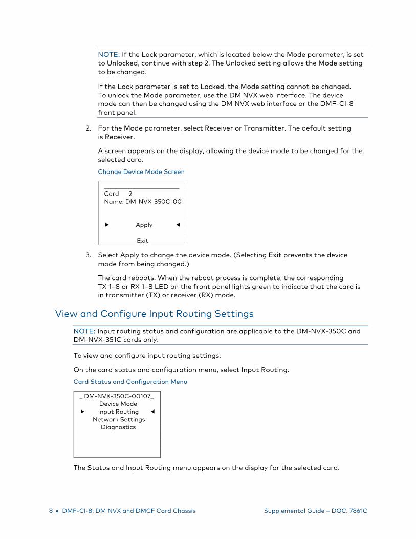
NOTE: If the Lock parameter, which is located below the Mode parameter, is set to Unlocked, continue with step 2. The Unlocked setting allows the Mode setting to be changed.
If the Lock parameter is set to Locked, the Mode setting cannot be changed. To unlock the Mode parameter, use the DM NVX web interface. The device mode can then be changed using the DM NVX web interface or the DMF-CI-8 front panel.
2. For the Mode parameter, select Receiver or Transmitter. The default setting is Receiver.
A screen appears on the display, allowing the device mode to be changed for the selected card.
Change Device Mode Screen
Card 2 Name: DM-NVX-350C-00 Apply Exit
3. Select Apply to change the device mode. (Selecting Exit prevents the device mode from being changed.)
The card reboots. When the reboot process is complete, the corresponding TX 1–8 or RX 1–8 LED on the front panel lights green to indicate that the card is in transmitter (TX) or receiver (RX) mode.
View and Configure Input Routing Settings
NOTE: Input routing status and configuration are applicable to the DM-NVX-350C and DM-NVX-351C cards only.
To view and configure input routing settings:
On the card status and configuration menu, select Input Routing.
Card Status and Configuration Menu
_ DM-NVX-350C-00107_ Device Mode Input Routing Network Settings Diagnostics
The Status and Input Routing menu appears on the display for the selected card.

Supplemental Guide – DOC. 7861C DMF-CI-8: DM NVX and DMCF Card Chassis • 9
Status and Input Routing Menu
_ DM-NVX-350C-00107_ Status Input Routing
The following sections provide information about viewing and configuring input routing settings.
View Input Routing Settings
To view the input routing settings of a card:
On the Status and Input Routing menu, select Status.
Status and Input Routing Menu
_ DM-NVX-350C-00107_ Status Input Routing
The Input Routing Status screen appears on the display for the selected card.
Sample Input Routing Status Screen
_ DM-NVX-350C-00107_ Active Video Source: None Active Audio Source: Audio follows Video
The Input Routing Status screen displays the following information:
• Active Video Source: Displays the active video source for the transmitter or the receiver as one of the following:
- None (default setting)
- Input 1
- Input 2
- Stream (receiver only)

10 • DMF-CI-8: DM NVX and DMCF Card Chassis Supplemental Guide – DOC. 7861C
• Active Audio Source: Displays the active audio source for the transmitter or the receiver as one of the following:
- Audio follows Video (default setting)
- Analog Audio
- Input 1
- Input 2
- Primary stream (receiver only)
- Secondary stream (receiver only)
Configure Input Routing Settings
To configure input routing settings for the selected card:
1. On the Status and Input Routing menu, select Input Routing.
Status and Input Routing Menu
_ DM-NVX-350C-00107_ Status Input Routing
The Input Routing menu appears on the display for the selected card.
Input Routing Menu
_ DM-NVX-350C-00107_ Input Routing Video None e Audio Audio follows Video
2. Configure input routing settings:
• Video: Select one of the following as the video source:
- None (default setting)
- Input 1
- Input 2
- Stream (receiver only)

Supplemental Guide – DOC. 7861C DMF-CI-8: DM NVX and DMCF Card Chassis • 11
Audio: Select one of the following as the audio source:
- Audio follows Video (default setting)
- Analog Audio
- Input 1
- Input 2
- Primary stream (receiver only)
- Secondary stream (receiver only)
View and Configure Network Settings To view and configure the network settings of a card:
On the card status and configuration menu, select Network Settings.
Card Status and Configuration Menu
_ DM-NVX-350C-00107_ Device Mode Input Routing Network Settings Diagnostics
The Status and IPv4 Setup menu appears on the display for the selected card.
Status and IPv4 Setup Menu
_ DM-NVX-350C-00107_ Status IPv4 Setup
The following sections provide information about viewing and configuring network settings.

12 • DMF-CI-8: DM NVX and DMCF Card Chassis Supplemental Guide – DOC. 7861C
View Network Settings
To view the network settings of a card:
On the Status and IPv4 Setup menu, select Status.
Status and IPv4 Setup Menu
_ DM-NVX-350C-00107_ Status IPv4 Setup
The Network Status screen appears on the display for the selected card.
Sample Network Status Screen
_ DM-NVX-350C-00107_ DHCP: Enabled IP: 192.168.123.123 Sub: 255.255.255.0 Gate: 192.168.123.1 MAC: 00:10:7f:7c:5e:af
The Network Status screen displays the following information:
• DHCP: Enabled or Disabled. By default, DHCP is enabled.
• IP: IPv4 address of the card
• Sub: Subnet mask address
• Gate: Gateway address
• MAC: MAC address of the card

Supplemental Guide – DOC. 7861C DMF-CI-8: DM NVX and DMCF Card Chassis • 13
Configure IPv4 Settings
To configure IPv4 settings for the selected card:
1. On the Status and IPv4 Setup menu, select IPv4 Setup.
Status and IPv4 Setup Menu
_ DM-NVX-350C-00107_ Status IPv4 Setup
The IPv4 Setup screen appears on the display for the selected card when DHCP is enabled (default setting).
IPv4 Setup Screen (DHCP Enabled)
_ DM-NVX-350C-00107_ IPv4 Setup IPv4 Enable DHCP Enable Renew No
2. Configure IPv4 settings as follows:
• IPv4: Enable
NOTE: The default setting is Enable. At the time of publication of this document, Enable is the only available selection and cannot be changed.
• DHCP: Select Enable or Disable. The default setting is Enable. If Disable is selected, refer to “Disable DHCP” on the following page.
If any change is made to DHCP settings, the changes must be applied. Refer to “Apply IPv4 DHCP Settings” on page 15.
• Renew: Select No if forcing renewal of a DHCP lease is not desired. Select Yes to force renewal of the DHCP lease. The default setting is No. If Yes is selected, refer to “Renew a DHCP Lease” on page 15.
14 • DMF-CI-8: DM NVX and DMCF Card Chassis Supplemental Guide – DOC. 7861C
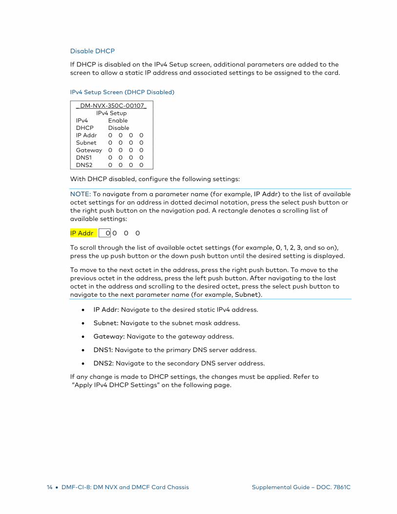
Disable DHCP
If DHCP is disabled on the IPv4 Setup screen, additional parameters are added to the screen to allow a static IP address and associated settings to be assigned to the card.
IPv4 Setup Screen (DHCP Disabled)
_ DM-NVX-350C-00107_ IPv4 Setup IPv4 Enable DHCP Disable IP Addr 0 0 0 0 Subnet 0 0 0 0 Gateway 0 0 0 0 DNS1 0 0 0 0 DNS2 0 0 0 0
With DHCP disabled, configure the following settings:
NOTE: To navigate from a parameter name (for example, IP Addr) to the list of available octet settings for an address in dotted decimal notation, press the select push button or the right push button on the navigation pad. A rectangle denotes a scrolling list of available settings:
IP Addr 190 0 0 0
To scroll through the list of available octet settings (for example, 0, 1, 2, 3, and so on), press the up push button or the down push button until the desired setting is displayed.
To move to the next octet in the address, press the right push button. To move to the previous octet in the address, press the left push button. After navigating to the last octet in the address and scrolling to the desired octet, press the select push button to navigate to the next parameter name (for example, Subnet).
• IP Addr: Navigate to the desired static IPv4 address.
• Subnet: Navigate to the subnet mask address.
• Gateway: Navigate to the gateway address.
• DNS1: Navigate to the primary DNS server address.
• DNS2: Navigate to the secondary DNS server address.
If any change is made to DHCP settings, the changes must be applied. Refer to “Apply IPv4 DHCP Settings” on the following page.

Supplemental Guide – DOC. 7861C DMF-CI-8: DM NVX and DMCF Card Chassis • 15
Apply IPv4 DHCP Settings
After changing DHCP settings, do the following:
1. Access the Update IPv4 Settings screen by pressing the HOME or the BACK push button.
NOTE: If neither the HOME nor the BACK push button is pressed, the IPv4 Setup screen automatically times out and the Update IPv4 Settings screen appears.
Update IPv4 Settings Screen
Update IPv4 Settings Card 2 Name: DM-NVX-350C-00 Apply Exit
2. Select Apply to update the IPv4 settings. (Selecting Exit prevents the IPv4 settings from being updated.)
Renew a DHCP Lease
When Renew is set to Yes on the IPv4 Setup screen, the Renew IPv4 Lease screen appears for the selected card.
Renew IPv4 Lease Screen
Renew IPv4 Lease Card 2 Name: DM-NVX-350C-00 Apply Exit
Select Apply to renew the IPv4 lease. (Selecting Exit prevents the lease from being renewed.)

16 • DMF-CI-8: DM NVX and DMCF Card Chassis Supplemental Guide – DOC. 7861C
Perform Diagnostics To perform diagnostics on a card:
On the card status and configuration menu, select Diagnostics.
Card Status and Configuration Menu
_ DM-NVX-350C-00107_ Device Mode Input Routing Network Settings Diagnostics
The Diagnostics menu appears on the display for the selected card.
Diagnostics Menu
_ DM-NVX-350C-00107_ Details Status Reset Restore
The following sections provide information about viewing and configuring card diagnostics.
View Card Details
Card details consist of the serial number and firmware version of the selected card. To view card details:
On the Diagnostics menu, select Details.
Diagnostics Menu
_ DM-NVX-350C-00107_ Details Status Reset Restore
The Card Details screen appears on the display for the selected card. A sample screen is shown on the following page.

Supplemental Guide – DOC. 7861C DMF-CI-8: DM NVX and DMCF Card Chassis • 17
Sample Card Details Screen
_ DM-NVX-350C-00107_ Serial Number: 4001F29D Firmware Version: 1.3626.00022
View Card Status
Card status consists of items such as the operating temperature of the card. To view card status:
On the Diagnostics menu, select Status.
Diagnostics Menu
_ DM-NVX-350C-00107_ Details Status Reset Restore
The Card Status screen appears on the display for the selected card.
Sample Card Status Screen
_ DM-NVX-350C-00107_ Temp: 56° C Voltages: OK Primary Image: OK Secondary Image: OK
The Card Status screen displays the following information:
• Temp: Operating temperature of the card
• Voltages: Status of the voltage condition: OK or Fail
• Primary Image: Status of the primary firmware image: OK or Fail
• Secondary Image: Status of the secondary firmware image: OK or Fail

18 • DMF-CI-8: DM NVX and DMCF Card Chassis Supplemental Guide – DOC. 7861C
Reset a Card
Resetting a card causes the card to reboot. To reset a card:
1. On the Diagnostics menu, select Reset.
Diagnostics Menu
_ DM-NVX-350C-00107_ Details Status Reset Restore
The Reset screen appears on the display for the selected card.
Reset Screen
Reset a Card: 2 Name: DM-NVX-350C-00 Apply Exit
2. Select Apply to reset the card. (Selecting Exit prevents the card from being reset and returns the display to the Diagnostics menu.)
NOTE: While the card is being reset, the corresponding green Card Slot Status LED on the front panel of the DMF-CI-8 turns off. The LED turns on again when the card is reset.

Supplemental Guide – DOC. 7861C DMF-CI-8: DM NVX and DMCF Card Chassis • 19
Restore a Card to the Factory Default Settings
The factory default settings of a card can be restored on a card-by-card basis.
NOTE: To restore all cards on a global basis to the factory default settings, refer to “Restore Factory Default Settings” on page 24.
To restore a card to the factory default settings:
1. On the Diagnostics menu, select Restore.
Diagnostics Menu
_ DM-NVX-350C-00107_ Details Status Reset Restore
The Restore screen appears on the display for the selected card.
Restore Screen
Restore _ Card: 2 Name: DM-NVX-350C-00 Apply Exit
2. Select Apply to restore the factory default settings. (Selecting Exit prevents the factory default settings from being restored and returns the display to the Diagnostics menu.)
20 • DMF-CI-8: DM NVX and DMCF Card Chassis Supplemental Guide – DOC. 7861C
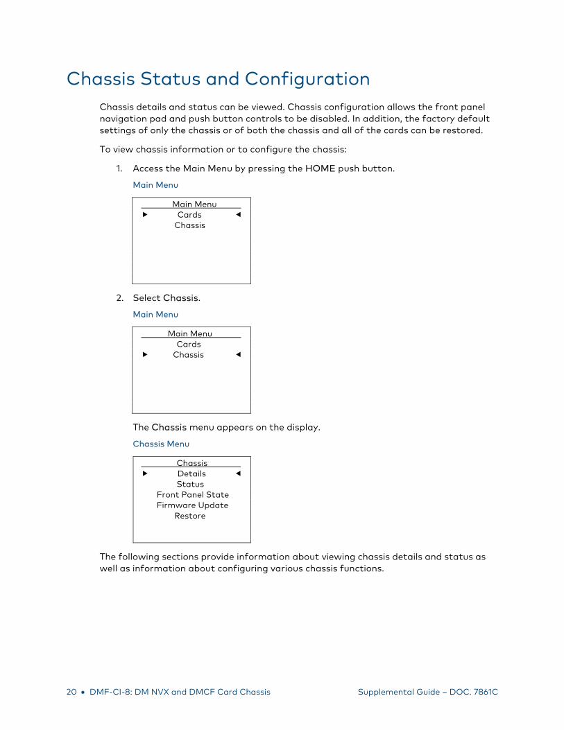
Chassis Status and Configuration Chassis details and status can be viewed. Chassis configuration allows the front panel navigation pad and push button controls to be disabled. In addition, the factory default settings of only the chassis or of both the chassis and all of the cards can be restored.
To view chassis information or to configure the chassis:
1. Access the Main Menu by pressing the HOME push button.
Main Menu
Main Menu a Cards Chassis
2. Select Chassis.
Main Menu
Main Menu a Cards Chassis
The Chassis menu appears on the display.
Chassis Menu
Chassis Details Status Front Panel State Firmware Update Restore
The following sections provide information about viewing chassis details and status as well as information about configuring various chassis functions.

Supplemental Guide – DOC. 7861C DMF-CI-8: DM NVX and DMCF Card Chassis • 21
View Chassis Details
Chassis details consist of the serial number and firmware version of the chassis. To view chassis details:
On the Chassis menu, select Details.
Chassis Menu
Chassis Details Status Front Panel State Firmware Update Restore
The Details screen appears on the display showing the serial number and firmware version of the chassis.
Sample Chassis Details Screen
Details a Serial Number: 00F626E9 Firmware Version: 1.3054.60
View Chassis Status
Chassis status consists of the operating temperature and the RPM of each fan in the chassis. To view the chassis status:
On the Chassis menu, select Status.
Chassis Menu
Chassis Details Status Front Panel State Firmware Update Restore
The Status screen appears on the display showing the operating temperature of the chassis and the RPM of each fan in the chassis. A sample screen is shown on the following page.

22 • DMF-CI-8: DM NVX and DMCF Card Chassis Supplemental Guide – DOC. 7861C
Sample Chassis Status Screen
Status a Temp: 25° C Fan 1: 1855 RPM Fan 2: 1832 RPM Fan 3: 1891 RPM
Configure the Front Panel
The navigation pad and the HOME and BACK push button controls on the front panel can be disabled.
To disable the front panel controls:
1. On the Chassis menu, select Front Panel State.
Chassis Menu
Chassis Details Status Front Panel State Firmware Update Restore
The Disable Front Panel screen appears on the display.
Disable Front Panel Screen
Disable Front Panel a This will disable all the hard buttons on the front panel. Apply Exit
2. Select Apply to disable the front panel controls. The display returns to the general information screen. (Selecting Exit prevents the front panel buttons from being disabled and returns the display to the Chassis menu.)

Supplemental Guide – DOC. 7861C DMF-CI-8: DM NVX and DMCF Card Chassis • 23
To enable the front panel controls, do either of the following:
• Press the select push button on the navigation pad, the HOME push button, and the BACK push button simultaneously.
• Use Text Console in the Crestron Toolbox software and enter the following command:
lcd l off
where l is the lowercase letter L and off disables the lock on the front panel controls. (Entering lcd l on enables the lock on the front panel controls and therefore disables the controls.)
Update Firmware
The latest firmware file can be downloaded from the Crestron website after logging in as an authorized user. The firmware file is a .upg file, which is included in a .zip file. The .zip file also includes an .html file, which links to the product release notes on the Crestron website.
To upgrade firmware:
1. Extract the *.upg file from the *.zip file (the * represents the respective filename).
2. Copy the *.upg file to the root directory of a USB flash drive.
NOTE: The USB flash drive must use FAT32.
NOTE: Ensure that the latest firmware file (*.upg) is the only firmware file in the root directory.
3. On the Chassis menu, select Firmware Update.
Chassis Menu
Chassis Details Status Front Panel State Firmware Update Restore
The Chassis Firmware screen appears on the display.

24 • DMF-CI-8: DM NVX and DMCF Card Chassis Supplemental Guide – DOC. 7861C
Chassis Firmware Screen
Chassis Firmware e Please insert USB mass storage device to start.
Apply Exit
4. Insert a USB flash drive into the USB Type A port, which is located on the front panel of the DMF-CI-8.
5. Select Apply. The Crestron logo appears on the display while the firmware is being updated. When the firmware update process is complete, the display returns to the general information screen.
6. Remove the USB flash drive from the USB Type A port.
Restore Factory Default Settings
Factory default settings can be restored using either of the following options:
• Chassis only
• Chassis and all cards installed in the chassis
NOTE: To restore the factory default settings of cards on an individual basis, refer to “Restore a Card to the Factory Default Settings” on page 19.
To restore the factory default settings of the chassis only or of the chassis and all installed cards:
1. On the Chassis menu, select Restore.
Chassis Menu
Chassis Details Status Front Panel State Firmware Update Restore
The Restore menu appears on the display.

Supplemental Guide – DOC. 7861C DMF-CI-8: DM NVX and DMCF Card Chassis • 25
Restore Menu
Restore a Chassis Only Chassis and Cards
2. Do either of the following:
To restore the factory default settings of the chassis only, select Chassis Only. The Restore Chassis screen appears on the display. Continue with step 3.
To restore the factory default settings of the chassis as well as all installed cards, select Chassis and Cards. The Restore All Devices screen appears on the display. To proceed, skip step 3 and continue with step 4.
3. (For restoral of chassis default settings only) On the Restore Chassis screen, select Apply.
Restore Chassis Screen
Restore Chassis a This will restore the chassis to its default values. Apply Exit
The factory default settings of the chassis are restored. The display returns to the general information screen.
4. (For restoral of chassis and card default settings) On the Restore All Devices screen, select Apply.
Restore All Devices Screen
Restore All Devices a This will restore the chassis and all cards to their default. Apply Exit
The factory default settings of the chassis and all installed cards are restored. The display returns to the general information screen.

Crestron Electronics, Inc. Supplemental Guide – DOC. 7861C 15 Volvo Drive Rockleigh, NJ 07647 (2047624) Tel: 888.CRESTRON 05.18 Fax: 201.767.7576 Specifications subject to www.crestron.com change without notice.


![Video Editing and Production Checklist [digitalmedia]](https://img.pdfslide.net/doc/110x75/5565a7ded8b42a4c6f8b4592/video-editing-and-production-checklist-digitalmedia.jpg)
![Games and Gamification - Part Two [digitalmedia]](https://img.pdfslide.net/doc/110x75/54c8015b4a7959335d8b45f8/games-and-gamification-part-two-digitalmedia.jpg)
![Video Shooting Techniques [digitalmedia]](https://img.pdfslide.net/doc/110x75/5464739aaf7959f2058b67bd/video-shooting-techniques-digitalmedia.jpg)


![Fundamentals of Storytelling [digitalmedia]](https://img.pdfslide.net/doc/110x75/5454fa61af7959e56c8b4577/fundamentals-of-storytelling-digitalmedia.jpg)


![Digitalmedia Outsource Solution [DOS]](https://img.pdfslide.net/doc/110x75/557cf8b7d8b42a98158b4aec/digitalmedia-outsource-solution-dos.jpg)