Embed Size (px)
Citation preview
HighPROTEC-2 MRA4-2
• DNP 3.0• Multiple Communication
with one device
• ANSI Menu structure
• Page Editor
• New front plate with USB
• IEC61850 with LC interface
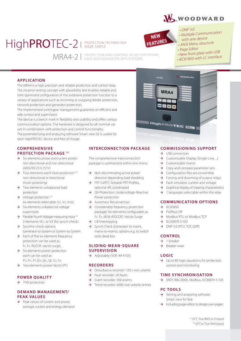
Applic Ation The MRA4 is a high precision and reliable protection and control relay. The intuitive setting concept with plausibility test enables reliable and time optimized configuration of the extensive protection function to a variety of applications such as incoming or outgoing feeder protection, network protection and generator protection.The implemented switchgear management guaranties an efficient and safe control and supervision. The device is a bench mark in flexibility and usability and offers various communication options. The hardware is designed for all nominal val-ues in combination with protection and control functionality. The parameterizing and analyzing software Smart view SE is usable for each HighPROTEC device and free of charge.
co m pr e h e nsiv e protec ti o n pAck Ag e (1)
Six elements phase overcurrent protec- tion directional and non-directional (ANSI/IEC/51C/51V)
Four elements earth fault protection (2) non-directional or directional (multi-polarising)
Two elements unbalanced load protection
Voltage protection (2) six elements selectable: V<, V>, V<(t)
Six elements unbalanced voltage supervision
Flexible Fourth Voltage measuring input (2) 2 elements VE> or VX (for synch-check)
Synchro-check options Generator-to-System or System-to-System
Each of the six elements frequency protection can be used as: f<, f>, ROCOF, vector surge...
Six elements power protection each can be used as: P>, P<, Pr, Q>, Q<, Qr, S>, S<
Two elements power factor (PF)
powe r quAlit y THD protection
D e m An D m AnAg e m e n t/ pe Ak vAlu e s
Peak values of current and power, average current and energy demand
i n te rco n n ec ti o n pAck Ag e
The comprehensive interconnection package is summarized within one menu:
Non-discriminating active power direction depending load shedding FRT (LVRT): Settable FRT-Profiles, optional AR coordinated QV-Protection: Undervoltage-Reactive Power protection
Automatic Reconnection Considerably frequency protection package: Six elements configurable as f<, f>, df/dt (ROCOF), Vector Surge CB-Intertripping Synch Check (Generator to mains, mains-to-mains), options e.g. to switch onto dead bus
sli D i n g - m e An -squAr e su pe rv isi o n
Adjustable (VDE-AR 4105)
r eco r D e r s Disturbance recorder: 120 s non volatile Fault recorder: 20 faults Event recorder: 300 events Trend recorder: 4000 non volatile entries
co m m issi o n i n g su ppo r t USB connection Customizable Display (Single-Line, ...) Customizable Inserts Copy and compare parameter sets Configuration files are convertible Forcing and disarming of output relays Fault simulator: current and voltage Graphical display of tripping characteristics 7 languages selectable within the relay
co m mu n i c Ati o n o p ti o ns IEC61850 Profibus DP Modbus RTU or Modbus TCP IEC60870-5-103 DNP 3.0 (RTU, TCP, UDP)
co n tro l 1 breaker Breaker wear
lo g i c Up to 80 logic equations for protection,
control and monitoring
ti m e sy n ch ro n isAti o n SNTP, IRIG-B00X, Modbus, IEC60870-5-103
pc to o l s Setting and analyzing software
Smart view for free Including page editor to design own pages
(1) DFT, True RMS or I2 based(2) DFT or True RMS based
PROTECTION AND CONTROL RELAy FOR FEEDER,GRID AND GENERATOR APPLICATIONS
PROTECTION TECHNOLOGy MADE SIMPLE
w w w . w o o d w a r d . c o m
MRA4-2 PROTECTION AND CONTROL RELAy FOR FEEDER,GRID AND GENERATOR APPLICATIONS
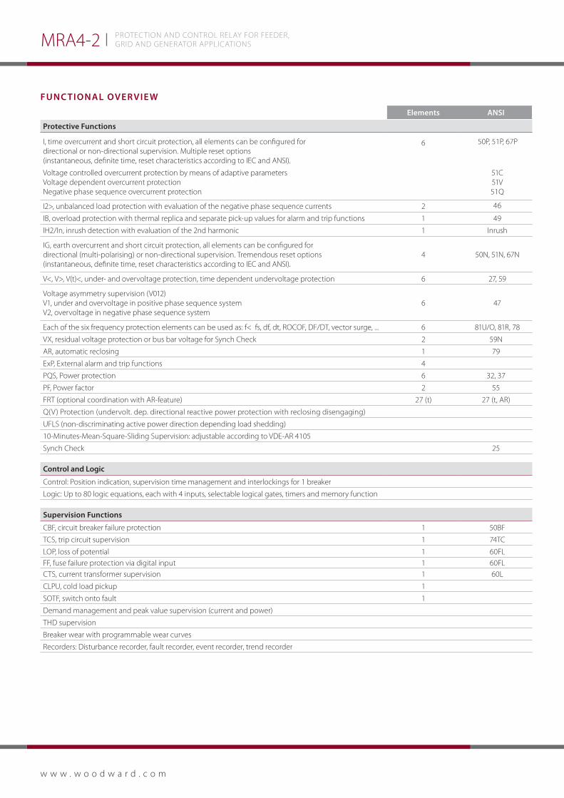
Func tionAl over vie w
elements Ansi
protective Functions
I, time overcurrent and short circuit protection, all elements can be configured for directional or non-directional supervision. Multiple reset options (instantaneous, definite time, reset characteristics according to IEC and ANSI).
Voltage controlled overcurrent protection by means of adaptive parametersVoltage dependent overcurrent protectionNegative phase sequence overcurrent protection
6
50P, 51P, 67P
51C51V51Q
I2>, unbalanced load protection with evaluation of the negative phase sequence currents 2 46
IB, overload protection with thermal replica and separate pick-up values for alarm and trip functions 1 49
IH2/In, inrush detection with evaluation of the 2nd harmonic 1 Inrush
IG, earth overcurrent and short circuit protection, all elements can be configured for directional (multi-polarising) or non-directional supervision. Tremendous reset options (instantaneous, definite time, reset characteristics according to IEC and ANSI).
4 50N, 51N, 67N
V<, V>, V(t)<, under- and overvoltage protection, time dependent undervoltage protection 6 27, 59
Voltage asymmetry supervision (V012) V1, under and overvoltage in positive phase sequence system V2, overvoltage in negative phase sequence system
6 47
Each of the six frequency protection elements can be used as: f< fs, df, dt, ROCOF, DF/DT, vector surge, ... 6 81U/O, 81R, 78
VX, residual voltage protection or bus bar voltage for Synch Check 2 59N
AR, automatic reclosing 1 79
ExP, External alarm and trip functions 4
PQS, Power protection 6 32, 37
PF, Power factor 2 55
FRT (optional coordination with AR-feature) 27 (t) 27 (t, AR)
Q(V) Protection (undervolt. dep. directional reactive power protection with reclosing disengaging)
UFLS (non-discriminating active power direction depending load shedding)
10-Minutes-Mean-Square-Sliding Supervision: adjustable according to VDE-AR 4105
Synch Check 25
control and logic
Control: Position indication, supervision time management and interlockings for 1 breaker
Logic: Up to 80 logic equations, each with 4 inputs, selectable logical gates, timers and memory function
supervision Functions
CBF, circuit breaker failure protection 1 50BF
TCS, trip circuit supervision 1 74TC
LOP, loss of potential 1 60FLFF, fuse failure protection via digital input 1 60FLCTS, current transformer supervision 1 60L
CLPU, cold load pickup 1
SOTF, switch onto fault 1
Demand management and peak value supervision (current and power)
THD supervision
Breaker wear with programmable wear curves
Recorders: Disturbance recorder, fault recorder, event recorder, trend recorder
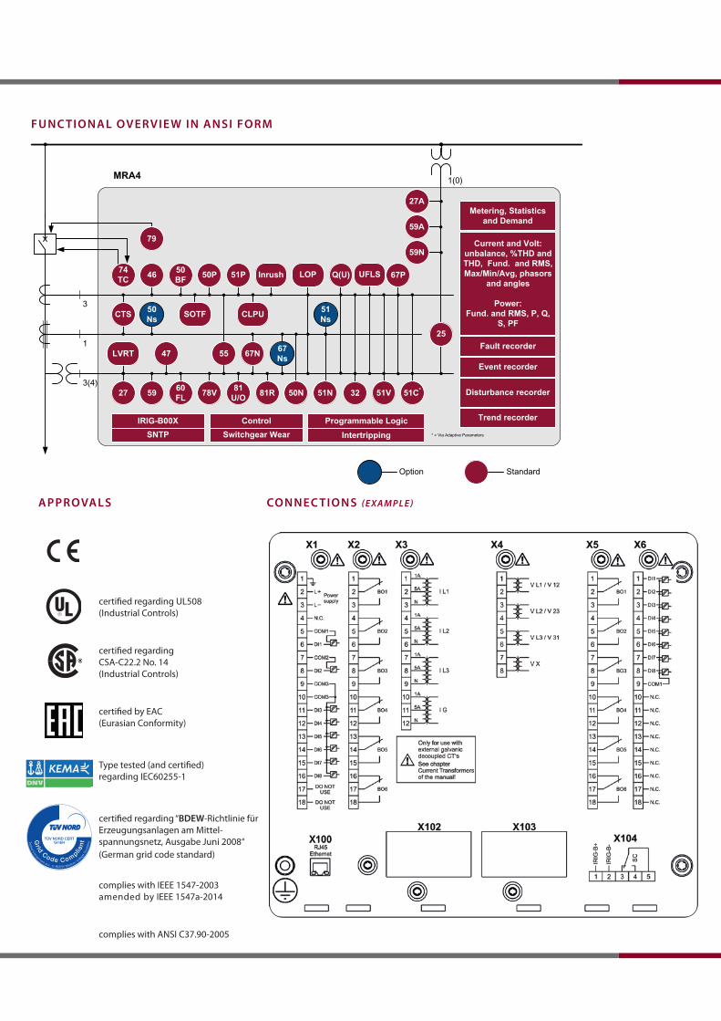
certified regarding UL508 (Industrial Controls)
certified regarding CSA-C22.2 No. 14 (Industrial Controls)
certified by EAC(Eurasian Conformity)
Type tested (and certified) regarding IEC60255-1
certified regarding “BDew-Richtlinie für Erzeugungsanlagen am Mittel-spannungsnetz, Ausgabe Juni 2008“
complies with IEEE 1547-2003amended by IEEE 1547a-2014
complies with ANSI C37.90-2005
(German grid code standard)
MRA4
*
* = Via Adaptive Parameters
74TC
50BF 50P 51P46
81R81U/O78V60
FL5927 50N 51N 51V
67N
51C*
SOTF CLPU
Fault recorder
Event recorder
Disturbance recorder
Current and Volt: unbalance, %THD and THD, Fund. and RMS, Max/Min/Avg, phasors
and angles
Power:Fund. and RMS, P, Q,
S, PF
Metering, Statistics and Demand
Inrush
79
Q(U)
CTS
47
Standard
55
LOP
32
25
Programmable LogicIRIG-B00X Trend recorder
Option
51Ns
67Ns
50Ns
SNTP Switchgear WearControl
LVRT
Intertripping
59N
59A
27A
67PUFLS
Func tionAl over vie w in Ansi Form
ApprovAls connec tions (ExamplE)

MRA4-2 PROTECTION AND CONTROL RELAy FOR FEEDER,GRID AND GENERATOR APPLICATIONS
orDer Form mr A4-2
current inputs 4 (1 A and 5 A) with automatic CT Disconnectvoltage inputs 4 (0– 800 V)Digital inputs Switching thresholds adjustable via softwarepower supply Wide range power supply 24 V
DC - 270 V
DC / 48 V
AC - 230 V
AC (-20/+10%)
terminals All terminals plug typetype of enclosure IP54Dimensions of housing 19“ flush mounting: 212.7 mm x 173 mm x 208 mm (w x h x D) 8.374 in. x 6.811 in. x 8.189 in. Door mounting 212.7 mm x 183 mm x 208 mm 8.374 in. x 7.205 in. x 8.189 in. weight (max. components) approx. 4.7 kg / 10.36 lb
contAc t:
north & central America
Phone: +1 970 962 7331
E-mail: [email protected]
south America
Phone: +55 19 3708 4800
E-mail: [email protected]
europe
Phone: +49 2152 145 331
E-mail: [email protected]
middle east & Africa
Phone: +971 2 6275185
E-mail: [email protected]
russia
Phone: +7 812 319 3007
E-mail: [email protected]
china
Phone: +86 512 8818 5515
E-mail: [email protected]
india
Phone: +91 124 4399 500
E-mail: [email protected]
AseAn & oceania
Phone: +49 711 78954 510
E-mail: [email protected]
© Woodward
All Rights Reserved | 09/2015 DO
K-FL
y-M
RA4-
2E_R
ev.E
|
Sub
ject
to a
ltera
tions
, err
ors
exce
pted
.
Directional Feeder protection MRA4 -2
Version 2 with USB, enhanced communication and user options
Digitalinputs
Binaryoutput relays housing large
display8 7 B2 - A
16 13 B2 - D
hardware variant 2Phase Current 5 A/1 A, Ground Current 5 A/1 A 0
Phase Current 5 A/1 A, Sensitive Ground Current 5 A/1 A 1 housing and mountingDoor mounting ADoor mounting 19” (flush mounting) Bcommunication protocolWithout protocol A*
Modbus RTU, IEC60870-5-103, DNP3.0 RTU | RS485/terminals B*
Modbus TCP, DNP3.0 TCP/UDP | Ethernet 100 MB/RJ45 C* Profibus-DP | optic fiber/ST-connector D*
Profibus-DP | RS485/D-SUB E*
Modbus RTU, IEC60870-5-103, DNP3.0 RTU | optic fiber/ST-connector F*
Modbus RTU, IEC60870-5-103, DNP3.0 RTU | RS485/D-SUB G*
IEC61850, Modbus TCP, DNP3.0 TCP/UDP | Ethernet 100MB/RJ45 H* IEC60870-5-103, Modbus RTU, DNP3.0 RTU | RS485/terminals Modbus TCP, DNP3.0 TCP/UDP | Ethernet 100 MB/RJ45
I*
IEC61850, Modbus TCP, DNP3.0 TCP/UDP | Optical Ethernet 100MB/LC duplex connector K*Modbus TCP, DNP3.0 TCP/UDP | Optical Ethernet 100MB/LC duplex connector L* harsh environment option
None A
Conformal Coating BAvailable menu languages (in every device)
Standard English/German/Spanish/Russian/Polish/Portuguese/French
* Within every communication option only one communication protocol is usable. Smart view can be used in parallel via the Ethernet interface (RJ45).
The parameterizing- and disturbance analyzing software Smart view is included in the delivery of HighPROTEC devices.
For m
ore
info
rmat
ion
plea
se c
onta
ct: