Embed Size (px)
Citation preview
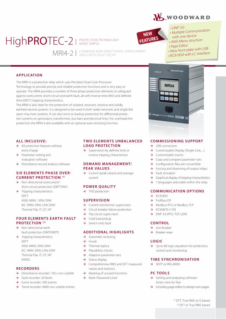
HighPROTEC-2 MRI4-2
• DNP 3.0• Multiple Communication
with one device
• ANSI Menu structure
• Page Editor
• New front plate with USB
• IEC61850 with LC interface
Applic Ation
The MRI4 is a protection relay which uses the latest Dual-Core-Processor Technology to provide precise and reliable protective functions and is very easy to operate. The MRI4 provides a number of three phase protection elements to safeguard against overcurrent, short-circuit and earth fault, all with inverse time (INV) and definite time (DEFT) tripping characteristics. The MRI4 is also ideal for the protection of isolated, resonant, resistive and solidly earthed neutral systems. It is designed to be used in both radial networks and single fed open ring main systems. It can also serve as backup protection for differential protec-tion systems on generators, transformers, bus bars and electrical lines. For overhead line protection the MRI4 is also available with an optional auto reclosing function.
All i n clusiv e: All protection features without
extra charge Parameter setting and
evaluation software Disturbance record analysis software
six e le m e n t s phA se ov e r- cu r r e n t protec ti o n (1)
Non-directional overcurrent/ short-circuit protection (DEFT/INV)
Tripping characteristics: DEFT ANSI: MINV , VINV, EINV IEC: NINV, VINV, LINV, EINV Thermal Flat, IT, I2T, I4T Fo u r e le m e n t s e Ar th FAu lt protec ti o n (2)
Non-directional earth fault protection (DMT/IMDT)
Tripping characteristics: DEFT ANSI: MINV, VINV, EINV IEC: NINV, VINV, LINV, EINV Thermal Flat, IT, I2T, I4T RXIDG
r eco r d e r s Disturbance recorder: 120 s non volatile Fault recorder: 20 faults Event recorder: 300 events Trend recorder: 4000 non volatile entries
t wo e le m e n t s u n bAl An ce d loAd protec ti o n
Supervision by definite time or inverse tripping characteristic
d e m An d m AnAg e m e n t/ pe Ak vAlu e s
Current (peak values) and average current
powe r quAlit y THD protection
su pe rv isi o n Current transformer supervision Circuit breaker failure protection Trip circuit supervision Cold load pickup Switch onto fault
Ad d iti o nAl h i g h li g h t s Automatic reclosing Inrush Thermal replica Plausibility checks Adaptive parameter sets Status display Comprehensive RMS and DFT measured
values and statistics Masking of unused functions
Multi-Password-Level
co m m issi o n i n g su ppo r t USB connection Customizable Display (Single-Line, ...) Customizable Inserts Copy and compare parameter sets Configuration files are convertible Forcing and disarming of output relays Fault simulator Graphical display of tripping characteristics 7 languages selectable within the relay
co m mu n i c Ati o n o p ti o ns IEC61850 Profibus DP Modbus RTU or Modbus TCP IEC60870-5-103 DNP 3.0 (RTU, TCP, UDP)
co n tro l one breaker Breaker wear
lo g i c Up to 80 logic equations for protection,
control and monitoring
ti m e sy n ch ro n isAti o n SNTP or IRIG-B00X
pc to o l s Setting and analyzing software
Smart view for free Including page editor to design own pages
(1) DFT, True RMS or I2 based(2) DFT or True RMS based
CoMBINED NoN-DIRECTIoNAL oVERCURRENT AND EARTH-FAULT RELAy
PRoTECTIoN TECHNoLoGy MADE SIMPLE

w w w . w o o d w a r d . c o m
MRI4-2 CoMBINED NoN-DIRECTIoNAL oVERCURRENT AND EARTH-FAULT RELAy
Func tionAl over vie w
elements Ansi
protective Functions
I, time overcurrent and short circuit protection, multiple reset options (instantaneous, definite time, reset characteristics according to IEC and ANSI)
6 50P, 51P, 67P
Negative phase sequence overcurrent protection 51Q
I2>, unbalanced load protection with evaluation of the negative phase sequence currents 2 46ThA, overload protection with thermal replica and separate pick-up values for alarm and trip functions 1 49
IH2/In, inrush detection with evaluation of the 2nd harmonic 1 Inrush
IG, earth overcurrent and short circuit protection 4 50N, 51N
AR, automatic reclosing 1 79
ExP, External alarm and trip functions 4
control and logic
Control, Position indication, supervision time management and interlockings for 1 breaker
Logic: Up to 80 logic equations, each with 4 inputs, selectable logical gates, timers and memory function
supervision Functions
CBF, circuit breaker failure protection 1 50BF
TCS, trip circuit supervision 1 74TC
CTS, current transformer supervision 1 60L
CLPU, cold load pickup 1
SoTF, switch onto fault 1
Demand management and peak value supervision
THD supervision
Breaker wear with programmable wear curves
Recorders: Disturbance recorder, fault recorder, event recorder, trend recorder
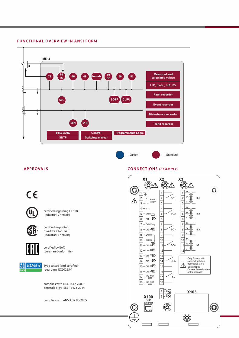
certified regarding UL508 (Industrial Controls)
certified regarding CSA-C22.2 No. 14 (Industrial Controls)
certified by EAC(Eurasian Conformity)
Type tested (and certified) regarding IEC60255-1
complies with IEEE 1547-2003amended by IEEE 1547a-2014
complies with ANSI C37.90-2005
50BF49 51504679
3
1
Inrush
50N 51N
MRI4
74TC
Fault recorder
Event recorder
Disturbance recorder
Measured and calculated values
I, IE, theta , IH2 , I2>
60L SOTF CLPU
Programmable LogicIRIG-B00X
Trend recorder
SNTP Switchgear WearControl
StandardOption
Func tionAl over vie w in Ansi Form
ApprovAls connec tions (ExamplE)
MRI4-2 CoMBINED NoN-DIRECTIoNAL oVERCURRENT AND EARTH-FAULT RELAy
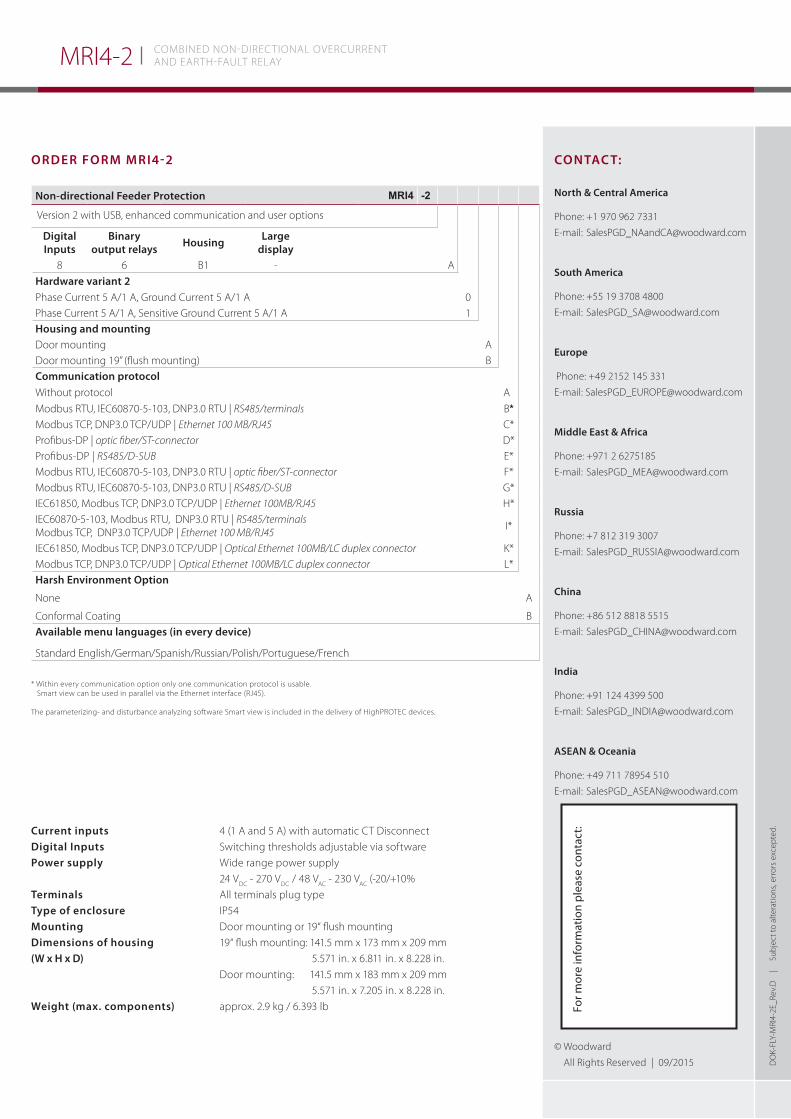
order Form mri4-2
current inputs 4 (1 A and 5 A) with automatic CT Disconnectdigital inputs Switching thresholds adjustable via softwarepower supply Wide range power supply 24 V
DC - 270 V
DC / 48 V
AC - 230 V
AC (-20/+10%
terminals All terminals plug typetype of enclosure IP54mounting Door mounting or 19“ flush mountingdimensions of housing 19“ flush mounting: 141.5 mm x 173 mm x 209 mm(w x h x d) 5.571 in. x 6.811 in. x 8.228 in. Door mounting: 141.5 mm x 183 mm x 209 mm 5.571 in. x 7.205 in. x 8.228 in. weight (max. components) approx. 2.9 kg / 6.393 lb
contAc t:
north & central America
Phone: +1 970 962 7331
E-mail: [email protected]
south America
Phone: +55 19 3708 4800
E-mail: [email protected]
europe
Phone: +49 2152 145 331
E-mail: [email protected]
middle east & Africa
Phone: +971 2 6275185
E-mail: [email protected]
russia
Phone: +7 812 319 3007
E-mail: [email protected]
china
Phone: +86 512 8818 5515
E-mail: [email protected]
india
Phone: +91 124 4399 500
E-mail: [email protected]
AseAn & oceania
Phone: +49 711 78954 510
E-mail: [email protected]
© Woodward
All Rights Reserved | 09/2015 Do
K-FL
y-M
RI4-
2E_R
ev.D
|
S
ubje
ct to
alte
ratio
ns, e
rror
s ex
cept
ed.
non-directional Feeder protection MRI4 -2
Version 2 with USB, enhanced communication and user options
digitalinputs
binaryoutput relays housing large
display8 6 B1 - A
hardware variant 2Phase Current 5 A/1 A, Ground Current 5 A/1 A 0
Phase Current 5 A/1 A, Sensitive Ground Current 5 A/1 A 1 housing and mountingDoor mounting ADoor mounting 19” (flush mounting) Bcommunication protocolWithout protocol A*
Modbus RTU, IEC60870-5-103, DNP3.0 RTU | RS485/terminals B*
Modbus TCP, DNP3.0 TCP/UDP | Ethernet 100 MB/RJ45 C* Profibus-DP | optic fiber/ST-connector D*
Profibus-DP | RS485/D-SUB E*
Modbus RTU, IEC60870-5-103, DNP3.0 RTU | optic fiber/ST-connector F*
Modbus RTU, IEC60870-5-103, DNP3.0 RTU | RS485/D-SUB G*
IEC61850, Modbus TCP, DNP3.0 TCP/UDP | Ethernet 100MB/RJ45 H* IEC60870-5-103, Modbus RTU, DNP3.0 RTU | RS485/terminals Modbus TCP, DNP3.0 TCP/UDP | Ethernet 100 MB/RJ45
I*
IEC61850, Modbus TCP, DNP3.0 TCP/UDP | Optical Ethernet 100MB/LC duplex connector K*Modbus TCP, DNP3.0 TCP/UDP | Optical Ethernet 100MB/LC duplex connector L* harsh environment option
None A
Conformal Coating BAvailable menu languages (in every device)
Standard English/German/Spanish/Russian/Polish/Portuguese/French
* Within every communication option only one communication protocol is usable. Smart view can be used in parallel via the Ethernet interface (RJ45).
The parameterizing- and disturbance analyzing software Smart view is included in the delivery of HighPRoTEC devices.
For m
ore
info
rmat
ion
plea
se c
onta
ct: