Embed Size (px)
Citation preview

8/7/2019 DNV BOP report - Vol 2 (2)
http://slidepdf.com/reader/full/dnv-bop-report-vol-2-2 1/350
The view, opinions, and/or findings contained in this report are those of the author(s) and should
not be construed as an official government position, policy or decision, unless so designated byother documentation.
DET NORSKE VERITAS
Final Report
forUNITED STATES DEPARTMENT
OF THE INTERIOR BUREAU OF OCEAN ENERGY MANAGEMENT,
REGULATION, AND ENFORCEMENT
WASHINGTON, DC 20240
FORENSIC EXAMINATION OF DEEPWATER
HORIZON BLOWOUT PREVENTER CONTRACT AWARD NO. M10PX00335
VOLUME II APPENDICES
Report No. EP030842
20 March 2011
8/7/2019 DNV BOP report - Vol 2 (2)
http://slidepdf.com/reader/full/dnv-bop-report-vol-2-2 2/350
DET NORSKE VERITAS United States Department of the Interior, Bureau of Ocean EnergyManagement, Regulation, and EnforcementForensic Examination of Deepwater Horizon Blowout Preventer
Volume I Main Report
EP030842
20 March 2011 ii
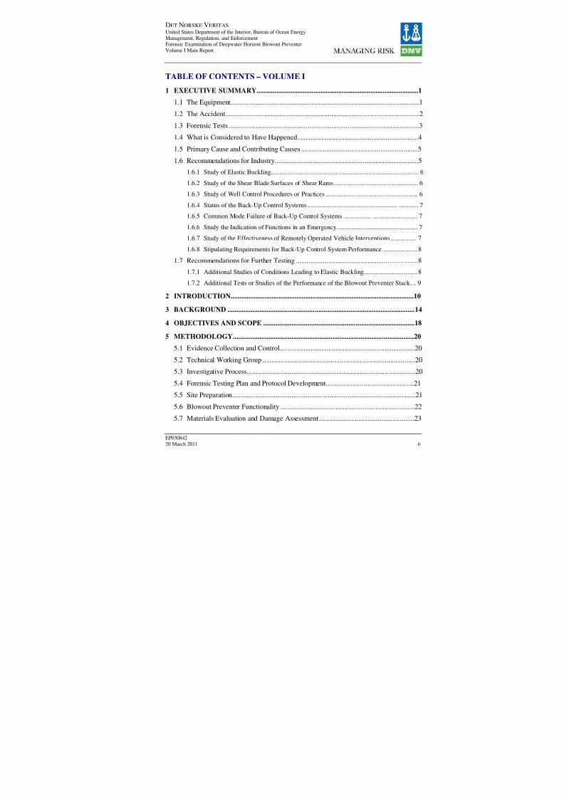
TABLE OF CONTENTS – VOLUME I
1 EXECUTIVE SUMMARY...........................................................................................1
1.1 The Equipment.........................................................................................................1
1.2 The Accident............................................................................................................2
1.3 Forensic Tests ..........................................................................................................3
1.4 What is Considered to Have Happened ...................................................................4
1.5 Primary Cause and Contributing Causes .................................................................5
1.6 Recommendations for Industry................................................................................5
1.6.1 Study of Elastic Buckling......................................................................................... 6
1.6.2 Study of the Shear Blade Surfaces of Shear Rams................................................... 6
1.6.3 Study of Well Control Procedures or Practices ........................................................ 6
1.6.4 Status of the Back-Up Control Systems ................................................................... 7
1.6.5 Common Mode Failure of Back-Up Control Systems ............................................. 7
1.6.6 Study the Indication of Functions in an Emergency................................................. 7
1.6.7 Study of the Effectiveness of Remotely Operated Vehicle Interventions ................ 7
1.6.8 Stipulating Requirements for Back-Up Control System Performance ..................... 8
1.7 Recommendations for Further Testing ....................................................................8
1.7.1 Additional Studies of Conditions Leading to Elastic Buckling................................ 8
1.7.2 Additional Tests or Studies of the Performance of the Blowout Preventer Stack.... 9
2 INTRODUCTION.......................................................................................................10
3 BACKGROUND .........................................................................................................14
4 OBJECTIVES AND SCOPE .....................................................................................18
5 METHODOLOGY......................................................................................................20
5.1 Evidence Collection and Control...........................................................................20
5.2 Technical Working Group .....................................................................................205.3 Investigative Process..............................................................................................20
5.4 Forensic Testing Plan and Protocol Development.................................................21
5.5 Site Preparation......................................................................................................21
5.6 Blowout Preventer Functionality ...........................................................................22
5.7 Materials Evaluation and Damage Assessment.....................................................23
8/7/2019 DNV BOP report - Vol 2 (2)
http://slidepdf.com/reader/full/dnv-bop-report-vol-2-2 3/350
DET NORSKE VERITAS United States Department of the Interior, Bureau of Ocean EnergyManagement, Regulation, and EnforcementForensic Examination of Deepwater Horizon Blowout Preventer
Volume I Main Report
EP030842
20 March 2011 iii
5.8 Document Review..................................................................................................24
5.9 Remotely Operated Vehicle Intervention Operations Review...............................245.10 Failure Cause Analysis ..........................................................................................25
6 FINDINGS ...................................................................................................................26
6.1 Blowout Preventer Function Testing .....................................................................26
6.1.1 Video and Photographic Documentation................................................................ 26
6.1.2 Visual Examination................................................................................................ 26
6.1.3 Fluid Collection and Analysis ................................................................................ 27
6.1.4 Drill Pipe Removal................................................................................................. 28
6.1.5 ST Locks................................................................................................................. 30 6.1.6 Lower Choke and Kill Valves ................................................................................ 31
6.1.7 Functioning and Removal of Ram Blocks.............................................................. 32
6.1.8 AMF/Deadman and Autoshear Testing – Hydraulic Circuits ................................ 34
6.1.9 Remotely Operated Vehicle Panel Testing............................................................. 40
6.1.10 Solenoid 103 Bench Testing................................................................................... 41
6.1.11 Solenoid 3A Bench Testing.................................................................................... 42
6.1.12 Blue and Yellow Pod Battery Voltage and Load Testing ...................................... 42
6.1.13 Blue and Yellow Pod Function Testing.................................................................. 43 6.2 Materials Evaluation and Damage Assessment.....................................................50
6.2.2 Three Dimensional Laser Scanning of Ram Blocks............................................... 73
6.2.3 Visual Examination of Drill Pipe ........................................................................... 78
6.2.4 Matching Drill Pipe Segments................................................................................ 93
6.2.5 Damage on Drill Pipe Segment in Variable Bore Rams ...................................... 107
6.2.6 Damage to the Wellbore....................................................................................... 108
6.2.7 Other Evidence Assessment ................................................................................. 110
6.2.8 Metallurgical, Mechanical, Chemical Property Assessment................................ 112
6.3 Document Review................................................................................................131
6.4 Remotely Operated Vehicle Intervention Efforts ................................................136
6.4.1 Activation of the Blind Shear Rams..................................................................... 137
6.4.2 Repair Efforts ....................................................................................................... 144
6.5 Modeling..............................................................................................................147

8/7/2019 DNV BOP report - Vol 2 (2)
http://slidepdf.com/reader/full/dnv-bop-report-vol-2-2 4/350
DET NORSKE VERITAS United States Department of the Interior, Bureau of Ocean EnergyManagement, Regulation, and EnforcementForensic Examination of Deepwater Horizon Blowout Preventer
Volume I Main Report
EP030842
20 March 2011 iv
6.5.1 Buckling Model.................................................................................................... 148
6.5.2 Buckling Considerations ...................................................................................... 151
6.5.3 Cutting of the Drill Pipe in the Blind Shear Ram................................................. 152
6.6 Failure Cause Analysis ........................................................................................164
6.6.1 Manual Function Blind Shear Ram Close and High Pressure Shear Close.......... 165
6.6.2 Manual Function of Emergency Disconnect Sequence........................................ 165
6.6.3 Automated Mode Function/Deadman .................................................................. 166
6.6.4 Autoshear.............................................................................................................. 167
6.6.5 Manual Function via Remotely Operated Vehicle ............................................... 167
6.6.6 Recovered Drill Pipe Segments............................................................................ 168
6.6.7 Other Considerations............................................................................................ 169
7 CONCLUSIONS .......................................................................................................171
7.1 The Accident........................................................................................................171
7.2 What is Considered to have Happened................................................................171
7.3 Discussion of Causes ...........................................................................................172
7.3.1 Primary Cause ...................................................................................................... 172
7.3.2 Contributing Cause............................................................................................... 173
7.3.3 Contributing Cause............................................................................................... 173 7.3.4 Contributing Cause............................................................................................... 173
7.3.5 Contributing Cause............................................................................................... 173
7.3.6 Contributing Cause............................................................................................... 173
7.3.7 Contributing Cause............................................................................................... 174
8 RECOMMENDATIONS..........................................................................................175
8.1 Recommendations for Industry............................................................................175
8.1.1 Study of Elastic Buckling..................................................................................... 175
8.1.2 Study of the Shear Blade Surfaces of Shear Rams............................................... 175 8.1.3 Study of Well Control Procedures or Practices .................................................... 176
8.1.4 Status of the Back-Up Control Systems ............................................................... 176
8.1.5 Common Mode Failure of Back-Up Control Systems ......................................... 176
8.1.6 Study the Indication of Functions in an Emergency............................................. 176
8.1.7 Study of the Effectiveness of Remotely Operated Vehicle Interventions............ 177

8/7/2019 DNV BOP report - Vol 2 (2)
http://slidepdf.com/reader/full/dnv-bop-report-vol-2-2 5/350
DET NORSKE VERITAS United States Department of the Interior, Bureau of Ocean EnergyManagement, Regulation, and EnforcementForensic Examination of Deepwater Horizon Blowout Preventer
Volume I Main Report
EP030842
20 March 2011 v
8.1.8 Stipulating Requirements for Back-Up Control System Performance................. 177
8.2 Recommendations for Further Testing ................................................................1778.2.1 Additional Studies of Conditions Leading to Elastic Buckling............................ 178
8.2.2 Additional Tests or Studies of the Performance of the Blowout Preventer Stack 178
8/7/2019 DNV BOP report - Vol 2 (2)
http://slidepdf.com/reader/full/dnv-bop-report-vol-2-2 6/350
DET NORSKE VERITAS United States Department of the Interior, Bureau of Ocean EnergyManagement, Regulation, and EnforcementForensic Examination of Deepwater Horizon Blowout Preventer
Volume I Main Report
EP030842
20 March 2011 vi
TABLE OF CONTENTS – VOLUME II
APPENDIX A FORENSIC TESTING PLAN
APPENDIX B SCANNED DRAWINGS
APPENDIX C DOCUMENTS REVIEWED
APPENDIX D LIST OF EVIDENCE
APPENDIX E SITE TEST RESULTS
APPENDIX F COMPREHENSIVE TIMELINE
APPENDIX G FAULT TREE

8/7/2019 DNV BOP report - Vol 2 (2)
http://slidepdf.com/reader/full/dnv-bop-report-vol-2-2 7/350
DET NORSKE VERITAS United States Department of the Interior, Bureau of Ocean Energy
Management, Regulation, and Enforcement
Forensic Examination of Deepwater Horizon Blowout Preventer
Volume II Appendices
EP030842
20 March 2011
APPENDIX A
FORENSIC TESTING PLAN
[OCTOBER 22, 2010]
PROTOCOL FOR METALLURGICAL
EXAMINATION AND TESTING OF DRILL PIPE
[February 3, 2011]
TEST PROCEDURE - FRACTURED/SHEARED
RECOVERED DRILL PIPE ENDS VISUAL
EXAMINATION OF BLOWOUT PREVENTER RAM
BLOCKS
[February 16, 2011]

8/7/2019 DNV BOP report - Vol 2 (2)
http://slidepdf.com/reader/full/dnv-bop-report-vol-2-2 8/350
DET NORSKE VERITAS
Forensic Testing Plan
for theForensic Investigation and Testing of the Blowout
Preventer & Lower Marine Riser Package
Ref – M10PS00234
Joint Investigation Team of the
United States Department of the Interior
and theUnited States Department of Homeland Security
Bureau of Ocean Energy
Management, Regulation and Enforcement
DNV Reg. No.: ANEUS815NTHO (1-2SC2OV)
PRIVILEGED & CONFIDENTIALCLIENT - ATTORNEY WORK PRODUCT
October 22, 2010
8/7/2019 DNV BOP report - Vol 2 (2)
http://slidepdf.com/reader/full/dnv-bop-report-vol-2-2 9/350
DET NORSKE VERITAS
United States Department of Interior
Forensic Investigation of the Blowout Preventer – Ref M10PX00335
ANEUS815NTHO
PRIVILEGED & CONFIDENTIAL: CLIENT – ATTORNEY WORK PRODUCT
Date: October 22, 2010 i
Title:
Proposed Forensic Investigation Test Plan of the Blowout
Preventer and the Lower Marine Riser Package
DNV COLUMBUS, INC.Materials & Corrosion Technology Center
5777 Frantz Road
Dublin, OH 43017-1386 United States
Tel: (614) 761-1214
Fax: (614) 761-1633
http://www.dnv.com
http://www.dnvcolumbus.com
Customer:United States Department of Interior – Bureau of Ocean
Energy Management, Regulation and Enforcement
Customer Address:381 Elden Street
Herndon, VA 20170-4879
Customer Reference: 1-2SC2OV
Contact Person: Olivia Adrian and Warren Williamson
DNV Reference: ANEUS815NTHO
Date of Issue:
Terms and Conditions:
Prepared by/Contact Person: Position: Signature:
Gary Kenney, Ph.D. Lead Investigator
Reviewed by: Position: Signature:
Phillip Nidd Deputy Project Manager
Approved by: Position: Signature:
Neil Thompson, Ph.D. Project Manager

8/7/2019 DNV BOP report - Vol 2 (2)
http://slidepdf.com/reader/full/dnv-bop-report-vol-2-2 10/350
DET NORSKE VERITAS
United States Department of Interior
Forensic Investigation of the Blowout Preventer – Ref M10PX00335
ANEUS815NTHO
PRIVILEGED & CONFIDENTIAL: CLIENT – ATTORNEY WORK PRODUCT
Date: October 22, 2010 ii
TABLE OF CONTENTS
1 INTRODUCTION..................................................................................................................... 21.1 General Site Preparations .................................................................................................. 2
1.2 Proposed Forensic Testing Plan ........................................................................................ 2
2 OBJECTIVES ........................................................................................................................... 2
3 CONSTRAINTS AND PRECONDITIONS............................................................................. 4
4 SCOPE ...................................................................................................................................... 6
5 TEST PROTOCOL................................................................................................................... 6
5.1 Safety, Health, and Environmental.................................................................................... 85.2 Evidence Collection and Control....................................................................................... 9
5.3 Video and Photo Documentation..................................................................................... 11
5.4 Site Access and Information Control............................................................................... 11
5.5 Investigative Process ....................................................................................................... 12
5.6 Visual Examination of the BOP and LMRP.................................................................... 13
5.6.1 General....................................................................................................................... 13
5.6.2 Visual Examination of the External Surfaces ............................................................ 13
5.6.3 Visual Examination of the Internal Wellbores of the LMRP and BOP..................... 16
5.7 Hydraulic Circuit Static Pressure Test............................................................................. 21
5.7.1 General Preparations.................................................................................................. 21
5.7.2 BOP Stack Circuits .................................................................................................... 22
5.7.3 LMRP Circuits........................................................................................................... 22
5.7.4 ROV Panel Circuits.................................................................................................... 23
5.8 BOP Function Testing ..................................................................................................... 24
5.8.1 General....................................................................................................................... 24
5.8.2 Function testing the BOP Rams and LMRP Elements .............................................. 25
5.9 Testing of the Accumulators............................................................................................ 30
5.10 Testing of the Control System......................................................................................... 31
5.11 Testing of the Wellhead and Collet Connectors.............................................................. 34
5.12 Function Testing of the Complete BOP Stack in the Pre-Incident Condition................. 34
5.13 Materials Testing and Damage Evaluation...................................................................... 36
5.14 Cataloging and Examination of Recovered Evidence..................................................... 37

8/7/2019 DNV BOP report - Vol 2 (2)
http://slidepdf.com/reader/full/dnv-bop-report-vol-2-2 11/350
DET NORSKE VERITAS
United States Department of Interior
Forensic Investigation of the Blowout Preventer – Ref M10PX00335
ANEUS815NTHO
PRIVILEGED & CONFIDENTIAL: CLIENT – ATTORNEY WORK PRODUCT
Date: October 22, 2010 iii
APPENDICES
Appendix A – Safety and Health Plan
Appendix B – Spill Containment Plan
Appendix C – Hurricane Plan

8/7/2019 DNV BOP report - Vol 2 (2)
http://slidepdf.com/reader/full/dnv-bop-report-vol-2-2 12/350
DET NORSKE VERITAS
United States Department of Interior
Forensic Investigation of the Blowout Preventer – Ref M10PX00335
ANEUS815NTHO
PRIVILEGED & CONFIDENTIAL: CLIENT – ATTORNEY WORK PRODUCT
Date: October 22, 2010 2
1 INTRODUCTION
1.1 General Site PreparationsFollowing recovery from the Macondo Well, and initial preservation efforts undertaken on the
barge Q-4000, the Blowout Preventer (BOP) and Lower Marine Riser Package (LMRP) were
transported by barge to NASA’s Michoud Assembly Facility in New Orleans, LA. The two
assemblies arrived at the Michoud facility on September 11, 2010 and were secured aboard atransport barge tied to the Michoud Assembly’s West Dock.
Infrastructure necessary to secure the BOP and LMRP at the Michoud Assembly facility’s West
Dock was completed and the two packages were moved from the barge and placed on two
separate test stands on the West Dock on October 3, 2010. The current plans are to construct anenclosure to shelter them from the elements. The schedule for erecting the enclosure will be
integrated into the schedule for the forensic investigations.
The proposed Forensic Testing Plan integrates with a number of other activities and or plans
under development. These include:
• A Safety and Health Plan to assure the safety and health of individuals performing the
actual tests as well as any personnel or visitors within the proximity of the test site.
• A Spill Containment Plan to protect the surrounding environment from any unintentionalreleases of fluids or materials into the environment that might result from any of the
actual investigations or tests that are planned.
• A Hurricane Plan to secure and prevent the two Units from being damaged in the event of a hurricane.
• A Lifting Plan or plans to cover the major lifts that might be required as part of the
investigations and tests.
These plans will be appended to the Forensic Testing Plan as they become available.
1.2 Proposed Forensic Testing Plan
As part of its forensic investigations, DNV is required to provide to the Joint Investigation Team(JIT) a proposed Forensic Testing Plan for completing various tests as part of identifying
potential contributing factors that might have prevented the BOP Stack as a whole (i.e. both the
BOP and the LMRP) from functioning as expected when the incident (blowout associated withthe Deepwater Horizon drilling rig failure) occurred. This document is that proposed plan.
2 OBJECTIVES
The Joint Investigation Team’s Request for Proposal (JIT-RFP) stated the following objectives
for the testing and analysis of the BOP system:
8/7/2019 DNV BOP report - Vol 2 (2)
http://slidepdf.com/reader/full/dnv-bop-report-vol-2-2 13/350
DET NORSKE VERITAS
United States Department of Interior
Forensic Investigation of the Blowout Preventer – Ref M10PX00335
ANEUS815NTHO
PRIVILEGED & CONFIDENTIAL: CLIENT – ATTORNEY WORK PRODUCT
Date: October 22, 2010 3
The objectives of the proposed investigation are to determine the performance of the BOP
system during the well control event, any failures that may have occurred, the sequence of
events leading to failure(s) of the BOP and the effects, if any, of a series of modifications tothe BOP Stack that BP and Transocean officials implemented. As part of the foregoing
task, the examination is to determine:
• If the leaks on the BOP were critical to the non-performance during the
blowout and during the ROV intervention attempts.
• If any modification(s) made to the control logic and stack inhibited the
performance.
• If any other relevant factor, including but not limited to manufacturing defects,
deferral of necessary repairs affecting functionality, and maintenance history
contributed to the BOP’s failure to operate as intended.
In support of those objectives the proposed Forensic Testing Plan will:
• Outline the process for establishing and documenting the condition of the various
components and, to the extent possible, identify the state of those components pre- andpost-incident.
o To identify the serial number(s), part numbers or other identification markings and
the functionality of various components fitted to the BOP Stack.
o To identify and establish, to the extent possible, the functionality of variouscomponents fitted to the BOP Stack.
o To identify and characterize degradation, damage, and anomalies of the BOP Stack components.
• Outline the process for establishing the basic functionality of the BOP Stack and whether,
at the time of the incident, the BOP Stack functioned in accordance with its intendeddesign.
o To the extent possible, establish the functionality of the BOP Stack pre and post the
actual incident.
o Where it does not function in accordance with its design, identify the physicalcause(s) and contributory factors that led to any failures.
• Evaluate the functionality of the control systems for the BOP Stack. This includes, to the
extent possible, the control systems that would have been located on the DeepwaterHorizon semi-submersible and those on the BOP Stack itself and interconnectionsbetween the two.
• Characterize the state of the wellbores of the BOP and LMRP and to protect andcharacterize the condition of any drill pipe, materials or ‘fish’ found within the central
cavity of the BOP and LMRP.
8/7/2019 DNV BOP report - Vol 2 (2)
http://slidepdf.com/reader/full/dnv-bop-report-vol-2-2 14/350
DET NORSKE VERITAS
United States Department of Interior
Forensic Investigation of the Blowout Preventer – Ref M10PX00335
ANEUS815NTHO
PRIVILEGED & CONFIDENTIAL: CLIENT – ATTORNEY WORK PRODUCT
Date: October 22, 2010 4
• Include in the testing plan, necessary items to establish the effect that other relevantfactors may have contributed to the BOP not operating as intended, including;
o Design.
o Manufacturing defects.
o Deferral of necessary repairs.
o Maintenance history.
o Ejection of cement.
o Formation fluids.
o Drilling solids or fluids.
o Other material from the well through the BOP during the blowout.
3 CONSTRAINTS AND PRECONDITIONS
There are several constraints and pre-conditions that complicate or establish limits on achievingthe overall goals of this forensic investigation. These are discussed below.
Immediately following the incident, various interventions were undertaken using Remote
Operated Vehicles (ROVs) to try and function various components on the overall assembly; most
notably, to try and function the Blind Shear Ram located on the BOP. It is understood thatvarious control components located on the two control pods to the BOP Stack were replaced as
part of those interventions and are stored within the Michoud facility. In addition, it is
understood that not all of the original control components have been recovered. Therefore, it
may not be possible to recreate the exact controls that were in place prior to the incident.
The control system located on the Deepwater Horizon itself and key documents and drawingsincluding as built drawings and management of change (MOC) documents that describe
modifications made from time of initial commissioning in year 2001 were lost following the
explosions, fires and eventual sinking of the semi-submersible unit. As a result a substitutecontrol system will have to be used when testing or functioning various components as well as
the stack as a whole. This required approach confounds the ability to recreate the exact situation
that existed pre-incident and prevents any contribution to the functioning (or non-functioning) of
the BOP Stack related to these control systems to be determined. Not having a complete set of as-built drawings complicates the process of recreating the BOP Stack to the condition that
existed pre-incident. DNV understands that some, if not all, of the required documentation of the
pre-incident design of the DWH-BOP may exist and will request this from appropriate parties.
Pre-incident conditions can be arrived at by two methods: (1) a process of working backwards
from the current condition through all interventions in order to recreate the pre-incident
condition and (2) development of as-built drawings recreated as based upon a review of originaldesign drawings, available records relating to modifications and maintenance, and pre-incident
and initial ROV footage prior to intervention. In this case, integrating the two approaches should
enhance the ability to derive the pre-incident condition.

8/7/2019 DNV BOP report - Vol 2 (2)
http://slidepdf.com/reader/full/dnv-bop-report-vol-2-2 15/350
DET NORSKE VERITAS
United States Department of Interior
Forensic Investigation of the Blowout Preventer – Ref M10PX00335
ANEUS815NTHO
PRIVILEGED & CONFIDENTIAL: CLIENT – ATTORNEY WORK PRODUCT
Date: October 22, 2010 5
Following the incident various components of the BOP Stack were subjected to the flow of the
well fluids escaping from the well until a ‘top kill’ of the well was completed. DNV understands
these flows may have impacted certain parts of the overall BOP Stack. However, at the time of the writing of this plan, DNV has not had the opportunity to verify or assess the extent of suchpossible damage. As a result it may be necessary to replace certain components on the BOP
Stack in order to complete the functional testing of the full BOP Stack. This required
replacement of components could be viewed as another factor that must be considered whenundertaking the assessment of the state or functionality of the various components, pre-incident
versus post-incident.
On recovery of the BOP Stack certain agreed upon actions were taken after the Stack was
brought to the surface to preserve and protect various components from degrading on being
exposed to air, sun, temperatures and other environmental factors. As a result the condition of various components especially certain components on the BOP section of the Stack may not be
reflective of their state pre or even post intervention.
Prior to and continuing concurrent with the Forensic Testing Plan of the BOP, a detailed log is
being prepared of all actions undertaken with respect to the BOP during post-incident
intervention, top kill efforts, recovery and repair of the BOP control systems, and recovery andpreservation of the BOP itself. This log will be used to help determine the pre-incident, post-
incident, and as-recovered status of the BOP components.
DNV is aware that the wellbores or central cavities of both the BOP and the LMRP may contain
materials or drill pipe that could prove key to the overall investigation into this incident. It ispossible that functioning of certain parts of the BOP and LMRP might cause that material to be
damaged. Therefore, the sequencing of certain inspections, investigations, and tests will bedriven by the priority to retrieve those materials prior to continuing with the function testing.
Further, the efforts to recover this evidence could require parts of the BOP and LMRP toundergo some level of disassembly before any function testing is actually undertaken or as the
function testing progresses.
As noted above, preservation procedures were planned upon recovery of the BOP Stack to the
surface. Not all those planned procedures were completed on the Q-4000 recovery vessel.1
Since arrival at the Michoud facility, the essential elements of those procedures, notably the
flushing of the Yellow and Blue Control Pods that are fitted to the LMRP were performed.
Another constraint and precondition is the fact that debris fell out of the BOP Stack when it wasreleased from the wellhead and pulled to surface. The inability to know what this debris was and
where it was located in the BOP prior to falling downhole or to the seafloor is a factor that mustbe considered when assessing the state or functionality of the BOP Stack pre or post-incident.
1DNV, Blowout Preventer Preservation Effort Event Log and Observations, BOEMRE, Sept. 26,2010.

8/7/2019 DNV BOP report - Vol 2 (2)
http://slidepdf.com/reader/full/dnv-bop-report-vol-2-2 16/350
DET NORSKE VERITAS
United States Department of Interior
Forensic Investigation of the Blowout Preventer – Ref M10PX00335
ANEUS815NTHO
PRIVILEGED & CONFIDENTIAL: CLIENT – ATTORNEY WORK PRODUCT
Date: October 22, 2010 6
DNV recognizes that these preconditions must be considered as it conducts its investigations. To
the extent possible, DNV will make all reasonable effort to factor them into both the testing
program as well as into any findings or conclusions that will derive out of its investigations.
4 SCOPE
The scope of this proposed Forensic Testing Plan includes the following:
• Perform and manage the investigations and tests of the BOP Stack and its components asprovided in the Forensic Testing Plan.
• Document and record those investigations and tests and all related and supporting stepsand procedures, including the video recording of the examination in its entirety.
• Conform to the protocols established by the JIT for the proper custody and
documentation of chain of custody of the BOP Stack and its components.
• Conform to the protocols established by the JIT for the proper protection andpreservation of the evidence and, to avoid destructive testing without approval from the
JIT unless otherwise provided in the approved Forensic Testing Plan.
5 TEST PROTOCOL
The BOP and LMRP can be viewed as being comprised of three major systems or assemblies:
• An electronic and electrical control system that sends and receives commands to the BOP
Stack to initiate or undertake various actions.• A hydraulic system that ‘translates’ these electronic signals into a form of mechanical
energy as part of executing those commands.
• A series of mechanical components such as the ram blocks, ram and annular elastomericelements, and their related actuators completing the execution of a certain action(s) or
command(s).
To meet the above objectives established for this forensic investigation, the condition of each of
the above systems will be investigated. The summarized plan below and the detailed plan
provided in the remainder of this document outline the planned test activities. In addition, DNVwill consult with the members of the Technical Working Group on a regular basis to develop
individual testing procedures, as necessary, for specific activities as the forensic investigation
work progresses. The following summarizes the overall approach of the Forensic Testing Plan.
1. Adhere to all safety health, and environmental (SHE) practices and procedures asestablished by DNV Safety Manual and for work conducted on the Michoud NASA
Facility.2. Maintain security and limit site access during investigation.
3. At each stage in the investigation perform the following.

8/7/2019 DNV BOP report - Vol 2 (2)
http://slidepdf.com/reader/full/dnv-bop-report-vol-2-2 17/350
DET NORSKE VERITAS
United States Department of Interior
Forensic Investigation of the Blowout Preventer – Ref M10PX00335
ANEUS815NTHO
PRIVILEGED & CONFIDENTIAL: CLIENT – ATTORNEY WORK PRODUCT
Date: October 22, 2010 7
a. Video record all testing and provide photographic evidence where appropriate.b. Examine the condition of each component and characterize any damage, anomalies,
or deterioration.c. Collect any evidence that could possibly impact present or future examinations.4. A visual examination of the exterior and the interior well bores of the BOP Stack, the
LMRP and the two Control Pods.5. Prior to function testing the lower section BOP rams or the LMRP annulars, secure and
remove the drill pipe and any other materials or ‘fish’ that are currently trapped or are
contained within the wellbores to prevent them from being damaged.6. As part of securing and removing the trapped materials (including drill pipe) from the
well bores determine the state of the ram blocks and annulars. Any ram blocks and theannulars in the closed or partially closed position will be retracted during visual
examination of the wellbore and removal of the trapped material.
7. Perform a static pressure-leak integrity test of the hydraulic circuits (hoses, piping,valves, actuators) of the BOP Stack, LMRP and ROV Panels.
8. Function test the lower section of the BOP Stack containing the rams.a. Hydraulic supply will be connected via the Control Pod Stinger Receptacle for the
BOP Stack using an interface tool to function the open or retract cycle of each of the
five rams. The tests would start with the Upper Blind Shear Rams (the top mostrams), then the Casing Shear Rams and on ‘down’ the BOP finishing with the Test
Rams at the bottom of the BOP.b. As each set of rams is opened or retracted, visually examine and record their
condition.
c. It is possible that one or more sets of rams will not function when hydraulic pressure
is applied. Where this happens some level of disassembly of that set of rams may berequired in order to retract or open them as well as to identify the factors thatprevented the ram(s) from opening.
d. Reassemble the rams where necessary and in a manner that reflects their pre-incident
condition, to the extent possible.
e. Provision will have to be made to restrain, capture and recover any drill pipe(s) orother materials that remain within the well bore of the BOP or are wedged within anyof the rams.
f. The process will be reversed and function to close will be executed for all five sets of
rams.
g. The functionality of the open and close shuttle valves on the BOP Stack (i.e. the next
level of control in the ram assemblies) will be tested and their performance recorded. 9. Apply the same general approach to the functioning of the upper and lower annulars on
the LMRP.
a. Hydraulic supply will be connected via the Control Pod Stinger Receptacle for
the LMRP using an interface tool to open or retract the annulars starting with the
upper annular. b. Make provision to capture any materials that reside or are trapped in the well bore of
the LMRP.

8/7/2019 DNV BOP report - Vol 2 (2)
http://slidepdf.com/reader/full/dnv-bop-report-vol-2-2 18/350
DET NORSKE VERITAS
United States Department of Interior
Forensic Investigation of the Blowout Preventer – Ref M10PX00335
ANEUS815NTHO
PRIVILEGED & CONFIDENTIAL: CLIENT – ATTORNEY WORK PRODUCT
Date: October 22, 2010 8
c. Where necessary reassemble the annulars to reflect their pre-incident condition.
d. Reverse the process and function test to close both annulars.
e. The functionality of the open and close shuttle valves on the annulars (i.e. the nextlevel of control in the annular assemblies) will be tested and their performancerecorded.
10. Inspect the condition of ram and annular components.
11. Examine the condition of the stack mounted accumulators including determining existingpre-charges and the accumulators ability to hold proper nitrogen and hydraulic charges.
(Note numbers, positions, and function use of all Stack accumulators).
12. Examine the state of the two Control Pods (e.g. check for shorts in the electrical systems,
condition of connections, identify any and all changes made to the two Control Pods
during the ROV Interventions, etc.).13. Test the functioning of the components of the Control Pods in their as retrieved state.
14. To the extent possible reinstate the components on the two Control Pods to their pre-incident condition.
15. To the extent possible, recreate the surface control assembly as existed on the Deepwater
Horizon pre-incident.
16. To the extent possible, reassemble the BOP and the LMRP and function the various
components in the pre‐incident condition.
5.1 Safety, Health, and Environmental
This protocol for BOP Stack investigation will be conducted in accordance with all relevanthealth, safety and environmental practices as required by NASA and by the DNV Columbus
Health, Safety, and Environmental Manual. The goal of the Safety Manual is to prevent
accidents and personal injury by promoting safety awareness and providing reference andinstructions whereby personnel may acquire and adhere to safe work practices in the office,
laboratory, and in field operations at a client’s jobsite. The Safety Manual addresses
requirements that are outlined in the Occupational Safety and Health Act (OSHA) of 1970 thatpertains to both general and construction industry standards as given in the Code of Federal
Regulations (CFR) Parts 1910 and 1926, respectively.
In addition to the standard policy manuals, site specific plans for safety, spill containment and
hurricane emergency are provided. A site specific Safety and Health Plan to assure the safety
and health of individuals performing the actual tests as well as any personnel or visitors withinthe proximity of the test site will be developed and may be made available as needed. A Spill
Containment Plan to protect the surrounding environment from any unintentional releases of fluids or materials into the environment that might result from any of the actual investigations ortests that are planned will be developed and may be made available as needed. An emergency
plan for the threat of a hurricane will be developed and may be made available as needed.
A cornerstone on the SHE plans will be the daily Tailgate Safety Meeting that involves the
following activities.

8/7/2019 DNV BOP report - Vol 2 (2)
http://slidepdf.com/reader/full/dnv-bop-report-vol-2-2 19/350
DET NORSKE VERITAS
United States Department of Interior
Forensic Investigation of the Blowout Preventer – Ref M10PX00335
ANEUS815NTHO
PRIVILEGED & CONFIDENTIAL: CLIENT – ATTORNEY WORK PRODUCT
Date: October 22, 2010 9
1. Each morning (daily) prior to entering the test site, all personnel that will be working on-site will meet for a discussion of the day’s activities and a review of all safety, health, and
environmental issues; especially addressing any hazards that are present or that maydevelop. Job responsibilities and emergency procedures will be discussed.2. This meeting will be conducted by the DNV on-site Team Lead.
3. A check list will be developed and everyone will sign-off indicating their participation.Any personnel who missed the day’s Tailgate Safety Meeting must first go through a
review of the meeting and sign-off that they understand the activities being performed
and understand any special SHE concerns prior to entering the test site.
5.2 Evidence Collection and Control
Evidence can be in the form of items removed from the wellbore of the BOP and LMRP,components removed from the BOP and LMRP during the investigation, or samples collected in
the form of scrapings, particles, scale, coating samples, liquids, etc. All evidence will be handled
in accordance with the following ASTM Standard procedures.
• ASTM E860 - 07 Standard Practice for Examining And Preparing Items That Are Or
May Become Involved In Criminal or Civil Litigation.
• ASTM E1188 - 05 Standard Practice for Collection and Preservation of Information andPhysical Items by a Technical Investigator.
• ASTM E1459 - 92(2005) Standard Guide for Physical Evidence Labeling and Related
Documentation.
• ASTM E1492 - 05 Standard Practice for Receiving, Documenting, Storing, and
Retrieving Evidence in a Forensic Science Laboratory.US Coast Guard personnel will take possession of the evidence for secure storage and are the
Primary Evidence Controller. The USCG will work closely with the DNV Project Team
personnel (Primary Investigation Lead) who will direct the investigation and make decisions onthe samples and other evidence to be collected. The Deepwater Horizon Criminal Investigation
Team (DHCIT) agents and FBI Evidence Response Team (ERT) (Secondary Evidence
Controller) will record and document all evidence, tests, and investigations.
The DHCIT and the EPA National Environmental Investigations Center (NEIC) will provide the
primary support for all fluid samples collected during the Investigation. The US Coast Guardpersonnel will take initial custody of the fluid samples and they will be handled in a similar
manner as all other evidence. The custody of the fluid samples will be transferred from theCoast Guard control to the EPA NEIC for analysis. In this manner all fluid samples will beanalyzed in a similar manner for the entire project.
The following procedures provide an outline of the working relationships among the principals;detailed practices for evidence collection and control will be in accordance with ERT standard
practice.
8/7/2019 DNV BOP report - Vol 2 (2)
http://slidepdf.com/reader/full/dnv-bop-report-vol-2-2 20/350
DET NORSKE VERITAS
United States Department of Interior
Forensic Investigation of the Blowout Preventer – Ref M10PX00335
ANEUS815NTHO
PRIVILEGED & CONFIDENTIAL: CLIENT – ATTORNEY WORK PRODUCT
Date: October 22, 2010 10
4. Samples collected or other evidence gathered under the supervision of DNV ProjectTeam personnel (Primary Investigation Lead) will be provided directly to the US Coast
Guard (Primary Evidence Controller) or representative for evidence logging and Chain of Custody documentation. The FBI ERT will document or log all evidence retrieved. Thesamples or other evidence will be transferred from the Coast Guard personnel (Primary
Evidence Controller) and transported from the field location to the evidence designatedstorage facility. The samples and other evidence shall remain in storage until further
examination, preservation, or transfer of the evidence is undertaken. The evidence shall
be kept under the secure control of the Coast Guard during the storage period.a. Label the samples at the scene with the following:
i. Incident ID.ii. Date & time of collection.
iii. Location and orientation where evidence was removed.
iv. Name of the investigator.v. Evidence tracking number.
b. The sample tracking number should be unique to that individual sample.c. All sample information above should be written in the field notebook and later
entered into the electronic database.
5. The Primary Evidence Controller shall complete a CHAIN OF CUSTODY FORM; thepurpose of which is to describe the evidence and exercise signature control over the
transfer and custody of evidence to other facilities or Secondary Evidence Controllersduring the evidence testing process. The CHAIN OF CUSTODY FORM is to be
completed for each subsequent custody transfer of evidence. No evidence will be
destroyed or disposed of without the written consent of the JIT.
6. When transferring evidence and evidence ownership to outside parties, the PrimaryEvidence Controller will complete the appropriate portion of the approved CHAIN OFCUSTODY FORM. The purpose of which is to describe the evidence under transfer, the
name of the outside party and the date of evidence release to the outside party. The
Primary or Secondary Evidence Controller shall obtain digital photographs of the
evidence prior to release to an outside party. Whenever evidence is being transferredfrom one location to another, or between Evidence Controllers, all samples or otherphysical evidence will be photographed in “as is” condition going into shipping
containers and once evidence arrives at its new location it will be photographed in “as
received” condition. No evidence will be packaged and shipped or received without a
complete CHAIN OF CUSTODY FORM that is completely and properly filled out.7. Upon receipt of the evidence, the outside party will complete and return to the Primary or
Secondary Evidence Controller the appropriate portion of the approved CHAIN OFCUSTODY FORM, the purpose of which is to provide a detailed summary of evidence
received and signatory confirmation of evidence receipt. At completion of outside party
testing, the appropriate portion of the approved CHAIN OF CUSTODY FORM will becompleted by the outside party and returned to the attention of the Primary or Secondary
Evidence Controller.

8/7/2019 DNV BOP report - Vol 2 (2)
http://slidepdf.com/reader/full/dnv-bop-report-vol-2-2 21/350
DET NORSKE VERITAS
United States Department of Interior
Forensic Investigation of the Blowout Preventer – Ref M10PX00335
ANEUS815NTHO
PRIVILEGED & CONFIDENTIAL: CLIENT – ATTORNEY WORK PRODUCT
Date: October 22, 2010 11
5.3 Video and Photo Documentation
The forensic investigation as described in this document will be video and photo documented.
This documentation will be performed from multiple angles and will include close-updocumentation where details of specific activities or of specific component conditions dictate the
need. The overall responsibility for video and photo documentation and the decisions to providedetail documentation of any specific investigation activity will be the responsibility of the DNV
Project Team personnel.
Video documentation will be accomplished through two groups: (1) J.A.M. Video Productions
and (2) FBI ERT video team.
J.A.M will be using Sony A390 Digital Single Lens Reflex cameras with an aspect ratio of 3:2
and a density of 14 Megapixels per photograph. Each picture will be recorded in a compressed
jpg format in addition to a ‘raw’ uncompressed format.
A variety of video cameras will be used. A Sony DSR 570 will be used with an aspect ratio of
16:9 and recording in High Aspect Definition. Other cameras of various sizes will be required
and used for examination and recording of information in areas such as the well-bore. The need
for lighting and enhancement of the lighting conditions will be assessed and the lighting adjustedaccordingly as each activity progresses.
8. During the morning toolbox meeting, the testing schedule will be reviewed and the video
and photo documentation plan for the day will established for the two video teams. In
addition to the video teams, individual investigators on the DNV Project Team mayprovide photo documentation of activities on which they are working.
9. All video and photo documentation will be logged on a daily basis. Any photodocumentation collected outside of the two teams listed above will be stored and secured
in the DNV site office.
5.4 Site Access and Information Control
Site security and access to the BOP Stack Forensic Test Site will be controlled on a multi-level
basis. The Cost Guard representative will approve the final security levels. The following is adraft of the Security Levels. Level 1 includes the primary security area that is controlled by a
fence and entry is through a security gate. All persons entering the site must enter through Level
1. Persons entering Level 1 must be on an approved entry list. Persons not on that list areallowed on an escorted basis only and then only by approved escorts. Everyone enters into Level
1, but only certain persons will have access to Levels 2 and 3. Level 1 is primarily for deliveries,workers not involved in the actual testing but require site access, etc.
Level 2 is a designated area for observers for the forensic testing. This will permit observers to
witness the testing at a distance and from a restricted area only.
Level 3 is the primary test area and limited to necessary personnel only. The necessarypersonnel will include the following.

8/7/2019 DNV BOP report - Vol 2 (2)
http://slidepdf.com/reader/full/dnv-bop-report-vol-2-2 22/350
DET NORSKE VERITAS
United States Department of Interior
Forensic Investigation of the Blowout Preventer – Ref M10PX00335
ANEUS815NTHO
PRIVILEGED & CONFIDENTIAL: CLIENT – ATTORNEY WORK PRODUCT
Date: October 22, 2010 12
• DNV Project Team personnel.
• ERT FBI Primary Evidence Control Team.
• ERT FBI Video Documentation Team
• EPA Fluid Collection Team.
• Coast Guard Secondary Evidence Control Team.
• JIT representatives.
• Interested Parties Technical Working Group.
Personnel in the above list have been defined elsewhere except for the Interested PartiesTechnical Working Group (TWG). The Interested Parties Working Group will be made up of
technical representatives from interested parties. The group will consist of a representative from
Transocean, BP, Cameron, and two additional technical representatives from the remaininginterested parties. This working group will be allowed free access to the primary test area, but
are limited to observing and technical discussions with the DNV Project Team personnel. The
Technical Working Group is a fixed group of members and the individual representatives are notto be rotated on a regular basis. One alternate representative for each position can be designated,
but only one representative is allowed into the primary test area on any given day and that
representative must be available at the morning Tailgate meeting. Technical Working Group
members will be permitted to substitute individuals for the purpose of providing individuals withthe specific expertise required depending on the work being performed. For example, the
pressure containment and electrical control systems have different areas of competence required.
5.5 Investigative ProcessThe investigative process is an iterative process that integrates the BOP and LMRP function
testing, evidences collection, preservation of evidence (especially the drill pipe (fish) containedin the wellbores of the BOP and LMRP), materials examination and damage assessment, and
video and photo documentation. In addition, as the process proceeds, the findings may dictate
the sequence of steps required to balance the processes listed above. Therefore, these protocolsare meant to provide a basis for the overall forensic investigation for examining the BOP Stack
components. These protocols are not meant to be a step-by-step procedure, but provide more of
a roadmap with multiple paths to meeting the objectives. Any procedures that are outside of theexpected paths outlined in these protocols will be submitted for approval to the JIT prior to
proceeding.
It is expected that more detailed procedures may be required on certain elements (Steps) of the
protocols described herein. These detailed procedures for any Protocol Step will be developed inconjunction with the DNV Project Team and the Working Group. In addition, detailed
procedures to accomplish each Protocol Step will be documented through notes, photography,
and videography.

8/7/2019 DNV BOP report - Vol 2 (2)
http://slidepdf.com/reader/full/dnv-bop-report-vol-2-2 23/350
DET NORSKE VERITAS
United States Department of Interior
Forensic Investigation of the Blowout Preventer – Ref M10PX00335
ANEUS815NTHO
PRIVILEGED & CONFIDENTIAL: CLIENT – ATTORNEY WORK PRODUCT
Date: October 22, 2010 13
5.6 Visual Examination of the BOP and LMRP
5.6.1 General
A visual examination will be performed of the external and internal surfaces of both the BOP and
the LMRP as they were received at the Michoud facility in New Orleans, LA. Theseexaminations will be both photo and video documented.
The purpose of these examinations will be to:
• Identify and record any visible damage to the major elements and various componentsthat comprise the two packages.
• Identify and record any variations between the design of the BOP and LMRP as receivedat the Michoud facility and the original design of the two packages as per various
Cameron drawings.• Record all externally visible serial / identification numbers on all external components of
the BOP and LMRP.
• Identify and record the contents or materials that are located within the wellbore or
central cavities of the BOP and the LMRP.
• Extract the materials (including drill pipe) located within the wellbore or central cavities
of the BOP and the LMRP.
• Assist with planning the sequence of some of the subsequent inspections or tests that willbe completed as part of its forensic investigations.
5.6.2 Visual Examination of the External Surfaces
5.6.2.1 Preparation of the External Surfaces for visual examinations
BP issued a series of Recovery Procedures for the retrieval of the BOP and LMRP from the
seafloor for which Transocean provided the BOP preservation procedures.2 Standard
decontamination and initial preservation procedures that included washing the exterior surfaces
of the two packages after they were landed on the Q-4000 were completed. From an initialreview of the two packages following their arrival at the Michoud facility there does not appear
to be a need to undertake further washing of the exterior surfaces to undertake the visual
examinations described in this part of the proposed test plan.
On September 28 and 29 the Yellow and Blue Control Pods were removed and flushed. Theprocedure followed was the agreed preservation procedures for the Q4000 and fluids were
collected as per the preservation procedure. All work was in accordance with NASA-Michoud
Safety and Environmental requirements.
2Contingency: Recover BOPs with DP Inside; Macondo Plug and Abandonment Project for MC252-1 dated 31-Aug-
10.
8/7/2019 DNV BOP report - Vol 2 (2)
http://slidepdf.com/reader/full/dnv-bop-report-vol-2-2 24/350
DET NORSKE VERITAS
United States Department of Interior
Forensic Investigation of the Blowout Preventer – Ref M10PX00335
ANEUS815NTHO
PRIVILEGED & CONFIDENTIAL: CLIENT – ATTORNEY WORK PRODUCT
Date: October 22, 2010 14
5.6.2.2 Visual Examination of the External Surfaces
10. Copy the following pages from the Cameron Operation and Maintenance Manual 3
containing Cameron drawings of the BOP and LMRP packages and the control systems.a. CAMCG 0000012 – 0000021.
b. CAMCG 0000024 – 0000031.11. Copy the following pages from the Cameron RBS-8D Multiplex BOP Control System
Operations Manual, containing drawings of the control pods. 4
a. CAMCG 00000329 – 00000337.Note – The drawings referred to above are of a general nature. At the time of the writing
of this proposed procedure DNV was in the process of trying to source original detailed
design drawings of the Deepwater Horizon BOP, LMRP and the two Control Pods.
Those drawings should be substituted for the above referenced material once received.
12. Using the drawings and taking into consideration possible access constraints, plan an
approach to visually examining each of the four sides, top, and bottom of the twopackages.
[Note: Make arrangements with NASA’s Michoud Assembly staff for any man-lifts,
scaffolding, or other means of access to the full height of each of the two components
when separated (i.e. approximately 30 feet in height).]13. Use of personnel protective equipment including gloves, hardhats, and safety shoes is
mandatory. As many of the components contain hydraulic fluids safety glasses with side
shields or wrap around safety glasses is also mandatory. When working above four-feetall regulatory requirements for working at heights must also be followed.
14. Collect and assemble measuring tapes, calipers, depth gauges, etc. required to assist withcharacterizing any anomalies or variations to the state and condition of the two packages
versus their original design.15. Make provisions with the videographer for recording the visual examinations as well as
taking of any still photographs.
As the Control Pods will be removed from the LMRP and placed in specially fabricated storagevats, it is proposed to complete the visual examinations of those two Pods prior to being placed
in the vats. The component (BOP, LMRP, Pods) order of visual inspection is not critical and can
be adjusted based on convenience and timing. Provisions will be made to assure that the
electronics are not subject to electrostatic discharge (ESD) during the inspection and testing of the electronics systems.
16. Identify, characterize the condition where applicable, and record the following on the
Yellow Control Pod.a. The components as mounted on the Yellow Control Pod and verify those components
against the appropriate Cameron drawing(s). Note any discrepancies between what is
fitted and the drawings.
3R&B Falcon Deepwater Horizon TL BOP Stack Operation and Maintenance Manual, Rev A, September 2000
4Basic Operations Manual RBS 8D Volume 1, R&B Falcon, Deepwater Horizon, June 2000

8/7/2019 DNV BOP report - Vol 2 (2)
http://slidepdf.com/reader/full/dnv-bop-report-vol-2-2 25/350
DET NORSKE VERITAS
United States Department of Interior
Forensic Investigation of the Blowout Preventer – Ref M10PX00335
ANEUS815NTHO
PRIVILEGED & CONFIDENTIAL: CLIENT – ATTORNEY WORK PRODUCT
Date: October 22, 2010 15
b. The serial number part number or other identification markings of the variouscomponents mounted on the Yellow Control Pod along with any damage, anomalies
corrosion products, marine growth, etc. Characterize any damage or anomalies usingterms such as gouge, scrape, pit, etc. and measure the extent of the damage oranomaly, record, and photo document.
c. Check all fittings for tightness using gloved hands (no hand tools to be used) and forany damage or anomalies such as cross-threading, gaps, pits, possible leak points or
paths, etc., record, and photo document.
d. Check connecting hoses, tubing, etc. for damage or anomalies such as kinks, dents,gouges, and the condition of their fittings to control components or other
terminations.e. Identify the condition of all hoses, umbilicals or control cables. Note the state of cuts
or tears and measure the length, if possible where a component has been cut or
otherwise separated to where it terminates on the LMRP. Quantify orientation andlocation of all cuts and anomalies (relative to some reference point).
f. Check all fittings used for connecting hoses, control cables, etc. for signs of damageor anomalies (e.g. gouges, signs of excessive wear or force used to make a connection
and characterize the damage found if any).
g. Examine the condition of Pod mounted accumulator bottles (i.e. pilot or supply,surface or subsea function).
17. Repeat steps 15 (a) to (g) with the Blue Control Pod.18. Continue the visual examinations of the LMRP.
a. The serial number, part number or other identification markings of the various
components mounted on the LMRP along with any damage, anomalies, corrosion
products, marine growth, etc. will be recorded. Characterize any deformations usingterms such as gouge, scrape, pit, etc. and where possible measure the extent of thedamage or anomaly.
b. Note numbers, positions and condition of all accumulator bottles. If and where
possible identify and record any identification markings.
c. Note the condition of all fittings and tubing or hoses between the accumulator bottlesand their connections to the LMRP functions.
d. Check all fittings for tightness using gloved hands (no hand tools to be used) and for
any damage or anomalies such as cross-threading, gaps, pits, possible leak points or
paths, etc.
e. Examine the exterior of all major components located on the LMRP. Note thegeneral condition and any damage or anomalies and measure the extent of the damage
or anomaly.f. Note the condition of any vents, plugs or other connections to the main components
of the LMRP.
i. Choke and kill hoses and all fittings and connections.ii. The exterior surfaces of the annular housings.
iii. Whether any bolts or other fasteners are missing and the general condition or
state of the bolts, fasteners, etc.

8/7/2019 DNV BOP report - Vol 2 (2)
http://slidepdf.com/reader/full/dnv-bop-report-vol-2-2 26/350
DET NORSKE VERITAS
United States Department of Interior
Forensic Investigation of the Blowout Preventer – Ref M10PX00335
ANEUS815NTHO
PRIVILEGED & CONFIDENTIAL: CLIENT – ATTORNEY WORK PRODUCT
Date: October 22, 2010 16
g. Check and record the alignment of the 'bull's eye" tilt indicators on the LMRP.
On completion of the visual examinations of the external surfaces of the LMRP, initiate thevisual examinations of the external surfaces of the BOP. The same preparations and precautionsas taken for the visual examinations of the LMRP shall be applied to the visual examinations of
the external surfaces of the BOP.
19. Identify, characterize the condition where applicable, and record the following on the
BOP.a. The serial number, part number or other identification markings of the various
components mounted on the BOP along with any damage, anomalies, corrosionproducts, marine growth, etc. Characterize any deformations using terms such as
gouge, scrape, pit, etc. and where possible measure the extent of the damage or
anomaly.b. Note numbers, positions and condition of all accumulator bottles. If and where
possible identify and record any identification markings.c. Note the condition of all fittings, isolation valves, and tubing or hoses between the
accumulator bottles and their connections to the BOP components or functions.
d. Check all fittings for tightness using gloved hands (no hand tools to be used) and for
any damage or anomalies such as cross-threading, gaps, pits, possible leak points orpaths, etc.
e. Check connecting hoses, tubing, etc. for damage or anomalies such as kinks, dents,gouges, and the state of their fittings to control components or other terminations.
f. Identify the state of all hoses, umbilicals or control cables. Note the state of cuts or
tears and measure the length, if possible where a component has been cut or other
wise separate to where it terminates on the BOP. Quantify orientation and location of all cuts and anomalies (relative to some reference point).
g. Check all fittings on connecting hoses, cables, etc. for signs of damage or anomalies
(e.g. gouges, signs of excessive wear or force used to make a connection and
characterize the damage found if any).h. Examine the exterior of all major components located on the BOP. Note the general
condition and any damage or anomalies and measure the extent of the damage oranomaly.
i. Note the condition of any vents, plugs, weep holes, or other connections to the main
components of the BOP.i. Choke and kill hoses and all fittings and connections,
ii. The exterior surfaces of the ram housings, bonnets, etc.iii. Whether any bolts or other fasteners are missing and the general condition or
state of the bolts, fasteners, etc.
5.6.3 Visual Examination of the Internal Wellbores of the LMRP and BOP
5.6.3.1 General Considerations
The primary goals of visual examination of the internal wellbore are:

8/7/2019 DNV BOP report - Vol 2 (2)
http://slidepdf.com/reader/full/dnv-bop-report-vol-2-2 27/350
DET NORSKE VERITAS
United States Department of Interior
Forensic Investigation of the Blowout Preventer – Ref M10PX00335
ANEUS815NTHO
PRIVILEGED & CONFIDENTIAL: CLIENT – ATTORNEY WORK PRODUCT
Date: October 22, 2010 17
• To visually examine the wellbore surfaces.
• To examine the location and condition of the drill pipe and other materials remaining in
the wellbore.
• To extract the drill pipe and other materials remaining in the wellbore.
To accomplish these goals functioning of some of the rams (BOP) and annulars (LMRP) in order
to retract those rams/annulars that are in the closed or partial closed position may be required.
Once retracted the drill pipe and other materials can be removed and the well bore examined.Procedures for ram functioning as included in Section 5.8.2 Function Testing the BOP Rams and
LMRP Elements will be followed.
The following information is available concerning the condition of the wellbore.
• The ROV surveillance and interventions, found that the well cavities of the BOP Stack contain drill pipe and other materials. This was confirmed when the BOP Stack was
recovered and raised to the deck of the Q-4000.
• The wellbore cavities of both the BOP and the LMRP were filled with stack guard as partof the initial decontamination of the BOP Stack and short-term preservation procedures
that were performed on the Q-4000. The wellbores were visually inspected and the factthat various materials, drill-pipe or ‘fish’ were located within the well bore cavities was
confirmed and documented. Following these initial inspections, certain preservation
measures were not performed in order to try and prevent well bore and drill pipe materialfrom being damaged (e.g. function testing of certain rams and annulars and flushing the
control pods).
• Following the Q4000 Preservation procedures, the positions of the ram assemblies of thelower section of the BOP were reported as follows:
o Blind Shear Rams (the topmost rams): Upper blade [closed] and Lower blade[open].
o Casing Shear Rams: Both ram blades [open].
o Upper Variable Bore Rams: Blocks are closed on the wellbore drill pipe.
o Middle Variable Bore Rams: Ram positions unknown.
o Test Rams: Ram positions unknown.
• The positions of the annulars in the LMRP were reported as follows:
o Upper annular: Closed with drill pipe ‘wedged’ in the annular.
o Lower annular: Unknown.
Inspection of the internal cavities cannot be undertaken until the cavities are drained of the
preservation fluid and possibly washed to remove any residues left behind. In order to gainaccess to the full height (depth - approximately 27’ deep) of the wellbores, it will be necessary to

8/7/2019 DNV BOP report - Vol 2 (2)
http://slidepdf.com/reader/full/dnv-bop-report-vol-2-2 28/350
DET NORSKE VERITAS
United States Department of Interior
Forensic Investigation of the Blowout Preventer – Ref M10PX00335
ANEUS815NTHO
PRIVILEGED & CONFIDENTIAL: CLIENT – ATTORNEY WORK PRODUCT
Date: October 22, 2010 18
function any rams or annulars that are in the closed or partially closed position. Further, there
may be a need to undertake some degree of disassembly of these components if they do not
respond to the pressure applied to retract them. For example, if the Blind Shear Ram will notretract a process of progressive disassembly will be undertaken to identify and if possible,correct the fault. If necessary, the ram will be mechanically retracted or removed.
Provisions will be made to capture or retrieve the drill pipe and other materials trapped inside the
wellbores to prevent them from being damaged as a result of the wellbore inspection and
function testing. Once extracted, these materials will be preserved for future examination.
The visual inspection procedures that follow will be integrated with activities undertaken to
assess the functionality of the BOP Stack (Section 5.8.2) and to recover drill pipe and othermaterials within the wellbore. Therefore, this investigation will need to provide for a high level
of flexibility in the sequence that various activities are undertaken to permit visual examination,
to maintain the integrity of the drill pipe and other materials within the wellbore, and to allow thefunction testing of the rams and annulars.
The initial access to the wellbores is from the tops of the BOP and the LMRP. The wellborecavities are 18-3/4” in diameter. As a result the “visual” inspections will be carried out using
remotely operated cameras and borescopes that are lowered into the wellbore cavities. A 3-D
Laser scanner (profilometer) may also be used to assist with dimensioning various features,damage, and anomalies found as part of the visual inspections of the internal wellbores.
5.6.3.2 Visual Examination of the Internal Wellbores
20. The visual examinations of the internals will start with the wellbore of the BOP. The
wellbore will be drained of preservative fluid and cleaned of any residues.
21. Inspection of the wellbore internal surfaces, drill pipe or other materials in the wellbore,
and ram surfaces will be by a remotely operated camera lowered into the wellbore andthe use of a borescope where appropriate. More detailed characterization may beperformed by using the 3-D Laser Profilometer.
22. The position of the rams and the materials trapped in the rams will be noted and logged.
The trapped materials will be examined for identification marks, if any and these marks
recorded. The state of the wellbore cavity to the first set of rams (the Upper Blind ShearRams) will be examined for signs of wear as a result of drilling activities, possibledamage from prior maintenance or repairs and erosion due to the well fluids escaping
subsequent to the incident. The extent of this damage will be characterized and recorded.
[Note: Complete characterization of any damage may require waiting until the wellbore
is cleared of drill pipe and other materials, if any present.]23. The condition of the surfaces of the Upper Blind Shear Rams, if visible, will be examined
for wear, damage or deformations on the faces of the rams and their upper and lowersurfaces. Damage or anomalies will be characterized and recorded.
8/7/2019 DNV BOP report - Vol 2 (2)
http://slidepdf.com/reader/full/dnv-bop-report-vol-2-2 29/350
DET NORSKE VERITAS
United States Department of Interior
Forensic Investigation of the Blowout Preventer – Ref M10PX00335
ANEUS815NTHO
PRIVILEGED & CONFIDENTIAL: CLIENT – ATTORNEY WORK PRODUCT
Date: October 22, 2010 19
24. The following Steps demonstrate the iterative nature that is required between the visualexaminations and the function testing of the rams. To examine the wellbores spaces
between the rams it will be necessary to retract them.a. One blade or side of the blind shear rams remains closed. Attempts on the Q-4000 toretract the blade were unsuccessful. The examination of the wellbore below the level
of the rams may be very difficult even with the use of remote operated cameras.b. Also, it will be necessary to function or possibly remove the ram in order to retrieve
the materials that currently reside within the wellbore and maybe trapped by the
closed rams. As the visual examination progresses, visual examination will beperformed for those surfaces that can be accessed until ram retraction is required.
25. Prior to any Ram intervention, the plug off the ST Lock "open" end caps will be pulled inorder to measure the depth of the ST Wedge Piston to verify if the ST Lock position is
locked or unlocked [exclude Casing Shear Ram (no ST Lock)].
26. The general approach is as follows:a. Examine and characterize the state of the wellbore cavities down to the Upper Blind
Shear Rams. Examine, to the extent possible the blind shear ram faces.b. Retract the blind shear rams (See Section 5.8.2.2 Function Testing of the BOP Rams
for further details). If the Blind Shear Rams will not retract, undertake a process of
progressive disassembly to try and identify and if possible, correct the fault. If necessary, completely open or physically remove the Upper Blind Shear Rams. De-
energize all systems to the blind shear rams. Examine blind shear rams andcharacterize any damage and anomalies.
c. Visually examine and characterize the condition of the wellbore cavity or recesses
between the Upper Blind Shear Rams and the Casing Shear Rams for signs of wear as
a result of drilling activities, prior maintenance or repairs and erosion due to the wellfluids escaping.d. Examine the state of the Casing Shear Rams as found (reported as open following
Q4000 Preservation procedures). Make provision to capture the materials trapped in
the wellbore cavities. Leave the Casing Shear Rams in their retracted position.
e. Continue the provisions to restrain or capture the drill pipe trapped in the lower BOPwellbore.
f. Retract the Upper Variable Bore Rams. Examine the faces of the UVBR’s as they
open. Examine the state of the wellbore cavity below the UVBR’s and the Middle
Variable Bore Rams. If the MVBR’s and Test Rams are not holding the drill pipe
remove it.
g. Continue an iterative process of wellbore cavity examinations between the rams and
retracting the Upper Variable Bore Rams, the Middle Variable Bore Rams and theTest Rams. As each set of rams are retracted the rams will be stopped at a point to
provide an opportunity to examine their faces before they are fully retracted.
h. Complete the examination and characterization of the wellbore cavities below theTest Rams.
8/7/2019 DNV BOP report - Vol 2 (2)
http://slidepdf.com/reader/full/dnv-bop-report-vol-2-2 30/350
DET NORSKE VERITAS
United States Department of Interior
Forensic Investigation of the Blowout Preventer – Ref M10PX00335
ANEUS815NTHO
PRIVILEGED & CONFIDENTIAL: CLIENT – ATTORNEY WORK PRODUCT
Date: October 22, 2010 20
27. A detailed visual examination and characterization of all external surfaces of the rams(their faces and upper lower surfaces) will be undertaken for any ram blocks that are
removed from the body of the BOP.28. As noted above, drill pipe and other materials likely extend below the Casing Shear Ramsand that it may not be possible to continue the visual examinations of the wellbore
cavities below the Casing Shear Rams until they are cleared from the bore.29. When these materials are recovered, they will be examined for identification marks, and
any damage or anomalies (e.g. pitting, gouging, striations, etc.) will be measured.
On completion of the visual examination of the wellbore of the BOP, the wellbore of the LMRP
will be examined. The same concerns discussed for the BOP (the presence of drill pipe and othermaterials within the wellbore of the LMRP) are a concern for the LMRP. The order of visual
examination of the wellbores is driven by the order of function testing and can be changed
depending on the needs of the function testing.
30. The same general procedure for visually examining the internal wellbore of the BOP will
be applied to the visual inspections of the LMRP. The internal wellbore of the LMRPwill be drained of preservation fluids and washed of any residue.a. Examine and characterize the state of the wellbore cavities and any trapped drill pipe.
Make provision to secure the drill pipe trapped in the upper annular.
b. Examine and characterize, to the extent possible the condition of the upper element,
the elastomeric body and metal inserts. Characterize to the extent possible the drillpipe trapped within the metal inserts or ‘fingers’ of the element. Open, retract or if required mechanically retract the element and recover materials that remain in the
wellbore.
c. Undertake initial visual examinations of the drill pipe and other materials and prepareand preserve the drill pipe and other materials for further examinations and possibletesting. If drill pipe remains captured by lower annular element, then secure the drill
pipe from vertical movement and proceed with visual examinationd. Examine and characterize the accessible faces of the element bore. Completely
retract, or if necessary remove, the upper element and de-energize all systems to the
upper annular.e. Visually examine and characterize the condition of the wellbore cavity between the
upper element and the lower element for signs of wear as a result of drilling activities,prior maintenance or repairs or erosion due to the well fluids escaping.
f. Examine the state of the lower element. Characterize to the extent possible any drill
pipe trapped or that remains within the metal inserts or ‘fingers’ of the lower element.Make provision to capture the materials trapped in the fingers of the lower element.
Retract or if required mechanically remove the lower element and recover materialsthat remain in the wellbore.
g. Recover the drill pipe, undertake initial visual examinations and then prepare and
preserve the drill pipe for future examinations and possible testing.

8/7/2019 DNV BOP report - Vol 2 (2)
http://slidepdf.com/reader/full/dnv-bop-report-vol-2-2 31/350
DET NORSKE VERITAS
United States Department of Interior
Forensic Investigation of the Blowout Preventer – Ref M10PX00335
ANEUS815NTHO
PRIVILEGED & CONFIDENTIAL: CLIENT – ATTORNEY WORK PRODUCT
Date: October 22, 2010 21
h. Visually examine the surfaces of the lower element, the elastomeric body and themetal inserts. Examine and characterize the condition of the lower element bore and
the wellbore below the lower element to the lower connecting collar.
5.7 Hydraulic Circuit Static Pressure Test
The static pressure-test will evaluate the integrity of the hydraulic circuits (hoses, piping, valves,
and actuators) of the BOP Stack, LMRP and ROV Panels. The integrity test will cover thecomplete hydraulic circuit from the opening pressure port in the Control Pod Stinger Receptacle
or ROV Panel through hoses, tubing and valves into the operator assembly (internal porting and
piston assemblies), back to the closing pressure port in the Stinger Receptacle. A special set of tools will be utilized which connects and seals in the opening port and seals and blanks off the
closing port to form a static circuit which can be pressurized without causing ram or annular
functions.
Installation of additional valves needs to be minimized to protect the integrity of the static tests.
The intention is not to pressure up accumulator units. Necessary means will be taken to isolateaccumulator units from the static testing. These means will be determined on a case by case
basis.
5.7.1 General Preparations
31. The hydraulic circuit will be dead-headed so that there is no fluid flow, and hence, noram function. As maximum closing pressure can be damaging to rams the Technical
Working Group will be consulted with to establish recommended pressures for
conducting these tests.
32. Obtain a compatible hydraulic pressure unit (HPU). Prior to starting the tests, all gauges(pressure, flow, volume, electrical, etc.) will be calibrated and certified to appropriate
standards or in accordance with manufacturers’ specifications (including pressure,volume, and flow monitoring data recording).
33. Obtain and have available quantities of all fluids as recommended by the manufacturer.[Note: Spill response measures are separate but integral to this work and will comply
with all NASA, Michoud requirements. 34. Personal protective equipment and all safety procedures as described in the Visual
Examination section of this Plan will be followed during the function testing. In addition
as this work will involve the use of high pressures, procedures for working around high-
pressure equipment and especially high-pressure hydraulic hoses will apply.
35. Collect and assemble all hand tools, any pneumatic or power actuated tools, measuringtapes, etc. that might be required to complete these tests.
36. Make provisions with the videographer for recording these tests as well as the taking of
any still photographs.
37. Make provisions for containment of any fluid which might leak from the hydraulic circuitduring testing.

8/7/2019 DNV BOP report - Vol 2 (2)
http://slidepdf.com/reader/full/dnv-bop-report-vol-2-2 32/350
DET NORSKE VERITAS
United States Department of Interior
Forensic Investigation of the Blowout Preventer – Ref M10PX00335
ANEUS815NTHO
PRIVILEGED & CONFIDENTIAL: CLIENT – ATTORNEY WORK PRODUCT
Date: October 22, 2010 22
5.7.2 BOP Stack Circuits
38. The static test will start on the BOP Stack in the following sequence:
a. Upper Blind Shear Ramb. Casing Shear
c. Upper Pipe Ramd. Middle Pipe Ram
e. Lower Pipe Ramf. Wellhead Connector
g. Choke and Kill Valves
h. Stack Mounted Regulatorsi. ST-lock system
j. High-pressure blind shear ram close (Note that pressuring this circuit will not closethe rams. This is a through-pod-receptacle function which activates the high-pressure
blind shear control valve panel on the lower BOP. It is very important to verify thereare no leaks in this circuit, because it is part of both the EDS and the autoshear.)
k. High-pressure casing shear close
l. Autoshear arm/disarmm. Stack accumulators charge/discharge
39. Hydraulic pressure is to be applied to the opening or unlatching side port in the BOP
Stack Stinger Receptacle. Install the special hydraulic supply tool into the appropriateopening or unlatching port. Install the special blanking tool into the appropriate return or
closing port in the Stinger Receptacle. Trace the line from the outside of the receptacledown to the component and back to the receptacle to ensure proper circuit. [Note:
Circuits on both pod receptacles will be tested.]
40. Apply pressure slowly increasing from zero. Monitor the hydraulic connections for anyleaks and de-pressure immediately if leaks are found. Take corrective actions.
41. Continue increasing pressure until the maximum working pressure recommended byCameron for the specific function is reached. Hold at maximum pressure for 15 minutes
after pressure stabilizes while continuing to monitor for any leaks. Document any leaks
including the minimum pressure at which the leak initiated. If necessary, de-pressure andre-pressure to validate leak initiation pressures.
42. After a 15 minute pressure hold at rated working pressure is achieved without visibleleakage, de-pressure the circuit.
43. Continue static pressure testing (steps 35 through 38) until all hydraulic circuits have
been completed in the BOP Stack.
5.7.3 LMRP Circuits
44. Static testing will then continue on the LMRP in the following sequence:a. Upper Annular
b. Lower Annularc. Mud Boost Valve
d. Choke Isolation Valve
e. LMRP Connector

8/7/2019 DNV BOP report - Vol 2 (2)
http://slidepdf.com/reader/full/dnv-bop-report-vol-2-2 33/350
DET NORSKE VERITAS
United States Department of Interior
Forensic Investigation of the Blowout Preventer – Ref M10PX00335
ANEUS815NTHO
PRIVILEGED & CONFIDENTIAL: CLIENT – ATTORNEY WORK PRODUCT
Date: October 22, 2010 23
f. Choke & Kill Connectorsg. Regulators
45. Follow the same procedure as the BOP Stack static test applying hydraulic pressure to theopening or unlatching side port in the LMRP Stinger Receptacle. Install the specialhydraulic supply tool into the appropriate opening or unlatching port. Install the special
blanking tool into the appropriate return or closing port in the Stinger Receptacle. Tracethe line from the outside of the receptacle down to the component and back to the
receptacle to ensure proper circuit.
46. Apply pressure slowly increasing from zero. Monitor the hydraulic connections for anyleaks and de-pressure immediately if leaks are found. Take corrective actions.
47. Continue increasing pressure until the maximum working pressure recommended byCameron for the specific function is reached. Hold at maximum pressure for 15 minutes
after pressure stabilizes while continuing to monitor for any leaks. Document any leaks
including the minimum pressure at which the leak initiated. If necessary, de-pressure andre-pressure to validate leak initiation pressures.
48. After a 15 minute pressure hold (following pressure stabilization) at rated workingpressure is achieved without visible leakage, de-pressure the circuit.
49. Continue static pressure testing (steps 41 through 44) until all hydraulic circuits have
been completed in the LMRP.
5.7.4 ROV Panel Circuits
50. Static testing will then continue on the ROV Panels located in the BOP Stack and LMRPin the following sequence:
a. LMRP Connector Unlatchb. Choke & Kill Connector Unlatch
c. Shear Ram Close
d. Pipe Ram Closee. Wellhead Connector Unlatch
51. Hydraulic pressure is to be applied via the ROV panel interface. An ROV hot stab willbe connected to the hydraulic supply line to provide the necessary function pressure.
Manually install and ensure the ROV stab is locked in the ROV panel before applying
pressure. Install the special blanking tool into the appropriate return or closing port in theStinger Receptacle. Trace the line from the ROV panel to the component and back to the
receptacle to ensure proper circuit.52. Apply pressure slowly increasing from zero. Monitor the hydraulic connections for any
leaks and de-pressure immediately if leaks are found. Take corrective actions.
53. Continue increasing pressure until the maximum working pressure recommended byCameron for the specific function is reached. Hold at maximum pressure for 15 minutes
after pressure stabilizes while continuing to monitor for any leaks. Document any leaksincluding the minimum pressure at which the leak initiated. If necessary, de-pressure and
re-pressure to validate leak initiation pressures.
54. After a 15 minute pressure hold at rated working pressure is achieved without visibleleakage, de-pressure the circuit.

8/7/2019 DNV BOP report - Vol 2 (2)
http://slidepdf.com/reader/full/dnv-bop-report-vol-2-2 34/350
DET NORSKE VERITAS
United States Department of Interior
Forensic Investigation of the Blowout Preventer – Ref M10PX00335
ANEUS815NTHO
PRIVILEGED & CONFIDENTIAL: CLIENT – ATTORNEY WORK PRODUCT
Date: October 22, 2010 24
55. Continue static pressure testing (steps 47 through 50) until all ROV hydraulic circuitshave been completed on both the BOP Stack and the LMRP.
5.8 BOP Function Testing
5.8.1 General
The function testing will evaluate the functionality of the various components of the BOP and
the LMRP, including the following.
• Each of the five sets of rams that comprise the BOP and the systems that drive or actuatethose rams.
• The two annulars that comprise the LMRP and the systems that drive or actuate theelements.
• The systems that control the functioning of these components.
Where a component or sub-assembly does not function in accordance with its design, thephysical cause(s) and contributory factors that led to the malfunction will be identified. To the
extent possible, those factors that existed pre-incident versus those that were likely caused
following the incident will be established.
Two general approaches can be adopted for testing the functioning of the BOP and LMRP as a
whole and their individual components.
• One is to start holistically with the BOP Stack assembled (i.e. the BOP and LMRP
together) and the control systems as close to their pre-incident state as possible. Thenengage or energize each of the various systems and components and note whether they
operate as designed. This could be viewed as a top-down approach to the function
testing.
• The second approach is to start at the individual component level. Test that component,note its response, then move ‘outward’ from that component to the next level of the
assembly. Re-energize those two components, note their response, and continue until the
various components in that sub-system or sub-assembly is completed. In simple terms, a
bottom-up approach.
Each approach has advantages and disadvantages. Taking into consideration a number of factorsthat are discussed within the proposed test plan it was decided to take a ‘bottom-up’ approach i.e.
one that starts at the individual component level and works outward and upward through the
various levels of actuation and control.
Function testing of the BOP Stack will begin with testing the operation of the BOP rams. Once
the tests of the BOP rams are complete, function testing will move to the annulars of the LMRP.

8/7/2019 DNV BOP report - Vol 2 (2)
http://slidepdf.com/reader/full/dnv-bop-report-vol-2-2 35/350
DET NORSKE VERITAS
United States Department of Interior
Forensic Investigation of the Blowout Preventer – Ref M10PX00335
ANEUS815NTHO
PRIVILEGED & CONFIDENTIAL: CLIENT – ATTORNEY WORK PRODUCT
Date: October 22, 2010 25
5.8.2 Function testing the BOP Rams and LMRP Elements
5.8.2.1 General Preparations
Procedures in 5.8.2 will be followed with the understanding that any rams / annulars that had
been in the closed or partially closed position will have been retracted in Section 5.6. During thefunction testing, rams/annulars will be functioned at the least pressure required to cause the ramsto function and never greater than the manufacturer’s maximum recommended pressure. In
addition, the rams will not be allowed to close all the way with out an exemplar pipe in the well
bore to minimize damage to the surfaces of the rams/annulars. The plan is to function rams such
that the movement is sufficient to suggest complete mobility, but not to close completely so notto damage the ram/annular elements.
56. In addition to a compatible hydraulic pressure unit (HPU), obtain a Portable Electronic
Test Unit (PETU) from Cameron (the manufacturer of the BOP and its controls). Prior to
starting the tests, all gauges (pressure, flow, volume, electrical, etc.) will be calibratedand certified to appropriate standards or in accordance with manufacturers’
specifications. Monitor and record dynamic pressure and flow throughout all tests.57. Obtain and have available quantities of all fluids as recommended by the manufacturer.
Note – spill response measures are separate but integral to this work and will comply
with all NASA, Michoud requirements.
58. Personal protective equipment and all safety procedures as described in the VisualExamination section of this Plan will be followed during the function testing. In additionas this work will involve the use of high pressures, procedures for working around high-
pressure equipment and especially high-pressure hydraulic hoses will apply.
59. Collect and assemble all hand tools, any pneumatic or power actuated tools, measuring
tapes, etc. that might be required to complete these tests.60. Make provisions with the videographer for recording these tests as well as the taking of
any still photographs.
61. Install a containment or fluid capture system to the return or vent side of the BOP and
LMRP prior to the function testing of the units.
a. As each set of rams or annulars is functioned, make provision to capture any ventedhydraulic fluids.
5.8.2.2 Testing the BOP Rams
62. Monitor the position of each ram block prior to any function testing (even for those that
have undergone functioning during the ROV interventions and Q4000 preservation).63. First function test the opening or retract function of the BOP rams. In instances where
specific rams have already been cycled fully open during offshore preservation
procedures or prior offshore operations, the procedure will be to validate visually andthrough applied pressure that the rams are fully retracted.
64. Function testing of the rams will start with the Blind Shear Rams of the BOP.65. Hydraulic pressure is to be applied to the opening side port in the BOP Stack Stinger
Receptacle. Install the special hydraulic supply tool into the appropriate opening port.

8/7/2019 DNV BOP report - Vol 2 (2)
http://slidepdf.com/reader/full/dnv-bop-report-vol-2-2 36/350
DET NORSKE VERITAS
United States Department of Interior
Forensic Investigation of the Blowout Preventer – Ref M10PX00335
ANEUS815NTHO
PRIVILEGED & CONFIDENTIAL: CLIENT – ATTORNEY WORK PRODUCT
Date: October 22, 2010 26
Install the special hydraulic return tool into the appropriate return or closing port in theStinger Receptacle and connect to fluid capture system. Trace the line from the outside
of the receptacle down to the component and back to the receptacle to ensure propercircuit.66. Position the video camera and observers at the top of the BOP to observe the wellbore
and the function of the UBSRs.67. Apply pressure increasing from zero. Monitor the hydraulic connections for any leaks
and de-pressure immediately if leaks are found. Take corrective actions. If no leaks are
found record minimum pressures required to action rams. Continue applying pressureuntil the rams are fully retracted from the wellbore. Stop applying pressure at the
maximum pressure recommended by Cameron for actuating the UBSRs. Record the finalpressures and volume counts required to completely retract the rams. Monitor and record
dynamic pressure and flow throughout tests.
a. As noted in the visual examination section, the opening of the rams will be staged toexamine the faces of the rams prior to being completely retracted.
b. Record the applied pressure versus displacement of the ram blocks.c. If there is no ram block movement at maximum recommended pressures, the next
step will be to start disassembling the shear ram sub-assembly to discern the cause of
the problem. The possibility exists that a progressive level of disassembly will berequired. A minimum level of intrusive effort or disassembly will be taken to identify
the cause of a fault or problem having to retract the ram using mechanical or outsidemeans. It is recognized that there could be various reasons for the ram(s) not
functioning. For example, rather than being an issue of a ‘stuck ram’ due to friction
of some nature, it may be faults in the pistons or other parts of the actuating system.
As part of this work, it will be examined whether the cause of problem or fault waslikely due to a condition that existed pre-incident or the effect of events subsequent tothe incident.
d. Prior to any ram sub-assembly intervention, pull the plug off the ST Lock "open" end
caps and measure the depth of the ST Wedge Piston to verify the ST Lock position is
locked or unlocked [exclude Casing Shear Ram (no ST Lock)].68. De-energize the system. Label any vented fluids collected during the opening of the rams
and install a new collection bottle.
69. Inspect the wellbore and document the condition of and position of the Casing Shear
Rams. Remove and document any loose drill pipe from the wellbore. [Note: During the
Q4000 Preservation, the short fish of drillpipe below the Upper Shear Rams was
removed. The Casing Shear Rams were then opened.]
70. Make provision, if required, to capture or restrain any drill pipe or fittings wedged in theCasing Shear Rams from falling further into the wellbore when opening the Casing Shear
Rams.
71. Following and using the same steps for retracting the upper blind shear rams make thesame provisions for opening the Casing Shear Rams. Install the special hydraulic supply
tool into the appropriate opening port. Install the special hydraulic return tool into theappropriate return or closing port in the Stinger Receptacle and connect to fluid capture
8/7/2019 DNV BOP report - Vol 2 (2)
http://slidepdf.com/reader/full/dnv-bop-report-vol-2-2 37/350
DET NORSKE VERITAS
United States Department of Interior
Forensic Investigation of the Blowout Preventer – Ref M10PX00335
ANEUS815NTHO
PRIVILEGED & CONFIDENTIAL: CLIENT – ATTORNEY WORK PRODUCT
Date: October 22, 2010 27
system. Trace the line from the outside of the receptacle down to the component andback to the receptacle to ensure proper circuit.
72. Position the video camera and observers at the top of the BOP to observe the wellboreand the function of the CSR’s.73. Apply pressure and record the minimum pressures required to action the CSR’s.
Continue applying pressure until the rams are fully retracted from the wellbore. Stopapplying pressure at the maximum pressure recommended by Cameron for actuating the
CSRs. Record the final pressures and volume counts required to completely retract the
rams. Monitor and record dynamic pressure and flow throughout tests.74. De-energize the system. Label any vented fluids collected during the opening of the rams
and install a new collection bottle.75. Once the Casing Shear Rams have moved and the drill pipe, fittings or other material
within the wellbore is free, remove any material, visually examine, characterize any
damage to this material, and prepare it for proper storage and possible futureexamination.
a. Undertake any visual examinations to the wellbore cavities and the faces andsurfaces of the Casing Shear Rams that were not previously completed.
76. Document the position and condition of the visible surfaces of the Upper Variable Bore
Rams (UVBR) (Upper Pipe Rams).77. Repeat the above steps for functioning of the:
a. Upper Variable Bore Rams (UVBRs)b. Middle Variable Bore Rams (MVBRs)( Middle Pipe Rams), and the
c. Test Ram (TR).
Note: Ensure the special hydraulic supply and return tools are located in the appropriate
ports for rams being functioned. Trace the line from the outside of the receptacle downto the component and back to the receptacle to ensure proper circuit.
78. Once all five sets of rams on the BOP have been opened or retracted and all material
removed from the wellbore, the function testing will be reversed. Record the minimum
pressure to close the rams and observe the ram to ram interface. For the blind shear and
casing shear rams, allow the ram blocks to completely close against each other.Terminate the function immediately if interfacing appears to be causing mechanicaldamage. For the variable bore and test rams, terminate the close function prior to ram to
ram contact. There will be no pipe in the wellbore and functioning close could result in
damage to the ram elements. If at any time any of the rams do not move with 500 psi or
less, terminate the function and proceed to forensic investigation of this fault. Monitorand record dynamic pressure and flow throughout tests.
79. Disconnect the ROV and Control Pod shuttle valves from the BOP body and disconnectthe Control Pod and (where applicable) ROV supply lines.
80. For Control Pod only (Blue and Yellow Pod shuttle) connect hydraulic supply to the Blue
Pod port, connect vent line to the Yellow Pod port and connect the return line to the BOPbody side of the shuttle valve.
81. Pressure the shuttle valve and record the minimum pressure at which the valve shifts. Donot pressure the valves beyond Cameron specified limits. Note and record any fluid from
8/7/2019 DNV BOP report - Vol 2 (2)
http://slidepdf.com/reader/full/dnv-bop-report-vol-2-2 38/350
DET NORSKE VERITAS
United States Department of Interior
Forensic Investigation of the Blowout Preventer – Ref M10PX00335
ANEUS815NTHO
PRIVILEGED & CONFIDENTIAL: CLIENT – ATTORNEY WORK PRODUCT
Date: October 22, 2010 28
the vented Yellow Pod port indicating a leak. [Note: If the shuttle is already shifted then
the procedure will be reversed to begin with the opposite inlet (Yellow Pod port) first as
indicated in the following step and the Blue Pod port last .]82. Reverse the Yellow and Blue Pod connections and repeat and record the minimumpressure to shift.
83. For shuttle valves associated with ROV intervention, repeat the minimum pressure shifttest with hydraulic supply to the ROV panel side.
84. Where a shuttle valve does not function, the next step will be to start disassembling the
shuttle valve to discern the cause of the problem. Where a shuttle valve functionsreconnect the shuttle valves to the BOP Stack.
85. Undertake this same procedure with each of the shuttle valves on the BOP Stack.86. The Yellow and Blue Control Pods that attach to the LMRP were removed from the
LMRP as part of a short-term preservation procedure. It is intended to hold with doing
any further testing at the individual component level of the BOP Stack at a point prior tohaving to refit the Control Pods. Testing of the Control Pods will be undertaken with the
function testing of the control systems.
5.8.2.3 Testing the LMRP Annulars
The approach to the function testing of the upper and lower annulars will follow the same
approach as with the rams on the BOP. However, it has been noted that the elastomeric elementof the upper annular has been heavily damaged. It is believed that it is possible to test the
functionality of the components that actuate the element without first having to fit a new
element.
87. First function test the opening or retract function of the annulars. In instances where thespecific annular has already been cycled fully open during offshore preservationprocedures or prior offshore operations, the procedure will be to validate visually and
through applied pressure that the annular piston is fully retracted. Even though the pistonis fully retracted, the annular element may not open up fully to clear the wellbore.
88. Start its tests with the Upper Annular of the LMRP.
89. Hydraulic pressure is to be applied to the opening side port in the LMRP StingerReceptacle. Install the special hydraulic supply tool into the appropriate opening port.
Install the special hydraulic return tool into the appropriate return or closing port in theLMRP Stinger Receptacle and connect to fluid capture system. Trace the line from the
outside of the receptacle to the component and back to the receptacle to ensure proper
circuit.90. Position the video camera and observers at the top of the LMRP to observe the wellbore
and the function of the upper annular.91. Apply pressure increasing from zero. Monitor the hydraulic connections for any leaks
and de-pressure immediately if leaks are found. Take corrective actions. If no leaks are
found record minimum pressures required to action the element. Continue applyingpressure until the annular piston is fully retracted. Even thought the piston fully retracts,
the element may not open up fully and clear the wellbore. Stop applying pressure at the

8/7/2019 DNV BOP report - Vol 2 (2)
http://slidepdf.com/reader/full/dnv-bop-report-vol-2-2 39/350
DET NORSKE VERITAS
United States Department of Interior
Forensic Investigation of the Blowout Preventer – Ref M10PX00335
ANEUS815NTHO
PRIVILEGED & CONFIDENTIAL: CLIENT – ATTORNEY WORK PRODUCT
Date: October 22, 2010 29
maximum pressure recommended by Cameron for actuating the annular piston. Recordthe final pressures and volume counts required to completely retract the piston. Monitor
and record dynamic pressure and flow throughout tests.a. As noted in the visual examination section, the opening of the element will be stagedto examine the faces of the element prior to being completely retracted.
92. If there is no movement of the element at the maximum recommended Cameronpressures the next steps will be to start disassembling the annular sub-assembly to discern
the cause of the problem. The possibility exists that a progressive level of disassembly
will be required. The minimum level of intrusive effort or disassembly will be taken toidentify the cause of a fault or problem having to retract the element using mechanical or
outside means.93. De-energize the system. Label any vented fluids collected during the opening of the
annular and install a new collection bottle.
94. Inspect the wellbore and document the condition of and position of the Lower Annular.Remove and document any loose drill pipe from the wellbore.
95. Make provision, if required, to capture or restrain any drill pipe or fittings wedged in thelower annular from falling further into the wellbore when opening the lower element.
96. Following and using the same steps for retracting the upper element make the same
provisions for opening the lower element. Ensure the special hydraulic supply and returntools are installed in the appropriate ports in the LMRP Stinger Receptacle and connected
to a fluid capture system. Trace the line from the outside of the receptacle to thecomponent and back to the receptacle to ensure proper circuit.
97. Position the video camera and observers at the top of the BOP to observe the wellbore
and the function of the lower packer.
98. Apply pressure and record the minimum pressures required to action the lower element.Stop applying pressure at the maximum pressure recommended by Cameron for actuatingthe element.
a. If there is no movement at the maximum recommended pressure, the next steps will
be to start disassembling the lower annular sub-assembly to discern the cause of the
problem. The possibility exists that a progressive level of disassembly will berequired. The minimum level of intrusive effort or disassembly will be taken toidentify the cause of a fault or problem having to retract the element using mechanical
or outside means.
99. De-energize the system. Label any vented fluids collected during the opening of the
lower annular.100. Once the drill pipe, fittings or other material within the wellbore is free; remove any
material, visually examine, characterize any damage to this material, and prepare it forproper storage and possible future examination.
a. Undertake any visual examinations to the wellbore cavities and the faces and
surfaces of the element that were not previously completed.101. Disconnect the Control Pod shuttle valves from the annulars and disconnect the
Control Pod supply lines.

8/7/2019 DNV BOP report - Vol 2 (2)
http://slidepdf.com/reader/full/dnv-bop-report-vol-2-2 40/350
DET NORSKE VERITAS
United States Department of Interior
Forensic Investigation of the Blowout Preventer – Ref M10PX00335
ANEUS815NTHO
PRIVILEGED & CONFIDENTIAL: CLIENT – ATTORNEY WORK PRODUCT
Date: October 22, 2010 30
102. Connect hydraulic supply to the Blue Pod port, connect vent line to the Yellow Podport and connect the return line to the annular body side of the shuttle valve.
103. Pressure the shuttle valve and record the minimum pressure at which the valve shifts.Do not pressure the valves beyond Cameron specified limits. Note and record any fluidfrom the vented Yellow Pod port indicating a leak. [Note: If the shuttle is already
shifted then the procedure will be reversed to begin with the opposite inlet (Yellow Podport) first as indicated in the following step and the Blue Pod port last.]
104. Reverse the Yellow and Blue Pod connections and repeat and record the minimum
pressure to shift.105. Where a shuttle valve does not function, the next step will be to start disassembling the
shuttle valve to discern the cause of the problem. Where a shuttle valve functionsreconnect the shuttle valves to the LMRP.
106. Undertake this same procedure with each of the shuttle valves on the LMRP.
5.8.2.4 Inspection of Ram and Annular Components
Once all function testing is complete, all ram/annular components will be disassembled for
inspection.
107. Open ram bonnets and remove the ram blocks from the cavities and inspect the rams fordamage and anomalies as described in 5.13.
108. Inspect the ram cavities measuring damage and anomalies.109. Remove and inspect the annular elements for damage and anomalies as described in
5.13.
110. Inspect the annular cavities measuring damage and anomalies.
5.9 Testing of the AccumulatorsThere are both piston-type and bladder-type accumulators mounted to the BOP Stack, LMRP,and the Control Pods. Function testing will consist of first measuring and recording the Nitrogen
pre-charge on the accumulators and where necessary reinstating the recommended pre-charge.
The intent is to test accumulator bottles as a system (bank) and test individually only if anomalous performance occurs; can alter testing to identify individual bottle performance as
need arises.
Note: the pre-charge will be adjusted for surface conditions (ambient pressure) to match the
subsea condition. Subsea accumulator pre-charged N 2 gas pressures (adjusted from surface to
subsea hydrostatic pressure and temp) will be roughly 2,500 psi above surface operating (the
exact calculation should be made for stack depth, using a N 2 volume table method). Thispressure, added to normal surface operation for various accumulators, is the pre-charge to
expect at initial inspection. While this pre-charge was necessary for proper subsea operation,
all accumulators will require bleed off to surface operation pressure values for proper operation
and function tests during examination.
111. Note numbers, positions, and function use of all Stack accumulators.
8/7/2019 DNV BOP report - Vol 2 (2)
http://slidepdf.com/reader/full/dnv-bop-report-vol-2-2 41/350
DET NORSKE VERITAS
United States Department of Interior
Forensic Investigation of the Blowout Preventer – Ref M10PX00335
ANEUS815NTHO
PRIVILEGED & CONFIDENTIAL: CLIENT – ATTORNEY WORK PRODUCT
Date: October 22, 2010 31
112. Install fluid capture, pressure and volume measurement on the hydraulic side of theaccumulator before opening and discharging or draining any resident fluid.
113. Collect samples of the pre-charge gases for examination and analysis of compositionand moisture content.114. Install pressure measurement on the pre-charge side of the accumulator.
115. Fully discharge the hydraulic side of the accumulator. Verify full discharge from boththe hydraulic and pre-charge pressure gauges.
116. Measure any remaining pre-charge in the accumulator after hydraulic discharge.
a. After draining hydraulic fluid from each accumulator, allow sufficient time for pre-charge gas temperature to come to ambient equilibrium (by monitoring pressure
until it stops increasing). Record ambient temperature for "Remaining pre-charge"datum on each bottle.
117. Where necessary reinstate pre-charge to recommended level.
118. Monitor pre-charge for 5 minutes and document any leak off. If leak off occurs, thenext steps will be to start disassembling the accumulator assembly to discern the cause
of the problem and repair as needed before proceeding to hydraulic pressurization.119. Slowly pressure up the hydraulic side of the accumulator until maximum manufacturer
recommended pressure adjusted for surface conditions is achieved. Verify the pressure
from both the hydraulic and pre-charge sides of the accumulator (matching pressures).120. Hold for a minimum of 5 minutes or until pressure stabilizes within 5 psi, or 30
minutes, whichever is less and record results..121. Fully discharge the hydraulic side of the accumulator recording the total discharge
volume and pressure curve; recording until pressure stabilizes within 5 psi, or 30
minutes, whichever is less.
122. If the accumulator fails to discharge the calculated volume, the next steps will be tostart disassembling the accumulator assembly to discern the cause of the problem andrepair as needed before proceeding. [Note: Full accumulator capacity is not required
for operation of the BOP on surface thus repair of accumulators (if any) may not be
required.]
123. Slowly pressure up the hydraulic side of the accumulator until maximum recommendedpressure is achieved. Verify the pressure from both the hydraulic and pre-charge sidesof the accumulator (matching pressures) and leave charged for the next tests.
124. Repeat the test protocol (steps 102 through 112) for all accumulators mounted on the
BOP Stack and LMRP.
5.10 Testing of the Control System
The control system for the BOP consists of the following main units.
• The Hydraulic Power Unit (HPU)
• Diverter Control Unit (DCU)
8/7/2019 DNV BOP report - Vol 2 (2)
http://slidepdf.com/reader/full/dnv-bop-report-vol-2-2 42/350
DET NORSKE VERITAS
United States Department of Interior
Forensic Investigation of the Blowout Preventer – Ref M10PX00335
ANEUS815NTHO
PRIVILEGED & CONFIDENTIAL: CLIENT – ATTORNEY WORK PRODUCT
Date: October 22, 2010 32
• Offshore Installation Manager’s Control Panel5
• Drillers Control Panel
• Toolpusher Control Panel
• Cable Reels for connecting the controls from the Subsea Control Pods to the surface.
• Subsea Multiplex Modular Pod (i.e. the Yellow and Blue Pods fitted to the LMRP)
All of the above controls were lost with the sinking of the Deepwater Horizon semisubmersible,
except for the subsea control pods (the Yellow and Blue Pods). In order to recreate the control
systems that were in place prior to the incident it would be necessary to source similar controlpanels from Cameron. The value of undertaking such an effort is questioned; as any control
units that Cameron are likely to be able to supply will be fitted with electronic systems that are of
a 2010 ‘generation’ versus the systems that were being used in 1999/2000 when the DeepwaterHorizon BOP Stack and its various controls were designed and fabricated. Any test using such
systems will not be representative of the state of the control systems in existence on April 20,
2010.
The approach to examine the two control pods will be to start with undertaking some basic
measurements on the electronics or electrical systems including the following. Provisions willbe made to assure that the electronics are not subject to electrostatic discharge during the
inspection and testing of the electronics systems. Depending on the results of the following tests,
in consultation with the Technical Working Group, solenoids and possibly even programmablelogic controllers may be removed and subjected to further bench tests.
125. Examine the wiring or circuit layouts in the control pods (video and photo document)and compare those to the original electrical line drawings.
a. Test for electrical faults at each accessible connection.
b. Examine and record any programmable logic controllers (PLC’s) and otherelectrical components and compare their stated capacity against original design
documentation,126. Document the condition of electrical connections and circuits using photography and
stereomicroscopy if or where necessary.
127. Test the charge on the batteries that are built into the control pods.a. The batteries will be charged and monitored over a period of time to assess
potential current drain. The drain from any shorts or to ground that are identified
will be assessed to determine the potential effect on the batteries over a period of time.
128. The Subsea Electronic Modules (SEM's) will be removed from the Control Pods andinspected for signs of water ingress or other factors that might cause them to
malfunction. Their electronic functions and operations will also be tested. Take water
5This is also called the Toolpushers Control Panel and is located on bridge (on the DWH) and Drillers Control Panel
is on the Drill Floor. The DWH had a CCU (main - Central Control Unit).
8/7/2019 DNV BOP report - Vol 2 (2)
http://slidepdf.com/reader/full/dnv-bop-report-vol-2-2 43/350
DET NORSKE VERITAS
United States Department of Interior
Forensic Investigation of the Blowout Preventer – Ref M10PX00335
ANEUS815NTHO
PRIVILEGED & CONFIDENTIAL: CLIENT – ATTORNEY WORK PRODUCT
Date: October 22, 2010 33
samples where appropriate for future analysis and use field kit for testing pH andchlorides at site.
129. Test for any shorts that might exist in the electrical and electronic systems of thecontrol pods.a. Various electrical lines to or on the control pods were cut or severed as part of the
ROV interventions. The potential exists that any shorts identified may result from
such activities versus having existed pre-incident.b. Specific test procedures will be developed and discussed with the Technical
Working Group prior to carrying out these tests.
130. Examine the state of the various electrical connections for damage or excessive wearand tear.
131. The AMF system in each of the two control pods will be examined for electrical shortsor faults and the function tested.
a. Test various trigger modes (loss of pressure, MX signal combinations).b. Test when conditions to initiate the AMF have been met and not re-set bycycling power to the Pod (will the system continue to repeat the cycle?).
c. Test the AMF/deadman sequence functionality. Verify that the deadman
sequence can be armed and that there is proper feedback to the PETU throughthe SEM.
d. Explore whether battery state of charge affects AMF/deadman sequencefunctionality by using alternate batteries at appropriate states of charge.
132. Where it is possible to identify a certain condition or potential failure mode occurred
and was a result of the conditions following the incident, that fault will be corrected.Again the principal of ‘minimal intrusiveness’ will be applied. Where it is not possible
to identify whether a fault was in existence pre vs. post incident, the fault will not beaddressed or corrected. An assessment of all damaged cables and electrical lines will be
undertaken as part of the fault investigations.
133. The solenoid valves currently mounted to the control panels were functioned andflushed as part of the short-term preservation process of flushing the two control pods.
Further as noted earlier a number of the valves and components to the two control pods
were replaced during the ROV interventions or during topside maintenance as part of the interventions. All components that were removed will be identified and cataloged.
They will be visually examined and function tested to evaluate their overall state orcondition.
134. The original (pre-incident) components, will then be refitted where possible, following
re-inspection, to the Control Pods. The overall configuration of the control pods beingas close to the pre-incident condition will be checked against documentary evidence
and the relevant tapes of the ROV interventions.
135. The Control Pods will be connected to a Cameron supplied Portable Electronic TestUnit. The Pods will be pressurized and energized. The various components will then
be functioned and the results recorded.

8/7/2019 DNV BOP report - Vol 2 (2)
http://slidepdf.com/reader/full/dnv-bop-report-vol-2-2 44/350
DET NORSKE VERITAS
United States Department of Interior
Forensic Investigation of the Blowout Preventer – Ref M10PX00335
ANEUS815NTHO
PRIVILEGED & CONFIDENTIAL: CLIENT – ATTORNEY WORK PRODUCT
Date: October 22, 2010 34
5.11 Testing of the Wellhead and Collet Connectors
In addition to the Annular and Ram BOP Functions, investigation and function testing of the
Wellhead Connector on the BOP and the BOP Stack connector on the LMRP, as well as theChoke and Kill Connectors on the LMRP will be tested. All unlatch and release functions are
accessible from the ROV panels and hydraulic interface will first be conducted via the ROVpanels in the same manner as the BOP and Annular function testing. It is recognized that these
functions were not a part of the initial incident function demand, but rather required when the
stack was disconnected and retrieved from the sea floor. Visual examination will be conductedand documented of all connector latches and their corresponding mating surfaces for any signs of
damage. Distance of stroke will be measured and recorded as well as minimum pressure to
unlatch collets or release gaskets. Hydraulic tracing will proceed in the same step by stepfashion back to the control interface for determination of any component faults.
5.12 Function Testing of the Complete BOP Stack in the Pre-Incident ConditionAs discussed above, the ability to establish the pre-incident operation condition of the BOP Stack
and Control System will be difficult due to the following.
• Intervention process including maintenance overhaul of the Control Pods and attempted
functioning of the rams above recommended maximum operation pressures.
• Wear / erosion due to the oil and gas flow prior to capping.
• Control systems located on the Deepwater Horizon were lost following sinking of the
semi-submersible unit.
•
Key documents and drawings including certain as built drawings and management of change (MOC) documents that describe modifications made from time of initialcommissioning may not be available.
The assumptions made in trying to configure the BOP Stack back to its pre-incident operating
condition will be documented. Because certain as-built drawings may have been lost, the
primary process will be to establish the as-retrieved condition of the BOP Stack and work backwards to the pre-incident condition by reviewing all video, logbooks, and maintenance
during the intervention period (post-incident). To further estimate pre-incident condition, designdrawings will be used along with the review of pre-incident maintenance, modifications, repairs,
and parts replaced. In addition, previous wells history for proper or problem functional issues
will be reviewed where available. Establishing the pre-incident condition of the BOP Stack will
require the following to be performed first.
• Visual examination.
• BOP function testing.
• Testing of the Control System and, to the extent possible, establish the pre-incidentfunctionality.

8/7/2019 DNV BOP report - Vol 2 (2)
http://slidepdf.com/reader/full/dnv-bop-report-vol-2-2 45/350
DET NORSKE VERITAS
United States Department of Interior
Forensic Investigation of the Blowout Preventer – Ref M10PX00335
ANEUS815NTHO
PRIVILEGED & CONFIDENTIAL: CLIENT – ATTORNEY WORK PRODUCT
Date: October 22, 2010 35
• Document review of all intervention procedures.
• Document review of all performance histories, maintenance, repairs, and modifications.
To recreate the surface control system as it existed pre-incident is not expected to be possible.
The goal will be to establish its pre-incident functionality, to the extent possible. This will be a
combined effort of Cameron, BP, Transocean, and DNV. Part of this effort will be to determinethe limitations of the effort in reproducing the functionality and logic of the control system as it
existed pre-incident.
In addition, establishing pre-incident operation may require replacing certain parts that were
worn or damaged due to post-incident intervention or fluid flow. Those parts damaged or worn
due to normal operation pre-incident will be re-used in the construction of the pre-incident BOPStack. If the pre-incident condition of the BOP Stack cannot be conclusively established, the
BOP Stack will be tested under possible alternate pre-incident scenarios that are consistent with
the available information.
Once the pre-incident condition(s) of the BOP Stack is established the following will beperformed.
136. Compile all data to establish the pre-incident condition of the BOP Stack.a. Determine the control system to best simulate pre-incident functioning of the BOP
Stack.
137. Refit components of the BOP Stack to the pre-incident condition and re-attach ControlPods to the LMRP.
a. For example, re-establish the hydraulic hoses or connections, electrical connections,
battery charge, etc. to pre-incident conditions.138. Re-attach the LMRP to the BOP.
139. Verify all accumulators are fully charged to surface operation N2 pressures. 140. The AMF system will be re-established. The BOP stack will be configured with the
rams, annulars and the Control Pods in various configurations. The system will then be
sequentially triggered and the cause and effects recorded.141. Fit an exemplar pipe into the wellbore to permit full function testing of the BOP Stack.
142. Perform function testing on most likely scenarios for pre-incident BOP Stack
configuration. As part of the scenarios, determine credible sequences regarding thepressure(s) applied to the rams; record the pressures, movement and time to close.
143. Perform function testing on certain fault conditions that may have been present pre-
incident.
The specific function tests of the entire stack and the order in which the tests will be performedwill be determined after an incident timeline has been established. The intent of fully assembled
function tests are to validate root cause findings, component faults and their impact on theoverall functionality. To the extent possible, fault conditions will be recreated prior to function
tests. Both well control critical functions and BOP Stack/LMRP release functions will be

8/7/2019 DNV BOP report - Vol 2 (2)
http://slidepdf.com/reader/full/dnv-bop-report-vol-2-2 46/350
DET NORSKE VERITAS
United States Department of Interior
Forensic Investigation of the Blowout Preventer – Ref M10PX00335
ANEUS815NTHO
PRIVILEGED & CONFIDENTIAL: CLIENT – ATTORNEY WORK PRODUCT
Date: October 22, 2010 36
considered in full function testing. Certain functions may not be possible with the PETU; for
example full function of emergency systems is not possible using the PETU.
5.13 Materials Testing and Damage Evaluation
Materials evaluation may include various aspects of the BOP Stack design, damage, or general
condition. One aspect will be to determine, using non-destructive methods, the materials of
construction of the BOP and components for comparison to design specifications. Another
aspect of materials evaluation will be inspection for manufacturing defects, post-manufactureshop and/or field repair defects, and damage assessment. Depending on the findings and type
and extent of damage, metallurgical analysis and mechanical testing may be required to provide
specific materials properties to enhance the analysis.
Damage to the BOP Stack could have occurred during several possible activities: previouswell(s) operation, pre-run maintenance, installation, well blow out, rig failure and riser collapse,
intervention and capping, flow of oil and gas through the stack, and removal and transport to the
Michoud Assembly facility. An assessment of any such damage will be part of the visual
examinations that may be undertaken. Where damage is identified, note of the damage will betaken into consideration when reviewing the ROV video-tapes to try and determine when the
damage was first apparent and whether it was the result of intervention activities, fluid flow,
normal usage, etc.
In addition to components of the BOP, materials recovered from the wellbore (including drillpipe) will be examined to determine their impact on the BOP functionality. For example, the
various pieces of drill pipe will be carefully examined to establish how they sheared and in what
sequence and the reasons for their locations in the BOP Stack.
144. Damage and anomalies of a dimensional nature (length, width, depth) will be
characterized relatively simply with rulers, calipers, micrometers, pit depth
gauges, etc. In addition, the orientation and location of all damage and anomalies willbe quantified (relative to some reference point).
145. Crack defects and anomalies are more difficult to characterize. NDE methods such
as magnetic particle inspection or dye penetrant testing may be applicable. In
addition, simple grinding away of the crack to measure depth can be effective. The
method used will depend on the cracks observed and the component
configuration where cracks are identified. An NDE certified inspector (certified
with the specific tools that will be used) will be used if cracks are identified.
146. NDE testing will be performed wherever possible to minimize the need for disassemblyor destructive testing. Until the condition of the BOP is examined, it is not possible to
define the requirements or details of the NDE testing.a. Due to the thickness of the BOP walls, standard NDE thickness measurements are
not likely to provide reliable measurements.
8/7/2019 DNV BOP report - Vol 2 (2)
http://slidepdf.com/reader/full/dnv-bop-report-vol-2-2 47/350
DET NORSKE VERITAS
United States Department of Interior
Forensic Investigation of the Blowout Preventer – Ref M10PX00335
ANEUS815NTHO
PRIVILEGED & CONFIDENTIAL: CLIENT – ATTORNEY WORK PRODUCT
Date: October 22, 2010 37
b. A method of damage assessment internal to the wellbore that will be used is a laser
scanning 3-D camera. This can provide a high resolution surface topography for
dimensioning damage (depth, length, width). The camera is lowered into thewellbore to the desired depth and the camera is rotated to permit the surface of interest to be scanned.
147. The materials testing and damage evaluation will be an integrated part of the
above described testing plans (Visual Examination and BOP Function Testing).
Many of the procedures listed require condition assessments.
148. Components, parts, and other evidence collected or otherwise removed during the BOPStack forensic testing (including drill pipe) will be dimensionally measured and thematerial identified if no part serial number is visible.
a. Metallic materials can be further characterized metallurgically or through
mechanical testing. The decision to perform these analyses will be made on a piece
by piece basis.b. Elastomeric materials will be examined for dimensional stability (requires the
original dimensional specifications) and hardness. The decision to perform these
analyses will be made on a piece by piece basis.
5.14 Cataloging and Examination of Recovered Evidence
Significant evidence was recovered during the preservation procedures performed on the Q-4000. This evidence is stored on the Michoud facility in either the “evidence yard” and in other
secured storage. In the case of the Q-4000 evidence, the evidence has not been carefullyreviewed and preventive measures taken to preserve the evidence. Other evidence from the BOP
Stack was recovered during intervention following the incident. All evidence recovered form the
BOP Stack will be examined as part of this work. The following procedures will be performed.
149. Carefully photograph and unpack all evidence bags and containers, inspect the
evidence, and determine preservation requirements. The following applies to
non‐fluid samples.a. All evidence will be photographed prior to and following inspection, cleaning,
measuring, and drying.
i. The evidence will be photographed in the bag to document the as-receivedcondition. The photograph identification and the evidence identification will
be recorded in DNV Lab Notebook 401.
ii. The evidence will be removed from the as-received packaging and placed on
top of the packaging.iii. The bag and evidence will be photographed to document the condition of the
evidence after removing it from the bag. The photograph identification and the
evidence identification will be recorded in DNV Lab Notebook 401.
b. Visually inspect for damage or anomalies and the extent of damage or anomalieswill be measured.
c. Inspect and make a decision on whether to collect any loose particles, scale, etc.

8/7/2019 DNV BOP report - Vol 2 (2)
http://slidepdf.com/reader/full/dnv-bop-report-vol-2-2 48/350
DET NORSKE VERITAS
United States Department of Interior
Forensic Investigation of the Blowout Preventer – Ref M10PX00335
ANEUS815NTHO
PRIVILEGED & CONFIDENTIAL: CLIENT – ATTORNEY WORK PRODUCT
Date: October 22, 2010 38
d. Clean metallic evidence using an inert solvent (e.g. acetone or ethyl alcohol) and a
soft bristle brush to remove any scales or deposits on the surface of the evidence.
e. Clean non-metallic evidence with a soft bristle brush without using a solvent (i.e.the solvent may degrade the evidence).f. Carefully dry samples as part of performing items a. - d. above.
g. The evidence will be photographed after cleaning to document the result of the
cleaning process. The photograph identification and the evidence identification willbe recorded in DNV Lab Notebook 401.
h. All measurements made on the evidence inspected will be recorded in a dedicated
log book for cataloging recovered evidence.
i. Re-packaged samples on an individual basis to provide a dry environment asnecessary to preserve the as-retrieved condition and labeled with the exact same
evidence number and label as the original package.
j. Samples will be inspected to determine if there are any critical surfaces that shouldhave extra protection against corrosion. These surfaces can be protected by putting
a layer of petroleum jelly on the surface.
k. The evidence will then be placed in secure storage either at the USCG evidenceyard or DNV’s evidence trailer. A logbook detailing the evidence stored in the
DNV evidence trailer will be kept inside the evidence trailer at all times. Any
removal of evidence from the trailer and addition of evidence to the trailer willrequire entry in the logbook.
150. All fluid samples will be turned over to the EPA NEIC to provide consistent handling,
sample collection (especially from bulk fluid samples), and subsequent testing of thefluids. Detailed procedures and fluid sample handling and testing will be provided by
EPA NEIC and appended to this Forensic Testing Plan.151. All functioning components (e.g. solenoid valves) will be examined for theirfunctionality.

8/7/2019 DNV BOP report - Vol 2 (2)
http://slidepdf.com/reader/full/dnv-bop-report-vol-2-2 49/350
ANEUS815NTHO
PRIVILEGED & CONFIDENTIAL: CLIENT – ATTORNEY WORK PRODUCT
Date: October 22, 2010 i
Appendix A
Safety and Health Plan for the BOP Stack Investigation Conducted
on the East Dock at the NASA Michoud Facility
(To Be Provided At A Later Date)
8/7/2019 DNV BOP report - Vol 2 (2)
http://slidepdf.com/reader/full/dnv-bop-report-vol-2-2 50/350
ANEUS815NTHO
PRIVILEGED & CONFIDENTIAL: CLIENT – ATTORNEY WORK PRODUCT
Date: October 22, 2010 i
Appendix BSpill Containment Plan for the BOP Stack Investigation Conducted
on the East Dock at the NASA Michoud Facility
(To Be Provided At A Later Date)

8/7/2019 DNV BOP report - Vol 2 (2)
http://slidepdf.com/reader/full/dnv-bop-report-vol-2-2 51/350

8/7/2019 DNV BOP report - Vol 2 (2)
http://slidepdf.com/reader/full/dnv-bop-report-vol-2-2 52/350
DNV Energy
DNV Energy is a leading professional service provider in safeguarding and improving business
performance, assisting energy companies along the entire value chain from concept selection
through exploration, production, transportation, refining, and distribution. Our broad expertisecovers Asset Risk & Operations Management, Enterprise Risk Management; IT Risk
Management; Offshore Classification; Safety, Health and Environmental Risk Management;
Technology Qualification; and Verification.
DNV Energy Regional Offices:
Asia and Middle EastDet Norske Veritas Sdn Bhd24th Floor, Menara WeldJalan Raja Chulan50200 Kuala LumpurPhone: +603 2050 2888
North AmericaDet Norske Veritas (USA), Inc.1400 Ravello DriveKaty, TX 77449United States of AmericaPhone: +281-396-1000
Europe and North AfricaDet Norske Veritas LtdPalace House3 Cathedral StreetLondon SE1 9DEUnited KingdomPhone: +44 20 7357 6080
Offshore Class and InspectionDet Norske Veritas ASVeritasveien 1N-1322 HovikNorwayPhone: +47 67 57 99 00
Cleaner Energy & UtilitiesDet Norske Veritas ASVeritasveien 1N-1322 HovikNorwayPhone: +47 67 57 99 00
South America and West AfricaDet Norske Veritas LtdaRua Sete de Setembro111/12 Floor20050006 Rio de Janeiro BrazilPhone: +55 21 2517 7232
Nordic and EurasiaDet Norske Veritas ASVeritasveien 1N-1322 HovikNorway
Phone: +47 67 57 99 00
8/7/2019 DNV BOP report - Vol 2 (2)
http://slidepdf.com/reader/full/dnv-bop-report-vol-2-2 53/350
DET NORSKE VERITAS
Protocol for
Metallurgical Examination and Testing
of Drill Pipe[Modification 4 of Contract M10PX00335]
Joint Investigation Team of the
United States Department of the Interior
and the
United States Department of Homeland Security
Bureau of Ocean Energy
Management, Regulation and Enforcement
DNV Reg. No.: ANEUS815NTHO (1-2SC2OV)
PRIVILEGED & CONFIDENTIAL
CLIENT - ATTORNEY WORK PRODUCT
February 3, 2011
8/7/2019 DNV BOP report - Vol 2 (2)
http://slidepdf.com/reader/full/dnv-bop-report-vol-2-2 54/350
DET NORSKE VERITAS
United States Department of Interior
Protocol for Metallurgical Examination and Testing of Drill Pipe
ANEUS815NTHO
PRIVILEGED & CONFIDENTIAL: CLIENT – ATTORNEY WORK PRODUCT
Date: February 3, 2011 Revision 1.0 ii
Title:
Protocol for Metallurgical Examination and Testing of DrillPipe [Modification 4 of Contract M10PX00335]
DNV COLUMBUS, INC.Materials & Corrosion Technology Center
5777 Frantz RoadDublin, OH 43017-1386 United States
Tel: (614) 761-1214
Fax: (614) 761-1633
http://www.dnv.com
http://www.dnvcolumbus.com
Customer:United States Department of Interior – Bureau of Ocean
Energy Management, Regulation and Enforcement
Customer Address:381 Elden Street
Herndon, VA 20170-4879
Customer Reference: 1-2SC2OV
Contact Person: Olivia Adrian and Warren Williamson
DNV Reference: ANEUS815NTHO
Date of Issue: February 3, 2011
Terms and Conditions:
Prepared by/Contact Person: Position: Signature:
Neil Thompson, Ph.D. Project Manager
Reviewed by: Position: Signature:
Gary Kenney, Ph.D. Lead Investigator
Approved by: Position: Signature:
Phillip Nidd Deputy Project Manager
8/7/2019 DNV BOP report - Vol 2 (2)
http://slidepdf.com/reader/full/dnv-bop-report-vol-2-2 55/350
DET NORSKE VERITAS
United States Department of Interior
Protocol for Metallurgical Examination and Testing of Drill Pipe
ANEUS815NTHO
PRIVILEGED & CONFIDENTIAL: CLIENT – ATTORNEY WORK PRODUCT
Date: February 3, 2011 Revision 1.0 iii
TABLE OF CONTENTS
1 INTRODUCTION..................................................................................................................... 1
2 OBJECTIVES ........................................................................................................................... 1
3 SCOPE ...................................................................................................................................... 2
4 TEST PROTOCOL................................................................................................................... 3
4.1 Safety, Health, and Environmental.................................................................................... 3
4.2 Evidence Control ............................................................................................................... 3
4.3 Video and Photo Documentation....................................................................................... 4
4.4 Recovery and Removal of Sections of the Work String in the BlowoutPreventer and Riser............................................................................................................ 4
4.5 Materials Damage Evaluation............................................................................................ 44.5.1 Visual and Non-Destructive Testing............................................................................ 4
4.5.2 Destructive Analysis of Work String Samples ............................................................ 6
5 SHIPPING AND RECEIVING OF EVIDENCE ................................................................... 10
5.1 Shipping of Evidence....................................................................................................... 10
5.2 Receipt of Evidence Samples .......................................................................................... 10
APPENDIX A: REMOVAL OF DRILL PIPE FROM THE RISER ........................................... 13
APPENDIX B: REMOVAL OF METALLURGICAL AND MECHANICALSAMPLES FROM RECOVERED PIPE SECTIONS............................................................ 19
APPENDIX C - REMOVAL OF METALLURGICAL SAMPLE FROM
RECOVERED PIPE SECTION 1-B-1 ................................................................................... 21
APPENDIX D - REMOVAL OF SHEARED DRILL PIPE ENDS FOR SECTIONS
83 AND 94. ............................................................................................................................. 24
LIST OF FIGURES
Figure 1 - Photograph of Riser showing two pieces of drill pipe at downstream end of
riser and only one piece of drill pipe at upstream end of riser..................................................13Figure 2 – Longitudinal cut on the edge of the riser.................................................................15
Figure 3 – Longitudinal cut down center of riser. ....................................................................16
Figure 4 – Cuts to remove riser from ends of drill pipe at 90o
bend.........................................17Figure 5 – Area to cut Item No. 1-B-1......................................................................................22
LIST OF TABLES
Table 1 – Drill pipes descriptions. ..............................................................................................3
8/7/2019 DNV BOP report - Vol 2 (2)
http://slidepdf.com/reader/full/dnv-bop-report-vol-2-2 56/350
DET NORSKE VERITAS
United States Department of Interior
Protocol for Metallurgical Examination and Testing of Drill Pipe
ANEUS815NTHO
PRIVILEGED & CONFIDENTIAL: CLIENT – ATTORNEY WORK PRODUCT
Date: February 3, 2011 Revision 1.0 iv
Table 2 - Location and identification of the types of samples for metallurgical and
Mechanical analyses. ................................................................................................................19
Table 3 - Location and identification of the sample for metallurgical analyses for Item
No. 1-B-1 ..................................................................................................................................21
Table 4 - Location and identification of the sample for fracture / sheared surfaceanalyses.....................................................................................................................................24

8/7/2019 DNV BOP report - Vol 2 (2)
http://slidepdf.com/reader/full/dnv-bop-report-vol-2-2 57/350

8/7/2019 DNV BOP report - Vol 2 (2)
http://slidepdf.com/reader/full/dnv-bop-report-vol-2-2 58/350
DET NORSKE VERITAS
United States Department of Interior
Protocol for Metallurgical Examination and Testing of Drill Pipe
ANEUS815NTHO
PRIVILEGED & CONFIDENTIAL: CLIENT – ATTORNEY WORK PRODUCT
Date: February 3, 2011 Revision 1.0 2
3 SCOPE
The scope of the physical examination and metallurgical analysis of the work string includes thefollowing:
• Photo and video-documentation of the status and assembly of the work string sections aspresently trapped within the BOP Stack and Riser.
• Manage the recovery and removal of the work string sections within the BOP Stack and
Riser to ensure protection and control of evidence, including photo and video-
documentation of activities as necessary.
• Perform evidence collection and control protocols for each section of work string
recovered or any sample (liquids or scrapings) recovered during the operations.
• Examine work string and photograph and video document the general condition,
dimensional measurements and orientation to confirm detailed positioning with respect tothe BOP Stack and Riser.
• After removal of the work string sections from the BOP Stack and Riser, visually
examine sections, including photo and video-documentation as necessary. Examinationwill include measurements of section dimensions and documentation of features
observed.
• To the extent possible, reassemble the work string sections to reflect the original
configuration of the work string and perform detailed photo and video documentation of all work string fracture points, deformation and / or other forms of damage.
• Inspect any work string fractures, cuts, and sheared surfaces by means of opticalmagnification; perform macro-photographic documentation of these surfaces.
• Perform microscopic examination of sections of work string recovered, including photoand video documentation as necessary. Where necessary to the forensic investigation,
fractographic examinations will be performed on fracture surfaces identified during
visual examination.
• Perform hardness measurements on the drill pipe sections in the laboratory.
• Select and remove samples from the work string sections for metallurgical analysis at theDNV Materials and Corrosion Technology Center in Dublin, Ohio. Perform evidence
collection and transfer protocols as necessary for transportation of the samples to Dublin,Ohio.
• Perform tensile testing to establish mechanical properties of the materials.
8/7/2019 DNV BOP report - Vol 2 (2)
http://slidepdf.com/reader/full/dnv-bop-report-vol-2-2 59/350
DET NORSKE VERITAS
United States Department of Interior
Protocol for Metallurgical Examination and Testing of Drill Pipe
ANEUS815NTHO
PRIVILEGED & CONFIDENTIAL: CLIENT – ATTORNEY WORK PRODUCT
Date: February 3, 2011 Revision 1.0 3
• Perform Charpy V-notch impact testing to establish fracture behavior.
• Perform chemical testing to establish the material composition.
• Where necessary to the forensic investigation, perform microscopic examination of surfaces and/or deposits or scale from samples.
• Compare metallurgical, mechanical, and chemical properties of the drill pipe toapplicable standards and specifications.
4 TEST PROTOCOL
4.1 Safety, Health, and Environmental
This protocol will be conducted in accordance with all relevant health, safety and environmentalpractices as outlined in “5.1 Safety, Health, and Environmental” of Forensic Testing Plan for
the Forensic Investigation and Testing of the Blowout Preventer & Lower Marine Riser
Package Ref – M10PS00234 dated October 22, 2010.
4.2 Evidence Control
All evidence control procedures will be followed as outlined in “5.2 Evidence Collection and
Control” of Forensic Testing Plan for the Forensic Investigation and Testing of the Blowout
Preventer & Lower Marine Riser Package Ref – M10PS00234 dated October 22, 2010.
The referenced sections of drill pipe to be subjected to metallurgical examination and testing areas follows:
Table 1 – Drill pipes descriptions.
ItemNo.
Length (inch) Description of Sections of Drill Pipe
39 137.25Recovered from LMRP at the Michoud Facility with top end protruding ~6-inches above upper annular
83 111.60Recovered from LMRP on the Q4000 inside the flex joint with bottom endresting on upper annular
84 7.50 Recovered from LMRP on the Q4000 on top of the upper annular
94 42.00
Recovered from BOP at the Michoud Facility between the blind shear ram and
casing shear ram
148 142.25Recovered from BOP on the Q4000 between the casing shear ram and lowervariable bore ram
1-B-1 111.72Short section of pipe in Riser from the kink downstream (includes tool joint)recovered from the USCG evidence yard.
1-B-2 30.48Short section of pipe in Riser from the kink upstream to intervention cut,recovered from the USCG evidence yard..
1-A-1 551.16 Long section of pipe from riser recovered from the USCG evidence yard..

8/7/2019 DNV BOP report - Vol 2 (2)
http://slidepdf.com/reader/full/dnv-bop-report-vol-2-2 60/350
DET NORSKE VERITAS
United States Department of Interior
Protocol for Metallurgical Examination and Testing of Drill Pipe
ANEUS815NTHO
PRIVILEGED & CONFIDENTIAL: CLIENT – ATTORNEY WORK PRODUCT
Date: February 3, 2011 Revision 1.0 4
Removal of select samples from the Michoud Facility and transportation to the DNV Materials &
Corrosion Technology Center in Dublin, Ohio will be necessary for the laboratory metallurgical
analysis. The protocols in place for transfer of evidence control on the site will be extended toallow for transfer off the site. Chains-of-Custody documentation will be completed to release
evidence control from the Coast Guard personnel on site to DNV personnel. Samples will be
taken to Dublin, Ohio using secure transportation. Chains-of-Custody documentation will be
completed as necessary to ensure evidence control from the Michoud Facility to the DNVTechnology Center. Upon arrival at the DNV Technology Center, samples will be accepted by an
authorized DNV investigator and catalogued within the DNV Quality Assurance (QA) System.
4.3 Video and Photo Documentation
All video and photo documentation procedures will be followed as outlined in “5.3 Video and
Photo Documentation” of Forensic Testing Plan for the Forensic Investigation and Testing of
the Blowout Preventer & Lower Marine Riser Package Ref – M10PS00234 dated October
22, 2010.
4.4 Recovery and Removal of Sections of the Work String in the BlowoutPreventer and Riser
As part of the Forensic Testing Plan for the Forensic Investigation and Testing of the
Blowout Preventer & Lower Marine Riser Package Ref – M10PS00234 dated October 22,2010, recovery of the sections of work string in the blowout preventer were performed.
There also is drill pipe in the Riser which was connected directly above the BOP Stack. The
Riser will be cut open and the drill pipe retrieved. Detailed procedures for the removal of drillpipe from the riser are given in Appendix A.
4.5 Materials Damage Evaluation
The following procedures were developed specifically for the drill pipe and based on sections“5.13 Materials Testing and Damage Evaluation and 5.14 Cataloging and Examination of
Recovered Evidence” of Forensic Testing Plan for the Forensic Investigation and Testing of
the Blowout Preventer & Lower Marine Riser Package Ref – M10PS00234 dated October
22, 2010.
4.5.1 Visual and Non-Destructive Testing
1. All evidence will be photographed at each step of the evaluation process; prior toand following collection of surface samples, cleaning, and inspection.
2. Photograph the evidence in the as‐received condition.
3. Inspect and make a decision on whether to collect any loose particles, scale,
deposits, etc.
4. Collect samples of any loose particles, scale, deposits using a scalpel with an
uncontaminated blade and each sample shall be placed in a separate, clean, self‐

8/7/2019 DNV BOP report - Vol 2 (2)
http://slidepdf.com/reader/full/dnv-bop-report-vol-2-2 61/350
DET NORSKE VERITAS
United States Department of Interior
Protocol for Metallurgical Examination and Testing of Drill Pipe
ANEUS815NTHO
PRIVILEGED & CONFIDENTIAL: CLIENT – ATTORNEY WORK PRODUCT
Date: February 3, 2011 Revision 1.0 5
sealing sample bag. All samples shall be entered into evidence. A map of the
sample locations shall be produced and supported by high resolution
photographs.5. Clean pipe surfaces using water, detergent and a soft bristle brush.
6. The evidence will be photographed after cleaning.
7. Samples will be inspected to determine if there are any critical surfaces that
should have extra protection against corrosion. These surfaces can be protected
by putting a layer of petroleum jelly or light oil on the surface.
8. The length of each section of evidence and locations of any identifying marks,
welds, etc. shall be measured and recorded. The diameter, wall thickness and
circumference of each evidence section shall be measured at several locations
along the length of the evidence.
a. Mark a longitudinal line on the sample external surface.
b. Mark parallel circumferential lines 12‐inches apart on the external surface
normal to the longitudinal datum.
c. Measure the pipe circumference at each of the 12‐inch positions.
d. Measure the distances of the fracture surfaces from the nearest
circumferential line.
e. All recordings shall be mapped in accordance with each sample
measurement and the corresponding location on each pipe section; all data
shall be recorded by written record with supporting high resolution
photographs.
9. Characterize damage and anomalies of a dimensional nature (length, width, depth)
by tape, ruler, calipers, micrometer gauge or pit depth gauge, as appropriate.Locate and orient features relative to a reference location on the section (that is
from a specified end, joint, or other significant feature).
10. Characterize crack defects and anomalies away from sheared surfaces and those
associated with sheared surfaces.
a. For those crack defects away from sheared surfaces; Non‐Destructive
Examination (NDE) methods such as magnetic particle inspection or dye
penetrant testing may be applicable. In addition, simple grinding away of
the crack to measure depth can be effective. The method used will depend
on the cracks observed and the component configuration where cracks are
identified. An NDE certified inspector (certified with the specific tools that
will be used) will be used if cracks are identified.b. For those cracks associated with sheared surfaces, characterize length and
width of crack and crack location with respect to sheared surface (laser
profilometer is one such method).
11. NDE testing will be performed wherever possible to minimize the need for disassembly
or destructive testing.
12. Characterize the inside of the drill pipe using a borescope.

8/7/2019 DNV BOP report - Vol 2 (2)
http://slidepdf.com/reader/full/dnv-bop-report-vol-2-2 62/350
DET NORSKE VERITAS
United States Department of Interior
Protocol for Metallurgical Examination and Testing of Drill Pipe
ANEUS815NTHO
PRIVILEGED & CONFIDENTIAL: CLIENT – ATTORNEY WORK PRODUCT
Date: February 3, 2011 Revision 1.0 6
13. Based on information collected, lay out the drill pipe sections in their relative positions
with respect to where they were collected in order to establish the overall pattern of
damage. Fracture, sheared, cut surfaces MUST NOT be placed into contact with eachother. All data shall be recorded by written record with supporting high resolution
photographs. A drawing of the pieces should be made showing the orientation andlocation of the individual pieces.
14. Inspect all fracture surfaces and adjacent material using hand-held magnifying lenses
and, where possible, a stereoscopic microscope at up to X50 magnification.15. Map the fracture morphology (laser scanning profilometer can be used). The fracture
surfaces can be cleaned with a soft bristle brush and water with a non-abrasivedetergent to see any details on the fracture surface.
16. Field‐microscopic examination can be performed on various surfaces of sections
of work string recovered from the BOP Stack and Riser as needed. The surfaces
selected for detailed examination will be based largely on damage identifiedduring the visual examination. These examinations will be photo‐documented. In
addition to a field stereo microscope, laser scanning profilometer will be used to
characterize sheared surfaces from each end of the pipe sections.
4.5.2 Destructive Analysis of Work String Samples
A detailed metallurgical analysis of the sections of work string recovered from the BOP Stack and Riser requires that destructive analysis techniques be used. Destructive analyses are
necessary to verify the microstructural morphology of the work string materials and to accurately
measure mechanical and chemical properties of the work string materials. Given that materials
can vary in strength from sample to sample, it is important to the overall investigation toestablish the specific material properties of each of the drill string’s components.
In order for the destructive analysis to be performed, it is essential that all necessary non-
destructive analysis be complete before any samples are removed. For this phase of the work,samples will be transported to the DNV Materials & Corrosion Technology Center in Dublin,
Ohio. Evidence tracking protocols will be followed as necessary, as described above.
4.5.2.1 Hardness Measurements
Work string components removed for metallurgical testing will be subjected to material
hardness tests.
4.5.2.2 Metallographic Analysis
Representative coupons from the drill pipe recovered from the BOP Stack and Riser will be
examined for metallographic analysis. The metallurgical ring samples will consist of a 3-inch full
circumference cut-out of each drill pipe section. In general, the metallurgical ring samples willbe cut from the center of the drill pipe sections away from the sheared surfaces and other damagenoted on the drill pipe sections (See Appendices B and C). In addition, borescope viewing of the
8/7/2019 DNV BOP report - Vol 2 (2)
http://slidepdf.com/reader/full/dnv-bop-report-vol-2-2 63/350
DET NORSKE VERITAS
United States Department of Interior
Protocol for Metallurgical Examination and Testing of Drill Pipe
ANEUS815NTHO
PRIVILEGED & CONFIDENTIAL: CLIENT – ATTORNEY WORK PRODUCT
Date: February 3, 2011 Revision 1.0 7
internal surfaces of the drill pipe sections will be performed to make sure that removing the test
coupons does not compromise any areas of internal damage that may be of interest to the
investigation.
17. Metallographic ring samples will be taken from areas of each drill pipe section
from a central location away from the sheared or cut ends and away from any
significant damage.
a. Drill pipe Item Nos. 39, 83, 94, 148, 1‐B‐2, and 1‐A‐1 will have metallurgical
coupons removed for analysis. No metallurgical ring sample of Item 84 will
be tested due to the short length of Item 84 and due to the fact that its
attachment to Item 83 can be well established. See Appendix B for locations
of 3‐inch metallurgical ring samples and Appendix C for location of the one‐
inch metallurgical ring sample for Item No. 1‐B‐1.
b. Cut full circumferential metallurgical ring samples from each of the drillpipe sections.
i. Use a portable band saw, circular saw with cut‐off blade for steel, or
an abrasive cut‐off blade.
ii. Make cuts slow to minimize over heating.
c. Enter the metallurgical ring samples into the evidence log
d. Ship metallurgical ring samples to DNV Columbus’ Technology Center
laboratory in Dublin Ohio for Metallurgical Testing.
18. From each 3‐inch ring sample, cut ¾‐inch metallurgical coupon full
circumferential ring from end of 3‐inch ring for transverse‐section metallurgical
analysis.
a. Use fluid cooled band saw to make cut.
b. Mount metallurgical coupons to analyze fresh cut surface.
19. From the remaining material from each 3‐inch ring sample, cut a longitudinal
section approximately ¾‐inch wide for longitudinal‐section metallurgical analysis.
a. Use fluid cooled band saw to make cut.
20. Mount metallurgical coupons (transverse‐section and longitudinal sections) in
epoxy, grind, and polish the mounted sections with successively finer grits to a
final polish of 1 micron diamond paste.
21. View the metallurgical sections in the as‐polished condition using an optical
microscope and document the appearance as needed with digital photo‐
micrographs.
22. Document the extent of wall loss and/or other visible anomalies, if any, of the
metallurgical sections.
23. Etch the polished metallurgical section coupons using an appropriate etching
agent (for example Nital for carbon steel). View the coupons in the as‐etched
condition using an optical microscope and document the microstructural
appearance with digital photomicrographs.

8/7/2019 DNV BOP report - Vol 2 (2)
http://slidepdf.com/reader/full/dnv-bop-report-vol-2-2 64/350
DET NORSKE VERITAS
United States Department of Interior
Protocol for Metallurgical Examination and Testing of Drill Pipe
ANEUS815NTHO
PRIVILEGED & CONFIDENTIAL: CLIENT – ATTORNEY WORK PRODUCT
Date: February 3, 2011 Revision 1.0 8
24. Record micro‐hardness profiles at appropriate locations and orientations. Knoop
micro‐hardness (ASTM E384) traverses of the base metal will be recorded from
the metallographic cross‐section coupons, by taking measurements perpendicularto the ID/OD surface.
25. Data collected will be placed in the laboratory notebook. This data will later be
entered into the electronic database.
26. Compare metallurgical property data to applicable standards and specifications
for drill pipe.
4.5.2.3 Mechanical Analysis
Tensile test samples will be machined from selected sections of drill pipe recovered. The
mechanical test coupon for mechanical analyses (tensile and impact tests) will consist an 18-inchlong full circumference cut-out of the drill pipe sections. The mechanical test coupon will be cut
from the center of the drill pipe sections away from the sheared surfaces and other damage notedon the drill pipe sections. In addition, borescope viewing of the internal surfaces of the drill pipe
sections will be performed to make sure that removing the test coupons does not compromise
any areas of internal damage that may be of interest to the investigation. Mechanical test coupons
are not expected to be taken from each drill pipe section. The drill pipe sections to be tested formechanical properties will be selected following removal and initial inspection of all of the drill
pipe sections. Appendix B details the locations from which mechanical test coupons will be
removed.
27. Mechanical test coupons will be taken from areas of selected drill pipe sectionsfrom a central location away from the sheared or cut ends and away from any
significant damage (see Appendix B).
a. Two or three drill pipe sections will be selected to remove coupons for
mechanical property testing.
b. Cut full circumferential ring coupons, 18‐inch in length from each of the
selected drill pipe sections.
i. Utilize a circular saw with cut‐off blade for steel or an abrasive cut‐
off blade.
ii. Make cuts slow to minimize over heating.
c. Enter the ring coupons into the evidence log
d. Ship ring coupon to DNV Columbus’ Technology Center laboratory inDublin Ohio for Metallurgical Testing.
28. From each 18‐inch ring sample, appropriate mechanical test specimens will be
machined.
29. Tensile testing to be conducted according to ASTM A370.
a. Dog‐bone shaped tensile test specimens will be prepared from the axial
direction of the pipe.
8/7/2019 DNV BOP report - Vol 2 (2)
http://slidepdf.com/reader/full/dnv-bop-report-vol-2-2 65/350
DET NORSKE VERITAS
United States Department of Interior
Protocol for Metallurgical Examination and Testing of Drill Pipe
ANEUS815NTHO
PRIVILEGED & CONFIDENTIAL: CLIENT – ATTORNEY WORK PRODUCT
Date: February 3, 2011 Revision 1.0 9
b. Stress‐strain curves will be determined and the yield strength and ultimate
tensile strength, and elongation will be determined.
30. Charpy V‐notch testing to be conducted according to ASTM E23.a. Sub‐sized Charpy – V notch (CVN) impact specimens will be machined from
the drill pipe samples.
b. Full CVN curves (approximately 6 notched bar specimens per curve) will
be determined.
c. Notch orientation for CVN specimens.
i. Axially direction specimens – through wall notch (crack propagation
in transverse direction)
d. Data collected will be placed in the laboratory notebook. This data will
later be entered into the electronic database.
31. Compare mechanical property data to applicable standards and specifications for
drill pipe.
4.5.2.4 Chemical Analysis of Drill Pipe
32. Chemical composition coupons will be taken from remaining metal for each 3‐inch
ring coupon.
33. Photo‐documentation will be done to show where samples were taken from the 3‐
inch ring coupon.
34. Bulk chemical composition will be measured using optical emission spectroscopy
(OES) analysis per ASTM E415.
35. Data collected will be placed in the laboratory notebook. This data will later beentered into the electronic database.
36. Compare chemical property data to applicable standards and specifications for
drill pipe.
4.5.2.5 Chemical Analysis of Deposits
37. Samples of loose particles, scale, surface deposits, etc. can be analyzed to establish
their chemical composition by the following methods:
a. SEM using x‐ray Energy Dispersive Spectroscopy (EDS) techniques can be
performed in order to establish the elemental composition.
b. X‐ray diffraction (XRD) can be performed to determine the structure of
any crystalline compounds.
c. MIC indicator kits can be inoculated to determine the likelihood for
microbiological activity.
4.5.2.6 Analysis of Fracture / Sheared Pipe Ends
38. Samples from four of the pipe section ends selected for analysis of their fracture /
sheared surfaces (see Appendix D). Analyses will include:

8/7/2019 DNV BOP report - Vol 2 (2)
http://slidepdf.com/reader/full/dnv-bop-report-vol-2-2 66/350
DET NORSKE VERITAS
United States Department of Interior
Protocol for Metallurgical Examination and Testing of Drill Pipe
ANEUS815NTHO
PRIVILEGED & CONFIDENTIAL: CLIENT – ATTORNEY WORK PRODUCT
Date: February 3, 2011 Revision 1.0 10
a. SEM to examine surface features.
b. EDS to examine semi‐quantitative surface chemistries.
4.5.2.7 Scanning Electron Microscopy (SEM)
39. Samples selected from metallographic coupons, deposit/scale samples, and
samples of debris will be considered for examination using SEM and EDS. Samples
will be prepared on a case‐by‐case basis depending on type of sample to be
tested.
5 SHIPPING AND RECEIVING OF EVIDENCE
5.1 Shipping of Evidence
40. Samples are to be packed in well‐marked containers of sufficient strength toprotect the specimens from damage during shipment.
41. Containers are to be filled with foam particles or other approved insulating and
protective material to limit movement of the evidence samples within the
container and to provide maximum protection in case of shipping incidents.
42. A completed CHAIN OF CUSTODY FORM is to be placed inside each shipping
container and the contents of each container is to be photo‐documented prior to
secure sealing of the container for shipping.
43. Shipping is to be managed and facilitated by Site personnel. The Evidence
Controller will provide completed CHAIN OF CUSTODY FORM(S) along with the
Master Shipping List summary of all evidence samples.
44. Photo‐document the CHAIN OF CUSTODY FORM(S).45. In the event that a CHAIN OF CUSTODY FORM is unavailable, a form should be
made that includes:
a. Originating Location. Identify the person that is responsible for the
logistics for getting the material transported.
b. Authorization for Transmittal. Similar to originating location item, but may
also be directed by management and/or counsel.
c. Itemized Description. List each sample provided. Provide a picture of the
materials prior to transport, if possible.
d. Transporter. Identify the transporter.
e. Destination Location. Identify the contact person receiving the items.
f. Signatures. The form should be signed by the person responsible for
transporting the samples and the person responsible for receiving the
samples.5.2 Receipt of Evidence Samples
46. Evidence samples are to be received in accordance with the following.
a. The Recipient shall complete a thorough review of the commercial
shipping invoice, documentation and packing list and account for all item

8/7/2019 DNV BOP report - Vol 2 (2)
http://slidepdf.com/reader/full/dnv-bop-report-vol-2-2 67/350
DET NORSKE VERITAS
United States Department of Interior
Protocol for Metallurgical Examination and Testing of Drill Pipe
ANEUS815NTHO
PRIVILEGED & CONFIDENTIAL: CLIENT – ATTORNEY WORK PRODUCT
Date: February 3, 2011 Revision 1.0 11
package containers defined in the shipping documentation when accepting
delivery.
b. The Recipient shall perform an itemized inventory of all samples against the Master Shipping List to verify the sample identification and physical
condition after shipping.
c. Photo‐documentation should be done by the recipient of all samples
received while they are still in their containers. Video‐documentation
should also be done if possible.
d. The Recipient shall complete and sign the attached CHAIN OF CUSTODY
FORMs, validating the accurate inventory of all evidence samples received.
e. The Recipient shall forward copies of the completed CHAIN OF CUSTODY
FORM for receipt of samples to Sender. Completed CHAIN OF CUSTODY
FORMs validating the samples inventory are to be forwarded upon re‐
shipment of sample(s).
f. Samples shall be logged into the laboratory log sample book. Each sample
will be given a laboratory reference identification number. This
information will be entered into the electronic database.
8/7/2019 DNV BOP report - Vol 2 (2)
http://slidepdf.com/reader/full/dnv-bop-report-vol-2-2 68/350
ANEUS815NTHO
PRIVILEGED & CONFIDENTIAL: CLIENT – ATTORNEY WORK PRODUCT
Date: February 3, 2011 Revision 1.0 12
APPENDIX A
REMOVAL OF DRILL PIPE FROM THE RISER

8/7/2019 DNV BOP report - Vol 2 (2)
http://slidepdf.com/reader/full/dnv-bop-report-vol-2-2 69/350
ANEUS815NTHO
PRIVILEGED & CONFIDENTIAL: CLIENT – ATTORNEY WORK PRODUCT
Date: February 3, 2011 Revision 1.0 13
APPENDIX A: REMOVAL OF DRILL PIPE FROM THE RISER
Two sections of drill pipe are trapped within a section of the Riser that was connected to the FlexJoint located on top of the LMRP. A part of determining whether the BOP functioned or not will
be to try and match the drill pipe recovered from the LMRP and BOP to each other as well as to
the sections of pipe that are currently within the Riser.
Figure 1 - Photograph of Riser showing two pieces of drill pipe at downstream end of riser and
only one piece of drill pipe at upstream end of riser.
A ‘window’ has already been cut into the side of the Riser to expose the pipe trapped inside. To
complete the investigations there is a need to remove the sections of pipe within the Riser and to
examine the various failure surfaces on that drill pipe as a means to determine if they match to
failure surfaces seen in the drill pipe removed from the LMRP and BOP.
The collapse of the riser along this approximately 30 foot section is almost complete trapping thepipe along its entire length. To retrieve the drill pipe from inside will likely require the Riser to
be cut open.
1. The internal surfaces will be examined using a borescope to identify any internal
features that may prevent performing the cutting operations as planned. Also to
be sure that the planned cutting operations will produce minimal damage to the
drill pipe.
2. Adjust cutting plan to account for borescope findings.

8/7/2019 DNV BOP report - Vol 2 (2)
http://slidepdf.com/reader/full/dnv-bop-report-vol-2-2 70/350
ANEUS815NTHO
PRIVILEGED & CONFIDENTIAL: CLIENT – ATTORNEY WORK PRODUCT
Date: February 3, 2011 Revision 1.0 14
3. Clearly mark the riser as to the cuts to be made (see Figure 2, Figure 3, and Figure
4)
4. All cuts will be made with a plasma torch.5. The first longitudinal cut will be down the middle on the riser top surface from the
cut‐out nearest the buckle end of the riser down to the flange (see Figure 3).
6. Eyelets will be welded to the top piece of the riser to permit attachment for lifting.
7. The second longitudinal cut will be down the edge of the riser the length of the
drill pipe from the cut‐out nearest the buckle end of the riser down to the flange
(see Figure 2). This cut must be performed carefully to produce a vertical angle
directing any metal splatter from the cutting operation to the far side of the
internal riser surface and away from the drill pipe.
8. Cut the riser at the 90o buckle and downstream to remove the top (as positioned
in the evidence yard) of the riser (see Figure 4).
9. Remove the short piece of drill pipe from the buckle portion of the riser.10. Remove the long piece of drill pipe from riser by carefully pulling the drill pipe out
of the flanged (upstream) portion of the riser (portion not cut).

8/7/2019 DNV BOP report - Vol 2 (2)
http://slidepdf.com/reader/full/dnv-bop-report-vol-2-2 71/350

8/7/2019 DNV BOP report - Vol 2 (2)
http://slidepdf.com/reader/full/dnv-bop-report-vol-2-2 72/350
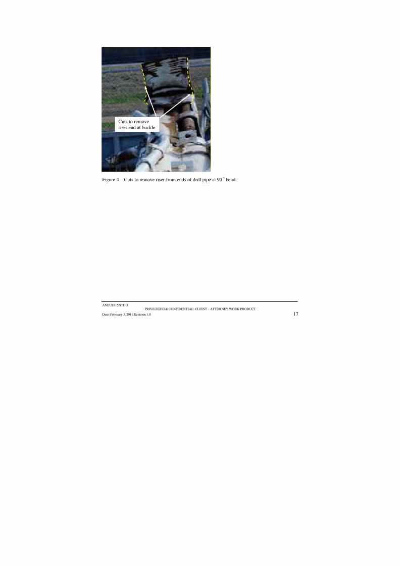
8/7/2019 DNV BOP report - Vol 2 (2)
http://slidepdf.com/reader/full/dnv-bop-report-vol-2-2 73/350

8/7/2019 DNV BOP report - Vol 2 (2)
http://slidepdf.com/reader/full/dnv-bop-report-vol-2-2 74/350
ANEUS815NTHO
PRIVILEGED & CONFIDENTIAL: CLIENT – ATTORNEY WORK PRODUCT
Date: February 3, 2011 Revision 1.0 18
APPENDIX B
REMOVAL OF METALLURGICAL AND MECHANICAL
SAMPLES FROM RECOVERED PIPE SECTIONS

8/7/2019 DNV BOP report - Vol 2 (2)
http://slidepdf.com/reader/full/dnv-bop-report-vol-2-2 75/350

8/7/2019 DNV BOP report - Vol 2 (2)
http://slidepdf.com/reader/full/dnv-bop-report-vol-2-2 76/350
ANEUS815NTHO
PRIVILEGED & CONFIDENTIAL: CLIENT – ATTORNEY WORK PRODUCT
Date: February 3, 2011 Revision 1.0 20
APPENDIX C
REMOVAL OF METALLURGICAL SAMPLE FROM
RECOVERED PIPE SECTION 1-B-1
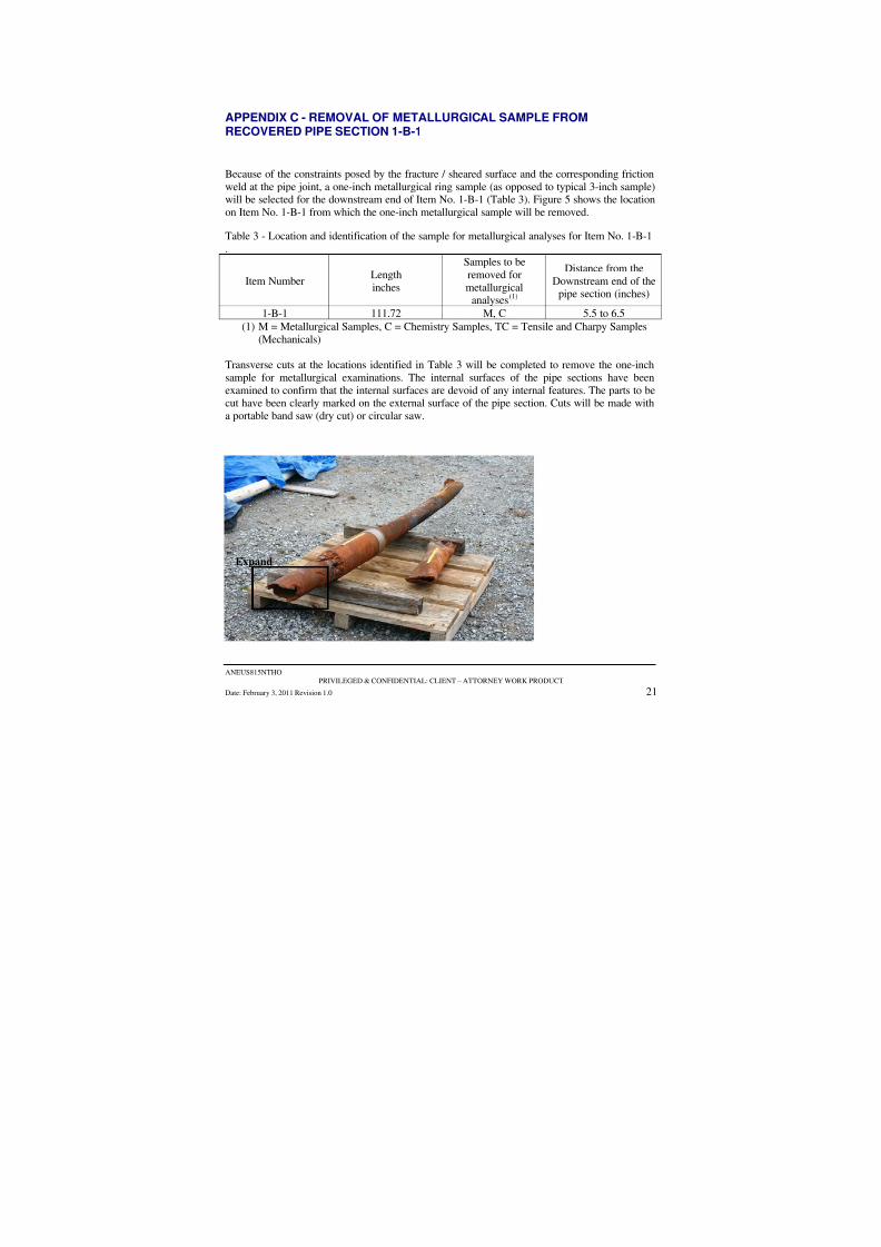
8/7/2019 DNV BOP report - Vol 2 (2)
http://slidepdf.com/reader/full/dnv-bop-report-vol-2-2 77/350
ANEUS815NTHO
PRIVILEGED & CONFIDENTIAL: CLIENT – ATTORNEY WORK PRODUCT
Date: February 3, 2011 Revision 1.0 21
APPENDIX C - REMOVAL OF METALLURGICAL SAMPLE FROMRECOVERED PIPE SECTION 1-B-1
Because of the constraints posed by the fracture / sheared surface and the corresponding friction
weld at the pipe joint, a one-inch metallurgical ring sample (as opposed to typical 3-inch sample)will be selected for the downstream end of Item No. 1-B-1 (Table 3). Figure 5 shows the location
on Item No. 1-B-1 from which the one-inch metallurgical sample will be removed.
Table 3 - Location and identification of the sample for metallurgical analyses for Item No. 1-B-1
.
Item NumberLength
inches
Samples to be
removed for
metallurgicalanalyses(1)
Distance from the
Downstream end of thepipe section (inches)
1-B-1 111.72 M, C 5.5 to 6.5
(1) M = Metallurgical Samples, C = Chemistry Samples, TC = Tensile and Charpy Samples
(Mechanicals)
Transverse cuts at the locations identified in Table 3 will be completed to remove the one-inch
sample for metallurgical examinations. The internal surfaces of the pipe sections have been
examined to confirm that the internal surfaces are devoid of any internal features. The parts to becut have been clearly marked on the external surface of the pipe section. Cuts will be made with
a portable band saw (dry cut) or circular saw.
Expand

8/7/2019 DNV BOP report - Vol 2 (2)
http://slidepdf.com/reader/full/dnv-bop-report-vol-2-2 78/350
ANEUS815NTHO
PRIVILEGED & CONFIDENTIAL: CLIENT – ATTORNEY WORK PRODUCT
Date: February 3, 2011 Revision 1.0 22
Figure 5 – Area to cut Item No. 1-B-1.
8/7/2019 DNV BOP report - Vol 2 (2)
http://slidepdf.com/reader/full/dnv-bop-report-vol-2-2 79/350
ANEUS815NTHO
PRIVILEGED & CONFIDENTIAL: CLIENT – ATTORNEY WORK PRODUCT
Date: February 3, 2011 Revision 1.0 23
APPENDIX D
REMOVAL OF SHEARED DRILL PIPE ENDS FOR SECTIONS
83 AND 94.

8/7/2019 DNV BOP report - Vol 2 (2)
http://slidepdf.com/reader/full/dnv-bop-report-vol-2-2 80/350

8/7/2019 DNV BOP report - Vol 2 (2)
http://slidepdf.com/reader/full/dnv-bop-report-vol-2-2 81/350
8/7/2019 DNV BOP report - Vol 2 (2)
http://slidepdf.com/reader/full/dnv-bop-report-vol-2-2 82/350

8/7/2019 DNV BOP report - Vol 2 (2)
http://slidepdf.com/reader/full/dnv-bop-report-vol-2-2 83/350
DET NORSKE VERITAS
DNV
TEST PROCEDURE METALLURGICAL INVESTIGATION
OF DRILL PIPE
BOP
FORENSIC INVESTIGATION
Rev. 1.0 February 21, 2011 2 of 6 BOP TEST PROCEDURE PRIVILEGED & CONFIDENTIAL – CLIENT ATTORNEY WORK PRODUCT
2. Examine surfaces using a stereo microscope where appropriate.
3. Cut Item 83-Z to reveal the surfaces that are curled into the ID of the pipe (see Figure 1 andError! Not a valid bookmark self-reference.).
4. Examine and photograph the cut surfaces from both sides of the pipe section Item 83-Z.
5. Cut fracture surface area from Item 1-B-1-Z (see Figure 3 and Figure 4).
6. Prepare cut pieces for insertion into the Scanning Electron Microscope (SEM). This appliesto samples cut from both sides of the pipe section Item 83-Z and Item 1-B-1-Z.
a. The height of the sample is critical for fitting into the SEM.
b. A second cut for Item 83-Z will likely be required to maintain a maximum height of approximately 0.5-inches. This cut will be made following examination after the
initial cuts on both sides of the pipe.
c. It is expected that the total length of the cut sample will fit into the SEM, but this
will be evaluated following the previous cuts.
7. Examine the surfaces in the SEM.
a. General features of surfaces.
b. Perform Energy Dispersive Spectroscopy (EDS) on surfaces of interest.

8/7/2019 DNV BOP report - Vol 2 (2)
http://slidepdf.com/reader/full/dnv-bop-report-vol-2-2 84/350
DET NORSKE VERITAS
DNV
TEST PROCEDURE METALLURGICAL INVESTIGATION
OF DRILL PIPE
BOP
FORENSIC INVESTIGATION
Rev. 1.0 February 21, 2011 3 of 6 BOP TEST PROCEDURE PRIVILEGED & CONFIDENTIAL – CLIENT ATTORNEY WORK PRODUCT
Figure 1 – Documentation of the proposed cut on Item 83 on the side without the “flat”
ExistingCrack
Cut
Do not
disturbcorner
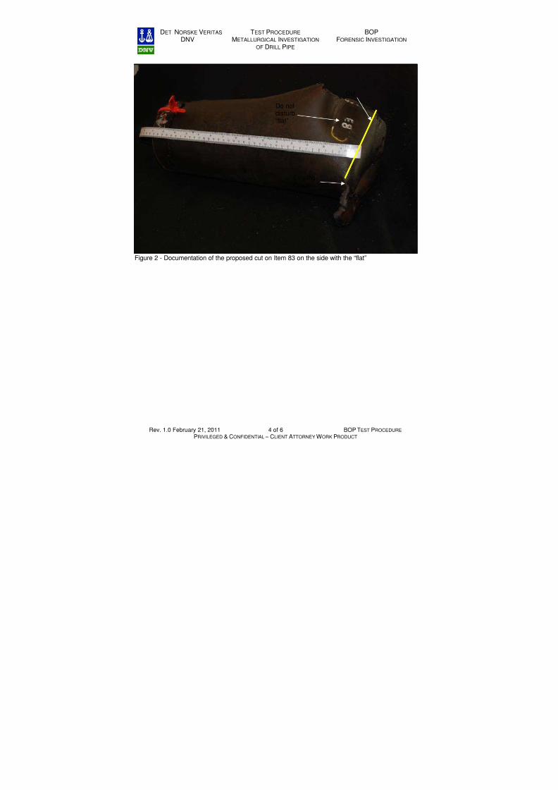
8/7/2019 DNV BOP report - Vol 2 (2)
http://slidepdf.com/reader/full/dnv-bop-report-vol-2-2 85/350
DET NORSKE VERITAS
DNV
TEST PROCEDURE METALLURGICAL INVESTIGATION
OF DRILL PIPE
BOP
FORENSIC INVESTIGATION
Rev. 1.0 February 21, 2011 4 of 6 BOP TEST PROCEDURE PRIVILEGED & CONFIDENTIAL – CLIENT ATTORNEY WORK PRODUCT
Figure 2 - Documentation of the proposed cut on Item 83 on the side with the “flat”
ExistingCrack
Cut
Do notdisturb“flat”
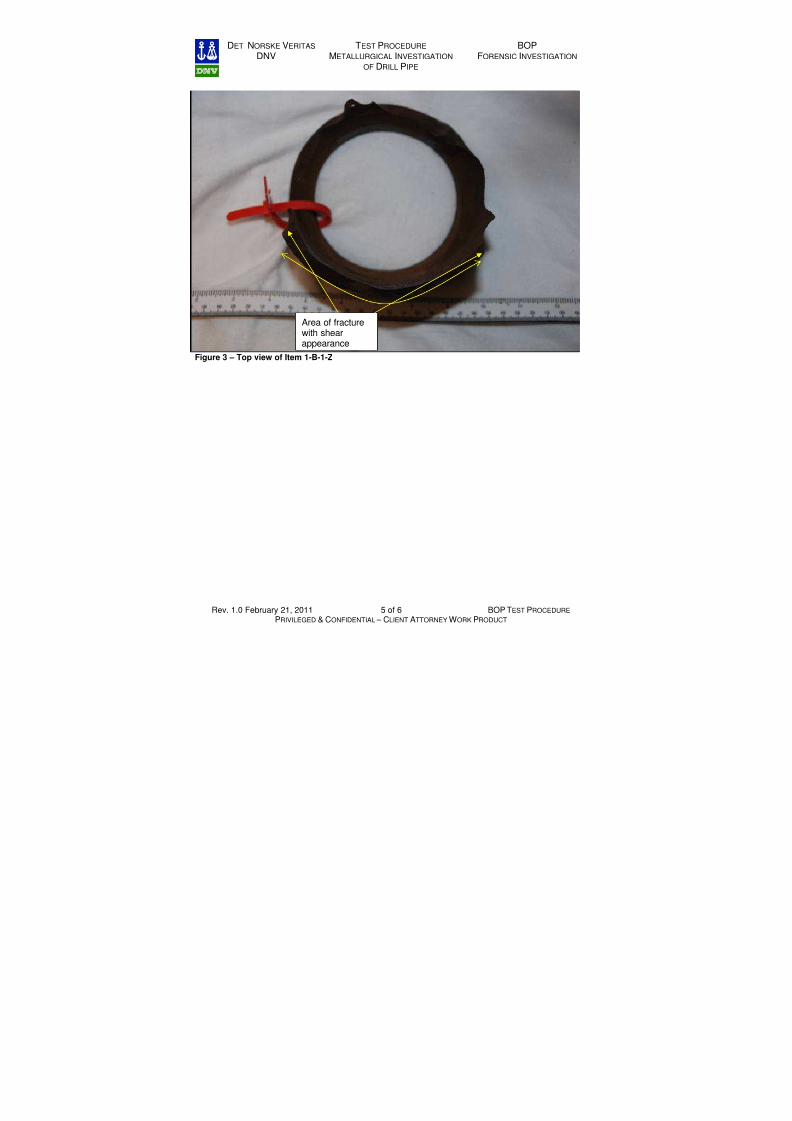
8/7/2019 DNV BOP report - Vol 2 (2)
http://slidepdf.com/reader/full/dnv-bop-report-vol-2-2 86/350
DET NORSKE VERITAS
DNV
TEST PROCEDURE METALLURGICAL INVESTIGATION
OF DRILL PIPE
BOP
FORENSIC INVESTIGATION
Rev. 1.0 February 21, 2011 5 of 6 BOP TEST PROCEDURE PRIVILEGED & CONFIDENTIAL – CLIENT ATTORNEY WORK PRODUCT
Figure 3 – Top view of Item 1-B-1-Z
Area of fracturewith shearappearance

8/7/2019 DNV BOP report - Vol 2 (2)
http://slidepdf.com/reader/full/dnv-bop-report-vol-2-2 87/350
DET NORSKE VERITAS
DNV
TEST PROCEDURE METALLURGICAL INVESTIGATION
OF DRILL PIPE
BOP
FORENSIC INVESTIGATION
Rev. 1.0 February 21, 2011 6 of 6 BOP TEST PROCEDURE PRIVILEGED & CONFIDENTIAL – CLIENT ATTORNEY WORK PRODUCT
Figure 4 – Area to be cut from Item 1-B-1-Z.
Cut to examinefracture surface

8/7/2019 DNV BOP report - Vol 2 (2)
http://slidepdf.com/reader/full/dnv-bop-report-vol-2-2 88/350
DET NORSKE VERITAS United States Department of the Interior, Bureau of Ocean Energy
Management, Regulation, and Enforcement
Forensic Examination of Deepwater Horizon Blowout Preventer
Volume II Appendices
EP030842
20 March 2011
APPENDIX B
SCANNED DRAWINGS
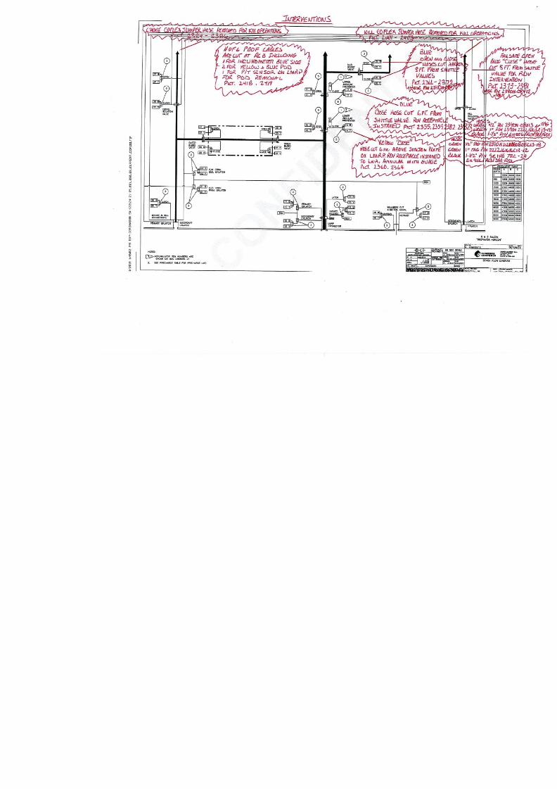
8/7/2019 DNV BOP report - Vol 2 (2)
http://slidepdf.com/reader/full/dnv-bop-report-vol-2-2 89/350

8/7/2019 DNV BOP report - Vol 2 (2)
http://slidepdf.com/reader/full/dnv-bop-report-vol-2-2 90/350

8/7/2019 DNV BOP report - Vol 2 (2)
http://slidepdf.com/reader/full/dnv-bop-report-vol-2-2 91/350

8/7/2019 DNV BOP report - Vol 2 (2)
http://slidepdf.com/reader/full/dnv-bop-report-vol-2-2 92/350
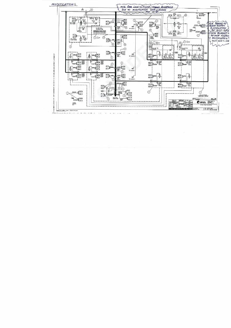
8/7/2019 DNV BOP report - Vol 2 (2)
http://slidepdf.com/reader/full/dnv-bop-report-vol-2-2 93/350
8/7/2019 DNV BOP report - Vol 2 (2)
http://slidepdf.com/reader/full/dnv-bop-report-vol-2-2 94/350

8/7/2019 DNV BOP report - Vol 2 (2)
http://slidepdf.com/reader/full/dnv-bop-report-vol-2-2 95/350
DET NORSKE VERITAS United States Department of the Interior, Bureau of Ocean EnergyManagement, Regulation, and Enforcement
Forensic Examination of Deepwater Horizon Blowout PreventerAppendix C Documents Reviewed
EP030842
20 March 2011
DOCUMENTS REVIEWED
Document
Reference
Number Document Title/ Description
1. BOP Schematics – Flow Diagrams: Shear Ram Kit (TRN-USCG_MMS-00013703)
2. BOP Schematics – Flow Diagrams: Stack Flow Diagram (TRN-USCG_MMS-00013704)
3. BOP Schematics – Flow Diagrams: Stack Flow Diagram (TRN-USCG_MMS-00013705)
4. BOP Schematics – Flow Diagrams: Stack Flow Diagram (TRN-USCG_MMS-00013706)
5. BOP Schematics – Flow Diagrams: Final Assembly (TRN-USCG_MMS-00014355 - 00014358)
6. Cameron Subpoena Files (Jul 6 2010): Engineering Report (CAMCG 00003071 – 00003086)
7. Cameron Subpoena Files (Jul 6 2010): Product Advisory #1005 – Variable Bore Ram Assembly (
00003176)
8. Cameron Subpoena Files (Jul 6 2010): Engineering Errata Sheet: Stripping Recommendations (C
9. Cameron Subpoena Files (Jul 6 2010): Sequence Valve On Site Inspection Procedure (CAMCG 0
10. Cameron Subpoena Files (Jul 6 2010): Field Service Order (CAMCG 00003356 – 00003390)
11. Cameron Subpoena Files: Deep Water Horizon TL BOP Stack Operation and Maintenance Manu00000235)
12. Cameron Subpoena Files: Multiplex BOP Control System Vol. I (CAMCG 00000236 – 00000645
13. Cameron Subpoena Files: Multiplex BOP Control System Vol. II (CAMCG 00000646 – 0000091
14. Cameron Subpoena Files: Multiplex BOP Control System Vol. III (CAMCG 00000920 – 000011
15. Cameron Subpoena Files: Multiplex BOP Control System Vol. IV (CAMCG 00001124 – 000014
16. Cameron Subpoena Files: Multiplex BOP Control System Vol. V (CAMCG 00001428 – 0000162
17. Cameron Subpoena Files: Multiplex BOP Control System Vol. VI (CAMCG 00001621 – 000017
18. Cameron Subpoena Files: Multiplex BOP Control System Vol. VII (CAMCG 00001762 – 00002
19. Cameron Subpoena Files: Multiplex BOP Control System Vol. VIII (CAMCG 00002175 – 00002
20. Cameron Subpoena Files: R&B Falcon Drilling Co. PO: BOP Stack Test System (CAMCG 00002
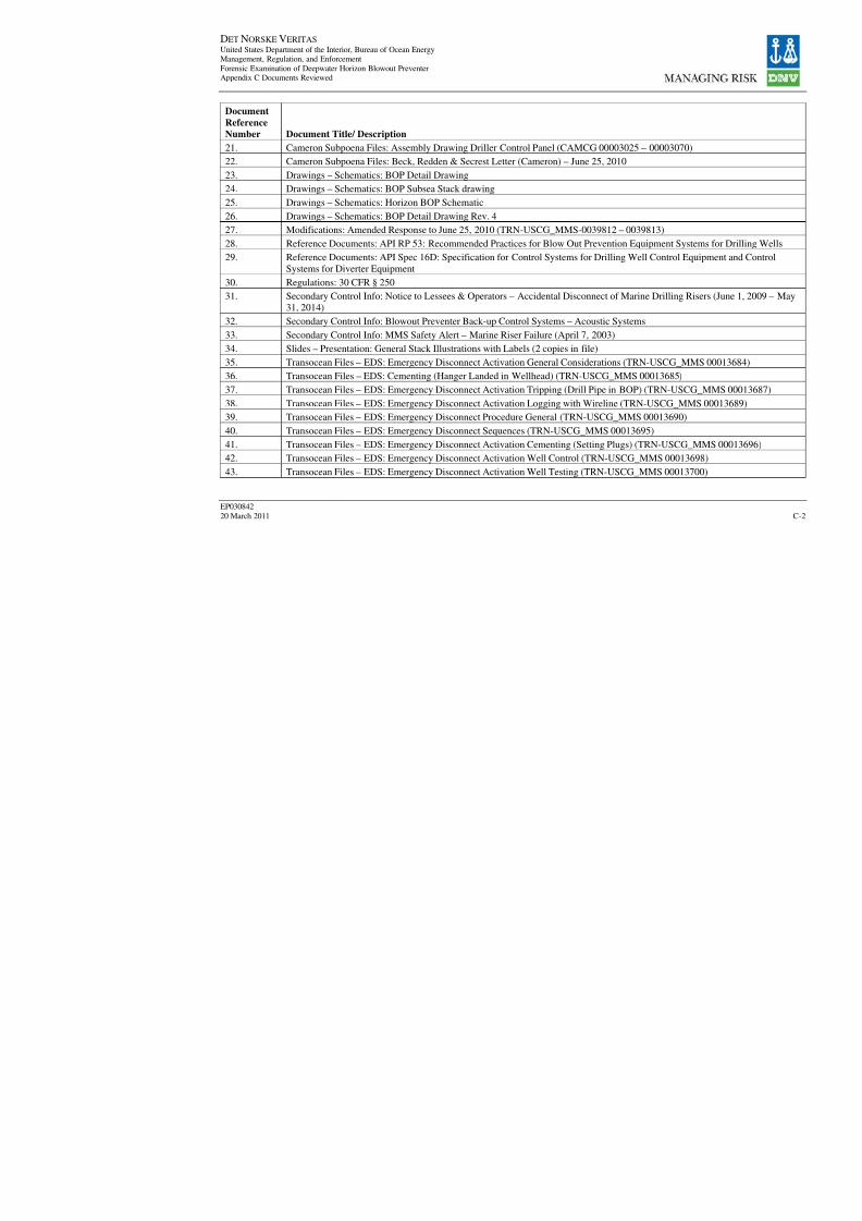
8/7/2019 DNV BOP report - Vol 2 (2)
http://slidepdf.com/reader/full/dnv-bop-report-vol-2-2 96/350
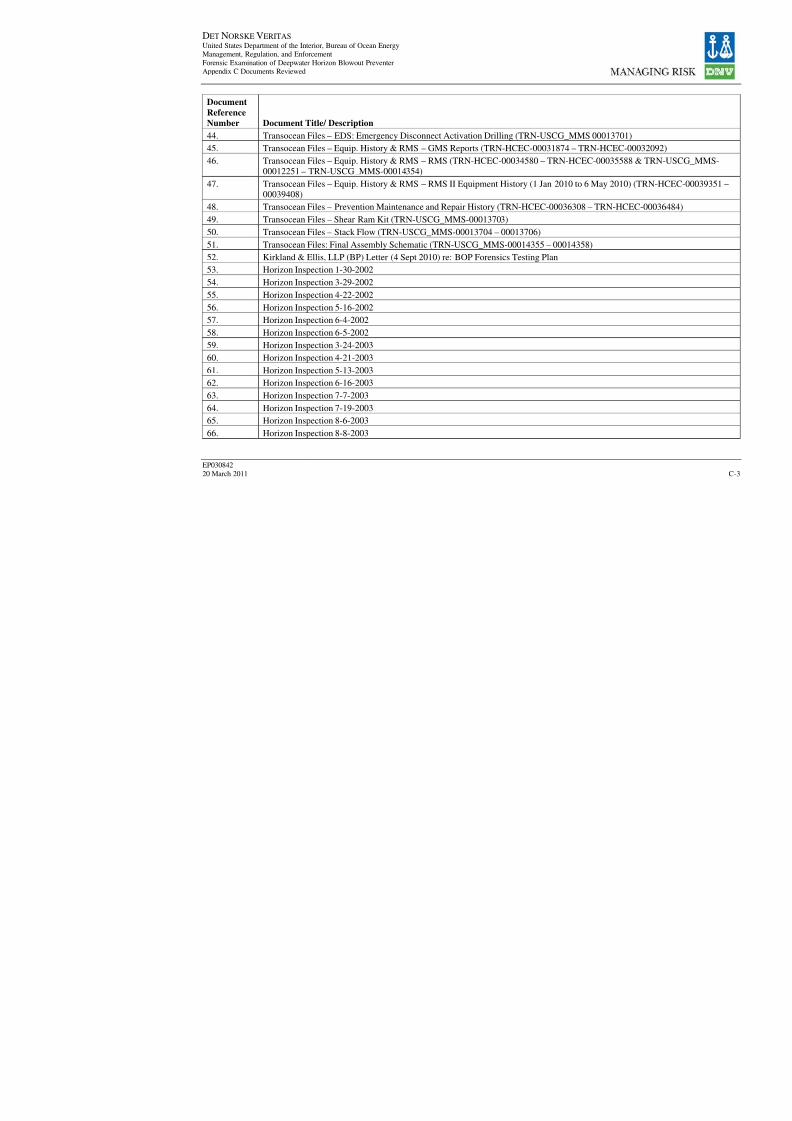
8/7/2019 DNV BOP report - Vol 2 (2)
http://slidepdf.com/reader/full/dnv-bop-report-vol-2-2 97/350
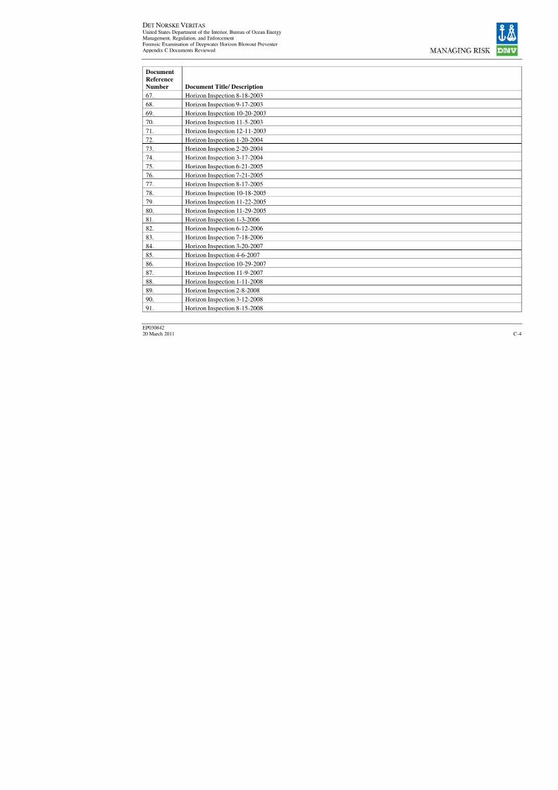
8/7/2019 DNV BOP report - Vol 2 (2)
http://slidepdf.com/reader/full/dnv-bop-report-vol-2-2 98/350
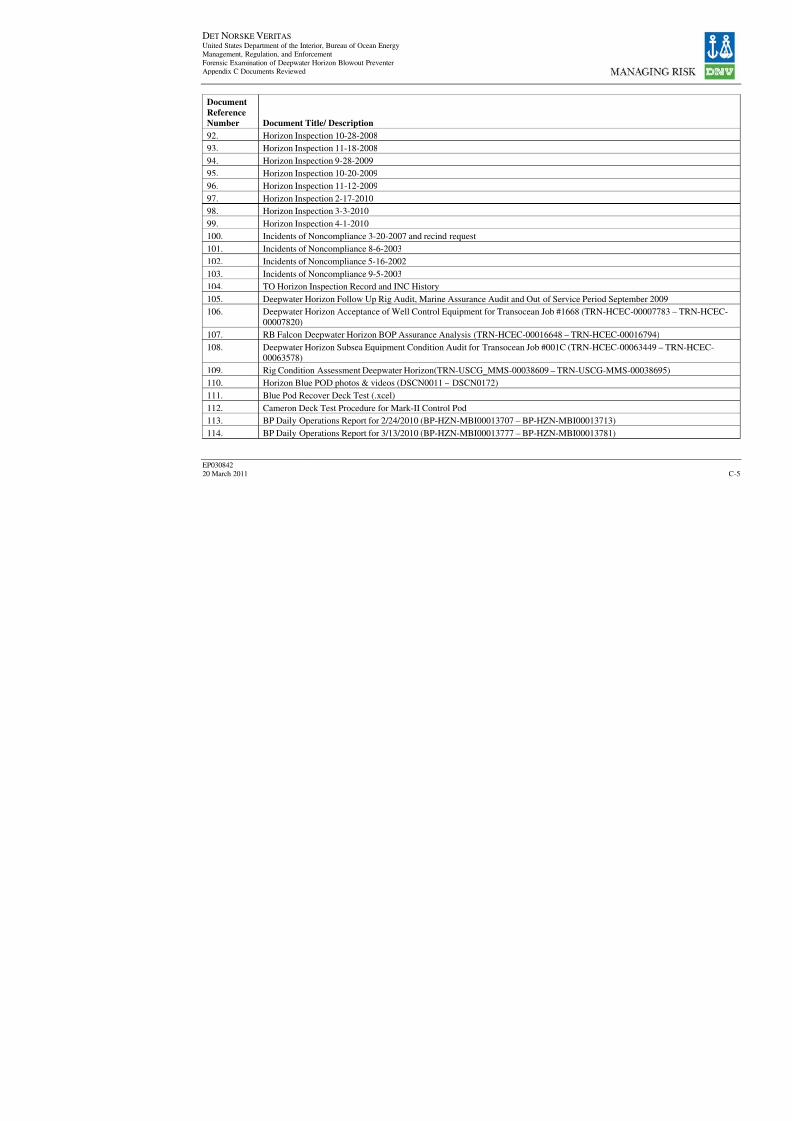
8/7/2019 DNV BOP report - Vol 2 (2)
http://slidepdf.com/reader/full/dnv-bop-report-vol-2-2 99/350
DET NORSKE VERITAS United States Department of the Interior, Bureau of Ocean EnergyManagement, Regulation, and Enforcement
Forensic Examination of Deepwater Horizon Blowout PreventerAppendix C Documents Reviewed
EP030842
20 March 2011
Document
Reference
Number Document Title/ Description92. Horizon Inspection 10-28-2008
93. Horizon Inspection 11-18-2008
94. Horizon Inspection 9-28-2009
95. Horizon Inspection 10-20-2009
96. Horizon Inspection 11-12-2009
97. Horizon Inspection 2-17-2010
98. Horizon Inspection 3-3-2010
99. Horizon Inspection 4-1-2010
100. Incidents of Noncompliance 3-20-2007 and recind request
101.
Incidents of Noncompliance 8-6-2003102. Incidents of Noncompliance 5-16-2002
103. Incidents of Noncompliance 9-5-2003
104. TO Horizon Inspection Record and INC History
105. Deepwater Horizon Follow Up Rig Audit, Marine Assurance Audit and Out of Service Period Sep
106. Deepwater Horizon Acceptance of Well Control Equipment for Transocean Job #1668 (TRN-HC
00007820)
107. RB Falcon Deepwater Horizon BOP Assurance Analysis (TRN-HCEC-00016648 – TRN-HCEC-
108. Deepwater Horizon Subsea Equipment Condition Audit for Transocean Job #001C (TRN-HCEC-
00063578)
109. Rig Condition Assessment Deepwater Horizon(TRN-USCG_MMS-00038609 – TRN-USCG-MM
110. Horizon Blue POD photos & videos (DSCN0011 – DSCN0172)
111. Blue Pod Recover Deck Test (.xcel)
112. Cameron Deck Test Procedure for Mark-II Control Pod
113. BP Daily Operations Report for 2/24/2010 (BP-HZN-MBI00013707 – BP-HZN-MBI00013713)
114. BP Daily Operations Report for 3/13/2010 (BP-HZN-MBI00013777 – BP-HZN-MBI00013781)

8/7/2019 DNV BOP report - Vol 2 (2)
http://slidepdf.com/reader/full/dnv-bop-report-vol-2-2 100/350

8/7/2019 DNV BOP report - Vol 2 (2)
http://slidepdf.com/reader/full/dnv-bop-report-vol-2-2 101/350
DET NORSKE VERITAS United States Department of the Interior, Bureau of Ocean EnergyManagement, Regulation, and Enforcement
Forensic Examination of Deepwater Horizon Blowout PreventerAppendix C Documents Reviewed
EP030842
20 March 2011
Document
Reference
Number Document Title/ Description137. Stack Flow Diagram (BP-HZN-MIB00010427)
138. Cameron TL, BOP Stack Control Equipment, Stack Mounted, 18-3/4”, 15,000 psi WP Schematic
139. Cameron Schematic (BP-HZN-MBI00010438)
140. Foundation of Hot Line Hose Reel (1/2) Schematic (BP-HZN-MBI00017194)
141. Foundation of BOP Storage W/Test Stump (1/3) (BP-HZN-MBI00017216 – BP-HZN-MBI00017
142. Foundation of BOP Storage W/Test Stump (2/3) (BP-HZN-MBI00017218 – BP-HZN-MBI00017
143. Foundation of BOP Storage W/Test Stump (3/3) (BP-HZN-MBI00017220 – BP-HZN-MBI00017
144. Foundation of Remote Control Stand for Blue Reel and Yellow Reel (BP-HZN-MBI00017230 – B
145. Arrangement of BOP Control Room (BP-HZN-MBI00017274 – BP-HZN-MBI00017275)
146.
Foundation of BOP Control Main HPU (BP-HZN-MBI00017278 – BP-HZN-MBI00017279)147. Foundation of BOP Accumulator Rack (BP-HZN-MBI00017284 – BP-HZN-MBI00017285)
148. Foundation of BOP Bottle Rack (BP-HZN-MBI00017286 – BP-HZN-MBI00017287)
149. Detail of Padeye For Maintenance (1/4) BOP Control Unit Room (BP-HZN-MBI00017346 – BP-
150. Machinery Arrangement on MUX Reel Platform (BP-HZN-MBI00017354 – BP-HZN-MBI00017
151. Foundation of LMRP Storage W/Test Stump (1/2) (BP-HZN-MBI00017458 – BP-HZN-MBI000
152. Foundation of LMRP Storage W/Test Stump (2/2) (BP-HZN-MBI00017460 – BP-HZN-MBI000
153. Foundation of Hot Line & MUX Hose Turndown Sheaves (2/3) (BP-HZN-MBI00017622 – BP-H
154. Foundation of LMRP Bulkhead Guide (2/4) (BP-HZN-MBI00017688 – BP-HZN-MBI00017689)
155. Cameron TL, BOP Stack Control Equipment, Stack Mounted, 18-3/4” 15,000 psi WP (BP-HZN-M
MBI00018248)
156. Cameron TL, BOP Stack Control Equipment, Stack Mounted, 18-3/4” 15,000 psi WP (BP-HZN-M
MBI00018263)
157. Evaluation of Secondary Intervention Methods in Well Control (by West Eng. For MMS: March
– BP-HZN-MBI00010554)
158. Subsea Pressure Test-Feb. 9-10, 2010 (BP-HZN-MBI00002458 – BP-HZN-MBI00002463)

8/7/2019 DNV BOP report - Vol 2 (2)
http://slidepdf.com/reader/full/dnv-bop-report-vol-2-2 102/350
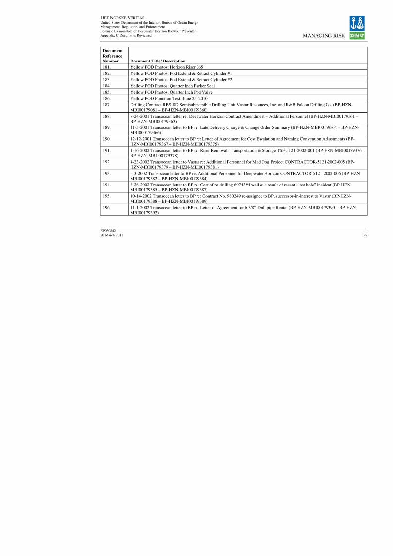
8/7/2019 DNV BOP report - Vol 2 (2)
http://slidepdf.com/reader/full/dnv-bop-report-vol-2-2 103/350
DET NORSKE VERITAS United States Department of the Interior, Bureau of Ocean EnergyManagement, Regulation, and Enforcement
Forensic Examination of Deepwater Horizon Blowout PreventerAppendix C Documents Reviewed
EP030842
20 March 2011
Document
Reference
Number Document Title/ Description181. Yellow POD Photos: Horizon Riser 065
182. Yellow POD Photos: Pod Extend & Retract Cylinder #1
183. Yellow POD Photos: Pod Extend & Retract Cylinder #2
184. Yellow POD Photos: Quarter inch Packer Seal
185. Yellow POD Photos: Quarter Inch Pod Valve
186. Yellow POD Function Test: June 25, 2010
187. Drilling Contract RBS-8D Semisubmersible Drilling Unit Vastar Resources, Inc. and R&B Falcon
MBI00179081 – BP-HZN-MBI00179360)
188. 7-24-2001 Transocean letter re: Deepwater Horizon Contract Amendment – Additional Personnel
BP-HZN-MBI00179363)
189. 11-5-2001 Transocean letter to BP re: Late Delivery Charge & Change Order Summary (BP-HZN
MBI000179366)
190. 12-12-2001 Transocean letter to BP re: Letter of Agreement for Cost Escalation and Naming Con
HZN-MBI00179367 – BP-HZN-MBI00179375)
191. 1-16-2002 Transocean letter to BP re: Riser Removal, Transportation & Storage TSF-5121-2002-
BP-HZN-MBI-00179378)
192. 4-23-2002 Transocean letter to Vastar re: Additional Personnel for Mad Dog Project CONTRACTHZN-MBI00179379 – BP-HZN-MBI00179381)
193. 6-3-2002 Transocean letter to BP re: Additional Personnel for Deepwater Horizon CONTRACTO
MBI00179382 – BP-HZN-MBI00179384)
194. 8-26-2002 Transocean letter to BP re: Cost of re-drilling 60743#4 well as a result of recent “lost h
MBI00179385 – BP-HZN-MBI00179387)
195. 10-14-2002 Transocean letter to BP re: Contract No. 980249 re-assigned to BP, successor-in-inter
MBI00179388 – BP-HZN-MBI00179389)
196. 11-1-2002 Transocean letter to BP re: Letter of Agreement for 6 5/8” Drill pipe Rental (BP-HZN-
MBI00179392)
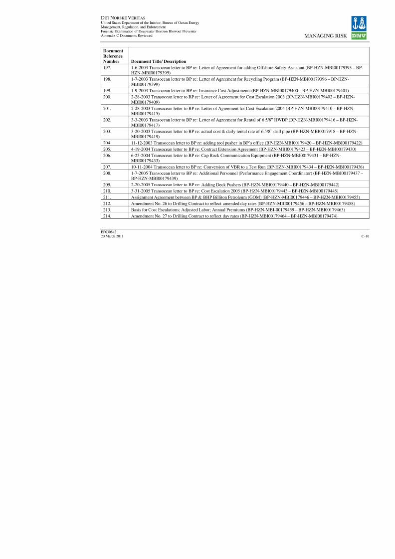
8/7/2019 DNV BOP report - Vol 2 (2)
http://slidepdf.com/reader/full/dnv-bop-report-vol-2-2 104/350
DET NORSKE VERITAS United States Department of the Interior, Bureau of Ocean EnergyManagement, Regulation, and Enforcement
Forensic Examination of Deepwater Horizon Blowout PreventerAppendix C Documents Reviewed
EP030842
20 March 2011
Document
Reference
Number Document Title/ Description197. 1-6-2003 Transocean letter to BP re: Letter of Agreement for adding Offshore Safety Assistant (B
HZN-MBI00179395)
198. 1-7-2003 Transocean letter to BP re: Letter of Agreement for Recycling Program (BP-HZN-MBI0
MBI00179399)
199. 1-9-2003 Transocean letter to BP re: Insurance Cost Adjustments (BP-HZN-MBI00179400 – BP-
200. 2-28-2003 Transocean letter to BP re: Letter of Agreement for Cost Escalation 2003 (BP-HZN-M
MBI00179409)
201. 2-28-2003 Transocean letter to BP re: Letter of Agreement for Cost Escalation 2004 (BP-HZN-M
MBI00179415)
202. 3-3-2003 Transocean letter to BP re: Letter of Agreement for Rental of 6 5/8” HWDP (BP-HZN-M
MBI00179417)203. 3-20-2003 Transocean letter to BP re: actual cost & daily rental rate of 6 5/8” drill pipe (BP-HZN
MBI00179419)
204. 11-12-2003 Transocean letter to BP re: adding tool pusher in BP’s office (BP-HZN-MBI0017942
205. 4-19-2004 Transocean letter to BP re: Contract Extension Agreement (BP-HZN-MBI00179423 –
206. 6-25-2004 Transocean letter to BP re: Cap Rock Communication Equipment (BP-HZN-MBI0017MBI00179433)
207. 10-11-2004 Transocean letter to BP re: Conversion of VBR to a Test Run (BP-HZN-MBI001794
208. 1-7-2005 Transocean letter to BP re: Additional Personnel (Performance Engagement Coordinato
BP-HZN-MBI00179439)
209. 2-20-2005 Transocean letter to BP re: Adding Deck Pushers (BP-HZN-MBI00179440 – BP-HZN
210. 3-31-2005 Transocean letter to BP re: Cost Escalation 2005 (BP-HZN-MBI00179443 – BP-HZN
211. Assignment Agreement between BP & BHP Billiton Petroleum (GOM) (BP-HZN-MBI00179446
212. Amendment No. 26 to Drilling Contract to reflect amended day rates (BP-HZN-MBI00179456 –
213. Basis for Cost Escalations; Adjusted Labor; Annual Premiums (BP-HZN-MBI-00179459 – BP-H
214. Amendment No. 27 to Drilling Contract to reflect day rates (BP-HZN-MBI00179464 – BP-HZN-
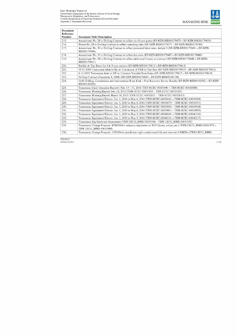
8/7/2019 DNV BOP report - Vol 2 (2)
http://slidepdf.com/reader/full/dnv-bop-report-vol-2-2 105/350
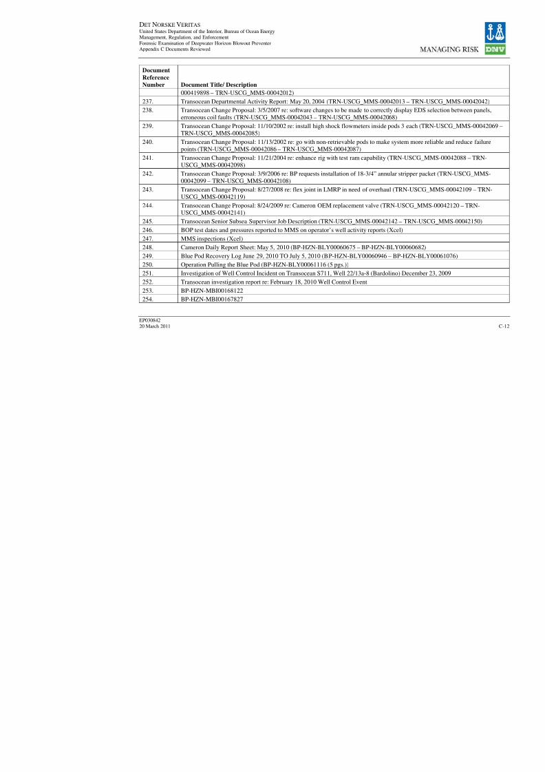
8/7/2019 DNV BOP report - Vol 2 (2)
http://slidepdf.com/reader/full/dnv-bop-report-vol-2-2 106/350
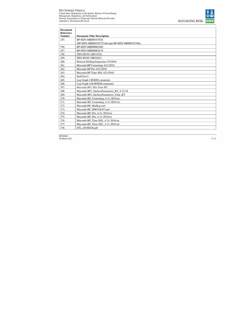
8/7/2019 DNV BOP report - Vol 2 (2)
http://slidepdf.com/reader/full/dnv-bop-report-vol-2-2 107/350

8/7/2019 DNV BOP report - Vol 2 (2)
http://slidepdf.com/reader/full/dnv-bop-report-vol-2-2 108/350
DET NORSKE VERITAS United States Department of the Interior, Bureau of Ocean EnergyManagement, Regulation, and Enforcement
Forensic Examination of Deepwater Horizon Blowout PreventerAppendix C Documents Reviewed
EP030842
20 March 2011
Document
Reference
Number Document Title/ Description279. Surface_time_log_cementing.pdf
280. BP-HZN-MBI00208965.pdf
281. BP-HZN-MBI00208965.xls
282. BP-HZN-MBI00208966.pdf
283. BP-HZN-MBI00208972.pdf
284. BP-HZN-MBI00208973.pdf
285. BP-HZN-MBI00208975.pdf
286. BP-HZN-MBI00208976.pdf
287. BP-HZN-MBI00208978.pdf
288.
BP-HZN-MBI00208980.pdf 289. BP-HZN-MBI00208982.pdf
290. BP-HZN-MBI00208983.pdf
291. BP-HZN-MBI00208985.pdf
292. BP-HZN-MBI00208987.pdf
293. BP-HZN-MBI00208988.pdf
294. BP-HZN-MBI00208990.pdf
295. BP-HZN-MBI00208991.pdf
296. BP-HZN-MBI00208992.pdf
297. BP-HZN-MBI00208994.pdf
298.
BP-HZN-MBI00208995.pdf 299. BP-HZN-MBI00208997.pdf
300. BP-HZN-MBI00208999.pdf
301. BP-HZN-MBI00209000.pdf
302. BP-HZN-MBI00209002.pdf
303. BP-HZN-MBI00209003.pdf

8/7/2019 DNV BOP report - Vol 2 (2)
http://slidepdf.com/reader/full/dnv-bop-report-vol-2-2 109/350
DET NORSKE VERITAS United States Department of the Interior, Bureau of Ocean EnergyManagement, Regulation, and Enforcement
Forensic Examination of Deepwater Horizon Blowout PreventerAppendix C Documents Reviewed
EP030842
20 March 2011
Document
Reference
Number Document Title/ Description304. BP-HZN-MBI00209005.pdf
305. BP-HZN-MBI00209007.pdf
306. BP-HZN-MBI00209009.pdf
307. BP-HZN-MBI00209010.pdf
308. BP-HZN-MBI00209012.pdf
309. BP-HZN-MBI00209013.pdf
310. BP-HZN-MBI00209015.pdf
311. BP-HZN-MBI00209017.pdf
312. BP-HZN-MBI00209019.pdf
313.
BP-HZN-MBI00209021.pdf 314. BP-HZN-MBI00209023.pdf
315. BP-HZN-MBI00209024.pdf
316. BP-HZN-MBI00209025.pdf
317. BP-HZN-MBI00209027.pdf
318. BP-HZN-MBI00209030.pdf
319. BP-HZN-MBI00209032.pdf
320. BP-HZN-MBI00209034.pdf
321. BP-HZN-MBI00209035.pdf
322. BP-HZN-MBI00209037.pdf
323.
BP-HZN-MBI00209039.pdf 324. BP-HZN-MBI00209041.pdf
325. BP-HZN-MBI00209043.pdf
326. BP-HZN-MBI00209044.pdf
327. BP-HZN-MBI00209045.pdf
328. BP-HZN-MBI00209047.pdf
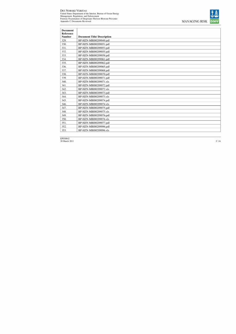
8/7/2019 DNV BOP report - Vol 2 (2)
http://slidepdf.com/reader/full/dnv-bop-report-vol-2-2 110/350
DET NORSKE VERITAS United States Department of the Interior, Bureau of Ocean EnergyManagement, Regulation, and Enforcement
Forensic Examination of Deepwater Horizon Blowout PreventerAppendix C Documents Reviewed
EP030842
20 March 2011
Document
Reference
Number Document Title/ Description329. BP-HZN-MBI00209049.pdf
330. BP-HZN-MBI00209051.pdf
331. BP-HZN-MBI00209053.pdf
332. BP-HZN-MBI00209055.pdf
333. BP-HZN-MBI00209058.pdf
334. BP-HZN-MBI00209061.pdf
335. BP-HZN-MBI00209062.pdf
336. BP-HZN-MBI00209065.pdf
337. BP-HZN-MBI00209068.pdf
338.
BP-HZN-MBI00209070.pdf 339. BP-HZN-MBI00209071.pdf
340. BP-HZN-MBI00209071.xls
341. BP-HZN-MBI00209072.pdf
342. BP-HZN-MBI00209072.xls
343. BP-HZN-MBI00209073.pdf
344. BP-HZN-MBI00209073.xls
345. BP-HZN-MBI00209074.pdf
346. BP-HZN-MBI00209074.xls
347. BP-HZN-MBI00209075.pdf
348.
BP-HZN-MBI00209075.xls349. BP-HZN-MBI00209076.pdf
350. BP-HZN-MBI00209076.xls
351. BP-HZN-MBI00209077.pdf
352. BP-HZN-MBI00209096.pdf
353. BP-HZN-MBI00209096.xls
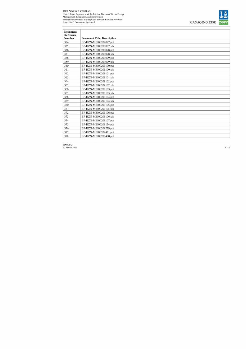
8/7/2019 DNV BOP report - Vol 2 (2)
http://slidepdf.com/reader/full/dnv-bop-report-vol-2-2 111/350
DET NORSKE VERITAS United States Department of the Interior, Bureau of Ocean EnergyManagement, Regulation, and Enforcement
Forensic Examination of Deepwater Horizon Blowout PreventerAppendix C Documents Reviewed
EP030842
20 March 2011
Document
Reference
Number Document Title/ Description354. BP-HZN-MBI00209097.pdf
355. BP-HZN-MBI00209097.xls
356. BP-HZN-MBI00209098.pdf
357. BP-HZN-MBI00209098.xls
358. BP-HZN-MBI00209099.pdf
359. BP-HZN-MBI00209099.xls
360. BP-HZN-MBI00209100.pdf
361. BP-HZN-MBI00209100.xls
362. BP-HZN-MBI00209101.pdf
363.
BP-HZN-MBI00209101.xls364. BP-HZN-MBI00209102.pdf
365. BP-HZN-MBI00209102.xls
366. BP-HZN-MBI00209103.pdf
367. BP-HZN-MBI00209103.xls
368. BP-HZN-MBI00209104.pdf
369. BP-HZN-MBI00209104.xls
370. BP-HZN-MBI00209105.pdf
371. BP-HZN-MBI00209105.xls
372. BP-HZN-MBI00209106.pdf
373.
BP-HZN-MBI00209106.xls374. BP-HZN-MBI00209107.pdf
375. BP-HZN-MBI00209134.pdf
376. BP-HZN-MBI00209279.pdf
377. BP-HZN-MBI00209421.pdf
378. BP-HZN-MBI00209490.pdf

8/7/2019 DNV BOP report - Vol 2 (2)
http://slidepdf.com/reader/full/dnv-bop-report-vol-2-2 112/350
DET NORSKE VERITAS United States Department of the Interior, Bureau of Ocean EnergyManagement, Regulation, and Enforcement
Forensic Examination of Deepwater Horizon Blowout PreventerAppendix C Documents Reviewed
EP030842
20 March 2011
Document
Reference
Number Document Title/ Description379. BP-HZN-MBI00209553.pdf
380. BP-HZN-MBI00209648.pdf
381. BP-HZN-MBI00209694.pdf
382. BP-HZN-MBI00209765.pdf
383. BP-HZN-MBI00209830.pdf
384. BP-HZN-MBI00209900.pdf
385. BP-HZN-MBI00210040.pdf
386. BP-HZN-MBI00210132.pdf
387. BP-HZN-MBI00210178.pdf
388.
BP-HZN-MBI00210305.pdf 389. BP-HZN-MBI00210429.pdf
390. BP-HZN-MBI00210553.pdf
391. BP-HZN-MBI00210643.pdf
392. BP-HZN-MBI00210733.pdf
393. BP-HZN-MBI00210822.pdf
394. BP-HZN-MBI00210915.pdf
395. BP-HZN-MBI00211098.pdf
396. BP-HZN-MBI00211128.pdf
397. BP-HZN-MBI00211143.pdf
398.
BP-HZN-MBI00211160.pdf 399. BP-HZN-MBI00211224.pdf
400. BP-HZN-MBI00211242.pdf
401. BP-HZN-MBI00211242.xls
402. BP-HZN-MBI00211243.pdf
403. BP-HZN-MBI00211243.xls
8/7/2019 DNV BOP report - Vol 2 (2)
http://slidepdf.com/reader/full/dnv-bop-report-vol-2-2 113/350

8/7/2019 DNV BOP report - Vol 2 (2)
http://slidepdf.com/reader/full/dnv-bop-report-vol-2-2 114/350
8/7/2019 DNV BOP report - Vol 2 (2)
http://slidepdf.com/reader/full/dnv-bop-report-vol-2-2 115/350
8/7/2019 DNV BOP report - Vol 2 (2)
http://slidepdf.com/reader/full/dnv-bop-report-vol-2-2 116/350

8/7/2019 DNV BOP report - Vol 2 (2)
http://slidepdf.com/reader/full/dnv-bop-report-vol-2-2 117/350
8/7/2019 DNV BOP report - Vol 2 (2)
http://slidepdf.com/reader/full/dnv-bop-report-vol-2-2 118/350

8/7/2019 DNV BOP report - Vol 2 (2)
http://slidepdf.com/reader/full/dnv-bop-report-vol-2-2 119/350
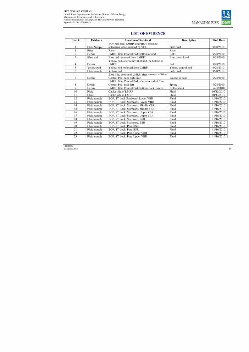
8/7/2019 DNV BOP report - Vol 2 (2)
http://slidepdf.com/reader/full/dnv-bop-report-vol-2-2 120/350
DET NORSKE VERITAS United States Department of the Interior, Bureau of Ocean EnergyManagement, Regulation, and Enforcement
Forensic Examination of Deepwater Horizon Blowout PreventerAppendix D List of Evidence
EP030842
20 March 2011
LIST OF EVIDENCE
Item # Evidence Location of Retrieval Descriptio
1 Fluid Sample
BOP pod side, LMRP, after ROV pressure
activation valve initiated by VFL Pink fluid
1 Riser Riser Riser
2 Debris LMRP, Blue Control Pod, bottom of unit Bolt
3 Blue pod Blue pod removed from LMRP Blue control pod
4 Debris
Yellow pod, after removal of unit, on bottom of
LMRP Bolt
5 Yellow pod Yellow pod removed from LMRP Yellow control pod
6 Fluid sample Yellow pod Pink fluid
7 Debris
Blue side, bottom of LMRP, after removal of Blue
Control Pod, back right side Washer or seal
8 Debris
LMRP, Blue Control Pod, after removal of Blue
Control Pod, back left Spring
9 Debris LMRP, Blue Control Pod, bottom, back, center Bolt and nut
10 Fluid Choke side of LMRP Fluid
11 Fluid Choke side of LMRP Fluid
12 Fluid sample BOP, ST Lock Starboard, Lower VBR Fluid
13 Fluid sample BOP, ST Lock, Starboard, Lower VBR Fluid
14 Fluid sample BOP, ST Lock, Starboard, Middle VBR Fluid
15 Fluid sample BOP, ST Lock, Starboard, Middle VBR Fluid
16 Fluid sample BOP, ST Lock, Starboard, Upper VBR Fluid
17 Fluid sample BOP, ST Lock, Starboard, Upper VBR Fluid
18 Fluid sample BOP, ST Lock, Starboard, BSR Fluid 19 Fluid sample BOP, ST Lock, Starboard, BSR Fluid
20 Fluid sample BOP, ST Lock, Port, BSR Fluid
21 Fluid sample BOP, ST Lock, Port, BSR Fluid
22 Fluid sample BOP, ST Lock, Port, Upper VBR Fluid
23 Fluid sample BOP, ST Lock, Port, Upper VBR Fluid
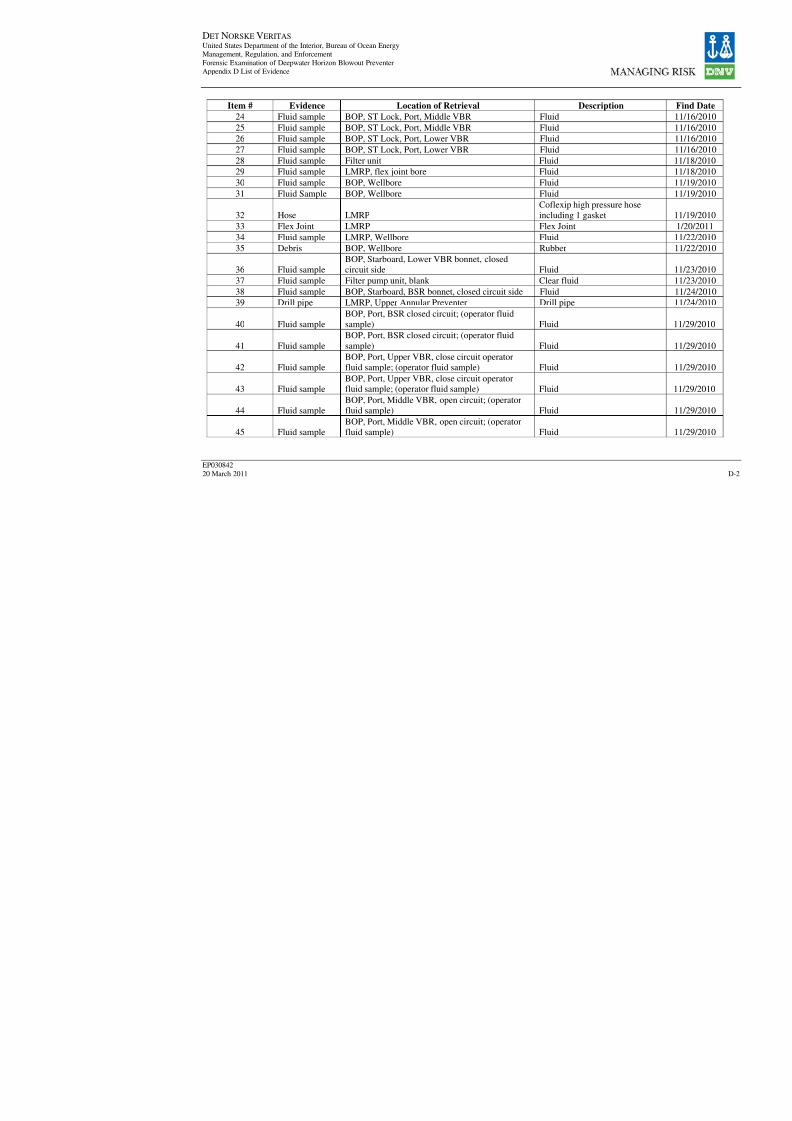
8/7/2019 DNV BOP report - Vol 2 (2)
http://slidepdf.com/reader/full/dnv-bop-report-vol-2-2 121/350

8/7/2019 DNV BOP report - Vol 2 (2)
http://slidepdf.com/reader/full/dnv-bop-report-vol-2-2 122/350
DET NORSKE VERITAS United States Department of the Interior, Bureau of Ocean EnergyManagement, Regulation, and Enforcement
Forensic Examination of Deepwater Horizon Blowout PreventerAppendix D List of Evidence
EP030842
20 March 2011
Item # Evidence Location of Retrieval Descriptio
46 Fluid sample BOP, bonnet drill pump Clear fluid
47 Fluid sampleBOP, Port, Lower VBR, closed circuit; (operatorfluid sample) Fluid
48 Fluid sample
BOP, Port, Lower VBR, closed circuit; (operator
fluid sample) Fluid
49 Fluid sample
BOP, stud side Upper VBR closed circuit;
(operator fluid sample) Fluid
50 Fluid sample
BOP, stud side Upper VBR open circuit; (operatorfluid sample) Fluid
51 Fluid sample
BOP, stud side, Middle VBR, closed circuit,
(operator fluid sample) Fluid
52 Fluid sample
BOP, stud side, Middle VBR, open circuit,
operator sample tube Fluid
53 Fluid sample
Bonnet drill pump blank sample from filter pump
unit Clear fluid
54 Fluid sample
BOP, Starboard, open circuit, Middle VBR(operator fluid sample) Pink Fluid
55 Fluid sample
BOP, Starboard, open circuit, Lower VBR
(operator fluid sample) Pink Fluid
56 Fluid sample
Bonnet drill pump blank sample from filter pump
unit Clear fluid
57 Port BSR BSR - Port Ram
58
Sample of
debris BSR - Port Mud
59 Debris BSR - Port Scrapings and mud
60 Debris BSR - Port
Scrapings and debris f
side of Port BSR
61 Debris BSR - Port
Scrapings and debris f
side of Port BSR
62 Debris BSR - Port
Scrapings and debris f
side of Port BSR

8/7/2019 DNV BOP report - Vol 2 (2)
http://slidepdf.com/reader/full/dnv-bop-report-vol-2-2 123/350
DET NORSKE VERITAS United States Department of the Interior, Bureau of Ocean EnergyManagement, Regulation, and Enforcement
Forensic Examination of Deepwater Horizon Blowout PreventerAppendix D List of Evidence
EP030842
20 March 2011
Item # Evidence Location of Retrieval Descriptio
63 Debris BSR - Port
Debris from underside
Starboard BSR
64 Debris BSR - Port
Cubic debris attached
side of Port BSR
65 Fluid sample
Hoses connected to lower, inner, and outer close
valve open side/Yellow Control Pod Pink fluid
66 Fluid sample
Hoses connected to lower, inner, and outer open
valve open side/Yellow Control Pod Pink fluid
67 Fluid sample
Upper BSR from ROV panel out of shear ram
close Port Pink fluid
68 Starboard BSR BSR - Starboard Ram
68 Debris BSR - Starboard Mud
68 Debris BSR - Starboard 2 pieces of hard plasti
69 Debris BSR - Starboard; from Item 68 Mud
70 Debris BSR - Starboard; from Item 68 Mud
71 Fluid sample
BOP lower, inner, and outer choke, Blue Control
Pod, close side Pink fluid
72 Fluid sample
BOP lower, inner, and outer choke, Blue ControlPod, open side Pink fluid
73 Debris BOP/Starboard BSR bonnet face & ram cavity Mud
74 Fluid sample BOP wellbore through choke line Pink fluid
75 Debris BOP/Port, BSR bonnet face and ram cavity Mud
76 Debris BSR - Starboard; 18 bags from Item 68
Rubber, metallic piece
shot"
77 Fluid samplePort hose (blue) from Yellow Control Pod to openshutter valve on CSR Pink fluid
78 Fluid sample
Port from Blue Control Pod hose connected to
open shutter valve on CSR Pink fluid
79 Fluid sample
Port from Blue Control Pod hose connected to
CSR closed shutter valve Pink fluid
80 Debris CSR - Port, ram cavity & bonnet face Mud
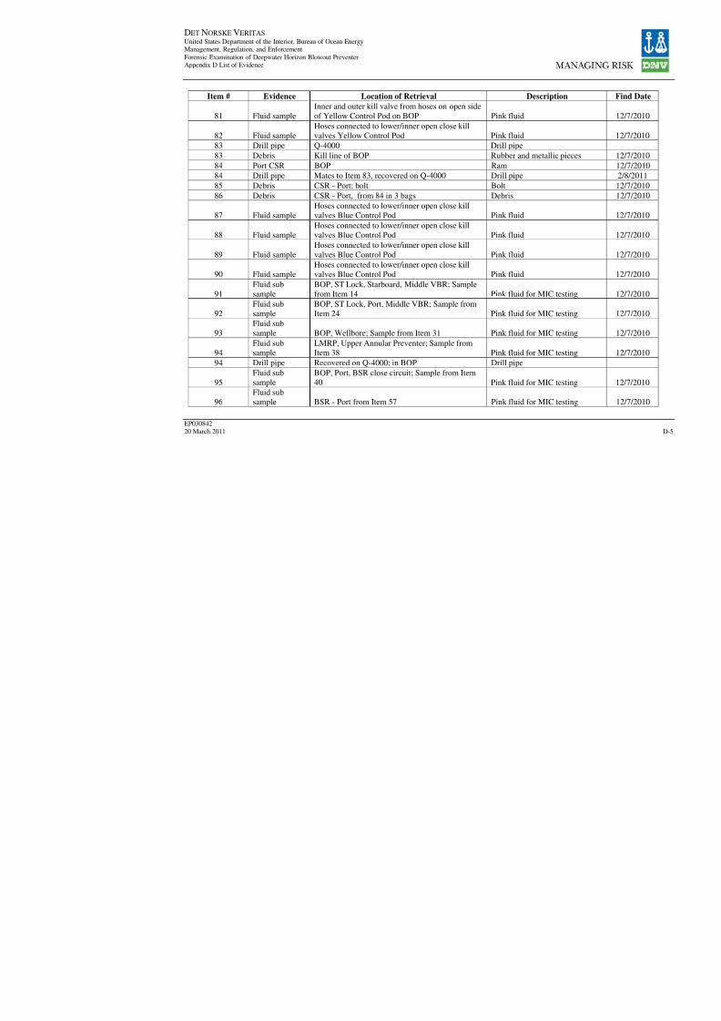
8/7/2019 DNV BOP report - Vol 2 (2)
http://slidepdf.com/reader/full/dnv-bop-report-vol-2-2 124/350

8/7/2019 DNV BOP report - Vol 2 (2)
http://slidepdf.com/reader/full/dnv-bop-report-vol-2-2 125/350
DET NORSKE VERITAS United States Department of the Interior, Bureau of Ocean EnergyManagement, Regulation, and Enforcement
Forensic Examination of Deepwater Horizon Blowout PreventerAppendix D List of Evidence
EP030842
20 March 2011
Item # Evidence Location of Retrieval Descriptio
97 Fluid sample Starboard CSR open operator Pink fluid
98 Fluid sample Starboard, CSR open operator Pink fluid 99 Fluid sample Upper Middle and Lower Port ST Lock hoses Pink fluid
100
CSR pin
Starboard/debri
s CSR - Starboard Starboard CSR pin an
101
Debris/fluid
sample CSR - Starboard bonnet & ram Pink fluid and mud
102 Debris CSR - Starboard connecting rod and seal Mud and cloth materi
103
Starboard CSR
pin CSR - Starboard Pin for Starboard CSR
104 Starboard CSR BOP Ram
105
Debris/fluid
sample CSR - Starboard cavity Mud and pink fluid
106 Fluid sample Starboard ST Lock hoses Pink fluid
107
Connecting rod
seal Starboard CSR connecting rod seal Sample #1 Seal
108
Connecting rod
seal Starboard CSR connecting rod seal Sample #2 Seal
109
Connecting rod
seal Starboard CSR connecting rod seal Sample #3 Seal
110
Connecting rod
seal Starboard CSR connecting rod seal Sample #4 Seal
111
Port Upper
VBR BOP Ram
112
Starboard
Upper VBR BOP Ram
113 Fluid sample Starboard Upper VBR ST Lock-close Brown-pink fluid
114 Fluid sample Port Upper VBR ST Lock-close side Pink fluid, bolt
115 Debris Upper VBR - Port bonnet and ram cavity Mud
116 Debris Top of Upper VBRs Mud
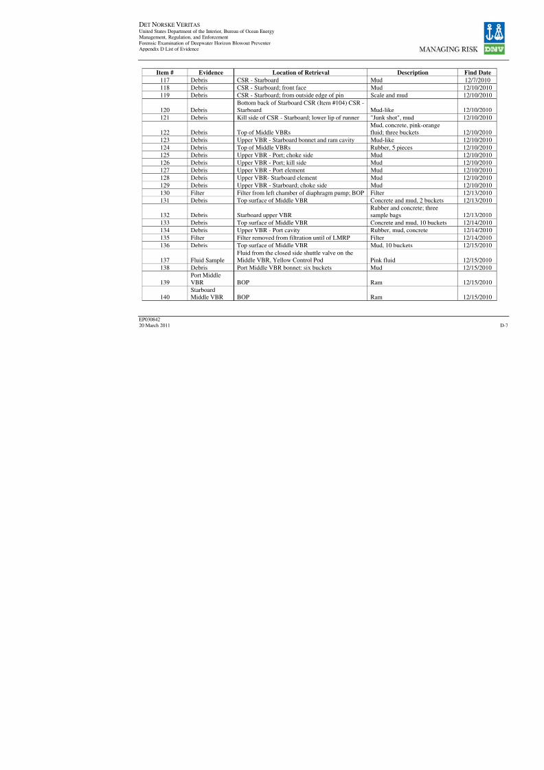
8/7/2019 DNV BOP report - Vol 2 (2)
http://slidepdf.com/reader/full/dnv-bop-report-vol-2-2 126/350
DET NORSKE VERITAS United States Department of the Interior, Bureau of Ocean EnergyManagement, Regulation, and Enforcement
Forensic Examination of Deepwater Horizon Blowout PreventerAppendix D List of Evidence
EP030842
20 March 2011
Item # Evidence Location of Retrieval Descriptio
117 Debris CSR - Starboard Mud
118 Debris CSR - Starboard; front face Mud 119 Debris CSR - Starboard; from outside edge of pin Scale and mud
120 Debris
Bottom back of Starboard CSR (Item #104) CSR -
Starboard Mud-like
121 Debris Kill side of CSR - Starboard; lower lip of runner "Junk shot", mud
122 Debris Top of Middle VBRs
Mud, concrete, pink-o
fluid; three buckets
123 Debris Upper VBR - Starboard bonnet and ram cavity Mud-like
124 Debris Top of Middle VBRs Rubber, 5 pieces
125 Debris Upper VBR - Port; choke side Mud
126 Debris Upper VBR - Port; kill side Mud
127 Debris Upper VBR - Port element Mud 128 Debris Upper VBR- Starboard element Mud
129 Debris Upper VBR - Starboard; choke side Mud
130 Filter Filter from left chamber of diaphragm pump; BOP Filter
131 Debris Top surface of Middle VBR Concrete and mud, 2 b
132 Debris Starboard upper VBR
Rubber and concrete;
sample bags
133 Debris Top surface of Middle VBR Concrete and mud, 10
134 Debris Upper VBR - Port cavity Rubber, mud, concret
135 Filter Filter removed from filtration until of LMRP Filter
136 Debris Top surface of Middle VBR Mud, 10 buckets
137 Fluid Sample
Fluid from the closed side shuttle valve on the
Middle VBR, Yellow Control Pod Pink fluid 138 Debris Port Middle VBR bonnet: six buckets Mud
139
Port Middle
VBR BOP Ram
140
Starboard
Middle VBR BOP Ram
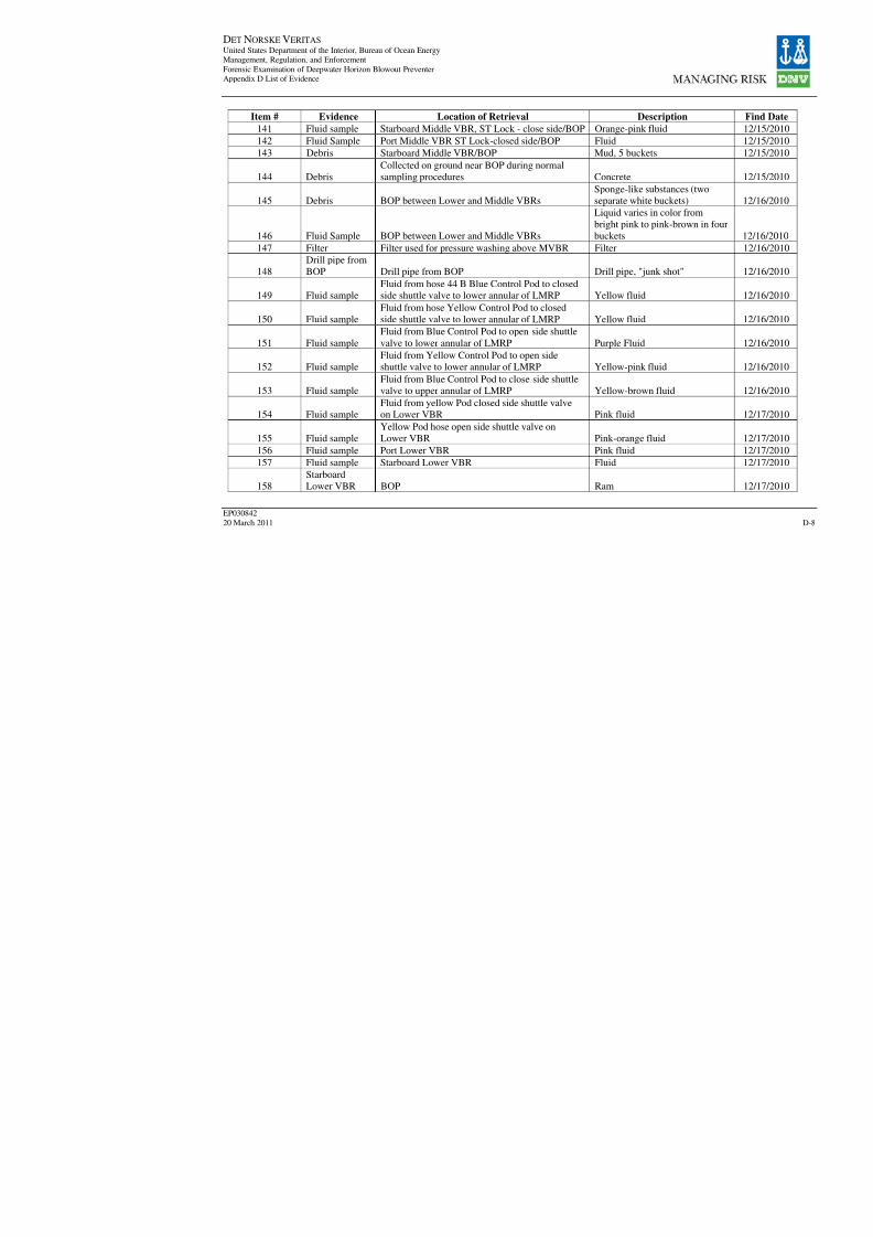
8/7/2019 DNV BOP report - Vol 2 (2)
http://slidepdf.com/reader/full/dnv-bop-report-vol-2-2 127/350
DET NORSKE VERITAS United States Department of the Interior, Bureau of Ocean EnergyManagement, Regulation, and Enforcement
Forensic Examination of Deepwater Horizon Blowout PreventerAppendix D List of Evidence
EP030842
20 March 2011
Item # Evidence Location of Retrieval Descriptio
141 Fluid sample Starboard Middle VBR, ST Lock - close side/BOP Orange-pink fluid
142 Fluid Sample Port Middle VBR ST Lock-closed side/BOP Fluid 143 Debris Starboard Middle VBR/BOP Mud, 5 buckets
144 Debris
Collected on ground near BOP during normal
sampling procedures Concrete
145 Debris BOP between Lower and Middle VBRs
Sponge-like substance
separate white bucket
146 Fluid Sample BOP between Lower and Middle VBRs
Liquid varies in color
bright pink to pink-br
buckets
147 Filter Filter used for pressure washing above MVBR Filter
148
Drill pipe from
BOP Drill pipe from BOP Drill pipe, "junk shot"
149 Fluid sample
Fluid from hose 44 B Blue Control Pod to closed
side shuttle valve to lower annular of LMRP Yellow fluid
150 Fluid sample
Fluid from hose Yellow Control Pod to closed
side shuttle valve to lower annular of LMRP Yellow fluid
151 Fluid sample
Fluid from Blue Control Pod to open side shuttle
valve to lower annular of LMRP Purple Fluid
152 Fluid sample
Fluid from Yellow Control Pod to open side
shuttle valve to lower annular of LMRP Yellow-pink fluid
153 Fluid sample
Fluid from Blue Control Pod to close side shuttle
valve to upper annular of LMRP Yellow-brown fluid
154 Fluid sample
Fluid from yellow Pod closed side shuttle valve
on Lower VBR Pink fluid
155 Fluid sample
Yellow Pod hose open side shuttle valve on
Lower VBR Pink-orange fluid
156 Fluid sample Port Lower VBR Pink fluid
157 Fluid sample Starboard Lower VBR Fluid
158
Starboard
Lower VBR BOP Ram

8/7/2019 DNV BOP report - Vol 2 (2)
http://slidepdf.com/reader/full/dnv-bop-report-vol-2-2 128/350

8/7/2019 DNV BOP report - Vol 2 (2)
http://slidepdf.com/reader/full/dnv-bop-report-vol-2-2 129/350
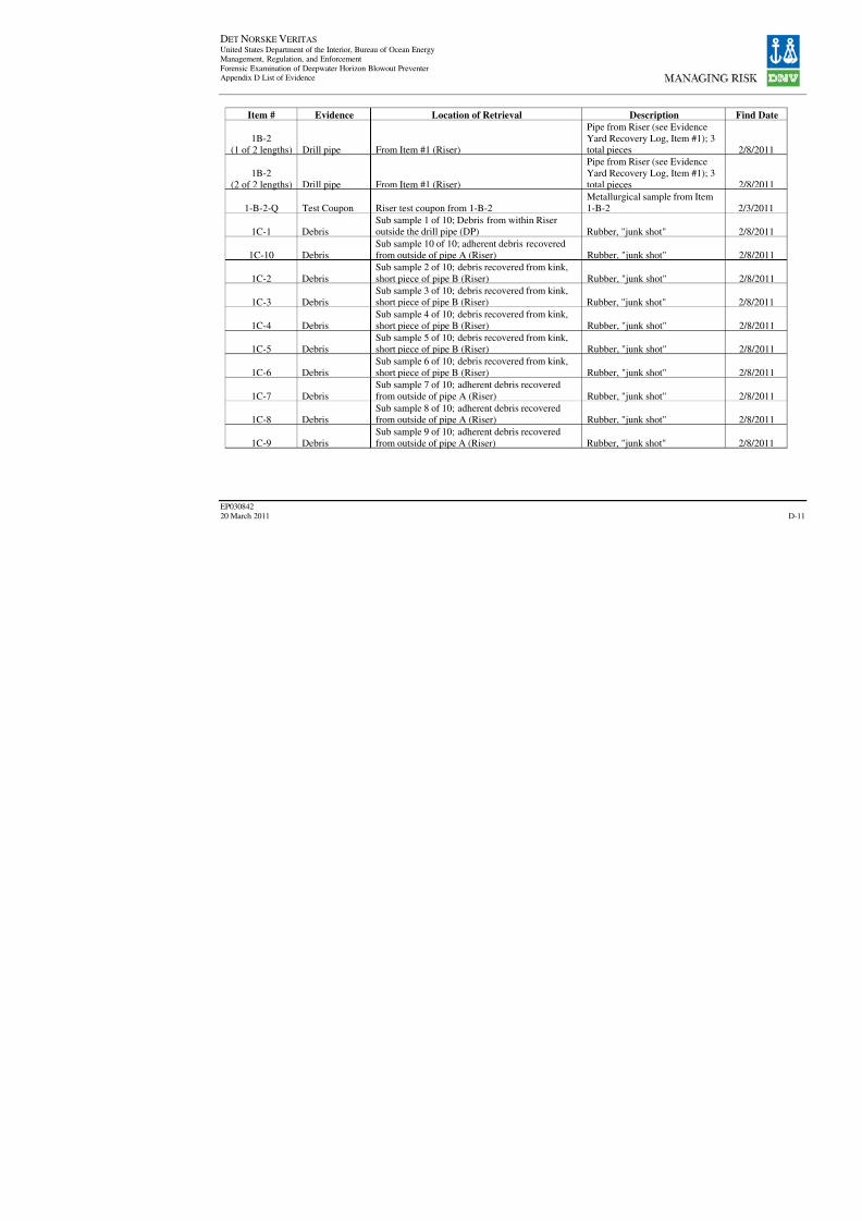
8/7/2019 DNV BOP report - Vol 2 (2)
http://slidepdf.com/reader/full/dnv-bop-report-vol-2-2 130/350

8/7/2019 DNV BOP report - Vol 2 (2)
http://slidepdf.com/reader/full/dnv-bop-report-vol-2-2 131/350
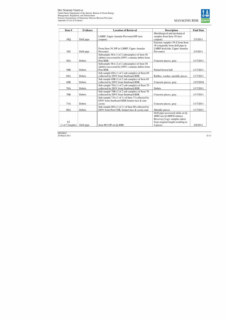
8/7/2019 DNV BOP report - Vol 2 (2)
http://slidepdf.com/reader/full/dnv-bop-report-vol-2-2 132/350
DET NORSKE VERITAS United States Department of the Interior, Bureau of Ocean EnergyManagement, Regulation, and Enforcement
Forensic Examination of Deepwater Horizon Blowout PreventerAppendix D List of Evidence
EP030842
20 March 2011
Item # Evidence Location of Retrieval Descriptio
39Q Drill pipeLMRP, Upper Annular Preventer/DP (testcoupon)
Metallurgical and mec
samples from Item 39coupon)
39Z Drill pipe
From Item 39, DP in LMRP, Upper Annular
Preventer
Fracture samples 39-Z
39 (originally from dr
LMRP dockside, Upp
Preventer)
58A Debris
Subsample 58A (1 of 2 subsamples) of Item 58
(debris) recovered by DNV; contains debris from
Port BSR Concrete pieces, gray
58B Debris
Subsample 58A (2 of 2 subsamples) of Item 58
(debris) recovered by DNV; contains debris from
Port BSR Partial brown ball
69A DebrisSub sample 69A (1 of 2 sub samples) of Item 69collected by DNV from Starboard BSR Rubber, washer, meta
69B Debris
Sub sample 69B (2 of 2 sub samples) of Item 69
collected by DNV from Starboard BSR Concrete pieces, gray
70A Debris
Sub sample 70A (1 of 2 sub samples) of Item 70
collected by DNV from Starboard BSR Debris
70B Debris
Sub sample 70B (2 of 2 sub samples) of Item 70
collected by DNV from Starboard BSR Concrete pieces, gray
73A Debris
Sub sample 73A (1 of 1) of Item 73 collected by
DNV from Starboard BSR bonnet face & ram
cavity Concrete pieces, gray
80A Debris
Sub sample 80A (1 of 1) of Item 80 collected by
DNV from Port CSR, bonnet face & cavity ram Metallic pieces
83
(1 of 2 lengths) Drill pipe Item #83 DP on Q-4000
Drill pipe recovered w
4000 (see Q-4000 Evi
Recovery Log); samp
from original length r
4 pieces
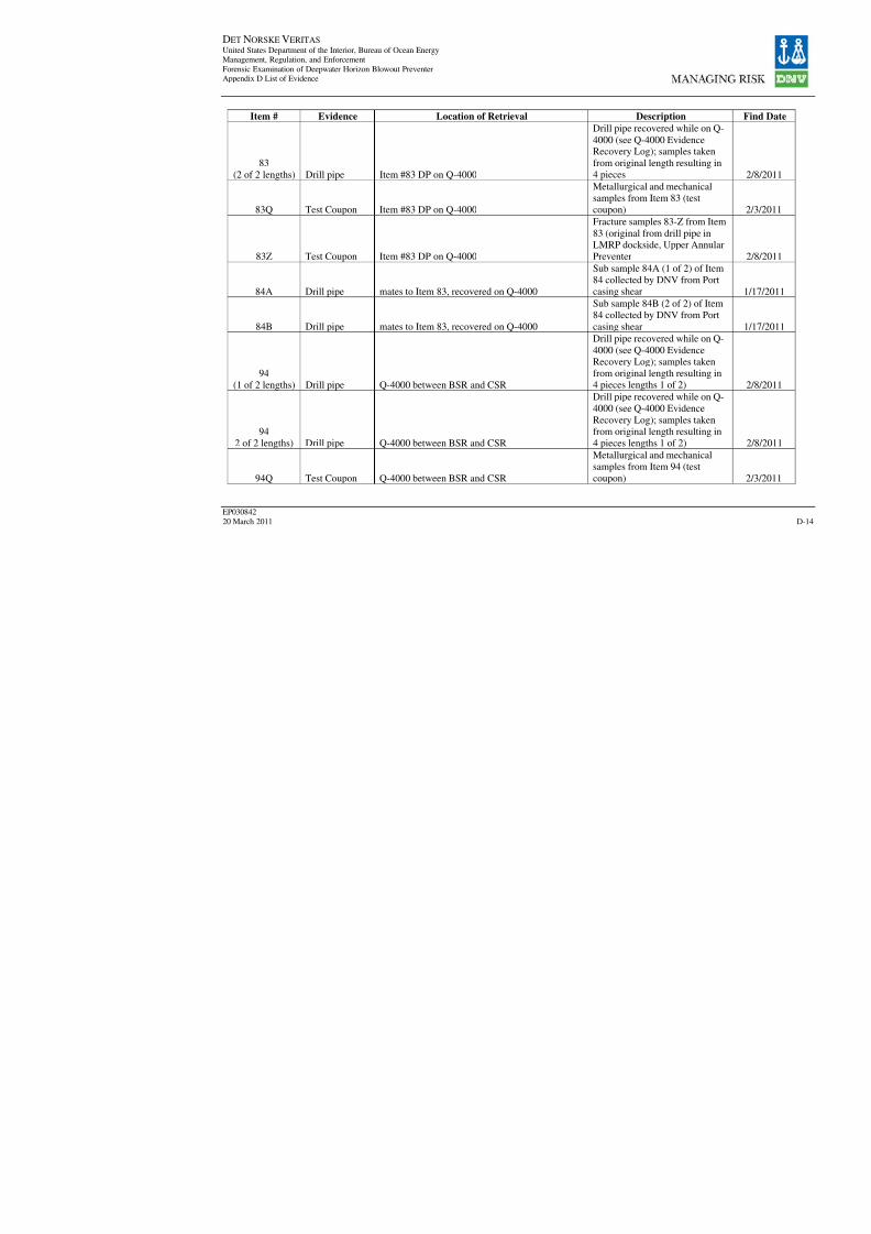
8/7/2019 DNV BOP report - Vol 2 (2)
http://slidepdf.com/reader/full/dnv-bop-report-vol-2-2 133/350
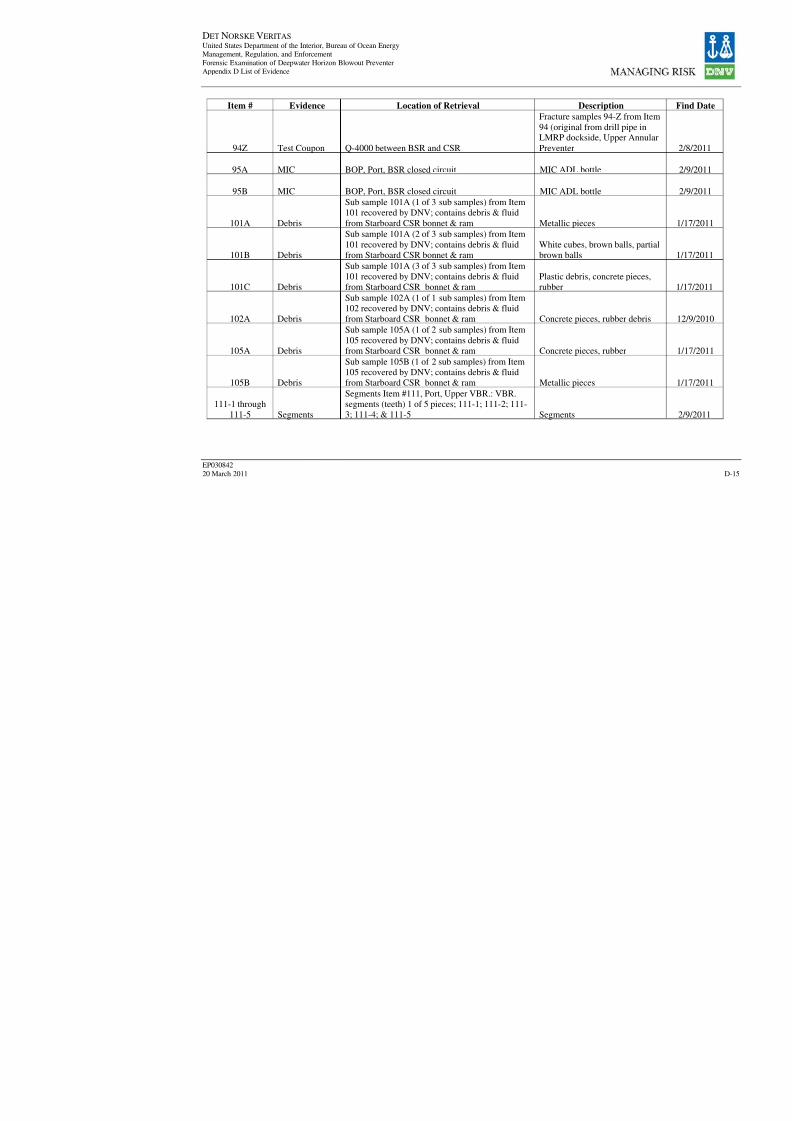
8/7/2019 DNV BOP report - Vol 2 (2)
http://slidepdf.com/reader/full/dnv-bop-report-vol-2-2 134/350
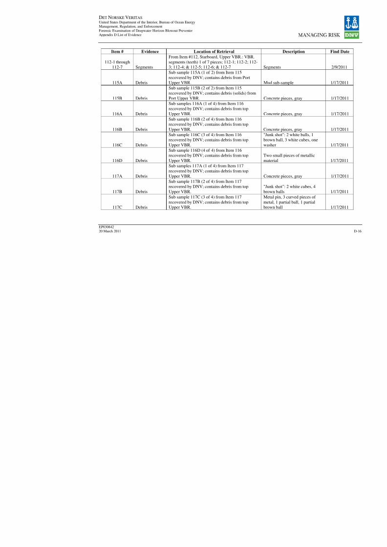
8/7/2019 DNV BOP report - Vol 2 (2)
http://slidepdf.com/reader/full/dnv-bop-report-vol-2-2 135/350
DET NORSKE VERITAS United States Department of the Interior, Bureau of Ocean EnergyManagement, Regulation, and Enforcement
Forensic Examination of Deepwater Horizon Blowout PreventerAppendix D List of Evidence
EP030842
20 March 2011
Item # Evidence Location of Retrieval Descriptio
112-1 through112-7 Segments
From Item #112, Starboard, Upper VBR.: VBR.
segments (teeth) 1 of 7 pieces; 112-1; 112-2; 112-3; 112-4; & 112-5; 112-6; & 112-7 Segments
115A Debris
Sub sample 115A (1 of 2) from Item 115
recovered by DNV; contains debris from Port
Upper VBR. Mud sub-sample
115B Debris
Sub sample 115B (2 of 2) from Item 115
recovered by DNV; contains debris (solids) from
Port Upper VBR. Concrete pieces, gray
116A Debris
Sub samples 116A (1 of 4) from Item 116
recovered by DNV; contains debris from top
Upper VBR. Concrete pieces, gray
116B Debris
Sub sample 116B (2 of 4) from Item 116
recovered by DNV; contains debris from topUpper VBR. Concrete pieces, gray
116C Debris
Sub sample 116C (3 of 4) from Item 116
recovered by DNV; contains debris from top
Upper VBR.
"Junk shot": 2 white b
brown ball, 3 white cu
washer
116D Debris
Sub sample 116D (4 of 4) from Item 116
recovered by DNV; contains debris from top
Upper VBR.
Two small pieces of m
material
117A Debris
Sub samples 117A (1 of 4) from Item 117
recovered by DNV; contains debris from top
Upper VBR. Concrete pieces, gray
117B Debris
Sub sample 117B (2 of 4) from Item 117
recovered by DNV; contains debris from top
Upper VBR.
"Junk shot": 2 white c
brown balls
117C Debris
Sub sample 117C (3 of 4) from Item 117
recovered by DNV; contains debris from topUpper VBR.
Metal pin, 3 curved pi
metal, 1 partial ball, 1brown ball
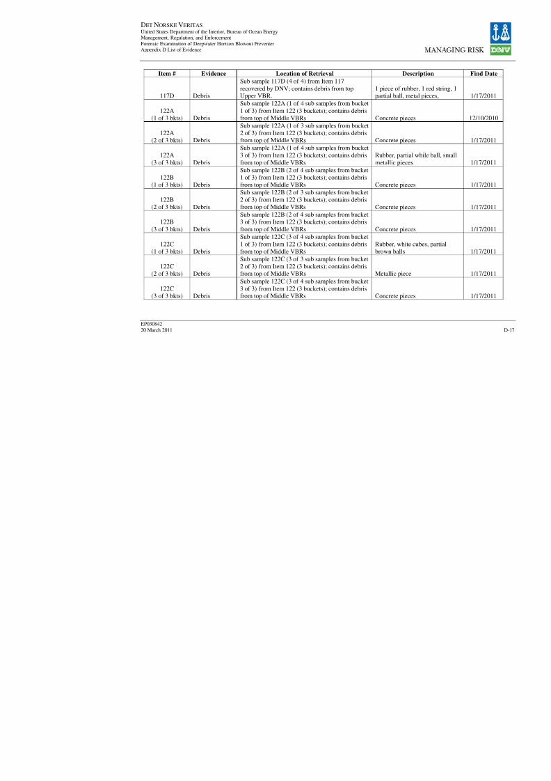
8/7/2019 DNV BOP report - Vol 2 (2)
http://slidepdf.com/reader/full/dnv-bop-report-vol-2-2 136/350

8/7/2019 DNV BOP report - Vol 2 (2)
http://slidepdf.com/reader/full/dnv-bop-report-vol-2-2 137/350

8/7/2019 DNV BOP report - Vol 2 (2)
http://slidepdf.com/reader/full/dnv-bop-report-vol-2-2 138/350
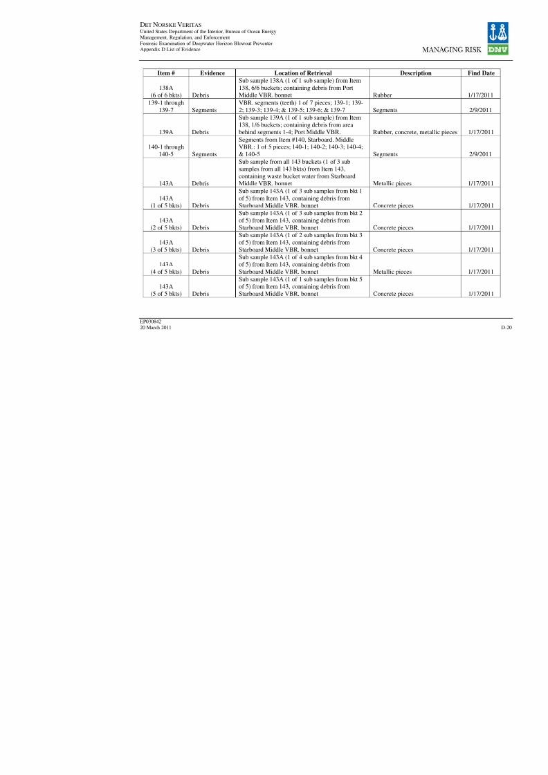
8/7/2019 DNV BOP report - Vol 2 (2)
http://slidepdf.com/reader/full/dnv-bop-report-vol-2-2 139/350
DET NORSKE VERITAS United States Department of the Interior, Bureau of Ocean EnergyManagement, Regulation, and Enforcement
Forensic Examination of Deepwater Horizon Blowout PreventerAppendix D List of Evidence
EP030842
20 March 2011
Item # Evidence Location of Retrieval Descriptio
138A(6 of 6 bkts) Debris
Sub sample 138A (1 of 1 sub sample) from Item
138, 6/6 buckets; containing debris from PortMiddle VBR. bonnet Rubber
139-1 through
139-7 Segments
VBR. segments (teeth) 1 of 7 pieces; 139-1; 139-
2; 139-3; 139-4; & 139-5; 139-6; & 139-7 Segments
139A Debris
Sub sample 139A (1 of 1 sub sample) from Item
138, 1/6 buckets; containing debris from areabehind segments 1-4; Port Middle VBR. Rubber, concrete, met
140-1 through
140-5 Segments
Segments from Item #140, Starboard. MiddleVBR.: 1 of 5 pieces; 140-1; 140-2; 140-3; 140-4;
& 140-5 Segments
143A Debris
Sub sample from all 143 buckets (1 of 3 sub
samples from all 143 bkts) from Item 143,
containing waste bucket water from StarboardMiddle VBR. bonnet Metallic pieces
143A
(1 of 5 bkts) Debris
Sub sample 143A (1 of 3 sub samples from bkt 1
of 5) from Item 143, containing debris from
Starboard Middle VBR. bonnet Concrete pieces
143A
(2 of 5 bkts) Debris
Sub sample 143A (1 of 3 sub samples from bkt 2
of 5) from Item 143, containing debris from
Starboard Middle VBR. bonnet Concrete pieces
143A
(3 of 5 bkts) Debris
Sub sample 143A (1 of 2 sub samples from bkt 3
of 5) from Item 143, containing debris from
Starboard Middle VBR. bonnet Concrete pieces
143A
(4 of 5 bkts) Debris
Sub sample 143A (1 of 4 sub samples from bkt 4
of 5) from Item 143, containing debris from
Starboard Middle VBR. bonnet Metallic pieces
143A
(5 of 5 bkts) Debris
Sub sample 143A (1 of 1 sub samples from bkt 5
of 5) from Item 143, containing debris from
Starboard Middle VBR. bonnet Concrete pieces

8/7/2019 DNV BOP report - Vol 2 (2)
http://slidepdf.com/reader/full/dnv-bop-report-vol-2-2 140/350
DET NORSKE VERITAS United States Department of the Interior, Bureau of Ocean EnergyManagement, Regulation, and Enforcement
Forensic Examination of Deepwater Horizon Blowout PreventerAppendix D List of Evidence
EP030842
20 March 2011
Item # Evidence Location of Retrieval Descriptio
143B Debris
Sub sample from all 143 buckets (2 of 3 sub
samples from all 143 bkts) from Item 143,containing waste bucket water from Starboard
Middle VBR. bonnet Concrete pieces
143B
(1 of 5 bkts) Debris
Sub sample 143B (2 of 3 sub samples from bkt 1
of 5) from Item 143, containing debris from
Starboard Middle VBR. bonnet Concrete pieces
143B
(2 of 5 bkts) Debris
Sub sample 143B (1 of 3 sub samples from bkt 2
of 5) from Item 143, containing debris from
Starboard Middle VBR. bonnet Rubber pieces
143B
(3 of 5 bkts) Debris
Sub sample 143B (2 of 2 sub samples from bkt 3
of 5) from Item 143, containing debris from
Starboard Middle VBR. bonnet Rubber
143B
(4 of 5 bkts) Debris
Sub sample 143B (2 of 4 sub samples from bkt 4of 5) from Item 143, containing debris from
Starboard Middle VBR. bonnet Concrete pieces
143C Debris
Sub sample from all 143 buckets (3 of 3 sub
samples from all 143 bkts) from Item 143,
containing waste bucket water from Starboard
Middle VBR. bonnet Concrete pieces
143C
(1 of 5 bkts) Debris
Sub sample 143B (3 of 3 sub samples from bkt 1
of 5) from Item 143, containing debris from
Starboard Middle VBR. bonnet Metallic pieces, rubbe
143C
(2 of 5 bkts) Debris
Sub sample 143C (3 of 3 sub samples from bkt 2
of 5) from Item 143, containing debris from
Starboard Middle VBR. bonnet Skid pad for pipe ram
143C
(4 of 5 bkts) Debris
Sub sample 143C (3 of 4 sub samples from bkt 4
of 5) from Item 143, containing debris from
Starboard Middle VBR. bonnet Concrete pieces

8/7/2019 DNV BOP report - Vol 2 (2)
http://slidepdf.com/reader/full/dnv-bop-report-vol-2-2 141/350
DET NORSKE VERITAS United States Department of the Interior, Bureau of Ocean EnergyManagement, Regulation, and Enforcement
Forensic Examination of Deepwater Horizon Blowout PreventerAppendix D List of Evidence
EP030842
20 March 2011
Item # Evidence Location of Retrieval Descriptio
143D(4 of 5 bkts) Debris
Sub sample 143D (4 of 4 sub samples from bkt 4
of 5) from Item 143, containing debris fromStarboard Middle VBR. bonnet Concrete pieces
148AA Debris
Sub sample 148AA (1 of 1 sub sample) from Item
148 recovered by DNV; contains debris collected
from top surface of drill pipe located in BOP "Junk shot"
148B-1 Debris
Sub sample 148B-1 (1 of 20 sub sample) from
Item 148 recovered by DNV; contains debris
collected from top surface of drill pipe located in
BOP "Junk shot"
148B-10 Debris
Sub sample 148B-10 (10 of 20 sub sample) from
Item 148 recovered by DNV; contains debris
collected from top surface of drill pipe located in
BOP "Junk shot"
148B-11 Debris
Sub sample 148B-11 (11 of 20 sub sample) from
Item 148 recovered by DNV; contains debris
collected from top surface of drill pipe located in
BOP "Junk shot"
148B-12 Debris
Sub sample 148B-12 (12 of 20 sub sample) from
Item 148 recovered by DNV; contains debris
collected from top surface of drill pipe located in
BOP "Junk shot"
148B-13 Debris
Sub sample 148B-13 (13 of 20 sub sample) from
Item 148 recovered by DNV; contains debris
collected from top surface of drill pipe located in
BOP "Junk shot"
148B-14 Debris
Sub sample 148B-14 (14 of 20 sub sample) from
Item 148 recovered by DNV; contains debris
collected from top surface of drill pipe located in
BOP "Junk shot"
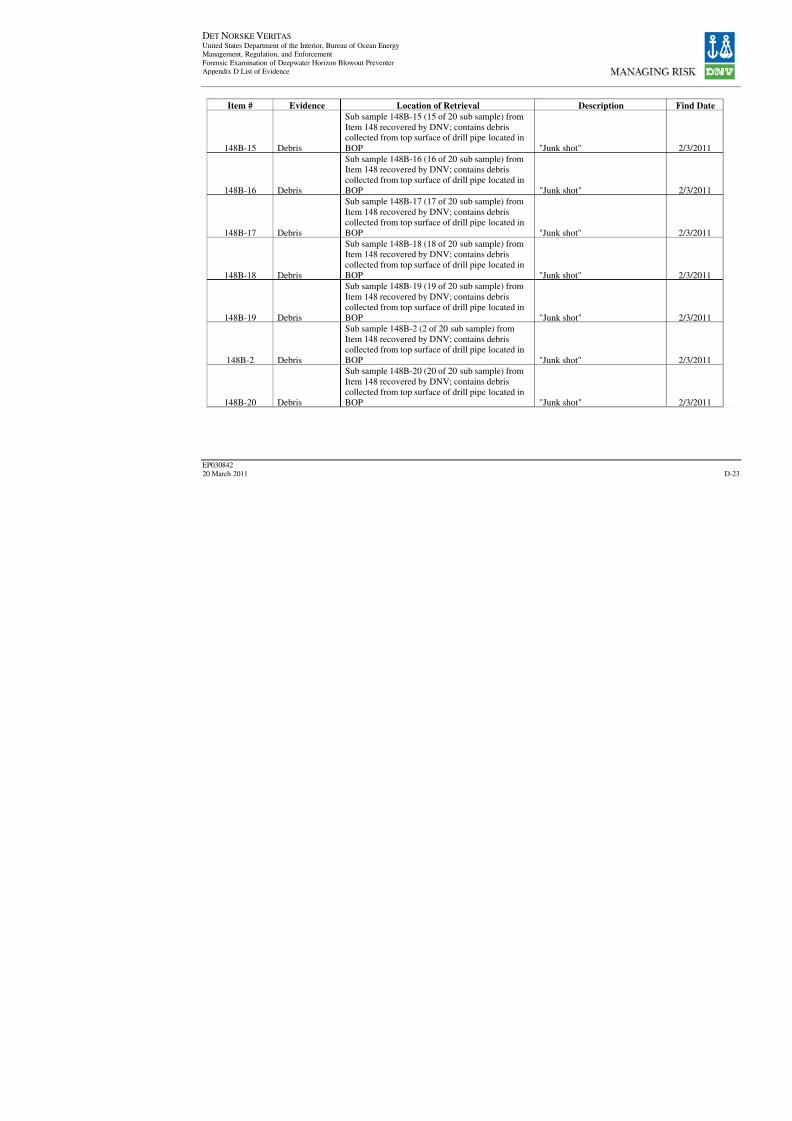
8/7/2019 DNV BOP report - Vol 2 (2)
http://slidepdf.com/reader/full/dnv-bop-report-vol-2-2 142/350
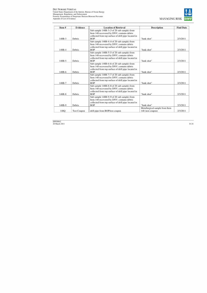
8/7/2019 DNV BOP report - Vol 2 (2)
http://slidepdf.com/reader/full/dnv-bop-report-vol-2-2 143/350
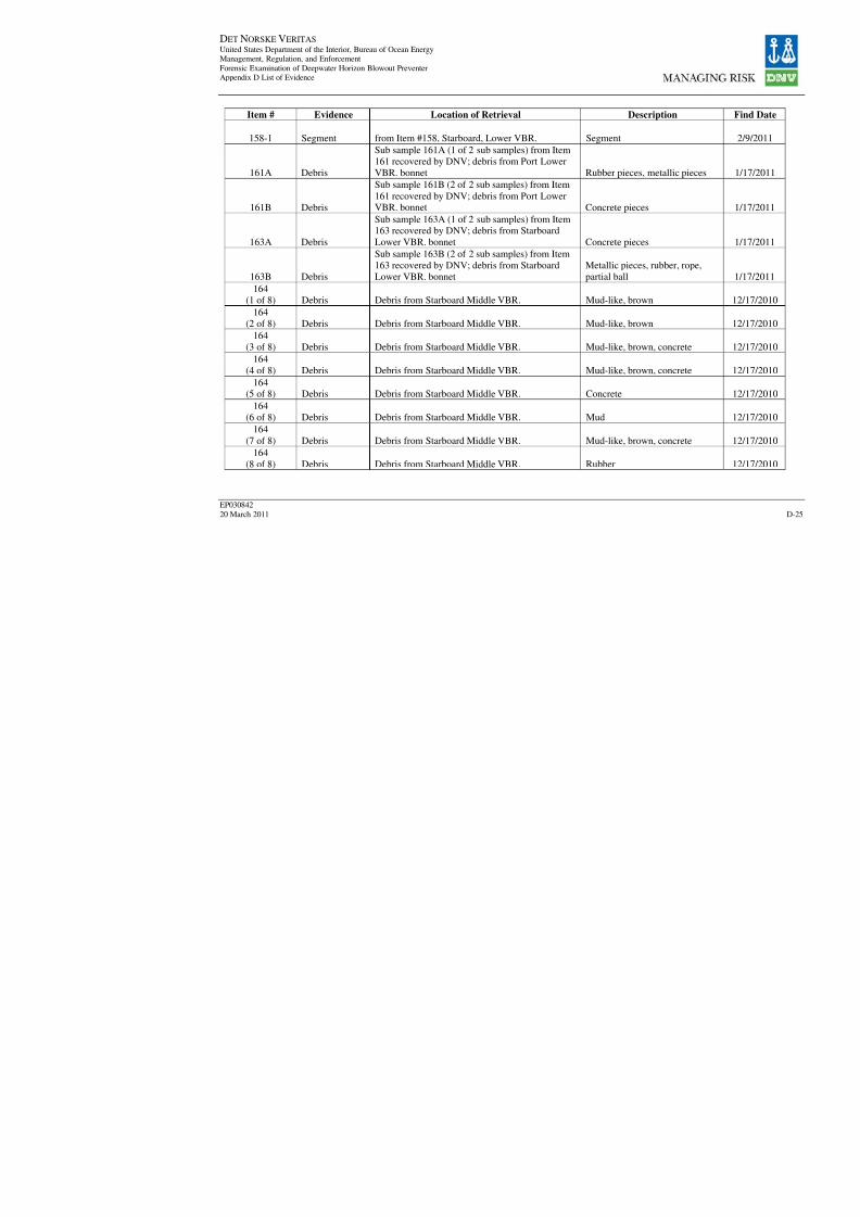
8/7/2019 DNV BOP report - Vol 2 (2)
http://slidepdf.com/reader/full/dnv-bop-report-vol-2-2 144/350
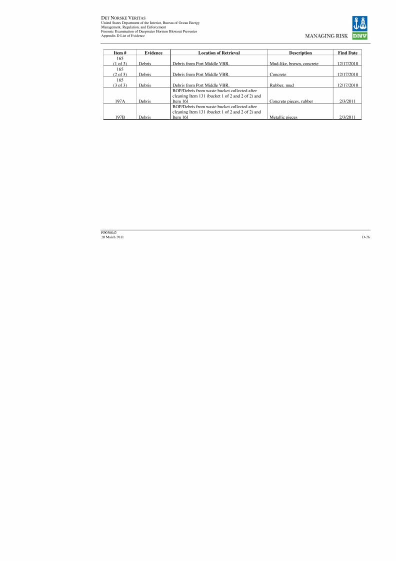
8/7/2019 DNV BOP report - Vol 2 (2)
http://slidepdf.com/reader/full/dnv-bop-report-vol-2-2 145/350

8/7/2019 DNV BOP report - Vol 2 (2)
http://slidepdf.com/reader/full/dnv-bop-report-vol-2-2 146/350
DET NORSKE VERITAS United States Department of the Interior, Bureau of Ocean Energy
Management, Regulation, and Enforcement
Forensic Examination of Deepwater Horizon Blowout Preventer
Volume II Appendices
EP030842
20 March 2011
APPENDIX E
SITE TEST RESULTS

8/7/2019 DNV BOP report - Vol 2 (2)
http://slidepdf.com/reader/full/dnv-bop-report-vol-2-2 147/350

8/7/2019 DNV BOP report - Vol 2 (2)
http://slidepdf.com/reader/full/dnv-bop-report-vol-2-2 148/350
DET NORSKE VERITAS United States Department of the Interior, Bureau of Ocean EnergyManagement, Regulation, and Enforcement
Forensic Examination of Deepwater Horizon Blowout PreventerAppendix E Site Test Results
EP03084220 March 2011 E-2
Bolt #1 Bolt #2 Bolt #3 Bolt #4
Ram
BonnetPressure
(psi)
Torque
(ft-lbs)
Pressure
(psi)
Torque
(ft-lbs)
Pressure
(psi)
Torque
(ft-lbs)
Pressure
(psi)
Torque
(ft-lbs)
BlindShear
Ram*
2,000 2,118 3,200 3,287 2,000 2,118 2,500 2,567
Lower
Pipe
Ram
3,200 3,287 3,000 3,174 5,600 5,812 2,400 2,464
Middle
Pipe
Ram*
4,200 4,333 4,000 4,239 3,600 3,704 3,800 3,704
Upper
Pipe
Ram
4,200 6,382 2,000 3,075 800 1,174 3,500 5,306
Casing
ShearRam
2,800 4,227 3,400 5,152 3,200 4,855 3,800 5,765
STBD Side
Blind
Shear
Ram
5,000 7,858 3,800 5,765 5,200 7,933 2,500* 2,567*
Note: All nuts broken out with IU-17XL Fitting unless denoted with a *.
* indicates that the nut was broken out with SU-11XL Fitting.
Table 3 Flex Joint Flange Bolts – Connection to Upper Annular
Bolt #
Pressure
(psi)
Torque
(Ft-lbs)
1 5,000 4,905
2 4,200 4,0933 3,400 3,323
4 4,800 4,702
5 3,400 3,323
6 4,400 4,296
7 3,800 3,701
8 4,800 4,702
9 3,100 3,039
10 4,600 4,499
11 4,200 4,093
12 4,600 4,499
13 3,400 3,323
14 5,000 4,90515 4,000 3,890
16 5,000 4,905
17 5,200 5,100
18 5,000 4,905
19 4,200 4,093
20 4,600 4,499
21 3,800 3,701
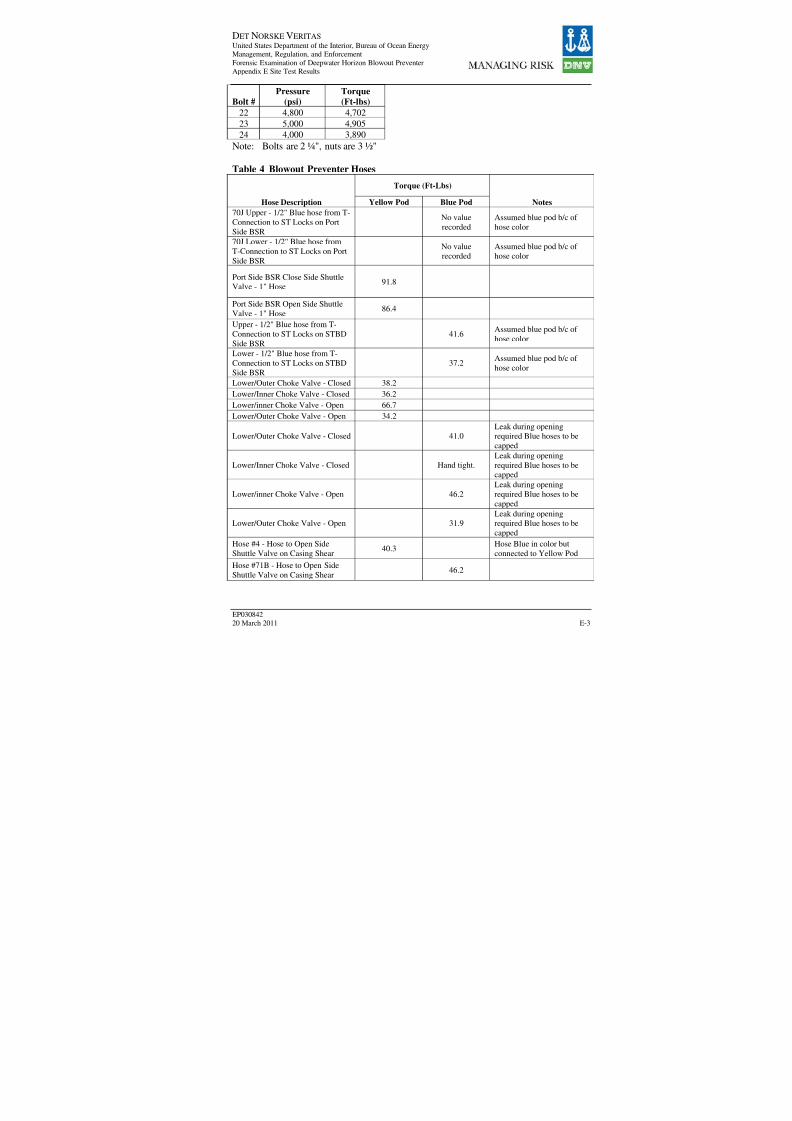
8/7/2019 DNV BOP report - Vol 2 (2)
http://slidepdf.com/reader/full/dnv-bop-report-vol-2-2 149/350
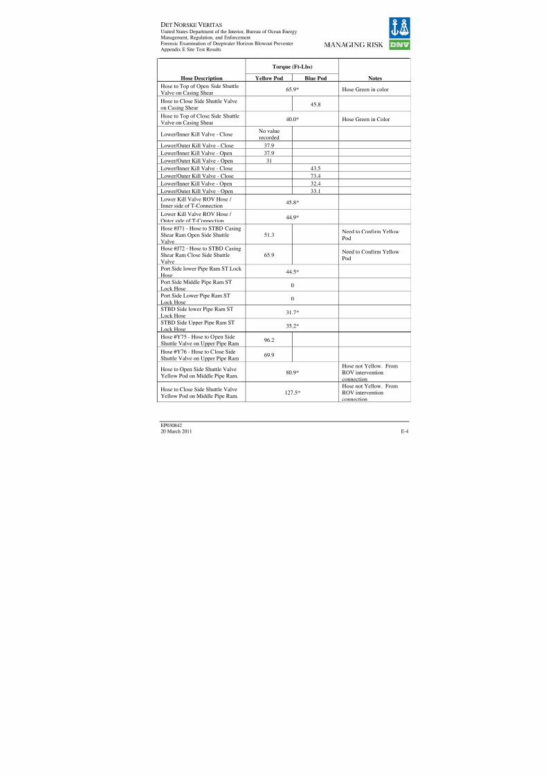
8/7/2019 DNV BOP report - Vol 2 (2)
http://slidepdf.com/reader/full/dnv-bop-report-vol-2-2 150/350

8/7/2019 DNV BOP report - Vol 2 (2)
http://slidepdf.com/reader/full/dnv-bop-report-vol-2-2 151/350
DET NORSKE VERITAS United States Department of the Interior, Bureau of Ocean EnergyManagement, Regulation, and Enforcement
Forensic Examination of Deepwater Horizon Blowout PreventerAppendix E Site Test Results
EP03084220 March 2011 E-5
Torque (Ft-Lbs)
Hose Description Yellow Pod Blue Pod Notes
Hose #68Y - Hose to Close SideShuttle Valve on Lower Pipe Ram
119.2
Hose #67Y - Hose to Open Side
Shuttle Valve on Lower Pipe Ram56.4
BOP Stack accumulator discharge
hose129.9
Hose from HP Shear Panel to BSR
(Green)113.7
Hose #103Y 39.2
Hose (Green) from Autoshear
valve to connection on HP Shear
Panel – at HP Shear Panel
40.8
Hose #99Y – From HP Shear Panel
to CSR Close – at HP Shear Pane.41.0
Hose #121Y – From Autoshear
Arm Shuttle valve to Autoshear
Panel
43.3
Hose #121Y – From Autoshear
Panel to Autoshear Valve – At
Autoshear Panel
48.2
Hose #122Y – From Autoshear
Disarm Shuttle Valve to Autoshear
Panel
34.6
Hose #93Y – Upper Inner Choke
Valve Open32.0
Hose #85Y – Upper Inner Kill
Valve Open27.0
ROV Panel Hose – Pipe Ram
Close41.0
ROV Panel Hose – Shear Ram
Close47.6
Hose #82Y – Accumulator Charge
Hose35.4
* indicates that the hose is not specific to either the Yellow Pod or the Blue Pod
Table 5 Actuator Screw Subassembly Bolts (LMRP)
Bolt # Torque (Ft-lbs)
1 112.3
2 59.1
3 0.0
4 0.0

8/7/2019 DNV BOP report - Vol 2 (2)
http://slidepdf.com/reader/full/dnv-bop-report-vol-2-2 152/350
DET NORSKE VERITAS United States Department of the Interior, Bureau of Ocean EnergyManagement, Regulation, and Enforcement
Forensic Examination of Deepwater Horizon Blowout PreventerAppendix E Site Test Results
EP03084220 March 2011 E-6
Table 6 Lower Marine Riser Package Hoses
Breakout Torque Ft-Lbs
Hose Description Yellow Pod Blue Pod Notes
Hose #44 - Hose to Lower Annular
Closed Side Shuttle Valve107.5
Hose to Lower Annular Closed Side
Shuttle Valve0
Hose from an ROV
intervention connection
Hose #13B - Hose to Lower Annular
Open Side Shuttle Valve201.2
Hose to Lower Annular Open Side
Shuttle Valve101.7
Label partially obscured, read
"3Y"
Hose to Upper Annular Closed Side
Shuttle Valve126.6
Hose to Upper Annular Closed SideShuttle Valve
0.0 Label partially obscured, read"2Y"
Hose to Upper Annular Open Side
Shuttle Valve211.9
Plate that hose is connected to
is labeled "11"
Hose to Upper Annular Open Side
Shuttle Valve0.0
Hose from 15-gal. accumulator to
Upper Annular Close Shuttle Valve57.0
Pilot line fitting on top of LMRP
accumulator dump valve15
Flexible Hose for blue pod supply
from rigid conduit264.6
Hot line supply hose to rigid conduitmanifold
119.9
• indicates that the hose is not specific to either the Yellow Pod or the Blue Pod
Table 7 Pod Hoses
Breakout
Torque (ft-lbs)
Hose DescriptionYellow
Pod
Blue
Pod Notes
Hot Stab Hose (removed to facilitate removal of pod topplates) 5 5
Tubing 103 (Between Solenoid and Hydraulic side) 5
Tubing 103 (Between Solenoid and Hydraulic side) 0
Slightly
Loose
Tubing 121 (Between Solenoid and Hydraulic side) 5
Tubing 103 (Between Solenoid and Hydraulic side) 5
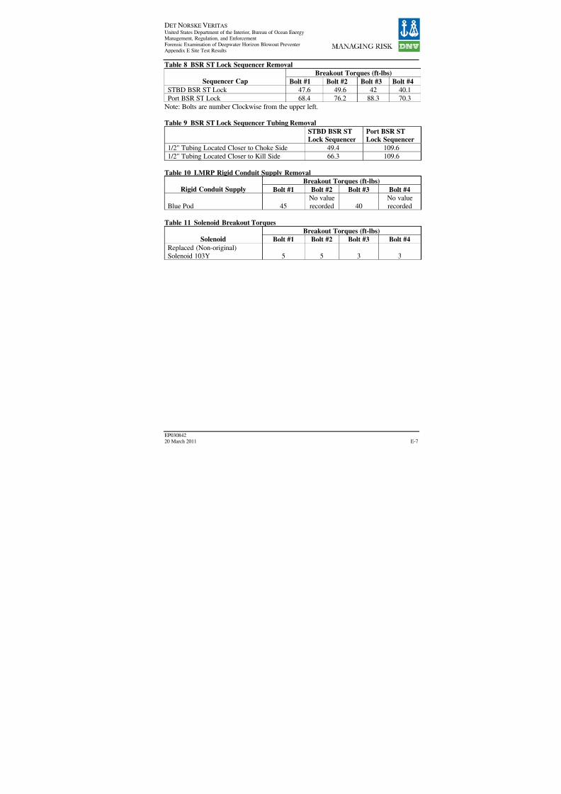
8/7/2019 DNV BOP report - Vol 2 (2)
http://slidepdf.com/reader/full/dnv-bop-report-vol-2-2 153/350
DET NORSKE VERITAS United States Department of the Interior, Bureau of Ocean EnergyManagement, Regulation, and Enforcement
Forensic Examination of Deepwater Horizon Blowout PreventerAppendix E Site Test Results
EP03084220 March 2011 E-7
Table 8 BSR ST Lock Sequencer Removal
Breakout Torques (ft-lbs)
Sequencer Cap Bolt #1 Bolt #2 Bolt #3 Bolt #4
STBD BSR ST Lock 47.6 49.6 42 40.1Port BSR ST Lock 68.4 76.2 88.3 70.3
Note: Bolts are number Clockwise from the upper left.
Table 9 BSR ST Lock Sequencer Tubing Removal
STBD BSR STLock Sequencer
Port BSR STLock Sequencer
1/2" Tubing Located Closer to Choke Side 49.4 109.6
1/2" Tubing Located Closer to Kill Side 66.3 109.6
Table 10 LMRP Rigid Conduit Supply Removal
Breakout Torques (ft-lbs)Rigid Conduit Supply Bolt #1 Bolt #2 Bolt #3 Bolt #4
Blue Pod 45
No value
recorded 40
No value
recorded
Table 11 Solenoid Breakout Torques
Breakout Torques (ft-lbs)
Solenoid Bolt #1 Bolt #2 Bolt #3 Bolt #4
Replaced (Non-original)
Solenoid 103Y 5 5 3 3
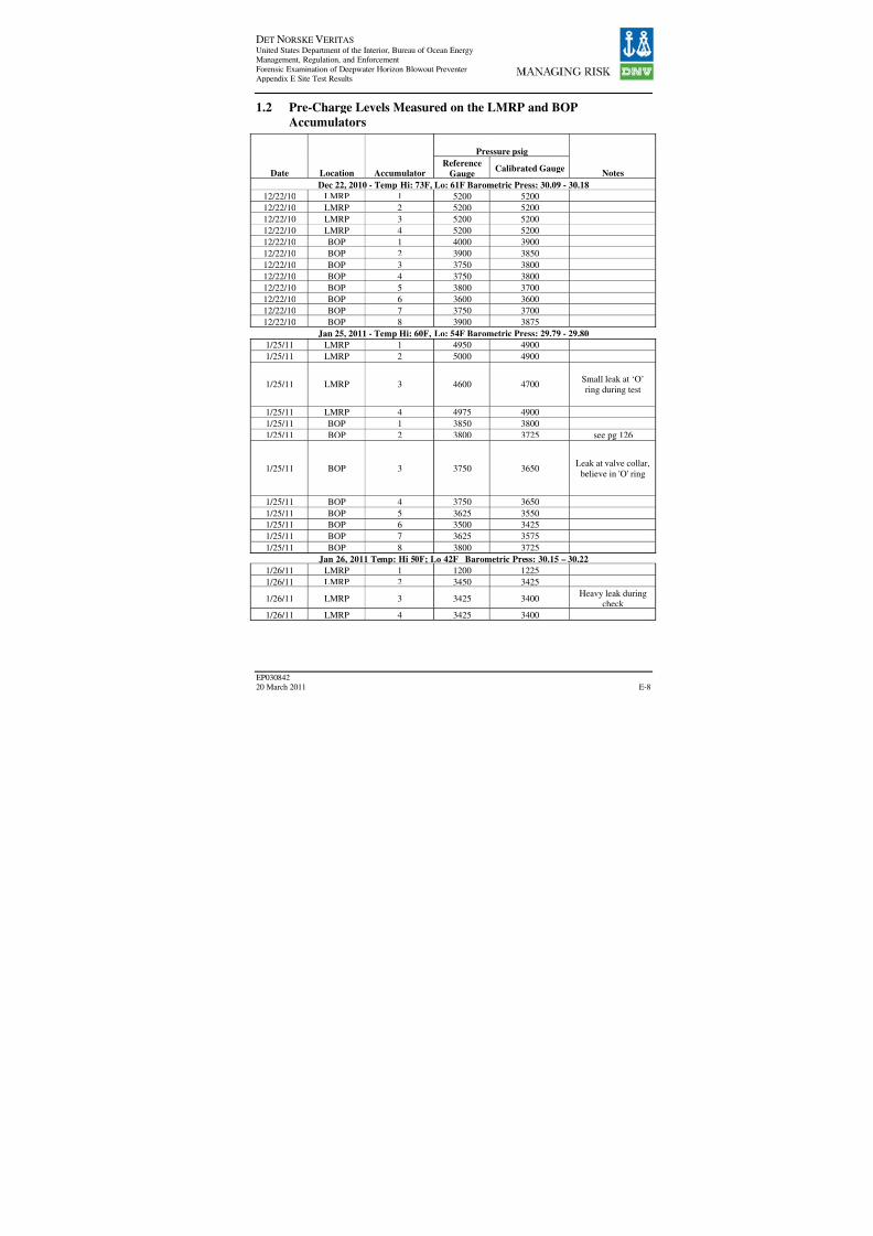
8/7/2019 DNV BOP report - Vol 2 (2)
http://slidepdf.com/reader/full/dnv-bop-report-vol-2-2 154/350

8/7/2019 DNV BOP report - Vol 2 (2)
http://slidepdf.com/reader/full/dnv-bop-report-vol-2-2 155/350
DET NORSKE VERITAS United States Department of the Interior, Bureau of Ocean EnergyManagement, Regulation, and Enforcement
Forensic Examination of Deepwater Horizon Blowout PreventerAppendix E Site Test Results
EP03084220 March 2011 E-9
Pressure psig
Date Location AccumulatorReference
GaugeCalibrated Gauge
Notes
Reference
GaugeCalibrated Gauge
Jan 27, 2011 Temp: Hi 57F; Lo, 47F Barometric Press: 30.12 - 30.21
1/27/11 LMRP 1 1200 1200
1/27/11 LMRP 2 3425 3375
1/27/11 LMRP 3 2250 2300 Leak during test
1/27/11 LMRP 3 2350 2375Recheck-heavy leak
at ‘O’ ring
1/27/11 LMRP 4 3450 3400
1/27/11 BOP 1 3625 3600Leak at ‘O’ ring
during test
1/27/11 BOP 2 3800 3750
1/27/11 BOP 3 3800 37001/27/11 BOP 4 3800 3725
1/27/11 BOP 5 3750 3650
1/27/11 BOP 6 3550 3500
1/27/11 BOP 7 3675 3675
1/27/11 BOP 8 3850 3825
6
8
7
5
3
4
2
1
BOP Lower Section
Starboard
Port
Kill Choke
1
2
3
4
LMRP
Starboard
Port
Kill Choke
6
8
7
5
3
4
2
1
BOP Lower Section
Starboard
Port
Kill Choke
6
8
7
5
3
4
2
1
BOP Lower Section
Starboard
Port
Kill Choke
1
2
3
4
LMRP
Starboard
Port
Kill Choke
1
2
3
4
LMRP
Starboard
Port
Kill Choke

8/7/2019 DNV BOP report - Vol 2 (2)
http://slidepdf.com/reader/full/dnv-bop-report-vol-2-2 156/350
DET NORSKE VERITAS United States Department of the Interior, Bureau of Ocean EnergyManagement, Regulation, and Enforcement
Forensic Examination of Deepwater Horizon Blowout PreventerAppendix E Site Test Results
EP03084220 March 2011 E-10
1.3 AMF/Deadman Test Measurements
On February 7, 2011, a test of the AMF/Deadman functions of the lower section of theBOP was completed. Below are the results of various measurements taken with respectto that test. Certain measurements were repeated on 8/Feb to confirm the data recorded
on February 7. That data is provided on the attached page.
This test was undertaken with the Pre-Charge levels on the eight (8) – eighty (80) gallon
accumulators in their ‘As Is’ condition. That information was previously provided. For
quick reference those Pre-Charge levels were on the order of 3500 – 3800 psig.
Where a number or value is provided in parentheses in a particular row, that number has
been provided as a reference value for that particular function or measurement
Remainder of this page left blank.

8/7/2019 DNV BOP report - Vol 2 (2)
http://slidepdf.com/reader/full/dnv-bop-report-vol-2-2 157/350
DET NORSKE VERITAS United States Department of the Interior, Bureau of Ocean EnergyManagement, Regulation, and Enforcement
Forensic Examination of Deepwater Horizon Blowout PreventerAppendix E Site Test Results
EP03084220 March 2011 E-11
1.3.1 February 7 2011 As-Is Pre-Charge Measurements
Data to Record for AMF/Deadman System: Measured Value
1. Red HPU Reservoir Level Start/Finish (gal.) 3
2. Triplex Tote Level – Start/Finish (in.) 47.5 / 23.25
3. Pre-charge Condition – Note data previously provided As Is
4. BSR Tank Level / Choke and Kill Tank Level (in.) (pre-test) 0 / 0
5. Volume Required to fill accumulators – 1st Fill (gal.) 206.1
6. Volume Required to fill accumulators – 2nd Fill (gal.) 4.25
7. Accumulator Pressure (5,000 psig) 5,000
8. HPU to Y103 Gauge Pressure (3,000 psig) 3,000
9. Autoshear Valve Gauge Pressure (3,000 psig) 0
10. BSR Close - Gauge Pressure (4,000 psig) 3,850
11. ST Lock Regulator Gauge Pressure – Port (1,500 psig) 1,525
12. ST Lock Regulator Gauge Pressure – Starboard (1,500 psig) 1,500
13. Time to Close BSR Rams (sec.) 23
14. BSR Rams closed (fully) yes
15. Fluid discharge from BSR Open Hose yes
16. Approximate Volume discharged from BSR Open Hose (in.) 14 3/4 (to beconfirmed)\
Measured again on 8/Feb (in.) 14-5/8
Approximate Volume discharged from BSR (gal.) 26.4
17. Inner Upper/Lower Choke/Kill Valves Closed yes
18. Fluid discharge from Choke/Kill Open Hoses yes
19. Approximate Volume discharged from Choke/Kill (in./gal) 1.5 in/12.75 gal (error)
Measured again on 8/Feb 1.25/2.3 gal
20. Port Side BSR ST Lock Position (in.) 3-3/8
21. Starboard Side BSR ST Lock Position (in.) 3-5/8
22. Fluid discharge from ST Lock Open Hose yes
23. Accumulator Dump Volume Unable to confirm
Anomalies, Leaks non-functionality, Notes:
Final accumulator gauge pressure was 4,475 psig before venting.

8/7/2019 DNV BOP report - Vol 2 (2)
http://slidepdf.com/reader/full/dnv-bop-report-vol-2-2 158/350
DET NORSKE VERITAS United States Department of the Interior, Bureau of Ocean EnergyManagement, Regulation, and Enforcement
Forensic Examination of Deepwater Horizon Blowout PreventerAppendix E Site Test Results
EP03084220 March 2011 E-12
1.3.2 February 17, 2011 Reduced Pre-charge Measurements
No. Description Value
1 Red HPU Reservoir Level Start / Finish (gal.) 521 / 216
2 Triplex Tote Level – Start / Finish (in.) 62-1/16 / 44-1/16
3 Pre-charge Condition Reduced
4 BSR Tank Level / Choke and Kill Tank Level (in.) 0/0
5 Volume Required to fill accumulators – 1st Fill (gal.) 458
6 Volume Required to fill accumulators – 2nd Fill (gal.) n/a
7 Accumulator Pressure (5,000 psig) 4,975
8 HPU to B103 Gauge Pressure (3,000 psig) 3,400
9 Autoshear Valve Gauge Pressure (3,000 psig) 0
10 BSR Close Gauge Pressure (4,000 psig) 3,900
11 ST Lock Regulator Gauge Pressure – Port (1,500 psig) 1,450
12 ST Lock Regulator Gauge Pressure – Starboard (1,500 psig) 1,460
13 Time to close BSR Rams (sec.) 24
14 BSR Rams closed (fully) Yes
15 Fluid discharge from BSR Open Hose Yes
16 Approximate Volume discharged from BSR Open Hose (in./gal.) 14 / 25.3
17 Inner Upper/Lower Choke/Kill Valves Closed Yes
18 Fluid discharge from Choke/Kill Open Hoses No
19 Approximate Volume discharged from Choke/Kill (gal.) 0
20 Accumulator Pressure Following Function (psig)
21 H.P. Blind Shear Vent – During BSR Retract (in. / gal.) 13 / 23.5
22 Accumulator Dump Volume (in. / gal.) 36.75 / 312.4
23 H.P. Blind Shear Vent – After Function (in. / gal.) 8.375 / 71.2
24 Blind Shear Ram Retract Volume (start / finish / total) (gal.) 216 / 190 / 26
Notes: Check valve from BOP Stack Accumulators did not leak
H.P. Blind Shear vent initiated after test due to a leak on the hose leading from HPU toB103. Vent stopped by reapplying pilot pressure. A total 8.375-inches, which is equivalent to71.2-gallons was dumped during the vent.

8/7/2019 DNV BOP report - Vol 2 (2)
http://slidepdf.com/reader/full/dnv-bop-report-vol-2-2 159/350
DET NORSKE VERITAS United States Department of the Interior, Bureau of Ocean EnergyManagement, Regulation, and Enforcement
Forensic Examination of Deepwater Horizon Blowout PreventerAppendix E Site Test Results
EP03084220 March 2011 E-13
1.3.3 February 18, 2011 Reduced Pre-charge Measurements
No. Description Value
1 Volume from Red HPU (gal.) 320
2 Triplex Tote Level – Start / Finish (in.) 61-¼ / 46-3/8
3 Pre-charge Condition Reduced
4 BSR Tank Level / Choke and Kill Tank Level (in.) 0 / 0
5 Volume Required to fill accumulators – 1st Fill (gal.) 4461
6 Volume Required to fill accumulators – 2nd Fill (gal.) 0
7 Accumulator Pressure (5,000 psig) 5,000
8 HPU to B103 Gauge Pressure (3,000 psig) 3,000
9 Autoshear Valve Gauge Pressure (3,000 psig) 0
10 BSR Close Gauge Pressure (4,000 psig) 3,800
11 ST Lock Regulator Gauge Pressure – Port (1,500 psig) 1,400
12 ST Lock Regulator Gauge Pressure – Starboard (1,500 psig) 1,400
13 Time to close BSR Rams (sec.) 24
14 BSR Rams closed (fully) Yes
15 Fluid discharge from BSR Open Hose Yes
16 Approximate Volume discharged from BSR Open Hose(in./gal.)
13.5 / 24.4
17 Inner Upper/Lower Choke/Kill Valves Closed Yes
18 Fluid discharge from Choke/Kill Open Hoses No
19 Approximate Volume discharged from Choke/Kill (gal.) 0
20 Accumulator Pressure Following Function (psig) 4,125
21 H.P. Blind Shear Vent – During BSR Retract (in. / gal.) 15-1/8 / 27.4
22 Accumulator Dump Volume (in. / gal.) 46.5 / 395.3
23 H.P. Blind Shear Vent – After Function (in. / gal.) 0 / 0Notes:1Calculated from #1 and #2.
No bleed back from BOP Stack Accumulators

8/7/2019 DNV BOP report - Vol 2 (2)
http://slidepdf.com/reader/full/dnv-bop-report-vol-2-2 160/350
DET NORSKE VERITAS United States Department of the Interior, Bureau of Ocean EnergyManagement, Regulation, and Enforcement
Forensic Examination of Deepwater Horizon Blowout PreventerAppendix E Site Test Results
EP03084220 March 2011 E-14
1.4 HP Casing Shear Pressure Decay
On January 31 a leak in the High Pressure Casing Shear regulator mounted on the back of
the High Pressure Panel was identified.
The hydraulic side of the eight 80-gallon Stack Accumulators was pressurized to 3700psig at approx. 18:22. The pressure to the Accumulators was then shut-in. The pre-
charge levels were as previously recorded and reported.
One video camera was arranged to monitor and record changes in Accumulator pressure.
A second camera was arranged to monitor the actual leak from the Regulator. Further a
means to capture the fluid leaking from the Regulator was set-up.
From the period of about 17:30 (31/Jan) (when the fluid capture arrangements werecomplete) through to 08.10 (1/Feb) a total volume of approximately 1.5 gallons of fluid
was captured. Table 1 below summarizes the pressure readings taken from the video-recordings of the pressure gauge. Time ‘0’ (zero) equates to 18.22 hours (31/Jan).
Table 1
Time(min)
Pressure(psig)
0 3700
30 3700
60 3500
90 3250
120 2900
150 2500
180 2300
210 2000
240 1800
270 1650
300 1500
330 1300
360 1200
390 1050
420 950
450 850
480 800
510 750540 650
570 600
600 550
630 450
660 450
690 450
720 400

8/7/2019 DNV BOP report - Vol 2 (2)
http://slidepdf.com/reader/full/dnv-bop-report-vol-2-2 161/350
DET NORSKE VERITAS United States Department of the Interior, Bureau of Ocean EnergyManagement, Regulation, and Enforcement
Forensic Examination of Deepwater Horizon Blowout PreventerAppendix E Site Test Results
EP03084220 March 2011 E-15
1.5 Autoshear Test Measurements
1.5.1 February 8, 2011 – As-Is Pre-Charge
No. Description Value
1 Red HPU Reservoir Level Start / Finish (gal.) 221 / 221
2 Triplex Tote Level – Start / Finish (in.) 61.5 / 46.25
3 Pre-charge Condition As-is
4 BSR Tank Level / Choke and Kill Tank Level (in.) 0 / 0
5 Volume Required to fill accumulators – 1st Fill (gal.) 129.6*
6 Volume Required to fill accumulators – 2nd Fill (gal.) N/A
7 Accumulator Pressure (5,000 psig) 5,000 (5,600 spike)
8 HPU to Y103 Gauge Pressure (3,000 psig) 3,000
9 Autoshear Valve Gauge Pressure (3,000 psig) 3,150
10 BSR Close Gauge Pressure (4,000 psig) 3,800
11 ST Lock Regulator Gauge Pressure – Port (1,500 psig) 1,500
12 ST Lock Regulator Gauge Pressure – Starboard (1,500 psig) 1,500
13 Time to close BSR Rams (sec.) 28
14 BSR Rams closed (fully) Yes
15 Fluid discharge from BSR Open Hose Yes
16Approximate Volume discharged from BSR Open Hose(in./gal.)
15.5 / 28.1
17 Inner Upper/Lower Choke/Kill Valves Closed Yes
18 Fluid discharge from Choke/Kill Open Hoses No
19 Approximate Volume discharged from Choke/Kill (gal.) 0
20 Port Side BSR ST Lock Position (in.) 3-5/16
21 Starboard Side BSR ST Lock Position (in.) 3-5/8
22 Accumulator Dump Volume (in. / gal.) 13-1/8 / 111.6
23 H.P. Blind Shear Vent during Ram Retraction (in. / gal.) 31.3 / 56.6
Notes:*Based on tote level recorded in No. 2. Value might not be accurate due to leak on TriplePump bypass valve
-4,500 psig Accumulator Pressure following function.

8/7/2019 DNV BOP report - Vol 2 (2)
http://slidepdf.com/reader/full/dnv-bop-report-vol-2-2 162/350
DET NORSKE VERITAS United States Department of the Interior, Bureau of Ocean EnergyManagement, Regulation, and Enforcement
Forensic Examination of Deepwater Horizon Blowout PreventerAppendix E Site Test Results
EP03084220 March 2011 E-16
1.5.2 February 11, 2011 – Reduced Pre-Charge
No. Description Value
1 Red HPU Reservoir Level Start / Finish (gal.) 196/1951
2 Triplex Tote Level – Fluid Delivered (in. / gal.) 48 / 408
3 Pre-charge Condition Reduced
4 BSR Tank Level / Choke and Kill Tank Level (in.) 0 / 0
5 Volume Required to fill accumulators – 1st Fill (gal.) 4082
6 Volume Required to fill accumulators – 2nd Fill (gal.) n/a
7 Accumulator Pressure (5,000 psig) 5,000
8 HPU to Y121 Gauge Pressure (3,000 psig) 3,100
9 Autoshear Valve Gauge Pressure (3,000 psig) 3,150
10 BSR Close Gauge Pressure (4,000 psig) 3,825
11 ST Lock Regulator Gauge Pressure – Port (1,500 psig) 1,500
12 ST Lock Regulator Gauge Pressure – Starboard (1,500 psig) 1,500
13 Time to close BSR Rams (sec.) 26
14 BSR Rams closed (fully) Yes
15 Fluid discharge from BSR Open Hose Yes
16Approximate Volume discharged from BSR Open Hose(in./gal.) 16.5 / 29.9
17 Inner Upper/Lower Choke/Kill Valves Closed Yes
18 Fluid discharge from Choke/Kill Open Hoses No
19 Approximate Volume discharged from Choke/Kill (gal.) 0
20 Port Side BSR ST Lock Position (in.) 3-5/16
21 Starboard Side BSR ST Lock Position (in.) 3 ½
22 Accumulator Dump Volume (in. / gal.) Not Captured3
23 Accumulator Pressure Following Function (psig) 4,000
Notes:1Volume used for activating Autoshear2Volume based on #23Hose did not stay in tote.
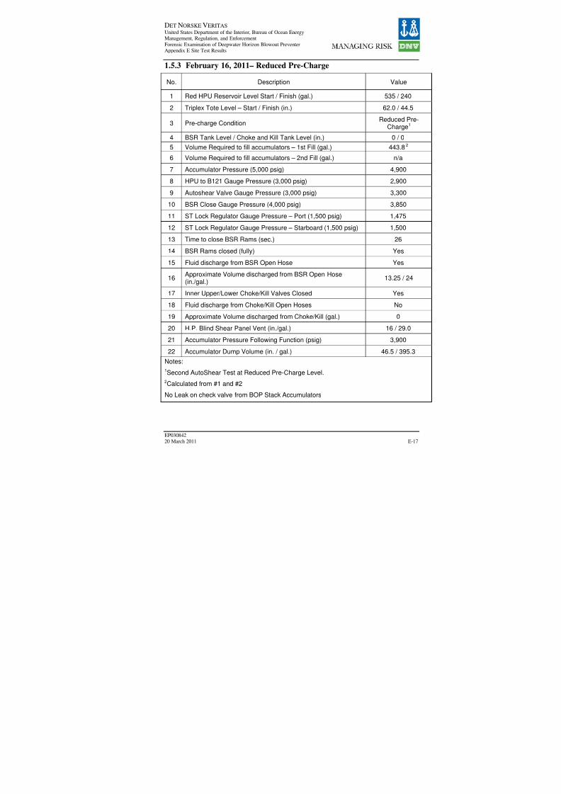
8/7/2019 DNV BOP report - Vol 2 (2)
http://slidepdf.com/reader/full/dnv-bop-report-vol-2-2 163/350
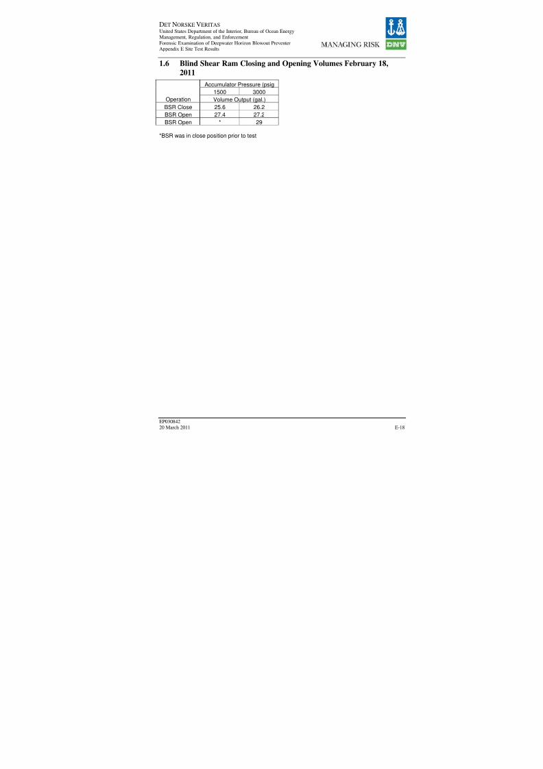
8/7/2019 DNV BOP report - Vol 2 (2)
http://slidepdf.com/reader/full/dnv-bop-report-vol-2-2 164/350

8/7/2019 DNV BOP report - Vol 2 (2)
http://slidepdf.com/reader/full/dnv-bop-report-vol-2-2 165/350

8/7/2019 DNV BOP report - Vol 2 (2)
http://slidepdf.com/reader/full/dnv-bop-report-vol-2-2 166/350

8/7/2019 DNV BOP report - Vol 2 (2)
http://slidepdf.com/reader/full/dnv-bop-report-vol-2-2 167/350
DET NORSKE VERITAS United States Department of the Interior, Bureau of Ocean EnergyManagement, Regulation, and Enforcement
Forensic Examination of Deepwater Horizon Blowout PreventerAppendix F Comprehensive Timeline
EP030842
20 March 2011
Perspective = BP Perspective = Cameron Perspective = Regulatory Sour
Date Time Event Ref. Event Ref. Event Re
6/15/91 Cameron Collet Connector- Self Locking Design
EngineeringBulletin
10/31/91
Recommendations for
Field Testing of theCameron D AnnularBlowout Preventer -recommend open / close
on pipe daily
EngineeringBulletin
2/8/92
D Seal - D Shaped SealUsed as an OperationalReplacement for theStandard Lip Seal in
Annular BOPs
EngineeringBulletin
3/22/93
Inspection and Servicing
Modular BOP Control PodStingers and Receptacles -provides quarterly, semi-
annual and annualinspections
EngineeringBulletin
11/29/93
Low Temperature Testingof VBRs - packers must
be "exercised"
EngineeringBulletin
11/30/94
Variable Bore Ram -
Engineering Data -estimated service life andhangoff capacity forvarious models
EngineeringBulletin
10/29/98
Shear Ram Product Line -
includes original ram
specs for various models,but pre-TL
Engineering
Bulletin
5/20/99Sequence Valve On SiteInspection Procedure
EngineeringBulletin
Aug-99TOI performed HAZOPon BOP Control System
31
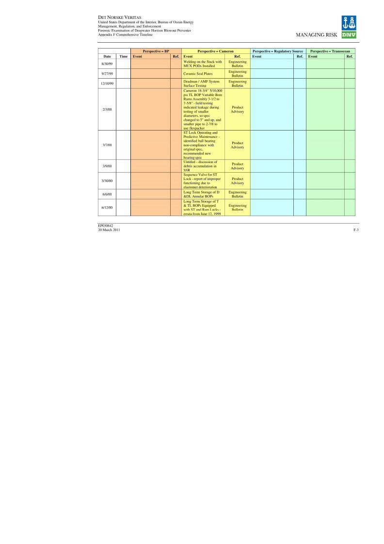
8/7/2019 DNV BOP report - Vol 2 (2)
http://slidepdf.com/reader/full/dnv-bop-report-vol-2-2 168/350

8/7/2019 DNV BOP report - Vol 2 (2)
http://slidepdf.com/reader/full/dnv-bop-report-vol-2-2 169/350
DET NORSKE VERITAS United States Department of the Interior, Bureau of Ocean EnergyManagement, Regulation, and Enforcement
Forensic Examination of Deepwater Horizon Blowout PreventerAppendix F Comprehensive Timeline
EP030842
20 March 2011
Perspective = BP Perspective = Cameron Perspective = Regulatory Sour
Date Time Event Ref. Event Ref. Event Re
6/15/00
Bearing, Overhauling Nut,ST Lock - report of premature wear to
overhaul nut threads, newbearings available
Product
Advisory
8/28/00
Shuttle Valves DrillingMultiplex BOP ControlSystems - unclearphotocopy
ProductAdvisory
9/11/00
LMRP & Wellhead
Connector FunctionLockout - unintentional
disconnection of LMRPdue to human error, seeSafety Advisory #186 andNTL No2000-G07
Product
Advisory
9/29/00Existing Diverter PackerCircuits
EngineeringBulletin
10/6/00
Drilling Multiplex BOPControl System Mark IIControl Pod Subsea
Electronic Module PowerSupply - 5 V poweroperating at near or aboverated capacity
Product
Advisory
2001
Deepwater Horizon wasbuilt…and employed a
15,000 psi BOPsystem."
19
Mar-01

8/7/2019 DNV BOP report - Vol 2 (2)
http://slidepdf.com/reader/full/dnv-bop-report-vol-2-2 170/350
DET NORSKE VERITAS United States Department of the Interior, Bureau of Ocean EnergyManagement, Regulation, and Enforcement
Forensic Examination of Deepwater Horizon Blowout PreventerAppendix F Comprehensive Timeline
EP030842
20 March 2011
Perspective = BP Perspective = Cameron Perspective = Regulatory Sour
Date Time Event Ref. Event Ref. Event Re
Apr-01
"A qualification test of Deepwater HorizonBOP BSRs was
conducted at thesurface…, when a jointof 5.5 in., 21.9 ppf, S-135 drill pipe wassuccessfully sheared at
a shearing pressure of 2,900 psi, which isslightly greater than the
pressure predicted byCameron's shearingformula."
19
9/4/01
18-3/4" 15M TL BOP
Super Shear Ram Bonnets- two reported incidents of restricted closures,modification provided
EngineeringBulletin
9/4/01
18-3/4" 15M TL BOPSuper Shear Ram Retainer
Pins - incident reported of sheared pin, attributed tocorrosion, recommendedlubrication or corrosion
resistant coating
EngineeringBulletin
Nov-01
Pod subsea platemounted (SPM) valves.All 1 in. valves have
been changed out toupgrade 3/4 in. valve.
19
1/30/02MMS Inspection of DeepWater Horizon
9

8/7/2019 DNV BOP report - Vol 2 (2)
http://slidepdf.com/reader/full/dnv-bop-report-vol-2-2 171/350
DET NORSKE VERITAS United States Department of the Interior, Bureau of Ocean EnergyManagement, Regulation, and Enforcement
Forensic Examination of Deepwater Horizon Blowout PreventerAppendix F Comprehensive Timeline
EP030842
20 March 2011
Perspective = BP Perspective = Cameron Perspective = Regulatory Sour
Date Time Event Ref. Event Ref. Event Re
Mar-02
Pod flow meters -"Spare pod sent toCameron for upgrade to
install high-shock flowmeters"
19
3/6/02
Fuses in SubseaArchitecture - relates tofailures that may renderboth pods inoperable,
provide protection kits,see 006024 May 6, 2002
ProductAdvisory
3/6/02
Cooling Kits for Drillers
Control Panels - heatexpected to decreasecomponent life, providecooling kits that require100 psi air at 25 CFM
ProductAdvisory
3/13/02
ST Lock Brake Hub-
Global Marine Santa Fe -TL ram BOP ST partswith "discrepant toothprofile", replacement
offered
ProductAdvisory
3/13/02
ST Lock Brake Hub-Crosco - TL ram BOP STparts with "discrepanttooth profile", replacementoffered
ProductAdvisory
3/13/02
ST Lock Brake Hub -
Transocean Sedco Forex -TL ram BOP ST parts
with "discrepant toothprofile", replacementoffered, mention of Sovereign Explorer, DW
Navigator and DWExpedition
ProductAdvisory

8/7/2019 DNV BOP report - Vol 2 (2)
http://slidepdf.com/reader/full/dnv-bop-report-vol-2-2 172/350
DET NORSKE VERITAS United States Department of the Interior, Bureau of Ocean EnergyManagement, Regulation, and Enforcement
Forensic Examination of Deepwater Horizon Blowout PreventerAppendix F Comprehensive Timeline
EP030842
20 March 2011
Perspective = BP Perspective = Cameron Perspective = Regulatory Sour
Date Time Event Ref. Event Ref. Event Re
3/14/02
ST Lock Overhauling NutP/N 644682-03 - incidentof excessive thread wear
(see June 2000),recommended inspection546 cycles or 18 months,replacement offered, note3-67 ST Lock Inspection
in Manual
ProductAdvisory
3/29/02MMS Inspection of DeepWater Horizon
9
4/2/02
Super Shear Ram Retainer
Pin Part Number - incidentof SSR deformed / brokenretainer pin, replacementoffered, see EB Sept 2001
ProductAdvisory
4/22/02MMS Inspection of DeepWater Horizon
9
5/6/02
Fuses in Subsea
Architecture - report of single point electricalfailure rendering bothsubsea pods inoperable,
provide protection kits,see 086024 March 2002
ProductAdvisory
5/16/02
MMS Inspection of DeepWater Horizon - 2 INCSconcerning pit drill andmanhole
9
6/4/02MMS Inspection of DeepWater Horizon - follow upInspection form
9
6/5/02MMS Inspection of DeepWater Horizon
9
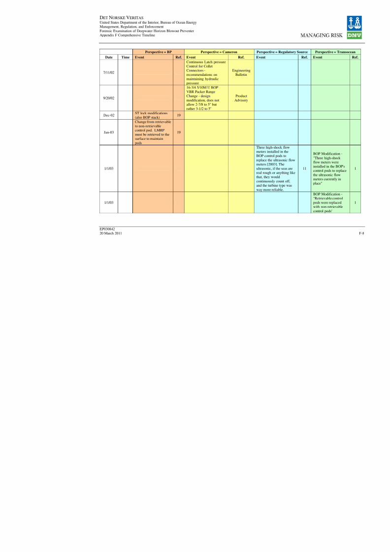
8/7/2019 DNV BOP report - Vol 2 (2)
http://slidepdf.com/reader/full/dnv-bop-report-vol-2-2 173/350
DET NORSKE VERITAS United States Department of the Interior, Bureau of Ocean EnergyManagement, Regulation, and Enforcement
Forensic Examination of Deepwater Horizon Blowout PreventerAppendix F Comprehensive Timeline
EP030842
20 March 2011
Perspective = BP Perspective = Cameron Perspective = Regulatory Sour
Date Time Event Ref. Event Ref. Event Re
7/11/02
Continuous Latch pressureControl for ColletConnectors -
recommendations onmaintaining hydraulicpressure
Engineering
Bulletin
9/20/02
16-3/4 5/10M U BOPVBR Packer RangeChange - design
modification, does notallow 2-7/8 to 5" but
rather 3-1/2 to 5"
Product
Advisory
Dec-02ST lock modifications(also BOP stack)
19
Jan-03
Change from retrievableto non-retrievablecontrol pod. LMRPmust be retrieved to the
surface to maintainpods
19
1/1/03
Three high-shock flowmeters installed in theBOP control pods to
replace the ultrasonic flowmeters [2003]. Theultrasonic, if the seas arereal rough or anything likethat, they would
continuously count off,
and the turbine type wasway more reliable.
1
1/1/03

8/7/2019 DNV BOP report - Vol 2 (2)
http://slidepdf.com/reader/full/dnv-bop-report-vol-2-2 174/350
DET NORSKE VERITAS United States Department of the Interior, Bureau of Ocean EnergyManagement, Regulation, and Enforcement
Forensic Examination of Deepwater Horizon Blowout PreventerAppendix F Comprehensive Timeline
EP030842
20 March 2011
Perspective = BP Perspective = Cameron Perspective = Regulatory Sour
Date Time Event Ref. Event Ref. Event Re
1/23/03
BOP Control SystemRecommendations for theEfficient Operation of
Cameron BOPs Equippedwith ST or RamLock Operating Systems
Engineering
Bulletin
3/24/03MMS Inspection of DeepWater Horizon
9
4/21/03MMS Inspection of DeepWater Horizon
9
5/13/03MMS Inspection of DeepWater Horizon
9
5/23/03
Preventative Maintenanceof Cameron Blow OutPreventers - complete
overhaul at least once ayear, test to MRWP
Engineering
Bulletin
6/16/03MMS Inspection of DeepWater Horizon
9
7/7/03MMS Inspection of DeepWater Horizon
9
7/19/03MMS Inspection of DeepWater Horizon
9
8/6/03
MMS Inspection of DeepWater Horizon - "Lessee
polluted offshore waterswhen the booster pumpfailed…" BP letter states it
was a "leak in the boost
line system"
9
8/8/03MMS Inspection of DeepWater Horizon
9
8/18/03MMS Inspection of DeepWater Horizon
9
9/17/03MMS Inspection of Deep
Water Horizon9

8/7/2019 DNV BOP report - Vol 2 (2)
http://slidepdf.com/reader/full/dnv-bop-report-vol-2-2 175/350
DET NORSKE VERITAS United States Department of the Interior, Bureau of Ocean EnergyManagement, Regulation, and Enforcement
Forensic Examination of Deepwater Horizon Blowout PreventerAppendix F Comprehensive Timeline
EP030842
20 March 2011
Perspective = BP Perspective = Cameron Perspective = Regulatory Sour
Date Time Event Ref. Event Ref. Event Re
10/20/03 MMS Inspection of DeepWater Horizon
9
Nov-03New high-interflowshuttle valve (also BOPstack)
25
11/5/03MMS Inspection of Deep
Water Horizon9
12/11/03MMS Inspection of Deep
Water Horizon9
2004
"Cameron…issued anengineering bulletin,
EB 891D,recommending thatbattery banks bereplaced after one year
of operation or whenthe number of actuations exceeds 33for that year, whichever
comes first"
19
2004
[Around 2004, 2005]Lower stack ROV panelwas reconfigured.
Redesigned by SteveDonahue (TO)
1
1/20/04MMS Inspection of DeepWater Horizon
9
2/20/04 MMS Inspection of DeepWater Horizon
9
3/17/04MMS Inspection of DeepWater Horizon
9
May-04
Pod regulators - "Installorifices in podregulators to stop
regulators oscillating
19

8/7/2019 DNV BOP report - Vol 2 (2)
http://slidepdf.com/reader/full/dnv-bop-report-vol-2-2 176/350
DET NORSKE VERITAS United States Department of the Interior, Bureau of Ocean EnergyManagement, Regulation, and Enforcement
Forensic Examination of Deepwater Horizon Blowout PreventerAppendix F Comprehensive Timeline
EP030842
20 March 2011
Perspective = BP Perspective = Cameron Perspective = Regulatory Sour
Date Time Event Ref. Event Ref. Event Re
Jun-04Pod SEM - "Cameroninstalled software forupgrade"
19
Jul-04
Aug-04
Replacement of conduit
valve package. LMRPaccumulators areisolated on loss of hydraulic power
19
[Date/Time Not Given]"There was a conduitvalve package being
switched out and replacedwith one made by ATAGwhich is nowOceaneering." [no time
specified]
1
Aug-04
Removal of fail safepanels on choke and killvalves (also on BOP
stack). Choke and killvalves will close onspring force only.
19removed someaccumulator valves before
the failsafe assist
1

8/7/2019 DNV BOP report - Vol 2 (2)
http://slidepdf.com/reader/full/dnv-bop-report-vol-2-2 177/350
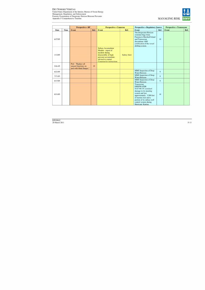
8/7/2019 DNV BOP report - Vol 2 (2)
http://slidepdf.com/reader/full/dnv-bop-report-vol-2-2 178/350
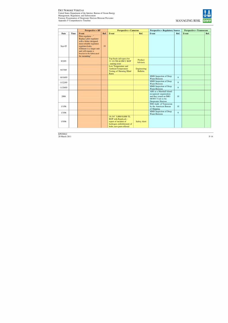
8/7/2019 DNV BOP report - Vol 2 (2)
http://slidepdf.com/reader/full/dnv-bop-report-vol-2-2 179/350
DET NORSKE VERITAS United States Department of the Interior, Bureau of Ocean EnergyManagement, Regulation, and Enforcement
Forensic Examination of Deepwater Horizon Blowout PreventerAppendix F Comprehensive Timeline
EP030842
20 March 2011
Perspective = BP Perspective = Cameron Perspective = Regulatory Sour
Date Time Event Ref. Event Ref. Event Re
Sep-05
Pilot regulator - "Replace pilot regulatorwith a better designed,
more reliable regulator,regulator leaks.(Gilmore is a larger unitand will require abracket to be fabricated
for mounting"
19
9/2/05Top Seals (all types) for21-1/4 5M &10M U BOP
- mating issue
ProductAdvisory
9/27/05
Low Temperature andAmbient TemperatureTesting of Shearing BlindRams
EngineeringBulletin
10/18/05MMS Inspection of DeepWater Horizon
9
11/22/05MMS Inspection of Deep
Water Horizon9
11/29/05MMS Inspection of Deep
Water Horizon9
2006
ABS as a Marshall Island-recognized organizationand they issued an IMOMODU Code to the
Deepwater Horizon
1
1/1/06ISM Audit of Transoceanby the American Bureau
of Shipping
1
1/3/06MMS Inspection of Deep
Water Horizon9
1/5/06
18-3/4" 5,000/10,000 TLBOP with RamLock -report of incident of hydrogen embrittlement of
bolts, new parts offered
Safety Alert

8/7/2019 DNV BOP report - Vol 2 (2)
http://slidepdf.com/reader/full/dnv-bop-report-vol-2-2 180/350
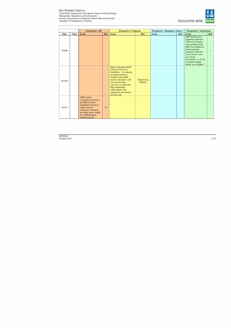
8/7/2019 DNV BOP report - Vol 2 (2)
http://slidepdf.com/reader/full/dnv-bop-report-vol-2-2 181/350
DET NORSKE VERITAS United States Department of the Interior, Bureau of Ocean EnergyManagement, Regulation, and Enforcement
Forensic Examination of Deepwater Horizon Blowout PreventerAppendix F Comprehensive Timeline
EP030842
20 March 2011
Perspective = BP Perspective = Cameron Perspective = Regulatory Sour
Date Time Event Ref. Event Ref. Event Re
7/29/06
8/21/06
High Temperature BOPElastomers GeneralGuidelines - "no industry
accepted method of formally rating BOPpackers and seals", coldseawater provides
convective cooling andhigh temperaturereplacements onlyrequired on ram packers
and top seals
EngineeringBulletin
Jan-07
AMF system -
"Cameron will removethe SEM from the[multiplex] section toreplace the pie-
connectors (customerprovided) and to installthe AMF/deadman
modification kit
19

8/7/2019 DNV BOP report - Vol 2 (2)
http://slidepdf.com/reader/full/dnv-bop-report-vol-2-2 182/350
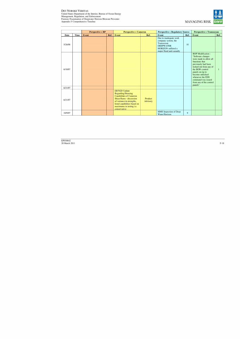
8/7/2019 DNV BOP report - Vol 2 (2)
http://slidepdf.com/reader/full/dnv-bop-report-vol-2-2 183/350

8/7/2019 DNV BOP report - Vol 2 (2)
http://slidepdf.com/reader/full/dnv-bop-report-vol-2-2 184/350
DET NORSKE VERITAS United States Department of the Interior, Bureau of Ocean EnergyManagement, Regulation, and Enforcement
Forensic Examination of Deepwater Horizon Blowout PreventerAppendix F Comprehensive Timeline
EP030842
20 March 2011
Perspective = BP Perspective = Cameron Perspective = Regulatory Sour
Date Time Event Ref. Event Ref. Event Re
10/16/07
Operating Pressure,GeneralRecommendations for
Annular BOPs - minimumclosing pressure 1500psito maximum 3000psi, "notsubject to wellborepressure assist"
Engineering
Bulletin
11/9/07MMS Inspection of Deep
Water Horizon9
11/13/07
Cameron Ram BOPHydro-Mechanical
Locking Systems GeneralInformation - commentson ST locks
EngineeringBulletin
Jan-08BP audit of the drillingoperations on DWH
1
1/11/08MMS Inspection of DeepWater Horizon
9
1/21/08
Shearing Capabilities of Cameron Rams - provides
equations and tabledconstants for variousmodels and pipe sizes
EngineeringBulletin
1/24/08
Design improvement to18-3/4" 15M TL BOP
Operating Piston Buttons -done to increase fatiguelife
EngineeringBulletin
2/8/08 MMS Inspection of DeepWater Horizon
9
3/12/08MMS Inspection of DeepWater Horizon
9

8/7/2019 DNV BOP report - Vol 2 (2)
http://slidepdf.com/reader/full/dnv-bop-report-vol-2-2 185/350
DET NORSKE VERITAS United States Department of the Interior, Bureau of Ocean EnergyManagement, Regulation, and Enforcement
Forensic Examination of Deepwater Horizon Blowout PreventerAppendix F Comprehensive Timeline
EP030842
20 March 2011
Perspective = BP Perspective = Cameron Perspective = Regulatory Sour
Date Time Event Ref. Event Ref. Event Re
4/2/08
Modular Control PodMark I Stack& RiserMultiport Stinger Segment
Inspection - reports of cracking in stingerassemblies, attributed to"environmentalembrittlement"
Product
Advisory
8/15/08MMS Inspection of Deep
Water Horizon9
Sep-08
Replacement of flexjoint. Used flex joint
from TransoceanDeepwater Nautiluswith a 37.5 in. 'G' x 'H'crossover
19
Sep-08
10/21/08
10/28/08MMS Inspection of Deep
Water Horizon9
11/18/08MMS Inspection of DeepWater Horizon
9
2/12/09
Mark III Modular Drilling
Control Pod SEMIndication Faults - reportsof 2 indication faults,inspection recommended
Safety Alert
2/24/09
ST Locks - manufacturingprocess issue identified in
TL BOP, inspectionrecommended
ProductAdvisory
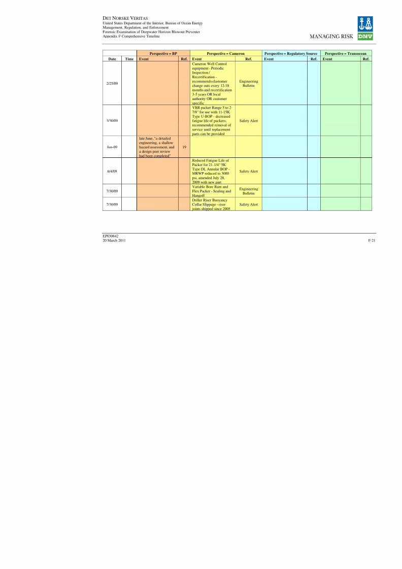
8/7/2019 DNV BOP report - Vol 2 (2)
http://slidepdf.com/reader/full/dnv-bop-report-vol-2-2 186/350
DET NORSKE VERITAS United States Department of the Interior, Bureau of Ocean EnergyManagement, Regulation, and Enforcement
Forensic Examination of Deepwater Horizon Blowout PreventerAppendix F Comprehensive Timeline
EP030842
20 March 2011
Perspective = BP Perspective = Cameron Perspective = Regulatory Sour
Date Time Event Ref. Event Ref. Event Re
2/25/09
Cameron Well Controlequipment - PeriodicInspection /
Recertification -recommends elastomerchange outs every 12-18months and recertification3-5 years OR local
authority OR customerspecific
EngineeringBulletin
3/30/09
VBR packer Range 5 to 2-
7/8" for use with 11-15KType U-BOP - decreasedfatigue life of packers,recommended removal of
service until replacementparts can be provided
Safety Alert
Jun-09
late June, "a detailedengineering, a shallowhazard assessment, anda design peer review
had been completed"
19
6/4/09
Reduced Fatigue Life of Packer for 21-1/4" 5KType DL Annular BOP -MRWP reduced to 3000
psi, amended July 28,2009 with new part
Safety Alert
7/30/09
Variable Bore Ram and
Flex Packer - Sealing andHangoff
Engineering
Bulletin
7/30/09Driller Riser BuoyancyCollar Slippage - riserjoints shipped since 2005
Safety Alert

8/7/2019 DNV BOP report - Vol 2 (2)
http://slidepdf.com/reader/full/dnv-bop-report-vol-2-2 187/350
DET NORSKE VERITAS United States Department of the Interior, Bureau of Ocean EnergyManagement, Regulation, and Enforcement
Forensic Examination of Deepwater Horizon Blowout PreventerAppendix F Comprehensive Timeline
EP030842
20 March 2011
Perspective = BP Perspective = Cameron Perspective = Regulatory Sour
Date Time Event Ref. Event Ref. Event Re
8/3/09
8/31/09
Sep-09Deepwater Horizonfollow-up rig audit
19out-of-service periodoccurred between wells
1
Sep-09
BP rig and maritimeassurance audit (follow upto Jan 2008 audit) - audit
indicated the spare podwere not operable
10
9/23/09
9/28/09MMS Inspection of DeepWater Horizon
9
10/6/09
"initial drilling of the
Macondo well beganwith Transocean's semi-submersible Marianasand continued until
November 8, 2009."
19
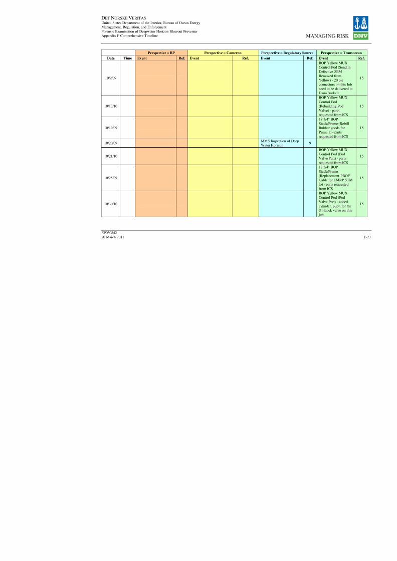
8/7/2019 DNV BOP report - Vol 2 (2)
http://slidepdf.com/reader/full/dnv-bop-report-vol-2-2 188/350
DET NORSKE VERITAS United States Department of the Interior, Bureau of Ocean EnergyManagement, Regulation, and Enforcement
Forensic Examination of Deepwater Horizon Blowout PreventerAppendix F Comprehensive Timeline
EP030842
20 March 2011
Perspective = BP Perspective = Cameron Perspective = Regulatory Sour
Date Time Event Ref. Event Ref. Event Re
10/9/09
10/13/10
10/19/09
10/20/09MMS Inspection of DeepWater Horizon
9
10/21/10
10/25/09
10/30/10

8/7/2019 DNV BOP report - Vol 2 (2)
http://slidepdf.com/reader/full/dnv-bop-report-vol-2-2 189/350
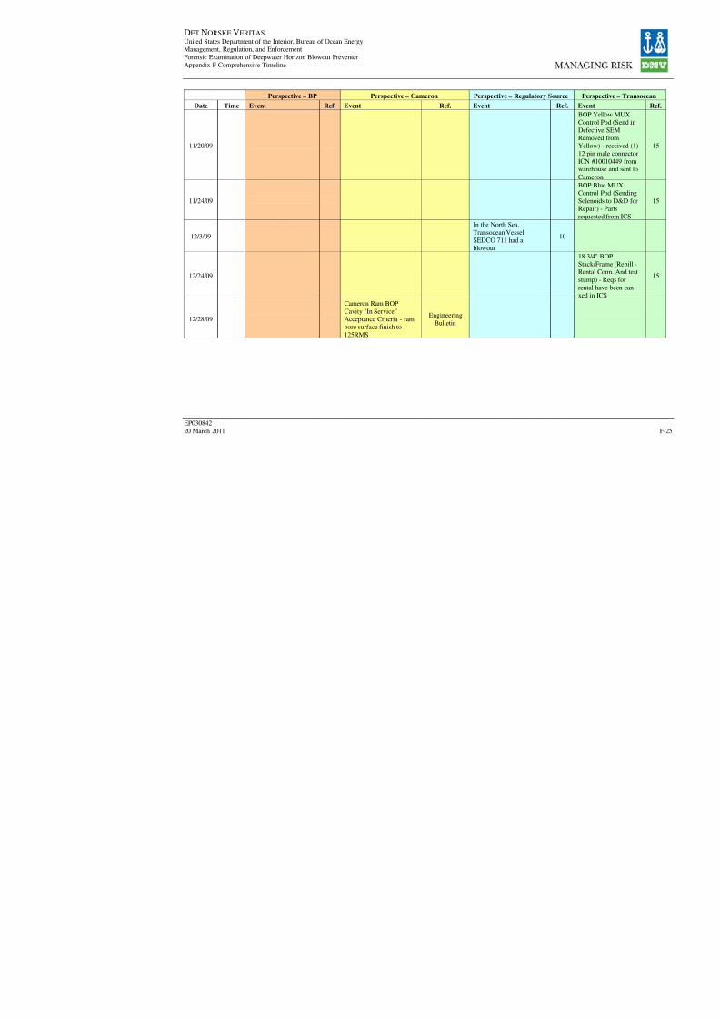
8/7/2019 DNV BOP report - Vol 2 (2)
http://slidepdf.com/reader/full/dnv-bop-report-vol-2-2 190/350
DET NORSKE VERITAS United States Department of the Interior, Bureau of Ocean EnergyManagement, Regulation, and Enforcement
Forensic Examination of Deepwater Horizon Blowout PreventerAppendix F Comprehensive Timeline
EP030842
20 March 2011
Perspective = BP Perspective = Cameron Perspective = Regulatory Sour
Date Time Event Ref. Event Ref. Event Re
11/20/09
11/24/09
12/3/09
In the North Sea,Transocean VesselSEDCO 711 had a
blowout
1
12/24/09
12/28/09
Cameron Ram BOPCavity "In Service"Acceptance Criteria - rambore surface finish to
125RMS
Engineering
Bulletin

8/7/2019 DNV BOP report - Vol 2 (2)
http://slidepdf.com/reader/full/dnv-bop-report-vol-2-2 191/350
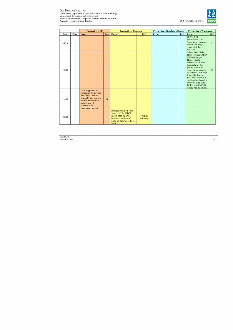
8/7/2019 DNV BOP report - Vol 2 (2)
http://slidepdf.com/reader/full/dnv-bop-report-vol-2-2 192/350
DET NORSKE VERITAS United States Department of the Interior, Bureau of Ocean EnergyManagement, Regulation, and Enforcement
Forensic Examination of Deepwater Horizon Blowout PreventerAppendix F Comprehensive Timeline
EP030842
20 March 2011
Perspective = BP Perspective = Cameron Perspective = Regulatory Sour
Date Time Event Ref. Event Ref. Event Re
1/9/10
1/10/10
1/14/10
"MMS approved anapplication for RevisedNew Well…and theMacondo well plan was
updated to reflect thereplacement of Marianas withDeepwater Horizon."
19
1/20/10
Bonnet Bolts and BonnetStuds, 13-15M U-BOPand 18-15M TL BOP -
issue with one heat of parts, not believed to be inservice
Product
Advisory

8/7/2019 DNV BOP report - Vol 2 (2)
http://slidepdf.com/reader/full/dnv-bop-report-vol-2-2 193/350
DET NORSKE VERITAS United States Department of the Interior, Bureau of Ocean EnergyManagement, Regulation, and Enforcement
Forensic Examination of Deepwater Horizon Blowout PreventerAppendix F Comprehensive Timeline
EP030842
20 March 2011
Perspective = BP Perspective = Cameron Perspective = Regulatory Sour
Date Time Event Ref. Event Ref. Event Re
1/21/10
1/27/10
1/31/10"Deepwater Horizon
arrived on site."19
1/31/10
1/31/10
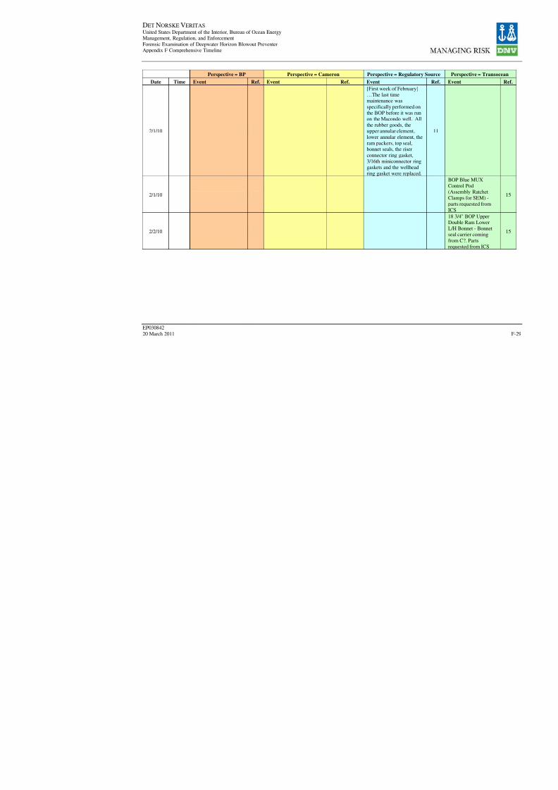
8/7/2019 DNV BOP report - Vol 2 (2)
http://slidepdf.com/reader/full/dnv-bop-report-vol-2-2 194/350
DET NORSKE VERITAS United States Department of the Interior, Bureau of Ocean EnergyManagement, Regulation, and Enforcement
Forensic Examination of Deepwater Horizon Blowout PreventerAppendix F Comprehensive Timeline
EP030842
20 March 2011
Perspective = BP Perspective = Cameron Perspective = Regulatory Sour
Date Time Event Ref. Event Ref. Event Re
2/1/10
[First week of February]…The last timemaintenance was
specifically performed onthe BOP before it was runon the Macondo well. Allthe rubber goods, theupper annular element,
lower annular element, theram packers, top seal,bonnet seals, the riser
connector ring gasket,3/16th miniconnector ringgaskets and the wellhead
ring gasket were replaced.
1
2/1/10
2/2/10
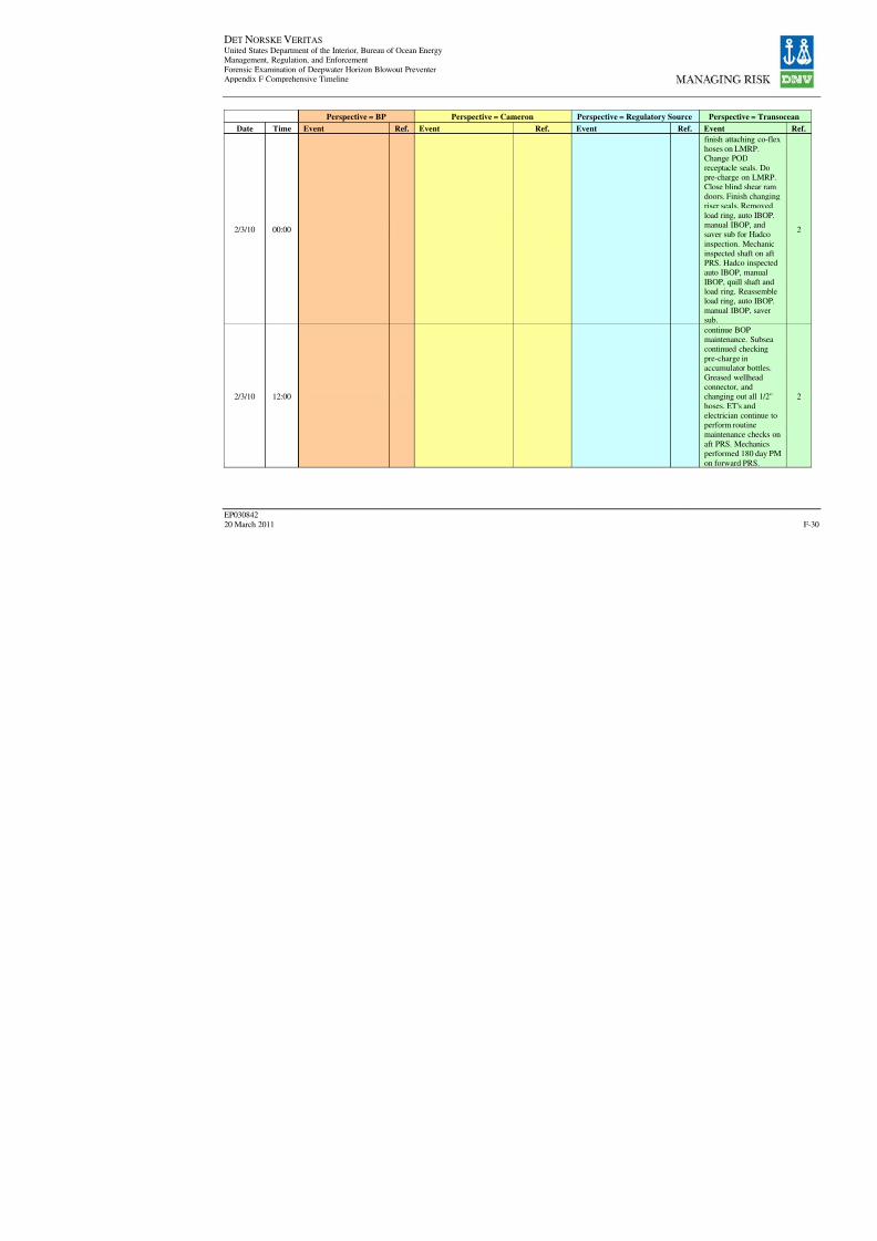
8/7/2019 DNV BOP report - Vol 2 (2)
http://slidepdf.com/reader/full/dnv-bop-report-vol-2-2 195/350
DET NORSKE VERITAS United States Department of the Interior, Bureau of Ocean EnergyManagement, Regulation, and Enforcement
Forensic Examination of Deepwater Horizon Blowout PreventerAppendix F Comprehensive Timeline
EP030842
20 March 2011
Perspective = BP Perspective = Cameron Perspective = Regulatory Sour
Date Time Event Ref. Event Ref. Event Re
2/3/10 00:00
2/3/10 12:00
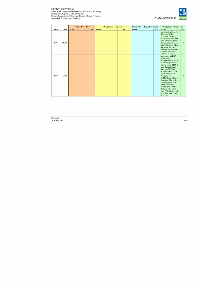
8/7/2019 DNV BOP report - Vol 2 (2)
http://slidepdf.com/reader/full/dnv-bop-report-vol-2-2 196/350
DET NORSKE VERITAS United States Department of the Interior, Bureau of Ocean EnergyManagement, Regulation, and Enforcement
Forensic Examination of Deepwater Horizon Blowout PreventerAppendix F Comprehensive Timeline
EP030842
20 March 2011
Perspective = BP Perspective = Cameron Perspective = Regulatory Sour
Date Time Event Ref. Event Ref. Event Re
2/4/10 00:00
2/4/10 12:00

8/7/2019 DNV BOP report - Vol 2 (2)
http://slidepdf.com/reader/full/dnv-bop-report-vol-2-2 197/350
DET NORSKE VERITAS United States Department of the Interior, Bureau of Ocean EnergyManagement, Regulation, and Enforcement
Forensic Examination of Deepwater Horizon Blowout PreventerAppendix F Comprehensive Timeline
EP030842
20 March 2011
Perspective = BP Perspective = Cameron Perspective = Regulatory Sour
Date Time Event Ref. Event Ref. Event Re
2/5/10 00:00
2/5/10 12:00
2/5/10
2/5/10
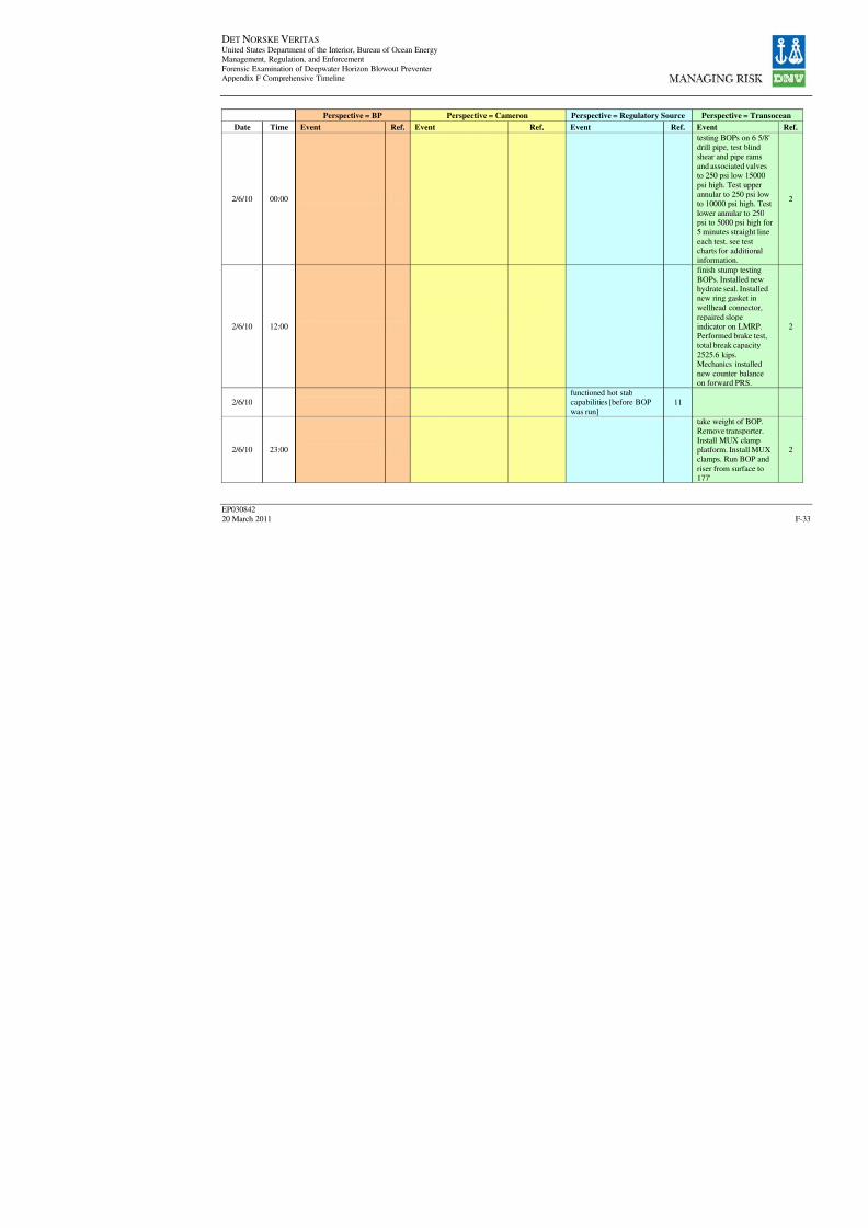
8/7/2019 DNV BOP report - Vol 2 (2)
http://slidepdf.com/reader/full/dnv-bop-report-vol-2-2 198/350

8/7/2019 DNV BOP report - Vol 2 (2)
http://slidepdf.com/reader/full/dnv-bop-report-vol-2-2 199/350
DET NORSKE VERITAS United States Department of the Interior, Bureau of Ocean EnergyManagement, Regulation, and Enforcement
Forensic Examination of Deepwater Horizon Blowout PreventerAppendix F Comprehensive Timeline
EP030842
20 March 2011
Perspective = BP Perspective = Cameron Perspective = Regulatory Sour
Date Time Event Ref. Event Ref. Event Re
2/6/10 "drilling activitiesrecommenced"
19
2/6/10
2/8/10 05:30
2/8/10 08:00
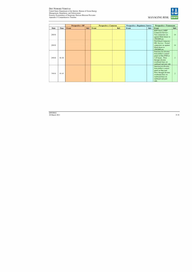
8/7/2019 DNV BOP report - Vol 2 (2)
http://slidepdf.com/reader/full/dnv-bop-report-vol-2-2 200/350
DET NORSKE VERITAS United States Department of the Interior, Bureau of Ocean EnergyManagement, Regulation, and Enforcement
Forensic Examination of Deepwater Horizon Blowout PreventerAppendix F Comprehensive Timeline
EP030842
20 March 2011
Perspective = BP Perspective = Cameron Perspective = Regulatory Sour
Date Time Event Ref. Event Ref. Event Re
2/8/10
2/8/10
2/9/10 01:30
2/9/10 01:45

8/7/2019 DNV BOP report - Vol 2 (2)
http://slidepdf.com/reader/full/dnv-bop-report-vol-2-2 201/350
DET NORSKE VERITAS United States Department of the Interior, Bureau of Ocean EnergyManagement, Regulation, and Enforcement
Forensic Examination of Deepwater Horizon Blowout PreventerAppendix F Comprehensive Timeline
EP030842
20 March 2011
Perspective = BP Perspective = Cameron Perspective = Regulatory Sour
Date Time Event Ref. Event Ref. Event Re
2/9/10 05:00
2/9/10 05:00
2/9/10 05:30
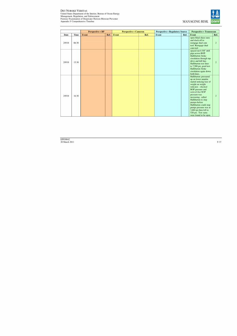
8/7/2019 DNV BOP report - Vol 2 (2)
http://slidepdf.com/reader/full/dnv-bop-report-vol-2-2 202/350
DET NORSKE VERITAS United States Department of the Interior, Bureau of Ocean EnergyManagement, Regulation, and Enforcement
Forensic Examination of Deepwater Horizon Blowout PreventerAppendix F Comprehensive Timeline
EP030842
20 March 2011
Perspective = BP Perspective = Cameron Perspective = Regulatory Sour
Date Time Event Ref. Event Ref. Event Re
2/9/10 06:30
2/9/10 15:30
2/9/10 16:30

8/7/2019 DNV BOP report - Vol 2 (2)
http://slidepdf.com/reader/full/dnv-bop-report-vol-2-2 203/350
DET NORSKE VERITAS United States Department of the Interior, Bureau of Ocean EnergyManagement, Regulation, and Enforcement
Forensic Examination of Deepwater Horizon Blowout PreventerAppendix F Comprehensive Timeline
EP030842
20 March 2011
Perspective = BP Perspective = Cameron Perspective = Regulatory Sour
Date Time Event Ref. Event Ref. Event Re
2/9/10 16:30
2/9/10
Cameron DR 30 3"Hydraulic Drilling ChokeOperations with Cameron
Choke Control Console -
provided recommendedoperational instructions,update April 14, 2010
with modifications
Safety Alert

8/7/2019 DNV BOP report - Vol 2 (2)
http://slidepdf.com/reader/full/dnv-bop-report-vol-2-2 204/350
DET NORSKE VERITAS United States Department of the Interior, Bureau of Ocean EnergyManagement, Regulation, and Enforcement
Forensic Examination of Deepwater Horizon Blowout PreventerAppendix F Comprehensive Timeline
EP030842
20 March 2011
Perspective = BP Perspective = Cameron Perspective = Regulatory Sour
Date Time Event Ref. Event Ref. Event Re
2/9/10
2/10/10 00:00
2/10/10 02:30

8/7/2019 DNV BOP report - Vol 2 (2)
http://slidepdf.com/reader/full/dnv-bop-report-vol-2-2 205/350
DET NORSKE VERITAS United States Department of the Interior, Bureau of Ocean EnergyManagement, Regulation, and Enforcement
Forensic Examination of Deepwater Horizon Blowout PreventerAppendix F Comprehensive Timeline
EP030842
20 March 2011
Perspective = BP Perspective = Cameron Perspective = Regulatory Sour
Date Time Event Ref. Event Ref. Event Re
2/10/10 02:30
2/10/10 08:00
2/10/10 13:00
2/10/10
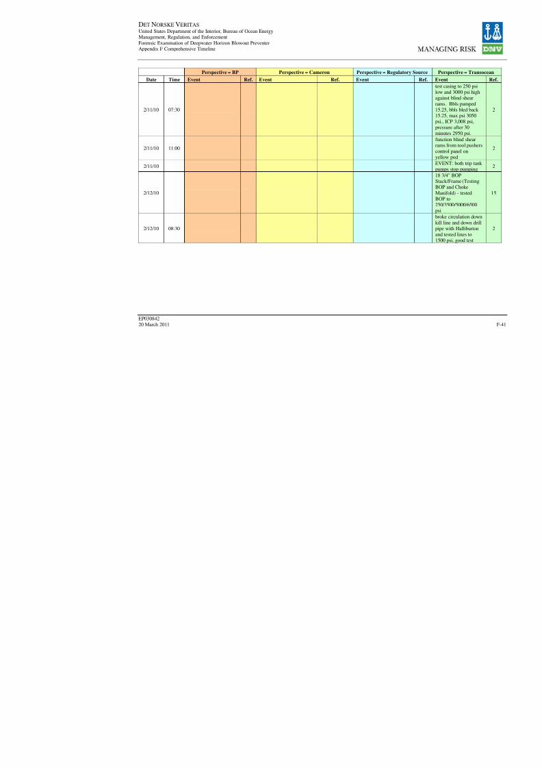
8/7/2019 DNV BOP report - Vol 2 (2)
http://slidepdf.com/reader/full/dnv-bop-report-vol-2-2 206/350
DET NORSKE VERITAS United States Department of the Interior, Bureau of Ocean EnergyManagement, Regulation, and Enforcement
Forensic Examination of Deepwater Horizon Blowout PreventerAppendix F Comprehensive Timeline
EP030842
20 March 2011
Perspective = BP Perspective = Cameron Perspective = Regulatory Sour
Date Time Event Ref. Event Ref. Event Re
2/11/10 07:30
2/11/10 11:00
2/11/10
2/12/10
2/12/10 08:30

8/7/2019 DNV BOP report - Vol 2 (2)
http://slidepdf.com/reader/full/dnv-bop-report-vol-2-2 207/350

8/7/2019 DNV BOP report - Vol 2 (2)
http://slidepdf.com/reader/full/dnv-bop-report-vol-2-2 208/350
DET NORSKE VERITAS United States Department of the Interior, Bureau of Ocean EnergyManagement, Regulation, and Enforcement
Forensic Examination of Deepwater Horizon Blowout PreventerAppendix F Comprehensive Timeline
EP030842
20 March 2011
Perspective = BP Perspective = Cameron Perspective = Regulatory Sour
Date Time Event Ref. Event Ref. Event Re
2/12/10 13:00
2/12/10 18:30
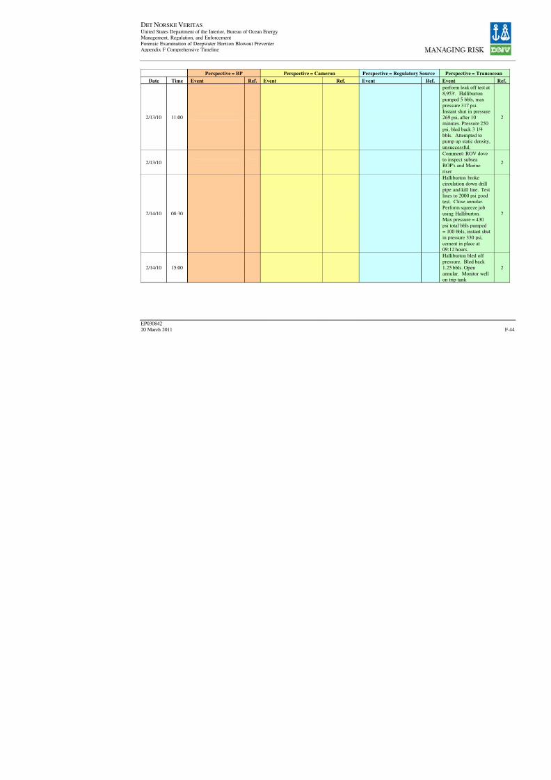
8/7/2019 DNV BOP report - Vol 2 (2)
http://slidepdf.com/reader/full/dnv-bop-report-vol-2-2 209/350
DET NORSKE VERITAS United States Department of the Interior, Bureau of Ocean EnergyManagement, Regulation, and Enforcement
Forensic Examination of Deepwater Horizon Blowout PreventerAppendix F Comprehensive Timeline
EP030842
20 March 2011
Perspective = BP Perspective = Cameron Perspective = Regulatory Sour
Date Time Event Ref. Event Ref. Event Re
2/13/10 11:00
2/13/10
2/14/10 08:30
2/14/10 15:00

8/7/2019 DNV BOP report - Vol 2 (2)
http://slidepdf.com/reader/full/dnv-bop-report-vol-2-2 210/350
DET NORSKE VERITAS United States Department of the Interior, Bureau of Ocean EnergyManagement, Regulation, and Enforcement
Forensic Examination of Deepwater Horizon Blowout PreventerAppendix F Comprehensive Timeline
EP030842
20 March 2011
Perspective = BP Perspective = Cameron Perspective = Regulatory Sour
Date Time Event Ref. Event Ref. Event Re
2/14/10 21:14
2/14/10
2/15/10
2/16/10
2/16/10
2/17/10 00:00

8/7/2019 DNV BOP report - Vol 2 (2)
http://slidepdf.com/reader/full/dnv-bop-report-vol-2-2 211/350
DET NORSKE VERITAS United States Department of the Interior, Bureau of Ocean EnergyManagement, Regulation, and Enforcement
Forensic Examination of Deepwater Horizon Blowout PreventerAppendix F Comprehensive Timeline
EP030842
20 March 2011
Perspective = BP Perspective = Cameron Perspective = Regulatory Sour
Date Time Event Ref. Event Ref. Event Re
2/17/10 02:30
2/17/10 04:30
2/17/10 20:30
2/17/10 20:30
2/17/10 23:30
2/17/10MMS Inspection of Deep
Water Horizon9
2/17/10

8/7/2019 DNV BOP report - Vol 2 (2)
http://slidepdf.com/reader/full/dnv-bop-report-vol-2-2 212/350
DET NORSKE VERITAS United States Department of the Interior, Bureau of Ocean EnergyManagement, Regulation, and Enforcement
Forensic Examination of Deepwater Horizon Blowout PreventerAppendix F Comprehensive Timeline
EP030842
20 March 2011
Perspective = BP Perspective = Cameron Perspective = Regulatory Sour
Date Time Event Ref. Event Ref. Event Re
2/18/10 15:30
2/18/10 17:30
2/18/10 18:00
2/18/10
2/19/10 20:30
2/20/10 07:00
2/20/10
2/23/10 02:00
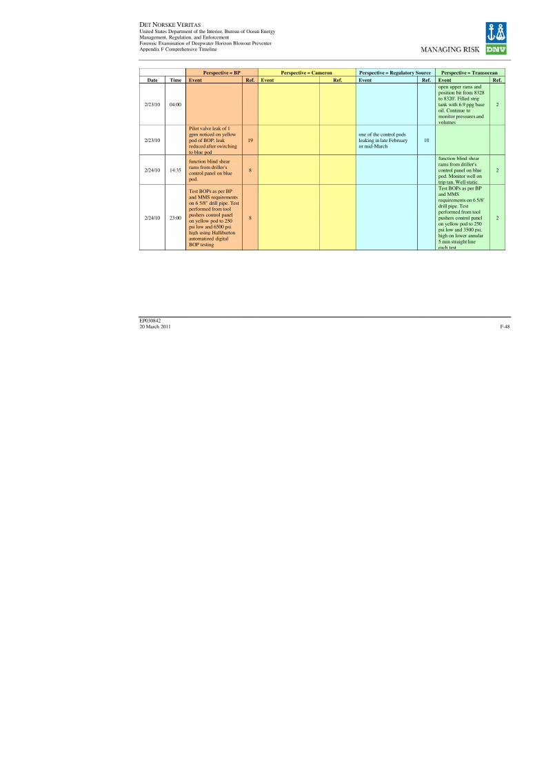
8/7/2019 DNV BOP report - Vol 2 (2)
http://slidepdf.com/reader/full/dnv-bop-report-vol-2-2 213/350

8/7/2019 DNV BOP report - Vol 2 (2)
http://slidepdf.com/reader/full/dnv-bop-report-vol-2-2 214/350
DET NORSKE VERITAS United States Department of the Interior, Bureau of Ocean EnergyManagement, Regulation, and Enforcement
Forensic Examination of Deepwater Horizon Blowout PreventerAppendix F Comprehensive Timeline
EP030842
20 March 2011
Perspective = BP Perspective = Cameron Perspective = Regulatory Sour
Date Time Event Ref. Event Ref. Event Re
2/24/10
Remarks: Pilot leak onBOP's yellow pod at 1GPM switched to blue
pod and leak slowed -put valve function inblock - checked outokay - will put BOPstack functions in block
when drill pipe is abovestack to confirm leak ison stack
8

8/7/2019 DNV BOP report - Vol 2 (2)
http://slidepdf.com/reader/full/dnv-bop-report-vol-2-2 215/350
DET NORSKE VERITAS United States Department of the Interior, Bureau of Ocean EnergyManagement, Regulation, and Enforcement
Forensic Examination of Deepwater Horizon Blowout PreventerAppendix F Comprehensive Timeline
EP030842
20 March 2011
Perspective = BP Perspective = Cameron Perspective = Regulatory Sour
Date Time Event Ref. Event Ref. Event Re
2/25/10
Update: Continue to testsub-sea BOPs as perMMS and BP
requirements on 6 5/8"drill pipe. Testperformed on yellowpod from TPTP. Testlower annular and
associated valves to 250psi low and 3500 psihigh for 5 minutes each
test. Test upper annular,kelly hose andassociated valves to 250
psi low for 5 minutes
straight line and 5000psi high until greenlight registered on
Halliburton automatizeddigital BOP testingsystem. Test all piperams and fail safe
valves to 250 psi lowfor 5 minutes straightline and 6500 psi highuntil green light
registered onHalliburton automatizeddigital BOP testingsystem. (note BOP
testing performed at6,726' MD)
8
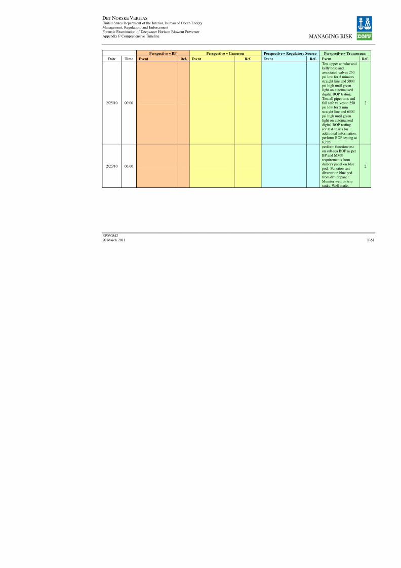
8/7/2019 DNV BOP report - Vol 2 (2)
http://slidepdf.com/reader/full/dnv-bop-report-vol-2-2 216/350
DET NORSKE VERITAS United States Department of the Interior, Bureau of Ocean EnergyManagement, Regulation, and Enforcement
Forensic Examination of Deepwater Horizon Blowout PreventerAppendix F Comprehensive Timeline
EP030842
20 March 2011
Perspective = BP Perspective = Cameron Perspective = Regulatory Sour
Date Time Event Ref. Event Ref. Event Re
2/25/10 00:00
2/25/10 06:00

8/7/2019 DNV BOP report - Vol 2 (2)
http://slidepdf.com/reader/full/dnv-bop-report-vol-2-2 217/350
DET NORSKE VERITAS United States Department of the Interior, Bureau of Ocean EnergyManagement, Regulation, and Enforcement
Forensic Examination of Deepwater Horizon Blowout PreventerAppendix F Comprehensive Timeline
EP030842
20 March 2011
Perspective = BP Perspective = Cameron Perspective = Regulatory Sour
Date Time Event Ref. Event Ref. Event Re
2/25/10
2/25/10
2/26/10

8/7/2019 DNV BOP report - Vol 2 (2)
http://slidepdf.com/reader/full/dnv-bop-report-vol-2-2 218/350
DET NORSKE VERITAS United States Department of the Interior, Bureau of Ocean EnergyManagement, Regulation, and Enforcement
Forensic Examination of Deepwater Horizon Blowout PreventerAppendix F Comprehensive Timeline
EP030842
20 March 2011
Perspective = BP Perspective = Cameron Perspective = Regulatory Sour
Date Time Event Ref. Event Ref. Event Re
2/28/10
3/1/10Mr. Rodriguez (BP)inspection of DWH
1
3/1/10
Patrick Morgan had beenset up to drill and had
pulled drill string 15 to 20feet through the BOP.200,000 pounds of hook load pressure spiked as
that drill pipe was pulledup through that annular.
1
3/1/10
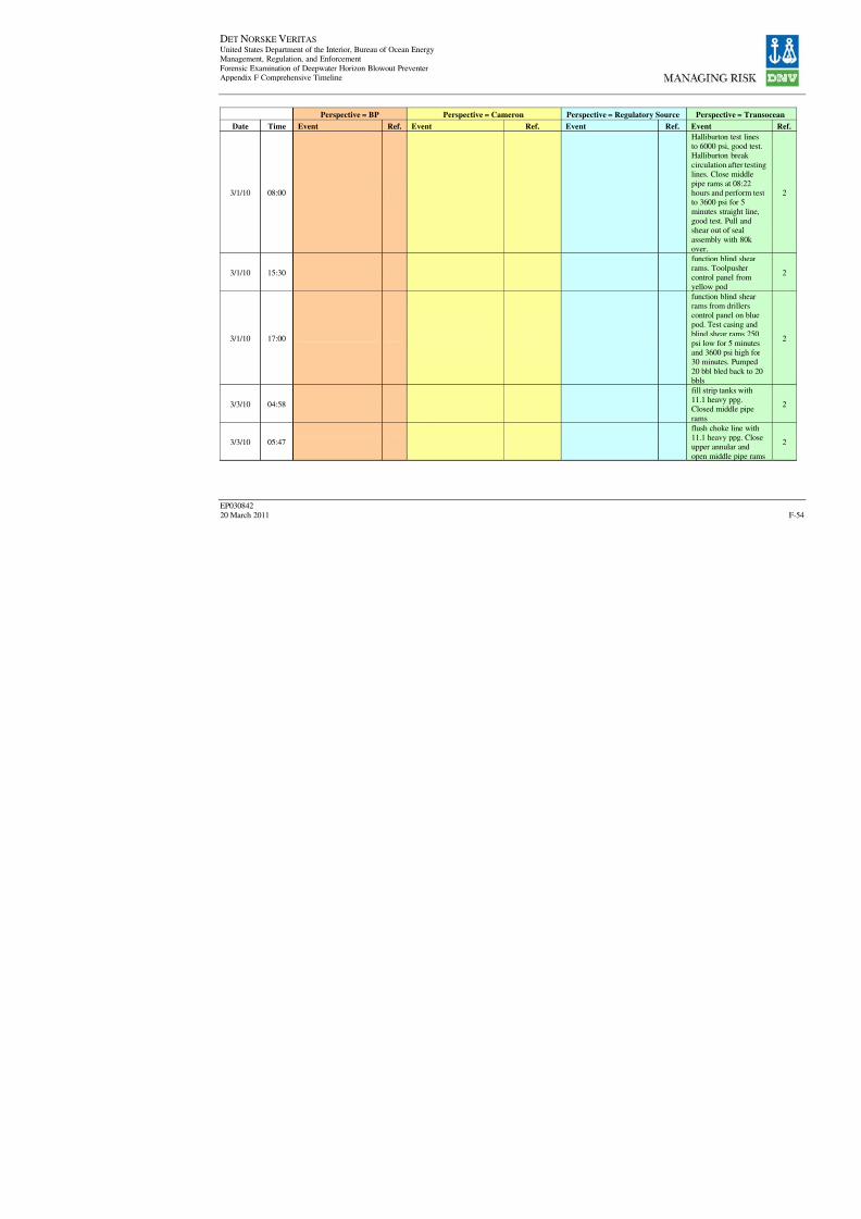
8/7/2019 DNV BOP report - Vol 2 (2)
http://slidepdf.com/reader/full/dnv-bop-report-vol-2-2 219/350

8/7/2019 DNV BOP report - Vol 2 (2)
http://slidepdf.com/reader/full/dnv-bop-report-vol-2-2 220/350

8/7/2019 DNV BOP report - Vol 2 (2)
http://slidepdf.com/reader/full/dnv-bop-report-vol-2-2 221/350
DET NORSKE VERITAS United States Department of the Interior, Bureau of Ocean EnergyManagement, Regulation, and Enforcement
Forensic Examination of Deepwater Horizon Blowout PreventerAppendix F Comprehensive Timeline
EP030842
20 March 2011
Perspective = BP Perspective = Cameron Perspective = Regulatory Sour
Date Time Event Ref. Event Ref. Event Re
3/7/10
3/8/10 01:00
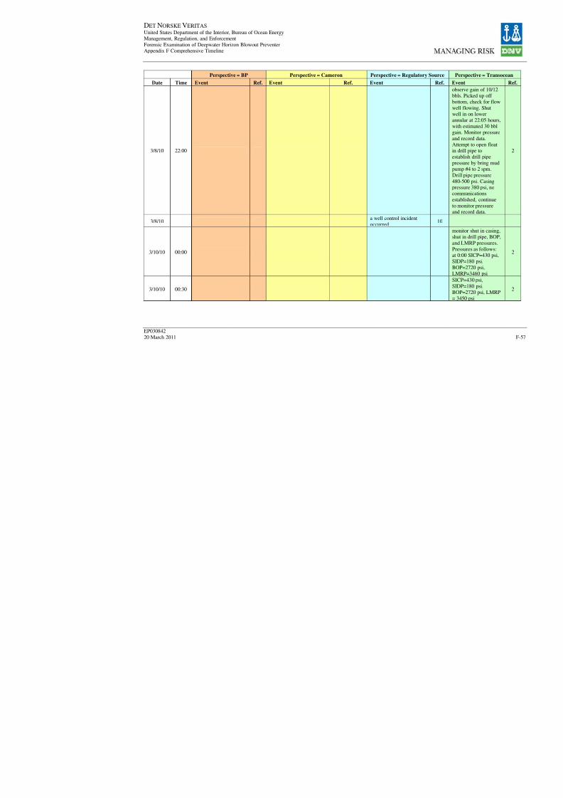
8/7/2019 DNV BOP report - Vol 2 (2)
http://slidepdf.com/reader/full/dnv-bop-report-vol-2-2 222/350
DET NORSKE VERITAS United States Department of the Interior, Bureau of Ocean EnergyManagement, Regulation, and Enforcement
Forensic Examination of Deepwater Horizon Blowout PreventerAppendix F Comprehensive Timeline
EP030842
20 March 2011
Perspective = BP Perspective = Cameron Perspective = Regulatory Sour
Date Time Event Ref. Event Ref. Event Re
3/8/10 22:00
3/8/10a well control incidentoccurred
1
3/10/10 00:00
3/10/10 00:30

8/7/2019 DNV BOP report - Vol 2 (2)
http://slidepdf.com/reader/full/dnv-bop-report-vol-2-2 223/350
DET NORSKE VERITAS United States Department of the Interior, Bureau of Ocean EnergyManagement, Regulation, and Enforcement
Forensic Examination of Deepwater Horizon Blowout PreventerAppendix F Comprehensive Timeline
EP030842
20 March 2011
Perspective = BP Perspective = Cameron Perspective = Regulatory Sour
Date Time Event Ref. Event Ref. Event Re
3/10/10 01:00
3/10/10 01:30
3/10/10 02:00
3/10/10 02:30
3/10/10 03:00
3/10/10 03:30
3/10/10 04:00
3/10/10 04:30
3/10/10 05:00
3/10/10 05:30

8/7/2019 DNV BOP report - Vol 2 (2)
http://slidepdf.com/reader/full/dnv-bop-report-vol-2-2 224/350
DET NORSKE VERITAS United States Department of the Interior, Bureau of Ocean EnergyManagement, Regulation, and Enforcement
Forensic Examination of Deepwater Horizon Blowout PreventerAppendix F Comprehensive Timeline
EP030842
20 March 2011
Perspective = BP Perspective = Cameron Perspective = Regulatory Sour
Date Time Event Ref. Event Ref. Event Re
3/10/10 06:00
3/10/10 06:30
3/10/10 07:00
3/10/10 07:30
3/10/10 08:00
3/10/10 08:30
3/10/10 09:00
3/10/10 09:30
3/10/10 10:00
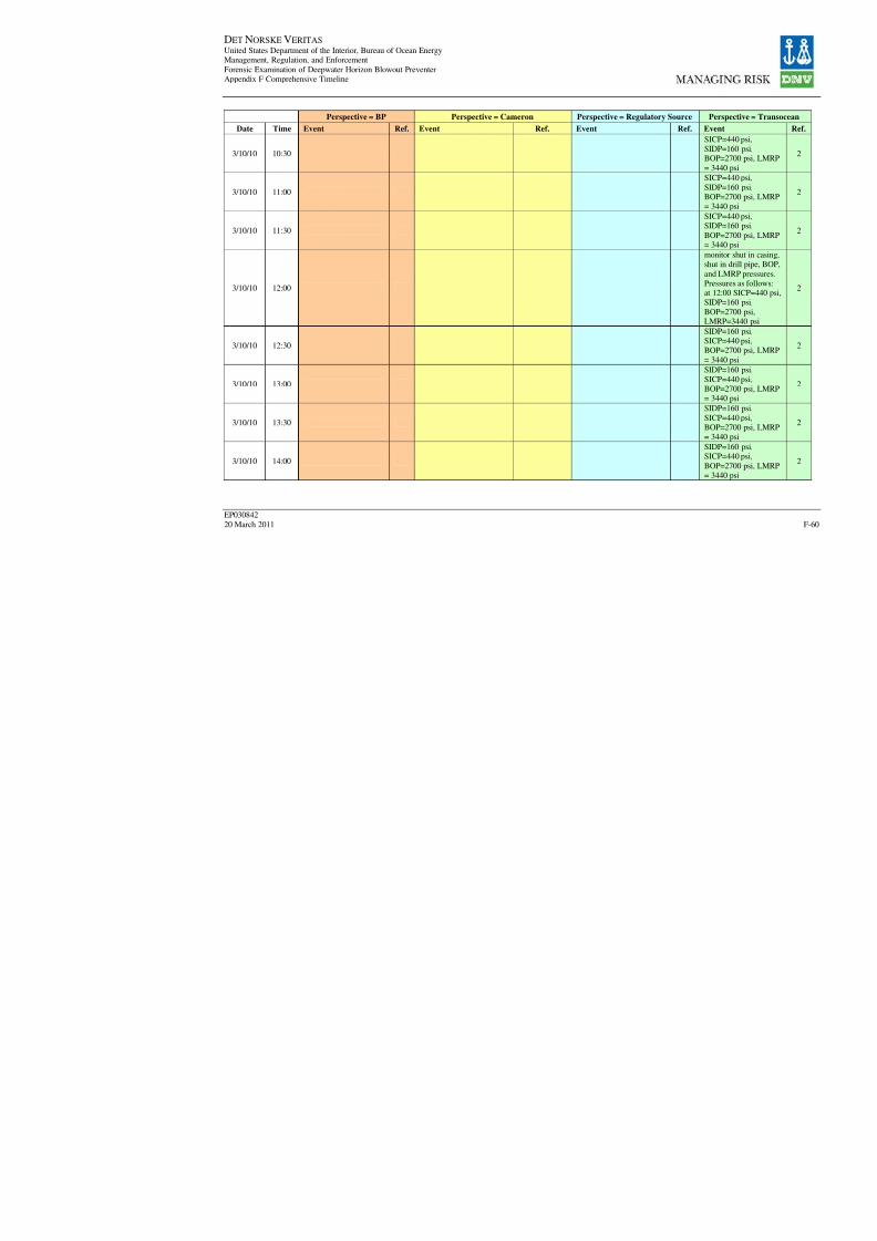
8/7/2019 DNV BOP report - Vol 2 (2)
http://slidepdf.com/reader/full/dnv-bop-report-vol-2-2 225/350
DET NORSKE VERITAS United States Department of the Interior, Bureau of Ocean EnergyManagement, Regulation, and Enforcement
Forensic Examination of Deepwater Horizon Blowout PreventerAppendix F Comprehensive Timeline
EP030842
20 March 2011
Perspective = BP Perspective = Cameron Perspective = Regulatory Sour
Date Time Event Ref. Event Ref. Event Re
3/10/10 10:30
3/10/10 11:00
3/10/10 11:30
3/10/10 12:00
3/10/10 12:30
3/10/10 13:00
3/10/10 13:30
3/10/10 14:00
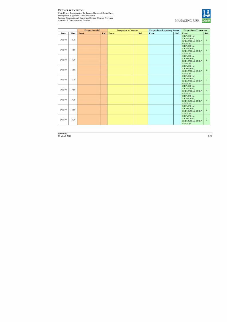
8/7/2019 DNV BOP report - Vol 2 (2)
http://slidepdf.com/reader/full/dnv-bop-report-vol-2-2 226/350
DET NORSKE VERITAS United States Department of the Interior, Bureau of Ocean EnergyManagement, Regulation, and Enforcement
Forensic Examination of Deepwater Horizon Blowout PreventerAppendix F Comprehensive Timeline
EP030842
20 March 2011
Perspective = BP Perspective = Cameron Perspective = Regulatory Sour
Date Time Event Ref. Event Ref. Event Re
3/10/10 14:30
3/10/10 15:00
3/10/10 15:30
3/10/10 16:00
3/10/10 16:30
3/10/10 17:00
3/10/10 17:30
3/10/10 18:00
3/10/10 18:30

8/7/2019 DNV BOP report - Vol 2 (2)
http://slidepdf.com/reader/full/dnv-bop-report-vol-2-2 227/350
DET NORSKE VERITAS United States Department of the Interior, Bureau of Ocean EnergyManagement, Regulation, and Enforcement
Forensic Examination of Deepwater Horizon Blowout PreventerAppendix F Comprehensive Timeline
EP030842
20 March 2011
Perspective = BP Perspective = Cameron Perspective = Regulatory Sour
Date Time Event Ref. Event Ref. Event Re
3/10/10 19:00
3/10/10 19:30
3/10/10 20:00
3/10/10 20:30
3/10/10 21:00
3/10/10 21:30
3/10/10 22:00
3/10/10 22:30
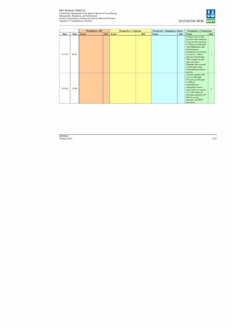
8/7/2019 DNV BOP report - Vol 2 (2)
http://slidepdf.com/reader/full/dnv-bop-report-vol-2-2 228/350
DET NORSKE VERITAS United States Department of the Interior, Bureau of Ocean EnergyManagement, Regulation, and Enforcement
Forensic Examination of Deepwater Horizon Blowout PreventerAppendix F Comprehensive Timeline
EP030842
20 March 2011
Perspective = BP Perspective = Cameron Perspective = Regulatory Sour
Date Time Event Ref. Event Ref. Event Re
3/11/10 09:30
3/11/10 12:00
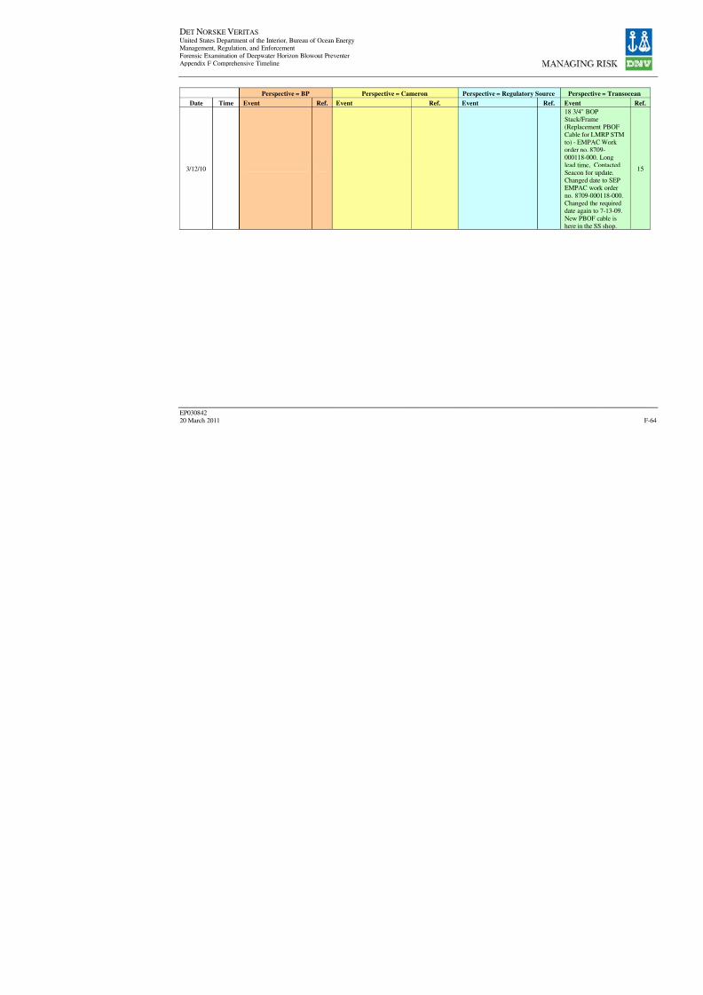
8/7/2019 DNV BOP report - Vol 2 (2)
http://slidepdf.com/reader/full/dnv-bop-report-vol-2-2 229/350
DET NORSKE VERITAS United States Department of the Interior, Bureau of Ocean EnergyManagement, Regulation, and Enforcement
Forensic Examination of Deepwater Horizon Blowout PreventerAppendix F Comprehensive Timeline
EP030842
20 March 2011
Perspective = BP Perspective = Cameron Perspective = Regulatory Sour
Date Time Event Ref. Event Ref. Event Re
3/12/10

8/7/2019 DNV BOP report - Vol 2 (2)
http://slidepdf.com/reader/full/dnv-bop-report-vol-2-2 230/350
DET NORSKE VERITAS United States Department of the Interior, Bureau of Ocean EnergyManagement, Regulation, and Enforcement
Forensic Examination of Deepwater Horizon Blowout PreventerAppendix F Comprehensive Timeline
EP030842
20 March 2011
Perspective = BP Perspective = Cameron Perspective = Regulatory Sour
Date Time Event Ref. Event Ref. Event Re
3/12/10 09:30
3/12/10 11:00

8/7/2019 DNV BOP report - Vol 2 (2)
http://slidepdf.com/reader/full/dnv-bop-report-vol-2-2 231/350
DET NORSKE VERITAS United States Department of the Interior, Bureau of Ocean EnergyManagement, Regulation, and Enforcement
Forensic Examination of Deepwater Horizon Blowout PreventerAppendix F Comprehensive Timeline
EP030842
20 March 2011
Perspective = BP Perspective = Cameron Perspective = Regulatory Sour
Date Time Event Ref. Event Ref. Event Re
3/12/10
Contingency liner used,a new drilling liner wasadded and production
casing changed to a 97/8 in. x 7 in. longstring. MMS approvedchanges [3/12/10 to3/22/10]
19
3/13/10
Remarks: Pilot leak on
BOP's yellow pod at 1GPM switched to blue
pod and leak slowed -put valve function inblock - checked outokay - will put BOP
stack functions in block when drill pipe is abovestack to confirm leak ison stack
8
3/13/10
ROV Operations:Continued Dive #1911.
Remain on sea floormonitoring BOP's andriser
8
3/13/10

8/7/2019 DNV BOP report - Vol 2 (2)
http://slidepdf.com/reader/full/dnv-bop-report-vol-2-2 232/350
DET NORSKE VERITAS United States Department of the Interior, Bureau of Ocean EnergyManagement, Regulation, and Enforcement
Forensic Examination of Deepwater Horizon Blowout PreventerAppendix F Comprehensive Timeline
EP030842
20 March 2011
Perspective = BP Perspective = Cameron Perspective = Regulatory Sour
Date Time Event Ref. Event Ref. Event Re
3/16/10 03:30
3/16/10
3/16/10
3/16/10
3/17/10 04:00
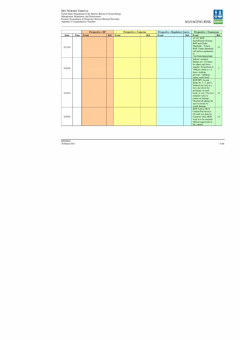
8/7/2019 DNV BOP report - Vol 2 (2)
http://slidepdf.com/reader/full/dnv-bop-report-vol-2-2 233/350
DET NORSKE VERITAS United States Department of the Interior, Bureau of Ocean EnergyManagement, Regulation, and Enforcement
Forensic Examination of Deepwater Horizon Blowout PreventerAppendix F Comprehensive Timeline
EP030842
20 March 2011
Perspective = BP Perspective = Cameron Perspective = Regulatory Sour
Date Time Event Ref. Event Ref. Event Re
3/17/10
3/18/10
3/19/10
3/19/10
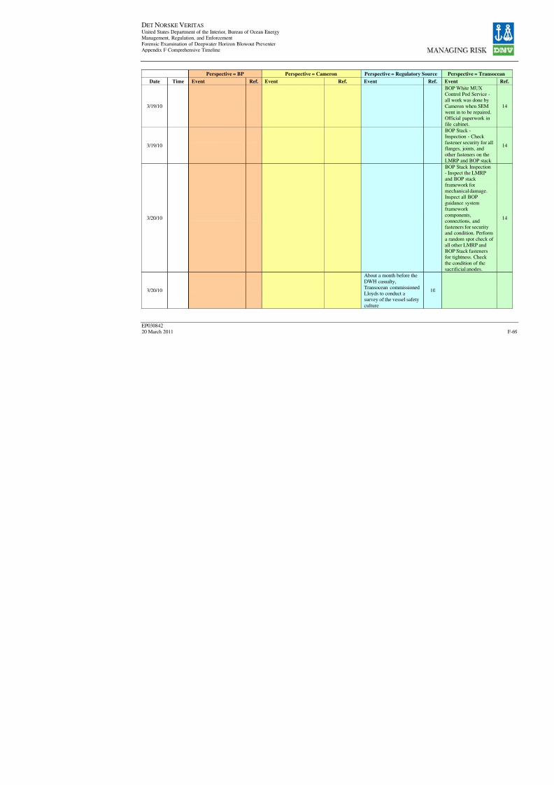
8/7/2019 DNV BOP report - Vol 2 (2)
http://slidepdf.com/reader/full/dnv-bop-report-vol-2-2 234/350
DET NORSKE VERITAS United States Department of the Interior, Bureau of Ocean EnergyManagement, Regulation, and Enforcement
Forensic Examination of Deepwater Horizon Blowout PreventerAppendix F Comprehensive Timeline
EP030842
20 March 2011
Perspective = BP Perspective = Cameron Perspective = Regulatory Sour
Date Time Event Ref. Event Ref. Event Re
3/19/10
3/19/10
3/20/10
3/20/10
About a month before the
DWH casualty,Transocean commissionedLloyds to conduct asurvey of the vessel safety
culture
1

8/7/2019 DNV BOP report - Vol 2 (2)
http://slidepdf.com/reader/full/dnv-bop-report-vol-2-2 235/350
DET NORSKE VERITAS United States Department of the Interior, Bureau of Ocean EnergyManagement, Regulation, and Enforcement
Forensic Examination of Deepwater Horizon Blowout PreventerAppendix F Comprehensive Timeline
EP030842
20 March 2011
Perspective = BP Perspective = Cameron Perspective = Regulatory Sour
Date Time Event Ref. Event Ref. Event Re
3/20/10
3/21/10
3/21/10
3/21/10
3/22/10
3/22/10

8/7/2019 DNV BOP report - Vol 2 (2)
http://slidepdf.com/reader/full/dnv-bop-report-vol-2-2 236/350
DET NORSKE VERITAS United States Department of the Interior, Bureau of Ocean EnergyManagement, Regulation, and Enforcement
Forensic Examination of Deepwater Horizon Blowout PreventerAppendix F Comprehensive Timeline
EP030842
20 March 2011
Perspective = BP Perspective = Cameron Perspective = Regulatory Sour
Date Time Event Ref. Event Ref. Event Re
3/26/10 00:00
3/26/10 14:30
3/26/10 15:30
3/26/10 16:22

8/7/2019 DNV BOP report - Vol 2 (2)
http://slidepdf.com/reader/full/dnv-bop-report-vol-2-2 237/350
DET NORSKE VERITAS United States Department of the Interior, Bureau of Ocean EnergyManagement, Regulation, and Enforcement
Forensic Examination of Deepwater Horizon Blowout PreventerAppendix F Comprehensive Timeline
EP030842
20 March 2011
Perspective = BP Perspective = Cameron Perspective = Regulatory Sour
Date Time Event Ref. Event Ref. Event Re
3/26/10 22:00
3/26/10
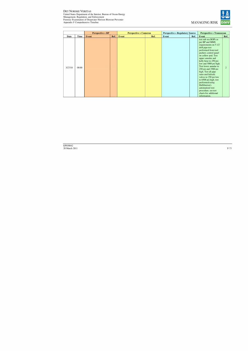
8/7/2019 DNV BOP report - Vol 2 (2)
http://slidepdf.com/reader/full/dnv-bop-report-vol-2-2 238/350
DET NORSKE VERITAS United States Department of the Interior, Bureau of Ocean EnergyManagement, Regulation, and Enforcement
Forensic Examination of Deepwater Horizon Blowout PreventerAppendix F Comprehensive Timeline
EP030842
20 March 2011
Perspective = BP Perspective = Cameron Perspective = Regulatory Sour
Date Time Event Ref. Event Ref. Event Re
3/27/10 00:00

8/7/2019 DNV BOP report - Vol 2 (2)
http://slidepdf.com/reader/full/dnv-bop-report-vol-2-2 239/350
DET NORSKE VERITAS United States Department of the Interior, Bureau of Ocean EnergyManagement, Regulation, and Enforcement
Forensic Examination of Deepwater Horizon Blowout PreventerAppendix F Comprehensive Timeline
EP030842
20 March 2011
Perspective = BP Perspective = Cameron Perspective = Regulatory Sour
Date Time Event Ref. Event Ref. Event Re
3/27/10 04:30
3/27/10 08:00
3/27/10 16:30
3/27/10

8/7/2019 DNV BOP report - Vol 2 (2)
http://slidepdf.com/reader/full/dnv-bop-report-vol-2-2 240/350
DET NORSKE VERITAS United States Department of the Interior, Bureau of Ocean EnergyManagement, Regulation, and Enforcement
Forensic Examination of Deepwater Horizon Blowout PreventerAppendix F Comprehensive Timeline
EP030842
20 March 2011
Perspective = BP Perspective = Cameron Perspective = Regulatory Sour
Date Time Event Ref. Event Ref. Event Re
3/27/10
3/28/10
3/28/10
3/28/10
3/29/10
3/30/10

8/7/2019 DNV BOP report - Vol 2 (2)
http://slidepdf.com/reader/full/dnv-bop-report-vol-2-2 241/350
DET NORSKE VERITAS United States Department of the Interior, Bureau of Ocean EnergyManagement, Regulation, and Enforcement
Forensic Examination of Deepwater Horizon Blowout PreventerAppendix F Comprehensive Timeline
EP030842
20 March 2011
Perspective = BP Perspective = Cameron Perspective = Regulatory Sour
Date Time Event Ref. Event Ref. Event Re
3/30/10
3/31/10
4/1/10 00:00
4/1/10 12:00
4/1/10MMS Inspection of Deep
Water Horizon9
4/2/10 03:30
4/2/10 09:00

8/7/2019 DNV BOP report - Vol 2 (2)
http://slidepdf.com/reader/full/dnv-bop-report-vol-2-2 242/350

8/7/2019 DNV BOP report - Vol 2 (2)
http://slidepdf.com/reader/full/dnv-bop-report-vol-2-2 243/350
DET NORSKE VERITAS United States Department of the Interior, Bureau of Ocean EnergyManagement, Regulation, and Enforcement
Forensic Examination of Deepwater Horizon Blowout PreventerAppendix F Comprehensive Timeline
EP030842
20 March 2011
Perspective = BP Perspective = Cameron Perspective = Regulatory Sour
Date Time Event Ref. Event Ref. Event Re
4/3/10 04:16
4/3/10 04:28
4/3/10 04:52
4/3/10 05:10
4/3/10 05:30
4/3/10 05:36
4/3/10 06:25
4/3/10 06:42
4/3/10 06:47
4/3/10 07:41
4/3/10 08:23
4/3/10 21:00

8/7/2019 DNV BOP report - Vol 2 (2)
http://slidepdf.com/reader/full/dnv-bop-report-vol-2-2 244/350
DET NORSKE VERITAS United States Department of the Interior, Bureau of Ocean EnergyManagement, Regulation, and Enforcement
Forensic Examination of Deepwater Horizon Blowout PreventerAppendix F Comprehensive Timeline
EP030842
20 March 2011
Perspective = BP Perspective = Cameron Perspective = Regulatory Sour
Date Time Event Ref. Event Ref. Event Re
4/5/10
Stripped drill pipethrough upper annularpreventer from 17,146
ft to 14,937 ft whileaddressing wellborelosses [4/5/10 to 4/6/10]
19
4/7/10 03:00
4/7/10 13:00
4/7/10 13:30
4/9/10"the well was drilled toa final depth of 18,360ft."
19
4/9/10
4/9/10"well reached totaldepth"
19

8/7/2019 DNV BOP report - Vol 2 (2)
http://slidepdf.com/reader/full/dnv-bop-report-vol-2-2 245/350
DET NORSKE VERITAS United States Department of the Interior, Bureau of Ocean EnergyManagement, Regulation, and Enforcement
Forensic Examination of Deepwater Horizon Blowout PreventerAppendix F Comprehensive Timeline
EP030842
20 March 2011
Perspective = BP Perspective = Cameron Perspective = Regulatory Sour
Date Time Event Ref. Event Ref. Event Re
4/10/10 00:00
4/10/10 03:30

8/7/2019 DNV BOP report - Vol 2 (2)
http://slidepdf.com/reader/full/dnv-bop-report-vol-2-2 246/350
DET NORSKE VERITAS United States Department of the Interior, Bureau of Ocean EnergyManagement, Regulation, and Enforcement
Forensic Examination of Deepwater Horizon Blowout PreventerAppendix F Comprehensive Timeline
EP030842
20 March 2011
Perspective = BP Perspective = Cameron Perspective = Regulatory Sour
Date Time Event Ref. Event Ref. Event Re
4/10/10 04:00
4/10/10 04:30
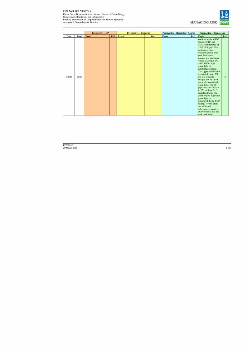
8/7/2019 DNV BOP report - Vol 2 (2)
http://slidepdf.com/reader/full/dnv-bop-report-vol-2-2 247/350
DET NORSKE VERITAS United States Department of the Interior, Bureau of Ocean EnergyManagement, Regulation, and Enforcement
Forensic Examination of Deepwater Horizon Blowout PreventerAppendix F Comprehensive Timeline
EP030842
20 March 2011
Perspective = BP Perspective = Cameron Perspective = Regulatory Sour
Date Time Event Ref. Event Ref. Event Re
4/10/10 05:00
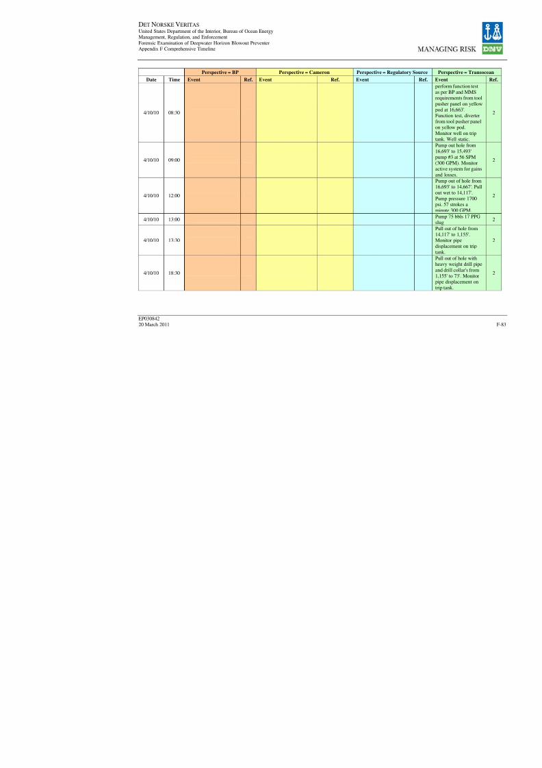
8/7/2019 DNV BOP report - Vol 2 (2)
http://slidepdf.com/reader/full/dnv-bop-report-vol-2-2 248/350
DET NORSKE VERITAS United States Department of the Interior, Bureau of Ocean EnergyManagement, Regulation, and Enforcement
Forensic Examination of Deepwater Horizon Blowout PreventerAppendix F Comprehensive Timeline
EP030842
20 March 2011
Perspective = BP Perspective = Cameron Perspective = Regulatory Sour
Date Time Event Ref. Event Ref. Event Re
4/10/10 08:30
4/10/10 09:00
4/10/10 12:00
4/10/10 13:00
4/10/10 13:30
4/10/10 18:30

8/7/2019 DNV BOP report - Vol 2 (2)
http://slidepdf.com/reader/full/dnv-bop-report-vol-2-2 249/350
DET NORSKE VERITAS United States Department of the Interior, Bureau of Ocean EnergyManagement, Regulation, and Enforcement
Forensic Examination of Deepwater Horizon Blowout PreventerAppendix F Comprehensive Timeline
EP030842
20 March 2011
Perspective = BP Perspective = Cameron Perspective = Regulatory Sour
Date Time Event Ref. Event Ref. Event Re
4/10/10 19:30
4/10/10 20:00
4/10/10 20:30
4/10/10 21:00
4/10/10 23:00
4/11/10 00:00
4/11/10 02:00
4/11/10 03:30

8/7/2019 DNV BOP report - Vol 2 (2)
http://slidepdf.com/reader/full/dnv-bop-report-vol-2-2 250/350
DET NORSKE VERITAS United States Department of the Interior, Bureau of Ocean EnergyManagement, Regulation, and Enforcement
Forensic Examination of Deepwater Horizon Blowout PreventerAppendix F Comprehensive Timeline
EP030842
20 March 2011
Perspective = BP Perspective = Cameron Perspective = Regulatory Sour
Date Time Event Ref. Event Ref. Event Re
4/11/10 05:30
4/11/10 06:00
4/11/10 06:30
4/11/10 09:00
4/11/10 12:00
4/11/10 12:30

8/7/2019 DNV BOP report - Vol 2 (2)
http://slidepdf.com/reader/full/dnv-bop-report-vol-2-2 251/350
DET NORSKE VERITAS United States Department of the Interior, Bureau of Ocean EnergyManagement, Regulation, and Enforcement
Forensic Examination of Deepwater Horizon Blowout PreventerAppendix F Comprehensive Timeline
EP030842
20 March 2011
Perspective = BP Perspective = Cameron Perspective = Regulatory Sour
Date Time Event Ref. Event Ref. Event Re
4/11/10 14:00
4/11/10 14:30
4/11/10 16:30
4/11/10 19:00
4/12/10 00:00
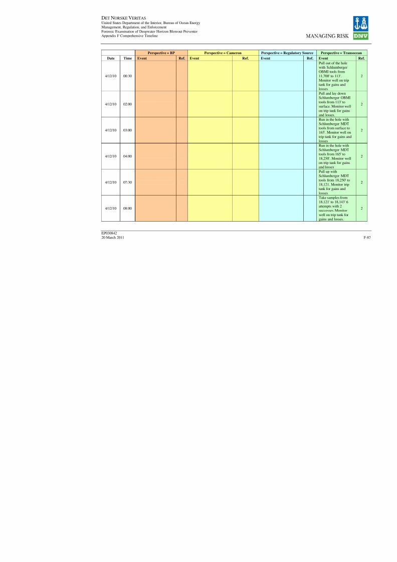
8/7/2019 DNV BOP report - Vol 2 (2)
http://slidepdf.com/reader/full/dnv-bop-report-vol-2-2 252/350
DET NORSKE VERITAS United States Department of the Interior, Bureau of Ocean EnergyManagement, Regulation, and Enforcement
Forensic Examination of Deepwater Horizon Blowout PreventerAppendix F Comprehensive Timeline
EP030842
20 March 2011
Perspective = BP Perspective = Cameron Perspective = Regulatory Sour
Date Time Event Ref. Event Ref. Event Re
4/12/10 00:30
4/12/10 02:00
4/12/10 03:00
4/12/10 04:00
4/12/10 07:30
4/12/10 08:00

8/7/2019 DNV BOP report - Vol 2 (2)
http://slidepdf.com/reader/full/dnv-bop-report-vol-2-2 253/350
DET NORSKE VERITAS United States Department of the Interior, Bureau of Ocean EnergyManagement, Regulation, and Enforcement
Forensic Examination of Deepwater Horizon Blowout PreventerAppendix F Comprehensive Timeline
EP030842
20 March 2011
Perspective = BP Perspective = Cameron Perspective = Regulatory Sour
Date Time Event Ref. Event Ref. Event Re
4/12/10 12:00
4/13/10
4/13/10 00:00
4/13/10 03:00
4/13/10 06:00
4/13/10 07:00
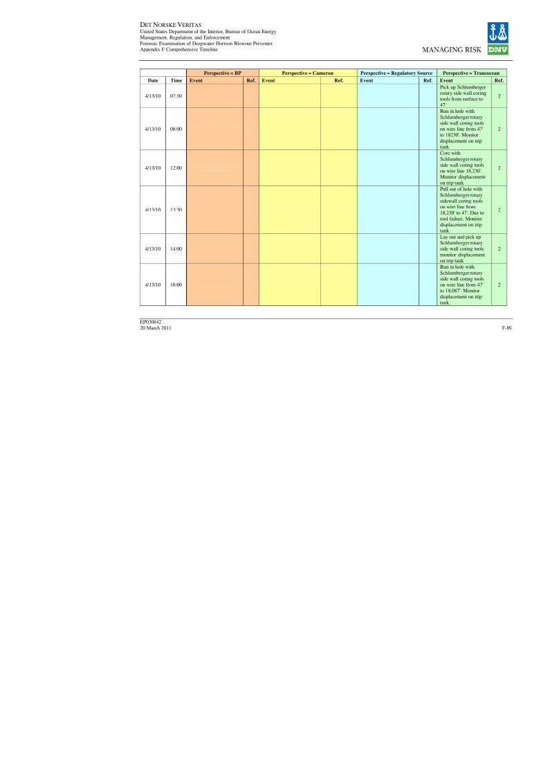
8/7/2019 DNV BOP report - Vol 2 (2)
http://slidepdf.com/reader/full/dnv-bop-report-vol-2-2 254/350
DET NORSKE VERITAS United States Department of the Interior, Bureau of Ocean EnergyManagement, Regulation, and Enforcement
Forensic Examination of Deepwater Horizon Blowout PreventerAppendix F Comprehensive Timeline
EP030842
20 March 2011
Perspective = BP Perspective = Cameron Perspective = Regulatory Sour
Date Time Event Ref. Event Ref. Event Re
4/13/10 07:30
4/13/10 08:00
4/13/10 12:00
4/13/10 13:30
4/13/10 14:00
4/13/10 18:00
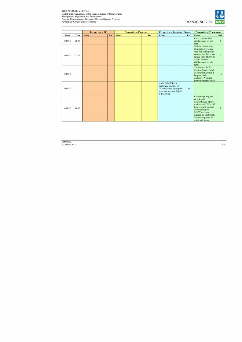
8/7/2019 DNV BOP report - Vol 2 (2)
http://slidepdf.com/reader/full/dnv-bop-report-vol-2-2 255/350
DET NORSKE VERITAS United States Department of the Interior, Bureau of Ocean EnergyManagement, Regulation, and Enforcement
Forensic Examination of Deepwater Horizon Blowout PreventerAppendix F Comprehensive Timeline
EP030842
20 March 2011
Perspective = BP Perspective = Cameron Perspective = Regulatory Sour
Date Time Event Ref. Event Ref. Event Re
4/13/10 20:30
4/13/10 22:00
4/13/10
4/14/10
Audit (ModUSpec)
performed in April of 2010 indicated spare podswere not operable [April1-14, 2010]
1
4/14/10 00:00

8/7/2019 DNV BOP report - Vol 2 (2)
http://slidepdf.com/reader/full/dnv-bop-report-vol-2-2 256/350
DET NORSKE VERITAS United States Department of the Interior, Bureau of Ocean EnergyManagement, Regulation, and Enforcement
Forensic Examination of Deepwater Horizon Blowout PreventerAppendix F Comprehensive Timeline
EP030842
20 March 2011
Perspective = BP Perspective = Cameron Perspective = Regulatory Sour
Date Time Event Ref. Event Ref. Event Re
4/14/10 01:30
4/14/10 02:00
4/14/10 03:00
4/14/10 05:30
4/14/10 12:00
4/14/10 13:30
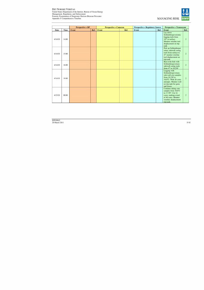
8/7/2019 DNV BOP report - Vol 2 (2)
http://slidepdf.com/reader/full/dnv-bop-report-vol-2-2 257/350
DET NORSKE VERITAS United States Department of the Interior, Bureau of Ocean EnergyManagement, Regulation, and Enforcement
Forensic Examination of Deepwater Horizon Blowout PreventerAppendix F Comprehensive Timeline
EP030842
20 March 2011
Perspective = BP Perspective = Cameron Perspective = Regulatory Sour
Date Time Event Ref. Event Ref. Event Re
4/14/10 14:00
4/14/10 15:00
4/14/10 16:00
4/14/10 18:00
4/15/10 00:00
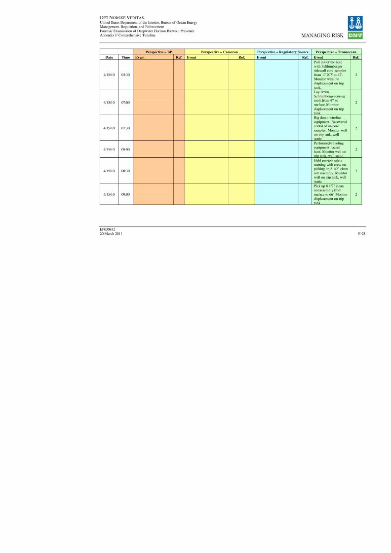
8/7/2019 DNV BOP report - Vol 2 (2)
http://slidepdf.com/reader/full/dnv-bop-report-vol-2-2 258/350
DET NORSKE VERITAS United States Department of the Interior, Bureau of Ocean EnergyManagement, Regulation, and Enforcement
Forensic Examination of Deepwater Horizon Blowout PreventerAppendix F Comprehensive Timeline
EP030842
20 March 2011
Perspective = BP Perspective = Cameron Perspective = Regulatory Sour
Date Time Event Ref. Event Ref. Event Re
4/15/10 03:30
4/15/10 07:00
4/15/10 07:30
4/15/10 08:00
4/15/10 08:30
4/15/10 09:00

8/7/2019 DNV BOP report - Vol 2 (2)
http://slidepdf.com/reader/full/dnv-bop-report-vol-2-2 259/350
DET NORSKE VERITAS United States Department of the Interior, Bureau of Ocean EnergyManagement, Regulation, and Enforcement
Forensic Examination of Deepwater Horizon Blowout PreventerAppendix F Comprehensive Timeline
EP030842
20 March 2011
Perspective = BP Perspective = Cameron Perspective = Regulatory Sour
Date Time Event Ref. Event Ref. Event Re
4/15/10 09:30
4/15/10 10:30
4/15/10 11:00
4/15/10 11:30
4/15/10 12:00
4/15/10 12:30
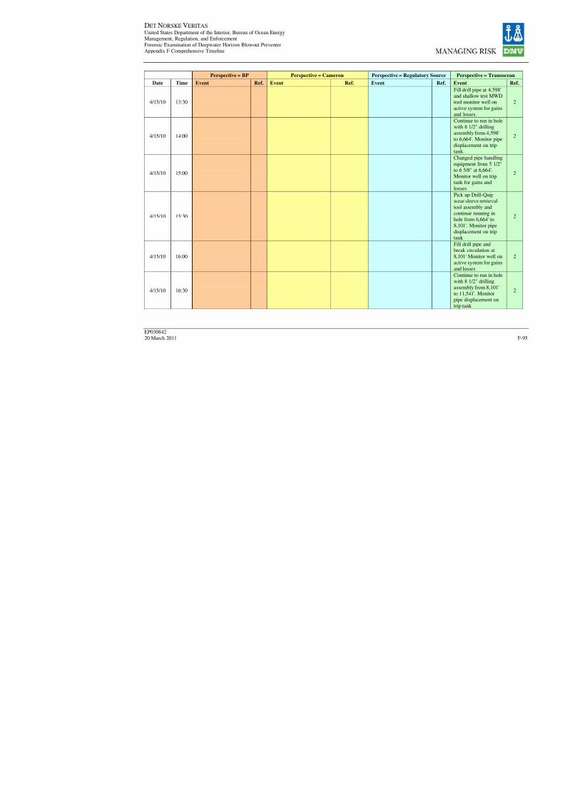
8/7/2019 DNV BOP report - Vol 2 (2)
http://slidepdf.com/reader/full/dnv-bop-report-vol-2-2 260/350
DET NORSKE VERITAS United States Department of the Interior, Bureau of Ocean EnergyManagement, Regulation, and Enforcement
Forensic Examination of Deepwater Horizon Blowout PreventerAppendix F Comprehensive Timeline
EP030842
20 March 2011
Perspective = BP Perspective = Cameron Perspective = Regulatory Sour
Date Time Event Ref. Event Ref. Event Re
4/15/10 13:30
4/15/10 14:00
4/15/10 15:00
4/15/10 15:30
4/15/10 16:00
4/15/10 16:30

8/7/2019 DNV BOP report - Vol 2 (2)
http://slidepdf.com/reader/full/dnv-bop-report-vol-2-2 261/350
DET NORSKE VERITAS United States Department of the Interior, Bureau of Ocean EnergyManagement, Regulation, and Enforcement
Forensic Examination of Deepwater Horizon Blowout PreventerAppendix F Comprehensive Timeline
EP030842
20 March 2011
Perspective = BP Perspective = Cameron Perspective = Regulatory Sour
Date Time Event Ref. Event Ref. Event Re
4/15/10 17:30
4/15/10 18:00
4/15/10 20:00
4/15/10 21:00
4/15/10 23:00

8/7/2019 DNV BOP report - Vol 2 (2)
http://slidepdf.com/reader/full/dnv-bop-report-vol-2-2 262/350
DET NORSKE VERITAS United States Department of the Interior, Bureau of Ocean EnergyManagement, Regulation, and Enforcement
Forensic Examination of Deepwater Horizon Blowout PreventerAppendix F Comprehensive Timeline
EP030842
20 March 2011
Perspective = BP Perspective = Cameron Perspective = Regulatory Sour
Date Time Event Ref. Event Ref. Event Re
4/16/10
"MMS approved theprocedure for temporaryabandonment of the
well"
19
4/18/10 00:00
4/18/10 00:30"the rig started runningthe 9 7/8 in x 7 in longstring"
19
4/18/10 01:00
4/18/10 03:00
4/18/10 03:30
4/18/10 12:00

8/7/2019 DNV BOP report - Vol 2 (2)
http://slidepdf.com/reader/full/dnv-bop-report-vol-2-2 263/350
DET NORSKE VERITAS United States Department of the Interior, Bureau of Ocean EnergyManagement, Regulation, and Enforcement
Forensic Examination of Deepwater Horizon Blowout PreventerAppendix F Comprehensive Timeline
EP030842
20 March 2011
Perspective = BP Perspective = Cameron Perspective = Regulatory Sour
Date Time Event Ref. Event Ref. Event Re
4/18/10 12:30
4/18/10 13:30
4/18/10 14:00
4/18/10 15:00
4/18/10 15:30

8/7/2019 DNV BOP report - Vol 2 (2)
http://slidepdf.com/reader/full/dnv-bop-report-vol-2-2 264/350
DET NORSKE VERITAS United States Department of the Interior, Bureau of Ocean EnergyManagement, Regulation, and Enforcement
Forensic Examination of Deepwater Horizon Blowout PreventerAppendix F Comprehensive Timeline
EP030842
20 March 2011
Perspective = BP Perspective = Cameron Perspective = Regulatory Sour
Date Time Event Ref. Event Ref. Event Re
4/18/10 17:00
4/18/10
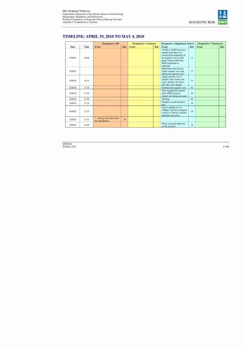
8/7/2019 DNV BOP report - Vol 2 (2)
http://slidepdf.com/reader/full/dnv-bop-report-vol-2-2 265/350
DET NORSKE VERITAS United States Department of the Interior, Bureau of Ocean EnergyManagement, Regulation, and Enforcement
Forensic Examination of Deepwater Horizon Blowout PreventerAppendix F Comprehensive Timeline
EP030842
20 March 2011
TIMELINE: APRIL 19, 2010 TO MAY 4, 2010
Perspective = BP Perspective = Cameron Perspective = Regulatory Sour
Date Time Event Ref. Event Ref. Event R
4/20/10 16:00
[15:00 to 16:00] the lowerannular preventer was
closed at the beginning of the negative test in frompanel without difficulty.BOP responded as
expected
1
4/20/10[Date/Time Not Given]Upper annular was usedduring the negative tests
1
4/20/10 16:15
Approximately 10-15
minutes after closing thelower annular, the lowerkill valve was opened
1
4/20/10 17:30 Finished first negative test 1
4/20/10 17:30
They bumped the annularup to 1900 to keep it
closed; not losing any mud1
4/20/10 17:50 All Stop 1
4/20/10 21:10Finished second negativetest
1
4/20/10 21:25
Lower annular was at1900psi and Chris droppedit back to 1500 psi (normal
operating pressure)
1
4/20/10 21:31 "…the rig crew shut downthe mud pumps"
19
4/20/10 21:40Water and mud observedon the rig floor
1
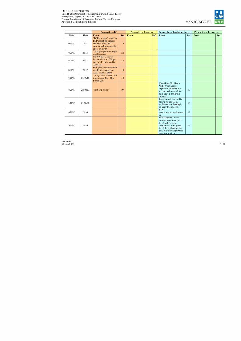
8/7/2019 DNV BOP report - Vol 2 (2)
http://slidepdf.com/reader/full/dnv-bop-report-vol-2-2 266/350
DET NORSKE VERITAS United States Department of the Interior, Bureau of Ocean EnergyManagement, Regulation, and Enforcement
Forensic Examination of Deepwater Horizon Blowout PreventerAppendix F Comprehensive Timeline
EP030842
20 March 2011
Perspective = BP Perspective = Cameron Perspective = Regulatory Sour
Date Time Event Ref. Event Ref. Event R
4/20/10 21:41
"BOP activated" - annularBOP closed but appearsnot have sealed the
annular; unknown whetherupper or lower
19
4/20/10 21:43Stand pipe pressure beginsrapid increase
20
4/20/10 21:46
the drill pipe pressureincreased from 1,200 psiand rapidly increased to
5,556 psi
40
4/20/10 21:47Drill pipe pressure startedrapidly increasing from1,200 psi to 5,730psi
19
4/20/10 21:49:15
Sperry-Sun real-time data
transmission lost - RigPower Lost
40
4/20/10 21:49:20 "First Explosion" 19
[Date/Time Not Given]Well, it was a majorexplosion, followed by asecond explosion, a lot of
back draft in the livingquarters.
1
4/20/10 21:50:00
Received call that well isblown out and JasonAnderson was shutting it
in (prior to explosion)
1
4/20/10 21:56EDSexercised/activated/sheared
up
1
4/20/10 21:56
Panel indicated lower
annular was closed (redlight) and the upperannular was open (greenlight). Everything for the
rams was showing open inthe green position
1

8/7/2019 DNV BOP report - Vol 2 (2)
http://slidepdf.com/reader/full/dnv-bop-report-vol-2-2 267/350
DET NORSKE VERITAS United States Department of the Interior, Bureau of Ocean EnergyManagement, Regulation, and Enforcement
Forensic Examination of Deepwater Horizon Blowout PreventerAppendix F Comprehensive Timeline
EP030842
20 March 2011
Perspective = BP Perspective = Cameron Perspective = Regulatory Sour
Date Time Event Ref. Event Ref. Event R
4/20/10 21:56
EDS buttons pushed by
Subsea Engineer. EDSannounced by Captain tobe 21:56.
31
While on the bridge,before hitting the EDS,Chris Pleasant looked at
the panel and observed thatit indicated the lowerannular was closed (theonly things closed)
1
4/20/10 21:56
After activating the EDSbutton, the light for the
BSR was green then itwent to red and then he
doesn't know whathappened. Looked at theflow meters and neithershowed movement.
1
4/20/10 22:28
4/20/10 23:35
4/20/10 23:46
4/20/10 VIP visit to DWH 1
4/20/10LMRP did not unlatch(timed to occur 25 secafter initiation of EDS)
31
4/20/10 Rig drifted off location 19

8/7/2019 DNV BOP report - Vol 2 (2)
http://slidepdf.com/reader/full/dnv-bop-report-vol-2-2 268/350
DET NORSKE VERITAS United States Department of the Interior, Bureau of Ocean EnergyManagement, Regulation, and Enforcement
Forensic Examination of Deepwater Horizon Blowout PreventerAppendix F Comprehensive Timeline
EP030842
20 March 2011
Perspective = BP Perspective = Cameron Perspective = Regulatory Sour
Date Time Event Ref. Event Ref. Event R
4/21/10 01:35
4/21/10 02:04

8/7/2019 DNV BOP report - Vol 2 (2)
http://slidepdf.com/reader/full/dnv-bop-report-vol-2-2 269/350
DET NORSKE VERITAS United States Department of the Interior, Bureau of Ocean EnergyManagement, Regulation, and Enforcement
Forensic Examination of Deepwater Horizon Blowout PreventerAppendix F Comprehensive Timeline
EP030842
20 March 2011
Perspective = BP Perspective = Cameron Perspective = Regulatory Sour
Date Time Event Ref. Event Ref. Event R
4/21/10 02:23
4/21/10 02:33
4/21/10 02:54
4/21/10 03:27
4/21/10 03:29

8/7/2019 DNV BOP report - Vol 2 (2)
http://slidepdf.com/reader/full/dnv-bop-report-vol-2-2 270/350
DET NORSKE VERITAS United States Department of the Interior, Bureau of Ocean EnergyManagement, Regulation, and Enforcement
Forensic Examination of Deepwater Horizon Blowout PreventerAppendix F Comprehensive Timeline
EP030842
20 March 2011
Perspective = BP Perspective = Cameron Perspective = Regulatory Sour
Date Time Event Ref. Event Ref. Event R
4/21/10 03:50
4/21/10 04:15
4/21/10 04:30
4/21/10 05:24
4/21/10 05:31
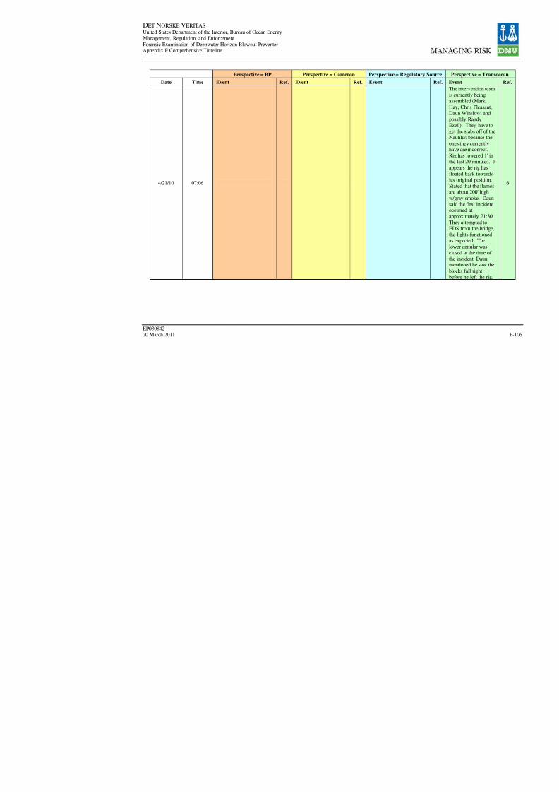
8/7/2019 DNV BOP report - Vol 2 (2)
http://slidepdf.com/reader/full/dnv-bop-report-vol-2-2 271/350
DET NORSKE VERITAS United States Department of the Interior, Bureau of Ocean EnergyManagement, Regulation, and Enforcement
Forensic Examination of Deepwater Horizon Blowout PreventerAppendix F Comprehensive Timeline
EP030842
20 March 2011
Perspective = BP Perspective = Cameron Perspective = Regulatory Sour
Date Time Event Ref. Event Ref. Event R
4/21/10 07:06

8/7/2019 DNV BOP report - Vol 2 (2)
http://slidepdf.com/reader/full/dnv-bop-report-vol-2-2 272/350
DET NORSKE VERITAS United States Department of the Interior, Bureau of Ocean EnergyManagement, Regulation, and Enforcement
Forensic Examination of Deepwater Horizon Blowout PreventerAppendix F Comprehensive Timeline
EP030842
20 March 2011
Perspective = BP Perspective = Cameron Perspective = Regulatory Sour
Date Time Event Ref. Event Ref. Event R
4/21/10 07:45
4/21/10 07:47
4/21/10 08:24
4/21/10 09:07
4/21/10 11:40
4/21/10 12:31
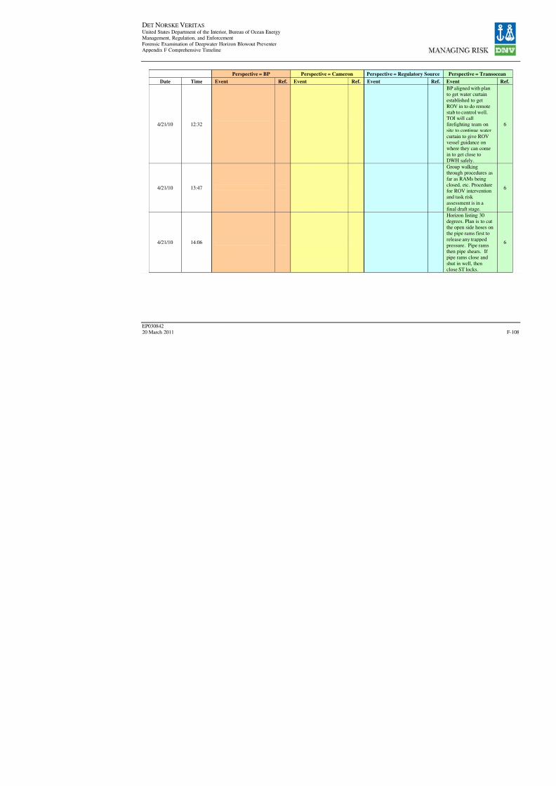
8/7/2019 DNV BOP report - Vol 2 (2)
http://slidepdf.com/reader/full/dnv-bop-report-vol-2-2 273/350
DET NORSKE VERITAS United States Department of the Interior, Bureau of Ocean EnergyManagement, Regulation, and Enforcement
Forensic Examination of Deepwater Horizon Blowout PreventerAppendix F Comprehensive Timeline
EP030842
20 March 2011
Perspective = BP Perspective = Cameron Perspective = Regulatory Sour
Date Time Event Ref. Event Ref. Event R
4/21/10 12:32
4/21/10 13:47
4/21/10 14:06
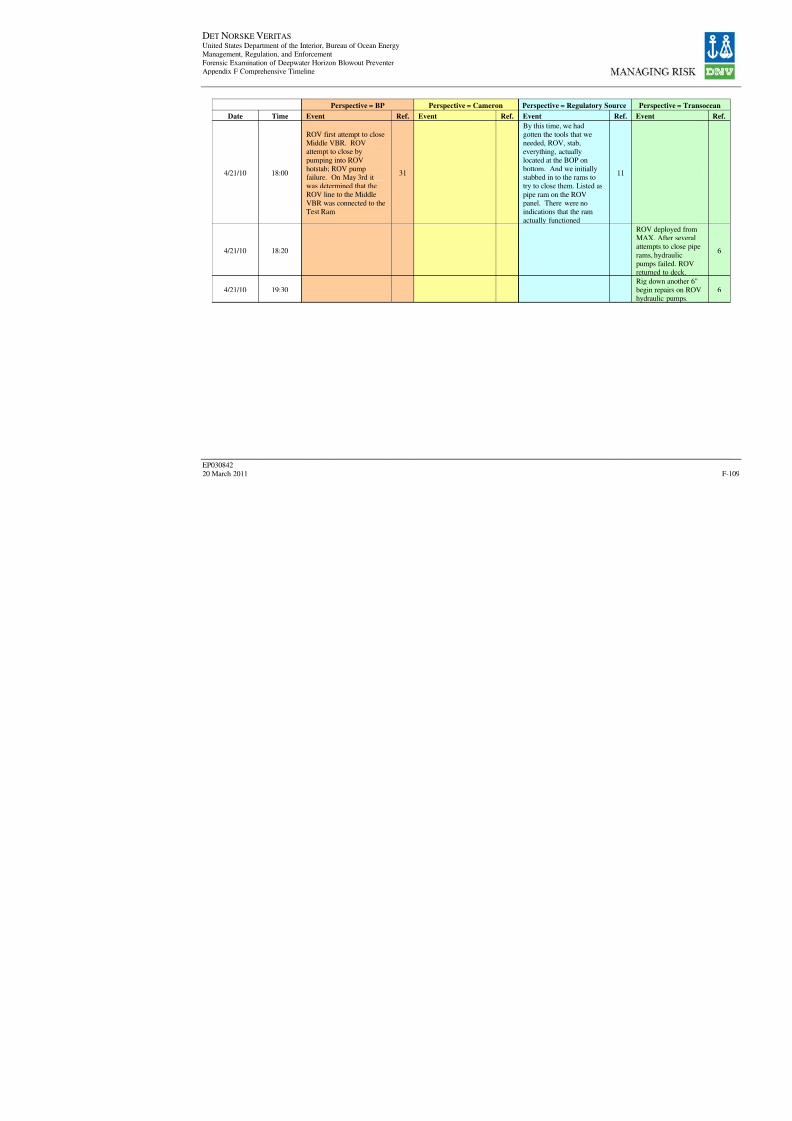
8/7/2019 DNV BOP report - Vol 2 (2)
http://slidepdf.com/reader/full/dnv-bop-report-vol-2-2 274/350
DET NORSKE VERITAS United States Department of the Interior, Bureau of Ocean EnergyManagement, Regulation, and Enforcement
Forensic Examination of Deepwater Horizon Blowout PreventerAppendix F Comprehensive Timeline
EP030842
20 March 2011
Perspective = BP Perspective = Cameron Perspective = Regulatory Sour
Date Time Event Ref. Event Ref. Event R
4/21/10 18:00
ROV first attempt to closeMiddle VBR. ROVattempt to close by
pumping into ROVhotstab; ROV pumpfailure. On May 3rd itwas determined that theROV line to the Middle
VBR was connected to theTest Ram
31
By this time, we hadgotten the tools that weneeded, ROV, stab,
everything, actuallylocated at the BOP onbottom. And we initiallystabbed in to the rams totry to close them. Listed as
pipe ram on the ROVpanel. There were noindications that the ram
actually functioned
1
4/21/10 18:20
4/21/10 19:30

8/7/2019 DNV BOP report - Vol 2 (2)
http://slidepdf.com/reader/full/dnv-bop-report-vol-2-2 275/350
DET NORSKE VERITAS United States Department of the Interior, Bureau of Ocean EnergyManagement, Regulation, and Enforcement
Forensic Examination of Deepwater Horizon Blowout PreventerAppendix F Comprehensive Timeline
EP030842
20 March 2011
Perspective = BP Perspective = Cameron Perspective = Regulatory Sour
Date Time Event Ref. Event Ref. Event R
4/21/10 20:49
4/21/10 21:00First attempt activate
autoshear - ROV unable tocut Shear Trigger Pin
31
ROV first attempt toactivate the autoshear.ROV attempted to cutshear trigger pin to activate
autoshear. ROV unable to
cut pin.
1
4/21/10 21:37

8/7/2019 DNV BOP report - Vol 2 (2)
http://slidepdf.com/reader/full/dnv-bop-report-vol-2-2 276/350
DET NORSKE VERITAS United States Department of the Interior, Bureau of Ocean EnergyManagement, Regulation, and Enforcement
Forensic Examination of Deepwater Horizon Blowout PreventerAppendix F Comprehensive Timeline
EP030842
20 March 2011
Perspective = BP Perspective = Cameron Perspective = Regulatory Sour
Date Time Event Ref. Event Ref. Event R
4/21/10 22:35
4/21/10 22:46
4/21/10 22:53
4/21/10 22:55
4/21/10 23:01
4/21/10 23:18
4/22/10 1:15
First attempt to close BSRvia hot stab - Lowpressure and flow,possible ST lock leak
31
Plug into hot stab andattempt to close shearrams. Unable to buildpressure. Low flow rate.
1

8/7/2019 DNV BOP report - Vol 2 (2)
http://slidepdf.com/reader/full/dnv-bop-report-vol-2-2 277/350
DET NORSKE VERITAS United States Department of the Interior, Bureau of Ocean EnergyManagement, Regulation, and Enforcement
Forensic Examination of Deepwater Horizon Blowout PreventerAppendix F Comprehensive Timeline
EP030842
20 March 2011
Perspective = BP Perspective = Cameron Perspective = Regulatory Sour
Date Time Event Ref. Event Ref. Event R
4/22/10 01:39
4/22/10 02:20
4/22/10 02:42

8/7/2019 DNV BOP report - Vol 2 (2)
http://slidepdf.com/reader/full/dnv-bop-report-vol-2-2 278/350
DET NORSKE VERITAS United States Department of the Interior, Bureau of Ocean EnergyManagement, Regulation, and Enforcement
Forensic Examination of Deepwater Horizon Blowout PreventerAppendix F Comprehensive Timeline
EP030842
20 March 2011
Perspective = BP Perspective = Cameron Perspective = Regulatory Sour
Date Time Event Ref. Event Ref. Event R
4/22/10 02:44

8/7/2019 DNV BOP report - Vol 2 (2)
http://slidepdf.com/reader/full/dnv-bop-report-vol-2-2 279/350
DET NORSKE VERITAS United States Department of the Interior, Bureau of Ocean EnergyManagement, Regulation, and Enforcement
Forensic Examination of Deepwater Horizon Blowout PreventerAppendix F Comprehensive Timeline
EP030842
20 March 2011
Perspective = BP Perspective = Cameron Perspective = Regulatory Sour
Date Time Event Ref. Event Ref. Event R
4/22/10 2:45
ROV first attempt tosimulate AMF("Deadman). ROV cut
pilot lines from rigidconduit manifold to bothpods, cut pressurebalanced oil filled (PBOF)cables from Subsea
Transducer Module(STM1) & STM2 to theSEM on both pods to
simulate "Deadman" andactivate BSRs. Threenecessary conditions for
AMF ("Deadman")
satisfied no later than thistime. BSR had not sealed;well continued to flow.
31
First attempt to fire the
deadman system. Notsuccessful, did not see anychanges once performedthose tasks.
1
4/22/10 02:56
4/22/10 02:59
4/22/10 03:42
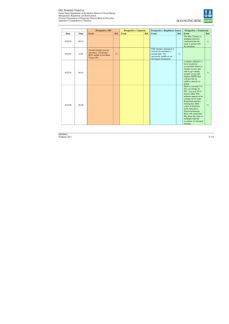
8/7/2019 DNV BOP report - Vol 2 (2)
http://slidepdf.com/reader/full/dnv-bop-report-vol-2-2 280/350
DET NORSKE VERITAS United States Department of the Interior, Bureau of Ocean EnergyManagement, Regulation, and Enforcement
Forensic Examination of Deepwater Horizon Blowout PreventerAppendix F Comprehensive Timeline
EP030842
20 March 2011
Perspective = BP Perspective = Cameron Perspective = Regulatory Sour
Date Time Event Ref. Event Ref. Event R
4/22/10 04:14
4/22/10 4:40
Second attempt activateautoshear - SS grinder -ROV unable to cut ShearTrigger Pin
31
Fifth attempt, attempted toactivate the autoshear asecond time. Nosuccessful, unable to cut
the trigger mechanism.
1
4/22/10 04:43
4/22/10 05:20
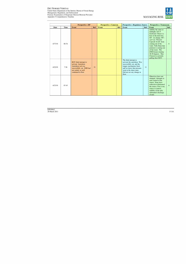
8/7/2019 DNV BOP report - Vol 2 (2)
http://slidepdf.com/reader/full/dnv-bop-report-vol-2-2 281/350
DET NORSKE VERITAS United States Department of the Interior, Bureau of Ocean EnergyManagement, Regulation, and Enforcement
Forensic Examination of Deepwater Horizon Blowout PreventerAppendix F Comprehensive Timeline
EP030842
20 March 2011
Perspective = BP Perspective = Cameron Perspective = Regulatory Sour
Date Time Event Ref. Event Ref. Event R
4/22/10 06:26
4/22/10 7:36
ROV third attempt toactivate Autoshear.Autoshear rod wassuccessfully cut. BSR had
not sealed, as wellcontinued to flow
31
The third attempt toactivate the autoshear. Wassuccessfully cut, and thetrigger mechanism fired,
and we know that pressurewent to the shear rams.Did not see any change inflow.
1
4/22/10 07:45
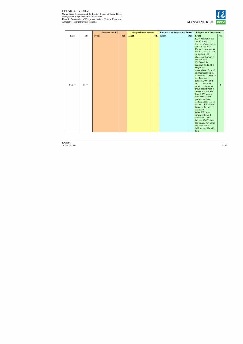
8/7/2019 DNV BOP report - Vol 2 (2)
http://slidepdf.com/reader/full/dnv-bop-report-vol-2-2 282/350
DET NORSKE VERITAS United States Department of the Interior, Bureau of Ocean EnergyManagement, Regulation, and Enforcement
Forensic Examination of Deepwater Horizon Blowout PreventerAppendix F Comprehensive Timeline
EP030842
20 March 2011
Perspective = BP Perspective = Cameron Perspective = Regulatory Sour
Date Time Event Ref. Event Ref. Event R
4/22/10 08:44

8/7/2019 DNV BOP report - Vol 2 (2)
http://slidepdf.com/reader/full/dnv-bop-report-vol-2-2 283/350
DET NORSKE VERITAS United States Department of the Interior, Bureau of Ocean EnergyManagement, Regulation, and Enforcement
Forensic Examination of Deepwater Horizon Blowout PreventerAppendix F Comprehensive Timeline
EP030842
20 March 2011
Perspective = BP Perspective = Cameron Perspective = Regulatory Sour
Date Time Event Ref. Event Ref. Event R
4/22/10 09:19
4/22/10 09:43
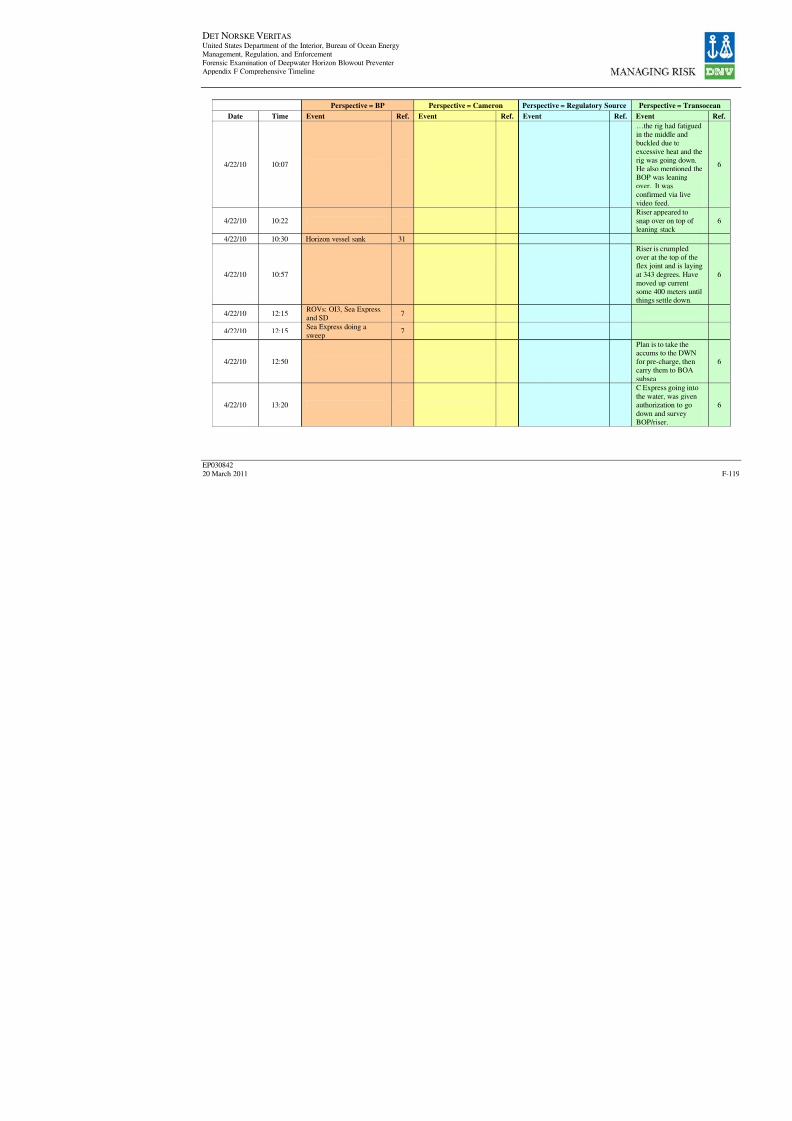
8/7/2019 DNV BOP report - Vol 2 (2)
http://slidepdf.com/reader/full/dnv-bop-report-vol-2-2 284/350
DET NORSKE VERITAS United States Department of the Interior, Bureau of Ocean EnergyManagement, Regulation, and Enforcement
Forensic Examination of Deepwater Horizon Blowout PreventerAppendix F Comprehensive Timeline
EP030842
20 March 2011
Perspective = BP Perspective = Cameron Perspective = Regulatory Sour
Date Time Event Ref. Event Ref. Event R
4/22/10 10:07
4/22/10 10:22
4/22/10 10:30 Horizon vessel sank 31
4/22/10 10:57
4/22/10 12:15ROVs: OI3, Sea Express,
and SD7
4/22/10 12:15Sea Express doing a
sweep7
4/22/10 12:50
4/22/10 13:20

8/7/2019 DNV BOP report - Vol 2 (2)
http://slidepdf.com/reader/full/dnv-bop-report-vol-2-2 285/350
DET NORSKE VERITAS United States Department of the Interior, Bureau of Ocean EnergyManagement, Regulation, and Enforcement
Forensic Examination of Deepwater Horizon Blowout PreventerAppendix F Comprehensive Timeline
EP030842
20 March 2011
Perspective = BP Perspective = Cameron Perspective = Regulatory Sour
Date Time Event Ref. Event Ref. Event R
4/22/10 16:00
4/22/10 20:30
4/22/10 20:56
4/22/10 22:30

8/7/2019 DNV BOP report - Vol 2 (2)
http://slidepdf.com/reader/full/dnv-bop-report-vol-2-2 286/350
DET NORSKE VERITAS United States Department of the Interior, Bureau of Ocean EnergyManagement, Regulation, and Enforcement
Forensic Examination of Deepwater Horizon Blowout PreventerAppendix F Comprehensive Timeline
EP030842
20 March 2011
Perspective = BP Perspective = Cameron Perspective = Regulatory Sour
Date Time Event Ref. Event Ref. Event R
4/23/10 05:10
4/23/10 07:45
4/23/10 11:15

8/7/2019 DNV BOP report - Vol 2 (2)
http://slidepdf.com/reader/full/dnv-bop-report-vol-2-2 287/350
DET NORSKE VERITAS United States Department of the Interior, Bureau of Ocean EnergyManagement, Regulation, and Enforcement
Forensic Examination of Deepwater Horizon Blowout PreventerAppendix F Comprehensive Timeline
EP030842
20 March 2011
Perspective = BP Perspective = Cameron Perspective = Regulatory Sour
Date Time Event Ref. Event Ref. Event R
4/23/10 11:31
4/23/10 15:32
4/23/10 15:45
4/24/10 01:05
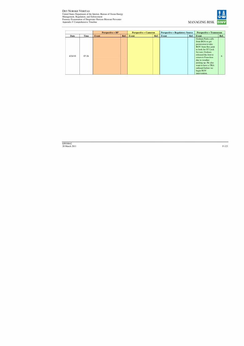
8/7/2019 DNV BOP report - Vol 2 (2)
http://slidepdf.com/reader/full/dnv-bop-report-vol-2-2 288/350
DET NORSKE VERITAS United States Department of the Interior, Bureau of Ocean EnergyManagement, Regulation, and Enforcement
Forensic Examination of Deepwater Horizon Blowout PreventerAppendix F Comprehensive Timeline
EP030842
20 March 2011
Perspective = BP Perspective = Cameron Perspective = Regulatory Sour
Date Time Event Ref. Event Ref. Event R
4/24/10 07:26

8/7/2019 DNV BOP report - Vol 2 (2)
http://slidepdf.com/reader/full/dnv-bop-report-vol-2-2 289/350
DET NORSKE VERITAS United States Department of the Interior, Bureau of Ocean EnergyManagement, Regulation, and Enforcement
Forensic Examination of Deepwater Horizon Blowout PreventerAppendix F Comprehensive Timeline
EP030842
20 March 2011
Perspective = BP Perspective = Cameron Perspective = Regulatory Sour
Date Time Event Ref. Event Ref. Event R
4/24/10 13:05
4/25/10 00:57

8/7/2019 DNV BOP report - Vol 2 (2)
http://slidepdf.com/reader/full/dnv-bop-report-vol-2-2 290/350
DET NORSKE VERITAS United States Department of the Interior, Bureau of Ocean EnergyManagement, Regulation, and Enforcement
Forensic Examination of Deepwater Horizon Blowout PreventerAppendix F Comprehensive Timeline
EP030842
20 March 2011
Perspective = BP Perspective = Cameron Perspective = Regulatory Sour
Date Time Event Ref. Event Ref. Event R
4/25/10 01:09

8/7/2019 DNV BOP report - Vol 2 (2)
http://slidepdf.com/reader/full/dnv-bop-report-vol-2-2 291/350
DET NORSKE VERITAS United States Department of the Interior, Bureau of Ocean EnergyManagement, Regulation, and Enforcement
Forensic Examination of Deepwater Horizon Blowout PreventerAppendix F Comprehensive Timeline
EP030842
20 March 2011
Perspective = BP Perspective = Cameron Perspective = Regulatory Sour
Date Time Event Ref. Event Ref. Event R
4/25/10 01:49

8/7/2019 DNV BOP report - Vol 2 (2)
http://slidepdf.com/reader/full/dnv-bop-report-vol-2-2 292/350
DET NORSKE VERITAS United States Department of the Interior, Bureau of Ocean EnergyManagement, Regulation, and Enforcement
Forensic Examination of Deepwater Horizon Blowout PreventerAppendix F Comprehensive Timeline
EP030842
20 March 2011
Perspective = BP Perspective = Cameron Perspective = Regulatory Sour
Date Time Event Ref. Event Ref. Event R
4/25/10 04:30
4/25/10 07:23
4/25/10 07:42
4/25/10 08:15
4/25/10 08:40

8/7/2019 DNV BOP report - Vol 2 (2)
http://slidepdf.com/reader/full/dnv-bop-report-vol-2-2 293/350
DET NORSKE VERITAS United States Department of the Interior, Bureau of Ocean EnergyManagement, Regulation, and Enforcement
Forensic Examination of Deepwater Horizon Blowout PreventerAppendix F Comprehensive Timeline
EP030842
20 March 2011
Perspective = BP Perspective = Cameron Perspective = Regulatory Sour
Date Time Event Ref. Event Ref. Event R
4/25/10 9:00
ROV second attempt to
close Middle VBR failed;only able to hold 2,000psi. On May 3rd it wasdetermined that the ROVline to the Middle VBR
was connected to the TestRam
31
Second attempt to closethe VBR. ROV attemptedto close metal VBRs, only
able to hold 2000 psi. Atthis point we were gettingmore tools to be able towork with it, and I think atthat point there, we were
no only using the ROV, Ithink we had then -- hadset on the bottom a bladder
with dye, and we wereusing other means to assistwith the ROV.
1
4/25/10
4/25/10 10:25At 3000 psi - either: ramshave not moved or they
are restricted
7
4/25/10 10:31pull out stab, no fluid flowback
7
4/25/10 10:45pumping wide open -pressure gauge 0
7
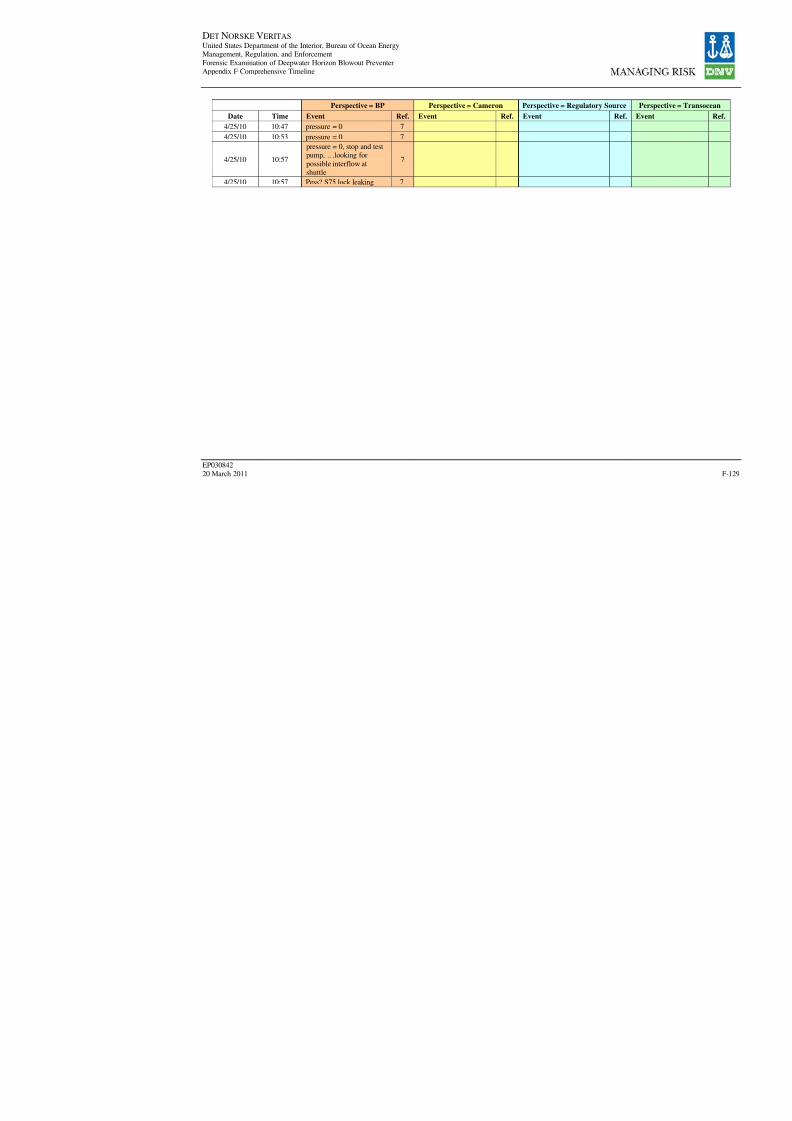
8/7/2019 DNV BOP report - Vol 2 (2)
http://slidepdf.com/reader/full/dnv-bop-report-vol-2-2 294/350
DET NORSKE VERITAS United States Department of the Interior, Bureau of Ocean EnergyManagement, Regulation, and Enforcement
Forensic Examination of Deepwater Horizon Blowout PreventerAppendix F Comprehensive Timeline
EP030842
20 March 2011
Perspective = BP Perspective = Cameron Perspective = Regulatory Sour
Date Time Event Ref. Event Ref. Event R
4/25/10 10:47 pressure = 0 74/25/10 10:53 pressure = 0 7
4/25/10 10:57
pressure = 0, stop and testpump, …looking for
possible interflow atshuttle
7
4/25/10 10:57 Pess? S75 lock leaking 7
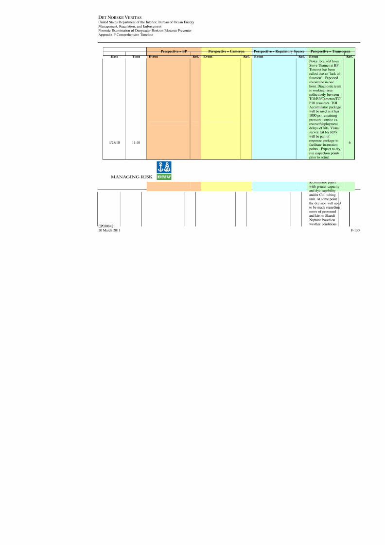
8/7/2019 DNV BOP report - Vol 2 (2)
http://slidepdf.com/reader/full/dnv-bop-report-vol-2-2 295/350
DET NORSKE VERITAS United States Department of the Interior, Bureau of Ocean EnergyManagement, Regulation, and Enforcement
Forensic Examination of Deepwater Horizon Blowout PreventerAppendix F Comprehensive Timeline
EP030842
20 March 2011
Perspective = BP Perspective = Cameron Perspective = Regulatory Sour
Date Time Event Ref. Event Ref. Event R
4/25/10 11:40

8/7/2019 DNV BOP report - Vol 2 (2)
http://slidepdf.com/reader/full/dnv-bop-report-vol-2-2 296/350
DET NORSKE VERITAS United States Department of the Interior, Bureau of Ocean EnergyManagement, Regulation, and Enforcement
Forensic Examination of Deepwater Horizon Blowout PreventerAppendix F Comprehensive Timeline
EP030842
20 March 2011
Perspective = BP Perspective = Cameron Perspective = Regulatory Sour
Date Time Event Ref. Event Ref. Event R
4/25/10 13:30
4/25/10 13:50
4/25/10 14:15 sub Sea on plume 7

8/7/2019 DNV BOP report - Vol 2 (2)
http://slidepdf.com/reader/full/dnv-bop-report-vol-2-2 297/350
DET NORSKE VERITAS United States Department of the Interior, Bureau of Ocean EnergyManagement, Regulation, and Enforcement
Forensic Examination of Deepwater Horizon Blowout PreventerAppendix F Comprehensive Timeline
EP030842
20 March 2011
Perspective = BP Perspective = Cameron Perspective = Regulatory Sour
Date Time Event Ref. Event Ref. Event R
4/25/10 14:15Make a dry run for POI's.Trace the plumbing andinspect shuttle valves
7
4/25/10 14:15
ST locks were removed,plumbing may have been
changed by Transocean7
4/25/10 15:50
"the S75 system wasmodified and ? Of monthsago" "this changed a ? Hotstab panel capability to a
combined close/S75function" "This may be a
leak path … because it iscommon to the VBR/shearram function"
7
[Date/Time Not Given]"the lower stack ROV
panel was reconfiguredwith the hot-stab
configurations"
1
4/25/10 19:30
4/25/10 20:15
plugging stab into piperams with sequence: 1)
high pressure shear panelvalve 2) ST Lock valves
7
4/25/10 20:45
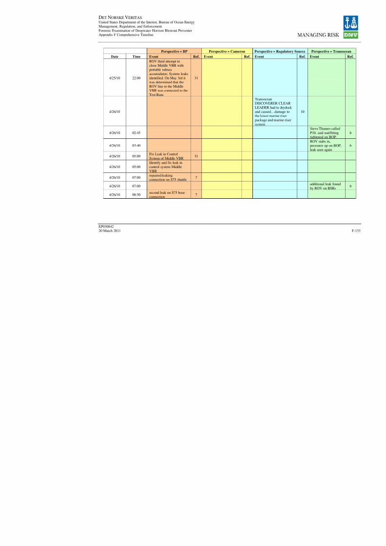
8/7/2019 DNV BOP report - Vol 2 (2)
http://slidepdf.com/reader/full/dnv-bop-report-vol-2-2 298/350
DET NORSKE VERITAS United States Department of the Interior, Bureau of Ocean EnergyManagement, Regulation, and Enforcement
Forensic Examination of Deepwater Horizon Blowout PreventerAppendix F Comprehensive Timeline
EP030842
20 March 2011
Perspective = BP Perspective = Cameron Perspective = Regulatory Sour
Date Time Event Ref. Event Ref. Event R
4/25/10 22:00
ROV third attempt toclose Middle VBR withportable subsea
accumulator; System leaksidentified. On May 3rd itwas determined that theROV line to the MiddleVBR was connected to the
Test Ram
31
4/26/10
TransoceanDISCOVERER CLEAR
LEADER had to drydock and caused…damage tothe lower marine riserpackage and marine riser
system
1
4/26/10 02:45
4/26/10 03:40
4/26/10 05:00Fix Leak in Control
System of Middle VBR31
4/26/10 05:00
Identify and fix leak in
control system MiddleVBR
4/26/10 07:00repaired leakingconnection on S75 shuttle
7
4/26/10 07:00
4/26/10 08:50second leak on S75 hoseconnection
7
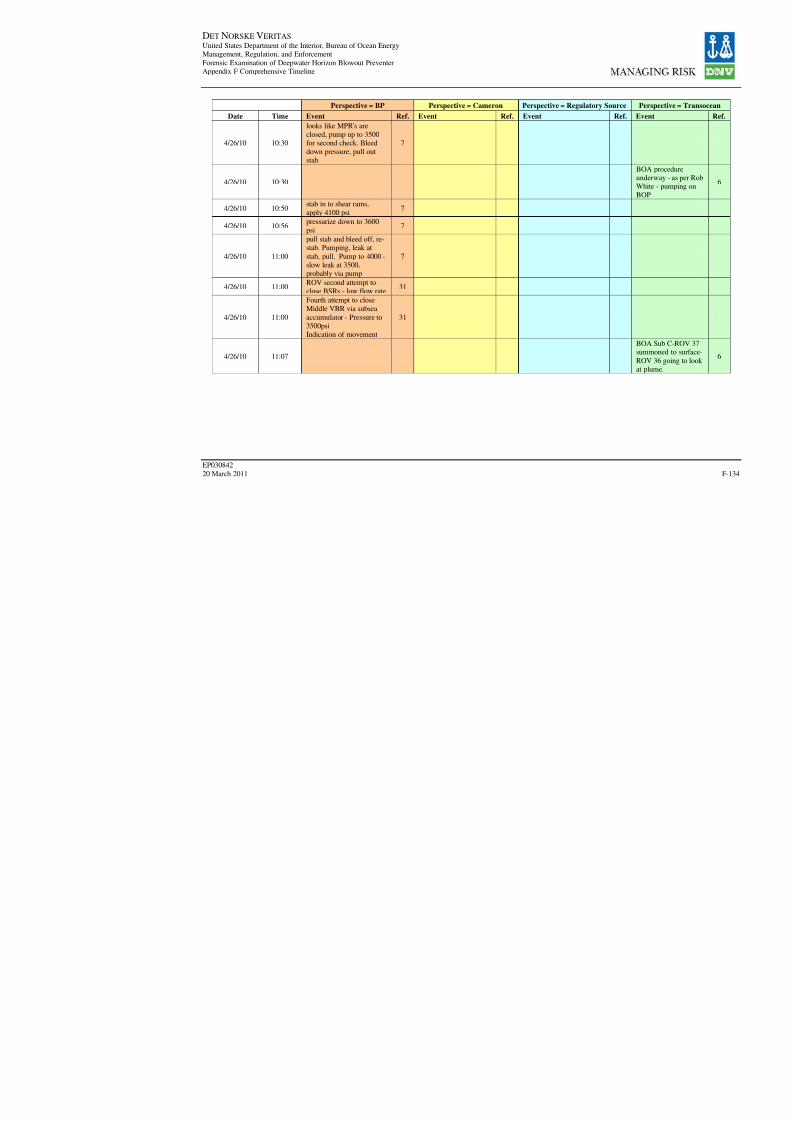
8/7/2019 DNV BOP report - Vol 2 (2)
http://slidepdf.com/reader/full/dnv-bop-report-vol-2-2 299/350
DET NORSKE VERITAS United States Department of the Interior, Bureau of Ocean EnergyManagement, Regulation, and Enforcement
Forensic Examination of Deepwater Horizon Blowout PreventerAppendix F Comprehensive Timeline
EP030842
20 March 2011
Perspective = BP Perspective = Cameron Perspective = Regulatory Sour
Date Time Event Ref. Event Ref. Event R
4/26/10 10:30
looks like MPR's areclosed, pump up to 3500for second check. Bleed
down pressure, pull outstab
7
4/26/10 10:30
4/26/10 10:50stab in to shear rams,
apply 4100 psi7
4/26/10 10:56pressurize down to 3600psi
7
4/26/10 11:00
pull stab and bleed off, re-stab. Pumping, leak at
stab, pull. Pump to 4000 -slow leak at 3500,probably via pump
7
4/26/10 11:00ROV second attempt toclose BSRs - low flow rate
31
4/26/10 11:00
Fourth attempt to closeMiddle VBR via subsea
accumulator - Pressure to3500psiIndication of movement
31
4/26/10 11:07
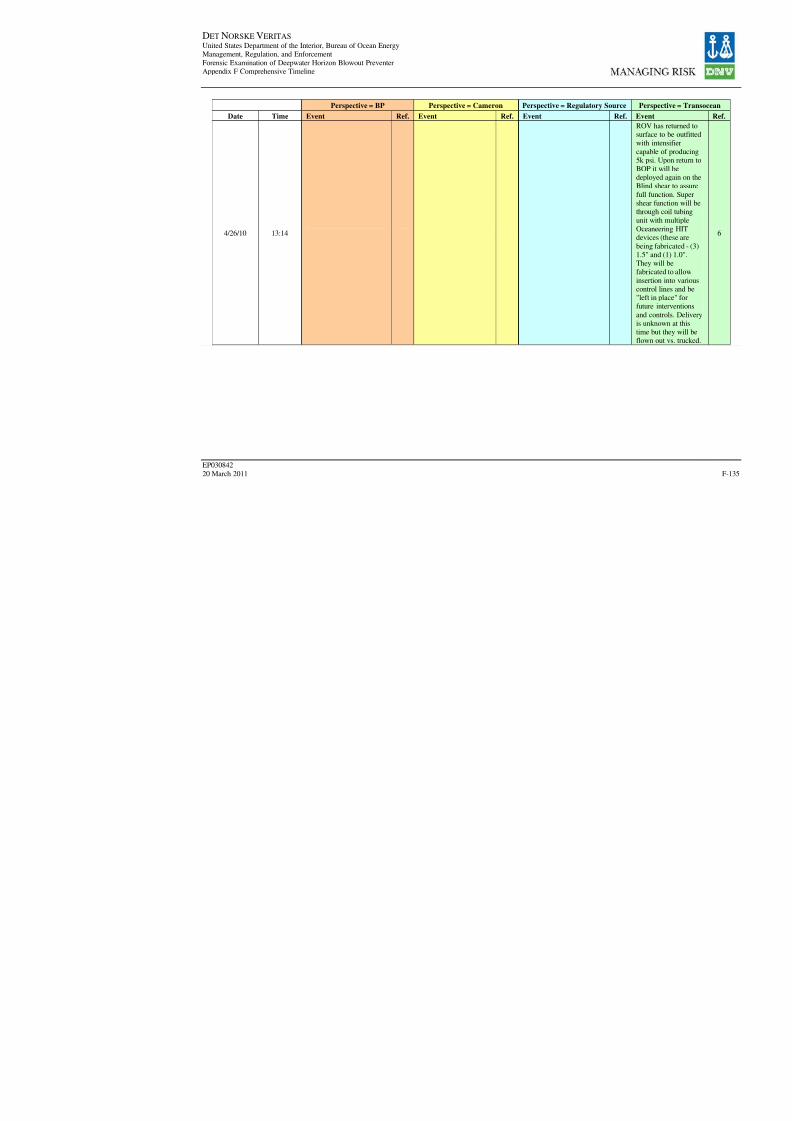
8/7/2019 DNV BOP report - Vol 2 (2)
http://slidepdf.com/reader/full/dnv-bop-report-vol-2-2 300/350
DET NORSKE VERITAS United States Department of the Interior, Bureau of Ocean EnergyManagement, Regulation, and Enforcement
Forensic Examination of Deepwater Horizon Blowout PreventerAppendix F Comprehensive Timeline
EP030842
20 March 2011
Perspective = BP Perspective = Cameron Perspective = Regulatory Sour
Date Time Event Ref. Event Ref. Event R
4/26/10 13:14

8/7/2019 DNV BOP report - Vol 2 (2)
http://slidepdf.com/reader/full/dnv-bop-report-vol-2-2 301/350
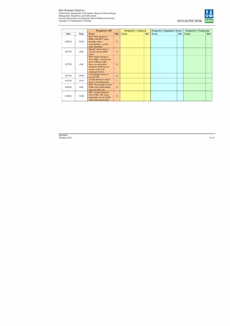
8/7/2019 DNV BOP report - Vol 2 (2)
http://slidepdf.com/reader/full/dnv-bop-report-vol-2-2 302/350
DET NORSKE VERITAS United States Department of the Interior, Bureau of Ocean EnergyManagement, Regulation, and Enforcement
Forensic Examination of Deepwater Horizon Blowout PreventerAppendix F Comprehensive Timeline
EP030842
20 March 2011
Perspective = BP Perspective = Cameron Perspective = Regulatory Sour
Date Time Event Ref. Event Ref. Event R
4/26/10 22:00
ROV third attempt toBSRs with ROV usingportable subsea
accumulators - systemleaks identified
31
4/27/10 0:00Identify and fix leak inControl system (BSRentry)
31
4/27/10 4:00
ROV fourth attempt toclose BSRs - pressurized
up to 5,000 psi eighttimes, no movement
identified. BSR had notsealed, as the wellcontinued to flow
31
4/27/10 10:00Cut hydraulic hoses toaccess CSR
41
4/27/10 15:45second attempt to attachhose to coil tubing unit
7
4/28/10 0:00
ROV first attempt to closeCSRs with coiled tubing
unit; low flow rate31
4/28/10 23:00
ROV second attempt toclose CSRs with wand;apparently moved shuttlevalve, but system leaks
31
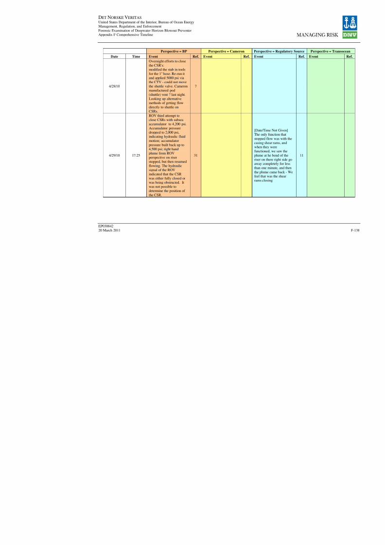
8/7/2019 DNV BOP report - Vol 2 (2)
http://slidepdf.com/reader/full/dnv-bop-report-vol-2-2 303/350
DET NORSKE VERITAS United States Department of the Interior, Bureau of Ocean EnergyManagement, Regulation, and Enforcement
Forensic Examination of Deepwater Horizon Blowout PreventerAppendix F Comprehensive Timeline
EP030842
20 March 2011
Perspective = BP Perspective = Cameron Perspective = Regulatory Sour
Date Time Event Ref. Event Ref. Event R
4/28/10
Overnight efforts to closethe CSR's:modified the stab in tools
for the 1" hose. Re-run itand applied 5000 psi viathe CTV - could not movethe shuttle valve. Cameronmanufactured pod
(shuttle) vent ? last night.Looking up alternativemethods of getting flow
directly to shuttle onCSRs.
7
4/29/10 17:25
ROV third attempt toclose CSRs with subsea
accumulator to 4,200 psi.Accumulator pressuredropped to 2,000 psi,indicating hydraulic fluid
motion; accumulatorpressure built back up to4,500 psi; right handplume from ROV
perspective on riserstopped, but then resumedflowing. The hydraulicsignal of the ROVindicated that the CSR
was either fully closed or
was being obstructed. Itwas not possible todetermine the position of
the CSR.
31
[Date/Time Not Given]The only function that
stopped flow was with thecasing shear rams, andwhen they werefunctioned, we saw the
plume at he bend of theriser on there right side goaway completely for lessthan one minute, and then
the plume came back - Wefeel that was the shearrams closing
1

8/7/2019 DNV BOP report - Vol 2 (2)
http://slidepdf.com/reader/full/dnv-bop-report-vol-2-2 304/350
DET NORSKE VERITAS United States Department of the Interior, Bureau of Ocean EnergyManagement, Regulation, and Enforcement
Forensic Examination of Deepwater Horizon Blowout PreventerAppendix F Comprehensive Timeline
EP030842
20 March 2011
Perspective = BP Perspective = Cameron Perspective = Regulatory Sour
Date Time Event Ref. Event Ref. Event R
4/29/10 21:30
ROV fifth attempt to closeBSRs - pressured up to5,500 psi twice. BSR may
have been activated byEDS, AMF, ROV(autoshear), or ROV hotstab. This was the finalattempt to close the BSR
before it was determinedon 10 May that the BSRwas closed and locked.
However, regardlesswhether this or previousaction had closed the BSR,
it had failed to seal in this
fully closed position.
31
4/30/10 6:00
Cut hose and attempt toclose Upper A via subseaaccumulator - System
leaks identified?
41
5/1/10 06:30
all ready to go on upper
annular. Observed leak onParker? Clamps, willretighten and try againwhile we fabricate a
clamshell type clamp.
7
5/1/10 12:00ROV found and fixedleaks in Upper Annularcircuit/control system
31
5/1/10 13:50
Theiren's log states: "Stab-in on the middle pipe ramsas being plumbed for thetest rams, not the middlepipe rams."
1
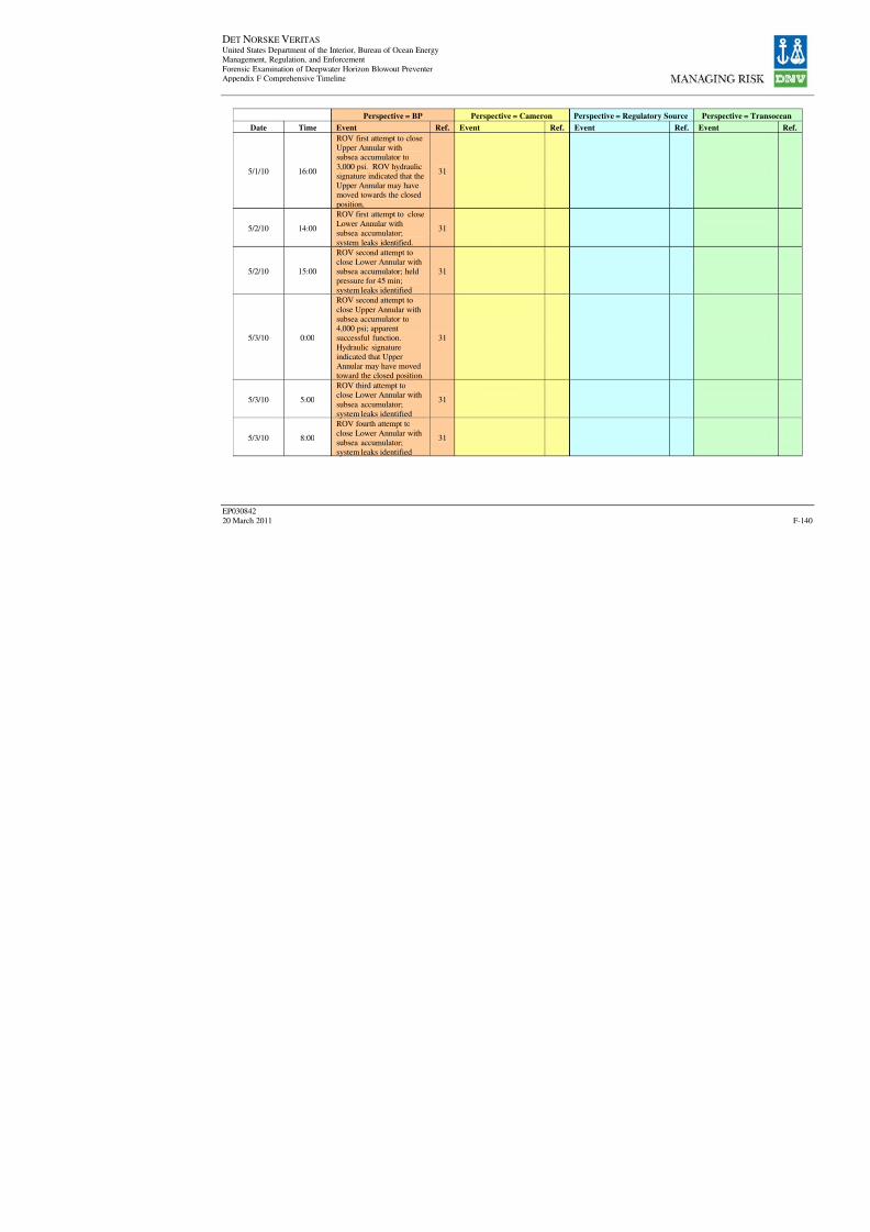
8/7/2019 DNV BOP report - Vol 2 (2)
http://slidepdf.com/reader/full/dnv-bop-report-vol-2-2 305/350
DET NORSKE VERITAS United States Department of the Interior, Bureau of Ocean EnergyManagement, Regulation, and Enforcement
Forensic Examination of Deepwater Horizon Blowout PreventerAppendix F Comprehensive Timeline
EP030842
20 March 2011
Perspective = BP Perspective = Cameron Perspective = Regulatory Sour
Date Time Event Ref. Event Ref. Event R
5/1/10 16:00
ROV first attempt to closeUpper Annular withsubsea accumulator to
3,000 psi. ROV hydraulicsignature indicated that theUpper Annular may havemoved towards the closedposition,
31
5/2/10 14:00
ROV first attempt to close
Lower Annular withsubsea accumulator;
system leaks identified.
31
5/2/10 15:00
ROV second attempt toclose Lower Annular withsubsea accumulator; heldpressure for 45 min;system leaks identified
31
5/3/10 0:00
ROV second attempt to
close Upper Annular withsubsea accumulator to4,000 psi; apparentsuccessful function.
Hydraulic signatureindicated that UpperAnnular may have movedtoward the closed position.
31
5/3/10 5:00
ROV third attempt toclose Lower Annular with
subsea accumulator;
system leaks identified
31
5/3/10 8:00
ROV fourth attempt to
close Lower Annular withsubsea accumulator;system leaks identified
31
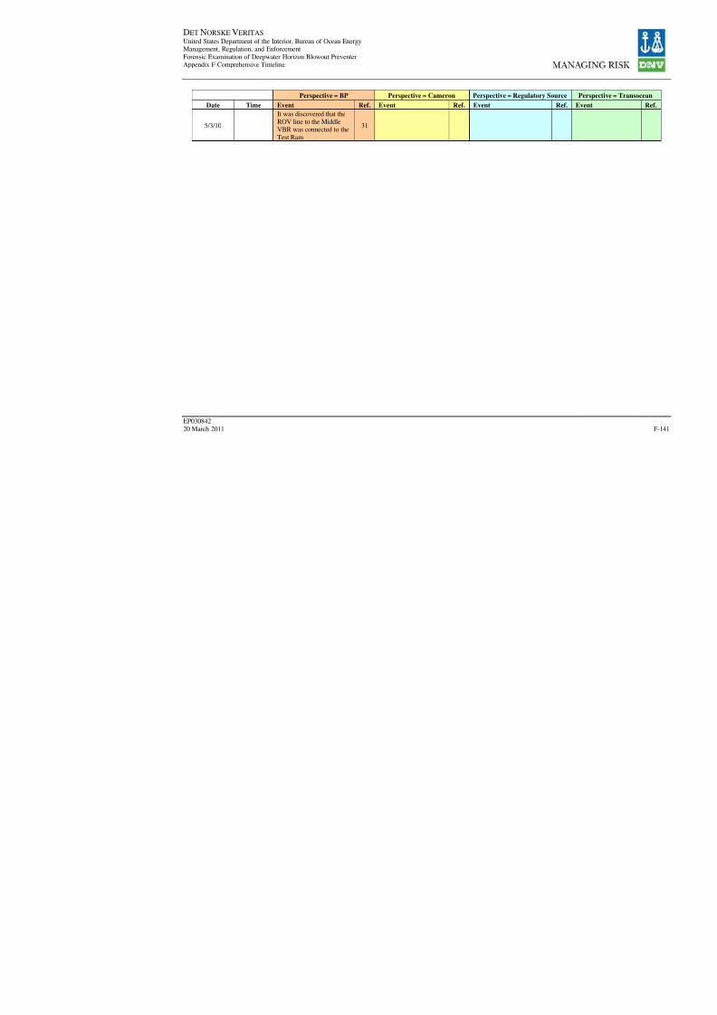
8/7/2019 DNV BOP report - Vol 2 (2)
http://slidepdf.com/reader/full/dnv-bop-report-vol-2-2 306/350
DET NORSKE VERITAS United States Department of the Interior, Bureau of Ocean EnergyManagement, Regulation, and Enforcement
Forensic Examination of Deepwater Horizon Blowout PreventerAppendix F Comprehensive Timeline
EP030842
20 March 2011
Perspective = BP Perspective = Cameron Perspective = Regulatory Sour
Date Time Event Ref. Event Ref. Event R
5/3/10
It was discovered that theROV line to the MiddleVBR was connected to the
Test Ram
31
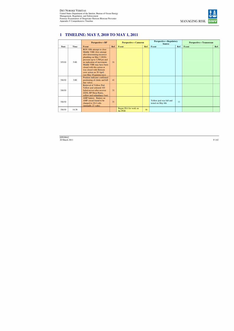
8/7/2019 DNV BOP report - Vol 2 (2)
http://slidepdf.com/reader/full/dnv-bop-report-vol-2-2 307/350
DET NORSKE VERITAS United States Department of the Interior, Bureau of Ocean EnergyManagement, Regulation, and Enforcement
Forensic Examination of Deepwater Horizon Blowout PreventerAppendix F Comprehensive Timeline
EP030842
20 March 2011
1 TIMELINE: MAY 5, 2010 TO MAY 1, 2011
Perspective = BP Perspective = CameronPerspective = Regulatory
Source
Date Time Event Ref. Event Ref. Event Ref.
5/5/10 5:00
ROV fifth attempt to closeMiddle VBR (first attemptafter determining incorrect
plumbing on May 3 2010);pressure up to 3,500 psi andno indication of movement.Middle VBR may have been
closed with this action orwas closed with Horizoncrew action on 20 April.
(see May 10 gamma rays)
31
5/6/10 3:00
Position indicator confirmed
positioning of choke and killline valves
41
5/6/10
Retrieval of Yellow Pod.Yellow pod solenoid 103
failed on test after recover(EDS, HP Shear Rams,yellow pod redundancy lost)
31
5/6/10
AMF battery. Battery onAMF circuit found to becharged to 18.4 volts
(normally 27 volts)
31Yellow pod was full andtested on May 6th
11
5/6/10 14:38Began JSA for work on
the POD
16

8/7/2019 DNV BOP report - Vol 2 (2)
http://slidepdf.com/reader/full/dnv-bop-report-vol-2-2 308/350
DET NORSKE VERITAS United States Department of the Interior, Bureau of Ocean EnergyManagement, Regulation, and Enforcement
Forensic Examination of Deepwater Horizon Blowout PreventerAppendix F Comprehensive Timeline
EP030842
20 March 2011
Perspective = BP Perspective = CameronPerspective = Regulatory
Source
Date Time Event Ref. Event Ref. Event Ref.
5/6/10 15:13
Tape off cut lines forsafety to prevent cutsfrom sharp edges due toROV demolition: (1) S1supply line, (2) function
#24 (this function islabeled blank on SK-122108-21-05), (3) function #49 (this is POD
select on SK-122108-21-05), (4) function was notlabeled - Hyd line willhave to be traced to
determine what this line
was used for.
16
5/6/10 15:18Removal of (2) unknownpilot line
16
5/6/10 15:20Removal of (3) function
#49 pilot line16
5/6/10 15:21Removal of (4) unknownpilot line
16
5/6/10 15:26
Removal of (1) S1. Thecode 62 flange wasunbolted and the
demolished portion of thesupply line was removed
16

8/7/2019 DNV BOP report - Vol 2 (2)
http://slidepdf.com/reader/full/dnv-bop-report-vol-2-2 309/350
DET NORSKE VERITAS United States Department of the Interior, Bureau of Ocean EnergyManagement, Regulation, and Enforcement
Forensic Examination of Deepwater Horizon Blowout PreventerAppendix F Comprehensive Timeline
EP030842
20 March 2011
Perspective = BP Perspective = CameronPerspective = Regulatory
Source
Date Time Event Ref. Event Ref. Event Ref.
5/6/10 15:37
Removal of flow meterassembly from POD andmoved to workbench.This was done to allowthe installation of the new
pre bent pipe work to beassembled to the supplyside of the flow meter. Inorder to complete this
step a section of pipework that was notdemolished had to beremoved [(5) this section
was on the supply side
and was code 62 by CVPunion that secures in tothe flow meter]
16
5/6/10 15:43
Dry fit up on hydraulic
supply adapter. (5) code62 by CVP union was
moved to lockbox.
16
5/6/10 15:52
Building of scaffolding to
allow removal of PBOFcables in the MUXsection
16
5/6/10 15:57
Removal of Roughneck connector (6). At the
same time adjustmentswere made to the newsupply adaptor at theworkbench.
16
5/6/10 15:58(6) Roughneck connectorwas moved to lockbox.
16
5/6/10 16:02
Qty. 2 o-rings were found
to be in the connector forthe face seal
16

8/7/2019 DNV BOP report - Vol 2 (2)
http://slidepdf.com/reader/full/dnv-bop-report-vol-2-2 310/350
DET NORSKE VERITAS United States Department of the Interior, Bureau of Ocean EnergyManagement, Regulation, and Enforcement
Forensic Examination of Deepwater Horizon Blowout PreventerAppendix F Comprehensive Timeline
EP030842
20 March 2011
Perspective = BP Perspective = CameronPerspective = Regulatory
Source
Date Time Event Ref. Event Ref. Event Ref.
5/6/10 16:16
Install 1" hydraulic supplyadapter - Note: it wasnoticed at this time thatthe radial seal in the flowmeter was missing.
16
5/6/10 16:26
Drill hole to mount a 1"
ball valve for ROVoperations while subsea
16
5/6/10 16:28
Install radial o-ring forflow meter (7) and faceseal for flow meter.
Installed made upelectrical connector forflow meter.
16
5/6/10 16:50
Found 2 Stinger sealblown - unknown
functions at this time (8) stinger seal, pn 11687-01moved to lock box. At
this time Erwin enteredthe Mod section in orderto obtain the functionnumber that is stenciled
on top of the riser stingerassy. Was able todetermine that thefunction was directly
behind #41 at 1/2" port.Machine detail x-200030-01
16
5/6/10 16:57(9) stinger seal removedand moved to lockbox
16
5/6/10 17:01Installed 2 new stingerseals
16

8/7/2019 DNV BOP report - Vol 2 (2)
http://slidepdf.com/reader/full/dnv-bop-report-vol-2-2 311/350

8/7/2019 DNV BOP report - Vol 2 (2)
http://slidepdf.com/reader/full/dnv-bop-report-vol-2-2 312/350
DET NORSKE VERITAS United States Department of the Interior, Bureau of Ocean EnergyManagement, Regulation, and Enforcement
Forensic Examination of Deepwater Horizon Blowout PreventerAppendix F Comprehensive Timeline
EP030842
20 March 2011
Perspective = BP Perspective = CameronPerspective = Regulatory
Source
Date Time Event Ref. Event Ref. Event Ref.
5/6/10 19:31
Installed pilot 1/4" line toROV valve (pilot supplyto solenoid) STM II leftside and STM I right side
16
5/6/10 19:47
connect new PBOF cableon STM PN:2185879-22-
0516
5/6/10 19:53Connect new PBOF cableon STM II pn:2185879-22-05
16
5/6/10 19:55Connect PBOF cablefrom STM I to SEM
16
5/6/10 19:57Connect PBOF cablefrom SM II to SEM
16
5/6/10 20:15
Pre-job safety meetingwith Cameron, TOI, BPto complete JSA forPETU testing
16
5/6/10 20:35
Power up PETU connect
to SEM. Verified .ini filewas RBS8D. Read back on the yellow POD showsthe SEM is BLUE A and
BLUE B. It should benoted that the Distributioncabinets on surfacedesignate which POD is
BLUE and which POD is
yellow
16
5/6/10 20:43
Deadman system wasarmed via PETU. Readback from the STMs weregood, no faults were
noted.
16
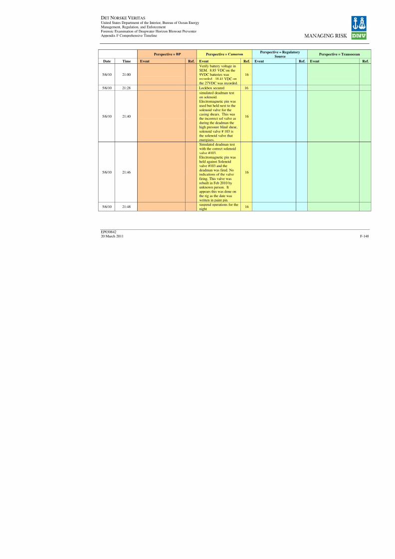
8/7/2019 DNV BOP report - Vol 2 (2)
http://slidepdf.com/reader/full/dnv-bop-report-vol-2-2 313/350
DET NORSKE VERITAS United States Department of the Interior, Bureau of Ocean EnergyManagement, Regulation, and Enforcement
Forensic Examination of Deepwater Horizon Blowout PreventerAppendix F Comprehensive Timeline
EP030842
20 March 2011
Perspective = BP Perspective = CameronPerspective = Regulatory
Source
Date Time Event Ref. Event Ref. Event Ref.
5/6/10 21:00
Verify battery voltage inSEM. 8.85 VDC on the9VDC batteries wasrecorded. 18.41 VDC onthe 27VDC was recorded.
16
5/6/10 21:28 Lockbox secured 16
5/6/10 21:40
simulated deadman teston solenoid.Electromagnetic pin wasused but held next to the
solenoid valve for thecasing shears. This wasthe incorrect sol valve asduring the deadman the
high pressure blind shear,solenoid valve # 103 isthe solenoid valve thatenergizes.
16
5/6/10 21:46
Simulated deadman testwith the correct solenoid
valve #103.Electromagnetic pin was
held against Solenoidvalve #103 and thedeadman was fired. Noindications of the valve
firing. This valve wasrebuilt in Feb 2010 by
unknown person. Itappears this was done on
the rig as the date waswritten in paint pin.
16
5/6/10 21:48suspend operations for thenight
16

8/7/2019 DNV BOP report - Vol 2 (2)
http://slidepdf.com/reader/full/dnv-bop-report-vol-2-2 314/350
DET NORSKE VERITAS United States Department of the Interior, Bureau of Ocean EnergyManagement, Regulation, and Enforcement
Forensic Examination of Deepwater Horizon Blowout PreventerAppendix F Comprehensive Timeline
EP030842
20 March 2011
Perspective = BP Perspective = CameronPerspective = Regulatory
Source
Date Time Event Ref. Event Ref. Event Ref.
5/7/10 09:00
Discussion on layout of equipment for running thePOD subsea. Oceaneeringis providing a LARS(Landing and Recovery
System) to run the hotlineand MUX cable on
16
5/7/10 09:40
Cut and terminated 1"hose for S1 to Ball valvemounted on the MUX
section for solenoidsupply. Waiting onpressure test from rig
16
5/7/10 10:00
began terminating MUX
cable to Jbox on the reel 16
5/7/10 11:30
discussions held with
service departmentregarding which functionsto use to operate the mini-
connectors that will latchonto the choke and killlines. The plane will beto use gasket release for
the LMRP and wellheadconnectors along with thesolenoid valve for PODselect and one of the
unknown solenoid valvesthat was going to the CVP(conduit valve package).Qty 4 hoses with be
connected directly toPOD via JIC fitting.
16

8/7/2019 DNV BOP report - Vol 2 (2)
http://slidepdf.com/reader/full/dnv-bop-report-vol-2-2 315/350
DET NORSKE VERITAS United States Department of the Interior, Bureau of Ocean EnergyManagement, Regulation, and Enforcement
Forensic Examination of Deepwater Horizon Blowout PreventerAppendix F Comprehensive Timeline
EP030842
20 March 2011
Perspective = BP Perspective = CameronPerspective = Regulatory
Source
Date Time Event Ref. Event Ref. Event Ref.
5/7/10 12:37
Began JSA for sealtesting of PBOF cables.Downloaded seal testprocedure to perform test(x-200136-05)
16
5/7/10 13:30
Jumper hose from ball
valve to supply completedtest and installed
16
5/7/10 14:30
fluid kit arrived on deck.Fluid testing underway.Note: the HPU skid does
not have a circulationpump to circulate thefluid in the tank. First
fluid sample from HPIskid was NAS Class 12.
(this was taken from thedischarge hose from the
accumulators). Secondfluid sample taken fromTank. Testing in progress.
16
5/7/10 15:12
PBOF cable from SEM toSTM II began and ended
at 3:22. Test was goodper x-200136-05. Noteboth ends of the PBOFwere tested at the same
time.
16
5/7/10 15:30
Discussion regarding by
passing the tank on theskid and pull straightfrom the totes if NASclass was not acceptable
from the tank.
16
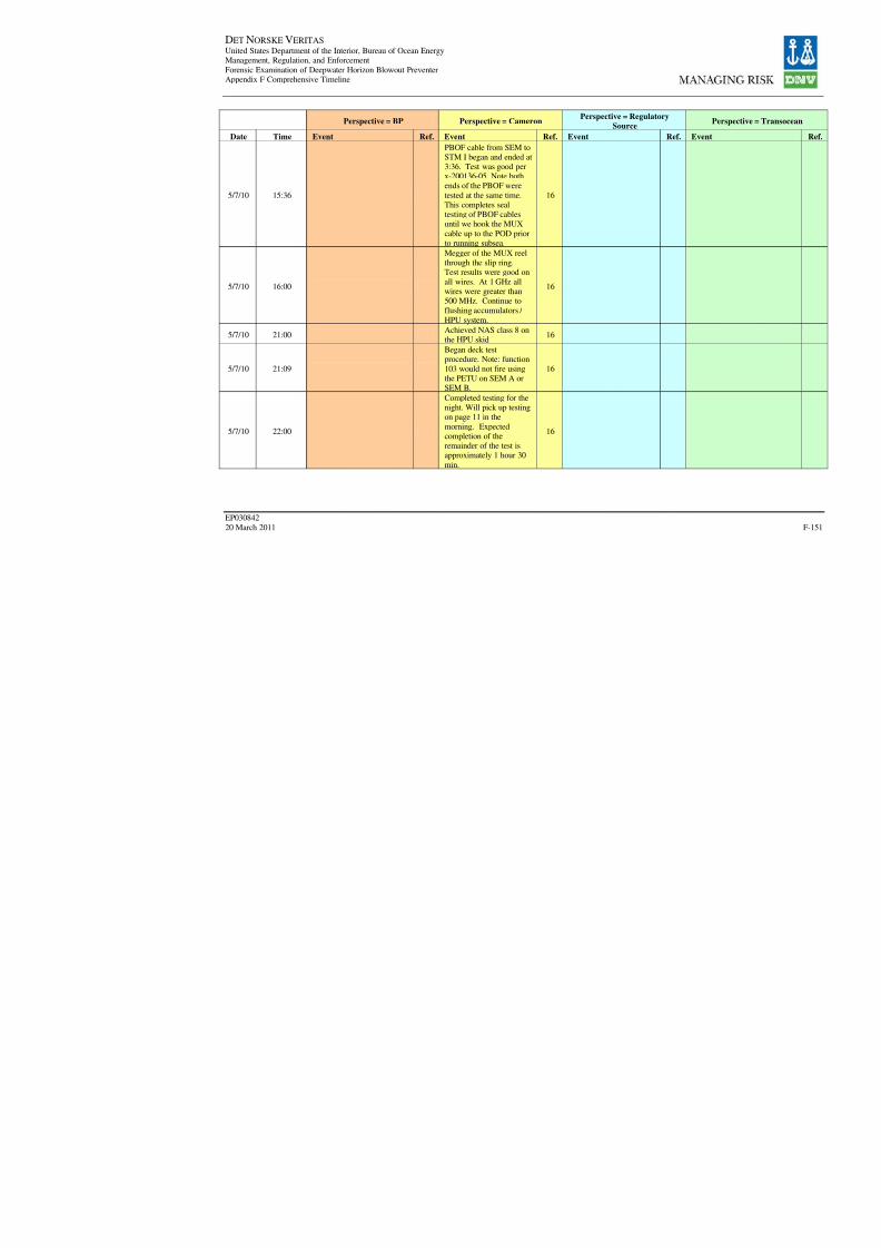
8/7/2019 DNV BOP report - Vol 2 (2)
http://slidepdf.com/reader/full/dnv-bop-report-vol-2-2 316/350
DET NORSKE VERITAS United States Department of the Interior, Bureau of Ocean EnergyManagement, Regulation, and Enforcement
Forensic Examination of Deepwater Horizon Blowout PreventerAppendix F Comprehensive Timeline
EP030842
20 March 2011
Perspective = BP Perspective = CameronPerspective = Regulatory
Source
Date Time Event Ref. Event Ref. Event Ref.
5/7/10 15:36
PBOF cable from SEM toSTM I began and ended at3:36. Test was good perx-200136-05. Note bothends of the PBOF were
tested at the same time.This completes sealtesting of PBOF cablesuntil we hook the MUX
cable up to the POD priorto running subsea.
16
5/7/10 16:00
Megger of the MUX reelthrough the slip ring.Test results were good on
all wires. At 1 GHz allwires were greater than500 MHz. Continue toflushing accumulators /
HPU system.
16
5/7/10 21:00Achieved NAS class 8 onthe HPU skid
16
5/7/10 21:09
Began deck testprocedure. Note: function
103 would not fire usingthe PETU on SEM A orSEM B.
16
5/7/10 22:00
Completed testing for thenight. Will pick up testingon page 11 in the
morning. Expectedcompletion of theremainder of the test isapproximately 1 hour 30
min.
16
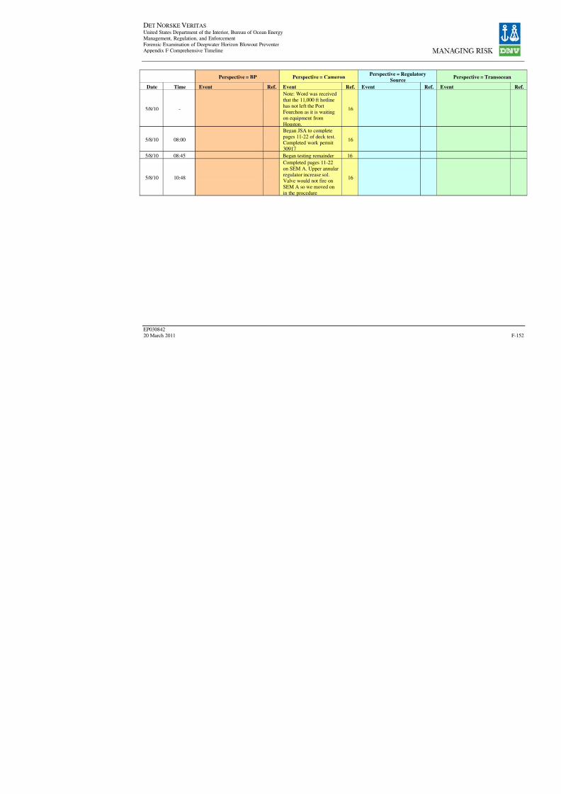
8/7/2019 DNV BOP report - Vol 2 (2)
http://slidepdf.com/reader/full/dnv-bop-report-vol-2-2 317/350
DET NORSKE VERITAS United States Department of the Interior, Bureau of Ocean EnergyManagement, Regulation, and Enforcement
Forensic Examination of Deepwater Horizon Blowout PreventerAppendix F Comprehensive Timeline
EP030842
20 March 2011
Perspective = BP Perspective = CameronPerspective = Regulatory
Source
Date Time Event Ref. Event Ref. Event Ref.
5/8/10 -
Note: Word was receivedthat the 11,000 ft hotlinehas not left the PortFourchon as it is waitingon equipment from
Houston.
16
5/8/10 08:00
Began JSA to completepages 11-22 of deck test.Completed work permit30917
16
5/8/10 08:45 Began testing remainder 16
5/8/10 10:48
Completed pages 11-22
on SEM A. Upper annularregulator increase sol.
Valve would not fire onSEM A so we moved on
in the procedure
16
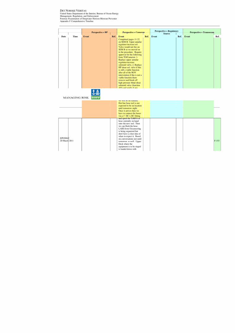
8/7/2019 DNV BOP report - Vol 2 (2)
http://slidepdf.com/reader/full/dnv-bop-report-vol-2-2 318/350
DET NORSKE VERITAS United States Department of the Interior, Bureau of Ocean EnergyManagement, Regulation, and Enforcement
Forensic Examination of Deepwater Horizon Blowout PreventerAppendix F Comprehensive Timeline
EP030842
20 March 2011
Perspective = BP Perspective = CameronPerspective = Regulatory
Source
Date Time Event Ref. Event Ref. Event Ref.
5/8/10 11:22
Completed pages 11-22on SEM B. Upper annularregulator increase sol.Valve would not fire onSEM B so we moved on
in the procedure. Requireapproval for the followingfrom TO/Cameron: 1.Replace upper annular
regulator increasesolenoid valve, 2. ReplaceHP shear sol. valve if thisis still a viable function
after all of the ROV
intervention if this is not aviable function themremove and blank off
high pressure blind shearsolenoid valve (function
103) and verify if anyadditional testing isrequired on the deadmancircuit. Note: Once these
two items are completedwe will be on standby.Hot line hose reel is notexpected to be on location
until tomorrow night.Once it arrives then we
have to connect the hosesvia a 1" JIC x JIC fitting
and spool the 5,000 ft of hose currently on handonto the new reel. Thenwe can flush the hose.
LARS from Oceaneeringis being organized butdon't have a clear idea of when to expect it. Based
on conversations not untiltomorrow as well. UpperDeck where the
equipment is to be stagedis loaded down with
16
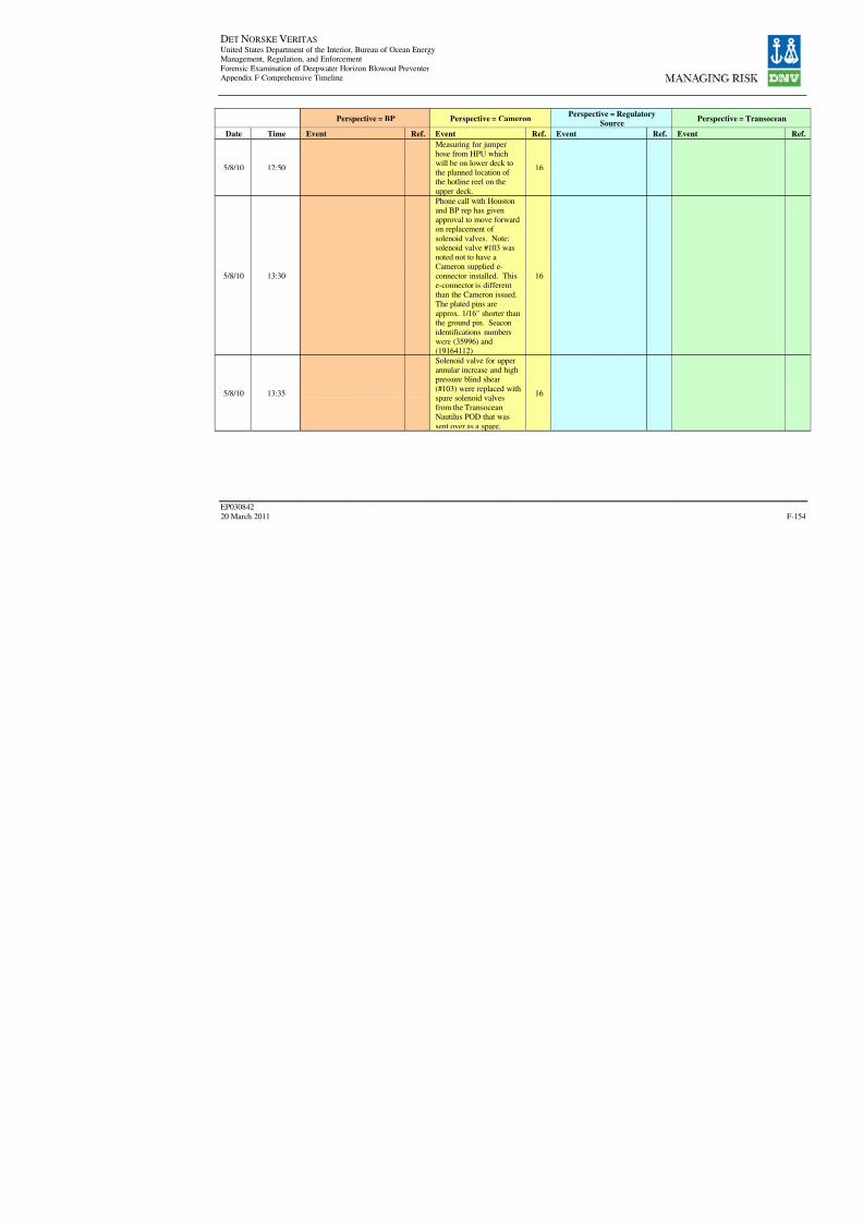
8/7/2019 DNV BOP report - Vol 2 (2)
http://slidepdf.com/reader/full/dnv-bop-report-vol-2-2 319/350
DET NORSKE VERITAS United States Department of the Interior, Bureau of Ocean EnergyManagement, Regulation, and Enforcement
Forensic Examination of Deepwater Horizon Blowout PreventerAppendix F Comprehensive Timeline
EP030842
20 March 2011
Perspective = BP Perspective = CameronPerspective = Regulatory
Source
Date Time Event Ref. Event Ref. Event Ref.
5/8/10 12:50
Measuring for jumperhose from HPU whichwill be on lower deck tothe planned location of the hotline reel on the
upper deck.
16
5/8/10 13:30
Phone call with Houstonand BP rep has givenapproval to move forwardon replacement of
solenoid valves. Note:solenoid valve #103 wasnoted not to have aCameron supplied e-
connector installed. Thise-connector is differentthan the Cameron issued.The plated pins are
approx. 1/16" shorter thanthe ground pin. Seacon
identifications numberswere (35996) and(19164112)
16
5/8/10 13:35
Solenoid valve for upperannular increase and highpressure blind shear
(#103) were replaced withspare solenoid valvesfrom the TransoceanNautilus POD that was
sent over as a spare.
16
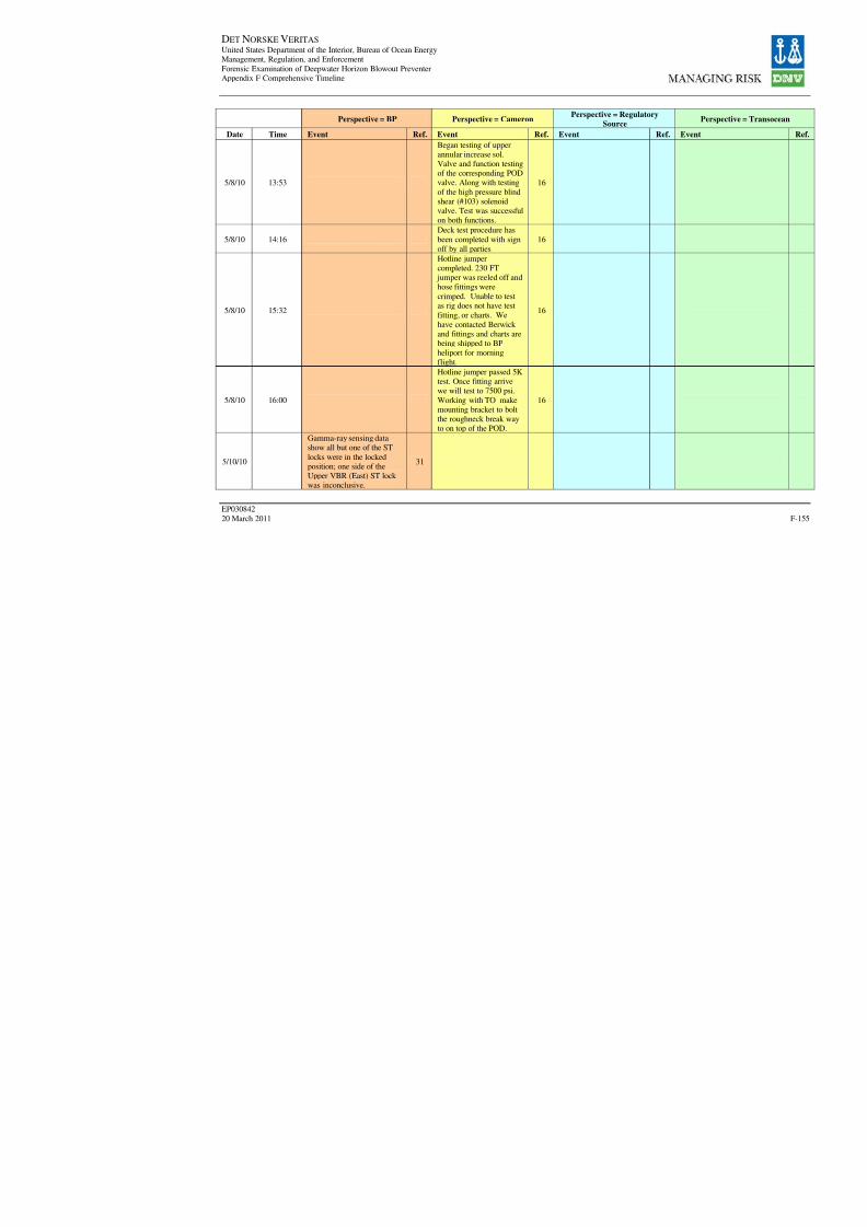
8/7/2019 DNV BOP report - Vol 2 (2)
http://slidepdf.com/reader/full/dnv-bop-report-vol-2-2 320/350
DET NORSKE VERITAS United States Department of the Interior, Bureau of Ocean EnergyManagement, Regulation, and Enforcement
Forensic Examination of Deepwater Horizon Blowout PreventerAppendix F Comprehensive Timeline
EP030842
20 March 2011
Perspective = BP Perspective = CameronPerspective = Regulatory
Source
Date Time Event Ref. Event Ref. Event Ref.
5/8/10 13:53
Began testing of upperannular increase sol.Valve and function testingof the corresponding PODvalve. Along with testing
of the high pressure blindshear (#103) solenoidvalve. Test was successfulon both functions.
16
5/8/10 14:16
Deck test procedure has
been completed with signoff by all parties
16
5/8/10 15:32
Hotline jumpercompleted. 230 FT
jumper was reeled off andhose fittings were
crimped. Unable to testas rig does not have test
fitting, or charts. Wehave contacted Berwick and fittings and charts arebeing shipped to BP
heliport for morningflight.
16
5/8/10 16:00
Hotline jumper passed 5Ktest. Once fitting arrivewe will test to 7500 psi.
Working with TO makemounting bracket to boltthe roughneck break wayto on top of the POD.
16
5/10/10
Gamma-ray sensing datashow all but one of the ST
locks were in the lockedposition; one side of theUpper VBR (East) ST lock was inconclusive.
31

8/7/2019 DNV BOP report - Vol 2 (2)
http://slidepdf.com/reader/full/dnv-bop-report-vol-2-2 321/350
DET NORSKE VERITAS United States Department of the Interior, Bureau of Ocean EnergyManagement, Regulation, and Enforcement
Forensic Examination of Deepwater Horizon Blowout PreventerAppendix F Comprehensive Timeline
EP030842
20 March 2011
Perspective = BP Perspective = CameronPerspective = Regulatory
Source
Date Time Event Ref. Event Ref. Event Ref.
5/10/10
AMF Test. After changingsolenoid 103, AMFsequence worked usingbattery that had only 18.4 V(AMF only needs one of 103
or 66)
31
5/13/10 16:00
ROV survey of ST locksusing gamma ray sensingconfirmed one ram of UpperVBR confirmed closed;
other ram ST lock inconclusive.
31
5/20/10
"…remotely operatedvehicle (ROV) intervention
activities to close the BOPwere ceased."
19
6/29/10 15:20
Rov Operators functioningtesting Rov Units with cuttermachine, unload the Pod
receptacles covers from thework boat, attempted tounload the shackle assemblyfor the work boat,
unsuccessful. The Shackleassembly consisted of 1- 10"sling, and one 55 ton Rovfriendly shackle.
3

8/7/2019 DNV BOP report - Vol 2 (2)
http://slidepdf.com/reader/full/dnv-bop-report-vol-2-2 322/350
DET NORSKE VERITAS United States Department of the Interior, Bureau of Ocean EnergyManagement, Regulation, and Enforcement
Forensic Examination of Deepwater Horizon Blowout PreventerAppendix F Comprehensive Timeline
EP030842
20 March 2011
Perspective = BP Perspective = CameronPerspective = Regulatory
Source
Date Time Event Ref. Event Ref. Event Ref.
6/29/10 18:00
Meeting with SubseaWells team. Decision isto continue to moveforward with recoverypending several variables:
weather permitting seas,wind, etc - the enterprisecan hold a heading of 120deg +/- 20 deg - we will
not stop well test flare. If we have to reduce thewell flow or shut it in weneed the permission of the
Unified command and the
white house - we can landthe POD on the Enterprisewith them still stuck on
Olympic Challenger.They must also agree that
we can pull the pod withthem on the OlympicChallenger. The coastguard official says he has
no problem with pullingor landing the POD ondeck if the issue iscustody of the equipment
as long as all partiesagree. We will secure the
area where the equipmentis landed and wait until all
parties are present for thetesting.
17

8/7/2019 DNV BOP report - Vol 2 (2)
http://slidepdf.com/reader/full/dnv-bop-report-vol-2-2 323/350
DET NORSKE VERITAS United States Department of the Interior, Bureau of Ocean EnergyManagement, Regulation, and Enforcement
Forensic Examination of Deepwater Horizon Blowout PreventerAppendix F Comprehensive Timeline
EP030842
20 March 2011
Perspective = BP Perspective = CameronPerspective = Regulatory
Source
Date Time Event Ref. Event Ref. Event Ref.
6/29/10 15:10
Prepare to run ROV to cutconnection from LMRP toBlue pod (approximately3 hour operation onceROV starts the actual
cutting). TO onboard theOlympic Challengerdirecting ROV. Theweather is deteriorating as
a result of TS Alex.Currently blue podrecovery is 3rd priority. Adecision will be made at
18:00 to determine if the
operation will continue. Itis decided that it will beterminated the next
possible window,according to weather
forecast, will be 7/2/10 or7/3/10. This is a looseestimate as there willprobably be other
operations with higherpriority at that time also.Note: Cameron personnelthat was present for
recovery of Yellow PODstated that only one of the
coils of the solenoid #3upper annular pilot supply
increase was defective.
17
6/30/10 09:00
Rov UHD 30 making cut on
the 1.22 OD Mux cable (electronic cable) cutcompleted @ 09:20
3

8/7/2019 DNV BOP report - Vol 2 (2)
http://slidepdf.com/reader/full/dnv-bop-report-vol-2-2 324/350
DET NORSKE VERITAS United States Department of the Interior, Bureau of Ocean EnergyManagement, Regulation, and Enforcement
Forensic Examination of Deepwater Horizon Blowout PreventerAppendix F Comprehensive Timeline
EP030842
20 March 2011
Perspective = BP Perspective = CameronPerspective = Regulatory
Source
Date Time Event Ref. Event Ref. Event Ref.
6/30/10 06:00
The ROV operations onthe Olympic Challengerwere delayed last nightuntil this morning. Thecutting of the electrical
and hydraulic connectionswill start at 6:30. Uponcompletion the decisionwill be made on whether
to run drill pipe forrecovery of the blue pod.The seas are deterioratingso likelihood of retrieval
is low for the next 24-48
hours. We will keepmonitoring weather anddeploy the drill pipe and
retrieval rigging if conditions allow.
17

8/7/2019 DNV BOP report - Vol 2 (2)
http://slidepdf.com/reader/full/dnv-bop-report-vol-2-2 325/350
DET NORSKE VERITAS United States Department of the Interior, Bureau of Ocean EnergyManagement, Regulation, and Enforcement
Forensic Examination of Deepwater Horizon Blowout PreventerAppendix F Comprehensive Timeline
EP030842
20 March 2011
Perspective = BP Perspective = CameronPerspective = Regulatory
Source
Date Time Event Ref. Event Ref. Event Ref.
6/30/10 18:00
Olympic Challenger hascompleted the cuttingoperations on the podconnections. Weather isstill holding us from
pulling the blue pod.Looks like Friday wouldbe the earliest opportunityto continue. Pod recovery
is still 3rd priority behindproject work for bringingHelix on line andlightering operations for
the Enterprise. We are
still at the mercy of meeting perfectconditions concerning
heading, weather, andoperations. It has been
confirmed that we willnot receive permission toshut down oil collectionfor the purpose of blue
pod retrieval. This adds arealm of uncertainty tothe operation.
17

8/7/2019 DNV BOP report - Vol 2 (2)
http://slidepdf.com/reader/full/dnv-bop-report-vol-2-2 326/350
DET NORSKE VERITAS United States Department of the Interior, Bureau of Ocean EnergyManagement, Regulation, and Enforcement
Forensic Examination of Deepwater Horizon Blowout PreventerAppendix F Comprehensive Timeline
EP030842
20 March 2011
Perspective = BP Perspective = CameronPerspective = Regulatory
Source
Date Time Event Ref. Event Ref. Event Ref.
7/1/10 06:00
Olympic Challenger iscompleting preparationwork for pulling the bluepod (stringers). We arestill waiting on weather to
cooperate for the blue podretrieval operation tobegin. Friday is going tobe best opportunity. Pod
retrieval is still thirdpriority behind projectwork for the HelixProducer, and lightering
operations on the
Enterprise. If we cansafely transfer TOI back to the Enterprise we are
going to schedule ameeting later today to
discuss the operation,raise any concerns, andfinalize details. Meetingto include TOI, BP
investigation, BPoperations, and Cameron.
17

8/7/2019 DNV BOP report - Vol 2 (2)
http://slidepdf.com/reader/full/dnv-bop-report-vol-2-2 327/350
DET NORSKE VERITAS United States Department of the Interior, Bureau of Ocean EnergyManagement, Regulation, and Enforcement
Forensic Examination of Deepwater Horizon Blowout PreventerAppendix F Comprehensive Timeline
EP030842
20 March 2011
Perspective = BP Perspective = CameronPerspective = Regulatory
Source
Date Time Event Ref. Event Ref. Event Ref.
7/1/10 18:00
Olympic Challenger iscompleting preparationwork for pulling the bluepod (stingers). They arehaving trouble de-
energizing the stinger. Weare still waiting onweather to cooperate forthe blue pod retrieval
operation to begin. Fridayis going to be bestopportunity. Pod retrievalis still third priority
behind project work for
the Helix Producer, andlightering operations onthe Enterprise. If we can
safely transfer TOI back to the Enterprise we are
going to schedule ameeting later today todiscuss the operation,raise any concerns, and
finalize details. Meetingto include TOI, BPinvestigation, BPoperations, and Cameron.
17
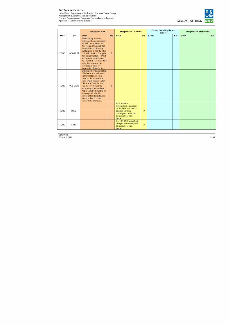
8/7/2019 DNV BOP report - Vol 2 (2)
http://slidepdf.com/reader/full/dnv-bop-report-vol-2-2 328/350
DET NORSKE VERITAS United States Department of the Interior, Bureau of Ocean EnergyManagement, Regulation, and Enforcement
Forensic Examination of Deepwater Horizon Blowout PreventerAppendix F Comprehensive Timeline
EP030842
20 March 2011
Perspective = BP Perspective = CameronPerspective = Regulatory
Source
Date Time Event Ref. Event Ref. Event Ref.
7/2/10 16:30-19:25
Held meeting with theEnterprise Team, Cameron,Bp and Tim Williams andRay Picard. Discussed thattown had stated that they
had function tested the BluePod with the OI3, EnterpriseRov notice that the 17 D hotstab was not hooked up to
the Blue Pod. Rov from OI3assist they where at theaccumulator pack, werequested to flush the line.
3
7/2/10 19:25-20:00
Enterprise Rov retrieved the
17 D hot in arm and waitedon the OI3 Rov to openvalue on the accumulatorpack. While waiting on the
OI3 Rov to flush the line.Had the Rov look at the
stack stingers, on the BluePod, it visually looked to bede-energized, visuallylooked at the stack stingers
on the yellow pod, andlooked to be energized.
3
7/2/10 00:00
ROV UHD 30troubleshoot electronicson the ROV unit, and re-position Olympic
challenger to assist theHelix Express withjumper.
17
7/2/10 01:57
Rove UHD 30 going back to depth and assisting the
Helix Express withjumper.
17

8/7/2019 DNV BOP report - Vol 2 (2)
http://slidepdf.com/reader/full/dnv-bop-report-vol-2-2 329/350
DET NORSKE VERITAS United States Department of the Interior, Bureau of Ocean EnergyManagement, Regulation, and Enforcement
Forensic Examination of Deepwater Horizon Blowout PreventerAppendix F Comprehensive Timeline
EP030842
20 March 2011
Perspective = BP Perspective = CameronPerspective = Regulatory
Source
Date Time Event Ref. Event Ref. Event Ref.
7/2/10 06:00
Continue assisting theHelix Express with thejumper hose. We spokewith the OI3, andconfirmed that they had
the 200" jumper with the17D hot stab
17

8/7/2019 DNV BOP report - Vol 2 (2)
http://slidepdf.com/reader/full/dnv-bop-report-vol-2-2 330/350
DET NORSKE VERITAS United States Department of the Interior, Bureau of Ocean EnergyManagement, Regulation, and Enforcement
Forensic Examination of Deepwater Horizon Blowout PreventerAppendix F Comprehensive Timeline
EP030842
20 March 2011
Perspective = BP Perspective = CameronPerspective = Regulatory
Source
Date Time Event Ref. Event Ref. Event Ref.
7/2/10 06:00
Olympic Challenger iscompleting preparationwork for pulling the bluepod (stingers). They arehaving trouble de-
energizing the stinger.ROV was reprioritizedlast night to work on theHelix Producer manifold
work so no attemps weremade to de-energize andretract the stingers. If theycan get the BOP stinger to
work we will run drill
pipe so we are readyshould a situation arisewere the heading of the
ship can be changed to120 deg +/- 20 deg and
secure the pod. The windis currently holding us ataround 190 deg. We aremarried to the flare so the
only 2 possibilities of getting a window are awind shift or an outsidereason to shut the well in.
Both scenarios are up tochance. Pod retrieval is
still third priority behindproject work for the Helix
Producer and lighteringoperations on theenterprise. If we cansafely transfer TO back to
the Enterprise we aregoing to schedule ameeting to discuss theoperation, raise any
concerns, and finalizedetails. Meeting toinclude TOI, BP
investigation, BPoperations, and cameron.
17

8/7/2019 DNV BOP report - Vol 2 (2)
http://slidepdf.com/reader/full/dnv-bop-report-vol-2-2 331/350
DET NORSKE VERITAS United States Department of the Interior, Bureau of Ocean EnergyManagement, Regulation, and Enforcement
Forensic Examination of Deepwater Horizon Blowout PreventerAppendix F Comprehensive Timeline
EP030842
20 March 2011
Perspective = BP Perspective = CameronPerspective = Regulatory
Source
Date Time Event Ref. Event Ref. Event Ref.
7/2/10 16:30
Held meeting with theEnterprise Team,Cameron, BP, and TOI.Discussed that town hadstated that they had
function tested the bluepod with the OI3,Enterprise ROVE noticethat the 17D hot stab was
not hooked up to the bluepod. ROV from OI3 assistthey where at theaccumulator pack, we
requested to flush the line.
17
7/2/10 18:00
TOI have been transferredback to the Enterprise. Allprevious attempts havebeen inconclusive and
reported as leaking. It wasdetermined that they had
only put 2000 psi on thecircuit that is normallyoperated to 3000 psi. Weare jumping the
Enterprise port ROV tointervene and determinewhat is happening and putthe correct pressure on thefunction. The same
priority exists and we areat 310 deg and need to beat 120 deg to makeretrieval. Lightering
operations are still apriority.
17
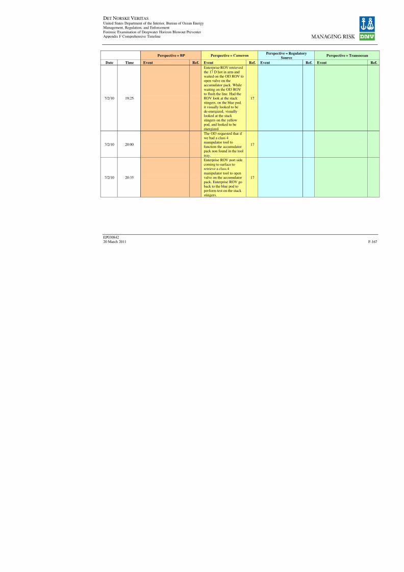
8/7/2019 DNV BOP report - Vol 2 (2)
http://slidepdf.com/reader/full/dnv-bop-report-vol-2-2 332/350
DET NORSKE VERITAS United States Department of the Interior, Bureau of Ocean EnergyManagement, Regulation, and Enforcement
Forensic Examination of Deepwater Horizon Blowout PreventerAppendix F Comprehensive Timeline
EP030842
20 March 2011
Perspective = BP Perspective = CameronPerspective = Regulatory
Source
Date Time Event Ref. Event Ref. Event Ref.
7/2/10 19:25
Enterprise ROV retrievedthe 17 D hot in arm andwaited on the OI3 ROV toopen valve on theaccumulator pack. While
waiting on the OI3 ROVto flush the line. Had theROV look at the stack stingers, on the blue pod,
it visually looked to bede-energized, visuallylooked at the stack stingers on the yellow
pod, and looked to be
energized.
17
7/2/10 20:00
The OI3 requested that if we had a class 4manipulator tool to
function the accumulatorpack non found in the tool
tray.
17
7/2/10 20:35
Enterprise ROV port side
coming to surface toretrieve a class 4manipulator tool to openvalve on the accumulator
pack. Enterprise ROV goback to the blue pod toperform test on the stack stingers.
17

8/7/2019 DNV BOP report - Vol 2 (2)
http://slidepdf.com/reader/full/dnv-bop-report-vol-2-2 333/350
DET NORSKE VERITAS United States Department of the Interior, Bureau of Ocean EnergyManagement, Regulation, and Enforcement
Forensic Examination of Deepwater Horizon Blowout PreventerAppendix F Comprehensive Timeline
EP030842
20 March 2011
Perspective = BP Perspective = CameronPerspective = Regulatory
Source
Date Time Event Ref. Event Ref. Event Ref.
7/3/10 16:25-16:31
Enterprise Rov re-positionand OI3 Rov openaccumulator pack valve 0-1,and attempt to de-energizedstack stingers lost pressure
when the 17 D hot stab onthe Blue Pod leaked, lost500 psi the starting pressurewas 3000 psi.
3
7/3/10 00:00
Enterprise ROV
instructed to go back tothe cage and wait onorders
17
7/3/10 00:47
Enterprise ROV moving
to blue pod and retrieve17D hot stab, OI3 ROV at
the accumulator pack,prepare to flush out the
stab with BOP fluid.
17
7/3/10 01:00
OI3 ROV open O1 on theaccumulator pack, hadindication of fluid comingout the pressure activation
valve. The accumulatorpack had 2000 psi at thestart of the stack stingertest. OI3 ROV closed O1
valve on the accumulatorpack.
17
7/3/10 01:21
Enterprise ROVmonitoring the blue podwhile the OI3 pressuredup the accumulator pack
to 3000 psi
17
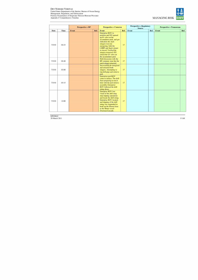
8/7/2019 DNV BOP report - Vol 2 (2)
http://slidepdf.com/reader/full/dnv-bop-report-vol-2-2 334/350
DET NORSKE VERITAS United States Department of the Interior, Bureau of Ocean EnergyManagement, Regulation, and Enforcement
Forensic Examination of Deepwater Horizon Blowout PreventerAppendix F Comprehensive Timeline
EP030842
20 March 2011
Perspective = BP Perspective = CameronPerspective = Regulatory
Source
Date Time Event Ref. Event Ref. Event Ref.
7/3/10 02:23
Enterprise ROV inposition and OI3 openedup 01 valve on theaccumulator pack, and gotindication the stack
stingers were de-energizing, both theLMRP and Stack stingerre-traced. Verified the
stingers retracted. OI3closed the O1 valve onthe accumulator pack
17
7/3/10 02:40
Held discussion with theBP company man that the
stack stinger retracted.
17
7/3/10 03:00
Successfully de-energized
and retracted bothstingers. Attempting to
trip drill pipe and retrievepod.
17
7/3/10 03:15
Enterprise port ROVcome to surface. The drillfloor preparing to run in
hole with the pod retrieveassembly. EnterpriseROV followed the drillstring down.
17
7/3/10 12:00
Enterprise ROV lostvisual of the drill sting
stop tripping operationsand locate the drill string.Enterprise ROV located,and tripping of the drill
string was suspended tohook up the Houser hoseto the Motor vesselOverseas Cascade.
17

8/7/2019 DNV BOP report - Vol 2 (2)
http://slidepdf.com/reader/full/dnv-bop-report-vol-2-2 335/350
DET NORSKE VERITAS United States Department of the Interior, Bureau of Ocean EnergyManagement, Regulation, and Enforcement
Forensic Examination of Deepwater Horizon Blowout PreventerAppendix F Comprehensive Timeline
EP030842
20 March 2011
Perspective = BP Perspective = CameronPerspective = Regulatory
Source
Date Time Event Ref. Event Ref. Event Ref.
7/3/10 13:00
Enterprise ROV standingby on the blue pod,waiting on OI3 ROV toassistants to proceed withthe blue pod recovery.
17
7/3/10 16:00
Enterprise ROV move out
to the top of the blue pod,with the ROV hook, andconnect to the blue pod,communicated to the Aft
Rotary on the rig theconnection had beenmade to the blue pod. TheEnterprise made heading
change for 160 to 120degrees. Communicatedto the rig floor to take theslack out cable and wait
on heading changes to becompleted.
17
7/3/10 16:13
Enterprise ROV re-position and OI3 ROV
open accumulator pack valve O1, the 17D hotstab in the blue pod wasleaking OI3 closed the O1
valve, Enterprise ROVreseated the 17D hot stabon the blue pod.
17
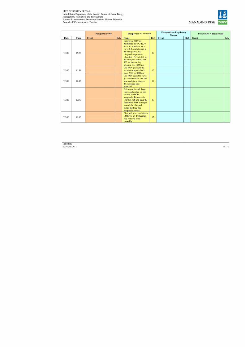
8/7/2019 DNV BOP report - Vol 2 (2)
http://slidepdf.com/reader/full/dnv-bop-report-vol-2-2 336/350
DET NORSKE VERITAS United States Department of the Interior, Bureau of Ocean EnergyManagement, Regulation, and Enforcement
Forensic Examination of Deepwater Horizon Blowout PreventerAppendix F Comprehensive Timeline
EP030842
20 March 2011
Perspective = BP Perspective = CameronPerspective = Regulatory
Source
Date Time Event Ref. Event Ref. Event Ref.
7/3/10 16:25
Enterprise ROV re-positioned the OI3 ROVopen accumulator pack valve 0-1, and attempt tode-energized stack
stingers lost pressurewhen the 17D hot stab onthe blue pod leaked, lost500 psi the starting
pressure was 3000 psi
17
7/3/10 16:31OI3 ROV pressure theaccumulator pack back from 2500 to 3000 psi
17
7/3/10 17:45
OI3 ROV open O1 valve,
got conformation that theblue pod stack stingers
de-energized andretracted.
17
7/3/10 17:50
Pick up on the Aft Tope
Drive and picked up andcleared the PODreceptacle. Remove the17D hot stab and have the
Enterprise ROV surveyedaround the blue pod.Install the blue podreceptacle covers.
17
7/3/10 18:00
Blue pod is in transit fromLMRP to aft drill center.
Pod removal wentsmoothly
17
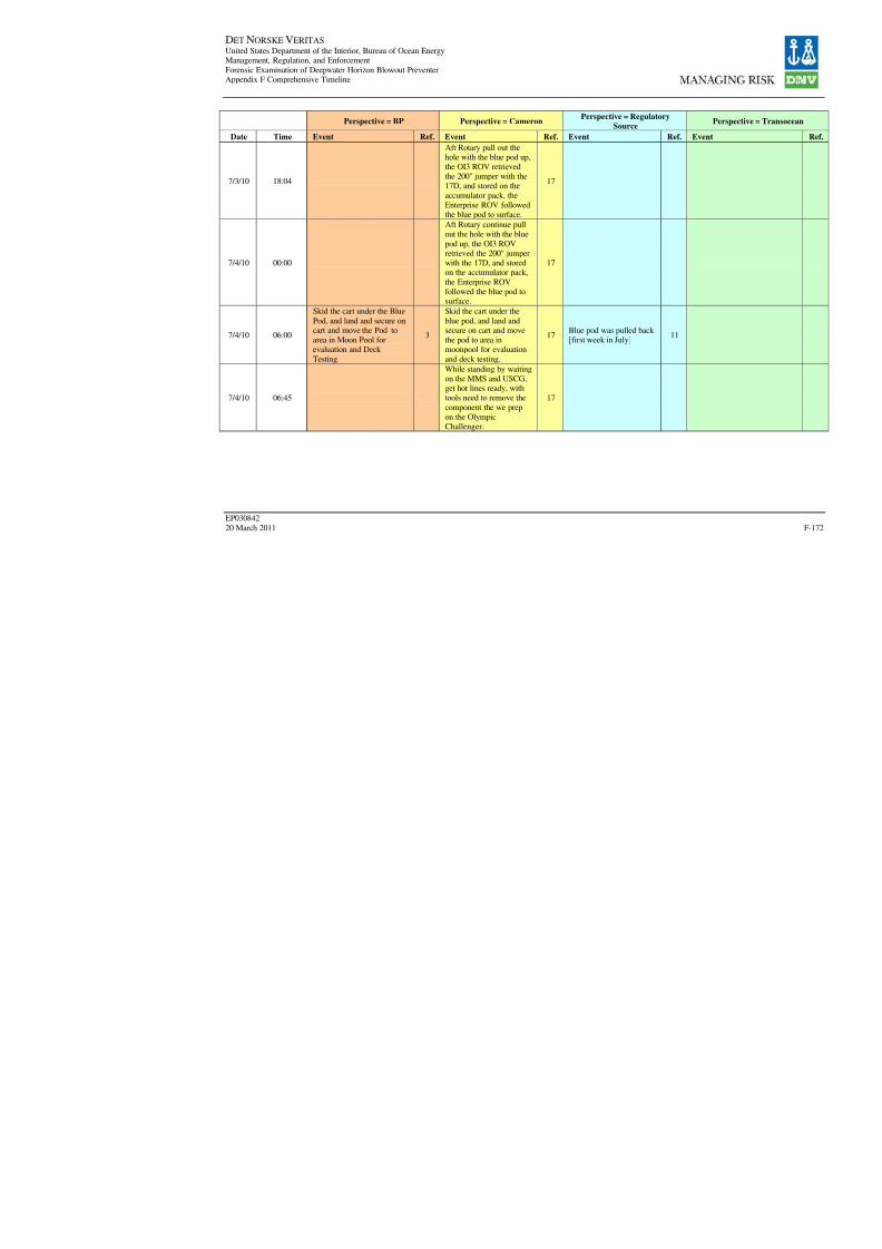
8/7/2019 DNV BOP report - Vol 2 (2)
http://slidepdf.com/reader/full/dnv-bop-report-vol-2-2 337/350
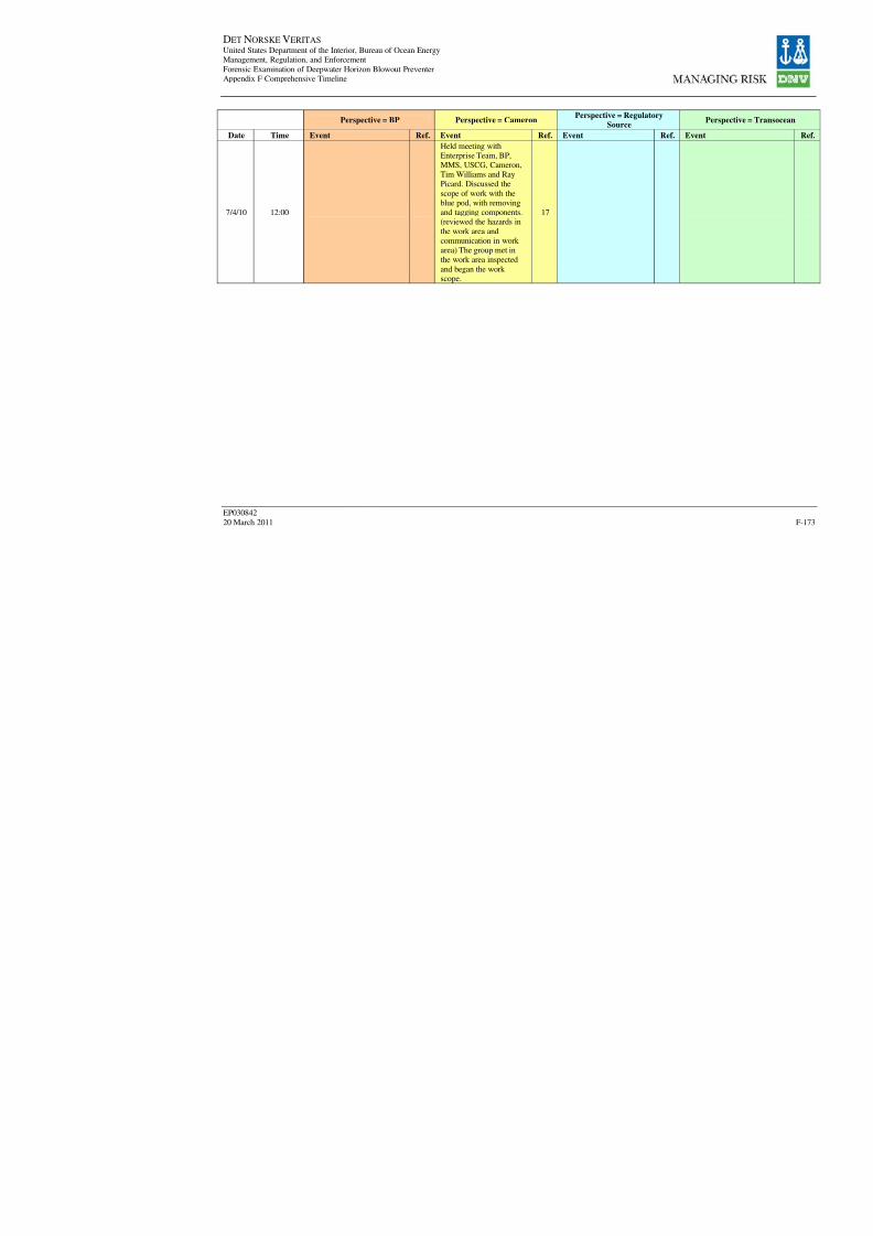
8/7/2019 DNV BOP report - Vol 2 (2)
http://slidepdf.com/reader/full/dnv-bop-report-vol-2-2 338/350
DET NORSKE VERITAS United States Department of the Interior, Bureau of Ocean EnergyManagement, Regulation, and Enforcement
Forensic Examination of Deepwater Horizon Blowout PreventerAppendix F Comprehensive Timeline
EP030842
20 March 2011
Perspective = BP Perspective = CameronPerspective = Regulatory
Source
Date Time Event Ref. Event Ref. Event Ref.
7/4/10 12:00
Held meeting withEnterprise Team, BP,MMS, USCG, Cameron,Tim Williams and RayPicard. Discussed the
scope of work with theblue pod, with removingand tagging components.(reviewed the hazards in
the work area andcommunication in work area) The group met inthe work area inspected
and began the work
scope.
17

8/7/2019 DNV BOP report - Vol 2 (2)
http://slidepdf.com/reader/full/dnv-bop-report-vol-2-2 339/350

8/7/2019 DNV BOP report - Vol 2 (2)
http://slidepdf.com/reader/full/dnv-bop-report-vol-2-2 340/350
DET NORSKE VERITAS United States Department of the Interior, Bureau of Ocean EnergyManagement, Regulation, and Enforcement
Forensic Examination of Deepwater Horizon Blowout PreventerAppendix F Comprehensive Timeline
EP030842
20 March 2011
Perspective = BP Perspective = CameronPerspective = Regulatory
Source
Date Time Event Ref. Event Ref. Event Ref.
7/4/10 14:00
Made up 1" HydraulicSupply line, for the deck teston the Blue Pod in the subsea shop
3
Made up 1" hydraulicsupply line, for the deck test on the blue pod in thesubsea shop.
17
7/4/10 15:08
Attempted to locate 1 1/2' x1' Swedge Lock fitting with5000 psi work pressure toconnect to the flow meter
for the 1' Hydraulic supplyfor the Blue Pod. (RemoveItem #15 to use to hook upthe 1" Hydraulic Supply line
for the deck test of the BluePod. This item will be putback into the lock box.
3
Attempted to located 11/2' x 1' Swedge Lock
fitting with 5000 psi work pressure to connect to theflow meter for the 1'hydraulic supply for the
blue pod. (Remove #15 touse to hook up the 1"hydraulic supply line forthe deck test of the blue
pod. This item will be putback into the lock box.Electronics Tech installedthe new PBOF cables
from the STM to SEM.
17
7/4/10 15:08Electronics Tech installedthe new PBOF cables fromthe STM to SEM.
3
7/4/10 17:52
Powered up Blue Pod on A
SEM and got verificationthat PETU wascommunicating with theBlue Pod.
3
Powered up blue pod on
A SEM and gotverification that PETUwas communicating withthe blue pod
17
7/4/10 18:00
The blue pod recoveryteam suspended scope of
work for dinner.17
7/4/10 18:00The Blue Pod RecoveryTeam suspended scope of
work for dinner.
3
Blue pod is in themoonpool. MMS andUSCG will be returningto the Enterprise at
around 11:00 AM to startthe inspection of the pod.
17
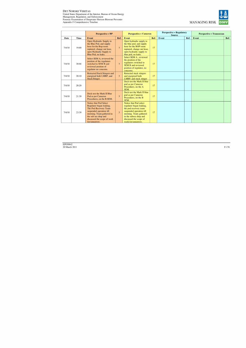
8/7/2019 DNV BOP report - Vol 2 (2)
http://slidepdf.com/reader/full/dnv-bop-report-vol-2-2 341/350
DET NORSKE VERITAS United States Department of the Interior, Bureau of Ocean EnergyManagement, Regulation, and Enforcement
Forensic Examination of Deepwater Horizon Blowout PreventerAppendix F Comprehensive Timeline
EP030842
20 March 2011
Perspective = BP Perspective = CameronPerspective = Regulatory
Source
Date Time Event Ref. Event Ref. Event Ref.
7/4/10 19:00
Open Hydraulic Supply tothe Blue Pod, and supplyhose for the Bop roomruptured, change out hose,open Hydraulic Supply to
Blue Pod, no leaks.
3
Open hydraulic supply tothe blue pod, and supplyhose for the BOP roomruptured, change out hose,open hydraulic supply to
blue pod, no leaks.
17
7/4/10 20:04
Select SEM A, reviewed theposition of the regulatorsswitched to SEM B andreviewed position of
regulator no concerns.
3
Select SEM A , reviewedthe position of theregulators switched toSEM B and reviewed
position of regulator, noconcerns.
17
7/4/10 20:10Retracted Stack Stingers andenergized both LMRP, and
Stack Stinger.
3Retracted stack stingersand energized both
LMRP, and stack stinger
17
7/4/10 20:20
Deck test the Mark II blue
pod as per CameronProcedures, on the ASEM.
17
7/4/10 21:30
Deck test the Mark II Blue
Pod as per CameronProcedures, on the B SEM.
3
Deck test the Mark II blue
pod as per CameronProcedures, on the BSEM.
17
7/4/10 23:39
Notice that Pod SelectRegulator began leaking,The Pod Recovery Team
suspended operation tillmorning. Team gathered in
the sub sea shop anddiscussed the scope of work
for tomorrow.
3
Notice that Pod selectregulator began leaking,the pod recovery team
suspended operation tillmorning. Team gathered
in the subsea shop anddiscussed the scope of
work for tomorrow.
17
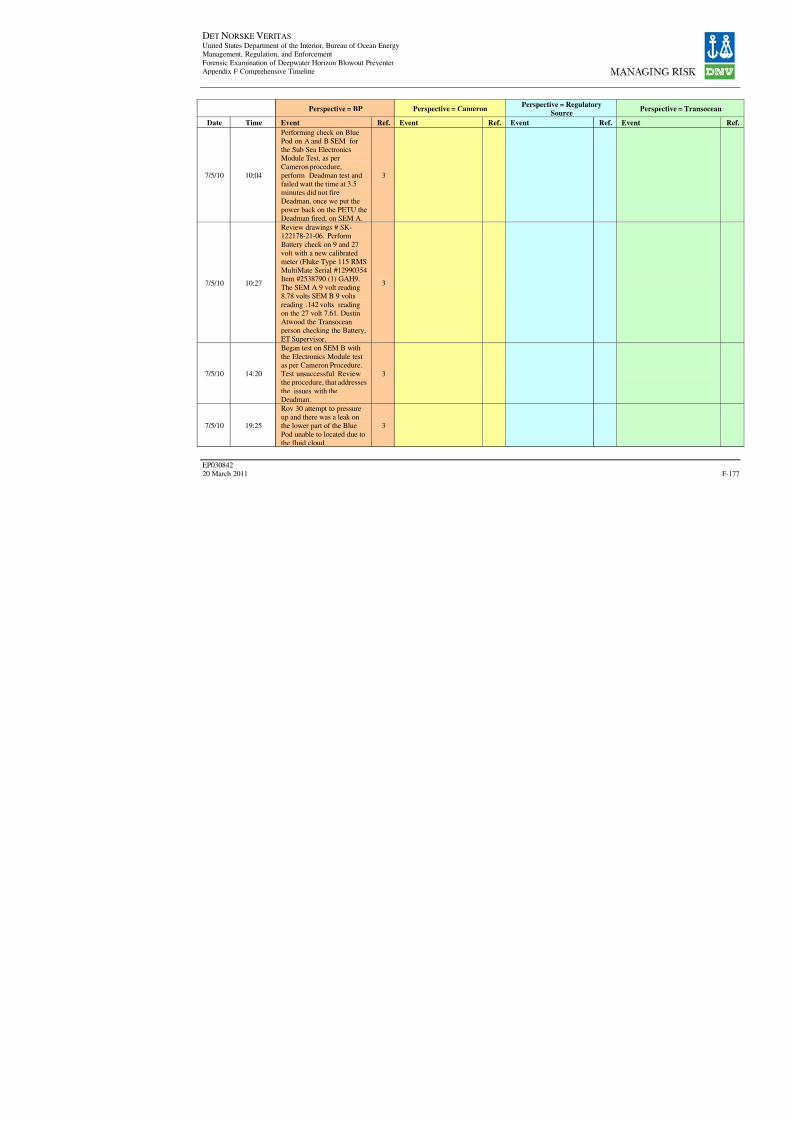
8/7/2019 DNV BOP report - Vol 2 (2)
http://slidepdf.com/reader/full/dnv-bop-report-vol-2-2 342/350
DET NORSKE VERITAS United States Department of the Interior, Bureau of Ocean EnergyManagement, Regulation, and Enforcement
Forensic Examination of Deepwater Horizon Blowout PreventerAppendix F Comprehensive Timeline
EP030842
20 March 2011
Perspective = BP Perspective = CameronPerspective = Regulatory
Source
Date Time Event Ref. Event Ref. Event Ref.
7/5/10 10:04
Performing check on BluePod on A and B SEM forthe Sub Sea ElectronicsModule Test, as perCameron procedure,
perform Deadman test andfailed watt the time at 3.5minutes did not fireDeadman, once we put the
power back on the PETU theDeadman fired, on SEM A.
3
7/5/10 10:27
Review drawings # SK-122178-21-06. PerformBattery check on 9 and 27
volt with a new calibratedmeter (Fluke Type 115 RMSMultiMate Serial #12990354Item #2538790 (1) GAH9.
The SEM A 9 volt reading8.78 volts SEM B 9 volts
reading .142 volts readingon the 27 volt 7.61. DustinAtwood the Transoceanperson checking the Battery,
ET Supervisor.
3
7/5/10 14:20
Began test on SEM B with
the Electronics Module testas per Cameron Procedure.Test unsuccessful Reviewthe procedure, that addresses
the issues with theDeadman.
3
7/5/10 19:25
Rov 30 attempt to pressureup and there was a leak onthe lower part of the Blue
Pod unable to located due tothe fluid cloud.
3

8/7/2019 DNV BOP report - Vol 2 (2)
http://slidepdf.com/reader/full/dnv-bop-report-vol-2-2 343/350
DET NORSKE VERITAS United States Department of the Interior, Bureau of Ocean EnergyManagement, Regulation, and Enforcement
Forensic Examination of Deepwater Horizon Blowout PreventerAppendix F Comprehensive Timeline
EP030842
20 March 2011
Perspective = BP Perspective = CameronPerspective = Regulatory
Source
Date Time Event Ref. Event Ref. Event Ref.
7/5/10
"The examination of thecontrol pods by Transoceanand Cameron when the podswere retrieved after theaccident (yellow on May 5-
7, 2010, and the blue pod onJuly 3-5, 2010) revealedpotential problems withAMF batteries in both
pods."
19
7/5/10 Item #1 1- 3/8" Pilot line 3
7/5/10 Item #2 1- 3/8" Pilot line 3
7/5/10Item #3 1- 1/2' Pod Selectline.
3
7/5/10Item #4 1-62 flange for thesupply line.
3
7/5/10Item #5 1- Mux cable withRough Neck connector.
3
7/5/10Item #6 1- PBOF cable
from the STM/SEM3
7/5/10 Item #7 1-STEM strap 3
7/5/10Item #8 1- PBOF cable forSEM to STM
3
7/5/10
Item #9 1- Bandit Clip for
securing the Rough Neck Connector.
3
7/5/10Item #10 1- O-Ring from thePBOF cable.
3
7/5/10Item #11 1- O-Ring from thePBOF cable.
3
7/5/10 Item #12 1-RCB cable 3
7/5/10Item #13 1- PBOF cablefrom the STM/SEM
3
7/5/10Item #14 1- O-Ring from the
PBOF cable.3
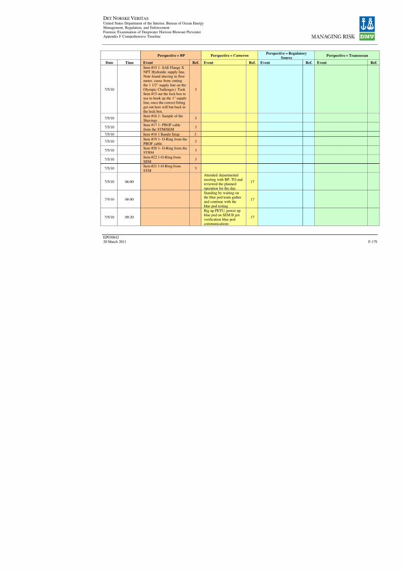
8/7/2019 DNV BOP report - Vol 2 (2)
http://slidepdf.com/reader/full/dnv-bop-report-vol-2-2 344/350
DET NORSKE VERITAS United States Department of the Interior, Bureau of Ocean EnergyManagement, Regulation, and Enforcement
Forensic Examination of Deepwater Horizon Blowout PreventerAppendix F Comprehensive Timeline
EP030842
20 March 2011
Perspective = BP Perspective = CameronPerspective = Regulatory
Source
Date Time Event Ref. Event Ref. Event Ref.
7/5/10
Item #15 1- SAE Flange XNPT Hydraulic supply line,Note found shaving in flowmeter, cause from cuttingthe 1 1/2" supply line on the
Olympic Challenger.( Took Item #15 out the lock box touse to hook up the 1" supplyline, once the correct fitting
get out here will but back inthe lock box.
3
7/5/10Item #16 1- Sample of theShavings
3
7/5/10
Item #17 1- PBOF cable
from the STM/SEM 37/5/10 Item #18 1 Bandit Strap 3
7/5/10Item #19 1- O-Ring from the
PBOF cable.3
7/5/10Item #20 1- O-Ring from theSTBM
3
7/5/10Item #22 1-O-Ring fromSEM
3
7/5/10Item #21 1-O-Ring from
STM3
7/5/10 06:00
Attended departmental
meeting with BP, TO andreviewed the plannedoperation for the day.
17
7/5/10 08:00
Standing by waiting onthe blue pod team gather
and continue with theblue pod testing
17
7/5/10 09:20
Rig up PETU, power upblue pod on SEM B gotverification blue podcommunications
17

8/7/2019 DNV BOP report - Vol 2 (2)
http://slidepdf.com/reader/full/dnv-bop-report-vol-2-2 345/350
DET NORSKE VERITAS United States Department of the Interior, Bureau of Ocean EnergyManagement, Regulation, and Enforcement
Forensic Examination of Deepwater Horizon Blowout PreventerAppendix F Comprehensive Timeline
EP030842
20 March 2011
Perspective = BP Perspective = CameronPerspective = Regulatory
Source
Date Time Event Ref. Event Ref. Event Ref.
7/5/10 09:54
Performing check on bluepod on A and B SEM forthe subsea electronicsmodule test
17
7/5/10 10:04
Performing check on bluepod on A and B SEM for
the Subsea electronicsmodule test, as perCameron procedure,perform Deadman test
and failed watt the time at3.5 minutes did not firedeadman, once we put thepower back on the PETU
the deadman fired, onSEM A.
17
7/5/10 10:27
Review drawings # SK-122178-21-06. Perform
battery check on 9 and 27volt with a new calibratedmeter (Fluke type 115RMS Multimate Serial
#12990354 Item#2538790 (1) GAH9. TheSEM A 9 volt reading8.78 volts SEM B 9 volts
reading. 0.142 voltsreading on 27 volt 7.61.Dustin Atwood the TOperson checking the
battery, ET supervisor.
17
7/5/10 11:27blue pod team break forlunch
17

8/7/2019 DNV BOP report - Vol 2 (2)
http://slidepdf.com/reader/full/dnv-bop-report-vol-2-2 346/350
DET NORSKE VERITAS United States Department of the Interior, Bureau of Ocean EnergyManagement, Regulation, and Enforcement
Forensic Examination of Deepwater Horizon Blowout PreventerAppendix F Comprehensive Timeline
EP030842
20 March 2011
Perspective = BP Perspective = CameronPerspective = Regulatory
Source
Date Time Event Ref. Event Ref. Event Ref.
7/5/10 12:00
Testing blue pod throughthe night. All functionstested correctly and thePOD was in very goodshape. There are some
minor leaks on the BOPManifold regulator andthe POD select solenoid.All in all operationally the
POD was in goodworking order. In testingthe deadman we fired theA system first. After 3 1/2
min of waiting for the
card to fire we turned thePETU on immediately atthat time the function
fired. This wasconcerning as it should
take approximately 15 secfor the SEM to reboot and47 sec for the solenoid103 to fire. We checked
the battery voltage andfound the following:deadman 27 VDC - 7.61,SEM A 9VDC - 8.77,
SEM B 0.142VDC. Weare now discussing how
to proceed.
17
7/5/10 12:37
held discussion about theblue pod, calling townand what is the next step
move forward with theblue pod
17

8/7/2019 DNV BOP report - Vol 2 (2)
http://slidepdf.com/reader/full/dnv-bop-report-vol-2-2 347/350
DET NORSKE VERITAS United States Department of the Interior, Bureau of Ocean EnergyManagement, Regulation, and Enforcement
Forensic Examination of Deepwater Horizon Blowout PreventerAppendix F Comprehensive Timeline
EP030842
20 March 2011
Perspective = BP Perspective = CameronPerspective = Regulatory
Source
Date Time Event Ref. Event Ref. Event Ref.
7/5/10 13:15
Held conference call withtown about continuecompleting the subseaelectronic module testing
17
7/5/10 13:49
Blue pod team returned tothe blue pod work area,
and prepared to continuewith Electronics Moduletest on SEM B.
17
7/5/10 14:20
Began test on SEM Bwith the Electronics
Module test as perCameron Procedure. Testunsuccessful. Review the
procedure that addressesthe issues with the
deadman
17
7/5/10 15:45
Review the paper work and sign off on the blue
pod test procedure, andthe electronics moduletest, up date the reportsand give copy to the
MMS and USCG.
17
7/5/10 -
Enterprise subsea check the pre-charge, and theelectronics tech tested thePBOF cables, on the bluepod as per procedure. Test
the PBOF cable withHelium with 15 psi alltested good.
17
7/6/10
Prepped the blue pod torun, making checks on
MUX cable and workingon Wet Mate Connection.
17
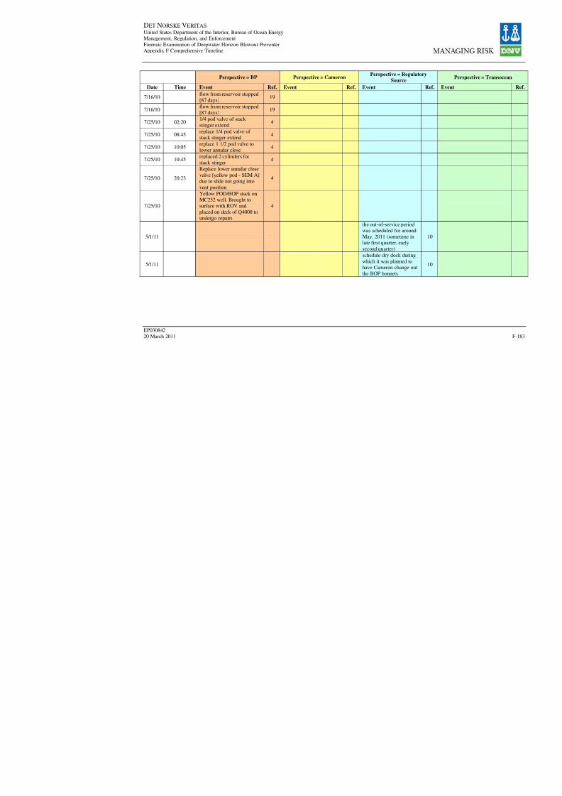
8/7/2019 DNV BOP report - Vol 2 (2)
http://slidepdf.com/reader/full/dnv-bop-report-vol-2-2 348/350
DET NORSKE VERITAS United States Department of the Interior, Bureau of Ocean EnergyManagement, Regulation, and Enforcement
Forensic Examination of Deepwater Horizon Blowout PreventerAppendix F Comprehensive Timeline
EP030842
20 March 2011
Perspective = BP Perspective = CameronPerspective = Regulatory
Source
Date Time Event Ref. Event Ref. Event Ref. 7/16/10
flow from reservoir stopped[87 days]
19
7/16/10flow from reservoir stopped[87 days]
19
7/25/10 02:201/4 pod valve of stack stinger extend
4
7/25/10 08:45replace 1/4 pod valve of stack stinger extend
4
7/25/10 10:05replace 1 1/2 pod valve tolower annular close
4
7/25/10 10:45replaced 2 cylinders for
stack stinger4
7/25/10 20:23
Replace lower annular close
valve [yellow pod - SEM A]
due to slide not going intovent position
4
7/25/10
Yellow POD/BOP stack onMC252 well. Brought tosurface with ROV andplaced on deck of Q4000 to
undergo repairs
4
5/1/11
the out-of-service period
was scheduled for aroundMay, 2011 (sometime inlate first quarter, earlysecond quarter)
10
5/1/11
schedule dry dock during
which it was planned to
have Cameron change outthe BOP bonnets
10
8/7/2019 DNV BOP report - Vol 2 (2)
http://slidepdf.com/reader/full/dnv-bop-report-vol-2-2 349/350
DET NORSKE VERITAS United States Department of the Interior, Bureau of Ocean Energy
Management, Regulation, and Enforcement
Forensic Examination Of Deepwater Horizon Blowout Preventer
Volume II Appendices
EP030842
20 March 2011
APPENDIX G
FAULT TREE
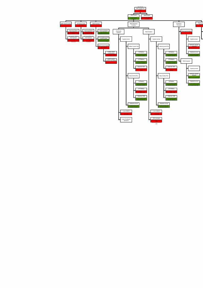
8/7/2019 DNV BOP report - Vol 2 (2)
http://slidepdf.com/reader/full/dnv-bop-report-vol-2-2 350/350
Top EventBSR closed and
sealed
BSR Close Function HP Shear CloseFunction
EDS Function AMF/DeadmanFunction
Intentional Select
from SurfaceNo eyewitness record
Accidental Selectfrom Surface
Not in close proximityto other intended
functions
Intentional Select
from SurfaceNo eyewitness record
Accidental Selectfrom Surface
Not in close proximityto other intended
functions
Intentional Select
from SurfaceEyewitness record
Accumulator functionon BOP Stack
Confirmed throughfunction testing
MUX Communicationfrom surface
Control Panelconfirmation
No corroborativeeyewitness record
LMRP unlatchControl Pod retract
No ROV confirmation
Automatic
initiation ROV initiation
System armed
Loss of MUX
see EDS
Loss of hydraulicpressure
System arm
Loss of MU
see EDS
ROV initiathydraulic pres
lossNo pressure w
cut
Yellow Control Pod
Blue Control Pod
Hydraulic circuit
Confirmed throughfunction testing
9V Battery
Confirmed throughfunction testing
27V Battery
Confirmed throughfunction testing
Solenoid 103Y
Inconclusive functiontesting
9V Battery
Confirmed throughfunction testing
27V Battery
Low voltage recordedin function test
Solenoid 103B
Confirmed throughfunction testing
BSR closed
Confirmed byevidence
BSR sealed
Confirmed failed byevidence