Embed Size (px)
Citation preview

826
Reprinted from PORTS ’95Proceedings, sponsored by the Committee on
Ports and Harbors of the Waterway, Port,Coastal, and Ocean Engineering Division/ASCE
Held March 13-15, 1995, Tampa, Florida
DOCKSIDE CONTAINER CRANES
MICHAEL A. JORDAN1, F. ASCE
ABSTRACT
Technical information for the state-of-the-art container cranes is presented.Characteristic data, geometry, speeds, productivity, cost, load control, and railreactions are included for Panamax and post-panamax shore side container cranes.Recommendations are made for the design of the wharf supporting structure forcranes. Minimum gantry rail loads are given. And the methods of wharf analysisand design considerations are discussed.
INTRODUCTION
Container traffic is expected to grow between 5 and 8 percent per year or even more.Post-panamax ships with 16 containers abeam and 4800 TEU are operating. Sixthousand TEU ships with 18 containers abeam are planned. Large feeder ports willload and unload the entire ship’s cargo at one berthing.
Post-panamax cranes service these large ships. They are bigger, 172 feet of outreach.They are heavier. They are more sophisticated, with powerful on board computers,fiber optics controls and communications, and electronic load control. They requiremore power.
1 Structural Engineer, Chief Executive Officer, Liftech Consultants Inc., 3666 Grand Ave., Oakland, CA 94610, Phone 510-832-5606, Fax 510-832-2436.
© 1995 Liftech Consultants Inc.
DOCKSIDE CONTAINER CRANES 827
Many new concepts are being explored. New super cranes will be capable of 50 to70 moves per hour. Yard equipment is improving, so the capability of the highproductivity cranes can be used.
The new cranes require new design criteria for crane girder strength and for wharfgeometry.
This paper discusses five types of containers cranes, the characteristics of the state-of-the-art post-panamax container crane, and recommends design criteria for thedesign of new wharf structures supporting the cranes.
CONVENTIONAL CRANES
The conventional and modified A-frame crane with a single trolley and one operatoris the work horse of the industry. The Paceco cranes are the archetype. The gage is50’ to 100’. If required for aircraft clearance, articulated boom and low profilecranes are used. Current production is 20 to 35 containers an hour depending on theyard operation work rules and the characteristics of the cranes. Containers can behandled in either a single cycle mode or a double cycle mode.
Most new cranes are conventional, with 50’ backreach, 100’ gage, and 145’ to 160’outreach to service 16 wide post-panamax ships. Some cranes on order have 172’outreach and can service 18 wide ships. Even if 18 wide capacity is not needed, theextended outreach improves production since the trolley does not go into the slowdown zone at the end of the boom.
In the United States most trolleys are fleet through: the main hoist is on the frameand the ropes fleet through the trolley. This reduces the trolley weight butcomplicates the main hoist reeving. In Europe, many cranes have the main hoist onthe trolley. This significantly increases the trolley weight but simplifies the reeving.For extreme outreach cranes, the hoist-on-trolley scheme is often most appropriate.Operators and manufacturers are debating which is better. It’s undecided, but expectmore hoist on trolley cranes. Even though some crane components are heavier, theoverall weight of the crane is not increased significantly.
The new, large post-panamax cranes are as productive as the Panamax cranes, sincethe new cranes are faster and have better anti-sway load control than the old smallcranes. This is remarkable.
New conventional A-frame cranes cost 5 to 7 million dollars and take 14 to 24months to deliver. Articulated boom cranes cost a little more. Low profile cranescost a lot more, 50% more. Many cranes are shipped fully erected, tested, and nearlyready for operation. This increases cost but reduces disruption at the wharf.
© 1995 Liftech Consultants Inc.
828 PORTS ‘95
DUAL HOIST SINGLE TROLLEY CRANES
Dual hoist cranes are conventional cranes with a second hoist added over the wharf.This increases productivity by about 50%, increases initial cost by 30% to 50%, addsone more operator, and increases operating costs. These costs are justified if moreproductivity is needed and it is impractical to add more cranes over the ship.
During unloading, the trolley picks the container from the ship and delivers it to ashuttle at the portal beam elevation. The shuttle moves landward under the secondhoist. The second hoist, operated by the second operator, picks the container and setsit on a chassis. Vice versa for loading. Containers can only be handled in the singlecycle mode.
The Baltimore Sumitomo cranes at Seagirt Marine Terminal and the ECT Nelconcranes at Delta Terminal in Rotterdam are the archetypes.
DUAL HOIST ELEVATING PLATFORM CRANES
Dual hoist elevating platform cranes are dual hoist single trolley cranes except theshuttle runway elevates to the ideal elevation. The Virginia Intentional TerminalsNIT Kone cranes are the only cranes of this type. They cost more than dual hoistplatform cranes and produce more.
The operator’s cab is not on the trolley, but on a separate runway next to trolleyrunway. This improves operator comfort and productivity.
DUAL HOIST ELEVATING GIRDER CRANE
The dual hoist elevating girder crane is a new idea with a patent applied for by Mr.C. Davis Rudolf III and Mr. Anthony Simkus of VIT. The crane is a conventionalcrane except the entire trolley runway elevates. The boom and trolley girders can beset to the ideal elevation for each vessel and load. Containers can be handled in bothsingle cycle and dual cycle modes.
The dual hoist elevating girder crane is still being developed. Two manufacturers areinvestigating the feasibility of building the crane. The crane is expected to beappropriate for ports that service a wide variety of vessels ranging from post-panamax container ships to barges.
DUAL HOSTS AND DUAL TROLLEY CRANES
Paceco has conceived of a new crane that can truly be called a supercrane. It willproduce twice as many moves as a conventional crane. But at what cost?
The crane is a conventional crane with one trolley runway, except that it has twotrolleys and a shuttle that operate on the runway and a chassis guide system that© 1995 Liftech Consultants Inc.

DOCKSIDE CONTAINER CRANES 829
operates at the portal tie. At least two operators will be required. The trolleys parkover the container stack on the ship. The chassis guide parks under the shore trolley.For unloading, the ship trolley picks a container from the ship, lifting the containerfull height to get above the shuttle. The shuttle, which must be wide enough to clearthe longest container, moves under the ship trolley and travels to the shore trolley.The shore trolley picks the container and when clear, lowers the container into thechassis guide and onto the chassis. For loading, the cycle is reversed. Containerscan only be handled in the single cycle mode.
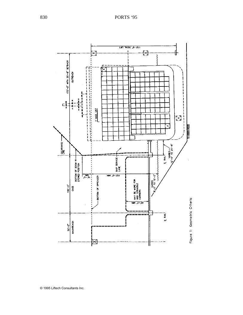
GEOMETRIC CRITERIA
Figure 1 shows a typical cross section of a wharf servicing C10 post-panamax ships.Notice the boom does not need to be fully raised to clear the ship. Normally theboom is stowed partially raised.
The unusually large 25’-8” set back provides for a ship service lane.
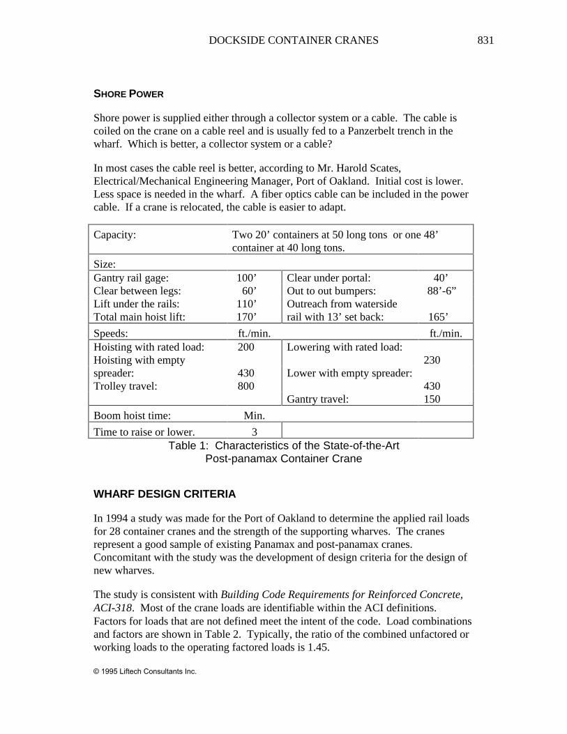
THE STATE-OF-THE-ART POST-PANAMAX CONTAINER CRANE
Typical characteristics of the state-of-the-art conventional and dual hoist singletrolley post-panamax container crane are shown in Table 1.
MAIN HOIST REEVING AND LOAD CONTROL
Electronic load control, with a four-fall trolley is the state-of-the-art. Electronicssystem are smooth and operator friendly. They will adapt to automation. Thehydraulic six-fall systems are no longer needed.
List, trim, and skew control (±3°) use hydraulic systems which also provide snagprotection. Snag protection absorbs the kinetic energy of the moving machinerywhen the empty spreader snags.
© 1995 Liftech Consultants Inc.
830 PORTS ‘95
© 1995 Liftech Consultants Inc.
DOCKSIDE CONTAINER CRANES 831
SHORE POWER
Shore power is supplied either through a collector system or a cable. The cable iscoiled on the crane on a cable reel and is usually fed to a Panzerbelt trench in thewharf. Which is better, a collector system or a cable?
In most cases the cable reel is better, according to Mr. Harold Scates,Electrical/Mechanical Engineering Manager, Port of Oakland. Initial cost is lower.Less space is needed in the wharf. A fiber optics cable can be included in the powercable. If a crane is relocated, the cable is easier to adapt.
Capacity: Two 20’ containers at 50 long tons or one 48’container at 40 long tons.
Size:Gantry rail gage: 100’ Clear under portal: 40’Clear between legs: 60’ Out to out bumpers: 88’-6”Lift under the rails:Total main hoist lift:
110’170’
Outreach from watersiderail with 13’ set back: 165’
Speeds: ft./min. ft./min.Hoisting with rated load:Hoisting with empty
200 Lowering with rated load:230
spreader:Trolley travel:
430 800
Lower with empty spreader:430
Gantry travel: 150
Boom hoist time: Min.
Time to raise or lower. 3Table 1: Characteristics of the State-of-the-Art
Post-panamax Container Crane
WHARF DESIGN CRITERIA
In 1994 a study was made for the Port of Oakland to determine the applied rail loadsfor 28 container cranes and the strength of the supporting wharves. The cranesrepresent a good sample of existing Panamax and post-panamax cranes.Concomitant with the study was the development of design criteria for the design ofnew wharves.
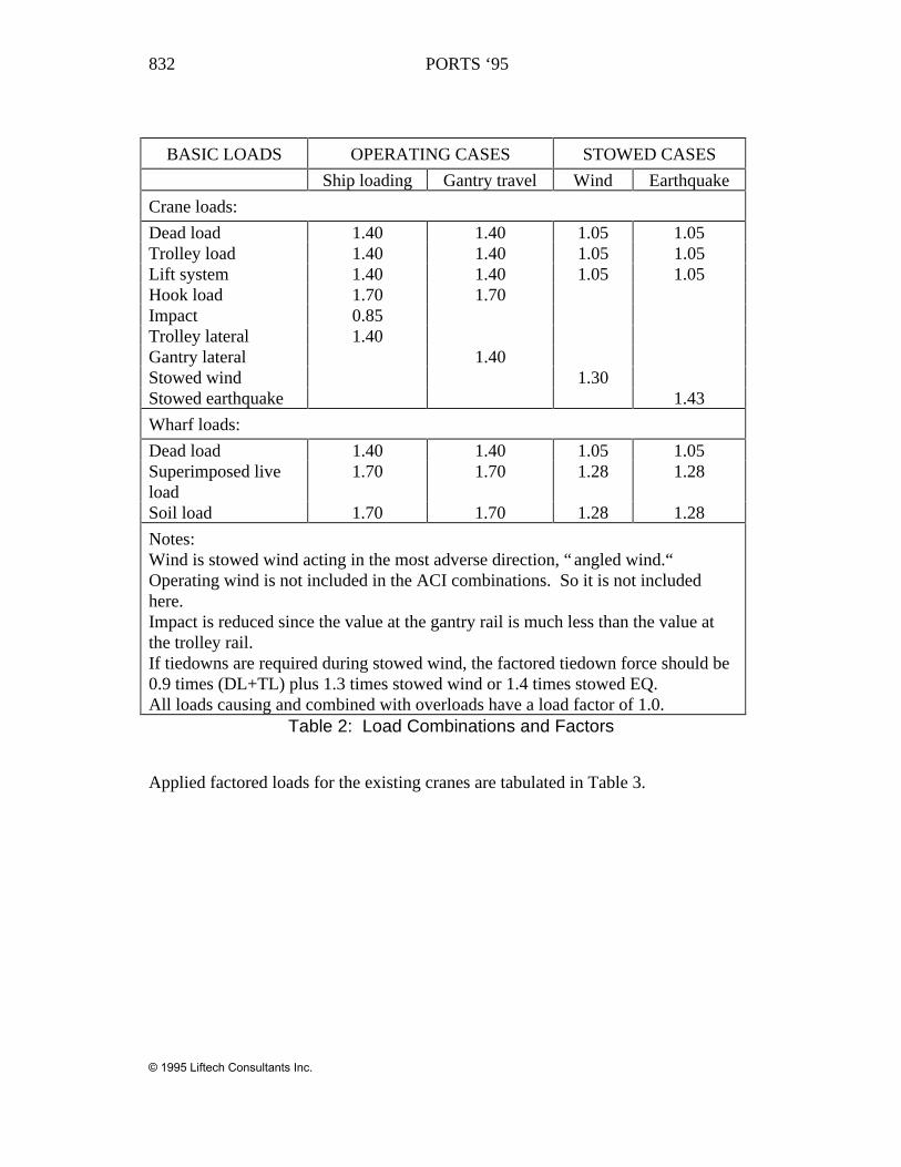
The study is consistent with Building Code Requirements for Reinforced Concrete,ACI-318. Most of the crane loads are identifiable within the ACI definitions.Factors for loads that are not defined meet the intent of the code. Load combinationsand factors are shown in Table 2. Typically, the ratio of the combined unfactored orworking loads to the operating factored loads is 1.45.
© 1995 Liftech Consultants Inc.
832 PORTS ‘95
BASIC LOADS OPERATING CASES STOWED CASES
Ship loading Gantry travel Wind Earthquake
Crane loads:
Dead load 1.40 1.40 1.05 1.05Trolley load 1.40 1.40 1.05 1.05Lift system 1.40 1.40 1.05 1.05Hook load 1.70 1.70Impact 0.85Trolley lateral 1.40Gantry lateral 1.40Stowed wind 1.30Stowed earthquake 1.43
Wharf loads:
Dead load 1.40 1.40 1.05 1.05Superimposed liveload
1.70 1.70 1.28 1.28
Soil load 1.70 1.70 1.28 1.28
Notes:Wind is stowed wind acting in the most adverse direction, “ angled wind.“Operating wind is not included in the ACI combinations. So it is not includedhere.Impact is reduced since the value at the gantry rail is much less than the value atthe trolley rail.If tiedowns are required during stowed wind, the factored tiedown force should be0.9 times (DL+TL) plus 1.3 times stowed wind or 1.4 times stowed EQ.All loads causing and combined with overloads have a load factor of 1.0.
Table 2: Load Combinations and Factors
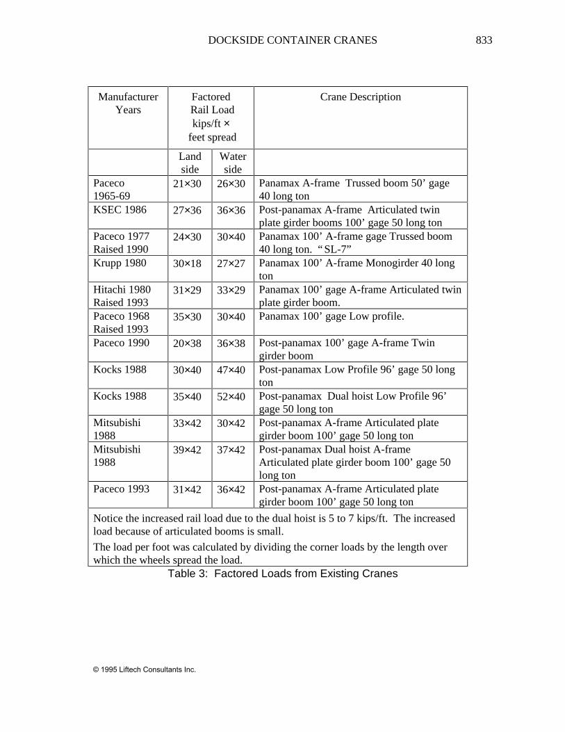
Applied factored loads for the existing cranes are tabulated in Table 3.
© 1995 Liftech Consultants Inc.
DOCKSIDE CONTAINER CRANES 833
ManufacturerYears
Factored Rail Loadkips/ft ×
feet spread
Crane Description
Landside
Waterside
Paceco1965-69
21×30 26×30 Panamax A-frame Trussed boom 50’ gage40 long ton
KSEC 1986 27×36 36×36 Post-panamax A-frame Articulated twinplate girder booms 100’ gage 50 long ton
Paceco 1977Raised 1990
24×30 30×40 Panamax 100’ A-frame gage Trussed boom40 long ton. “SL-7”
Krupp 1980 30×18 27×27 Panamax 100’ A-frame Monogirder 40 longton
Hitachi 1980Raised 1993
31×29 33×29 Panamax 100’ gage A-frame Articulated twinplate girder boom.
Paceco 1968Raised 1993
35×30 30×40 Panamax 100’ gage Low profile.
Paceco 1990 20×38 36×38 Post-panamax 100’ gage A-frame Twingirder boom
Kocks 1988 30×40 47×40 Post-panamax Low Profile 96’ gage 50 longton
Kocks 1988 35×40 52×40 Post-panamax Dual hoist Low Profile 96’gage 50 long ton
Mitsubishi1988
33×42 30×42 Post-panamax A-frame Articulated plategirder boom 100’ gage 50 long ton
Mitsubishi1988
39×42 37×42 Post-panamax Dual hoist A-frameArticulated plate girder boom 100’ gage 50long ton
Paceco 1993 31×42 36×42 Post-panamax A-frame Articulated plategirder boom 100’ gage 50 long ton
Notice the increased rail load due to the dual hoist is 5 to 7 kips/ft. The increasedload because of articulated booms is small.
The load per foot was calculated by dividing the corner loads by the length overwhich the wheels spread the load.
Table 3: Factored Loads from Existing Cranes
© 1995 Liftech Consultants Inc.
834 PORTS ‘95
RECOMMENDED DESIGN CRITERIA FOR NEW CRANE RUNWAYS
The strength of the girder should be determined using ACI 318. Prestressed concretepiles should be designed using Section 4.7.6 of the PCI Design Handbook, 4thedition, with modifications for pile slenderness.
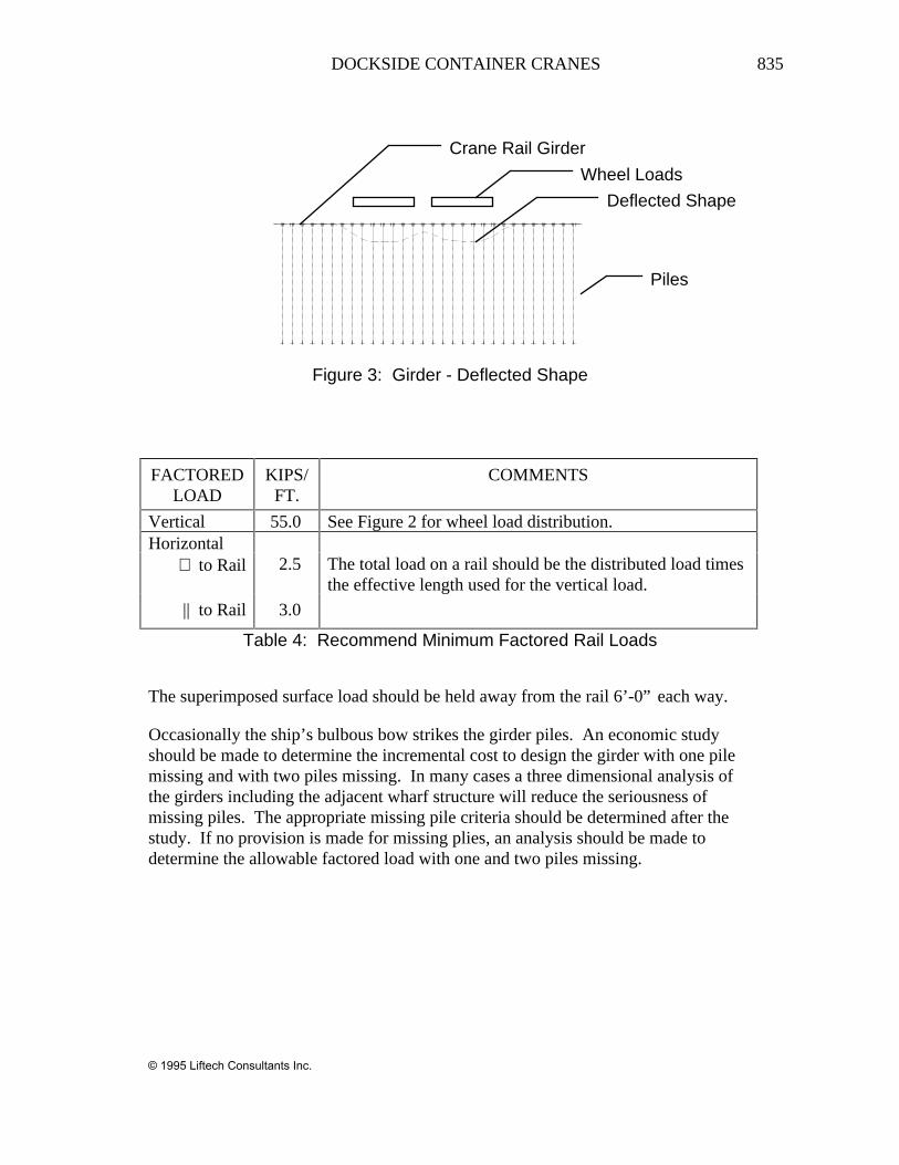
For girders on piles, the stiffness of the piles and soil should be included. For girderson spread footings, the beam on elastic foundation method should be used. Thegirders may be modeled with cracked section properties, since the girder momentswill crack the section.
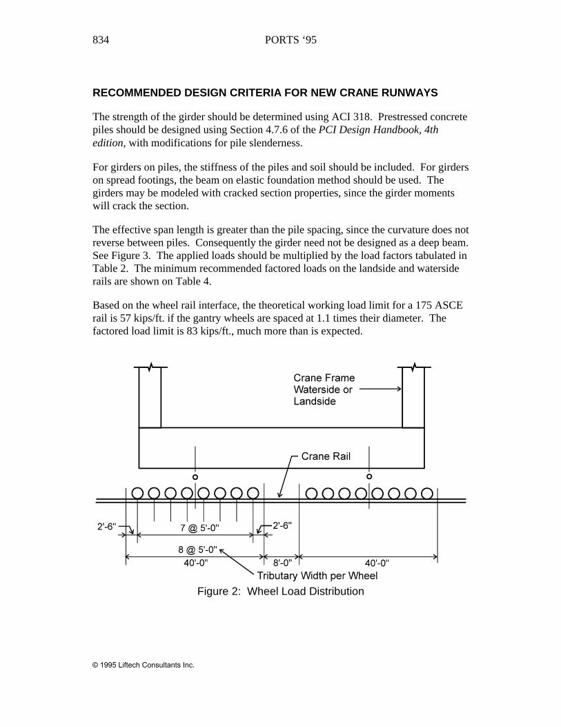
The effective span length is greater than the pile spacing, since the curvature does notreverse between piles. Consequently the girder need not be designed as a deep beam.See Figure 3. The applied loads should be multiplied by the load factors tabulated inTable 2. The minimum recommended factored loads on the landside and watersiderails are shown on Table 4.
Based on the wheel rail interface, the theoretical working load limit for a 175 ASCErail is 57 kips/ft. if the gantry wheels are spaced at 1.1 times their diameter. Thefactored load limit is 83 kips/ft., much more than is expected.
Figure 2: Wheel Load Distribution
© 1995 Liftech Consultants Inc.
DOCKSIDE CONTAINER CRANES 835
Wheel Loads
Deflected Shape
Piles
Crane Rail Girder
Figure 3: Girder - Deflected Shape
FACTOREDLOAD
KIPS/FT.
COMMENTS
Vertical 55.0 See Figure 2 for wheel load distribution.Horizontal
⊥ to Rail 2.5 The total load on a rail should be the distributed load timesthe effective length used for the vertical load.
|| to Rail 3.0
Table 4: Recommend Minimum Factored Rail Loads
The superimposed surface load should be held away from the rail 6’-0” each way.
Occasionally the ship’s bulbous bow strikes the girder piles. An economic studyshould be made to determine the incremental cost to design the girder with one pilemissing and with two piles missing. In many cases a three dimensional analysis ofthe girders including the adjacent wharf structure will reduce the seriousness ofmissing piles. The appropriate missing pile criteria should be determined after thestudy. If no provision is made for missing plies, an analysis should be made todetermine the allowable factored load with one and two piles missing.
© 1995 Liftech Consultants Inc.
836 PORTS ‘95
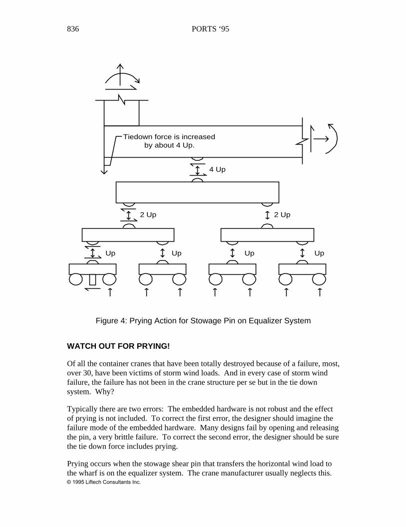
Up Up Up Up
2 Up
4 Up
2 Up
Tiedown force is increasedby about 4 Up.
Figure 4: Prying Action for Stowage Pin on Equalizer System
WATCH OUT FOR PRYING!
Of all the container cranes that have been totally destroyed because of a failure, most,over 30, have been victims of storm wind loads. And in every case of storm windfailure, the failure has not been in the crane structure per se but in the tie downsystem. Why?
Typically there are two errors: The embedded hardware is not robust and the effectof prying is not included. To correct the first error, the designer should imagine thefailure mode of the embedded hardware. Many designs fail by opening and releasingthe pin, a very brittle failure. To correct the second error, the designer should be surethe tie down force includes prying.
Prying occurs when the stowage shear pin that transfers the horizontal wind load tothe wharf is on the equalizer system. The crane manufacturer usually neglects this.© 1995 Liftech Consultants Inc.
DOCKSIDE CONTAINER CRANES 837
Even if the manufacturer reports that no tie downs are needed there still may be aproblem. Figure 4 shows the loads and load path for the effects of the horizontalforce tending to rotate the equalizer system. If the shear pin is on the main equalizerbeam the problem is still there. If the shear pin is on the sill beam, there is no prying.
CONCLUSIONS
The marine container industry continues to expand. New, more productive cranesare needed. Some super cranes will double productivity.
Data for extant and near future container cranes is given.
New wharves must be designed to carry the new cranes and allow for uninterrupteduse of the quay. One approach is to provide a ship’s service lane.
Shore power will be by cable reel to save space, allow for relocation, and providefiber optics communication.
The recommended design of new wharves uses load factor methods. Load factorsare given for the crane and wharf loads. The effect of damage from a ship should beconsidered
© 1995 Liftech Consultants Inc.