Embed Size (px)
Citation preview
Telecommunications Technical Standards – Private Public Partnership Fraser Health Better health. Best in Health Care.
2116486.09 Appendix 3E – Cable Infrastructure Standard (Surrey Memorial Hospital Project) EXECUTION COPY
APPENDIX 3E
CABLE INFRASTRUCTURE STANDARD
1. STRUCTURED CABLING
1.1. General Requirements
1.1.1. Comply with the following standards (latest versions) when designing and installing structured cabling:
• TIA/EIA 526-7, 14 standards for Optical Power Loss measurement of single mode and multimode fibre cable plant.
• TIA/EIA 568-C.1 Commercial Building Telecommunications Cabling Standard – Part 1 General Requirements.
• TIA/EIA 568- C.2 Commercial Building Telecommunications Cabling Standard – Part 2 Balanced Twisted Pair Cabling Components.
• TIA /EIA 568-C.3 Commercial Building Telecommunications Cabling Standard – Part 3 Optical Fiber Cabling Component Standard.
• TIA/EIA 568-B.2-10 Augmented Category 6 requirements.
• TIA/EIA 569- B Commercial Building Standard for Telecommunications Pathways and Spaces.
• TIA/EIA – 606-A Administration Standard for the Telecommunications Infrastructure of Commercial Buildings.
• ANSIA/TIA/EIA – 607A (J-STD-607-A-2002) Commercial Building Grounding and Bonding Requirements for Telecommunications.
• ANSI/TIA-942-2 Telecommunications Infrastructure Standard for Data Centers.
• ANSI/TIA/EIA-758-A Customer Owned Outside Plant Telecommunications Cabling Standard.
• ANSI/TIA-1179 Healthcare Facility Telecommunications Cabling Standard.
• ANSI/TIA TSB-162 “Telecommunications Cabling Guidelines for Wireless Access Points.
• CSA Z318.7-95 Commissioning of Communications Systems in Health Care Facilities.
Telecommunications Technical Standards – Private Public Partnership Fraser Health Better health. Best in Health Care.
2116486.09 Appendix 3E – Cable Infrastructure Standard (Surrey Memorial Hospital Project) EXECUTION COPY
• BICSI TDM, TCIM, NTS, OSP and WD manuals.
1.1.2. Complete the design and installation of the structured cabling in accordance with the drawings and figures in Attachment 1 [Fraser Health – Telecommunications Standard Drawing List] to this Appendix.
1.1.3. The demarcation shall meet the requirements of the service provider.
1.1.4. The complete installation shall be installed and tested by a Belden certified contractor.
1.1.5. Each work area outlet shall consist of one 4-pair Category 6 cable dedicated to voice application and one 4-pair Category 6 cable dedicated to data. The third cable shall be a spare cable and can be used for voice or data application. Category 6 termination technique shall be used. All these horizontal cables including those from wireless access point and intercom outlets shall be terminated on GigaBIX termination hardware located in the main telecommunications closet (“MTC”) and the local telecommunications closets (“LTC”).
1.1.6. The term telecommunications wiring and system shall be used to describe: • data computer systems wiring • intercom systems wiring • telephone system wiring
1.1.7. The following list of common services and systems should be considered when horizontal cabling is designed. (The list is not intended to be complete) • Voice telecommunications services • Premises switching equipment • Data Communication • Local area networks • Video • Other builing signaling systems (building automation systems such as
fire, security, HVAC, etc. as codes permit.)
Telecommunications Technical Standards – Private Public Partnership Fraser Health Better health. Best in Health Care.
2116486.09 Appendix 3E – Cable Infrastructure Standard (Surrey Memorial Hospital Project) EXECUTION COPY
1.2. Products
1.2.1. General
1.2.1.1. All horizontal products that are installed for data, intercom, and voice, when combined, shall meet Cat 5e permanent link performance as per TIA/EIA 568-B.1 and B.2. The products installed for the end-to-end solution shall have been tested by an independent testing agency, such as UL or ETL, to ensure that the integrated system installed meets channel performance. The manufacturer(s) of the proposed solution must have an ISO 9000 program in place to ensure the channel testing is a standard part of their quality assurance.
1.2.1.2. The structured cabling system shall be a complete, end-to-end Belden system. Installation to be as outlined below.
1.2.2. Cable
1.2.2.1. All horizontal telecommunications cabling shall be BELDEN IBDN 10GX, 4-pair, 100 ohm, UTP, 23 AWG, UTP solid, unbonded Category 6 certified or better.
1.2.2.2. All cables installed shall meet the flame-spread requirements of the local authority.
1.2.2.3. Voice intra-building backbone riser cable shall be a minimum of 50 pair, 100 ohm, UTP, 24 AWG, Solid, Category 5E certified and shall be installed from the MTC to each LTC. The voice riser shall be sized by allocating one pair for each horizontal voice cable originating from that telecommunications closet plus 25% spare pairs. The pair count shall be rounded to the next 25 pair multiple. The voice riser cables shall be installed in a star wired configuration.
1.2.2.4. Install a 100 ohm, UTP, 24 AWG, Solid, Category 5E certified intra-building backbone entrance tie cable from the demarcation for the Facility and the voice equipment room (PABX input) or MTC if co-located. Provide a cable with sufficient fiber pairs to support all requirements for the Facility.
1.2.2.5. Terminate the cable on IDC terminations at each end. Provide cable management accessories as recommended by the Manufacturer.
1.2.2.6. Intercom riser cable when used shall be a minimum of 50 pair, 100 ohm, UTP, 24 AWG, Solid, Category 5E certified. The intercom riser shall be sized by allocating two pair for each horizontal intercom cable originating from that telecommunications closet. The pair count shall be rounded to the next 25 pair multiple. Install intercom riser cable between the
Telecommunications Technical Standards – Private Public Partnership Fraser Health Better health. Best in Health Care.
2116486.09 Appendix 3E – Cable Infrastructure Standard (Surrey Memorial Hospital Project) EXECUTION COPY
intercom service for the facility or MTC if co-located and each telecommunications closet on each floor. The intercom riser cables shall be installed in a star wired configuration.
1.2.2.7. From the MTC install (and terminate) a 12 tight buffered fiber cable to each LTC and data equipment (server) rooms if specified. The fiber shall be OM3 grade laser optimized 50/125 μm, multi mode (FX2000). The fiber shall have maximum attenuation of 2.6/1.25 db/km and minimum information transmission capacity of 2000/500 MHz/km at wavelengths of 850/1300 nm respectively. The fiber shall support 10 GIGABIT ETHERNET over the distance installed. The fiber cables shall be terminated in a rack mounted FiberExpress Manager interconnect box complete with connector modules (cartridge type) and LC connectors at each end. If crimp connectors are used they shall be the style that has the fibre pre-loaded and polished at the factory.
1.2.2.8. Campus inter-building data cable shall be all dielectric cable. Provide a data cable with sufficient fibers to support all requirements for the Facility. The fiber cable shall be loose tube gel filled. The fiber shall be 12 strand OS2 grade low water peak (LPW) Belden single mode enhanced and 12 strands 50/125 μm OM3 laser optimized multimode (FX2000). The multimode fiber shall have maximum attenuation of 2.6/1.25 db/km and minimum information transmission capacity of 2000/500 MHz/km at wavelengths of 850/1300 nm respectively. The fiber shall support 10 Gigabit Ethernet for the distance installed. If crimp connectors are used they shall be the style that has the fiber preloaded and polished at the factory. Manufacturer recommended breakout/fanout kits with fan out tubing shall be used. If the cable is routed underground it shall be installed in conduit. The conduit shall be sized with 100% spare cable capacity based on a 40% fill.
1.2.2.9. Install and terminate a UTP, 22 AWG outside plant cable between buildings for voice. Provide cable with sufficient fiber pairs to support all requirements for the Facility. The cable shall have a filled core. Provide primary protection on both ends as required by the local authority. If the cable is routed underground it shall be installed in conduit. The conduit shall be sized with 100 % spare cable capacity based on a fill of 40%. Terminate the cable on IDC terminations.
1.2.2.10. Where raceway size is not specified, the raceway shall be sized to not exceed a 28% fill ratio after all the cables are installed assuming there are two 90º bends in the run. Where there are zero bends in the raceway, the fill ratio shall be increased to 40%.

Telecommunications Technical Standards – Private Public Partnership Fraser Health Better health. Best in Health Care.
2116486.09 Appendix 3E – Cable Infrastructure Standard (Surrey Memorial Hospital Project) EXECUTION COPY
1.2.2.11. In acute sites, cabling requirements for BAS System (Building Automation System) shall be coordinated with Division 15.
1.2.2.12. In acute sites, one (1) Category 6 cable shall be installed from telecommunications closet to each specified location for voice connection of security, fire alarm, bell, meter clock circuit, elevator phone, secure access and hydro utility meter systems. Coordinate with each service provider for exact number of cables and locations.
1.2.2.13. For data connection to UPS units, modems (ADSL, eADSL, Fax, PBX dial-up, E10, E100 & E200 dial-up, etc.), and Servers (Print, Security, Clinical, etc.), 24 or 48 port angled UTP patch panel shall be installed at the top section of the rack or cabinet at 1U space below last fiber patch panel with tie cables terminated on GigaBix connector just above the harness cable field.
1.2.3. Termination Hardware
1.2.3.1. All data, intercom and voice cables shall be terminated on Category 6, 8 position modular (RJ45) jacks (Belden 10GX Modules) at the work areas.
1.2.3.2. All 8-position modular jacks (RJ45) terminations shall be made using the TIA/EIA 568A pin configuration.
1.2.3.3. All horizontal cables shall terminate in the telecommunications closets using IDC cross connects on the wall. Where existing IDC blocks exist, they shall be replaced with new whenever feasible. In new telecommunications closet, IDC shall be mounted on Belden 12-Connector GigaBix mount. GigaBix cable management module shall be installed behind GigaBix mount to facilitate cable routing. Manufactured standoff (AX102190) shall be installed behind GigaBix management ring. The data drops shall be extended from a separate IDC cross connect to a rack mounted 8-position modular plug (RJ45) using a harness cable.
1.2.3.4. Separate GigaBix mount shall be used to terminate the horizontal cables, intercom riser, and voice and data riser cables in each telecommunications closet (See Figure 3).
Telecommunications Technical Standards – Private Public Partnership Fraser Health Better health. Best in Health Care.
2116486.09 Appendix 3E – Cable Infrastructure Standard (Surrey Memorial Hospital Project) EXECUTION COPY
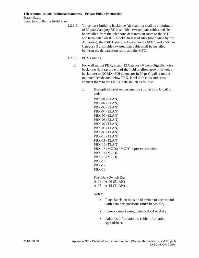
1.2.3.5. Voice intra-building backbone (tie) cabling shall be a minimum of 50 pair Category 5E unshielded twisted pair cables and shall be installed from the telephone demarcation room to the MTC and terminated on IDC blocks. In leased sites (not owned by the Authority), the PABX shall be located in the MTC, and a 50 pair Category 3 unshielded twisted pair cable shall be installed between the demarcation room and the MTC.
1.2.3.6. PBX Cabling
.1 For wall mount PBX, install 12 Category 6 from GigaBix voice backbone field (at the end of the field to allow growth of voice backbone) to QCBIX46DI connector in 50 pr GigaBix mount mounted beside and below PBX, label both ends and cross-connect them to the FIRST data switch as follows:
.1 Example of label on designation strip at both GigaBix ends PBX-01 (ELAN) PBX-02 (ELAN) PBX-03 (ELAN) PBX-04 (ELAN) PBX-05 (ELAN) PBX-06 (ELAN) PBX-07 (TLAN) PBX-08 (TLAN) PBX-09 (TLAN) PBX-10 (TLAN) PBX-11 (TLAN) PBX-12 (TLAN) PBX-13 (MOD); “MOD” represents modem PBX-14 (MOD) PBX-15 (MOD) PBX-16 PBX-17 PBX-18 First Data Switch End A-01 – A-06 (ELAN) A-07 – A-12 (TLAN) Notes:
• Place labels on top side of switch to correspond with data port positions (must be visible).
• Cross-connect using pigtails A-01 to A-12.
• Add this information to cable information spreadsheet.
Telecommunications Technical Standards – Private Public Partnership Fraser Health Better health. Best in Health Care.
2116486.09 Appendix 3E – Cable Infrastructure Standard (Surrey Memorial Hospital Project) EXECUTION COPY
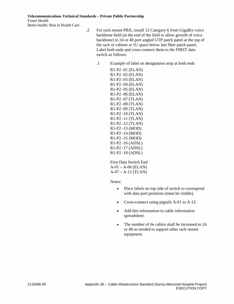
.2 For rack mount PBX, install 12 Category 6 from GigaBix voice backbone field (at the end of the field to allow growth of voice backbone) to 24 or 48 port angled UTP patch panel at the top of the rack or cabinet at 1U space below last fiber patch panel. Label both ends and cross-connect them to the FIRST data switch as follows:
.1 Example of label on designation strip at both ends R1-P2 -01 (ELAN) R1-P2 -02 (ELAN) R1-P2 -03 (ELAN) R1-P2 -04 (ELAN) R1-P2 -05 (ELAN) R1-P2 -06 (ELAN) R1-P2 -07 (TLAN) R1-P2 -08 (TLAN) R1-P2 -09 (TLAN) R1-P2 -10 (TLAN) R1-P2 -11 (TLAN) R1-P2 -12 (TLAN) R1-P2 -13 (MOD) R1-P2 -14 (MOD) R1-P2 -15 (MOD) R1-P2 -16 (ADSL) R1-P2 -17 (ADSL) R1-P2 -18 (ADSL) First Data Switch End A-01 – A-06 (ELAN) A-07 – A-12 (TLAN) Notes:
• Place labels on top side of switch to correspond with data port positions (must be visible).
• Cross-connect using pigtails A-01 to A-12.
• Add this information to cable information spreadsheet.
• The number of tie cables shall be increased to 24 or 48 as needed to support other rack mount equipment.

Telecommunications Technical Standards – Private Public Partnership Fraser Health Better health. Best in Health Care.
2116486.09 Appendix 3E – Cable Infrastructure Standard (Surrey Memorial Hospital Project) EXECUTION COPY
1.2.3.7. The supply and installation of the jumper wire between the demarcation and the tie or riser cables will be supplied and installed by the service provider.
1.2.3.8. All intercom riser cables shall terminate on IDC blocks adjacent to the intercom service for the facility and on IDC blocks at the telecommunications closets.
1.2.3.9. All data, intercom, and voice jacks shall be the same colour (black). Where Cat6 is used under special applications, the jack colour shall be purple.
1.2.3.10. All wall-mounted coverplates shall be 4 port single gang Belden Interface wall plates or the Authority approved equivalent.
1.2.3.11. All cables routed in modular furniture shall be terminated on 4 port MDVO Modular Furniture Adapter jacks mounted on manufacturer’s adapter plates anchored to the modular furniture. The Adapter snaps directly on industry standard 70 mm x 35 mm cutout in the adapter plate. Adapter part number is BeldenCDT AX10092 series. Adapter colour shall be the same as the adapter plate. Coordinate locations and type during detailed design.
1.2.3.12. All jacks at the work area shall be wired as information outlets. The plans shall include an alphanumeric character adjacent to the symbol defining the communication systems. The following characters shall be used to distinguish which systems are cabled to that location: • “I” intercom • “T” telephone • “D” data. A number shall also be placed adjacent to the above character to identify the number of cables and jacks per system to be run to that location. The number before forward slash refers to voice jack. The number after forward slash refers to data jacks (see drawing NS-01). When the total number of jacks and cables identified is less than four, install blank insert over the spare port. NOTE the jacks shall be located on the adapter plates and cover plates as per Figure 3.
1.2.3.13. Jack placement in the cover plate shall be as follows • Voice Left or Upper left • Data Right or upper right • Intercom Middle or lower left
Telecommunications Technical Standards – Private Public Partnership Fraser Health Better health. Best in Health Care.
2116486.09 Appendix 3E – Cable Infrastructure Standard (Surrey Memorial Hospital Project) EXECUTION COPY
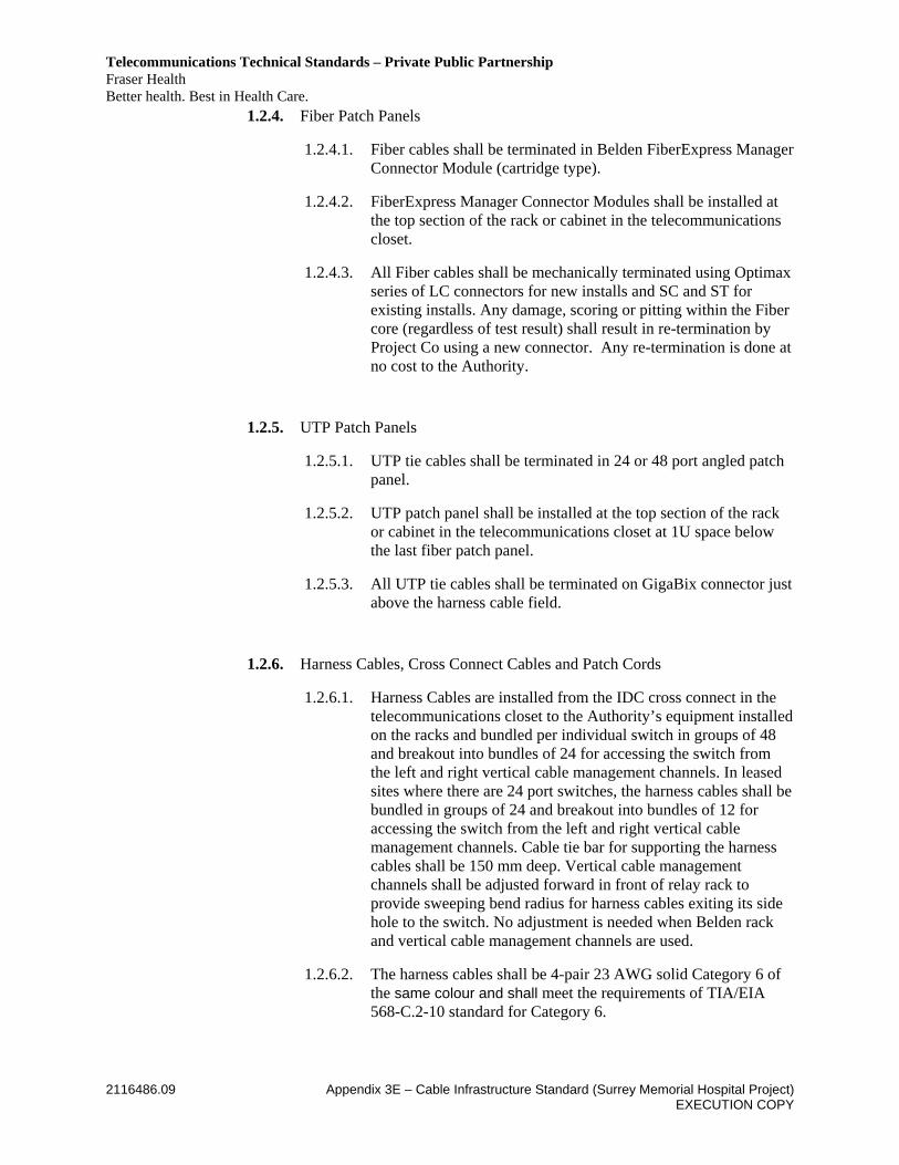
1.2.4. Fiber Patch Panels
1.2.4.1. Fiber cables shall be terminated in Belden FiberExpress Manager Connector Module (cartridge type).
1.2.4.2. FiberExpress Manager Connector Modules shall be installed at the top section of the rack or cabinet in the telecommunications closet.
1.2.4.3. All Fiber cables shall be mechanically terminated using Optimax series of LC connectors for new installs and SC and ST for existing installs. Any damage, scoring or pitting within the Fiber core (regardless of test result) shall result in re-termination by Project Co using a new connector. Any re-termination is done at no cost to the Authority.
1.2.5. UTP Patch Panels
1.2.5.1. UTP tie cables shall be terminated in 24 or 48 port angled patch panel.
1.2.5.2. UTP patch panel shall be installed at the top section of the rack or cabinet in the telecommunications closet at 1U space below the last fiber patch panel.
1.2.5.3. All UTP tie cables shall be terminated on GigaBix connector just above the harness cable field.
1.2.6. Harness Cables, Cross Connect Cables and Patch Cords
1.2.6.1. Harness Cables are installed from the IDC cross connect in the telecommunications closet to the Authority’s equipment installed on the racks and bundled per individual switch in groups of 48 and breakout into bundles of 24 for accessing the switch from the left and right vertical cable management channels. In leased sites where there are 24 port switches, the harness cables shall be bundled in groups of 24 and breakout into bundles of 12 for accessing the switch from the left and right vertical cable management channels. Cable tie bar for supporting the harness cables shall be 150 mm deep. Vertical cable management channels shall be adjusted forward in front of relay rack to provide sweeping bend radius for harness cables exiting its side hole to the switch. No adjustment is needed when Belden rack and vertical cable management channels are used.
1.2.6.2. The harness cables shall be 4-pair 23 AWG solid Category 6 of the same colour and shall meet the requirements of TIA/EIA 568-C.2-10 standard for Category 6.
Telecommunications Technical Standards – Private Public Partnership Fraser Health Better health. Best in Health Care.
2116486.09 Appendix 3E – Cable Infrastructure Standard (Surrey Memorial Hospital Project) EXECUTION COPY
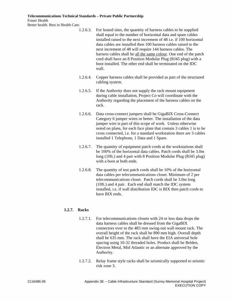
1.2.6.3. For leased sites, the quantity of harness cables to be supplied shall equal to the number of horizontal data and spare cables installed raised to the next increment of 48 i.e. if 100 horizontal data cables are installed then 100 harness cables raised to the next increment of 48 will require 144 harness cables. The harness cables shall be all the same colour. One end of the patch cord shall have an 8 Position Modular Plug (RJ45 plug) with a boot installed. The other end shall be terminated on the IDC wall.
1.2.6.4. Copper harness cables shall be provided as part of the structured cabling system.
1.2.6.5. If the Authority does not supply the rack mount equipment during cable installation, Project Co will coordinate with the Authority regarding the placement of the harness cables on the rack.
1.2.6.6. Data cross-connect jumpers shall be GigaBIX Cross-Connect Category 6 jumper wires or better. The installation of the data jumper wire is part of this scope of work. Unless otherwise noted on plans, for each face plate that contain 3 cables 1 is to be cross connected, i.e. for a standard workstation there are 3 cables installed 1 Telephone, 1 Data and 1 Spare.
1.2.6.7. The quantity of equipment patch cords at the workstations shall be 100% of the horizontal data cables. Patch cords shall be 3.0m long (10ft.) and 4 pair with 8 Position Modular Plug (RJ45 plug) with a boot at both ends.
1.2.6.8. The quantity of test patch cords shall be 10% of the horizontal data cables per telecommunications closet. Minimum of 2 per telecommunications closet. Patch cords shall be 3.0m long (10ft.) and 4 pair. Each end shall match the IDC system installed, i.e. if wall distribution IDC is BIX then patch cords to have BIX ends.
1.2.7. Racks
1.2.7.1. For telecommunications closets with 24 or less data drops the data harness cables shall be dressed from the GigaBIX connectors over to the 483 mm swing-out wall mount rack. The overall height of the rack shall be 890 mm high. Overall depth shall be 635 mm. The rack shall have the EIA universal hole spacing using 10-32 threaded holes. Product shall be Belden, Electron Metal, Mid Atlantic or an alternate approved by the Authority.
1.2.7.2. Relay frame style racks shall be seismically supported to seismic risk zone 3.

Telecommunications Technical Standards – Private Public Partnership Fraser Health Better health. Best in Health Care.
2116486.09 Appendix 3E – Cable Infrastructure Standard (Surrey Memorial Hospital Project) EXECUTION COPY
1.2.7.3. For telecommunications closets with more than 24 data drops the data harness cables shall be dressed from the GigaBIX connectors over to a 483 mm relay frame style rack. Provide 1 relay style rack for every 1632 horizontal data cables. The overall height of the rack shall be 2134 mm high with at least 44 rack units. The rack shall have the EIA universal hole spacing using 10-32 threaded holes. The relay frames shall be complete with universal vertical channels (top to bottom) having hinged covers, for vertical cable management, on both sides.
1.2.8. Cable Management in Telecommunications Closets
1.2.8.1. Provide all cable management as required.
1.2.8.2. Install cable management on hinged side of wall mount racks. Provide 4 D rings for vertical cable management on the hinged side of the wall frame.
1.2.8.3. The horizontal cable managers in the telecommunications closet for the wall mounted IDC terminations shall consist of D rings, cable managers, spaced as per manufacturer’s recommendation.
1.2.8.4. The horizontal cable manager on the rack for the harness cables shall be rack mount 6” deep cable tie bar.
1.2.9. CATV System
1.2.9.1. Each CATV outlet shall be cabled with a braided copper shielded RG6 cable terminated on an F series connector. The cover plate shall have an F series bulkhead for the termination of the cable. Each cable shall be home run to the CATV distribution point in the serving LTC. The CATV distribution point in each LTC shall be home run to the CATV distribution point in the MTC with a RG11 cable. The CATV distribution point in the MTC shall be home run to the service entrance room with a 40 mm coaxial cable unless otherwise designed. Following star-wired structured cabling topology, the cable distance between any two termination points shall not exceed 90 m.
1.3. Design
The following definitions are provided to help clarify the planning requirements for each space. Telecommunications Closet - All horizontal and riser data/voice cabling for a given floor terminates in this closet. It includes the relay racks and network hubs for that floor. Data Equipment Room - Contains the servers and some network equipment.
Telecommunications Technical Standards – Private Public Partnership Fraser Health Better health. Best in Health Care.
2116486.09 Appendix 3E – Cable Infrastructure Standard (Surrey Memorial Hospital Project) EXECUTION COPY
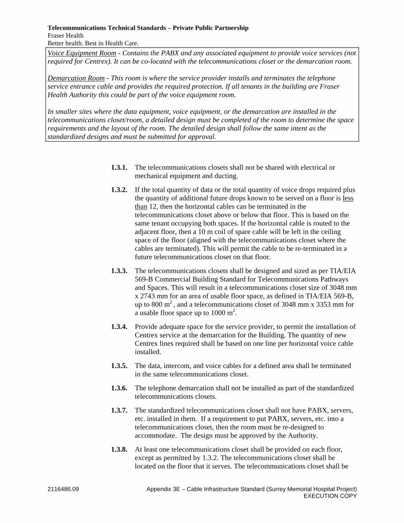
Voice Equipment Room - Contains the PABX and any associated equipment to provide voice services (not required for Centrex). It can be co-located with the telecommunications closet or the demarcation room. Demarcation Room - This room is where the service provider installs and terminates the telephone service entrance cable and provides the required protection. If all tenants in the building are Fraser Health Authority this could be part of the voice equipment room. In smaller sites where the data equipment, voice equipment, or the demarcation are installed in the telecommunications closet/room, a detailed design must be completed of the room to determine the space requirements and the layout of the room. The detailed design shall follow the same intent as the standardized designs and must be submitted for approval.
1.3.1. The telecommunications closets shall not be shared with electrical or mechanical equipment and ducting.
1.3.2. If the total quantity of data or the total quantity of voice drops required plus the quantity of additional future drops known to be served on a floor is less than 12, then the horizontal cables can be terminated in the telecommunications closet above or below that floor. This is based on the same tenant occupying both spaces. If the horizontal cable is routed to the adjacent floor, then a 10 m coil of spare cable will be left in the ceiling space of the floor (aligned with the telecommunications closet where the cables are terminated). This will permit the cable to be re-terminated in a future telecommunications closet on that floor.
1.3.3. The telecommunications closets shall be designed and sized as per TIA/EIA 569-B Commercial Building Standard for Telecommunications Pathways and Spaces. This will result in a telecommunications closet size of 3048 mm x 2743 mm for an area of usable floor space, as defined in TIA/EIA 569-B, up to 800 m2 , and a telecommunications closet of 3048 mm x 3353 mm for a usable floor space up to 1000 m2.
1.3.4. Provide adequate space for the service provider, to permit the installation of Centrex service at the demarcation for the Building. The quantity of new Centrex lines required shall be based on one line per horizontal voice cable installed.
1.3.5. The data, intercom, and voice cables for a defined area shall be terminated in the same telecommunications closet.
1.3.6. The telephone demarcation shall not be installed as part of the standardized telecommunications closets.
1.3.7. The standardized telecommunications closet shall not have PABX, servers, etc. installed in them. If a requirement to put PABX, servers, etc. into a telecommunications closet, then the room must be re-designed to accommodate. The design must be approved by the Authority.
1.3.8. At least one telecommunications closet shall be provided on each floor, except as permitted by 1.3.2. The telecommunications closet shall be located on the floor that it serves. The telecommunications closet shall be
Telecommunications Technical Standards – Private Public Partnership Fraser Health Better health. Best in Health Care.
2116486.09 Appendix 3E – Cable Infrastructure Standard (Surrey Memorial Hospital Project) EXECUTION COPY
located centrally on that floor, within the area it serves. The maximum horizontal cable length shall be less than 90 m. The telecommunications closets shall be vertically aligned.
1.3.9. The maximum area to be served from one telecommunications closet is 1000 m² (10, 765 ft²).
1.3.10. Additional telecommunications closets shall be provided when:
.1 Usable floor area to be served is greater than 1000 m² (10,000 ft²).
.2 Horizontal cable length required to reach the work area is greater than 90 m (295 ft²).
1.3.11. Multiple telecommunications closets on the same floor shall be interconnected with cable tray or at least one 3” conduit.
1.3.12. The telecommunications closet shall be accessible from a corridor with 914 mm wide and 2000 mm high working clearance. Access to the telecommunications closet must be provided as to not interrupt normal business workflows and provision of healthcare services.
1.3.13. In small telecommunications closet that does not have forced ventilation, the door shall be provided with door grille at the top and at the bottom of the door. Where door is part of a fire separation, the door shall be provided with “Anemostat” fusible link louvre at the top and at the bottom of the door.
1.3.14. All walls in the telecommunications closets and the voice/data equipment rooms shall be covered with 19 mm G1S plywood backboard 2440 mm high, capable of supporting attached equipment. Stainless steel counter-sunk screws shall be used to secure the plywood to the walls. Plywood should be either fire rated plywood painted white or plywood covered with two coats of white fire retardant paint.
1.3.15. For telecommunications closets that support an area greater than 500 m², the cable termination wall shall be a 150 mm deep cavity BIX wall covered with 20 mm, G1S plywood surface, smooth on both sides. Cables shall be routed through the wall spaces and plywood openings to the back of GigaBIX mounts. Exact locations of openings shall be engineered to suit BIX frame layout.
1.3.16. The telecommunications closet shall not have a false ceiling (unless required to maintain the integrity of the ceiling plenum). If codes permit the door shall swing 180º out and be lockable. If the door must swing in then the telecommunications closet shall be redesigned to accommodate lost area from door swing-in.
1.3.17. Wall, floor and ceiling finishes shall be light in colour to enhance closet lighting. All telecommunications closet floor coverings shall be anti-static linoleum composite sheeting. Vinyl tiles are not acceptable.
1.3.18. Walls shall be full height to the underside of the above floor slab. Where this is not possible, the height of the closet ceiling shall be higher than the
Telecommunications Technical Standards – Private Public Partnership Fraser Health Better health. Best in Health Care.
2116486.09 Appendix 3E – Cable Infrastructure Standard (Surrey Memorial Hospital Project) EXECUTION COPY
height of the hallway ceiling, and the distance between the top of the entry hallway tray and the closet ceiling shall maintain a clearance of 600 mm.
1.3.19. Penetrations through fire-rated walls, floors and ceilings shall be fire-stopped using products that are easily removable for future cable installations.
1.3.20. Lighting fixtures shall be mounted at a minimum of 2.8 M AFF.
1.3.21. Mesh type tray (Cablofil or Flextray) shall be provided around the perimeter of the Closet and across and over relay racks and server cabinets. The tray shall be mounted @ 2.7 M AFF.
1.3.22. A minimum of one equipment rack shall be supplied and installed in each telecommunications closet. The layout of the equipment in the rack and the exact placement of the racks, cable tray and termination fields shall be submitted for reviewed by the Authority.
.1 Each equipment rack shall be plumbed and leveled, and solidly bolted to the floor with bolts, washers and brackets. Bonding of rack to ground shall be as per TIA/EIA J-STD-607A.
.2 Where two or more racks are mounted side by side, they shall be bolted together with a vertical cable management channel in between using metal bolts and washers.
.3 Access clearance of 1 m in the front and 750 mm at the rear of equipment racks is mandatory. Access clearance of 1 m at the rear of server cabinets is mandatory. Supply APC server cabinets complete with anchoring brackets where required. Where several rows of racks are located side by side, the spacing between the rows shall be a minimum of 1 m. A minimum clearance of 150 mm shall be maintained between one side of an equipment rack and the wall.
1.3.23. Conduit penetration into the telecommunications closet at ceiling height shall protrude no more than 50 mm without a bend and be above 2.7 M AFF to clear ceiling tray.
1.3.24. Smoke Detector, Heat Detector, Sprinkler System
.1 Cage shall be provided to sprinkler heads for mechanical protection.
.2 A drip tray shall be installed if sprinkler head is located above Telecommunications equipment rack.
1.3.25. Power supply for equipment racks shall be on or nearby each equipment rack. For larger rooms requiring more than (1) rack, specific power requirements shall be determined in consultation with the Authority. The minimum requirement is:
a) If the standby power is supplied by a building UPS, Project Co shall provide a minimum of (2) 20A 120V single phase circuits, each terminated in separate box using NEMA L5-20R receptacles. The

Telecommunications Technical Standards – Private Public Partnership Fraser Health Better health. Best in Health Care.
2116486.09 Appendix 3E – Cable Infrastructure Standard (Surrey Memorial Hospital Project) EXECUTION COPY
power bars (2) to be provided by Division 16 for this configuration shall be APC part# AP7530 or an acceptable equivalent.
b) If the standby power is supplied by motor-generator or there is no standby power available, Project Co shall provide a minimum of (1) 30A 120V circuit terminated in separate box using a NEMA L5-30R receptacle. (The Authority supplied UPS of choice for this configuration is an APC Smart-UPS 3000VA part # SUA3000RM2U). The power bars (2) to be provided by Division 16 for this configuration shall be RFM-62-PBV-24 or an equivalent approved by the Authority.
c) Provide adequate power for all wall mounted equipment, in consultation with the Authority.
1.3.26. Project Co shall provide (2) dedicated 15A 120V circuits in double gang duplex convenience outlets located at not more than 1830mm (6 ft) intervals around the perimeter walls of the telecommunications closets.
1.3.27. The HVAC serving the telecommunications closet and equipment rooms shall be designed to maintain a temperature between 18-24º C with a relative humidity between 30 and 55 percent. The HVAC system shall be designed to maintain these requirements 7x24 hour operation. Detailed heat load shall be calculated at time of design.
1.3.28. The room will have its own-switched lighting.
1.3.29. Entrance Cable Protectors .1 Leave wall space for entrance facility terminations and protectors in
entrance facility room of the Building. In cases where entrance facility room does not exist, the entrance requirements apply to the MTC.
1.3.30. Demarcation Requirements
.1 For protection against network downtime, Project Co shall identify and provide redundant physical routing that provides the most protection by placing outside plant fibers and coppers in a second physical route to immediately take over if the cable is damaged.
.2 Project Co shall coordinate with the service provider regarding entrance cable requirements and support facilities.
.3 Project Co shall install the appropriate cable types from all service provider demarcation points to the Authority’s MTC.
.4 Project Co shall coordinate with the service provider for the required connector types. For Telus’ singlemode entrance cable, SC connector type is specified.
.5 Singlemode and multimode fibre from the existing data core in the South Building will be terminated in the MTC in the Building in 4U FiberExpress Manager patch panel at the top of the floor mount rack, complete with FiberExpress Manager connector modules in LC

Telecommunications Technical Standards – Private Public Partnership Fraser Health Better health. Best in Health Care.
2116486.09 Appendix 3E – Cable Infrastructure Standard (Surrey Memorial Hospital Project) EXECUTION COPY
connectors. Terminate in the data core in the South Building in an existing fibre rack in 4U FiberExpress Manager patch panel below the existing switches complete with FiberExpress Manager connector modules on LC connectors.
.6 Provide all necessary FiberExpress Manager hardware.
1.3.31. Project Co shall request and coordinate with the Authority inspection of the cabling system during the Construction, including at the following stages:
.1 cable rough-in;
.2 telecommunications closet construction;
.3 testing; and
.4 completion.
1.3.32. Wireless Design .1 TSB-162 provides guidelines for pre-cabling a building using a grid
approach. The pre-cabled grid makes the building ready for a wireless infrastructure at any time simply by plugging into a wireless access point. The square cell structure helps designers determine approximately where APs will be located for seamless wireless coverage resulting in an upfront approximation of how many APs and how much cabling will be required for the WLAN.
.2 A grid is a collection of uniform cells where each cell is a square.
.3 The size for a square is 10.0 m x 10.0 m for seamless wireless access point coverage for both 5 Ghz frequency range (802.11a) and 2.4 GHz (IEEE 802.11b/g).
.4 The size of the cell and the number of required wireless access points per cell will depend on coverage, bandwidth, types of applications, network usage patterns, quality of service and number of users.
.5 The wireless outlet is located at the center of the square cell, either above or below the drop ceiling.
a. This allows the flexibility to move the access point anywhere within the square using patch cord that is up to 0.707 times X in length, where X is the length of a side of the square. For X equal to 16m, the maximum length of the patch cord is 11.8m. The maximum length of the patch cord allowed is 13.0m.
.6 Power will be delivered through the horizontal cabling utilizing IEEE 802.3af complaint equipment at both ends. This eliminates need to install local power outlet within vicinity of the wireless access point.
.7 IEEE 802.11g standard for wireless local area networks offers transmission over short distances at theoretical maximum of 54
Telecommunications Technical Standards – Private Public Partnership Fraser Health Better health. Best in Health Care.
2116486.09 Appendix 3E – Cable Infrastructure Standard (Surrey Memorial Hospital Project) EXECUTION COPY
megabits per second (Mb/s). Effective data throughput for each wireless access points in an indoor office environment are as follows:
a. 20-22 Mb/s for distances of 15 m to 18 m.
b. 15-20 Mb/s for distances of 18 m to 21 m.
c. 10-15 Mb/s for distances of 21 m to 24 m.
d. 5-10 Mb/s for distances of 24 m to 36 m.
e. Dividing the data throughput value by the maximum number of stations expected to associate with the wireless access point provides the estimated throughput for each workstation.
f. These ranges are consistent with recommended cell size in TSB-162.
.8 An RF assessment with spectrum analyzer is required to determine the suitability of a 2.4 GHz (IEEE 802.11b/g) or 5 GHz (IEEE 802.11a) WLAN operations in the environment on a channel by channel basis and to ensure a minimum signal to noise ratio of 20 dB is available at all potential WLAN device locations. The RF planner shall determine exact cell size and placement of the AP based on site survey of signal strength capacity, and roaming in attempts to meet bandwidth and user requirements, and to provide seamless coverage as users move around an area.
1.3.33. Wireless Installation .1 One wireless access point is required for every 10.0m x 10.0m for
seamless coverage, regardless of the type of material within the building.
.2 Regardless of the location and mounting method of the wireless access point, the following installation parameters must be met:
a. Two - 100 ohms UTP Category 6 or higher cables shall be installed to each wireless outlet. Terminate 2 x Category 6 cables on Belden jack and 4 port single gang Interface plate on 4” x 4” outlet box with a single gang mud ring. Four-fiber multimode optical fiber cables may also be installed.
b. The horizontal cable length from the serving telecommunications closet to the outlet shall not exceed 80m.
c. Two - 100 ohms UTP Category 6 or higher patch cords shall be plugged into each wireless outlet. The maximum length of the patch cord allowed is 13m. They shall be coiled and supported at the wireless outlet location. The use of a patch cord between the
Telecommunications Technical Standards – Private Public Partnership Fraser Health Better health. Best in Health Care.
2116486.09 Appendix 3E – Cable Infrastructure Standard (Surrey Memorial Hospital Project) EXECUTION COPY
telecommunications outlet and the AP enables moving the AP around within the cell for specialized coverage.
d. Wireless access points shall not be located less than 3.6m from finished floor. Below this level, an enclosure must be used if the environment is considered insecure.
e. Mounting arrangements include wall-mount above drop ceiling, wall-mount below drop ceiling and in-the-grid ceiling mount.
f. The method of mounting the outlet shall suit the level of security at each location.
g. Administrative areas with high human traffic do not require taking high security measures.
h. Hallways that are not patrolled or monitored are considered highly insecure environments and must have the appropriate high security measures applied.
i. Classrooms, lecture theatres, patient and staff lounges or any other insecure environments must have the appropriate high security measures applied.
j. Locate, mount and provide grounding, type of service cable and enclosures for outdoor wireless access points in accordance with the applicable CEC and BC Building Code requirements.
1.4. Documentation / Labeling
1.4.1. Distribution terminals shall use standard TIA/EIA colour coding on all terminations as follows: Green = Termination of network connection on the customer side of the demarcation point White/Silver = Termination of cables originating from common equipment (PBXs, computers, LANs and multiplexers). Brown = Interbuilding backbone. Purple = First-level backbone. Riser/backbone and between equipment rooms. Blue = Stations served directly from closets, i.e. horizontal wiring. Gray = Second-level backbone.
1.4.2. Faceplate Work Area (Fig. 3&4)
1.4.2.1. Faceplates shall have the following labels:
.1 Telecommunications closet ID# Top of plate. Brother P Touch or an equivalent approved by the Authority.

Telecommunications Technical Standards – Private Public Partnership Fraser Health Better health. Best in Health Care.
2116486.09 Appendix 3E – Cable Infrastructure Standard (Surrey Memorial Hospital Project) EXECUTION COPY
.2 Telecommunications closet Architectural room # Bottom of Plate. Brother P Touch or an equivalent approved by the Authority.
.3 Jack # directly above or below jack. Brother P Touch or an equivalent approved by the Authority.
1.4.3. Telecommunications Closets 1.4.3.1 MTC / LTC (Main Telecommunications Closet / Local
Telecommunications Closet) Terminal ID Assignments All telecommunications closets shall have unique alpha numeric terminal numbers assigned, example - “SBBL-01A”. The numbers and not the background shall be 50 mm high engraved on lamacoid in permanent Blue on Yellow background. It shall be placed on a visible location at the top of the GigaBix wall whenever feasible and secured by screws at four corners. Project Co will label telecommunications closets in consultation with the Authority and in accordance with the following example.
.1 B1A shall start at basement level – representing 1st telecommunications closet.
.2 01A shall be 1st floor level – representing 1st telecommunications closet.
.3 02A shall be 2nd floor level – representing 1st telecommunications closet.
.4 03A shall be 3rd floor level – representing 1st telecommunications closet.
.5 03B would then be 3rd floor level – representing 2nd telecommunications closet.
Label the MTC with the appropriate floor number and the letter A. Then assign letters B, C etc. to the telecommunications closets on the same floor starting at the MTC and moving counterclockwise. On each successive floor, label the telecommunications closet located directly above the MTC with the letter A and then label the remaining telecommunications closets on that floor accordingly.
1.4.4. UTP Horizontal Cabling (Fig. 3&4)
.1 Horizontal UTP cable terminations in the telecommunications closet on GigaBIX block shall be typewritten on blue labels and be sequentially numbered.
.2 Voice and data horizontal cables shall be identified at each termination end with a unique number at the outlet jack and at the GigaBIX designation strip.
Telecommunications Technical Standards – Private Public Partnership Fraser Health Better health. Best in Health Care.
2116486.09 Appendix 3E – Cable Infrastructure Standard (Surrey Memorial Hospital Project) EXECUTION COPY
i.e. BBBB-01A-H052 BBBB Represents the Building Code 01A Represents 1st floor, telecommunications closet H052 Represents jack unique ID and cable position on GigaBIX termination field.
(WP) Represents wireless point labeled after unique cable ID.
.3 Horizontal UTP cable numbering at each end of the cable sheath shall be identical to the associated jack number with the format “BBBB-01A-CXXX” i.e. BBBB-01A-C052 BBBB Represents the Building Code. 01A Represents 1st floor, telecommunications closet. C Represents Cable. 052 Represents jack unique ID and cable position on GigaBIX termination field.
.4 All data horizontal cables shall be cross connected at the GigaBIX fields and patched to the switch location on rack with harness cables (cable between the rack mounted equipment and GigaBIX block).
1.4.5. Harness Cables (Fig. 3&4) Harness cables numbering at each end of the cable sheath shall be typed
written on white labels and be sequentially numbered with the format R1-X-01 to 48.
i.e. R1-G01. Cable code for Archibus use only: BBBB-01A-R1-G01.
R1 Fist Rack in closet or equipment room
G Is the 7th group of harness cables. The lettering sequence is from top to bottom of rack.
01 Represents the port on the equipment
1.4.6. Patch Panel Tie Cables Patch panel tie cable numbering at each end of the cable sheath shall be typed written on white labels and be sequentially numbered with the format R1-P1-01 to 48. They shall be terminated on GigaBix connector just above the harness cable field.
i.e. R1-P1-01. Cable code for Archibus use only: BBBB-01A-R1-P1-01.
R1 Fist Rack in closet or equipment room
P1 Is the 1st UTP patch panel in the rack. The lettering sequence is from top to bottom of rack.

Telecommunications Technical Standards – Private Public Partnership Fraser Health Better health. Best in Health Care.
2116486.09 Appendix 3E – Cable Infrastructure Standard (Surrey Memorial Hospital Project) EXECUTION COPY
01 Represents the port on the patch panel
1.4.7. Backbone Cabling
1.4.7.1. Data Copper
.1 Where more GigaBIX blocks are required for Backbone (riser) or PBX cabling, additional columns of GigaBIX blocks shall be added to the wall termination field. The additional wall space required shall be reflected in the design layout of the telecommunications closet.
.2 If Project Co installs Category 5e UTP cables in the Backbone, these cables shall be grouped in incremental counts of six and identified on each end of the cable with a label. The associated GigaBIX designation strip at each end shall be identified with a purple label. NOTE: Where the quantity of Backbone data cables required is small, the cables shall be grouped and terminated onto the same GigaBIX block as voice. Voice field shall populate upper half of the block and data the lower half.
i.e. BBBB-01A/BBBB-02B-D1 to D6. Cable code for Archibus use only: BBBB-01A/02B-D1. BBBB Represents the Building Code
01A Represents from 1st floor telecommunications closet A, Backbone GigaBIX.
02B Represents to 2nd floor telecommunications closet B, Backbone GigaBIX.
D1 Represents Backbone data cable unique ID (individual 4 pair cable).
1.4.7.2. Voice Copper Backbone
.1 If Project Co installs Category 5E UTP cables in the Backbone (riser) from MTC to each of the LTC’s, these Backbone cables shall be identified at both ends and on the GIGABIX designation strips. Minimum number of cable pairs between any 2 points shall be 50.
.2 On the GigaBIX designation strip in the telecommunications closet, the Backbone cable numbering shall appear sequentially starting at “001” at the top left-hand corner of
Telecommunications Technical Standards – Private Public Partnership Fraser Health Better health. Best in Health Care.
2116486.09 Appendix 3E – Cable Infrastructure Standard (Surrey Memorial Hospital Project) EXECUTION COPY
the first Backbone GigaBIX block. Next mount shall continue the sequence if required. i.e. BBBB-01A/BBBB-02B-V1(1-50). Cable code for
Archibus use only: BBBB-01A/02B-V1. BBBB Represents the Building Code
01A Represents from 1st floor telecommunications closet A, Backbone GigaBIX.
02B Represents to 2nd floor telecommunications closet B, Backbone GigaBIX.
V1 Represents 1st group (sheath) of voice cables.
(1-50) Represents number of pairs inside cable sheath.
1.4.7.3. Fiber .1 Intra-building Backbone (riser) fiber optic cables from
MTC to each of the LTC’s, shall be labeled at each end within 6 cm from end of cable sheath with permanent self-adhesive label with minimum 3 mm high characters. Cable numbering shall have the format “BBBB-01AR1P1/BBBB-02BR1P1-F1(cable type)”.
i.e. BBBB-01AR1P1/BBBB-02BR1P1-F1(cable type). Cable code for Archibus use only: BBBB-01A/02B-F1. BBBB Represents the Building
01AR1P1 Represents from 1st floor telecommunications closet A, Rack 1, FiberExpress Panel 1.
02BR1P1 Represents to 2nd floor telecommunications closet B, Rack 1, FiberExpress Panel 1.
F1 Represents Fiber optic cable #1.
(cable type) Represents (12 SM) and/or (12 – 50MM10G, 50MM1G, 62.5MM).
Telecommunications Technical Standards – Private Public Partnership Fraser Health Better health. Best in Health Care.
2116486.09 Appendix 3E – Cable Infrastructure Standard (Surrey Memorial Hospital Project) EXECUTION COPY
1.4.8. Entrance Cable
1.4.8.1. Fiber .1 Inter-building Backbone (entrance) fiber optic cables
shall be labeled at each end within 6 cm from end of cable sheath with permanent self-adhesive label with minimum 3 mm high characters. Cable numbering shall have the format “RMH-01A/MRM-01B-F1 (cable type)”. Cable code for Archibus use only: RMH01AMRM01BF1.
.1 RMH-01A represents abbreviated building name (Ridge Meadow Hospital), 1st floor telecommunications closet A.
.2 MRM-01B represents abbreviated building name (Maple Ridge Medical), 1st floor telecommunications closet B.
.3 F1 represents Fiber optic cable #1. .4 (cable type) represents (12 SM) and/or (12 –
50MM10G).
1.4.8.2. Voice Copper .1 Inter-building Backbone (entrance) copper cables shall
be labeled at each end within 6 cm from end of cable sheath with permanent self-adhesive label with minimum 3 mm high characters. Cable numbering shall have the format “SBAL-01A/SBBL-01B-V1 (cable pairs)”. Cable code for Archibus use only: SBAL01ASBBL01BV1.
.1 SBAL-01A represents abbreviated building name, 1st floor telecommunications closet A.
.2 SBAL-01B represents abbreviated building name, 1st floor telecommunications closet B.
.3 V1 represents voice copper cable #1. .4 (cable pairs) example - (1-50), (1-100), (1-200), etc.
1.4.9. All electrical equipment and receptacle cover plates shall be identified by means of black lamicoid labels c/w minimum 3/8” white lettering; labels shall indicate panel name and circuit numbers.
Telecommunications Technical Standards – Private Public Partnership Fraser Health Better health. Best in Health Care.
2116486.09 Appendix 3E – Cable Infrastructure Standard (Surrey Memorial Hospital Project) EXECUTION COPY
1.4.10. The IDC blocks at the demarcation and the IDC output from the PABX, if used, should be labeled with the unique pair number and destination closet. The labeling shall also be provided at the input and output terminations for the PABX, if a PABX is being installed. Use manufacturer’s labels with sequential pair number neatly printed on the label, and the appropriate colour coding as previously identified (white/silver).
1.4.11. Project Co shall complete cable information spreadsheet provided by the Authority in Excel forma (refer to Attachment 1 to this Appendix). Provide a hard (binder) and soft copy of the completed spreadsheet to the Authority and mount one printed copy of the completed form on the interior side of the door of each telecommunications closet in a transparent plastic pocket.
1.4.12. “As Built” drawings shall conform to the Authority’s AutoCAD drawing template layers and Standards Symbols (refer to FH-Facilities Planning). Project Co shall forward these “As Built” drawings to the Authority in hardcopy and in electronic form. A copy of the “As Built” drawing showing the jack numbers associated with that specific telecommunications closet shall be mounted on the interior side of the door of that telecommunications closet in a transparent plastic pocket holder.
1.4.13. The “As Built” drawings shall show all telecommunications jacks and the associated label for each jack. The drawing legend shall be shown on each page. The drawings shall also show any cable tray and major conduit that are used for the telecommunications system, and all telecommunications closets with label ID. The “As Built” drawings shall include a riser diagram showing all data, intercom, and voice riser cables.
1.5. Installation
1.5.1. Installation shall follow the standardized telecommunications closet designs and TIA/EIA standards.
1.5.2. The installation shall meet the requirements of industry practices as recommended by the manufacturer whose products are being installed, and the TIA/EIA Standards (except where this Technical Standard differs). The Installation shall also meet the BICSI Telecommunications Cabling Installation Manual.
1.5.3. Install cable from the wall outlet to the telecommunications closet serving that area. The cables shall be continuous. Terminate the cable on the appropriate termination hardware.
1.5.4. Installation and terminate the 4 pair harness cables from the IDC terminations to the Authority’s equipment on the rack and install the associated jumper wire to complete the data cross connection. In acute sites, one horizontal data cable per outlet shall be cross connected to the switch. In community sites, one horizontal data cable and one horizontal spare cable shall be cross connected to the switch.
1.5.5. All horizontal cables shall be terminated in the work area. No cables shall remain unterminated in the ceiling space.

Telecommunications Technical Standards – Private Public Partnership Fraser Health Better health. Best in Health Care.
2116486.09 Appendix 3E – Cable Infrastructure Standard (Surrey Memorial Hospital Project) EXECUTION COPY
1.5.6. Walls shall have102 mm x 102 mm outlet boxes installed with a single gang mud ring. Outlets shall not be installed back-to-back inside the wall. A minimum 150 mm horizontal clearance shall be maintained between the two. All outlets shall be positioned to clear millwork and furniture and to enable easy and unobstructed access. A 19 mm conduit shall be installed from the outlet box to the ceiling space. The conduit shall have a grounding bushing installed in the ceiling space and be installed such that the minimum bend radius of the cable is not exceeded. If the wall is an existing internal partition with no insulation then a low voltage mounting bracket with open wiring is acceptable providing a grommet is used at all stud/plate penetrations. • Conduit shall be EMT or rigid steel.
• Flexible metallic and PVC conduit shall not be used in pour concrete unless specified.
• All conduits shall have sweeping bends with inside radius of no less than six times the internal diameter of the conduit. For conduit 50mm or larger, the radius shall be no less than ten times the internal conduit diameter. Fittings such as LB type joints shall not be used.
• Conduits shall be attached to the edge of cable tray with a conduit bracket designed for this purpose. If this is not possible, conduit shall be stubbed within 150 mm above the tray and terminate in a bonding type bushing.
• Where conduits are mounted high above cable tray, 90º bends for conduits shall be provided with conduit ends stubbed 150 mm above the tray in a bonding type bushing. This water fall effect shall reduce the strain on cables.
• When installing cable in conduit, cable fill shall not exceed 40% fill ratio where there are zero bends in the raceway, and not to exceed 28% where there are two 90º bends in the run.
• A pull tape shall be left in all raceways after installation of the cables. Pull tape shall be Greenlee 4435 or approved equal.
• All empty raceway shall be clearly and permanently marked at both ends to indicate destination and function.
• Conduits and cables containing line voltage conductors (including branch circuit wiring) shall not be supported from the supports used for Telecommunications cable trays or from the trays themselves.
• When zone conduit system is used, connect the system to each room ceiling space entered with a minimum 300 mm X 300 mm X 150 mm deep pull-box. Conduits to outlets in the room shall be from this pull-box.
Telecommunications Technical Standards – Private Public Partnership Fraser Health Better health. Best in Health Care.
2116486.09 Appendix 3E – Cable Infrastructure Standard (Surrey Memorial Hospital Project) EXECUTION COPY
• When zone conduit system is not installed in readily accessible false ceiling space, access hatches shall be installed at a nominal spacing of 9m.
• Conduits shall be installed inside the wall.
• Conduits, fittings and duct sleeves shall be installed prior to pouring of concrete. They shall be placed neatly following building grid lines and close to building structure to keep furring to a minimum.
1.5.7. Surface Raceway • Multi-outlet surface raceway shall be minimum 120 mm X 90 mm
deep with cut-outs and hardware for mounting faceplates.
• Where metallic raceway is required it shall be as manufactured by Wiremold. The colour shall match existing Wiremold installation.
• Non-metallic surface raceway shall be manufactured by Panduit or approved equal. Except as noted, colour of Panduit shall be off-white on painted surfaces and grey on unfinished concrete surfaces.
• Surface raceway extending into the ceiling shall connect to the conduit extending from the cable tray with the appropriate fitting or pull box.
• When installing cable in surface raceway, cable fill shall not exceed 40% fill ratio where there are zero bends in the raceway, and not to exceed 28% where there are two 90º bends in the run.
1.5.8. Pull Box • Unless specified otherwise, the minimum size of a pull box shall be
300 mm X 300 mm X 150 mm deep.
• In a zone conduit system, pull boxes shall be provided such that conduit length shall not exceed 9 m and the number of 90o bends shall not exceed two.
1.5.9. Maintain manufacturer’s recommended spacing from RF and EMI sources. Where such separation is not possible install the cables in grounded metallic conduit. • To avoid electromagnetic interference, the following minimum
clearances shall be maintained:
.1 1.2 m from large motors or transformers.
.2 300 mm from conduit and cables used for electrical power distribution.
.3 120 mm from fluorescent lighting.
Telecommunications Technical Standards – Private Public Partnership Fraser Health Better health. Best in Health Care.
2116486.09 Appendix 3E – Cable Infrastructure Standard (Surrey Memorial Hospital Project) EXECUTION COPY
• Pathways shall cross perpendicular to fluorescent lighting and electrical power cables or conduits.
1.5.10. Leave 305 mm of cable coiled in the outlet box (or coiled behind the wall if a low voltage mounting bracket is used) at the wall jack location.
1.5.11. If power poles are used leave 3 m of spare cable coiled in the ceiling space above the power pole to permit relocation of the power pole. Properly support cable coil to the structure.
1.5.12. If power poles use surface mount boxes, they shall be securely anchored to the pole using self-tapping screws. Use of self-adhesive pad alone is insufficient.
1.5.13. Avoid the use of infloor duct systems in concrete pours for data/voice cabling in all new buildings.
1.5.14. Cable installed in accessible ceilings shall be supported with open top cable supports (J hooks). The J-supports shall be located from 1220 mm to 1530 mm on centers to adequately support and distribute the cable’s weight. These types of supports may typically hold up to fifty 6.4 mm diameter cables. Suspended cables must be installed with at least 8 cm of clear vertical space above the ceiling tiles and support channels (T-bars). The maximum cable sag permitted is 305 mm. For large quantities of cables (>30) that converge at or near the telecommunications closet and other areas, provide cable trays or other special open supports that are specifically designed to support the required cable weight and volume. • In all retrofit situations, the type of cable tray shall match existing
installs. The new section of cable tray shall be connected to the existing cable tray. Existing tray end shall be re-worked to suit tie-in.
• For installation details of mesh type tray (Cablofil or Flextray) and EZ Path firestop device through fire rated wall, refer to drawing NS-11 in Attachment 1 to this Appendix.
• Mesh tray (min. 300mm wide) and drop outs shall be installed around the perimeter of the Closet and extend over equipment rack or rows of equipment racks. Drop-outs shall be installed where cables drop vertically to terminate on termination wall or to equipment racks. Do not cut tray for cable exit, instead use only Cablofil dropouts that attached to the tray side with dropouts hanging over the tray. Tray layout shall be confirmed with the Authority
• Perimeter tray in Telecommunications room shall be offset about 250mm from wall to tray edge to allow Cablofil dropouts to drop into GigaBix cable management modules. For large install using false wall, the offset maybe wider at about 350mm. Adjust on site to suit.
• Dropouts shall be provided when cables exit hallway cable tray.

Telecommunications Technical Standards – Private Public Partnership Fraser Health Better health. Best in Health Care.
2116486.09 Appendix 3E – Cable Infrastructure Standard (Surrey Memorial Hospital Project) EXECUTION COPY
1.5.15. Where horizontal cables pass though a fire separation wall, install sleeve to protect cables. Sleeve to be sized for no greater than 40% fill. Firestop sleeves once the cables are installed.
1.5.16. If the cables are installed in non-accessible ceilings the cables shall be installed in continuous conduit. The minimum size conduit shall be ¾”.
1.5.17. All cable shall be supported to the structure independent of the electrical/mechanical systems and the suspended ceiling.
1.5.18. All cables shall be installed parallel to the grid lines of the building.
1.5.19. Cabling shall be consolidated in building corridors to minimize disruption to occupants.
1.5.20. Install a minimum of three 102 mm sleeves in the floor to interconnect the telecommunications closets. The ducts shall be positioned against the wall to the left of the GigaBIX termination fields. These sleeves shall be used to distribute riser cables. Firestop sleeves once the cables are installed with an approved re-enterable sealing material. • For underground entrance ducts, the duct size shall be 100 mm. A
minimum of two 100 mm entrance ducts shall be installed. One duct shall be reserved as spare. Bends are not recommended; if required there should be no more than two 90º bends.
• Riser ducts in the telecommunications closets shall protrude 100 mm above finished floor level and shall be encased in concrete. The ducts shall protrude 50 mm below the floor slab into the ceiling space of the telecommunications closet below.
• If a telecommunications closet cannot be vertically aligned with the one above or below, or if it cannot be vertically aligned with the entrance facility Closet, a horizontal backbone pathway shall be used to connect them.
1.5.21. In telecommunications closets and other areas where cables will be bundled, use 25 mm Velcro straps to support/bundle the cables at 300 mm intervals. Provide 100% spare cable capacity in the Velcro straps. Tie wraps are not acceptable.
1.5.22. Grounding
1.5.22.1. Install grounding system as per ANSI/EIA/TIA 607A.
1.5.22.2. Install a complete grounding system to each telecommunications closet and bond all equipment. This shall include a ground bus in the telecommunications closets and the data/voice equipment rooms. Connect ground bus to system ground for the facility. • MTC: electrotin plated copper busbar – (TMGB), c/w two
50 mm insulated standoffs, with a minimum dimension of 100 mm wide X 300 mm long X 6 mm thick.
Telecommunications Technical Standards – Private Public Partnership Fraser Health Better health. Best in Health Care.
2116486.09 Appendix 3E – Cable Infrastructure Standard (Surrey Memorial Hospital Project) EXECUTION COPY
• LTC: electrotin plated copper busbar (TGB), c/w two 50 mm insulated standoffs, with a minimum dimension of 50 mm wide X 300 mm long X 6 mm thick.
• All busbars shall be pre-drilled with standard NEMA 10-32 bolt holes.
• Bonding conductors shall be identified at both ends with data plate cable marker complete with double straps to indicate where the destination end of the conductor is located, such as ‘Telecom Closet BBBB-01A’ or ’Entrance Rm 123’.
1.5.22.3. Bonding conductors shall be as short as possible and routed with a minimum of bends. All bends made on the conductor shall be sweeping bends.
1.5.22.4. Where practicable, all bonding conductors shall be installed without a splice. Where a splice is necessary, it should be accessible and located in a Telecommunications space. Conductors shall be spliced using irreversible compression-type connectors, exothermic welding, or equivalent. All joints shall be adequately supported and protected.
1.5.22.5. Bonding connections shall be made with bolts, crimp connectors, clamps, or lugs specifically designed for the purpose.
1.5.22.6. In equipment rooms with PBX equipment, supply a #6 insulated ground from the electrical panel supplying power to the PBX. Leave 3 m coil at location of PBX. Service provider will terminate ground at PBX.
1.5.23. The cabling system warranty shall be 25 years with liability of 2 times the installed parts cost.
1.5.24. POE Switch Traffic Load Distribution • In situations where two data cables per outlet are required to be cross
connected to POE switches, the network traffic load (PC and IP) shall be distributed evenly across all the switches, i.e. assuming four switches:
o From outlet #1, cross-connect first data port (PC) to switch #1 and cross-connect second data port (IP phone) to switch #2.
o From outlet #2, cross-connect 1st data port (PC) to switch #3 and cross-connect 2nd data port (IP phone) to switch #4.
o From outlet #3, cross-connect first data port (PC) to switch #2 and cross-connect second data port (IP phone) to switch #1.
Telecommunications Technical Standards – Private Public Partnership Fraser Health Better health. Best in Health Care.
2116486.09 Appendix 3E – Cable Infrastructure Standard (Surrey Memorial Hospital Project) EXECUTION COPY
o From outlet #4, cross-connect 1st data port (PC) to switch #4 and cross-connect 2nd data port (IP phone) to switch #3.
o This distribution method shall be repeated until all the data cables are cross-connected.
• Consulting Engineer shall advise IT on the number of data cables homerun to each closet for purpose of quantifying the number of switches required.
1.6. Testing
1.6.1. Category 6 UTP testing shall conform to current ANSI/ TIA/EIA – 568C.2-10 standard. Testing shall be accomplished using Fluke’s latest Digital Cable Analyzer field tester with GigaBIX channel adapters. Channel link testing procedures shall be used to certify the system. The latest Fluke Microcode Revision Upgrade shall be installed in all testers. NO SUBSTITUTE TESTERS WILL BE ALLOWED. The tester shall comply with the accuracy requirements for the level III field testers as defined in the TIA/EIA-568-C.2 Standard. It shall be calibrated within the calibration period recommended by the vendor.
1.6.2. After testing, Project Co shall supply to the Authority a complete set of UTP test results on CD format in addition to the required hard copy. NOTE: the Authority is using the Fluke Networks Link Ware software. NO other format will be accepted.
1.6.3. Test Category 5E Intra-building voice backbone cables and intercom riser cables to TIA/EIA-568-C.2 series.
1.6.4. Test all the installed twisted-pair horizontal links from the harness cable in the telecommunications closet to the equipment patch cord at the Telecommunications wall outlet against the “Channel Link” performance limits specification as defined in the TIA/EIA-568-C.2 series. For inter-building voice backbone cables using Category 3, test for continuity and polarity only; the test results need not be submitted but Project Co must sign off the test results indicating the testing has been completed and everything is acceptable.
1.6.5. 100% of the installed cabling links must be tested and must pass the requirements of TIA/EIA-568-C.2 Standard. Any failing link must be diagnosed and corrected.
1.6.6. After data switch is installed and ports cross-connected and activated, test each cable link with Fluke Tester (Intellitone) from patch cord to activated port to ensure the port is alive and ready to receive end device. Record test results on cable information spreadsheet.
1.6.7. Test each fiber strand using an optical power meter to ensure the actual power losses are less than the expected losses (calculated). Submit actual test results with calculated losses for review. For calculated losses use .3 dB per splice, .5 dB per connector pair, and the manufacturer’s published cable losses.
Telecommunications Technical Standards – Private Public Partnership Fraser Health Better health. Best in Health Care.
2116486.09 Appendix 3E – Cable Infrastructure Standard (Surrey Memorial Hospital Project) EXECUTION COPY
1.6.8. Initially test every Fiber within the Fiber optic cable with a light source and power-meter utilizing procedures as stated in ANSI/TIA/EIA-526-14A: OFSTP-14 Optical Power Loss Measurements of Installed Multimode Fiber Cable Plant, and ANSI/TIA/EIA -526-7: OFSTP-7 Measurement of Optical Power Loss of Installed Singlemode Fiber Cable Plant. Measured results shall be within manufacturer’s loss budget calculations. If loss figures are outside this range, test cable with optical time domain reflectometer to determine cause of variation. Correct improper splices and replace damaged cables or connectors at no cost to the Authority.
1.6.9. All components shall be fully assembled and labeled prior to field-testing. Any testing performed on incomplete cable systems shall be redone on completion of the work. The following test parameters shall be adhered to:
.1 Multimode fiber optic cables shall be tested at 850 nm and 1300 nm.
.2 Singlemode fiber optic cables shall be tested at 1310 nm and 1550 nm.
.3 Testing procedures shall utilize “Method B” – one jumper reference.
.4 Bi-directional testing of optical Fibers is required.
.5 Supply a complete set of fiber optic test results on CD format of all fiber optic tests performed in addition to the required hard copy to the engineer or project manager so they can be forwarded to the client.
1.6.10. For Gigabit Ethernet compliant certification (IEEE std 802.3z application), use test equipment which uses a VCSEL (Vertical cavity surface emitting laser) at 850 nm (compliant with 1000BASE-SX) and an FP laser at 1310 nm (compliant with 1000BASELX).
1.6.11. Trained technicians who have successfully attended an appropriate training program and have obtained a certificate as proof thereof shall be allowed to execute the tests. Appropriate training programs are limited to installation certification programs provided by BICSI and its authorized training partners, the Association of Cabling Professionals (ACP) and recognized cabling Manufacturers in the industry
1.6.12. All test results shall be provided to the engineer or project manager in electronic format, as above, so they can be forwarded to the client.
1.7. RCDD and Contractor Qualifications
1.7.1 Consulting Engineer .1 Project Co will ensure that the RCDD retained by Project Co is in good
standing and has performed minimum seven years of telecommunications infrastructure design.

Telecommunications Technical Standards – Private Public Partnership Fraser Health Better health. Best in Health Care.
2116486.09 Appendix 3E – Cable Infrastructure Standard (Surrey Memorial Hospital Project) EXECUTION COPY
.2 Forward all of the RCDD’s certifications and references to the Authority for its approval.
3. Project Co will cause the RCDD to approve and stamp all work prints relating to telecommunications infrastructure design including all telecommunications closets, work area outlets, riser diagrams and logical and detail designs.
1.7.2 Telecommunications Contractors’ Qualifications
.1 Certified Contractors and Technicians
.1 Any telecommunications contractors retained by Project Co for the Project must be fully approved and certified by Belden.
.2 All project managers and technicians performing cable system
installation work shall be current Belden certified. On the Authority’s reasonable request, provide certified copies of all technician certification cards. Technicians must be current employees of the Telecommunications Contractor.
.3 Any telecommunications contractors retained by Project Co for the Project will have a certificate of manufacturer’s certification issued minimum 3 years before the Effective Date.
.4 Any telecommunications contractors retained by Project Co for the Project shall have satisfactory performance records on cabling infrastructure systems of the type and size required for the Project. Names, addresses and telephone numbers of references for projects completed shall be submitted upon request by the Authority.
1.7.3 Approved Telecommunications Contractors
.1 Refer to the Authority current qualified vendor list for cabling contractors.
1.8. Firestopping .1 Hilti firestop or EZ Path products or approved equals shall be used for firestopping
Telecommunications infrastructure penetrations of fire barriers.
.2 Firestop products used to fill cross-sectional area of pathways such as the inside of conduit sleeve and cable tray at fire barrier penetrations, shall be of the re-enterable type to enable future Moves, Adds and Changes. Typically blocks or pillows are used for cable tray, and putty for conduit sleeve. Ez-Path features a built-in firestopping system (intumescent pads) that automatically adjusts to the number of cables installed. Cables can be added or changed without the need to remove and re-install firestopping material.

Telecommunications Technical Standards – Private Public Partnership Fraser Health Better health. Best in Health Care.
2116486.09 Appendix 3E – Cable Infrastructure Standard (Surrey Memorial Hospital Project) EXECUTION COPY
.3 Firestopping materials shall provide adhesion to substrates, and maintain fire and smoke seal under normal expected movement of substrates, conduits and cables.

Telecommunications Technical Standards – Private Public Partnership Fraser Health Better health. Best in Health Care.
2116486.09 Appendix 3E – Cable Infrastructure Standard (Surrey Memorial Hospital Project) EXECUTION COPY
Attachment 1
Fraser Health – Telecommunications Standard Drawing List
[NTD: See Separate Document]