Embed Size (px)
Citation preview
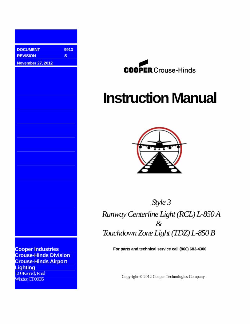
DOCUMENT 9913
REVISION S
November 27, 2012
Cooper Industries Crouse-Hinds Division Crouse-Hinds Airport Lighting 1200 Kennedy Road Windsor, CT 06095
Instruction Manual
Style 3
Runway Centerline Light (RCL) L-850 A &
Touchdown Zone Light (TDZ) L-850 B
For parts and technical service call (860) 683-4300
Copyright © 2012 Cooper Technologies Company
Document 9913 Rev. S Instruction Manual
Style 3 Runway Centerline Light L-850A & Touchdown Zone Light L-850B
ii
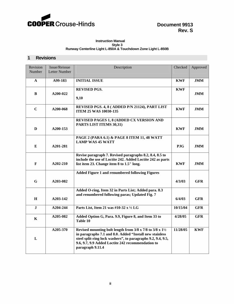
1 Revisions
Revision Number
Issue/Reissue Letter Number
Description Checked Approved
A A99-183 INITIAL ISSUE KWF JMM
B A200-022 REVISED PGS.
9,10
KWF
JMM
C A200-068 REVISED PGS. 4, 8 ( ADDED P/N 21124), PART LIST ITEM 25 WAS 10030-135
KWF JMM
D
A200-153
REVISED PAGES 1, 8 (ADDED CX VERSION AND PARTS LIST ITEMS 30,31)
KWF
JMM
E
A201-281
PAGE 2 (PARA 6.1) & PAGE 8 ITEM 11, 48 WATT LAMP WAS 45 WATT
PJG
JMM
F
A202-210
Revise paragraph 7. Revised paragraphs 8.2, 8.4, 8.5 to include the use of Loctite 242. Added Loctite 242 as parts list item 23. Change item 8 to 1.5" long.
KWF
JMM
G
A203-082
Added Figure 1 and renumbered following Figures
4/3/03
GFR
H
A203-142
Added O-ring, Item 32 in Parts List; Added para. 8.3 and renumbered following paras; Updated Fig. 7
6/4/03
GFR
J A204-244 Parts List, Item 21 was #10-32 x ½ LG 10/15/04 GFR
K A205-082 Added Option G, Para. 9.9, Figure 8, and Item 33 to
Table 10 4/28/05 GFR
L
A205-370 Revised mounting bolt length from 3/8 x 7/8 to 3/8 x 1½ in paragraphs 7.1 and 8.0. Added “Install new stainless steel split-ring lock washers”, to paragraphs 9.2, 9.4, 9.5, 9.6, 9.7, 9.9 Added Loctite 242 recommendation to paragraph 9.11.4
11/28/05 KWF
Document 9913 Rev. S Instruction Manual
Style 3 Runway Centerline Light L-850A & Touchdown Zone Light L-850B
iii
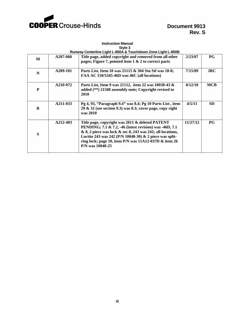
M A207-060 Title page, added copyright and removed from all other
pages; Figure 7, pointed item 1 & 2 to correct parts 2/23/07 PG
N A209-101 Parts List, Item 10 was 21115 & 304 Stn Stl was 18-8;
FAA AC 150/5345-46D was 46C (all locations) 7/15/09 JRC
P A210-072 Parts List, Item 9 was 21112, item 22 was 10038-43 &
added (**) 21508 assembly note; Copyright revised to 2010
8/12/10 MCB
R A211-033 Pg 4, 93, ”Paragraph 9.4” was 8.4; Pg 10 Parts List , item
29 & 32 (see section 9.3) was 8.3; cover page, copy right was 2010
4/5/11
SD
S
A212-403 Title page, copyright was 2011 & deleted PATENT PENDING; 7.1 & 7.2, -46 (latest revision) was -46D, 7.1 & 8, 2 piece was lock & sec 8, 243 was 242; all locations, Loctite 243 was 242 (P/N 10048-30) & 2 piece was split-ring lock; page 10, item P/N was 11A12-037D & item 26 P/N was 10048-25
11/27/12 PG
Document 9913 Rev. S Instruction Manual
Style 3 Runway Centerline Light L-850A & Touchdown Zone Light L-850B
iv
2 Limited Product Warranty
THE FOLLOWING WARRANTY IS EXCLUSIVE AND IN LIEU OF ALL OTHER WARRANTIES, WHETHER EXPRESS, IMPLIED OR STATUTORY, INCLUDING, BUT NOT BY WAY OF LIMITATION, ANY WARRANTY OF MERCHANTABILITY OR FITNESS FOR ANY PARTICULAR PURPOSE.
Crouse-Hinds Airport Lighting Products ( “the Company”) warrants to each original Buyer of Products manufactured by the Company that such Products are, at the time of delivery to the Buyer, free of material and workmanship defects, provided that no warranty is made with respect to:
(a) any Product which has been repaired or altered in such a way, in Company’s judgment, as to affect the Product adversely;
(b) any Product which has, in Company’s judgment, been subject to negligence, accident or improper storage;
(c) any Product which has not been operated and maintained in accordance with normal practice and in conformity with recommendations and published specification of Company; and,
(d) any Products, component parts or accessories manufactured by others but supplied by Company (any claims should be submitted directly to the manufacturer thereof).
Crouse-Hinds Airport Lighting Products’ obligation under this warranty is limited to use of reasonable means to repair or, at its option, replace, during normal business hours, at any authorized service facility of Company, any Products which in its judgment proved not to be as warranted within the applicable warranty period. All costs of transportation of Products claimed not to be as warranted and of repaired or replacement Products to or from such service facility shall be borne by Purchaser. Company may require the return of any Product claimed not to be as warranted to one of its facilities as designed by Company, transportation prepaid by Purchaser, to establish a claim under this warranty. The cost of labor for installing a repaired or replacement product shall be borne by Purchaser. Replacement parts provided under the terms of this warranty are warranted for the remainder of the warranty period of the Products upon which they are installed to the same extent as if such parts were original components thereof. Warranty services provided under the Agreement do not assure uninterrupted operations of Products; Company does not assume any liability for damages caused by any delays involving warranty service. The warranty period for the Products is 24 months from date of shipment or 12 months from date of first use whichever occurs first.
Document 9913 Rev. S Instruction Manual
Style 3 Runway Centerline Light L-850A & Touchdown Zone Light L-850B
v
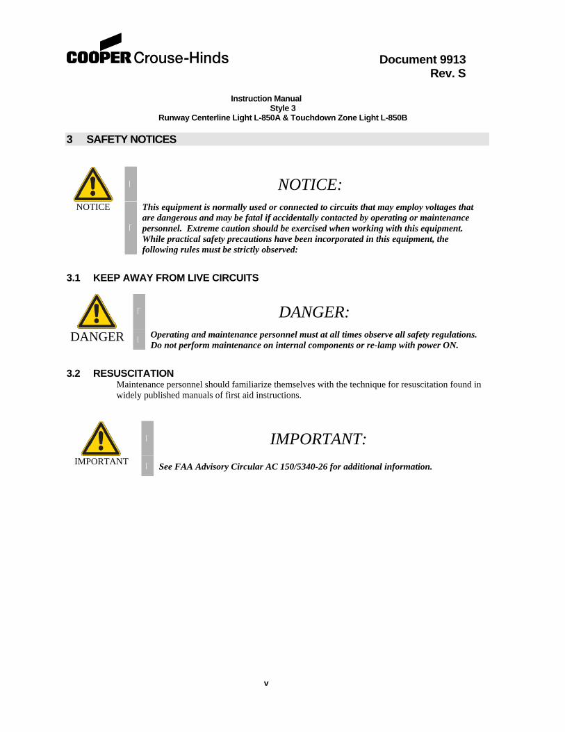
3 SAFETY NOTICES
NOTICE: NOTICE
This equipment is normally used or connected to circuits that may employ voltages that are dangerous and may be fatal if accidentally contacted by operating or maintenance personnel. Extreme caution should be exercised when working with this equipment. While practical safety precautions have been incorporated in this equipment, the following rules must be strictly observed:
3.1 KEEP AWAY FROM LIVE CIRCUITS
DANGER:
DANGER Operating and maintenance personnel must at all times observe all safety regulations. Do not perform maintenance on internal components or re-lamp with power ON.
3.2 RESUSCITATION Maintenance personnel should familiarize themselves with the technique for resuscitation found in widely published manuals of first aid instructions.
IMPORTANT: IMPORTANT
See FAA Advisory Circular AC 150/5340-26 for additional information.
Document 9913 Rev. S Instruction Manual
Style 3 Runway Centerline Light L-850A & Touchdown Zone Light L-850B
vi
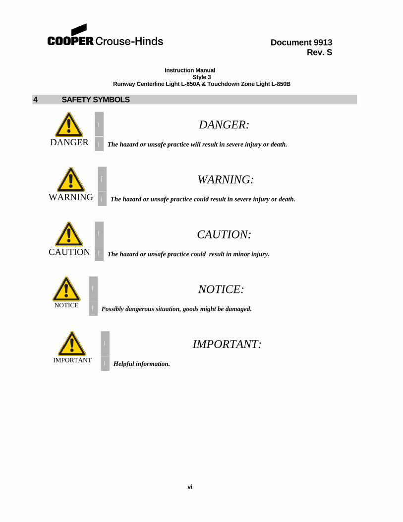
4 SAFETY SYMBOLS
DANGER:
DANGER The hazard or unsafe practice will result in severe injury or death.
WARNING:
WARNING The hazard or unsafe practice could result in severe injury or death.
CAUTION:
CAUTION The hazard or unsafe practice could result in minor injury.
NOTICE: NOTICE
Possibly dangerous situation, goods might be damaged.
IMPORTANT: IMPORTANT
Helpful information.
Document 9913 Rev. S Instruction Manual
Style 3 Runway Centerline Light L-850A & Touchdown Zone Light L-850B
vii
5 TABLE OF CONTENTS
Title Page…. ....................................................................................................................... i 1.0 Revisions ..................................................................................................................... ii 2.0 Limited Product Warranty. ............................................................................................ Iii 3.0 Safety Notices .............................................................................................................. iv 4.0 Safety Symbols …………………………………………….. ............................................ v 5.0 Table of Contents ........................................................................................................ vi 6.0 Part Number Explanation ............................................................................................. 1 7.0 General Description ...................................................................................................... 2
7.1 Runway Centerline Light, L-850A ......................................................................... 2 7.2 Touchdown Zone Light L-850B ............................................................................ 2
8.0 Installation ..................................................................................................................... 3 9.0 Maintenance ................................................................................................................. 3
9.1 Cleaning Lenses ................................................................................................... 3 9.2 Relamping ............................................................................................................ 4 9.3 Seal Revisions ...................................................................................................... 4 9.4 Gasket Replacement ........................................................................................... 5 9.5 O-Ring Replacement ............................................................................................ 5 9.6 Lens Replacement ............................................................................................... 6 9.7 Feed-thru Replacement ....................................................................................... 6 9.8 Pressure Test ....................................................................................................... 6 9.9 External Support Ring Gasket Replacement …… ............................................... 7 9.10 Cleanliness and Workmanship ............................................................................. 7 9.11 Maintenance Program .......................................................................................... 7
10.0 Parts List ……………………………………………………………………………….. 10 Figure 1 - Lamp Orientation ........................................................................................... 2
Figure 2 - 19999 Installation ( Lifting )Tool .................................................................... 9
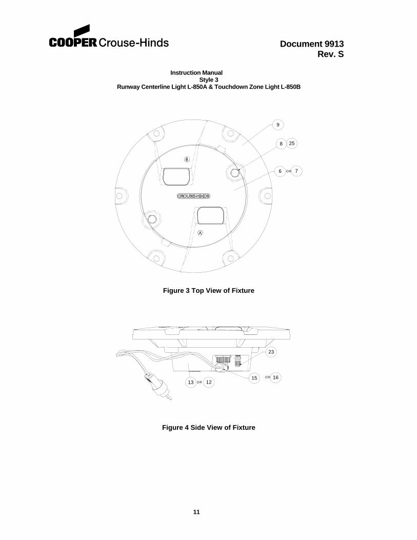
Figure 3 - Top View of Fixture ........................................................................................ 11
Figure 4 - Side View of Fixture ........................................................................................ 11
Figure 5 - Feed-thru adapter detail ................................................................................. 12
Figure 6 - Bottom View of Fixture ................................................................................... 12
Figure 7 - Cut-away View of Fixture ................................................................................. 13
Figure 8 - Side View of Fixture with Optional External Support Ring Gasket ….. ........... 14
Document 9913 Rev. S Instruction Manual
Style 3 Runway Centerline Light L-850A & Touchdown Zone Light L-850B
1
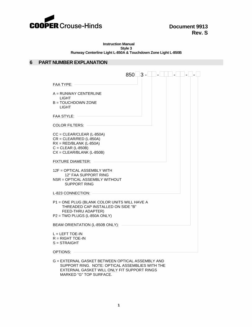
6 PART NUMBER EXPLANATION
FAA TYPE:
A = RUNWAY CENTERLINELIGHT
B = TOUCHDOWN ZONELIGHT
FAA STYLE:
COLOR FILTERS:
CC = CLEAR/CLEAR (L-850A)CR = CLEAR/RED (L-850A)RX = RED/BLANK (L-850A)C = CLEAR (L-850B)CX = CLEAR/BLANK (L-850B)
FIXTURE DIAMETER:
12F = OPTICAL ASSEMBLY WITH12" FAA SUPPORT RING
NSR = OPTICAL ASSEMBLY WITHOUTSUPPORT RING
L-823 CONNECTION:
P1 = ONE PLUG (BLANK COLOR UNITS WILL HAVE ATHREADED CAP INSTALLED ON SIDE "B"FEED-THRU ADAPTER)
P2 = TWO PLUGS (L-850A ONLY)
BEAM ORIENTATION (L-850B ONLY):
L = LEFT TOE-INR = RIGHT TOE-INS = STRAIGHT
OPTIONS:
G = EXTERNAL GASKET BETWEEN OPTICAL ASSEMBLY ANDSUPPORT RING. NOTE: OPTICAL ASSEMBLIES WITH THEEXTERNAL GASKET WILL ONLY FIT SUPPORT RINGSMARKED "G" TOP SURFACE.
850 3 - - - - -
Document 9913 Rev. S Instruction Manual
Style 3 Runway Centerline Light L-850A & Touchdown Zone Light L-850B
2
7 General Description
7.1 Runway Centerline Light, L-850A The Crouse-Hinds Style 3 Runway Centerline Light is an ITS verified FAA L-850A per FAA AC 150/5345-46 (latest revision). It is designed for installation at the centerline of runways or any other location where visual guidance of moving aircraft or ground vehicles is desirable. The fixture is designed to fit on a FAA L-868, steel, Size B light base per FAA AC 150/5345-42(latest version), and have a total height above grade/ground level of .250 inch. The fixture is bi-directional, projecting two beams of light 180° apart. It is weatherproof and will endure roll over loads without damage. The light fixture consists of a ductile iron support ring and a removable aluminum optical assembly. The ductile iron ring is mounted to a light base with six bolts (3/8-16 UNC x1½ lg., stn. stl.) and 2 piece washers (3/8, stn. Stl.). The aluminum optical housing is secured to the ductile iron ring using two high-strength bolts and two high-strength shear pins. The optical housing has a die cast inner cover that is attached using 4 screws. A polyurethane o-ring is used to provide a watertight seal between the inner cover and the optical housing (see section 9.3). An optional silicone gasket is bonded to the outside of the inner cover to provide a watertight seal between the optical assembly and the ductile iron support ring. Two 48-watt, MR-16 lamps are secured to two brackets, which are fastened to the bottom housing. Electrical connections are made at either one or two feed-thru assemblies in the inner cover. The feed-thrus have ITS verified L-823 plugs for connecting to FAA L-830/ L-831 Isolation Transformers. Lenses are held into the aluminum housing with a bracket, gasket, molded elastomeric boot and two screws. Red dichroic-coated lenses are available from the factory, or may be installed in the field. All hardware is type 18-8 stainless steel. The complete light unit is 11.94 inches in diameter, 3.63 inches deep, and weighs 20 lbs.
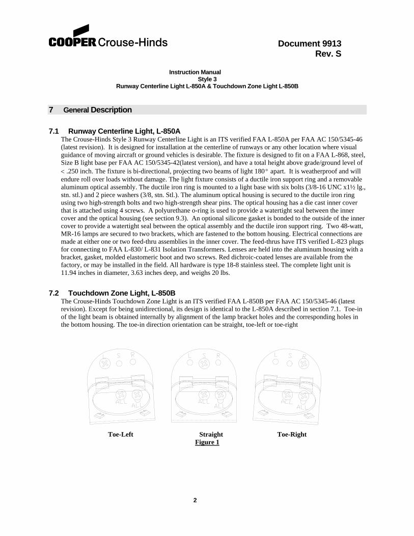
7.2 Touchdown Zone Light, L-850B The Crouse-Hinds Touchdown Zone Light is an ITS verified FAA L-850B per FAA AC 150/5345-46 (latest revision). Except for being unidirectional, its design is identical to the L-850A described in section 7.1. Toe-in of the light beam is obtained internally by alignment of the lamp bracket holes and the corresponding holes in the bottom housing. The toe-in direction orientation can be straight, toe-left or toe-right
Toe-Left Straight Toe-Right
Figure 1
Document 9913 Rev. S Instruction Manual
Style 3 Runway Centerline Light L-850A & Touchdown Zone Light L-850B
3
CAUTION:
CAUTION Never handle the light assembly by the leads as this can break the waterproof seal.
8 Installation
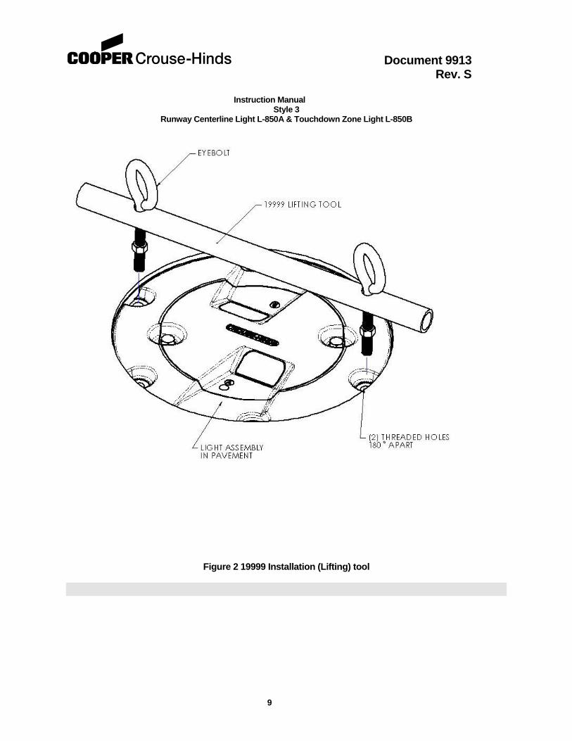
The Style 3 RCL and TDZ light units are shipped complete, including the lamp(s), and are ready for installation as received. Installation of the light unit is to be done with primary POWER OFF and SECURED. At each light location, install a steel, Size B, 12 inch deep minimum, L-868 Light Base per FAA AC 150/5340-4 (latest revision). Install the light base with two opposite bolt holes perpendicular to the runway centerline. Place the properly sized isolation transformer(s) in the light base and make necessary primary power connections using L-823 connectors. The RCL light unit requires either two 45 watt, 6.6A secondary transformers for the two lead version, or one 100 watt, 6.6A secondary transformer for the single lead version. The TDZ light unit requires one 45 watt, 6.6A secondary transformer. Verify that the mounting flange on the light base is clean and the o-ring (optional on deep cans) is coated with Dow Corning FS 1292 grease and is in place on the light base. Connect the plug(s) from the light unit to the secondary(ies) of the previously installed isolation transformer(s). Installation tool, Crouse-Hinds P/N 19999, will ease in the installation and removal of the light unit (See Figure 2). The threaded eyebolts on the lifting tool screw into threaded holes in the light fixture. Lower the light unit straight down onto the base. The light fixture is subject to optical misalignment or mechanical damage if not seated properly. Verify the light beam(s)/color(s) are properly orientated for the individual location. Secure the light fixture to the base with six 3/8-16 UNC x 1½ lg. stn. Stl. bolts and 2 piecewashers and tighten to 225 -0 +10 in-lbs. (19-20 ft-lbs.). It is recommended that Loctite 243 be used on the mounting bolts to prevent loosening due to vibration. It is highly recommended for fixtures subjected to repeated aircraft impacts and roll-overs.
9 Maintenance
The preferred method of maintaining these lights is to periodically and systematically replace the Optical Assembly and return it to the maintenance shop for renovation. As an alternative, the Optical Assembly can be serviced in the field. However, it is recommended that field servicing be limited to cleaning the lens as described in section 9.1 and to lamp replacements as described in section 9.2.
9.1 Cleaning Lenses With a compressed air blast or suitable brushes, remove all accumulated debris from the light channel. Clean the outer surface of the prism with a detergent solution. If the lens is coated with a substance impervious to the detergent, a suitable solvent should be sparingly applied with a wad of cotton or a patch of cloth on the end of a wood splint. After the solvent has acted the remaining solvent and softened coating should be removed with a clean piece of cotton or cloth. Care should be taken to avoid excessive contact between the solvent and the lens seal. Remove all remaining solvent from lens and seal. A gentle air blast may be used.
Document 9913 Rev. S Instruction Manual
Style 3 Runway Centerline Light L-850A & Touchdown Zone Light L-850B
4
9.2 Relamping
WARNING:
WARNING Light assembly parts are hot when lamp is energized and remain hot for a short time after lamp/fixture is turned off.
Remove and secure power to the fixture. Separate the Optical Assembly from the outer ring by removing the two bolts. There are two pry slots in the optical housing to help separate the Optical Assembly from the support ring. Turn the Optical Assembly upside down and remove the four screws holding the inner cover to the light housing. Disconnect the lamp leads from the feed-thru terminals. Remove the Lamp Assembly by gently pulling up on the lamp reflector base. Inspect the feed-thru terminal for signs of corrosion. Replace feed-thru assemblies per paragraph 9.7. Clean the inside surfaces of the lens(es) with denatured alcohol. Inspect the lamp holder bracket(s) for loose hardware; tighten the mounting screws to 30 in-lbs.
CAUTION:
CAUTION
Touching the quartz bulb with bare fingers may seriously shorten lamp life. If the bulb has been touched, wipe it clean with a piece of lens cleaning tissue or similar material moistened with denatured alcohol.
Install the new lamp by reversing the procedure above. Make certain the rim of the reflector is flush against the bracket and seated against the two pins at the bottom of the bracket. Connect the lamp leads to the feed-thru terminals. Inspect/ replace the inner cover o-ring per paragraph 9.5 (see section 9.3). Assemble the inner cover onto the light housing. The screw hole patterns in the inner cover and light housing are offset to insure proper alignment. Tighten the mounting screws to 30 in-lbs. Clean the mounting flange area of the support ring. Place the Optical Assembly into the support ring. Install new stainless steel 2 piece washers. Apply Loctite 243 per manufacturer’s instructions, to both mounting bolts and immediately torque them to 225 -0+10 in-lbs.
9.3 Seal Revision Fixtures manufactured prior to May 2003 use a high temperature silicone gasket (P/N 21124), bonded to the inner cover (P/N 21118-X), to provide a watertight seal between the inner cover and the optical housing (P/N 21105-X). Paragraph 9.4, Gasket Replacement, details the instructions on how to replace the 21124 gasket. Starting in May 2003, a polyurethane o-ring (P/N 10035-62) was used to provide the watertight seal between the optical housing and inner cover. The o-ring is not bonded to either the optical housing or inner cover. This revision requires an o-ring groove to be machined into the 21105-X optical housing, and all replacement optical housings will be supplied with the o-ring groove. Paragraph 9.5, O-Ring Replacement, details the instructions on how to replace the 10035-62 o-ring. To retrofit an older style inner cover to the o-ring groove style optical housing, cut the 21124 gasket flush with the mounting surface on the inner cover with a razor blade.
Document 9913 Rev. S Instruction Manual
Style 3 Runway Centerline Light L-850A & Touchdown Zone Light L-850B
5
9.4 Gasket Replacement Everytime the Optical Assembly is opened the gasket must be closely examined and replaced if necessary. Any gasket that is stretched, torn, has a permanent set or some other defect, which would prevent it from forming a watertight seal must be replaced with a new gasket. Remove the old gasket from the groove in the inner cover. Carefully clean the flange mating surfaces and the inner cover groove. This can be done by carefully scraping. Take care not to damage the mating surface and the bottom and sides of the groove. Coat the gasket (P/N 21124) with a thin layer of Dow Corning FS 1292 Lubricating grease. Position the new gasket in the center of the groove and press it into place. The grease will hold the gasket in place while the inner cover is positioned on the light housing. Torque the inner cover screws to 30 in-lbs. Perform a pressure test as described in paragraph 9.8. Clean the mounting flange area of the support ring. Place the Optical Assembly into the support ring. Install new stainless steel 2 piece washers. Apply Loctite 243 per manufacturer’s instructions, to both mounting bolts and immediately torque them to 225 -0+10 in-lbs.
9.5 O-Ring Replacement Every time the Optical Assembly is opened the o-ring must be closely examined and replaced if necessary. Any o-ring that is stretched, torn, has a permanent set or some other defect, which would prevent it from forming a watertight seal must be replaced with a new o-ring. Remove the old o-ring from the groove in the optical housing. Carefully clean the o-ring groove and flange mating surface on the inner cover. Take care not to damage the mating surface or o-ring groove. Coat the o-ring (P/N 10035-62) with a thin layer of Dow Corning FS 1292 Lubricating grease. Position the new o-ring in the groove and press it into place. Torque the inner cover screws to 30 in-lbs. Perform a pressure test as described in paragraph 9.8. Clean the mounting flange area of the support ring. Place the Optical Assembly into the support ring. Install new stainless steel 2 piece washers. Apply Loctite 243 per manufacturer’s instructions, to both mounting bolts and immediately torque them to 225 -0+10 in-lbs.
IMPORTANT IMPORTANT
NOTE – A bad gasket seal is the most common cause of inset fixture leaks. It is strongly recommended that a new gasket be installed every time the Optical Assembly is opened. NOTE – The groove is designed to be wider than the gasket. This provides room for displacement of the gasket when compressed between the housing and mating surface. Properly tightened screws are important in obtaining a complete seal.
Document 9913 Rev. S Instruction Manual
Style 3 Runway Centerline Light L-850A & Touchdown Zone Light L-850B
6
9.6 Lens Replacement If a lens is broken, leaks or is badly pitted or scarred, it must be replaced. It is highly recommended that this task be performed in a clean shop environment. Use Lens Replacement Kit P/N 21126-C for clear lenses, and kit P/N 21126-R for red lenses. Remove and secure power to the fixture. Separate the Optical Assembly from the outer ring by removing the two bolts. There are two pry slots in the optical housing to help separate the Optical Assembly from the support ring. Turn the Optical Assembly upside down and remove the four screws holding the inner cover to the light housing. Remove the two lens retaining bracket screws from the light housing. Remove the lens-retaining bracket and discard the lens-retaining gasket. Firmly push the lens/boot assembly from the outside of the light housing; discard the old lens and boot. Thoroughly clean the lens opening with denatured alcohol and allow to dry. Inspect the lens opening for scratches or pits, a damaged lens opening surface will not seal properly. Place a new lens boot (P/N 21103) over the replacement lens (P/N 21102-C or 21102-R). Apply a thin coat of Dow Corning FS 1292 grease over the entire outside surface of the lens boot. Align the lens/boot assembly in the lens opening and press it into place. Verify that the lens boot is not pinched in the lens opening. Using a new lens retaining gasket (P/N 21101), fasten the lens retaining bracket (P/N 21100) to the light housing. Torque the mounting screws to 30 in-lbs. Assembly the inner cover onto the light housing. The screw hole patterns in the inner cover and light housing are offset to insure proper alignment. Torque the mounting screws to 30 in-lbs. Perform a pressure test per paragraph 9.8. Clean the mounting flange area of the support ring. Place the Optical Assembly into the support ring. Install new stainless 2 piece washers. Apply Loctite 243 per manufacturer’s instructions, to both mounting bolts and immediately torque them to 225 -0+10 in-lbs.
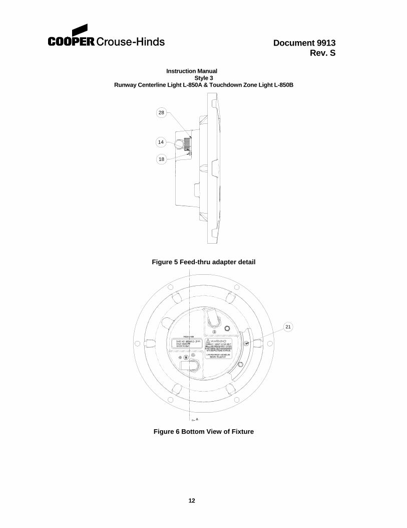
9.7 Feed-thru Replacement Remove and secure power to the fixture. Separate the Optical Assembly from the outer ring by removing the two bolts. There are two pry slots in the optical housing to help separate the Optical Assembly from the support ring. Turn the Optical Assembly upside down and remove the four screws holding the inner cover to the light housing. Disconnect the lamp leads from the feed-thru terminals. Remove the feed-thru by unscrewing the retaining collar. Clean the mounting surface with Isopropyl Alcohol and allow to dry. Apply a thin coat of Dow Corning FS 1292 grease to the mounting flange of a new feed-thru (P/N 21121 for 2 lamp/ 1 plug, or P/N 21122 for 1 lamp/ 1 plug). Apply a drop of Loctite 242 to the feed-thru adapter threads. Screw the feed-thru retaining collar onto the adapter; refer to Figure 6 for proper inner cover/ feed-thru orientation. Torque the retaining collar to 30 in-lbs. Assembly the inner cover onto the light housing. The screw hole patterns in the inner cover and light housing are offset to insure proper alignment. Torque the mounting screws to 30 in-lbs. . Perform a pressure test per paragraph 9.8. Clean the mounting flange area of the support ring. Place the Optical Assembly into the support ring. Install new stainless steel 2 piece washers. Apply Loctite 243 per manufacturer’s instructions, to both mounting bolts and immediately torque them to 225 -0+10 in-lbs.
9.8 Pressure Test A light fixture should be subjected to a 20-psi air pressure test to verify that it is waterproof whenever it has been opened or components have been replaced. A tire valve style pressure fitting is located on the bottom of the inner cover. Pressurize the fixture to 20-psi then place it in a tub of water or use a soap solution to locate escaping air bubbles. Carefully inspect the areas around the lens, inner cover seal, and feed-thru adapter for leaks. Relieve the internal air pressure before installing the fixture or attempting to repair a leak.
Document 9913 Rev. S Instruction Manual
Style 3 Runway Centerline Light L-850A & Touchdown Zone Light L-850B
7
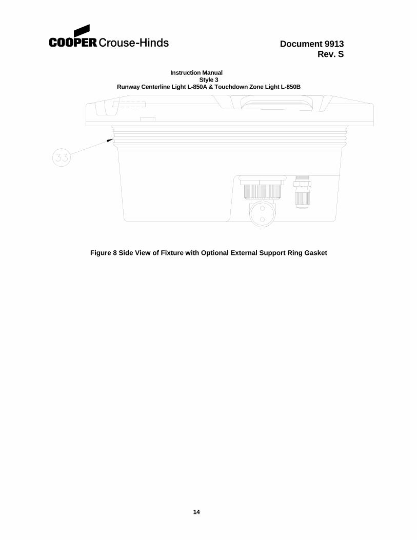
9.9 External Support Ring Gasket Replacement Everytime a light fixture with the optional external support ring gasket is removed from the support ring, the gasket on the inner cover should be examined and replaced if necessary. Any gasket that is stretched, torn, has a permanent set or some other defect, will allow water to enter the light base. Remove the old gasket from the inner cover by carefully scraping. Take care not to damage the inner cover. Form a thin bead of high temperature silicone adhesive, such as GE RTV 106, on the inner cover sealing surface. Position the new gasket (P/N 21180) on the inner cover in the same location as the old gasket. Allow the silicone to cure for 4 to 12 hours. Cure times depend on the amount of silicone use, ambient temperature, and relative humidity. Apply a thin coat of Dow Corning FS 1292 grease over the entire outside surface of the gasket before placing in the support ring. Install new stainless steel 2 piece washers. Apply Loctite 243 per manufacturer’s instructions, to both mounting bolts and immediately torque them to 225 -0+10 in-lbs.
WARNING:
WARNING
Do not exceed 20 psi when pressure testing the fixture. Serious injury and/or permanent damage to the fixture may result if a higher air pressure is used. Once the pressure test is complete be sure to relieve the air pressure.
9.10 Cleanliness and Workmanship
Service life depends upon the entire assembly being waterproof. All surfaces must be clean, dry and free of all foreign matter if the light fixture is to operate for extended periods without requiring maintenance.
9.11 Maintenance Program In order to insure maximum light fixture life, the installed units should be subject to a maintenance program in accordance with the following:
A daily operation check should be made of the lighting fixture. The lights should be energized and visually inspected. If any lamps are out, the location of the fixture should be recorded and the lamps replaced at a time when the circuit is de-energized. (See Section 9.2 )
Document 9913 Rev. S Instruction Manual
Style 3 Runway Centerline Light L-850A & Touchdown Zone Light L-850B
8
9.11.1 Regular cleaning is necessary in order to insure that inset lighting fixtures operate at maximum efficiency. The lens and channel in front of the lens should be cleaned periodically with a soft cloth and solvent. The weather and the location of the fixtures will dictate the regularity and type of cleaning.
9.11.2 Snowplow operators should exercise extra care not to strike the light fixtures with snowplow blades. After snowplow removal operations, inspect all light fixtures to locate and replace if necessary, any damaged Light Assemblies. Passes over the light rows should be made with a power broom only if practical. Whenever snowplows must traverse in-pavement light fixtures, they should be traveling at less than 5 mph or have the blades lifted clear of the fixtures. Recommended snow removal techniques are described in AC 150/5200-23.
9.11.3 The light is designed to exclude both ground and surface water from entering. If the lights are not properly maintained (i.e., bolts tightened and seals in good condition) water may enter the fixture. To prevent this from occurring, it is recommended that each fixture be inspected for the presence of water at least once a month. More frequent inspection is desirable during and following rainy seasons.
9.11.4 Optical Assembly and support ring hold-down bolts should be checked for proper torque (225 +5, -0 in-lbs.) at least once every three months or whenever a fixture is serviced regardless of the season. Light fixtures in and around the Touchdown Zone area are especially prone to vibration damage if the mounting bolts are not properly torqued. It is recommended that Loctite 243 be used on the mounting bolts to prevent loosening due to vibration. The mounting surfaces of the light base and support ring must be clean and free of foreign matter when checking mounting bolts.
9.11.5 If any fixture contains water, the water should be removed and the entire fixture cleaned and dried. Perform a pressure test per paragraph 9.8 to locate the source of the leak. Replace the bottom cover gasket or o-ring; see Section 9.3, 9.4 and 9.5.
Document 9913 Rev. S Instruction Manual
Style 3 Runway Centerline Light L-850A & Touchdown Zone Light L-850B
9
Figure 2 19999 Installation (Lifting) tool
Document 9913 Rev. S Instruction Manual
Style 3 Runway Centerline Light L-850A & Touchdown Zone Light L-850B
10
10 Parts List
ITEM PART
NUMBER
850A3-CC-12F-
P1
QTY
850A3-CR-12F-
P1
QTY
850A3-CC-12F-
P2
QTY
850A3-CR-12F-
P2
QTY
850B3-C-12F-P1- L, -R, -S
QTY
850B3-CX -12F- P1- L, -R, -S
QTY
DESCRIPTION
1 21100 2 2 2 2 1 2 BRACKET, LENS RETAINING, 18-8 STN STL.
2 21101 * 2 2 2 2 1 1 GASKET, LENS RETAINING
3 21102-C * 2 1 2 1 1 2 LENS, CLEAR
4 21102-R * 0 1 0 1 0 0 LENS, COLOR COATED RED
5 21103 * 2 2 2 2 1 2 BOOT, LENS
6 21105-1 0 0 0 0 1 0 OPTICAL HOUSING, MACHINED, TDZ, ALUM.
7 21105-2 1 1 1 1 0 1 OPTICAL HOUSING, MACHINED, RCL, ALUM.
8 10C10-037D40 2 2 2 2 2 2 BOLT, 3/8-16 X 1.5 LG., 18-8 STN STL.
9 ** 1 1 1 1 1 1 SUPPORT RING, MACHINED/PLATED, DUCTILE IRON
10 21461 2 2 2 2 1 1 LAMP BRACKET ASSEMBLY, 304 STN STL.
11 21116 2 2 2 2 1 1 LAMP/REFLECTOR ASSEMBLY, 48 W, 6.6 A.
12 21118-1 0 0 0 0 1 0 BOTTOM COVER, MACHINED, TDZ, ALUM.
13 21118-2 1 1 1 1 0 1 BOTTOM COVER, MACHINED, RCL, ALUM.
14 21120 2 2 2 2 1 2 ADAPTER, THREADED, FEED-THRU, ALUM.
15 21121 1 1 0 0 0 0 FEED-THRU ASSEMBLY, 2 LAMP/1 PLUG, ALUM.
16 21122 0 0 2 2 1 1 FEED-THRU ASSEMBLY, 1 LAMP/1 PLUG, ALUM.
17 21123 0 0 1 1 0 0 BAFFLE, RCL
18 10000-471 1 1 1 1 1 1 SCREW, SEMS, PAN HD TYPE 1A CROSS, GREEN, #10-32 X 3/8 LG, 18-8 STN STL.
19 10000-468 4 4 4 4 2 4 SCREW, SEMS, PAN HD TYPE 1A CROSS/DRI-LOC, #10-32 X 1/2 LG, 18-8 STN STL.
20 10000-469 6 6 8 8 3 3 SCREW, SEMS, PAN HD TYPE 1A CROSS/DRI-LOC, #8-32 X 3/8 LG, 18-8 STN STL.
21 10000-470 4 4 4 4 4 4 SCREW, 100 FLAT HD/DRI-LOC, #10-32 X 7/16 LG, 18-8 STN STL.
22 ** 2 2 2 2 2 2 DOWEL PIN, 3/8 X 3/4 LG,
23 10048-30 A/R A/R A/R A/R A/R A/R MEDIUM STRENGTH THREADLOCKER, LOCTITE 242
24 10037-795 1 1 1 1 1 1 FITTING, PRESSURE TEST, 1/8-NPT
25 10030-149 2 2 2 2 2 2 WASHER, 2 PIECE, 3/8, 18-8 STN STL.
26 10048-140 * A/R A/R A/R A/R A/R A/R SILICONE GREASE
27 10048-106 A/R A/R A/R A/R A/R A/R PIPE SEALANT PASTE
28 10035-0061 2 2 2 2 1 2 O-RING, FEED-THRU ADAPTER
29 21124 1 1 1 1 1 1 GASKET, BOTTOM COVER (SEE SECTION 9.3)
30 21143 0 0 0 0 0 1 GASKET, BLANK COLOR, LENS RETAINING
31 10037-805 0 0 0 0 0 1 CAP, 7/8-16 UN-2B THREAD
32 10035-62 1 1 1 1 1 1 O-RING, 3/32, (SEE SECTION 9.3)
33 21180 A/R A/R A/R A/R A/R A/R EXTERNAL SUPPORT RING GASKET (OPTIONAL)
* These parts are included in a Lens Replacement Kit. Use kit P/N 21126-C for clear lenses, and kit P/N 21126-R for red lenses. Each kit contains parts to replace one lens. ** These parts come assembled as P/N 21508.
Document 9913 Rev. S Instruction Manual
Style 3 Runway Centerline Light L-850A & Touchdown Zone Light L-850B
11
9
6
8
7OR
25
Figure 3 Top View of Fixture
16
23
1513
OR
12OR
Figure 4 Side View of Fixture
Document 9913 Rev. S Instruction Manual
Style 3 Runway Centerline Light L-850A & Touchdown Zone Light L-850B
12
14
28
18
Figure 5 Feed-thru adapter detail
A
21
Figure 6 Bottom View of Fixture
Document 9913 Rev. S Instruction Manual
Style 3 Runway Centerline Light L-850A & Touchdown Zone Light L-850B
13
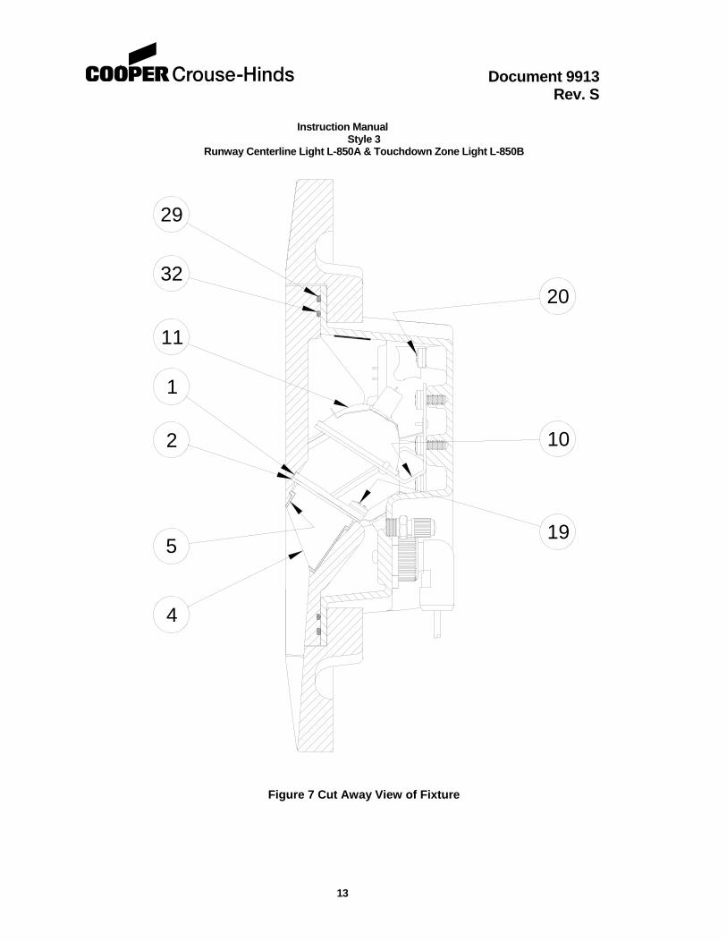
32
29
11
1
5
4
19
10
20
2
Figure 7 Cut Away View of Fixture
Document 9913 Rev. S Instruction Manual
Style 3 Runway Centerline Light L-850A & Touchdown Zone Light L-850B
14
Figure 8 Side View of Fixture with Optional External Support Ring Gasket