Embed Size (px)
Citation preview
The Israel Electric Corporation LTD
Engineering Project Group
Engineering Division
Electrical Sector
This document contains proprietary information of Israel Electric Corporation (IEC) and is to be used for the Project and for the sole purpose for which it is furnished. The
recipient or anyone on its behalf shall not be entitled to use the document, or any part thereof, for any other purpose without the prior written approval of IEC. The
recipient shall keep this document in strict confidence and shall not transfer, disclose or divulge it to any other person without the prior written approval of IEC.
IEC is the sole owner of all intellectual property rights associated with this document and any future work product thereof.
Of:
28
Page:
1
LOW VOLTAGE SWITCHGEAR AND
CONTROLGEAR ASSEMBLIES OF
FIXED-MOUNTED DESIGN
STANDARD No.
EPD-A.05
DOCUMENT: Electrical Standard Specification.
SUBJECT: LOW VOLTAGE SWITCHGEAR AND
CONTROLGEAR ASSEMBLIES OF
FIXED-MOUNTED DESIGN
Cancels: EPD-5/02 Rev. F Rev.
�
Applicable:
11/2009
Date:
10/2009
The Israel Electric Corporation LTD
Engineering Project Group
Engineering Division
Electrical Sector
This document contains proprietary information of Israel Electric Corporation (IEC) and is to be used for the Project and for the sole purpose for which it is furnished. The
recipient or anyone on its behalf shall not be entitled to use the document, or any part thereof, for any other purpose without the prior written approval of IEC. The
recipient shall keep this document in strict confidence and shall not transfer, disclose or divulge it to any other person without the prior written approval of IEC.
IEC is the sole owner of all intellectual property rights associated with this document and any future work product thereof.
:פרויקט
Electrical Standard Specification for :נושא
Low voltage switchgear and controlgear assemblies
of fixed-mounted design : סוג מסמ�
עקרו� תכנו� �
תזכיר תכנוני �
מפרט�
נייר עמדה �
חישובי��
בשימת מחשר �
נוהל/ תק� �
02 01 � 'הוצאה מס
10/2009 :תארי�
חתימה ש� חתימה ש� חתימה ש� ארשבסקי. ו הכי�
/הראל. ס בדק ושלר. ר
זיידמ�. מ תוא�
פינ�. א תוא�
סנטו. ג תוא�
תוא�
רוזנברג. א אישר
ה'אלצ. ר ל"ד אישרר
:ה"הפצה אל ה
ש� לידיעת
ש� לידיעת
ש� לידיעת
ש� לידיעת
X מאירי. ב X ברגר. ל X שטיינברג. ג X ה'אלצ. ל
X אופק. ש X קאופמ�. ז X רג!. ג X רוזנברג. א
X תיק X סיליקי. י X אליעזר. ד X פינ�. א
X שרושי. י X וורטמ�. ל X זיידמ�. מ
X רובינשטיי�. א X קליי�. ר X ושלר. ר
X סוסקי�. י X זוניס. ב X פינרו. א
X לזר. א X זאק. מ X פלינר. ל
X אלכסנדרוב. א X דוידוב. מ X הראל. ס
X לעיאלק. מ X גראוס. ג X דימיטריו. א
X סנטו. ג X ציטרינל. ב X פישמ�. א
מ"חברת החשמל לישראל בע חטיבת פרויקטי� הנדסיי�
אג� תכנו� הנדסי המגזר החשמלי
:מספר המסמ
:מספר הנוהל
EPD-A.05 The Israel Electric Corporation Ltd.
Engineering Projects Group
Engineering Division
Electrical Sector
:הוצאה�
:ד!2
:מתו 28

The Israel Electric Corporation LTD
Engineering Project Group
Engineering Division
Electrical Sector
This document contains proprietary information of Israel Electric Corporation (IEC) and is to be used for the Project and for the sole purpose for which it is furnished. The
recipient or anyone on its behalf shall not be entitled to use the document, or any part thereof, for any other purpose without the prior written approval of IEC. The
recipient shall keep this document in strict confidence and shall not transfer, disclose or divulge it to any other person without the prior written approval of IEC.
IEC is the sole owner of all intellectual property rights associated with this document and any future work product thereof.
Of:
28
Page:
3
LOW VOLTAGE SWITCHGEAR
AND CONTROLGEAR ASSEMBLIES
OF FIXED-MOUNTED DESIGN
STANDARD No.
EPD-A.05
Content: Page
1. Scope 5
2. Definitions 5
3. Applicable Standards 6
4. General Requirements 6
5. Service Conditions 7
6. Structures and Housings 8
7. Switch����Disconnectors 10
8. Combination Starters 10
9. Circuit Breakers 11
10. Magnetic Starters 12
11. Control Transformers 13
12. Miniature Circuit Breakers 14
13. Control Devices 14
14. Space Heaters 15
15. Cooling Fans 15
16. Other Devices 16
17. Bus Bars 16
18. Grounding 17
19. Terminal Blocks and Wiring 17
20. Nameplates 17
21. Painting 17
22. Inspection and Tests
18
23. Quality Assurance
20
24. Package and Shipping 20
Cancels: EPD-5/02 Rev. F Rev.
-
Applicable:
11/2009
Date:
10/2009

The Israel Electric Corporation LTD
Engineering Project Group
Engineering Division
Electrical Sector
This document contains proprietary information of Israel Electric Corporation (IEC) and is to be used for the Project and for the sole purpose for which it is furnished. The
recipient or anyone on its behalf shall not be entitled to use the document, or any part thereof, for any other purpose without the prior written approval of IEC. The
recipient shall keep this document in strict confidence and shall not transfer, disclose or divulge it to any other person without the prior written approval of IEC.
IEC is the sole owner of all intellectual property rights associated with this document and any future work product thereof.
Of:
28
Page:
4
LOW VOLTAGE SWITCHGEAR
AND CONTROLGEAR ASSEMBLIES
OF FIXED-MOUNTED DESIGN
STANDARD No.
EPD-A.05
Content: Page
25. Technical Data and Documentation 21
26. List Of Standards 23
27. Annexures:
Annexure 1 – "Arrangement and colors
of pushbuttons, control
switches and indicating
lights"
24
Annexure 2 – Data to be specified in
Project Specification
(By Purchaser)
25
Annexure 3 – "Low voltage switchgear
and controlgear assembly
Data sheet"
26
Annexure 4 – "Low voltage switchgear
and controlgear assembly
Summary of data"
27
Cancels: EPD-5/02 Rev. F Rev.
-
Applicable:
11/2009
Date:
10/2009

The Israel Electric Corporation LTD
Engineering Project Group
Engineering Division
Electrical Sector
This document contains proprietary information of Israel Electric Corporation (IEC) and is to be used for the Project and for the sole purpose for which it is furnished. The
recipient or anyone on its behalf shall not be entitled to use the document, or any part thereof, for any other purpose without the prior written approval of IEC. The
recipient shall keep this document in strict confidence and shall not transfer, disclose or divulge it to any other person without the prior written approval of IEC.
IEC is the sole owner of all intellectual property rights associated with this document and any future work product thereof.
Of:
28
Page:
5
LOW VOLTAGE SWITCHGEAR
AND CONTROLGEAR ASSEMBLIES
OF FIXED-MOUNTED DESIGN
STANDARD No.
EPD-A.05
1. SCOPE
1.1. This Standard Specification applies for the design, manufacture and test of
the Low voltage switchgear and controlgear assemblies of fixed-mounted
design
1.2. All Low voltage switchgear and controlgear assemblies of fixed-mounted
design shall comply with this Standard Specification except where overruled
by specific requirements of the Project Specification.
1.3. This Standard Specification is not applicable for the Low voltage switchgear
assemblies of withdrawable unit design. This subject is covered by Standard
EPD-A.07.
1.4. For the Low voltage switchgear and controlgear assemblies, located in
hazardous areas, the relevant specific requirements shall be included in the
Project Specification. These supplementary requirements are covered by IEC
standards 60079 series and 61241 series.
2. DEFINITIONS
2.1. A Low voltage switchgear assembly is an assembly including a combination
of one or more switching devices (contactors, circuit breakers etc.) with
associated control, measuring, signaling, protective, regulating equipment,
etc., completely assembled with all the internal electrical and mechanical
interconnections and structural parts, intended for use in connection with
generation, transmission, distribution and conversion of electric energy.
This term covers an area of dedicated Plant power distribution cabinets,
different AC distribution cabinets, different DC distribution cabinets,
Lighting cabinets, etc.
2.2. A Low voltage controlgear assembly is an assembly, intended for the control
of electric energy consuming equipment, and including a combination of one
or more switching devices with associated control, measuring, signaling,
protective, regulating electromechanical and/or electronic equipment, etc.,
completely assembled with all the associated interconnections and structural
parts. This term covers an area of dedicated Plant control cabinets.
Cancels: EPD-5/02 Rev. F Rev.
-
Applicable:
11/2009
Date:
10/2009
The Israel Electric Corporation LTD
Engineering Project Group
Engineering Division
Electrical Sector
This document contains proprietary information of Israel Electric Corporation (IEC) and is to be used for the Project and for the sole purpose for which it is furnished. The
recipient or anyone on its behalf shall not be entitled to use the document, or any part thereof, for any other purpose without the prior written approval of IEC. The
recipient shall keep this document in strict confidence and shall not transfer, disclose or divulge it to any other person without the prior written approval of IEC.
IEC is the sole owner of all intellectual property rights associated with this document and any future work product thereof.
Of:
28
Page:
6
LOW VOLTAGE SWITCHGEAR
AND CONTROLGEAR ASSEMBLIES
OF FIXED-MOUNTED DESIGN
STANDARD No.
EPD-A.05
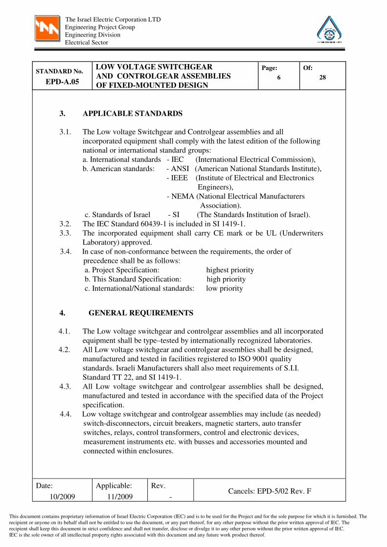
3. APPLICABLE STANDARDS
3.1. The Low voltage Switchgear and Controlgear assemblies and all
incorporated equipment shall comply with the latest edition of the following
national or international standard groups:
a. International standards - IEC (International Electrical Commission),
b. American standards: - ANSI (American National Standards Institute),
- IEEE (Institute of Electrical and Electronics
Engineers),
- NEMA (National Electrical Manufacturers
Association).
c. Standards of Israel - SI (The Standards Institution of Israel).
3.2. The IEC Standard 60439-1 is included in SI 1419-1.
3.3. The incorporated equipment shall carry CE mark or be UL (Underwriters
Laboratory) approved.
3.4. In case of non-conformance between the requirements, the order of
precedence shall be as follows:
a. Project Specification: highest priority
b. This Standard Specification: high priority
c. International/National standards: low priority
4. GENERAL REQUIREMENTS
4.1. The Low voltage switchgear and controlgear assemblies and all incorporated
equipment shall be type–tested by internationally recognized laboratories.
4.2. All Low voltage switchgear and controlgear assemblies shall be designed,
manufactured and tested in facilities registered to ISO 9001 quality
standards. Israeli Manufacturers shall also meet requirements of S.I.I.
Standard TT 22, and SI 1419-1.
4.3. All Low voltage switchgear and controlgear assemblies shall be designed,
manufactured and tested in accordance with the specified data of the Project
specification.
4.4. Low voltage switchgear and controlgear assemblies may include (as needed)
switch-disconnectors, circuit breakers, magnetic starters, auto transfer
switches, relays, control transformers, control and electronic devices,
measurement instruments etc. with busses and accessories mounted and
connected within enclosures.
Cancels: EPD-5/02 Rev. F Rev.
-
Applicable:
11/2009
Date:
10/2009

The Israel Electric Corporation LTD
Engineering Project Group
Engineering Division
Electrical Sector
This document contains proprietary information of Israel Electric Corporation (IEC) and is to be used for the Project and for the sole purpose for which it is furnished. The
recipient or anyone on its behalf shall not be entitled to use the document, or any part thereof, for any other purpose without the prior written approval of IEC. The
recipient shall keep this document in strict confidence and shall not transfer, disclose or divulge it to any other person without the prior written approval of IEC.
IEC is the sole owner of all intellectual property rights associated with this document and any future work product thereof.
Of:
28
Page:
7
LOW VOLTAGE SWITCHGEAR
AND CONTROLGEAR ASSEMBLIES
OF FIXED-MOUNTED DESIGN
STANDARD No.
EPD-A.05
4.5. The equipment mounted in the Low voltage switchgear and controlgear
assembly shall be fitted and wired in accordance with corresponding
Manufacturer’s instructions and recommendations. Minimizing of the Low
voltage switchgear and controlgear assembly size shall be taken
into account. The equipment and circuits in the Low voltage switchgear and
controlgear assembly shall be so arranged as to facilitate their operation and
maintenance and at the same time to ensure the necessary degree of safety.
4.6. The equipment mounted within the assembly shall have a clearance or
100-mm minimum around the perimeter of the enclosure and 50 mm from
the door.
4.7. All electrical equipment, bus bars, terminal blocks and covers of
connections of switching devices, mounted inside the assembly, shall be
IP 20 or NEMA Type 1 (general use) protected at least.
4.8. Terminal blocks’ mounting shall be as specified in Standard Specification
EPD-A.03, latest issue.
4.9. Arrangement of control devices shall be as specified in Annexure 1.
5. SERVICE CONDITIONS
5.1. The Low voltage switchgear and controlgear assemblies of fixed-mounted
design can be installed indoors in rooms with controlled air or rooms with
non-controlled air, or outdoors.
The service conditions of each type of installation are as follows:
5.2. Ambient air temperature:
The ambient temperature of the surrounding the equipment:
a. 10ºC to +40ºC
b. Average over a period of 24 h: +35ºC (+37ºC for installations in rooms with
non-controlled air).
5.3. Atmospheric conditions:
The relative humidity does not exceed 95% at a maximum temperature of +40ºC.
5.4 For outdoor installation the protection from direct solar radiation by using of
a sloping roof required.
5.5. Pollution degree:
The Low voltage switchgear and controlgear assemblies of fixed-mounted
design shall be designed for use in a pollution degree 3 environment.
Cancels: EPD-5/02 Rev. F Rev.
�
Applicable:
11/2009
Date:
10/2009

The Israel Electric Corporation LTD
Engineering Project Group
Engineering Division
Electrical Sector
This document contains proprietary information of Israel Electric Corporation (IEC) and is to be used for the Project and for the sole purpose for which it is furnished. The
recipient or anyone on its behalf shall not be entitled to use the document, or any part thereof, for any other purpose without the prior written approval of IEC. The
recipient shall keep this document in strict confidence and shall not transfer, disclose or divulge it to any other person without the prior written approval of IEC.
IEC is the sole owner of all intellectual property rights associated with this document and any future work product thereof.
Of:
28
Page:
8
LOW VOLTAGE SWITCHGEAR
AND CONTROLGEAR ASSEMBLIES
OF FIXED-MOUNTED DESIGN
STANDARD No.
EPD-A.05
5.6. Electromagnetic compatibility (EMC):
The Low voltage switchgear and controlgear assemblies of fixed-mounted
design shall be designed in accordance with Environment A conditions.
5.7. Seismicity:
The seismicity conditions shall be specified in the Project Specification.
5.8. Altitude:
Altitude of the site of the installation does not exceed 1000m above sea level.
5.9. Special service conditions:
During transport, storage and erection, for periods not exceeding 48 h, the
relative humidity may be as high as 70% at maximum temperature of +35ºC.
6. STRUCTURES AND HOUSINGS
6.1. The empty enclosures, prior to the incorporation of switchgear and controlgear
components by assemblies' manufacturer, shall comply with IEC Standard 62208.
6.2. The Low voltage switchgear and controlgear assemblies of fixed-mounted
design shall be constructed only of materials capable of withstanding the
mechanical, electrical and thermal stresses as well as the effects of humidity,
which are likely to be encountered in transportation, installation and normal
service condition for which the equipment is specified.
6.3. The assembly enclosures shall be made of high impact strength, self-
extinguishing fiberglass reinforced polyester, or shall have self-supporting
steel structure of reinforced steel sheet.
The steel sheets thickness shall be of 2.0 mm for doors and 1.5 mm for
bodies. If there is no equipment installed on the doors, the door steel sheet
may be of 1.5 mm thickness.
6.4. If the Low voltage switchgear and controlgear assembly contains more than
one (1) section, a barrier plate shall separate between both neighbor sections.
6.5. The housing of each Low voltage switchgear and controlgear assembly shall
have a hinged door or doors with concealed hinges, which will allow at least
180° door opening for wall-mounted assemblies and 120° for floor-mounted
assemblies. The doors shall be lockable.
6.6. The minimal degree of protection of a Low voltage switchgear and
controlgear assembly's enclosure shall be in accordance with its installation:
Cancels: EPD-5/02 Rev. F Rev.
�
Applicable:
11/2009
Date:
10/2009

The Israel Electric Corporation LTD
Engineering Project Group
Engineering Division
Electrical Sector
This document contains proprietary information of Israel Electric Corporation (IEC) and is to be used for the Project and for the sole purpose for which it is furnished. The
recipient or anyone on its behalf shall not be entitled to use the document, or any part thereof, for any other purpose without the prior written approval of IEC. The
recipient shall keep this document in strict confidence and shall not transfer, disclose or divulge it to any other person without the prior written approval of IEC.
IEC is the sole owner of all intellectual property rights associated with this document and any future work product thereof.
Of:
28
Page:
9
LOW VOLTAGE SWITCHGEAR
AND CONTROLGEAR ASSEMBLIES
OF FIXED-MOUNTED DESIGN
STANDARD No.
EPD-A.05
6.6.1. Indoor Installations:
a. Control and similar rooms with controlled air: IP 32 or NEMA Type 2
(drip tight).
b. Electrical and similar rooms with controlled air: IP 42 or
NEMA Type 12 (dust and drip tight).
c. Mechanical equipment, Turbine, Workshop, Office and other rooms
with controlled air and any rooms with non-controlled air: IP 54 or
NEMA Type 12 (dust and drip tight).
6.6.2. Outdoor installation: outdoor IP 65 and specially corrosion protected, or
NEMA Type 4X (rain and water tight, corrosion-resistant). The degree of
protection of assemblies equipped with cooling fans may be reduced to
IP 55.
6.7. Openings for cable entrances shall be equipped with adequately mounted
fittings.
6.8. For passage of wire and cables through openings provided in metal barriers,
insulation grommets or insulating ducts shall be used.
6.9. Enclosures of the Low voltage switchgear and controlgear assemblies
containing power circuits, rated more than 63 amperes, or containing
electronic equipment shall be equipped with removable plates
(250 x 250 mm approximately) on the top for mounting smoke detection and
fire fighting system devices.
Removable plate recommended location is the center of the enclosure roof
of each assembly section. 100 mm of a free space shall be kept at the upper
part of the enclosure.
6.10. Ventilation openings shall be covered with grilles and removable filters
according to protection degree of the assembly. Ventilation openings shall be
preferably on the front or side of the assembly.
6.11. Integral mounting bases shall be furnished as part of floor-mounted
assembly. These bases shall be suitable for welding to inserts in the concrete
floor or connection to the channel base, as applicable. Instruction for Low
voltage switchgear and controlgear assembly mounting (installation) shall be
provided by the Manufacturer.
6.12. Removable lifting eyes or angles shall be provided for lifting or moving the
equipment to its final location.
6.13. The Separation Forms required of the assemblies shall be defined in the
detailed Project Specification.
Cancels: EPD-5/02 Rev. F Rev.
�
Applicable:
11/2009
Date:
10/2009

The Israel Electric Corporation LTD
Engineering Project Group
Engineering Division
Electrical Sector
This document contains proprietary information of Israel Electric Corporation (IEC) and is to be used for the Project and for the sole purpose for which it is furnished. The
recipient or anyone on its behalf shall not be entitled to use the document, or any part thereof, for any other purpose without the prior written approval of IEC. The
recipient shall keep this document in strict confidence and shall not transfer, disclose or divulge it to any other person without the prior written approval of IEC.
IEC is the sole owner of all intellectual property rights associated with this document and any future work product thereof.
Of:
28
Page:
10
LOW VOLTAGE SWITCHGEAR
AND CONTROLGEAR ASSEMBLIES
OF FIXED-MOUNTED DESIGN
STANDARD No.
EPD-A.05
7. SWITCH-DISCONNECTORS
7.1. Switch-Disconnectors shall comply with IEC Standard 60947-3.
7.2. Electrical characteristic of Switch-Disconnectors shall be as follows:
7.2.1. Utilization category: AC-22A at least.
7.2.2. Rated operational voltage Ue: 400 VAC.
7.2.3. Rated insulated voltage Ui: 690 VAC.
7.2.4. Rated impulse withstand voltage Uimp: 6 kV.
7.2.5. Rated operational current Ie: not less, than upstream circuit breaker's rated
current.
7.2.6. Number of poles: as defined in the Project Specification.
7.3. Switch-Disconnectors shall be manually operated. They shall be capable of
making, carrying and breaking currents under normal circuit conditions,
which may include operating overload conditions and also carrying for 1 s
current under abnormal circuit conditions such as those of short-circuits. The
value of the rated of short-time withstand current shall be not less than
twelve times the maximum rated operational current.
7.4. Switch-Disconnectors shall be equipped with two "make" auxiliary contact
units at least. Rated operational current of a.m. contacts shall conform to
the requirements of I.E.C. Standard Specification EPD-A.20.
7.5. Changeover Switch-Disconnector shall have three mechanically
interlocked handle positions (I-OFF-II). Two auxiliary "make" contact
units shall be provided for each position.
8. COMBINATION STARTERS
8.1. Each combination starter shall consist of a circuit breaker, described
hereinafter under “CIRCUIT BREAKERS”, and a magnetic starter,
described hereinafter under “MAGNETIC STARTERS”.
8.2. The combination starters shall be Type 2 coordination as defined in the IEC
Standard 60947-4-1.
8.3. Magnetic starters for reversing and multi-speed motors shall be electrically
and mechanically interlocked.
Cancels: EPD-5/02 Rev. F Rev.
�
Applicable:
11/2009
Date:
10/2009
The Israel Electric Corporation LTD
Engineering Project Group
Engineering Division
Electrical Sector
This document contains proprietary information of Israel Electric Corporation (IEC) and is to be used for the Project and for the sole purpose for which it is furnished. The
recipient or anyone on its behalf shall not be entitled to use the document, or any part thereof, for any other purpose without the prior written approval of IEC. The
recipient shall keep this document in strict confidence and shall not transfer, disclose or divulge it to any other person without the prior written approval of IEC.
IEC is the sole owner of all intellectual property rights associated with this document and any future work product thereof.
Of:
28
Page:
11
LOW VOLTAGE SWITCHGEAR
AND CONTROLGEAR ASSEMBLIES
OF FIXED-MOUNTED DESIGN
STANDARD No.
EPD-A.05
9. CIRCUIT BREAKERS
9.1. Circuit Breakers shall comply with IEC Standard 60947-2.
9.2. Electrical characteristic of Circuit Breakers shall be as follows:
9.2.1. Utilization category: A.
9.2.2. Rated operational voltage Ue: 690 VAC (AC circuits) or 250 VDC (DC
circuits).
9.2.3. Rated insulated voltage Ui: 690 V (AC circuits) or 250 VDC (DC circuits).
9.2.4. Rated impulse withstand voltage Uimp: 6 kV.
9.2.5. Rated ultimate short-circuit breaking capacity and rated service short-
circuit breaking capacity will be greater, than the prospective short-circuit
current at the circuit breaker installation point.
9.2.6. Number of poles: as defined in the Project Specification.
9.2.7. Connection arrangement for DC circuits: 3 poles in series, unless otherwise
specified in the Project Specification.
9.3. Circuit Breakers shall be preferably molded case type, manually operated,
trip free circuit breakers. Circuit Breakers shall be equipped with auxiliary
and trip indicating contacts units. Rated operational current of a.m.
contacts shall conform to the requirements of I.E.C. Standard Specification
EPD-A.20. The use of other accessories, such as a rotary handle, a remote
operator, shunt opening and undervoltage releases and etc. shall be defined
in the Project Specification.
9.4. Circuit Breakers for feeder (other than motor) load protection will include
the thermal-magnetic trip unit with adjustable thermal overload releases
and adjustable or fixed magnetic short-circuit releases. The magnetic short-
circuit releases shall be adjustable to not more, than ten times the load rated
current.
9.5. Circuit Breakers for motor protection will include the adjustable magnetic
release trip unit or thermal-magnetic trip unit with adjustable thermal
overload and magnetic short-circuit releases. In last case, the thermal
overload releases may be omitted. The magnetic short-circuit releases shall
be adjustable to thirteen - fifteen times the motor rated current.
9.6. All circuit breakers shall be rated for the specified current carrying capacity
and the interrupting duty.
Cancels: EPD-5/02 Rev. F Rev.
-
Applicable:
11/2009
Date:
10/2009

The Israel Electric Corporation LTD
Engineering Project Group
Engineering Division
Electrical Sector
This document contains proprietary information of Israel Electric Corporation (IEC) and is to be used for the Project and for the sole purpose for which it is furnished. The
recipient or anyone on its behalf shall not be entitled to use the document, or any part thereof, for any other purpose without the prior written approval of IEC. The
recipient shall keep this document in strict confidence and shall not transfer, disclose or divulge it to any other person without the prior written approval of IEC.
IEC is the sole owner of all intellectual property rights associated with this document and any future work product thereof.
Of:
28
Page:
12
LOW VOLTAGE SWITCHGEAR
AND CONTROLGEAR ASSEMBLIES
OF FIXED-MOUNTED DESIGN
STANDARD No.
EPD-A.05
10. MAGNETIC STARTERS
10.1. Magnetic starters shall comply with IEC Standard 60947-4-1.
10.2. Magnetic starters shall consist of contactors and overload relays. If the
circuit breaker with thermal-magnetic releases applies, the overload relays
may be omitted.
10.3. Contactors shall be chosen for 106 operations.
10.4. Each contactor shall be fitted with accessories, such as auxiliary contact
blocks, etc.
10.5. Electrical characteristic of contactors shall be as follows:
10.5.1. Main contacts:
10.5.1.1. Utilization category: AC-3 or DC-3.
10.5.1.2. Rated operational voltage Ue: 690 VAC (AC circuits) or
250 VDC (DC circuits).
10.5.1.3. Rated insulated voltage Ui: 690 V (AC circuits) or 250 VDC (DC circuits).
10.5.1.4. Rated impulse withstand voltage Uimp: 6 kV.
10.5.1.5. Number of poles: 3 (AC circuits). For DC circuits it shall be defined in
the Project Specification.
10.5.2. Connection arrangement for DC circuits: as defined in the Project
Specification.
10.5.3 Starting duty (class): 10.
10.5.4 Auxiliary contacts rated current shall conform to the requirements of
I.E.C. Standard Specification EPD-A.20.
10.5.5 Coil voltage Uc: 230 VAC, 50 Hz (AC circuits) or 220 VDC (DC circuits).
Operating range (0.8 – 1.1) x Uc.
10.6. Thermal overload relays shall be three-element trip class 10 with one
make and one break auxiliary contacts, a selector for manual and
automatic reset, a test pushbutton and trip indication.
10.7. For overload protection of motors with severe long time starting duty
electronic motor-protective relays with adjustable trip class setting or
Thermistor overload relays shall be applied. The rated operational current
of the contactor, designed for Trip class 10, has to be reduced depending
on Trip class setting of overload relay.
Cancels: EPD-5/02 Rev. F Rev.
-
Applicable:
11/2009
Date:
10/2009

The Israel Electric Corporation LTD
Engineering Project Group
Engineering Division
Electrical Sector
This document contains proprietary information of Israel Electric Corporation (IEC) and is to be used for the Project and for the sole purpose for which it is furnished. The
recipient or anyone on its behalf shall not be entitled to use the document, or any part thereof, for any other purpose without the prior written approval of IEC. The
recipient shall keep this document in strict confidence and shall not transfer, disclose or divulge it to any other person without the prior written approval of IEC.
IEC is the sole owner of all intellectual property rights associated with this document and any future work product thereof.
Of:
28
Page:
13
LOW VOLTAGE SWITCHGEAR
AND CONTROLGEAR ASSEMBLIES
OF FIXED-MOUNTED DESIGN
STANDARD No.
EPD-A.05
11. CONTROL TRANSFORMERS
11.1. Control transformers shall comply with IEC Standard 61558-2-2.
11.2. Control transformer shall be single phase. Rated input voltage 400 VAC,
rated output voltage 230 VAC, frequency 50 Hz.
11.3. Rated short-circuit voltage of the transformer shall be within a range
2.5 – 4%.
11.4. The primary winding (400 VAC) shall have two taps for ±5% of rated
voltage.
11.5. The transformers shall have copper winding with thermal class B
insulation, vacuum varnish impregnated and shall be epoxy coated.
11.6. The transformers shall be of low noise type.
11.7. The transformers shall be equipped with terminals.
11.8. The transformers shall be electrically protected on both sides by circuit
breakers and one secondary terminal grounded.
11.9. The 230/24 V transformers shall be as defined above, except para. 11.4
and 11.8. The transformers shall be electrically protected on both sides by
circuit breakers and secondary terminals will not be grounded.
11.10. The primary side circuit breaker shall have protection unit specially
intended for transformer protection (magnetic short-circuit releases shall
be of twenty five times the transformer primary rated current). If the
circuit breaker is provided with another protection unit type, it shall be
chosen according to the high value of the transformer inrush current
(approximately 25 times the primary rated current).
11.11. The rated power of control transformer shall be calculated by adding the
sealing consumption of all simultaneously connected loads and the inrush
consumption of the largest load, and multiplying the result by 0.8. Where
the loads are of roughly the same size, sum of the inrush consumption of
all simultaneously connected loads shall be added to the sum of the
sealing consumption, and the result shall be multiplied by 0.8.
Cancels: EPD-5/02 Rev. F Rev.
-
Applicable:
11/2009
Date:
10/2009

The Israel Electric Corporation LTD
Engineering Project Group
Engineering Division
Electrical Sector
This document contains proprietary information of Israel Electric Corporation (IEC) and is to be used for the Project and for the sole purpose for which it is furnished. The
recipient or anyone on its behalf shall not be entitled to use the document, or any part thereof, for any other purpose without the prior written approval of IEC. The
recipient shall keep this document in strict confidence and shall not transfer, disclose or divulge it to any other person without the prior written approval of IEC.
IEC is the sole owner of all intellectual property rights associated with this document and any future work product thereof.
Of:
28
Page:
14
LOW VOLTAGE SWITCHGEAR
AND CONTROLGEAR ASSEMBLIES
OF FIXED-MOUNTED DESIGN
STANDARD No.
EPD-A.05
12. MINIATURE CIRCUIT BREAKERS
12.1. Miniature circuit breakers (MCB) shall comply with IEC Standards
60947-2.
12.2. Miniature circuit breakers connected to the power circuits shall satisfy
the same requirements as defined heretofore for the circuit breakers. The
rated operational voltage Ue shall be not less, than rated operational
voltage Ue of circuits which MCB connected to. The values of rated
insulation voltage Uimp shall be as specified in para. 9.2.3.
12.3. Electrical characteristics and accessories of miniature circuit breakers,
connected to the control circuits shall be specified in the Project
Specifications.
12.4. Application of fuses is not recommended. Use of miniature circuit
breakers is preferred.
13. CONTROL DEVICES
13.1. Control devices (push buttons, control switches, auxiliary and timing
relays etc.) shall comply with IEC Standard 60947-5-1.
13.2. The contacts' rating shall be as defined in the I.E.C. Standard Specification
EPD-A.20, latest issue. The contacts shall have 500 volts rated insulation
voltage at least.
13.3. Auxiliary and timing relays’ coil voltage Uc shall be according to control
circuits rated voltage with operating range (0.8 – 1.1) x Uc.
13.4. All control devices shall be enclosed, protected and accessible for
maintenance.
13.5. Door mounted control and measurement devices and other instruments
shall be IP54 or NEMA 12 type for indoor installations and IP65 corrosion
resistant type or NEMA 4X type for outdoor installations.
13.6. Door mounted push buttons for outdoor installations shall be equipped
with transparent protective boots.
13.7. For uniformity and minimization of operating errors, the color,
arrangement, direction of operation and nomenclature of push buttons,
control switches and indicating lights shall be consistent throughout.
Although many devices have their own standardized conventions, their
arrangement and colors shall be in accordance with definitions
described in Annexure 1.
Cancels: EPD-5/02 Rev. F Rev.
�
Applicable:
11/2009
Date:
10/2009

The Israel Electric Corporation LTD
Engineering Project Group
Engineering Division
Electrical Sector
This document contains proprietary information of Israel Electric Corporation (IEC) and is to be used for the Project and for the sole purpose for which it is furnished. The
recipient or anyone on its behalf shall not be entitled to use the document, or any part thereof, for any other purpose without the prior written approval of IEC. The
recipient shall keep this document in strict confidence and shall not transfer, disclose or divulge it to any other person without the prior written approval of IEC.
IEC is the sole owner of all intellectual property rights associated with this document and any future work product thereof.
Of:
28
Page:
15
LOW VOLTAGE SWITCHGEAR
AND CONTROLGEAR ASSEMBLIES
OF FIXED-MOUNTED DESIGN
STANDARD No.
EPD-A.05
13.8. Two indicating lights with complementary actions, such as a red and
green are adjacent in most cases to avoid confusion when a lamp burns
out.
13.9. The indicating lights for valves, dampers and other devices that require a
considerable travel time shall be connected so that both lights are on
during the device travel time to clearly indicate this condition.
14. SPACE HEATERS
14.1. In indoor and outdoor enclosures with internal space, exceeding 0.25 m3,
space heaters shall be installed against the effects of moisture and low
temperatures. They shall be suitable for continuous operation and
controlled by separate thermostats. Guide values for heater sizing: 200
watt/ m3 for outdoor and 100 watt/ m
3 for indoor.
14.2. Space heaters will be rated 240 VAC, but connected to 230 VAC power
supply busses. Space heaters shall be fitted at the bottom of the enclosure
and thermostats at the top.
14.3. A hygrostat (relative humidity control) may be applicable instead of a
thermostat.
14.4. If the space heater and cooling fan are fitted in the same assembly section,
they have to be controlled by a common thermostat.
15. COOLING FANS
15.1. In order to avoid malfunctions and faults at equipment operation, as a
result of overheating, cooling fans shall be installed in the enclosures of
Low voltage switchgear and controlgear assemblies containing electronic
devices like programmable controllers, microprocessor-based controllers
etc., if required by results of computations of temperature-rise limits (see
para.22.4.2). They shall be suitable for continuous operation and
controlled by separate thermostats. The thermostats shall be set at 30°C
rise at most.
15.2. Cooling fans will be rated 240 VAC, 50 Hz and connected to 230 VAC
power supply busses.
Cancels: EPD-5/02 Rev. F Rev.
�
Applicable:
11/2009
Date:
10/2009

The Israel Electric Corporation LTD
Engineering Project Group
Engineering Division
Electrical Sector
This document contains proprietary information of Israel Electric Corporation (IEC) and is to be used for the Project and for the sole purpose for which it is furnished. The
recipient or anyone on its behalf shall not be entitled to use the document, or any part thereof, for any other purpose without the prior written approval of IEC. The
recipient shall keep this document in strict confidence and shall not transfer, disclose or divulge it to any other person without the prior written approval of IEC.
IEC is the sole owner of all intellectual property rights associated with this document and any future work product thereof.
Of:
28
Page:
16
LOW VOLTAGE SWITCHGEAR
AND CONTROLGEAR ASSEMBLIES
OF FIXED-MOUNTED DESIGN
STANDARD No.
EPD-A.05
15.3. It is recommended that the fan be installed in the lower part of the
enclosure and fresh air drawn from outside to increase the life of the fan
motor and prevent dust penetration. The outlet opening shall be
preferably located near the top of the enclosure.
15.4. The fan and outlet units shall be IP 54 protected at least and equipped
with replaceable filters.
16. OTHER DEVICES
16.1. Other devices not specified herein, such as measuring instruments,
programmable controllers, electronic regulators, power supply units,
variable speed drives, auto transfer switches, etc., can be mounted in Low
voltage switchgear and controlgear assemblies.
16.2. These devices shall comply with any International or National Standard
and shall be of manufacturer’s standard line product.
16.3. The requirements for a.m. devices shall be specified in the Project
Specifications.
17. BUS BARS
17.1. Design and installation of Low voltage switchgear and controlgear
assemblies’ busses shall comply with IEC Standard 60439-1.
17.2. Power and control busses shall be solid hard drawn coppers.
17.3. Main busses shall be isolated by means of a special cover made from
dielectric materials.
17.4. The neutral bus (N) shall run along the entire length of each Low voltage
switchgear and controlgear assemblies.
17.5. The busses shall be painted (marked) as per I.E.C. Standard Specification
EPD-A.03, latest issue.
Cancels: EPD-5/02 Rev. F Rev.
�
Applicable:
11/2009
Date:
10/2009
The Israel Electric Corporation LTD
Engineering Project Group
Engineering Division
Electrical Sector
This document contains proprietary information of Israel Electric Corporation (IEC) and is to be used for the Project and for the sole purpose for which it is furnished. The
recipient or anyone on its behalf shall not be entitled to use the document, or any part thereof, for any other purpose without the prior written approval of IEC. The
recipient shall keep this document in strict confidence and shall not transfer, disclose or divulge it to any other person without the prior written approval of IEC.
IEC is the sole owner of all intellectual property rights associated with this document and any future work product thereof.
Of:
28
Page:
17
LOW VOLTAGE SWITCHGEAR
AND CONTROLGEAR ASSEMBLIES
OF FIXED-MOUNTED DESIGN
STANDARD No.
EPD-A.05
18. GROUNDING
18.1. The Low voltage switchgear and controlgear assemblies grounding shall
comply with IEC Standard 60439-1.
18.2. All assemblies shall be equipped with a copper protective earth (PE) bus,
extending over the entire length of each assembly.
18.3. The mechanical structure, all metallic non-live parts (doors included) and
all devices having a grounding terminal shall be connected directly to the
protective earth bus.
18.4. In the Controlgear assemblies containing control circuits devices only,
special grounding terminals may be used. In this case a mounting rail is
also used as a protective earth (PE) bus.
19. TERMINAL BLOCKS AND WIRING
19.1. Terminal blocks and wiring shall comply with Standard Specification
EPD-A.03, latest issue.
19.2. Power circuit connections to the starters shall be with conductors,
insulated for 750 volt rating, and shall be of ample current carrying
capacity for the largest load the starter can carry.
20. NAMEPLATES
20.1. Nameplates shall comply with I.E.C. Standard Specification
EPD-A.21, latest issue.
20.2. All inside and door mounted assembly equipment shall be properly
tagged and prominently identified with a nameplate designation as
approved by Purchaser. Each Low voltage switchgear and controlgear
assemblies shall be provided with a nameplate on door indicating
purchaser's Tag Number and its designation (in Hebrew).
21. PAINTING
Painting for sheet-metal housing shall comply with I.E.C. Standard
Specification EPD-2A, latest issue or I.E.C. Standard Specification
EPD-2, latest issue, for Israeli manufacturers.
Cancels: EPD-5/02 Rev. F Rev.
�
Applicable:
11/2009
Date:
10/2009

The Israel Electric Corporation LTD
Engineering Project Group
Engineering Division
Electrical Sector
This document contains proprietary information of Israel Electric Corporation (IEC) and is to be used for the Project and for the sole purpose for which it is furnished. The
recipient or anyone on its behalf shall not be entitled to use the document, or any part thereof, for any other purpose without the prior written approval of IEC. The
recipient shall keep this document in strict confidence and shall not transfer, disclose or divulge it to any other person without the prior written approval of IEC.
IEC is the sole owner of all intellectual property rights associated with this document and any future work product thereof.
Of:
28
Page:
18
LOW VOLTAGE SWITCHGEAR
AND CONTROLGEAR ASSEMBLIES
OF FIXED-MOUNTED DESIGN
STANDARD No.
EPD-A.05
22. INSPECTION AND TESTS
22.1 The Contractor shall submit with his proposal a preliminary Test and
Inspection plan.
22.2 The incorporated equipment shall be tested in accordance with the latest
SI or IEC Standards. The tests shall be conducted by an authorized body.
22.3 Each Low voltage switchgear and controlgear assembly shall be
tested in accordance with SI 1419-1 and IEC Standard 60439-1.
The tests shall be performed as specified in IEC Standard 60439-1 clause 8.
22.4 Type-tested Low voltage switchgear and controlgear assembly (TTA).
22.4.1 Each Low voltage switchgear and controlgear assembly stated as TTA
shall be subjected to the type test. The type test shall be performed as
specified in IEC Standard 60439-1 sub-clauses 8.1.1, 8.1.3 and 8.2.
The type test shall be conducted by an authorized body.
22.4.2 Type test certificates and reports shall be submitted to the Purchaser with
the Proposal.
The certificates and reports shall be issued by authorized body,
performed tests.
If the Contractor is not an original equipment manufacturer (OEM), the
License given by OEM shall be submitted together with the type test
certificates of assemblies fabricated by OEM. The type test reports
shall cover the applied procedure, standards and shall contain
actual values measured.
22.5 Partially type-tested Low voltage switchgear and controlgear assembly
(PTTA).
22.5.1 For each Low voltage switchgear and controlgear assembly stated as
PTTA all verifications shall either be made by tests, or by computations,
as required by SI 1419-1 and IEC Standard 60439-1, and specified in IEC
Standard 60439-1 the table 7 "List of verifications and tests to be
performed on TTA and PTTA".
22.5.2 Computations of temperature-rise limits shall be performed in accordance
with IEC Standard 60890. An ambient temperature shall be defined as
40°C. A rated diversity factor of an assembly shall be as specified in IEC
Standard 60439-1 sub-clause 4.7.
22.5.3 Computations of short-circuit withstand strength shall be performed in
accordance with IEC Standard 60865. A verification of the short-circuit
withstand strength is not required in the cases covered by IEC Standard
60439-1 sub-clause 8.2.3.1.
Cancels: EPD-5/02 Rev. F Rev.
�
Applicable:
11/2009
Date:
10/2009

The Israel Electric Corporation LTD
Engineering Project Group
Engineering Division
Electrical Sector
This document contains proprietary information of Israel Electric Corporation (IEC) and is to be used for the Project and for the sole purpose for which it is furnished. The
recipient or anyone on its behalf shall not be entitled to use the document, or any part thereof, for any other purpose without the prior written approval of IEC. The
recipient shall keep this document in strict confidence and shall not transfer, disclose or divulge it to any other person without the prior written approval of IEC.
IEC is the sole owner of all intellectual property rights associated with this document and any future work product thereof.
Of:
28
Page:
19
LOW VOLTAGE SWITCHGEAR
AND CONTROLGEAR ASSEMBLIES
OF FIXED-MOUNTED DESIGN
STANDARD No.
EPD-A.05
22.5.4 All above computations to be made by computer program developed by
internationally recognized electrical equipment manufacturer.
22.5.5 The Contractor shall submit with his proposal a confirmation of
compliance of the proposed assemblies with SI 1419-1 and IEC Standard
60439-1. All verification reports shall be submitted together with the
assemblies Layout Diagrams. The reports shall be signed by the
Contractor, and shall contain actual values calculated as well as border
values permitted.
22.6 Each Low voltage switchgear and controlgear assembly shall be subjected
to the routine test. The test shall be performing as specified in IEC
Standard 60439-1 sub-clauses 8.1.2, 8.1.3 and 8.3. The routine test shall
be carried out at the factory on every assembly after its assembly or on
each transport unit. Test certificates shall be submitted to Purchaser
immediately following their generation. The certificates shall be original,
signed by the Contractor, and shall contain actual values measured.
22.7 The Contractor, upon request, shall provide the Purchaser with advance
notice of final assembly and testing.
22.8 The completely assembled equipment shall be given a simulated
operational test at the factory in order to guarantee its operation.
22.9 Immediately following shipment the Contractor shall submit
certified test reports covering the guaranteed requirements,
manufacturer’s Standard and commercial tests and other tests as
specified.
22.10 Purchaser's representatives shall have the right to inspect the assemblies
any time during manufacture and shall have the right to participate on
tests made on the assemblies covered by this specification.
22.11 The Contractor shall give two (2) weeks notice as to the time
and place, when each part of work will be ready for inspection.
22.12 The Purchaser may reject any part of work found not to be in accordance
with this Specification or the Project Specification, regardless of the
stage of its completion or the time or place of discovery of errors.
22.13 The inspection of Purchaser shall in no way relieve the Contractor from
obligations to furnish the equipment in accordance with this
Specification or the Project Specification.
Cancels: EPD-5/02 Rev. F Rev.
�
Applicable:
11/2009
Date:
10/2009

The Israel Electric Corporation LTD
Engineering Project Group
Engineering Division
Electrical Sector
This document contains proprietary information of Israel Electric Corporation (IEC) and is to be used for the Project and for the sole purpose for which it is furnished. The
recipient or anyone on its behalf shall not be entitled to use the document, or any part thereof, for any other purpose without the prior written approval of IEC. The
recipient shall keep this document in strict confidence and shall not transfer, disclose or divulge it to any other person without the prior written approval of IEC.
IEC is the sole owner of all intellectual property rights associated with this document and any future work product thereof.
Of:
28
Page:
20
LOW VOLTAGE SWITCHGEAR
AND CONTROLGEAR ASSEMBLIES
OF FIXED-MOUNTED DESIGN
STANDARD No.
EPD-A.05
23. QUALITY ASSURANCE
23.1 In addition to the provisions of the General Conditions "CONTRACTOR'S
DOCUMENTATION" and "QUALITY ASSURANCE, INSPECTION, AND
TESTING" attached to the Project Specification, the Contractor's Quality
Assurance Program shall meet the requirements described in ISO
Standard 9001.
23.2 The Purchaser shall have the right to audit and comment on Contractor's Quality
Assurance System regardless of whether it was previously audited by a certifying
agency or any other body.
23.3 In the case of Purchaser's acceptance of such alternates or additions to Standards
and Codes, Contractor remains responsible for assuring that the design, and
physical interfaces between the supplied Equipment and the equipment
supplied by others which confirm to IEC standard, are completely compatible.
23.4 The Contractor will submit with his proposal a copy of his Quality Assurance
Manual including Quality Procedures.
23.5 List of Standards:
See Para.26.
23.6 The Contractor will submit with his proposal a copy of his Quality
Assurance Manual including Quality Procedures.
24. PACKAGE AND SHIPPING
24.1 The equipment shall be packed, crated and braced to protect it from
damage in handling during shipment and from inclement weather.
24.2 The contents, Contract or Bill of Material Item Number and I.E.C. Order
Number shall be clearly marked on the exterior of each packing unit.
24.3 The equipment shall be shipped in sections that will minimize erection
time at the I.E.C. construction sites, but can be safely handled by the
I.E.C. unloading facilities.
24.4 The Contractor shall provide all necessary storage instructions required to
maintain the original condition of the equipment before installation and
until the equipment is placed in service.
Cancels: EPD-5/02 Rev. F Rev.
�
Applicable:
11/2009
Date:
10/2009
The Israel Electric Corporation LTD
Engineering Project Group
Engineering Division
Electrical Sector
This document contains proprietary information of Israel Electric Corporation (IEC) and is to be used for the Project and for the sole purpose for which it is furnished. The
recipient or anyone on its behalf shall not be entitled to use the document, or any part thereof, for any other purpose without the prior written approval of IEC. The
recipient shall keep this document in strict confidence and shall not transfer, disclose or divulge it to any other person without the prior written approval of IEC.
IEC is the sole owner of all intellectual property rights associated with this document and any future work product thereof.
Of:
28
Page:
21
LOW VOLTAGE SWITCHGEAR
AND CONTROLGEAR ASSEMBLIES
OF FIXED-MOUNTED DESIGN
STANDARD No.
EPD-A.05
25. TECHNICAL DATA AND DOCUMENTATION
25.1 After award of the contract the Contractor shall submit the equipment
catalogs, prospects and documents as indicated bellow ( at least ,but not
limited to ), as well as documents as specified elsewhere in this Standard,
unless otherwise specified in the Project Specification.
The said documentation will be submitted for either approval or
information, as follows:
25.1.1 For Approval Documentation.
25.1.1.1 Drawings list.
25.1.1.2 Complete List of Electrical Equipment furnished by Contractor and
all data necessary to clearly define the electrical apparatus and instruments.
25.1.1.3 Key Diagrams of complete electrical circuits in accordance with
Purchaser requirements and/or drawings.
25.1.1.4 Power requirements and power connections for all devices, including a
complete internal power distribution drawing .
25.1.1.5 Schematic Diagrams, external connections, covering all electrical
equipment that is factory wired as an integral part of the specification
All equipment shall be labeled with a tag number in accordance with
Purchaser documentation.
25.1.1.6 Assembly’s Layout Drawings with electrical equipment, details of bus
bars, connections, terminals etc., marked according to the Contractor’s
Key and Schematic Diagram. The drawings shall include the assembly
size.
25.1.1.7 Complete Wiring Diagrams showing all wiring connections for all
equipment furnished by Contractor. Wiring Diagram shall leave no
question as to the location of two (2) end terminations of each and every
wire within the assembly. Connections to external wiring shall be shown
at terminal blocks and each device shall be properly identified.
25.1.1.8 Nameplates List.
25.1.1.9 Spare parts List.
25.1.1.10 Quality Assurance Documentation, as per Para 23.
25.1.1.11 Purchaser may require the right to approve any other drawings supplied by
Contractor.
Cancels: EPD-5/02 Rev. F Rev.
�
Applicable:
11/2009
Date:
10/2009
The Israel Electric Corporation LTD
Engineering Project Group
Engineering Division
Electrical Sector
This document contains proprietary information of Israel Electric Corporation (IEC) and is to be used for the Project and for the sole purpose for which it is furnished. The
recipient or anyone on its behalf shall not be entitled to use the document, or any part thereof, for any other purpose without the prior written approval of IEC. The
recipient shall keep this document in strict confidence and shall not transfer, disclose or divulge it to any other person without the prior written approval of IEC.
IEC is the sole owner of all intellectual property rights associated with this document and any future work product thereof.
Of:
28
Page:
22
LOW VOLTAGE SWITCHGEAR
AND CONTROLGEAR ASSEMBLIES
OF FIXED-MOUNTED DESIGN
STANDARD No.
EPD-A.05
25.1.2 For Information Documentation.
25.1.2.1 Test reports and certificates:
• Type test reports and certificates.
• Certified routine test reports.
• Certified test reports covering the guaranteed requirements,
manufacturer’s Standard and commercial tests and other tests as specified.
25.1.2.2 Computations, as specified in Para 22.
25.1.2.3 Instruction Books.
25.1.2.4 Low voltage switchgear and controlgear assemblies data sheets
according to the Annexure 3.
25.1.2.5 Catalogs, Prospects that have not been submitted with the Proposal.
24.1.2.6 " As shipped " Drawings.
25.2 With Proposal Documentation.
25.2.1 Key Diagrams of electrical circuits in accordance with Purchaser
requirements, as defined in the Project Specification.
25.2.2 Layout Drawings, including assembly's size and cable entrance details.
25.2.3 Summary of data (the format for Summary of data , as per Annexure 4
attached hereto).
25.2.4 Equipment Catalogs, Prospects.
25.2.5 Type test certificates and reports for TTA assemblies or confirmation for
compliance of the proposed assemblies with SI 1419-1 and IEC Standard
60439-1 for PTTA assemblies.
25.3 The specific requirements for data and documentation , including their
delivery time, will be included in the project Specification as :
" Annexure J " – Documentation Submission Schedule.
Cancels: EPD-5/02 Rev. F Rev.
�
Applicable:
11/2009
Date:
10/2009

The Israel Electric Corporation LTD
Engineering Project Group
Engineering Division
Electrical Sector
This document contains proprietary information of Israel Electric Corporation (IEC) and is to be used for the Project and for the sole purpose for which it is furnished. The
recipient or anyone on its behalf shall not be entitled to use the document, or any part thereof, for any other purpose without the prior written approval of IEC. The
recipient shall keep this document in strict confidence and shall not transfer, disclose or divulge it to any other person without the prior written approval of IEC.
IEC is the sole owner of all intellectual property rights associated with this document and any future work product thereof.
Of:
28
Page:
23
LOW VOLTAGE SWITCHGEAR
AND CONTROLGEAR ASSEMBLIES
OF FIXED-MOUNTED DESIGN
STANDARD No.
EPD-A.05
26. LIST OF STANDARDS
26.1 IEC Std. 60439-1. Low-voltage switchgear and controlgear assemblies-
Part 1: Type-tested and partially type-tested assemblies.
26.2 IEC Std. 60947-2. Low-voltage switchgear and controlgear - Part 2: Circuit
breakers.
26.3 IEC Std. 60947-3. Low-voltage switchgear and controlgear - Part 3:
Switches, disconnectors, switch-disconnectors and fuse combination units.
26.4 IEC Std. 60947-4-1. Low-voltage switchgear and controlgear - Part 4:
Contactors and motor-starters - Section one: Electrotechnical contactors and
motor-starters.
26.5 IEC Std. 60947-5-1. Low-voltage switchgear and controlgear - Part 5:
Control circuit devices and switching elements - Section one:
Electromechanical control circuit devices.
26.6 IEC Std. 61558-2-2. Safety of power transformers, power supply units and
similar – Part 2-2: Particular requirements for control transformers.
26.7 IEC Std. 60865. Short-circuit currents – computation of effects.
26.8 IEC Std. 60890. A method of temperature-rise assessment.
26.9 IEC Std. 62208. Empty enclosures for low-voltage switchgear and
controlgear assemblies – general requirements.
26.10 SI Std. 1419-1 : Low Voltage Switchgear and Controlgear assemblies:
Type-tested and partially Type-tested assemblies
26.11 S.I.I. Std. TT )ת"ת( 22. . דרישות ממערכת איכות של מפעלי� המייצרי� לוחות חשמל למתח נמו�
Cancels: EPD-5/02 Rev. F Rev.
�
Applicable:
11/2009
Date:
10/2009
The Israel Electric Corporation LTD
Engineering Project Group
Engineering Division
Electrical Sector
This document contains proprietary information of Israel Electric Corporation (IEC) and is to be used for the Project and for the sole purpose for which it is furnished. The
recipient or anyone on its behalf shall not be entitled to use the document, or any part thereof, for any other purpose without the prior written approval of IEC. The
recipient shall keep this document in strict confidence and shall not transfer, disclose or divulge it to any other person without the prior written approval of IEC.
IEC is the sole owner of all intellectual property rights associated with this document and any future work product thereof.
Of:
28
Page:
24
LOW VOLTAGE SWITCHGEAR
AND CONTROLGEAR ASSEMBLIES
OF FIXED-MOUNTED DESIGN
STANDARD No.
EPD-A.05
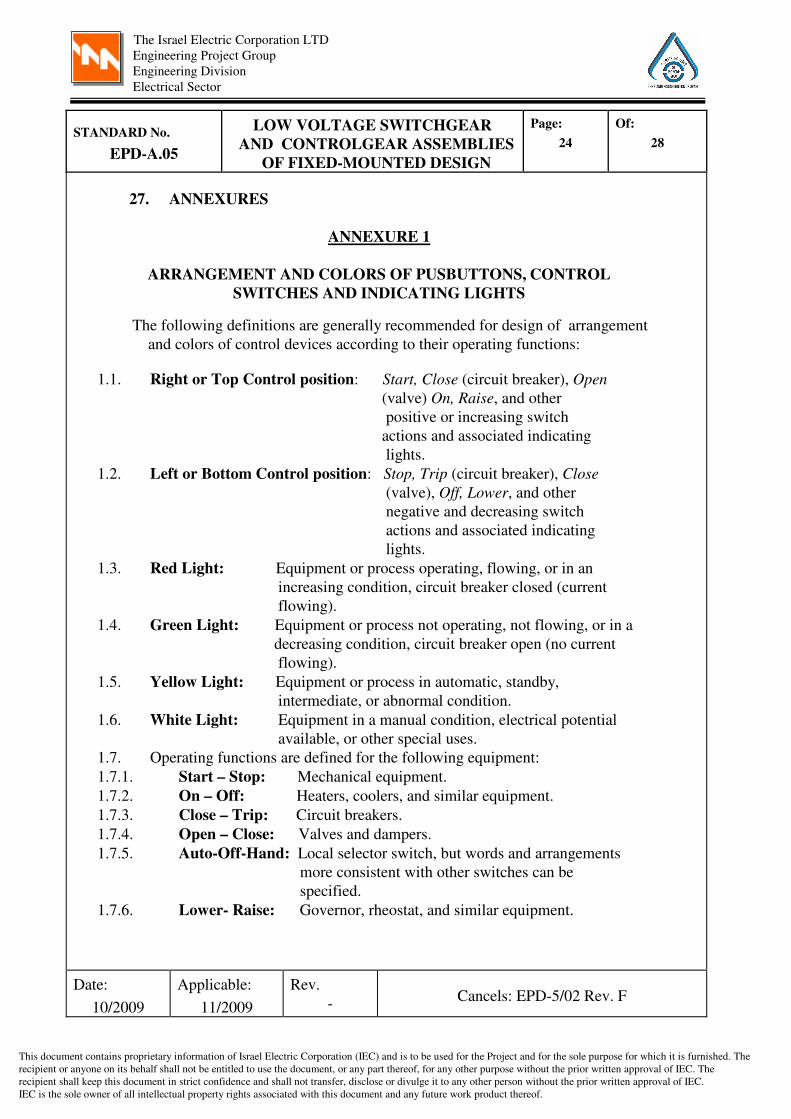
27. ANNEXURES
ANNEXURE 1
ARRANGEMENT AND COLORS OF PUSBUTTONS, CONTROL
SWITCHES AND INDICATING LIGHTS
The following definitions are generally recommended for design of arrangement
and colors of control devices according to their operating functions:
1.1. Right or Top Control position: Start, Close (circuit breaker), Open
(valve) On, Raise, and other
positive or increasing switch
actions and associated indicating
lights.
1.2. Left or Bottom Control position: Stop, Trip (circuit breaker), Close
(valve), Off, Lower, and other
negative and decreasing switch
actions and associated indicating
lights.
1.3. Red Light: Equipment or process operating, flowing, or in an
increasing condition, circuit breaker closed (current
flowing).
1.4. Green Light: Equipment or process not operating, not flowing, or in a
decreasing condition, circuit breaker open (no current
flowing).
1.5. Yellow Light: Equipment or process in automatic, standby,
intermediate, or abnormal condition.
1.6. White Light: Equipment in a manual condition, electrical potential
available, or other special uses.
1.7. Operating functions are defined for the following equipment:
1.7.1. Start – Stop: Mechanical equipment.
1.7.2. On – Off: Heaters, coolers, and similar equipment.
1.7.3. Close – Trip: Circuit breakers.
1.7.4. Open – Close: Valves and dampers.
1.7.5. Auto-Off-Hand: Local selector switch, but words and arrangements
more consistent with other switches can be
specified.
1.7.6. Lower- Raise: Governor, rheostat, and similar equipment.
Cancels: EPD-5/02 Rev. F Rev.
�
Applicable:
11/2009
Date:
10/2009

The Israel Electric Corporation LTD
Engineering Project Group
Engineering Division
Electrical Sector
This document contains proprietary information of Israel Electric Corporation (IEC) and is to be used for the Project and for the sole purpose for which it is furnished. The
recipient or anyone on its behalf shall not be entitled to use the document, or any part thereof, for any other purpose without the prior written approval of IEC. The
recipient shall keep this document in strict confidence and shall not transfer, disclose or divulge it to any other person without the prior written approval of IEC.
IEC is the sole owner of all intellectual property rights associated with this document and any future work product thereof.
Of:
28
Page:
25
LOW VOLTAGE SWITCHGEAR
AND CONTROLGEAR ASSEMBLIES
OF FIXED-MOUNTED DESIGN
STANDARD No.
EPD-A.05
ANNEXURE 2
DATA TO BE SPECIFIED
IN THE PROJECT SPECIFICATION
(By the Purchaser)
The following data ( at least , but not limited to ) shall be specified in the
Project Specification. (The numbers in parenthesis refer to the appropriate
paragraph of this Standard Specification):
1.1. Rated power and control operational voltages (Ue).
1.2. Rated insulation voltage (Ui).
1.3. Rated impulse withstand voltage (Uimp).
1.4. Rated frequency (fn).
1.5. Main busses rated current (In).
1.6. Rated short-time withstand current (1S) (Icw).
1.7. Rated peak withstand current (Ipk).
1.8. Rated diversity factor(s) (RDF) (if assemblies designed by Engineering
division of Israel Electric Corporation).
1.9. Size and quantity of power supply cables.
1.10. Interface to the Control and monitoring system.
1.11. Service conditions:
1.11.1 Ambient air temperature (5.2.1).
1.11.2 Atmospheric conditions (5.3).
1.11.3 Roof protection from direct solar radiation provided by Purchaser or
required by the Contractor for outdoor located assemblies, if any (5.4).
1.11.4 Degree of protection (6.6).
1.11.5 Pollution degree (5.5).
1.11.6 Electromagnetic compatibility (EMC) (5.6).
1.11.7 Seismicity of the site (5.7).
Cancels: EPD-5/02 Rev. F Rev.
�
Applicable:
11/2009
Date:
10/2009

The Israel Electric Corporation LTD
Engineering Project Group
Engineering Division
Electrical Sector
This document contains proprietary information of Israel Electric Corporation (IEC) and is to be used for the Project and for the sole purpose for which it is furnished. The
recipient or anyone on its behalf shall not be entitled to use the document, or any part thereof, for any other purpose without the prior written approval of IEC. The
recipient shall keep this document in strict confidence and shall not transfer, disclose or divulge it to any other person without the prior written approval of IEC.
IEC is the sole owner of all intellectual property rights associated with this document and any future work product thereof.
Of:
28
Page:
26
LOW VOLTAGE SWITCHGEAR
AND CONTROLGEAR ASSEMBLIES
OF FIXED-MOUNTED DESIGN
STANDARD No.
EPD-A.05.
ANNEXURE 3
LOW VOLTAGE SWITCHGEAR AND
CONTROLGEAR ASSEMBLIES DATA SHEET
Name of Supplier_______________ Date (MM/DD/YY)_____________
Purchaser's Tag Number :_________________
Insert data in this column
1. GENERAL
1.1 Specification number……..................
1.2 Manufacturer………………………...
1.3 Type/Catalog number
1.4 Type-test certificate number…………
1.5 Type-test report number……………..
1.6 Basic standards……………………....
2. SERVICE CONDITIONS
2.1 Ambient air temperature...(min ºC/max ºC)
2.2 Outdoor or indoor location…………..
2.3 Protection roof supplied….............(yes/no)
2.4 Pollution degree……………………...
2.5 Electromagnetic compatibility (EMC)…
2.6 Enclosure type (IP/NEMA)………….
3. MAIN ELECTRICAL DATA
3.1 Rated voltage…………………………(V)
3.2 Number of phases……………………
3.3 Rated insulation voltage ……….…….(V)
3.4 Rated impulse withstand voltage ….(KV)
3.5 Rated current…………………………(A)
3.6 Rated short-time withstand current
(1S)……………………………..(KArms)
3.7 Rated peak withstand current
(1S)……………………………..(KArms)
3.8 Current at maximum capability………(A)
3.9 Rated frequency……………………..(Hz)
3.10 Rated diversity factor(s) (RDF)……
3.11 Main switch-disconnector/circuit breaker:
3.11.1 Rated current…………………………(A)
3.11.2 Trip unit range (OL/SC)……………...(A)
Cancels: EPD-5/02 Rev. F Rev.
�
Applicable:
11/2009
Date:
10/2009
The Israel Electric Corporation LTD
Engineering Project Group
Engineering Division
Electrical Sector
This document contains proprietary information of Israel Electric Corporation (IEC) and is to be used for the Project and for the sole purpose for which it is furnished. The
recipient or anyone on its behalf shall not be entitled to use the document, or any part thereof, for any other purpose without the prior written approval of IEC. The
recipient shall keep this document in strict confidence and shall not transfer, disclose or divulge it to any other person without the prior written approval of IEC.
IEC is the sole owner of all intellectual property rights associated with this document and any future work product thereof.
Of:
28
Page:
27
LOW VOLTAGE SWITCHGEAR
AND CONTROLGEAR ASSEMBLIES
OF FIXED-MOUNTED DESIGN
STANDARD No.
EPD-A.05
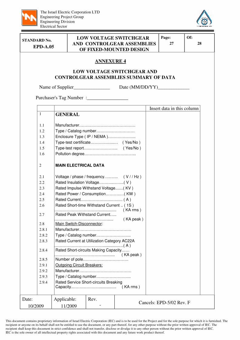
ANNEXURE 4
LOW VOLTAGE SWITCHGEAR AND
CONTROLGEAR ASSEMBLIES SUMMARY OF DATA
Name of Supplier_______________ Date (MM/DD/YY)_____________
Purchaser's Tag Number :_________________ Insert data in this column
1 GENERAL
1.1 Manufacturer…………………………………… 1.2 Type / Catalog number………..……………… 1.3 Enclosure Type ( IP / NEMA )………………... 1.4 Type-test certificate……………...… ( Yes/No ) 1.5 Type-test report…..………………... ( Yes/No ) 1.6 Pollution degree………………………………...
2 MAIN ELECTRICAL DATA
2.1 Voltage / phase / frequency…..…... ( V / / Hz ) 2.2 Rated Insulation Voltage………..……..( V ) 2.3 Rated Impulse Withstand Voltage.......( KV ) 2.4 Rated Power / Consumption………..…( KW ) 2.5 Rated Current…………………...….…. ( A ) 2.6 Rated Short-time Withstand Current .. ( 1S )
……………………………................ ( KA rms )
2.7 Rated Peak Withstand Current….. ……………………………….…..... ( KA peak )
2.8 Main Switch-Disconnector: 2.8.1 Manufacturer………………………………… 2.8.2 Type / Catalog number…………………….. 2.8.3 Rated Current at Utilization Category AC22A
………………………………...............…( A )
2.8.4 Rated Short-circuits Making Capacity…… ………………………………........... ( KA peak )
2.8.5 Number of pole……………………………. 2.9.1 Outgoing Circuit Breakers: 2.9.2 Manufacturer………………………………… 2.9.3 Type / Catalog number…………………….. 2.9.4 Rated Service Short-circuits Breaking
Capacity...………………................ ( KA rms )
Cancels: EPD-5/02 Rev. F Rev.
�
Applicable:
11/2009
Date:
10/2009

The Israel Electric Corporation LTD
Engineering Project Group
Engineering Division
Electrical Sector
This document contains proprietary information of Israel Electric Corporation (IEC) and is to be used for the Project and for the sole purpose for which it is furnished. The
recipient or anyone on its behalf shall not be entitled to use the document, or any part thereof, for any other purpose without the prior written approval of IEC. The
recipient shall keep this document in strict confidence and shall not transfer, disclose or divulge it to any other person without the prior written approval of IEC.
IEC is the sole owner of all intellectual property rights associated with this document and any future work product thereof.
Of:
28
Page:
28
LOW VOLTAGE SWITCHGEAR
AND CONTROLGEAR ASSEMBLIES
OF FIXED-MOUNTED DESIGN
STANDARD No.
EPD-A.05
Cont. :
Name of Supplier_______________
Date (MM/DD/YY)_____________
Purchaser's Tag Number :_________________
Insert data in this column 2.10. Miniature Circuit Breakers: 2.10.1 Manufacturer………………………….…… 2.10.2 Type / Catalog number…………………… 2.10.3 Rated Service Short-circuits Breaking
Capacity.. ………………........... ( KA rms )
2.11 Contactors: 2.11.1 Manufacturer………………………….…… 2.11.2 Type / Catalog number…………………… 2.11.3 Rated Operational Voltage............…( V ) 2.11.4 Coil Voltage with Operating Limits.… ( V ) 2.12 Control Transformers: 2.12.1 Manufacturer………………………….…… 2.12.2 Type / Catalog number…………………… 2.12.3 Power rating………………………..….(VA) 2.12.4 Primary/secondary voltage rating……(V) 2.12.5 Number of transformers………………….. 2.13 Control Devices: 2.13.1 Manufacturer………………………….…… 2.13.2 Degree of protection ( IP / NEMA )……… 2.14 Space heaters…..……………... ( Yes/No ) 2.14.1 Rated voltage………………………...(V) 2.15 Cooling fans...…..……………... ( Yes/No ) 2.15.1 Rated voltage………………………. .(V) 2.16 Thermostat...…..……….……... ( Yes/No ) 2.17 Terminal blocks type……………………… 2.18 Compliance with Purchaser's standards
attached (as per Annexure B Para …) ……..………………………….. ( Yes / No )
2.19 Compliance with site seismic environment requirements (as per Annexure B Para …) ……..………………………….. ( Yes / No )
-- FINAL --
Cancels: EPD-5/02 Rev. F Rev.
�
Applicable:
11/2009
Date:
10/2009